1
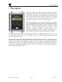
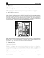
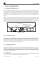
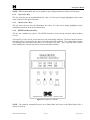
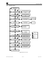
Model 240
Gas Detection/Alarm System
Operator’s Installation and Instruction Manual
DETCON, Inc.
3200 Research Forest Dr.,
The Woodlands, Texas 77387
Ph.281.367.4100 / Fax 281.298.2868
www.detcon.com
November 1, 2010 • Document #2923 • Revision 1.8
240 Operators Manual
This page left intentionally blank
Shipping Address: 3200 A-1 Research Forest Dr., The Woodlands Texas 77381
Mailing Address: P.O. Box 8067, The Woodlands Texas 77387-8067
Phone: 888.367.4286, 281.367.4100 • Fax: 281.292.2860 • www.detcon.com • [email protected]
Model 240 Operator Manual
Rev. 1.8
ii
240 Operators Manual
Table of Contents
1.
2.
3.
4.
Description.................................................................................................................................1
System Operation......................................................................................................................2
Specifications.............................................................................................................................3
Installation.................................................................................................................................4
4.1
4.2
Mounting and Cable Penetrations................................................................................................................... 4
Power and I/O Connections............................................................................................................................ 4
4.2.1
4.2.2
4.2.3
4.2.4
4.2.5
4.2.6
5.
Start-up......................................................................................................................................9
5.1
5.2
6.
Power Switch Selections ................................................................................................................................ 9
Applying Power.............................................................................................................................................. 9
System Configuration.............................................................................................................10
6.1
6.2
6.3
Analog/Serial input selection ....................................................................................................................... 10
Password Protection ..................................................................................................................................... 10
Navigating the Menus................................................................................................................................... 10
6.3.1
6.3.2
6.3.3
6.3.4
6.4
6.5
6.6
6.7
Menu Flow Chart...................................................................................................................13
Calibration Mode...................................................................................................................14
Set # of Channels ...................................................................................................................14
Set Channel Range.................................................................................................................14
Set Channel Type ...................................................................................................................14
Set Channel Alarms ...............................................................................................................15
Set Relay Functions ...............................................................................................................15
Set Date and Time..................................................................................................................15
Set Modbus Address: .............................................................................................................16
View TWA and Peak Readings...............................................................................................16
View Event Records ...............................................................................................................16
Download History..................................................................................................................16
Alarm Test Mode.......................................................................................................................................... 17
Display Contrast ........................................................................................................................................... 17
System Features ......................................................................................................................18
7.1
7.2
8.
PROG Key: ............................................................................................................................10
“Up Arrow” Key: ..................................................................................................................11
“Down Arrow” Key:..............................................................................................................11
ENTER and Reset/Ack Key: ...................................................................................................11
Main Display Functions ............................................................................................................................... 12
User-Interface Menu Functions .................................................................................................................... 12
6.5.1
6.5.2
6.5.3
6.5.4
6.5.5
6.5.6
6.5.7
6.5.8
6.5.9
6.5.10
6.5.11
6.5.12
7.
AC Power.................................................................................................................................4
DC Power ................................................................................................................................5
Analog 4-20 mA Sensor Inputs ................................................................................................5
Serial Input Gas Sensors..........................................................................................................7
Serial Polling of the Model 140 Controller .............................................................................8
Relay Outputs...........................................................................................................................8
Modbus Communications............................................................................................................................. 18
Download Procedure .................................................................................................................................... 20
Options.....................................................................................................................................26
8.1
8.2
8.3
8.4
8.5
Option for Battery Back-up Operation ......................................................................................................... 26
Option for 4-20mA Output(s)....................................................................................................................... 26
Optional Interface PCB for Remote Display ................................................................................................ 26
Optional Remote Alarm Reset/Acknowledge Switch .................................................................................. 27
Optional Type Z Enclosure Purge Assembly ............................................................................................... 27
Model 240 Operator Manual
Rev. 1.8
iii
240 Operators Manual
9. Troubleshooting Guide...........................................................................................................28
10.
Spare Parts...........................................................................................................................28
11.
Warranty..............................................................................................................................28
Appendix A .....................................................................................................................................29
Revision Log..............................................................................................................................................................29
Table of Figures
Figure 1 System Operational Diagram.............................................................................................................................2
Figure 2 Dimensional View of Enclosure ........................................................................................................................4
Figure 3 Power Input Schematic ......................................................................................................................................5
Figure 4 Mother Board Layout.........................................................................................................................................6
Figure 5 Control Board Layout ........................................................................................................................................7
Figure 6 Power Switch Configuration..............................................................................................................................9
Figure 7 Switch SW1 .....................................................................................................................................................10
Figure 8 Front Panel User Interface ...............................................................................................................................11
Figure 9 Menu Flow Chart .............................................................................................................................................13
Figure 10 Serial connection and jumper locations .........................................................................................................21
Figure 11 Invoking Hyper Terminal ..............................................................................................................................21
Figure 12 Connection Description .................................................................................................................................22
Figure 13 Connect to Configuration...............................................................................................................................22
Figure 14 Communications port properties....................................................................................................................23
Figure 15 Setting up capture ..........................................................................................................................................23
Figure 16 Naming Capture File......................................................................................................................................24
Figure 17 Downloading information..............................................................................................................................24
Figure 18 Saving file......................................................................................................................................................25
Figure 19 Optional Plug-in Module for 4-20mA Output and Remote Display ..............................................................26
Shipping Address: 3200 A-1 Research Forest Dr., The Woodlands Texas 77381
Mailing Address: P.O. Box 8067, The Woodlands Texas 77387-8067
Phone: 888.367.4286, 281.367.4100 • Fax: 281.292.2860 • www.detcon.com • [email protected]
Model 240 Operator Manual
Rev. 1.8
iv
240 Operators Manual
1.
Description
Housed in a NEMA 4X weatherproof enclosure, the Detcon Model
240-N4X Gas Detection Alarm System has the capability to handle
two 4-20mA sensor input or two RS-485 serial sensor inputs. The
remotely mounted gas sensors (purchased separately) can include
any Detcon 4-20mA or RS-485 serial input device such as
combustible gas, toxic gas, or oxygen deficiency sensors.
The system displays real time channel information on a backlit
LCD. Configuration inputs are completely field-programmable and
include channel number, gas type, and gas concentration. It also
shows the current Alarm/Fault status via front panel LED
indicators. Standard features include recorded history of Time
Weighted
Average
(TWA),
Peak
readings,
and
Alarm/Fault/Maintenance Events. Additional features include onetouch Alarm Reset and Alarm Silence (Acknowledge) functions.
The Model 240-N4X has a built-in power supply, giving the user a multitude of power options. It can be
powered by either 115/230VAC or 11.5 to 30VDC, and has an optional one-hour battery backup in the
event of temporary power loss.
Each control channel has three field programmable alarm relays and one fault relay. The relays have two
discrete form “C” contacts and are rated for 5 Amps at 30VDC and 250VAC. The low, high, and high-high
alarms have individually field adjustable set points for each gas channel and include the provision to
configure the alarm relays in a normally energized (failsafe) or normally de-energized mode of operation.
The low, high, high-high and fault alarm relays may also be configured for latching/non-latching and
silenceable/non-silenceable operation.
Model 240 Operator Manual
Rev. 1.8
Page 1 of 29
240 Operators Manual
2.
System Operation
The Model 240-N4X can be configured for either two 4-20mA sensor inputs or two RS-485 serial sensor
inputs via a dipswitch selection. The system displays current status information on its LCD display. The
information displayed during normal operation includes the gas channel #, current reading and gas type.
Alarm values or fault condition can be field-programmed via the User Interface to cause an assigned relay
output to fire, thus triggering an external alarm device. As gas alarm or fault conditions clear, the assigned
relay outputs return to their normal states. Relays can be set-up as Energized/De-Energized, Latching/Nonlatching and Silenceable/Non-Silenceable. Using the front panel function key, the relay outputs can be
silenced or Reset.
The Model 240-N4X gas detection alarm system has onboard data logging to record all alarm, fault and
maintenance events. It also continuously logs the TWA and Peak readings, which can be downloaded for
external storage and review. The RS-485 serial output can continuously transmit sensor and alarm data to a
PC, PLC, DCS or SCADA where it can be further monitored and logged.
MODEL 240-N4X
Gas Detection/Alarm System
CH1
CH2
ALM 1
RS-232 Port for
Uploading
Configuration and
Downloading
Historical Data
PROG
RS- 485 Output
to Master
Device
99 PPM CL2
40 PPM CL2
ALM 2
↑
ALM 3
FAULT
↓
ENTER
ALM 1 RELAY
ALM 2 RELAY
ALM 3 RELAY
FAULT RELAY
(2 Discrete
Contacts each)
RS-485
Gas
Sensor
Input
4-20mA
Gas
Sensor
Input
Input Power
115/230VAC
11.5-30VDC
Figure 1 System Operational Diagram
Model 240 Operator Manual
Rev. 1.8
Page 2 of 29
240 Operators Manual
3.
Specifications
Capacity
Sensor Inputs
Electrical
Accuracy
Analog 4-20mA or
RS-485 Modbus RTU
± 1% Full Scale Range
Qty 4 Relays: 2 Form C Contacts per relay
Rated for 5A @ 30VDC, 5A @ 250VAC
Outputs
Power Input
Power Consumption
Physical
2 Input Channels
RS-485 (Standard)
RS-232 for Uploading/Downloading to PC (Standard)
4-20mA (Optional)
115-230VAC
11.5-30VDC
Normal:
5 Watts @ 24VDC
Maximum: 12 Watts @ 24VDC
(Total system power dependent on number of gas sensors
& type of gas sensor connected)
Display
1”x5” Backlit LCD
Electrical Classification
NEMA 4X
Dimensions
10”W x 12”H x 6”D
Operating Temperature Range
-40F to +167F
-40C to +75C
Warranty
One year
Model 240 Operator Manual
Rev. 1.8
Page 3 of 29
240 Operators Manual
4.
Installation
4.1 Mounting and Cable Penetrations
Securely mount the Model 240 N4X enclosure per the mounting dimensions provided in Figure 2.
Provide for suitable conduit/cable entries in the bottom of the enclosure. Keep AC power separate from
DC signals in conduit connections and runs.
Mounting Holes 5/16 Dia.
Figure 2 Dimensional View of Enclosure
4.2 Power and I/O Connections
Power and I/O connections are made on the Motherboard PCB, mounted inside on the back of the
enclosure. Plug-in male connector terminal blocks are provided for input wire terminations. This
connector style provides for quick disconnect convenience during replacement or servicing. (Refer to
Figure 4)
The connections for serial polling of gas sensors and RS-232 PC downloading activities are located at J7 on
the Controller PCB. (Refer to Figure 5)
4.2.1 AC Power
Connect the 115 or 230VAC input wiring to the terminals at J2, labeled “AC IN” in Figure 3 and Figure 4.
Model 240 Operator Manual
Rev. 1.8
Page 4 of 29
240 Operators Manual
4.2.2 DC Power
For optional DC power input, connect 11.5-30VDC to the terminals at J8, labeled “DC IN” in Figure 3 and
Figure 4. This input can be used for primary power or back-up power in the event of a VAC power failure.
SW2
SW1
PS1
TO
FROM
J2
External
VAC
Input
PS2
DC POWER
SUPPLY
VAC ON/OFF
115VAC/220VAC
F2
VIN
SW4
J8
+
-
External
VDC
Input
VSS
VDC ON/OFF
SW3
BATT1
MOTHER BOARD POWER INPUT
VIN
BATTERY
ON/OFF
BATT2
VIN
SWOV
BATTERY
RESTORE
VSS
Figure 3 Power Input Schematic
4.2.3 Analog 4-20 mA Sensor Inputs
Connect 4-20mA type gas sensors to the motherboard at the terminals labeled “CH 1” and “CH 2” (J15,
J16, respectively) in Figure 4. These connections are labeled (+, -, mA). For a 3-wire gas sensor connect
to the “+”, “-”, and “mA” terminations. For a 2-wire sensor connect to the “+” and “mA” terminations,
refer to the Operators Manual for the gas sensor that is being connected.
Note: Analog sensor polling requires switch SW1-1 on the Control PCB to be set in the “OFF” position.
(See Figure 5)
Model 240 Operator Manual
Rev. 1.8
Page 5 of 29
240 Operators Manual
RIBBON CABLE
TO PROCESSOR
VAC
POWER
SWITCH
VOLTAGE
SELECT
BATTERY
ON/OFF
VDC
POWER
SWITCH
Battery Restore
Switch
Jumper for RS-485
Shield to Earth Grnd.
Figure 4 Mother Board Layout
Model 240 Operator Manual
Rev. 1.8
Page 6 of 29
240 Operators Manual
Ribbon Cable to LCD
RS-485 Input for
Gas Sensor
SW1 - Options
4 - Password Protection
3 - Not Used
2 - 600/700 Series Sensors or
Mod 10 Controlers
1 - Analog/Serial
Ni-Cad
Battery
Ribbon Cable to
Mother Board
AUX
AUX
Figure 5 Control Board Layout
4.2.4 Serial Input Gas Sensors
When connecting serial input gas sensors such as the Detcon 600 Series, terminate the 3 conductors from
the serial cable in the following manner. Terminate A and B on the Control PCB at connector J7 shown in
Figure 5. If applicable, the shield wire can be terminated on the Mother Board at JP1 the RS-485 Jumper
labeled ‘SHLD TO GND’ (refer to Figure 4).
Note: Serial sensor polling requires switch SW1-1 on the Control PCB to be in the “ON” position. If
polling 600 or 700 Series Sensors, SW1-2 must be in the “OFF” position. If polling Mod 10 Controllers,
SW1-2 must be in the “ON” position (See Figure 5).
NOTE: If VDC power for the Detcon Series 600 sensor is not available at the sensor location, then it can
be provided via the + and – pins of channels 1 and 2 on the motherboard. The RS-485 wiring should be a 2
conductor, shielded twisted pair (Belden P/N 9841 is recommended).
Model 240 Operator Manual
Rev. 1.8
Page 7 of 29
240 Operators Manual
4.2.5 Serial Polling of the Model 140 Controller
When polling this device serially, connect the incoming RS-485 wiring to the terminals labeled “RS-485
IN” (J10) on the Motherboard. For connection to the next polled device in the serial loop, connect the RS485 wiring to J25 labeled “RS-485 OUT”. These terminals are labeled “A”, “B”, and “S” (Shield) for
standard RS-485 Modbus™ communication as shown in Figure 4. A jumper on the Motherboard PCB
(JP1) provides the option to leave the shield open or tied to earth ground. Choose the appropriate selection
for the application.
NOTE: The RS-485 wiring should be a 2 conductor, shielded twisted pair (Belden P/N 9841 is
recommended).
4.2.6 Relay Outputs
The standard Model 240 Controller provides four relays. Each relay has 2 Form C contacts. They can be
used to fire annunciating devices or as signal inputs to other control devices. Connect to the relay contact
terminals of the Motherboard PCB. There are two sets of terminals labeled FAULT, ALARM 1, ALARM
2, and ALARM 3 (Figure 4 – J17-J24). The relays are double pole double throw (DPDT), which allow
more flexibility in the creation of alarm system set-ups. Connections are labeled C (common), NO
(normally open) and NC (normally closed).
NOTE: The current ratings of the relay contacts should not be exceeded. (5A @ 30VDC, 5A @ 250VAC)
Model 240 Operator Manual
Rev. 1.8
Page 8 of 29
240 Operators Manual
5.
Start-up
NOTE: Before applying power, check and make sure that all the wiring connections and external devices
are installed correctly.
NOTE: Applying power with devices hooked up incorrectly may cause damage to the equipment.
5.1 Power Switch Selections
Refer to Figure 6. For AC power, locate the V-SELECT switch (SW2) and select the appropriate voltage
setting. If the unit will be powered by AC voltage only, then the VAC power switch (SW1) should be
turned to the ON position, and insure the VDC power switch (SW4) is in the OFF position. If DC is used
to power the unit, the VDC power switch should be turned to ON and the VAC power switch should be
OFF. If the unit is to be powered by AC and DC sources simultaneously, then both power switches should
be in the ON position. The switches are located on the Motherboard, shown in Figure 4.
VAC
POWER
SWITCH
VOLTAGE
SELECT
BATTERY
ON/OFF
VDC
POWER
SWITCH
Figure 6 Power Switch Configuration
NOTE: An optional battery back up can be installed in all basic units. A switch to connect or disconnect
the battery back up is located on the Motherboard. If the Battery Back-up option is installed this switch
will normally be “ON”. See Section 8.1 for details on the Battery Back-up Option.
5.2 Applying Power
Connect power per Section 4.2.
With the AC or DC power source connected, turn the applicable power switches to the ON positions.
Verify that the Main Display LCD comes up displaying gas readings on the display. Assuming there is no
target gas in the area of the gas sensor, the sensor should read 0 (zero) after a short warm-up period of 1-2
minutes.
NOTE: All alarm relays will be disengaged for the first 1-minute after power-up to provide for an
adequate sensor warm-up time.
Model 240 Operator Manual
Rev. 1.8
Page 9 of 29
240 Operators Manual
6.
System Configuration
6.1 Analog/Serial input selection
On the Controller PCB, switch SW1 position 1 is used to select between Analog and Serial sensor inputs
for the 240 Controller. Switch SW1-1 must be placed in the “ON” position for the unit to accept Serial RS485 Modbus™ sensors, and SW1-1 must be placed in the “OFF” position if the sensors are 4-20mA type
sensors (Figure 7). For Serial Inputs SW1-2 should be “ON” for use with Mod 10 Control Boards, and
“OFF” for use with 600 or 700 Series Sensors. SW1-2 has no effect when SW1-1 is set for Analog (“OFF”
Position).
NOTE: Incorrect placement switch SW1-1 when using Serial Sensors will cause the unit to display
“FAULT” on all channels, and the “FAULT” LED will be lit. Incorrect placement of switch SW1-1 when
using Analog Sensors will cause the unit to display “NO-COMM” on all channels, and the “FAULT” LED
will be lit. When using Serial Sensors or Mod 10 Controller inputs ensure that SW1-2 is in the correct
position for the type of sensor or controller being polled or the unit will display incorrect readings.
Part of Control Board
RS-485 Input for
Gas Sensors
ON
OFF
Switch SW1
Pos 1 - Analog or Serial Mode
Pos 2 - 600/700 Series Sensors or
Mod 10 Controllers
Pos 4 - Password Protected
1 2 3 4
Figure 7 Switch SW1
6.2 Password Protection
Password protection is accomplished via a switch selection on the backside of the Controller PCB (Figure 7
SW1). With SW1-4 in the ON position, Password Protection is turned off and there is complete access to
the Menus. With Switch SW1 position 4 in the OFF position, the Controller will be in Password Protected
mode. In this mode, there is no access to the Menus. The only functionality provided for is the Main
Display and the use of the Reset and Acknowledge functions.
6.3 Navigating the Menus
The menu text is displayed on the backlit LCD and is interfaced via the four function keys located below it.
These keys are labeled from left to right: PROG, UP, DOWN, ENTER. The ENTER key is a multiple-use
key that also controls the Reset and Acknowledge relay functions. With reference to the Menu Flow Chart
(See Figure 9) and the correct function key sequencing, it is easy to learn how to navigate the menus, make
changes, and access the logged data.
6.3.1 PROG Key:
From the Main Display, the PROG key enters into the Main Menu. Once inside the Main Menu, the PROG
key acts as an “Escape” key that moves backwards in the Menu flow chart.
Model 240 Operator Manual
Rev. 1.8
Page 10 of 29
240 Operators Manual
NOTE: While in Menu Mode there are no updates to gas readings and hence no alarms will take place.
6.3.2 “Up Arrow” Key:
This key moves the user up the Main Menu flow chart. It is also used to change highlighted entries within
menu selections in the upward direction.
6.3.3 “Down Arrow” Key:
This key moves the user down the Main Menu flow chart. It is also used to change highlighted entries
within menu selections in the downward direction.
6.3.4 ENTER and Reset/Ack Key:
This key has a multiple-use purpose. The ENTER function is used to accept selections within all Menu
screens.
The Enter Key is also used to execute the Reset and Acknowledge functions. The Reset function releases
all latched relays if pressed after they have cleared the alarm/fault condition. The Acknowledge function
will disengage any silenceable relays that are in a currently active state. This is typically used to silence
alarm annunciators, once the end-user has assessed the alarm condition.
Figure 8 Front Panel User Interface
NOTE: The controller automatically times out of Menu Mode and returns to the Main Display after 1
minute of inactivity.
Model 240 Operator Manual
Rev. 1.8
Page 11 of 29
240 Operators Manual
6.4 Main Display Functions
The Main Display is a 1”x 5” backlit LCD that has 2 lines by 24 characters. In normal operation “CH # =
XX ppm GAS” will be displayed. If any channel is in any gas alarm condition, the “CH#” will change to
“ALM”. If any gas channels are in Fault, they will display “CH # = IN FAULT”. If any channels are in
CAL MODE, they will display as “CH # = IN CAL”. If any channels are not communicating with sensors
set up as serial input sensors, then they will display “CH # = NO COMM”.
NOTE: The LCD has a backlight that will automatically turn off after 30 seconds of inactivity. The LCD
backlight will come on automatically as soon as any function key is pressed. This is a feature designed to
save on power.
6.5 User-Interface Menu Functions
The User-Interface is conducted via the Model 240-N4X Front Plate shown above in Figure 8. The Menu
Flow Chart (Figure 9) is navigated using the function keys described in Figure 8. User-Interface menu
activity is conducted via the 1”x5” LCD and the four function keys. Four LED indicators on the front
panel show alarm and fault relay status. The LED’s represent ALM 1 (green), ALM 2 (amber), ALM 3
(red) and FAULT (blue). There are 13 Main Menu entries and their functional descriptions are discussed
below.
Model 240 Operator Manual
Rev. 1.8
Page 12 of 29
240 Operators Manual
6.5.1
Menu Flow Chart
NORMAL OPERATION
MAIN DISPLAY
MAIN MENU
CALIBRATION MODE
CALIBRATION MODE
ON/OFF
MAIN MENU
SET # OF CHANNELS
SET # OF CHANNELS
####
MAIN MENU
SET CHANNEL RANGE
SET CHANNEL RANGE
CHX = XXXXX
CH1 ... CHX
MAIN MENU
SET CHANNEL TYPE
SET CHANNEL TYPE
CHX = ####
CH1 ... CHX
MAIN MENU
SET CHANNEL ALAMRS
MAIN MENU
SET RELAY FUNCTION
SET CHANNEL ALARMS
CHX - ALRM1 = ####
CHX - ALRM2 = ####
CHX - ALRM3 = ####
SET RELAY FUNCTION
FLT
ALM1
ALM2
ALM3
- L/NL, E/DE, S/NS
- L/NL, E/DE, S/NS
- L/NL, E/DE, S/NS
- L/NL, E/DE, S/NS
KEY
UP ARROW
MAIN MENU
SET DATE & TIME
SET DATE & TIME
MM/DD/YY HH:MM
DOWN ARROW
ENTER
PROG
MAIN MENU
SET MODBUS ADDRESS
SET MODBUS ADDRESS
## HEX
MAIN MENU
VIEW TWA / PEAK DATA
05/06/07 1200 - 1300
TWA #### PK ####
MAIN MENU
VIEW ALARM RECORDS
05/06/07 10:00:00
REC# MESSAGE
MAIN MENU
DOWNLOAD HISTORY
Figure 9 Menu Flow Chart
Model 240 Operator Manual
Rev. 1.8
Page 13 of 29
240 Operators Manual
6.5.2 Calibration Mode
This menu entry allows CALIBRATION MODE to be toggled “ON” or “OFF”. With CALIBRATION
MODE on, the attached sensor can be calibrated without triggering any alarms. While the controller is in
CALIBRATION MODE, the Main Display will show each channel as “CH # = IN CAL”. The controller
will automatically time out of CAL MODE after 60 minutes. The menu appears as:
CALIBRATION MODE:
ON or OFF
NOTE: Some Detcon sensor models (Series 500/600/700) give a 2.0mA signal input when they are being
calibrated. The Cal Mode feature is not necessary for these sensor types, and the channel being calibrated
will automatically read “IN CAL” while calibration is in process. O2 sensors are usually set as descending
alarms, so use of the CALIBRATION MODE: ON is required for them during sensor calibration to avoid
unwanted alarm activation.
6.5.3 Set # of Channels
This menu entry allows setting the number of active channels being used. The number of active channels
should match the number of sensors being connected to the controller. The menu appears as:
SET # OF CHANNELS:
8
NOTE: the number of activated channels can be less than (but not greater than) the controller’s maximum
input capacity.
6.5.4 Set Channel Range
This menu entry allows the selection of the Channel Range for each gas channel input. This is a scrolling
list from 1.00 up to 10,000 and covers all of the Detcon gas sensor range possibilities. This menu appears
as:
SET CHANNEL RANGE:
CH1 = XX.X
NOTE: If the range is changed, the alarm levels will have to be reset!
6.5.5 Set Channel Type
This menu entry allows the selection of the Channel Type for each gas channel input. The alphanumeric
string should encompass the units of measure followed by the chemical formula. (I.E. “ppm H2S” or “%
LEL”.) Use the up and down arrows to find the appropriate alphanumeric selection and then use the
ENTER button to select it. Enter the character string, as it is expected to be displayed on the Main Display.
NOTE: The character entry for a “space” is required and is available in the alphanumeric choices. All
character positions must have an entry, including “spaces” for unused characters at the end of the string.
This menu appears as:
SET CHANNEL TYPE:
CH1 = (PPM_H2S___)
Model 240 Operator Manual
Rev. 1.8
Page 14 of 29
240 Operators Manual
6.5.6 Set Channel Alarms
This menu entry allows the selection of the Channel Alarms for each gas channel input. These represent
the alarm level set points. These set points can be entered in 5% increments of the full-scale range selected
for that channel. Selection of ascending (right arrow) or descending (left arrow) alarms is also made in this
menu selection. This menu appears as:
SET CHANNEL ALARMS:
CH1 – ALM1 = X.X
Æ
Each gas channel has the capability to set up to 3 alarms (ALM1, ALM2, and ALM3).
NOTE: If there is no intention of using a gas alarm relay, a setting of 0.00 (zero) will make it inactive.
NOTE: Any channels that are in alarm will display “ALM” instead of “CH#” on the Main Display.
NOTE: If the channel range is changed, then the alarm set points must be re-entered!
6.5.7 Set Relay Functions
This menu entry is used for relay function set-up. This unit has four relays. Three relays are used for
ALM1, ALM2 and ALM3 and the fourth relay is used for the FAULT condition. All four relays must be
set-up to account for the following 3 settings: latching or non-latching, energized or de-energized, and
silenceable or non-silenceable. This is accomplished by toggling the selection entries. The menu appears
as shown below. The menu guides the user through the required set-up for all the relay parameters shown
in the order below.
SET RELAY FUNCTION:
FLT - LATCHING/NON-LATCHING
FLT - LATCHING/NON-LATCHING
FLT - ENERGIZED/NON-ENERGIZED
FLT - SILENCE/NO-SILENCE
ALM2 - LATCHING/NON-LATCHING
ALM2 - ENERGIZED/NON-ENERGIZED
ALM2 - SILENCE/NO-SILENCE
→
ALM1 - LATCHING/NON-LATCHING
ALM1 - ENERGIZED/NON-ENERGIZED
ALM1 - SILENCE/NO-SILENCE
→
ALM3 - LATCHING/NON-LATCHING
ALM3 - ENERGIZED/NON-ENERGIZED
ALM3 - SILENCE/NO-SILENCE
→
NOTE: It is generally recommended to set the FAULT relay as energized so that it will trip upon loss of
power.
NOTE: The FAULT condition is assigned to the FAULT relay as a standard. It cannot be disengaged in
the configuration of the controller. The Main Display will show FAULT for any channel that is in FAULT.
6.5.8 Set Date and Time
This menu entry allows for the correct entry of the current date and time. The menu appears as:
SET DATE AND TIME:
01/26/04_14:56:07
Model 240 Operator Manual
Rev. 1.8
Page 15 of 29
240 Operators Manual
6.5.9 Set Modbus Address:
This menu entry allows for the setting of the serial address of this controller when it is to be polled by
another master device via RS485 Modbus RTU. This should be set in hexadecimal format.
SET MODBUS ADDRESS:
01
6.5.10 View TWA and Peak Readings
This menu entry is used to view the recorded TWA and Peak readings for the different gas channels. This
data can be viewed on the screen or can be downloaded via the RS232 port to a PC for graphical
presentation. Refer to Section 7.2 on instruction for using the downloading software provided with this
controller.
05/05/04 09:00 0001
CH1 TWA XX PK XX
This data is recorded and formatted for display. It will report the date (05/05/04), time (09:00), record #
(0001), CH#, TWA and Peak reading as shown above.
6.5.11 View Event Records
This menu entry is used to view the recorded and saved Alarm, Fault and Maintenance records for the
different gas channels. This data can be viewed on the screen or can be downloaded via the RS-232 port to
a PC for graphical presentation. Refer to Section 7.2 on instruction for using the downloading software
provided with this controller.
05/06/04
09:00
0000 CH1 ALM1 ON
The data is formatted for display. It will report the date, time, record #, CH#, Event type and Event status.
All events will be logged with their start and stop times in the order that they occur.
6.5.12 Download History
The menu item allows downloading the units’ history to a PC. Continuous data for TWA and Peak
readings are stored at 1-hour increments in permanent memory for retrieval. All Event Records are stored
only as they occur. The duration of the recorded storage is 1 month for the TWA readings, Peak readings,
and Event Records. Refer to Section 7.2 for complete procedure.
DOWNLOAD HISTORY
Model 240 Operator Manual
Rev. 1.8
Page 16 of 29
240 Operators Manual
6.6 Alarm Test Mode
Alarm conditions can be simulated and relay contacts can be verified by use of this special software
feature. To activate the Alarm Test Mode, hold the z (Down) key for 5 seconds while in the Main Display
Mode. After holding the z (Down) key for 5 seconds there will be an audible “Chirp”, then all active gas
channels will display “CH# 00 TESTING”. The readings will increment up at 1% full scale per second.
When full scale is reached the readings will decrement to 0. The unit will continue to cycle until Alarm
Test Mode is exited. As the readings cross their respective alarm set points, the relays will fire according to
their configuration. To exit Alarm Test Mode, hold the z (Down) key for 5 seconds and the unit will
return to Normal Operation.
6.7 Display Contrast
The display contrast can be adjusted by pressing the “up-arrow” key when the unit is in Normal Operation.
Pressing the “up-arrow” key repeatedly will cause the display contrast to change in steps to the minimum
limit; the contrast will then ‘roll’ back to the maximum limit and start the cycle over. When the correct
contrast level is obtained stop pressing the “up-arrow” key and the contrast will remain at that level.
Model 240 Operator Manual
Rev. 1.8
Page 17 of 29
240 Operators Manual
7.
System Features
7.1 Modbus Communications
The model 240 controller features a Modbus compatible communications protocol and is addressable by a
PLC, PC/HMI, DCS, or other Modbus RTU master polling device. Communications is accomplished by
two wire half duplex RS-485, 9600 baud, 8 data bits, 1 stop bit, no parity, through the controllers secondary
port. Wiring should be brought directly to J10 located on the motherboard.
A Modbus™ RTU master device up to 4000 feet away can theoretically poll up to 64 different controllers.
This number may not be realistic in harsh environments where noise and/or wiring conditions would make
it impractical to place so many devices on the same pair of wires. If a multi-point system is being utilized,
each controller must be set to a different device address.
Modbus™ Register Detail:
Code 03 - Read Holding Registers is the only code supported by the 240 controller.
Register #
40000
40001
Channel 1 Reading
Channel 2 Reading
40002 Fault Status Bits
High Byte
Bit 7
Not Used
Bit 6
Not Used
Bit 5
Not Used
Bit 4
Not Used
Bit 3
Not Used
Bit 2
Not Used
Bit 1
Not Used
Bit 0
Not Used
Low Byte
Bit 7
Not Used
Bit 6
Not Used
Bit 5
Not Used
Bit 4
Not Used
Bit 3
Not Used
Bit 2
Not Used
Bit 1
1 = Channel 2 Fault
Bit 0
1 = Channel 1 Fault
0 = Channel 2 no Fault
0 = Channel 1 no Fault
40003 Alarm 1 Status Bits
High Byte
Bit 7
Not Used
Bit 6
Not Used
Bit 5
Not Used
Bit 4
Not Used
Bit 3
Not Used
Bit 2
Not Used
Bit 1
Not Used
Bit 0
Not Used
Low Byte
Model 240 Operator Manual
Rev. 1.8
Page 18 of 29
240 Operators Manual
Bit 7
Bit 6
Bit 5
Bit 4
Bit 3
Bit 2
Bit 1
Bit 0
Not Used
Not Used
Not Used
Not Used
Not Used
Not Used
1 = Channel 2 Alarm 1
1 = Channel 1 Alarm 1
0 = Channel 2 no Alarm 1
0 = Channel 1 no Alarm 1
40004 Alarm 2 Status Bits
High Byte
Bit 7
Not Used
Bit 6
Not Used
Bit 5
Not Used
Bit 4
Not Used
Bit 3
Not Used
Bit 2
Not Used
Bit 1
Not Used
Bit 0
Not Used
Low Byte
Bit 7
Not Used
Bit 6
Not Used
Bit 5
Not Used
Bit 4
Not Used
Bit 3
Not Used
Bit 2
Not Used
Bit 1
1 = Channel 2 Alarm 2
Bit 0
1 = Channel 1 Alarm 2
0 = Channel 2 no Alarm 2
0 = Channel 1 no Alarm 2
40005 Alarm 3 Status Bits
High Byte
Bit 7
Not Used
Bit 6
Not Used
Bit 5
Not Used
Bit 4
Not Used
Bit 3
Not Used
Bit 2
Not Used
Bit 1
Not Used
Bit 0
Not Used
Low Byte
Bit 7
Not Used
Bit 6
Not Used
Bit 5
Not Used
Bit 4
Not Used
Bit 3
Not Used
Bit 2
Not Used
Bit 1
1 = Channel 2 Alarm 3
Bit 0
1 = Channel 1 Alarm 3
0 = Channel 2 no Alarm 3
0 = Channel 1 no Alarm 3
40006 Cal Status Bits
High Byte
Bit 7
Not Used
Bit 6
Not Used
Bit 5
Not Used
Model 240 Operator Manual
Rev. 1.8
Page 19 of 29
240 Operators Manual
Bit 4
Bit 3
Bit 2
Bit 1
Bit 0
Low Byte
Bit 7
Bit 6
Bit 5
Bit 4
Bit 3
Bit 2
Bit 1
Bit 0
Not Used
Not Used
Not Used
Not Used
Not Used
Not Used
Not Used
Not Used
Not Used
Not Used
Not Used
1 = Channel 2 Cal
1 = Channel 1 Cal
0 = Channel 2 no Cal
0 = Channel 1 no Cal
7.2 Download Procedure
The Model 240-N4X Gas Detection Alarm System has very capable features in the area of data logging and
event reporting. Continuous data for TWA and Peak readings are stored at 1-hour increments in permanent
memory for retrieval. All Event Records are stored only as they occur. The duration of the recorded
storage is 1 month for the TWA readings, Peak readings, and Event Records.
This data can be downloaded to an external PC. The downloaded data can be exported into a Microsoft
Excel spreadsheet for graphing purposes. The procedure requires a computer with windows Hyper
Terminal, a serial port, and Detcon connections cable part number 980-26117. If the computer does not
have a serial port, a USB to serial adapter will also be required. USB to serial adapters may be purchased
from many retail electronics stores.
NOTE: The download feature will only work with the following X40 controller hardware. This number is
printed in white on the back of the controller PCB. The controller firmware must be a version that supports
this feature. The controller firmware revision can be checked by cycling power to the controller and
observing the LCD display.
Hardware Number
440-005071-001
440-005072-001
440-005073-001
Model 240 Operator Manual
Firmware Version
1.23 or higher.
1.23 or higher.
1.18 or higher.
Rev. 1.8
Page 20 of 29
240 Operators Manual
Figure 10 Serial connection and jumper locations
Make the connection from the Model X40 controller to your PC (COM1) using the supplied cable. The
controller’s 1/8” jack connection is located on the bottom of the PCB.
From the Start menu, select Programs> Accessories> Communications> Hyper Terminal.
Figure 11 Invoking Hyper Terminal
Hyper Terminal will open with the following Connection Description Dialog box. Type “X40 Download”
as the name for the connection and click ‘OK’.
Model 240 Operator Manual
Rev. 1.8
Page 21 of 29
240 Operators Manual
Figure 12 Connection Description
The “Connect To” Dialog box will appear. For Connect using: choose COM1 and Click OK.
Figure 13 Connect to Configuration
The COM1 Properties Dialog box will appear. Insure the settings are:
Bits per second: 9600
Data bits: 8
Parity: None
Stop bits: 1
Flow control: None
Click OK.
Model 240 Operator Manual
Rev. 1.8
Page 22 of 29
240 Operators Manual
Figure 14 Communications port properties
From the main menu Select: Transfer> Capture Text.
Figure 15 Setting up capture
Select a Name and location where the downloaded data is to be saved, and click “Start”. The file will be
saved as a text file and the file extension of *.txt should be used.
Model 240 Operator Manual
Rev. 1.8
Page 23 of 29
240 Operators Manual
Figure 16 Naming Capture File
On the X40 controller, enter the main menu. Scroll down to “MAIN MENU:” “DOWNLOAD
HISTORY”. Press the Enter button. The display should read “STREAMING DATA…..” Once the
controller has finished sending data to the PC, it will return to the main menu. If no buttons are pressed,
the controller will return to normal operation.
If the download was successful the display should look similar to figure 7 on the PC.
Figure 17 Downloading information
Once the data stream from the controller has been verified as stopped, select: Transfer> Capture Text> Stop
from the main menu.
Model 240 Operator Manual
Rev. 1.8
Page 24 of 29
240 Operators Manual
Figure 18 Saving file
Disconnect the controller from the PC.
The raw data from the controller is now stored in the file and location selected, and available for the user to
use as desired.
Model 240 Operator Manual
Rev. 1.8
Page 25 of 29
240 Operators Manual
8.
Options
8.1 Option for Battery Back-up Operation
This option provides a nominal 1-hour of battery back-up power to the Gas Detection Alarm System. The
battery back-up system consists of two 12VDC / 0.8 Amp-hour batteries in series, along with the requisite
low voltage cut-off circuitry. The batteries may be isolated during exchange or while in long-term storage
by using the battery disconnect switch shown in Figure 4. The low voltage cut-off circuit is designed to
disconnect the battery supply if the voltage is drained below 20VDC. This is for battery protection
purposes. There is a battery restore switch on the Motherboard PCB, which must be pressed after the low
voltage cut-off is triggered. This is only necessary if the unit is going to be restored under battery power.
It is not necessary if restored under VAC power.
8.2 Option for 4-20mA Output(s)
An optional PCB that plugs into the controller board is available for 4-20mA outputs. This PCB has four
channels of 4-20mA output. Only the first two channels are used with the 240 Control Unit. See Figure 19
for the correct installation and wire terminations for this feature.
Figure 19 Optional Plug-in Module for 4-20mA Output and Remote Display
8.3 Optional Interface PCB for Remote Display
The same PCB that provides the 4-20mA output option is also used as the required interface for the Remote
Display option (Figure 19). The RS-485 terminal block labeled ‘A B S - TO REMOTE’ is used to connect
to the Remote Display. The actual Remote Display hardware is ordered separately as a Model 240-RD
Read-Only-Remote display.
Model 240 Operator Manual
Rev. 1.8
Page 26 of 29
240 Operators Manual
8.4 Optional Remote Alarm Reset/Acknowledge Switch
Model X40 controllers are designed for an optional Remote Alarm Reset/Acknowledge Switch. This
enables the user to reset or acknowledge alarms without having to open the NEMA 4X enclosure. The
Reset Switch is a momentary type switch and will typically be mounted on the bottom or side of the NEMA
4X enclosure. Toggle the momentary switch to execute the reset/acknowledge function.
The Remote Alarm Reset/Acknowledge Switch is wired to the terminal block labeled SW3 on the backside
of the Main Controller PCB. Refer to Figure 5.
8.5 Optional Type Z Enclosure Purge Assembly
Model X40 controllers are available with an optional, externally mounted, Model 1001A Z-Purge system.
This purge assembly achieves a Class 1, Division 2, Group CD area classification. The Type Z-Purge
assembly is installed on the X40 Controller at the Detcon factory.
The Z-Purge option is factory wired to automatically removed AC power from the controller if there is a
loss of pressure. The Z-Purge is not wired to removed DC Power or battery backup power from the unit. It
is the responsibility of the user to manually shut off all power sources if pressure is lost or the X40
Controller enclosure is opened.
The Type Z purge option includes a factory installed bypass switch that can be used to continue operation
of the Model X40 Controller even when the NEMA 4X enclosure is opened and the purge system pressure
is lost. The bypass switch can be toggled between Bypass and Normal, where in the Bypass mode the
purge protection and Class 1 Div 2 area classification is lost.
NOTE1: The Z-Purge option is factory wired to automatically removed AC power from the controller if
there is a loss of pressure. The Z-Purge is not wired to remove DC Power or battery backup power from
the unit. It is the responsibility of the user to manually shut off all power sources if pressure is lost or the
X40 Controller enclosure is opened.
NOTE2: Use of the purge bypass switch invalidates the Class 1 Div 2 area classification and should not be
done without proper authorization. When purge pressure is lost, Class 1 Div 2 area classification is lost
regardless.
The instruction manual for the Model 1001A Type Z purge system is supplied separately. Refer to this
manual for details on purge supply requirements.
Model 240 Operator Manual
Rev. 1.8
Page 27 of 29
240 Operators Manual
9.
Troubleshooting Guide
Problem
Unit will not Power Up
Potential Fix
erroneous information
seconds during power-up recycle (Screen will display
“Restoring Defaults)
→ Re-enter all Channel and alarm information.
→ Insure that no channels are set to ascending or descending
incorrectly.
→ Check that Alarm Annunciators current draw does not
exceed the on-board Power Supply limitations. Replace with
external Power Supply if necessary.
→ SW1-4 must be set to “OFF” position.
→ SW1-4 must be set to “ON” position.
→ SW1-2 Must be set to the correct position for the sensor or
Mod 10 Controller (“ON” for Mod 10 Controllers, “OFF” for
600/700 Series Sensors)
→ Check for correct AC or DC voltage selection.
→ Check for correct VAC and VDC powering configuration.
Relays are not firing
→ Check that the alarm relays are configured properly
Program Locks up or showing → Re-initialize unit. By pressing the Program Key for 3-5
Alarms on constantly
Alarm Firing causes unit to ‘LockUp’
Analog Sensors reading “FAULT”
Serial Sensors reading “NO-COMM”
Serial Sensors display incorrect readings
Contact the Detcon Service Department for further troubleshooting assistance at 281-367-4100.
10. Spare
Parts
500-005075-001
500-005071-LCD
360-500001-000
500-005079-000
340-120800-000
360-BR2330
Motherboard PCB
Controller Board PCB W/ LCD Display
Replaceable Power Supply with cables
4-20mA output/RS-485 output PCB (Optional)
12 VDC Batteries (Optional)
Date/Time Clock NICAD Battery
11. Warranty
Detcon, Inc., as the manufacturer, warrants under intended normal use each new Model 240-N4X controller
to be free from defects in material and workmanship for a period of one year from the date of shipment to
the original purchaser. Should the controller fail to perform in accordance with published specifications
within the warranty period, return to Detcon, Inc., for necessary repairs or replacement. All warranties and
service policies are FOB the Detcon facility located in The Woodlands, Texas.
Shipping Address: 3200 A-1 Research Forest Dr., The Woodlands Texas 77381
Mailing Address: P.O. Box 8067, The Woodlands Texas 77387-8067
Phone: 888.367.4286, 281.367.4100 • Fax: 281.292.2860 • www.detcon.com • [email protected]
Model 240 Operator Manual
Rev. 1.8
Page 28 of 29
240 Operators Manual
Appendix A
Revision Log
Revision
1.7
Date
01/12/2009
1.8
11/1/2010
Model 240 Operator Manual
Changes made
Approval
Correction to Password Protection switch direction BM
Section 6.2
Correction to Note regarding use of Calibration Mode LU
when sensors in calibration, Section 6.5.2
Rev. 1.8
Page 29 of 29