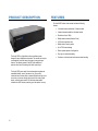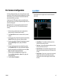
1
HDIP High Definition Network Video Recorder User Manual NV80 - 8 Channel Recorder NV160 - 16 Channel Recorder AvertX HDIP High Definition Network Video Recorder Operations Manual Manual Edition 32223AD – APRIL 2014 ©2014, AvertX All Rights Reserved No part of this document may be reproduced by any means, electronic or mechanical, for any purpose, except as expressed in the Software License Agreement. AVERTX shall not be liable for technical or editorial errors or omissions contained herein. The information in this document is subject to change without notice. The information in this publication is provided “as is” without warranty of any kind. The entire risk arising out of the use of this information remains with recipient. In no event shall AVERTX be liable for any direct, consequential, incidental, special, punitive, or other damages whatsoever (including without limitation, damages for loss of business profits, business interruption or loss of business information), even if AVERTX has been advised of the possibility of such damages or whether in an action, contract or tort, including negligence. This software and documentation are copyrighted. All other rights, including ownership of the software, are reserved to AvertX. AVERTX, and AvertX, are registered trademarks of AVERTX in the United States and elsewhere; Windows is a registered trademarks of Microsoft Corporation. All other brand and product names are trademarks or registered trademarks of the respective owners. The following words and symbols mark special messages throughout this guide: WARNING: Text set off in this manner indicates that failure to follow directions could result in bodily harm or loss of life. CAUTION: AVERTX 2 Text set off in this manner indicates that failure to follow directions could result in damage to equipment or loss of information. IMPORTANT SAFEGUARDS 12. Disc Tray – Keep fingers well clear of the disc tray as it is closing. Neglecting to do so may cause serious personal injury. 1. Read Owner’s Manual – After unpacking this product, read the owner’s manual carefully, and follow all the operating and other instruction 13. Burden – Do not place a heavy object on or step on the product. The object may fall, causing serious personal injury and serious damage to the product. 2. Power Sources – This product should be operated only from the type of power source indicated on the label. If not sure of the type of power supply to your home or business, consult product dealer or local power company 14. Disc – Do not use a cracked, deformed, or repaired disc. These discs are easily broken and may cause serious personal injury and product malfunction. 3. Ventilation – Slots and openings in the cabinet are provided for ventilation and to ensure reliable operation of the product and to protect it from overheating, and these openings must not be blocked or covered. The product should not be placed in a built-in installation such as a bookcase or rack unless proper ventilation is provided or the manufacturer’s instructions have been adhered to. 4. Heat – The product should be situated away from heat sources such as radiators, heat registers, stoves, or other products that produce heat. 5. Water and Moisture – Do not use this product near water. 6. Cleaning – Unplug this product from the wall outlet before cleaning. Do not use liquid cleaners or aerosol cleaners. Use a damp cloth for cleaning. 7. Power Cord Protection – Power-supply cords should be routed so that they are not likely to be walked on or pinched by items placed against them, paying particular attention to cords at plugs, convenience receptacles, and the point where they exit from the product. 8. Overloading – Do not overload wall outlets, extension cords, or integral convenience receptacles as this can result in a risk of fire or electrical shock. 9. Lightning – For added protection for this product during storm, or when it is left unattended and unused for long periods, unplug it from the wall outlet. This will prevent damage to the product due to lightning and power line surges. 10. Object and Liquid Entry Points – Never insert foreign objects into the recorder, other than the media types approved by AvertX, as they may touch dangerous voltage points or short-out parts that could result in a fire or electrical shock. Never spill liquid of any kind on the product. 11. Accessories – Do not place this product on an unstable cart, stand, tripod, bracket, or table. The product may fall, causing serious personal injury and serious damage to the product. 15. Damage Requiring Service – Unplug the unit from the outlet and refer servicing to qualified service personnel under the following conditions: • When the power-supply cord or plug is damaged. • If liquid has been spilled, or objects have fallen into the unit. • If the unit has been exposed to rain or water. • If the unit does not operate normally by following the operating instructions. Adjust only those controls that are covered by the operating instructions as an improper adjustment of other controls may result in damage and will often require extensive work by a qualified technician to restore the unit to its normal operation. • If the unit has been dropped or the enclosure has been damaged. • When the unit exhibits a distinct change in performance – this indicates a need for service. 16. Servicing – Do not attempt to service this product as opening or removing covers may expose the user to dangerous voltage or other hazards. Refer all servicing to qualified personnel. 17. Replacement Parts – When replacement parts are required, be sure the service technician has used replacement parts specified by the manufacturer or have the same characteristics as the original part. Unauthorized substitutions may result in fire, electric shock or other hazards. 18. Safety Check – Upon completion of any service or repairs to this unit, ask the service technician to perform safety checks to determine that the unit is in proper operating condition. BATTERY EXPLOSION CAUTION STATEMENT CAUTION: Risk of Explosion if Battery is replaced by an Incorrect Type. Dispose of Used Batteries According to the Instructions. HANDLING MOISTURE CONDENSATION Please retain the original shipping carton and/or packing materials supplied with this product. To ensure the integrity of this product when shipping or moving, repackage the unit as it was originally received from the manufacturer. Moisture condensation damages the recorder. Read the following information carefully. Do not use volatile liquids, such as aerosol spray, near this product. Do not leave rubber or plastic objects in contact with this product for extended periods of time. Rubber or plastic objects left in contact with this product for extended periods of time will leave marks on the finish. When this product is brought directly from a cool location to a warm location. The top and rear panels of the unit may become warm after long periods of use. This is not a malfunction. When this product is used in a room where the temperature fluctuates. LOCATING When this product is used in a humid location. Moisture condensation occurs during the following cases: When this product is moved to a hot and humid location from a cool location. When this product is moved to a cool and humid location from a warm location. When this product is used near an air-conditioning unit vent Do not use the recorder when moisture condensation may occur. Place this unit on a level surface. Do not use it on a shaky or unstable surface such as a wobbling table or inclined stand. If this unit is placed next to a TV, radio, or VCR, the playback picture may become poor and the sound may be distorted. If this happens, place the recorder away from the TV, radio, or VCR. If the recorder is used in such a situation, it may damage discs and internal parts. Remove any CD discs, connect the power cord of the recorder to the wall outlet, turn on the recorder, and leave it for two to three hours. After two to three hours, the recorder will warm up and evaporate any moisture. Keep the recorder connected to the wall and moisture will seldom occur. CLEANING WARNING Use a soft dry cloth for cleaning. TO REDUCE THE RISK OF ELECTRICAL SHOCK, DO NOT EXPOSE THIS APPLIANCE TO RAIN OR MOISTURE. For stubborn dirt, soak the cloth in a weak detergent solution, wring well and wipe. Use a dry cloth to wipe it dry. Do not use any type of solvent, such as thinner and benzene, as they may damage the surface of the recorder. If using a chemical saturated cloth to clean the unit, follow that product’s instructions. MAINTENANCE This recorder is designed to last for long periods of time. To keep the recorder always operational we recommend regular inspection maintenance (cleaning parts or replacement). For details, contact the nearest dealer. 4 DANGEROUS HIGH VOLTAGES ARE PRESENT INSIDE THE ENCLOSURE. DO NOT OPEN THE CABINET. REFER SERVICING TO QUALIFIED PERSONNEL ONLY. CAUTION RACK MOUNT INSTRUCTIONS Elevated Operating Ambient – If installed in a closed or multi-unit rack assembly, the operating ambient temperature of the rack environment may be greater than room ambient. Therefore, consideration should be given to installing the equipment in an environment compatible with the maximum ambient temperature (Tma) specified by the manufacturer. Reduced Air Flow – Installation of the equipment in a rack should be such that the amount of airflow required for safe operation of the equipment is not compromised. Mechanical Loading – Mounting of the equipment in the rack should be such that a hazardous condition is not achieved due to uneven mechanical loading. Circuit Overloading – Consideration should be given to the connection of the equipment to the supply circuit and the effect that overloading of the circuits might have on over current protection and supply wiring. Appropriate consideration of equipment nameplate ratings should be used when addressing this concern. Grounding – Grounding of rack-mounted equipment should be maintained. Particular attention should be given to supply connections other than direct connections to the branch circuit (e.g. use of power strips). FCC STATEMENT INFORMATION TO THE USER: THIS PRODUCT HAS BEEN TESTED AND FOUND TO COMPLY WITH THE LIMITS FOR A CLASS A DIGITAL DEVICE PURSUANT TO PART 15 OF THE FCC RULES. THESE LIMITS ARE DESIGNED TO PROVIDE REASONABLE PROTECTION AGAINST HARMFUL INTERFERENCE WHEN THE EQUIPMENT IS OPERATED IN A COMMERCIAL ENVIRONMENT. THE PRODUCT GENERATES, USES, AND CAN RADIATE RADIO FREQUENCY ENTERGY, AND, IF NOT INSTALLED AND USED IN ACCORDANCE WITH THE MANUFACTURER’S INSTRUCTIO MANUAL, MAY CAUSE HARMFUL INTERFERENCE WITH RADIO COMMUNICATIONS. OOPERATION OF THIS PRODUCT IN A RESIDENTIAL AREA IS LIKELY TO CAUSE HARMFUL INTERFERENCE, IN WHICH CASE YOU WILL BE REQUIRED TO CORRECT THE INTERFERENCE AT YOUR OWN EXPENSE. THESE LIMITS ARE DESIGNED TO PROVIDE REASONABLE PROTECTION AGIANST HARMFUL INTERFERENCE IN A NON-RESIDENTIAL INSTALLATION. HOWEVER, THERE IS NO GUARANTEE THAT INTERFERENCE WILL NOT OCCUR IN A PARTICULAR INSTALLATION. IF THIS EQUIPMENT DOES CAUSE HARMFUL INTERFERENCE WITH THE RADIO OR TELEVISION RECEPTION, WHICH CAN BE DETERMINED BY TURNING THE EQUIPMENT OFF AND ON, YOU ARE ENCOURAGED TO TRY TO CORRECT THE INTERFERENCE BY ONE OR MORE OF THE FOLLOWING MEASURES. • • • • REORIENT OR RELOCATE THE RECEIVING ANTENNA. INCREASE THE SEPARATION BETWEEN THE EQUIPMENT AND RECEIVER. CONNECT THE EQUIPMENT TO AN OUTLET ON A CIRCUIT DIFFERENT FROM THAT TO WHICH THE RECEIVER IS CONNECTED CONSULT THE DEALER OR AN EXPERIENCED RADIO/TV TECHNICIAN FOR HELP. CAUTION: CHANGES OR MODIFICATIONS NOT EXPRESSLY APPROVED BY THE PARTY RESPONSIBLE FOR COMPLIANCE COULD VOID THE USER’S AUTHORITY TO OPERATE THE EQUIPMENT. THIS CLASS A DIGITAL APPARATUS COMPLIES WITH CANADIAN ICES-003. CET APPAREIL NUMÉRIQUE DE LA CLASSE B EST CONFORME À LA NORME NMB-003 DU CANADA. OPERATION OF THIS DEVICE IS SUBJECT TO THE FOLLOWING CONDITIONS: • • • • THIS DEVICE MAY NOT CAUSE HARMFUL INTERFERENCE. THIS DEVICE MUST ACCEPT INTERFERENCE RECEIVED, INCLUDING INTERFERENCE THAT MAY CAUSE UNDESIRABLE OPERATION. CABLES USED WITH THIS DEVICE MUST BE PROPERLY SHIELDED TO COMPLY WITH THE REQUIREMENTS OF THE FCC. ANY CHANGES OR MODIFICATIONS NOT EXPRESSLY APPROVED IN THIS MANUAL COULD VOID YOUR AUTHORITY TO OPERATE THIS EQUIPMENT. USERS OF THE PRODUCT ARE RESPONSIBLE FOR CHECKING AND COMPLYING WITH ALL FEDERAL, STATE, AND LOCAL LAWS AND STATUTES CONCERNING THE MONITORING AND RECORDING OF VIDEO AND AUDIO SIGNALS. AVERTX SHALL NOT BE HELD RESPONSIBLE FOR THE USE OF THIS PRODUCT IN VIOLATION OF CURRENT LAWS AND STATUTES. 6 TABLE OF CONTENTS PREFACE ...................................................................................................................................................................................................................................... 14 About this Guide ..................................................................................................................................................................................................... 14 Technician Notes .................................................................................................................................................................................................... 14 ONE: INTRODUCTION ................................................................................................................................................................................................................. 15 Product Description ................................................................................................................................................................................................ 16 Features ................................................................................................................................................................................................................. 16 Basic Setup ............................................................................................................................................................................................................ 17 Password Protection............................................................................................................................................................................................... 17 TWO: CONNECTIONS ................................................................................................................................................................................................................. 18 Front Panel ............................................................................................................................................................................................................. 19 Front Panel ...................................................................................................................................................................................................... 19 Rear Panel.............................................................................................................................................................................................................. 20 RevA Rear Panel (16-channel model shown).................................................................................................................................................. 20 RevB Rear Panel (16-channel model shown).................................................................................................................................................. 20 Remote Control ...................................................................................................................................................................................................... 21 Setting the Remote Controller ID..................................................................................................................................................................... 21 Unit ID and Remote Control Number........................................................................................................................................................ 21 Assign a unique Unit ID on the recorder................................................................................................................................................... 22 Set the number on the Remote Controller ................................................................................................................................................ 22 USB Mouse ..................................................................................................................................................................................................... 22 Right-Click Menu ...................................................................................................................................................................................... 22 Onscreen Menu Bar ................................................................................................................................................................................. 23 USB Keyboard ......................................................................................................................................................................................... 23 THREE: INSTALLATION .............................................................................................................................................................................................................. 25 Connection Guide ................................................................................................................................................................................................... 26 Power Setup .................................................................................................................................................................................................... 26 Monitor Setup .................................................................................................................................................................................................. 26 Connecting an IP Camera ............................................................................................................................................................................... 27 Connecting to a Network ................................................................................................................................................................................. 27 Connecting an Alarm/Sensor Input.................................................................................................................................................................. 27 Connecting a Relay Output ............................................................................................................................................................................. 27 Turning on the Recorder......................................................................................................................................................................................... 27 First Time Power On ....................................................................................................................................................................................... 27 Normal Power On ............................................................................................................................................................................................ 27 Turning off the Recorder......................................................................................................................................................................................... 27 FOUR: SETUP .............................................................................................................................................................................................................................. 28 Basic/Advanced Setup Mode.................................................................................................................................................................................. 29 Main Menu .............................................................................................................................................................................................................. 29 System ................................................................................................................................................................................................................... 30 Hard Drive Setup ............................................................................................................................................................................................. 30 Data Lifetime Setup .................................................................................................................................................................................. 30 Internal Disks ........................................................................................................................................................................................... 30 External Disks .......................................................................................................................................................................................... 30 Data Protection ........................................................................................................................................................................................ 31 Repair On Power Loss ............................................................................................................................................................................. 31 Language ........................................................................................................................................................................................................ 31 Date/Time ........................................................................................................................................................................................................ 31 Network Time Protocol Setup................................................................................................................................................................... 31 Daylight Saving Time Setup ..................................................................................................................................................................... 31 Mouse Sensitivity ............................................................................................................................................................................................ 32 RS485 Setup ................................................................................................................................................................................................... 32 Key Beep ......................................................................................................................................................................................................... 32 Load Factory Default ....................................................................................................................................................................................... 32 Import Configuration ........................................................................................................................................................................................ 32 Export Configuration ........................................................................................................................................................................................ 32 Basic/Advanced Setup Mode .......................................................................................................................................................................... 32 Shutdown ........................................................................................................................................................................................................ 32 Power Key Privilege ................................................................................................................................................................................. 33 Auto Restart ............................................................................................................................................................................................. 33 8 Users ...................................................................................................................................................................................................................... 33 Password Protection ....................................................................................................................................................................................... 33 Auto Logout ..................................................................................................................................................................................................... 34 Account Setup ................................................................................................................................................................................................. 34 Configuring and Modifying a User Account .............................................................................................................................................. 34 Permissions Setup .......................................................................................................................................................................................... 34 Load Default Settings ...................................................................................................................................................................................... 35 Network .................................................................................................................................................................................................................. 35 System Name .................................................................................................................................................................................................. 35 Camera Info..................................................................................................................................................................................................... 35 LAN Setup ....................................................................................................................................................................................................... 36 DHCP ....................................................................................................................................................................................................... 36 Network Restart ....................................................................................................................................................................................... 36 Web Port ......................................................................................................................................................................................................... 36 DDNS Setup .................................................................................................................................................................................................... 36 PoE PnP .......................................................................................................................................................................................................... 37 PoE Power Limitation ...................................................................................................................................................................................... 37 PoE Status ...................................................................................................................................................................................................... 37 E-Mail Management ........................................................................................................................................................................................ 37 Cameras ................................................................................................................................................................................................................. 38 IP Camera Select ............................................................................................................................................................................................ 38 IP Camera Name ............................................................................................................................................................................................. 38 IP Camera Hidden ........................................................................................................................................................................................... 39 Enable PnP ..................................................................................................................................................................................................... 39 Device Search ................................................................................................................................................................................................. 39 Hostname/IP.................................................................................................................................................................................................... 39 Model............................................................................................................................................................................................................... 39 Connection Setup ............................................................................................................................................................................................ 39 Device Setup ................................................................................................................................................................................................... 40 Image Settings ......................................................................................................................................................................................... 40 Stream Settings ........................................................................................................................................................................................ 40 Activated.......................................................................................................................................................................................................... 41 32223AD 9 Status .............................................................................................................................................................................................................. 41 Copy Settings .................................................................................................................................................................................................. 41 Schedule ................................................................................................................................................................................................................ 42 Global Recording Configuration ...................................................................................................................................................................... 42 Schedule Setup ............................................................................................................................................................................................... 42 Day and Night Schedule........................................................................................................................................................................... 42 Weekend Schedule .................................................................................................................................................................................. 42 Per Camera Configuration ............................................................................................................................................................................... 43 Alarms .................................................................................................................................................................................................................... 43 Per Channel Configuration .............................................................................................................................................................................. 44 Channel Select ......................................................................................................................................................................................... 44 Alarm In .................................................................................................................................................................................................... 44 Alarm Out ................................................................................................................................................................................................. 45 Video Loss Detection ............................................................................................................................................................................... 45 Motion Detection ...................................................................................................................................................................................... 45 Motion Detection Setup ............................................................................................................................................................................ 46 Event Trigger Preset ................................................................................................................................................................................ 46 Copy Event Settings ................................................................................................................................................................................. 46 Display .................................................................................................................................................................................................................... 47 VGA Resolution ............................................................................................................................................................................................... 47 Monitor Image Controls ................................................................................................................................................................................... 47 Monitor Dwell ................................................................................................................................................................................................... 47 Monitor Schedule ............................................................................................................................................................................................ 48 Date/Time Display ........................................................................................................................................................................................... 48 Show Camera Name ....................................................................................................................................................................................... 48 Show System Name in Live............................................................................................................................................................................. 48 Info ......................................................................................................................................................................................................................... 49 Software Upgrade ........................................................................................................................................................................................... 49 Update the Firmware on Your HDIP Recorder ......................................................................................................................................... 49 Remotely Update the Firmware on Your HDIP Recorder ......................................................................................................................... 50 FPGA Upgrade Via Local Device .................................................................................................................................................................... 50 System Log ..................................................................................................................................................................................................... 50 10 Operation Log.................................................................................................................................................................................................. 50 FIVE: OPERATION ....................................................................................................................................................................................................................... 51 Login....................................................................................................................................................................................................................... 52 Change the Admin Password .......................................................................................................................................................................... 52 Adjust Permission Level Requirement for Menu Access ................................................................................................................................. 52 Live Display ............................................................................................................................................................................................................ 53 Channel Selection ........................................................................................................................................................................................... 53 Display Mode ................................................................................................................................................................................................... 53 Sequence ........................................................................................................................................................................................................ 53 Presets ............................................................................................................................................................................................................ 53 Creating a Camera Position Preset .......................................................................................................................................................... 53 Calling a Camera Position Preset ............................................................................................................................................................ 54 Calling a Camera Tour ............................................................................................................................................................................. 54 Non-Decoding Mode ....................................................................................................................................................................................... 54 Search .................................................................................................................................................................................................................... 55 Search by Time ............................................................................................................................................................................................... 55 Review Calendar to Select Date and Time to Play ................................................................................................................................... 56 Search By Event.............................................................................................................................................................................................. 56 Backup/Export VIDEO ............................................................................................................................................................................................ 57 Backup Viewer........................................................................................................................................................................................................ 58 Snapshot ......................................................................................................................................................................................................... 58 4:3 ................................................................................................................................................................................................................... 58 Save or Load Settings ............................................................................................................................................................................................ 59 Export Configuration ........................................................................................................................................................................................ 59 Import Configuration ........................................................................................................................................................................................ 59 SIX: REMOTE CONNECTION ...................................................................................................................................................................................................... 60 Introduction to Remote Connection ........................................................................................................................................................................ 61 Network Basics................................................................................................................................................................................................ 61 Networking at a Glance ............................................................................................................................................................................ 61 Remote Connection Setup ..................................................................................................................................................................................... 62 LAN Setup ....................................................................................................................................................................................................... 62 32223AD 11 Static IP Address ...................................................................................................................................................................................... 62 DDNS Setup .................................................................................................................................................................................................... 63 Port Forwarding ............................................................................................................................................................................................... 63 Configure Your Router ............................................................................................................................................................................. 63 Configure Your Recorder ......................................................................................................................................................................... 64 Establishing a Connection with a Remote Workstation ................................................................................................................................... 64 Connecting to the Recorder on a Local Area Network ............................................................................................................................. 64 Connecting to the Recorder from a Remote Location .............................................................................................................................. 65 Accessing your AvertX IP Camera .................................................................................................................................................................. 65 Connecting to the Recorder on a Local Area Network ............................................................................................................................. 65 Connecting to the Recorder From a Remote Location ............................................................................................................................. 66 Using Mobile Apps .......................................................................................................................................................................................... 66 Downloading an App ................................................................................................................................................................................ 66 Using the Remote Software .................................................................................................................................................................................... 67 Channel Select ................................................................................................................................................................................................ 67 Record ............................................................................................................................................................................................................. 67 Camera Display Divisions................................................................................................................................................................................ 67 Bandwidth Select............................................................................................................................................................................................. 67 Remote Software Live Screen ......................................................................................................................................................................... 68 Download Backup Viewer................................................................................................................................................................................ 69 Live .................................................................................................................................................................................................................. 69 Search ............................................................................................................................................................................................................. 69 Playback Recorded Video ........................................................................................................................................................................ 69 Download a Segment of Recorded Video ................................................................................................................................................ 69 Configuration (Setup Menu) ............................................................................................................................................................................ 70 Event List......................................................................................................................................................................................................... 70 View an Event in Playback ....................................................................................................................................................................... 70 Download an Event to your Computer...................................................................................................................................................... 70 Snapshot ......................................................................................................................................................................................................... 70 4:3 ................................................................................................................................................................................................................... 71 Health .............................................................................................................................................................................................................. 71 PTZ ................................................................................................................................................................................................................. 71 12 AvertX Remote for Mac .......................................................................................................................................................................................... 72 Product Description ......................................................................................................................................................................................... 72 Features .......................................................................................................................................................................................................... 72 System Requirement ....................................................................................................................................................................................... 72 Downloading AvertX Remote .......................................................................................................................................................................... 72 Using AvertX Remote ...................................................................................................................................................................................... 72 Connect to Your Recorder........................................................................................................................................................................ 72 Editing a Recorder.................................................................................................................................................................................... 72 Deleting a Recorder ................................................................................................................................................................................. 73 Viewing Multiple Recorders ...................................................................................................................................................................... 73 Viewing Live Video ................................................................................................................................................................................... 74 Playback................................................................................................................................................................................................... 75 Event Search ............................................................................................................................................................................................ 75 APPENDIX A: ADDITIONAL CAMERA CONFIGURATION ........................................................................................................................................................ 76 Plug’N’Play and Power over Ethernet..................................................................................................................................................................... 77 Using ONVIF Cameras from Other Manufacturers ......................................................................................................................................... 77 Using an External PoE Switch ......................................................................................................................................................................... 78 Connect Your Camera and PoE Switch to Your Local Network ............................................................................................................... 78 Connect Your Camera to Your Recorder Over the Network..................................................................................................................... 78 32223AD 13 PREFACE ABOUT THIS GUIDE This manual is to be used as a reference for setting up the AvertX HDIP network video recorder, and for troubleshooting any problems you might encounter. If you are unable to solve any problems with this guide, please contact AvertX support, or an authorized technician to repair the unit. AvertX reserves the right to make changes to the products represented by this manual without notice. The following text and symbols mark special messages throughout this guide: Note Notes indicate topics of interest intended to better your understanding of this AvertX product. TECHNICIAN NOTES Warning Only authorized technicians trained by AvertX should attempt to repair this recorder. All troubleshooting and repair procedures indicated in this manual are to be used only for reference and minor repairs. Due to the complexity of the device, no end-user should attempt to make component repairs or modifications to any printed wiring board. Improper repairs can create a safety hazard. Any indications of component replacement or printed wiring board modifications may void any warranty. Warning To reduce the risk of electrical shock or damage to the equipment: • Do not disable the power grounding plug. The grounding plug is an important safety feature. • Plug the power cord into a grounded electrical outlet that is easily accessible at all times. • Disconnect the power from the recorder by unplugging the power cord either from the electrical outlet or the recorder. Caution To properly ventilate your AvertX system, you must provide at least 3 inches (7.6 cm) of clearance at the front and back of the recorder. 14 ONE: INTRODUCTION Product Description Features Basic Setup Password Protection 3222AD 15 PRODUCT DESCRIPTION FEATURES The AvertX HDIP network video recorder includes the following features: The AvertX HDIP is a high-definition video surveillance system designed for easy installation and operation. This recorder can be put to use immediately, and offers easy-to-use search, setup, and export features. The operating system of the HDIP offers stability and protection from viruses—protecting itself while it protects you. The AvertX HDIP comes ready for fast and seamless integration and unparalleled stability, security, and ease of use. Your security investment has never been easier to maintain. Multiple users (up to four at one time) may connect through the internet for live viewing, digital search, and even camera control. With the latest advancements included in the HDIP software, searching your video archive is a snap. 16 • 16 network channels available on 16-channel models • 8 network channels available on 8-channel models • Resolutions of up to 1080p • Multiple search methods (Calendar, Event) • H.264 video compression only • Multiple levels of security access • Up to 6TB of internal storage • Remote system operation & configuration • Day, night, or weekend scheduling • Continuous, motion-activated, and sensor-activated recording BASIC SETUP With these basic quick start instructions the recorder is configured to record, can be accessed remotely over the local network, and secured against unauthorized logins. For further instructions, setup details, remote access, and configuration see the other chapters in this manual. Note To access the recorder using your mobile phone or computer at another location, you must configure the recorder for remote connection. See the Remote Connection chapter of this manual for more information. PASSWORD PROTECTION The HDIP network video recorder does not require user authentication by default. However, AvertX strongly recommends securing your HDIP recorder by setting up user authentication. 1. Right-click the Live screen and then click Menu. 2. Click System and set Basic/Advanced Setup Mode to Advanced. 3. Click Users. 4. Set Password Protection to On, and then click Account Setup to change admin and user passwords, if needed. 1. Establish necessary cable connections and turn on the recorder. • Default Username: admin 2. Right-click the Live screen and then click Menu. • Default Password: 1234 3. Click System. 4. Click Date/Time. 5. Verify or modify the date and time, then close the window. 6. Click Network. 7. Click LAN Setup. 8. DHCP is enabled (On) by default, if no changes are needed simply make a note of the IP address. 9. If the IP address needs to be static, set DHCP to Off, and then enter the IP Address, Netmask, Gateway, and DNS for the network. 10. Close LAN Setup. 11. Right-click to close Network. 12. Right-click to return to the Main Menu. 13. Right-click again to return to the Live screen. 3222AD 17 TWO: CONNECTIONS Front Panel Rear Panel Remote Control 18 FRONT PANEL Front Panel Alarm LED USB Record LED Network LED 3222AD Power Button/ Power LED Indicator 19 REAR PANEL AvertX has produced two versions of HDIP recorders, which can be differentiated by their part numbers. To find the part number of your recorder, locate the product sticker, either on the side of your recorder, or on the bottom. If your part number contains the letter A, refer to the RevA connection diagram. If your part number contains the letter B, refer to the RevB connection diagram. RevA Rear Panel (16-channel model shown) Network Camera Ports Connection LEDs VGA Port Power Alarm I/O HDMI Port USB LAN Network Port Cooling Fan eSATA RevB Rear Panel (16-channel model shown) Network Camera Ports VGA Port HDMI Port LAN Network Port 20 Power Alarm I/O USB Cooling Fan Setting the Remote Controller ID REMOTE CONTROL Unit ID and Remote Control Number To use the included remote controller, each recorder needs a unique Unit ID number that corresponds with a Remote Control number. Use this for reference. Unit ID Remote Control ID 224 01 225 02 226 03 227 04 228 05 229 06 230 07 Exit / Escape 231 08 Export 232 09 Fast Forward 233 10 234 11 235 12 236 13 237 14 238 15 239 16 DVR select Channel selection Direction arrows Enter Search Sequence Menu Reverse Play Pause The Mighty Squirrel Contr oller 3222AD 21 Assign a unique Unit ID on the recorder 1. Right-click on the Live screen and click Menu. 2. Click System. 3. Select Basic/Advanced Setup Mode and click Advanced. 4. Click RS485 Setup. 5. Select Unit ID and click Num. 6. Use the on-screen keyboard or a USB keyboard to assign an ID to your recorder. 7. Click OK. 8. Close RS485 Setup. 9. Right-click to return to the Main menu. 10. Right-click again to return to the Live screen. Note See the Unit ID and Remote Control Number table for additional reference. Set the number on the Remote Controller Press DVR SELECT on the remote controller and enter the corresponding Remote Control number to operate the recorder. For example, if the Unit ID is set to 225, press DVR SELECT on the remote controller and then press 2 immediately. Note 22 See the Unit ID and Remote Control Number table for additional reference. USB Mouse Your AvertX HDIP recorder comes with a USB mouse that can be connected to the USB port on the front or the rear panel of the recorder. The mouse allows you to use the mouse pointer to select and click menu items (instead of using the remote control). Using a USB mouse also allows access to two additional menu controls: a right-click menu, and the onscreen menu bar. Right-Click Menu While in Live Display mode, use the mouse to right-click anywhere on the screen to display the Right-Click Menu. Details on the options found in Menu selection can be found in the Menu section later in this manual; details on the remaining items can be found in the Operations section later in this manual. Onscreen Menu Bar The Onscreen Menu Bar will display two menu buttons when you move the mouse pointer over the Menu Bar: Channels and Function. The Channels menu allows you to click a channel number to display that channel full screen. USB Keyboard A USB keyboard can be connect to the USB port on either the front panel or the rear panel of the recorder. Having a USB keyboard connected will allow you to use the keyboard to enter alphanumeric characters (instead of using the arrow buttons on the remote controller to navigate the onscreen keyboard). Any time an onscreen keyboard is displayed (camera names, usernames, passwords, etc) the USB keyboard can be used to enter information. The Function menu provides all the same options as the Right-Click Menu in an icon format. All of these menu options lead to the same options as their corresponding front panel or remote control buttons. Details on the options found in Menu selection can be found in the Setup section later in this manual; details on the remaining items can be found in the Operations section later in this manual. 3222AD 23 Direct Control of Recorder Functions You can also use a USB keyboard to directly access functions on your recorder. Use this diagram and table for reference: EXIT PTZ BACKUP DISPLAY PLAY/ STOP SEQ PAUSE MENU SEARCH ESC F1 F2 F3 F4 F5 F6 F7 F8 CH1 CH2 CH3 CH4 CH5 CH6 CH7 CH8 CH9 CH10 1 2 3 4 5 6 7 8 9 0 ` CH11 CH12 CH13 CH14 CH15 CH16 Q W E R T Y TAB U I O F9 F10 - = P [ F11 F12 BACKSPACE ] \ ENTER CAPS LOCK A S D F G H J K L ; ‘ ENTER UP SHIFT CTRL 24 Z X C V ALT B N M , SPACE . / ALT SHIFT CTRL LEFT DOWN RIGHT Key Function Key Function Key Function Key Function Key Function ESC Exit F6 Pause 4 Channel 4 0 Channel 10 Y Channel 16 F1 PTZ F7 Menu 5 Channel 5 Q Channel 11 ENTER Enter F2 Backup F8 Search 6 Channel 6 W Channel 12 ↑ Up F3 Display 1 Channel 1 7 Channel 7 E Channel 13 ← Left F4 Play / Stop 2 Channel 2 8 Channel 8 R Channel 14 ↓ Down F5 Sequence 3 Channel 3 9 Channel 9 T Channel 15 → Right THREE: INSTALLATION Connection Guide Turning On the Recorder Turning Off the Recorder 3222AD 25 CONNECTION GUIDE Power Setup Monitor Setup The recorder has the following connections available to attach a monitor. WARNING: To reduce the risk of electrical shock or damage to the equipment: Do not disable the power grounding plug. The grounding plug is an important safety feature. If the electrical plug you are using does not have a ground plug receptacle contact a licensed electrician to have it replaced with a grounded electrical outlet. Plug the power cord into a grounded (earthed) electrical outlet that is easily accessible at all times. Disconnect the power from the recorder by unplugging the power cord either from the electrical outlet or the recorder. 26 HDMI Output To TV / Digital Display VGA Connect to an analog VGA Monitor Connect the monitor or monitors to the rear of the recorder using the cable supplied by the monitor manufacturer. Refer to the monitor manual for detailed information on how to set up and use it. Note The monitor must be capable of having a minimum screen resolution of 1024 x 768 and display colors of at least 32 Bit Connecting an IP Camera The AvertX HDIP network video recorder uses IP network cameras. To connect an IP camera, plug the network cable into the desired channel on the back of the recorder. The HDIP has a built-in PoE switch, which means that power is supplied to your camera over the network cable, so there is no need to plug a separate power supply into your PoEequipped camera. Note Note AvertX cameras use Power Over Ethernet (PoE), and will work when plugged into your recorder without any other equipment. If you are using IP cameras from another manufacturer, you may need a separate power supply if it is not a PoE camera. The AvertX HDIP supports PTZ (Pan/Tilt/Zoom) cameras from rd 3 Party ONVIF manufacturers. TURNING ON THE RECORDER First Time Power On 1. Connect cameras using the provided network cables. 2. Connect monitor cable. 3. Connect network cable if remote access will be needed. 4. Connect alarm inputs and relay outputs if needed. 5. Connect the power cable to the recorder. 6. Press the button on the front panel to turn on the recorder. Normal Power On 1. Connecting to a Network Use the RJ45 jack on the rear of the recorder to connect to your router, modem, or network switch. Do not use this port to connect to an IP camera. Connecting an Alarm/Sensor Input Press the power button on the front panel. TURNING OFF THE RECORDER 1. Right-click in the Live screen and click Menu. 2. Click System. 3. Click Shutdown. 4. Click Power Off. 5. Click Confirm. Connect wired alarm/sensor inputs to the Alarm In ports on the I/O connector. Connecting a Relay Output Connect wired relay outputs to the Alarm Out port on the I/O connector. 3222AD 27 FOUR: SETUP Basic/Advanced Setup Mode Main Menu System Users Network Cameras Schedule Alarms Display Info 28 BASIC/ADVANCED SETUP MODE Your AvertX recorder can be set to either Basic or Advanced Setup Mode. Basic Setup Mode allows you to make a limited number of changes to the configuration. The instructions in this manual refer to the configuration settings available in Advanced Setup Mode. If you are attempting to make changes and are unable to find the menu items listed in these instructions, make sure that your recorder is operating in Advanced Setup Mode. To enable Advanced Setup Mode, follow these instructions. 1. Right-click the Live screen and click Menu. 2. Click System. 3. Select Basic/Advanced Setup Mode and click Advanced. MAIN MENU The following items can be configured in Basic Setup Mode: 3222AD • Hard Drive Setup • Date/Time • Load Factory Default • Import Configuration • Basic/Advanced Setup Mode • Shutdown • Account Setup • LAN Setup • Cameras • Schedule Setup • Event Icon • Event Duration • VGA Resolution • Date/Time Display • Software Upgrade • System Log Use this menu to configure all of the recorder settings, schedule recording, configure the alarms, set up user access, networking, display and system options. To access the menu, right-click on the Live screen and click Menu. If prompted, enter your admin password. 29 SYSTEM Use the System menu to configure the date and time and the unit name; to export, import, or reset system configurations, and restart or shutdown the recorder. Data Lifetime Setup Data Lifetime Setup allows you to limit how long your video is saved; by day, by channel, or the overall (general) life of the data. 1. Click Data Lifetime Setup. 2. Click Data Lifetime Mode and select your desired mode for data storage (General, By Day, or By Channel). 3. If you have chosen General mode, click Data Lifetime, and then use the on-screen keyboard or a USB keyboard to type the number of days to store your data. 4. If you have chosen By Day mode, click Data Lifetime By Day and determine the number of days to save data for each day of the week. 5. If you have chosen By Channel mode, click Data Lifetime By Channel and select the number of days to save data from each camera channel. 6. Close Data Lifetime Setup. Internal Disks Hard Drive Setup This option allows you to view and format the internal hard drives in the recorder. To view the size, available space and recording time on your hard drive, as well as to how your video and data are saved to the disk, click Hard Drive Setup. 1. Click Internal Disks. 2. To view the information for your hard drives, click the Detail column for the drive you want to view and select Yes. Total Size – This is the total size of all hard drives. 3. To format or repair your drive, click Action and select your desired action. 4. Close Internal Disks. Free Size – This is the available storage space on the hard drive. Avail. Rec Time – Your AvertX HDIP is set up for circular data storage, which means that new video will record over old video after a certain period of time. Est. Rec Period – This indicates an estimated amount of time you can record. 30 External Disks This option is not used with the hardware associated with the RevB (AVX-NV80-P2B or AVX-NV160-P2B) HDIP models. Data Protection This option allows you to lock the data of specified alarm events. Event video protected here will not be deleted or overwritten. 1. Click Data Protection. 2. Select your desired alarm events, listed by date and time, and click Lock, and then select Yes to lock the events. 3. Close Data Protection. Repair On Power Loss When set to On, this function performs a deep scan of the hard drives any time the recorder restarts after power loss. Language To choose the language for your recorder, click Language and select your desired language. The default language is English. Date/Time This option allows you to adjust the date, time, time zone, the format of the date and time displays, as well as to set up for daylight savings time or to use a Network Time Protocol. Network Time Protocol Setup Using a network time protocol allows you to ensure that your recorder is keeping accurate time in coordination with other time-sensitive devices. This is ideal if you are using multiple recorders in multiple locations and plan on accessing them remotely. This function is only available when the Time Zone function is set to On and if the recorder is connected to the Internet. 1. In the Date/Time menu, click Network Time Protocol Setup. 2. Type the IP address of your desired NTP Server. The default server is time-nw.nist.gov. 3. Set Automatically Time Sync to On. 4. When desired, you can manually sync with the NTP server by clicking Manual Time Sync. 5. Close Network Time Protocol Setup. 6. Close Date/Time to return to the System menu. Daylight Saving Time Setup This option allows you to turn Daylight Saving Time On or Off. You can also manually select the date and time when Daylight Saving Time will start and end; as well as specify the amount of time shift that should be applied. 1. In the Date/Time menu, click Daylight Saving Time Setup. 2. Click Daylight Saving Time and select On. To set the Date, Time, Time Zone, Date/Time Display, Date Display Mode, and Time Display Mode, click Date/Time and use your mouse to adjust the values. 3. Adjust the DST Start settings to the appropriate date and time to start Daylight Savings Time. 4. Adjust the DST End settings to the appropriate date and time to end Daylight Savings Time Note Changing the date or time after initial configuration, requires formatting the hard drive(s) to avoid data mismatch. 5. Adjust DST Bias to the appropriate time adjustment for Daylight Savings Time. 6. Close Daylight Saving Time Setup. Note In the United States, the Pacific Time Zone is -8:00, the Mountain Time Zone is -7:00, the Central Time Zone is -6:00, and the Eastern Time Zone is -5:00. 3222AD 31 Mouse Sensitivity Set the sensitivity of your mouse. The lower the sensitivity setting, the slower the mouse pointer will move. The default sensitivity setting is 70%. RS485 Setup RS485 Setup allows you to configure the Unit ID for remote controller communication. The other setting refer to RS485 bus and are note used with this system/ Key Beep By default, Key Beep is set to Off. It may also be set to On, providing audio feedback when you click menu items. Load Factory Default To reset your recorder to the factory default settings, click Yes. Click Yes again to continue. The recorder will restart with the factory default settings. Import Configuration You can import configurations from another HDIP recorder, or from a saved backup from your recorder, using a USB drive. 32 1. Plug a USB drive with a saved configuration file into a USB port and click Import Configuration. 2. Click the Configuration and select Yes. 3. Click Yes to continue. 4. Press ENTER or click the mouse to continue. 5. Your recorder will restart with your imported settings. Export Configuration You can export configurations from your HDIP recorder to backup settings, or for use in another HDIP recorder using a USB drive. 1. Plug a USB drive into the USB port and then click Export Configuration. 2. Click Destination. 3. Choose the USB drive you want to export your configuration to and select Yes. 4. Click File Name. 5. Use the on-screen keyboard or a USB keyboard to type a name for the file and then click OK. 6. Click Export. 7. Click Confirm. 8. Press any key or click Close to continue. 9. Close the Export Configuration window. Basic/Advanced Setup Mode You can switch recorder to Advanced Setup Mode by selecting Basic/Advanced Setup Mode and clicking Advanced. Advanced mode gives you access to the advanced settings of your recorder. Shutdown The Shutdown menu allows you to Power Off or Restart your recorder. You can also set the Power Key Privilege and Auto Restart configurations if desired. Power Key Privilege This option defines what prompts will be displayed when the power button is held down for five seconds. There are four options to choose from: • Auth – Users will be prompted to log in with an authorized account to shut down the recorder (the Password Protection option, found in the Users menu, must also be enabled). Enabling the Auth option will also enable the Confirm option. • Confirm – When users shut down the recorder, a message will appear asking them to confirm the shutdown. • Direct – The recorder will automatically shut down without any prompt or confirmation. • Disable – This option disables any shutdown option via use of the power button; leaving the Shutdown menu option as the only way to turn the recorder off. USERS The Users menu allows you to manage password protection, user accounts, passwords, and permissions settings. The HDIP network recorder provides eight built-in user accounts. You can customize the username, password, and privilege level for seven of these accounts. The preconfigured admin account has a permanently set username and privilege, but you can change the password. Auto Restart Set your recorder to restart either every day or weekly by selecting the day you want the recorder to restart. Once Auto Restart is enabled, you can choose the time of day you want the recorder to restart. Note If you have customized your camera settings and want to use Auto Restart, ensure that PnP is set to Off. This will prevent your recorder from overwriting your cameras settings when it restarts. Password Protection Password Protection allows you to require username and password authentication to access menu functions. The option is set to Off by default, meaning username and password are not required to access any menu functions. Change this setting to On to require authentication to access the recorder. Default Administrator Username: admin Default Administrator Password: 1234 3222AD 33 Auto Logout You can configure your recorder to automatically log out a user after a specified period of inactivity. Click Auto Logout and select the number of seconds of inactivity you want to elapse before the recorder logs the user out. You can also choose Disable to turn off this function. Account Setup Account Setup allows you to set up or modify user accounts, including customizing the username, password, and privilege level, or even disable an account. Configuring and Modifying a User Account 1. In the Account field, select the user account you want to configure. To change the name of the user, click Edit and use the on-screen keyboard or a USB keyboard to type the new user name. Note The username is case sensitive and requires a minimum of four characters. Permissions Setup Permissions Setup allows you to modify the privilege level required to access menu options and features of the recorder. To enable privilege requirements for any option, set it to a selected level: 1 through 8. Users will be able to access functions that are equal to or less than their set privilege level. No username will be required to access any function set to Disable. These functions can be configured for privilege requirements: • Playback/Search • Hidden Camera • PTZ Control • Live Operation • Export Data • Menu Access • System Setup • User Management • Network Setup • Camera Setup • Schedule Setup 2. Click OK. • Alarms Setup 3. Click Edit in the Password field and use the on-screen keyboard or a USB keyboard to type the new password. • Display Setup • System/Version Information Note The default password for a user account is 4321. Note Passwords require a minimum of four characters; maximum of eight characters. Note 34 4. Click Privilege and select the privilege level for this user (Level 1 ~ Level 8). Level 1 has the lowest authority, and Level 8 has full administrative authority. 5. Click Save. 6. Repeat as necessary, selecting user2 through user7 on step 2. The Menu Access option cannot be set to Disable. Load Default Settings NETWORK Load Default Settings allows you to reset all Users menu settings to factory defaults. Use the Network menu to configure your network communication options. 1. Click Load Default Setting and select Yes. For more information about using your HDIP recorder with a network please refer to the Remote Connection chapter of this manual. 2. Click any key to continue. Note ALL customized usernames and configurations will be lost, and cannot be recovered. Note This reset only affects options customized within the Users menu. Caution There is no confirmation message; selecting Yes will instantly reset Users menu settings. System Name Name your HDIP recorder in order to be able to identify it when accessing it remotely. 1. Click System Name. 2. Use the on-screen keyboard or a USB keyboard to type a name for your HDIP recorder. 3. Click OK. Camera Info This option allows you to view the format, resolution, frame rate and bandwidth of each camera on your system. 3222AD 35 LAN Setup LAN Setup allows you to configure the basic network settings for Ethernet communication. Consult a network administrator if you are not familiar with basic network configuration, or not familiar with the network you will be connecting to the recorder. To access this menu, click LAN Setup. DHCP DHCP allows you to enable or disable DHCP (Dynamic Host Configuration Protocol). By default DHCP is set to On and will attempt to obtain a dynamic IP address automatically. DHCP must be set to Off to allow editing of the IP, Netmask, Gateway, and DNS fields. • IP – Specify a unique IP address for your recorder. • Netmask – Specify a subnet mask of the network you are connecting to the recorder. • Gateway – Specify the default gateway of the network you are connecting to the recorder. • DNS – Specify the DNS of the network you are connecting to the recorder. Network Restart To disconnect and immediately establish a new network connection, click Network Restart and select Yes. Web Port To access your recorder from outside your local network, your router will use the web port of your recorder. The default port is 80. If you change the web port on the recorder, you must also configure your router to forward information to the same port number. See instructions for Port Forwarding in the Remote Configuration chapter. 1. Click Web Port. 2. Click Num and use the on-screen keyboard or a USB keyboard, or use the up and down arrow buttons to type or select the number you want to assign to your port. DDNS Setup To access your recorder from outside your local network, the recorder needs a static IP address. Most internet providers do not supply this, but a Dynamic Domain Naming System (DDNS) can solve this problem. Detailed instruction for DDNS setup, including the information for your Host Name, DDNS Account, and DDNS password can be found on the Dynamic Domain Naming System (DDNS) Installation and Activation insert included in your HDIP packaging. 1. Click DDNS Setup. 2. Click Enable DDNS and select On. 3. Type the Host Name, DDNS Account, and DDNS Password in the appropriate fields. 4. Click Send/Update and select Yes. 5. Once the update is complete, the host name field will automatically complete the full host name. Note 36 Port forwarding must also be configured on the router to allow remote access to the recorder from an offsite location. PoE PnP Power Over Ethernet Plug ‘n’ Play (PoE PnP) allows your recorder to supply power to your cameras over the Ethernet cables used to connect them to the system. It also allows your recorder to automatically detect and record new cameras as they are added to your system. To enable this feature, click PoE PnP and select Yes. PoE Power Limitation E-Mail Management Your HDIP recorder can send you messages via e-mail, alerting you of alarm events. Messages can be sent to up to three different addresses. Due to the volume of e-mails, AvertX recommends setting up a specific e-mail address to receive only these alarm messages. 1. Select which email account you are configuring in E-Mail Select (1, 2, or 3). 2. Click E-Mail Activate and select Off. This option allows you to limit the amount of power sent to your cameras over the Ethernet connection. The default setting is 175W. To change the setting, follow these instructions. Note Warning Do not change this setting unless instructed to do so by AvertX technical support. 3. Using the on-screen keyboard or a USB keyboard, type the E-mail Address you want to receive alert messages. 4. To include a video file with the alert message, click E-Mail Video Attachment and select On. When you are finished making your changes, set E-mail Activate to On. 1. Click PoE Power Limitation. 2. Click Num. 5. Click Event/Alarm Selection. 3. Using the on-screen keyboard or a USB keyboard, type in the amount of power, between 30 and 175 watts, you want to be transmitted over the Ethernet cables. 6. Choose what kinds of alarm events to be notified about by clicking on them and selecting Yes or No. 4. Click OK. PoE Status Click PoE Status to view the Port, Link, power consumption, and MAC address of each camera on your system. 3222AD • Motion Detection • Video Loss • Alarm Trigger • System Fan • Disk Error 7. Once you have selected the types of alarms to be notified about, close Event/Alarm Selection. 8. Click SMTP Server Setup. 37 Note 9. An SMTP server makes it possible for your recorder to send e-mail messages. You MUST have an SMTP server in order for the e-mail function of the HDIP system to work. If you are unsure of the information for your SMTP server, contact your internet provider. CAMERAS Use the CAMERAS menu to manually connect cameras and configure camera channel settings; including camera name, camera settings, and stream settings. In the SMTP Server Setup window, set Email Via SMTP to On. 10. Type your desired SMTP Server, SMTP Port (the default is 25), SMTP Account, and SMTP Password into the appropriate fields. 11. Set Use SSL Connection to On or Off as desired. Note Secure Sockets Layer (SSL) is an added layer of encryption. Use this option for added security for your alarm alert e-mails. 12. Close SMTP Server Setup. 13. Set E-mail Activate to On. 14. Repeat for up to two more e-mail recipients. 15. Close E-Mail Management. IP Camera Select For each set of instructions in this section, you will need to select a specific camera channel to configure. To select a channel, click IP Camera Select and then click the channel you want to configure. IP Camera Name You can assign each camera a name by clicking IP Camera Name and using the on-screen keyboard or a USB keyboard to type in the name. AvertX recommends choosing a name that is descriptive of the location of the camera, such as “Front Lobby,” or “Loading Dock.” 38 IP Camera Hidden Enabling this function will hide the camera from view in the Live screen. The camera footage will continue to be saved to the recorder and can be accessed by users with the proper privilege level. Enable PnP Use this function to enable Plug ‘n’ Play (PnP). Setting this to On allows the recorder to recognize the camera and begin recording video immediately without manually entering an IP address for each camera. If PnP is On, the cameras are reset to their default settings. If you have custom camera settings, set Enable PnP to Off. Note You can use Connection Setup to control what functions of your camera your HDIP unit has access to, as well as set up the kind of compression format the camera streams to the recorder, enable dual streams, and configure PTZ settings if the camera is a PTZ camera. 1. If you set Enable PnP to Off, you will need to manually enter the IP addresses of the cameras on your system. Click Device Search to view the brand, model, and IP address of each camera on your network. Write this information down for later use. Click on a camera to select it for the current camera channel. Hostname/IP Click Hostname/IP and type the IP Address of your camera if it is not already entered. This is only necessary if Enable PnP is set to Off. Model To specify the make of the camera you are configuring, you must first deactivate the camera by clicking Activated and selecting Off. You can then click Model and select AvertX or ONVIF (if your camera is not an AvertX camera, but is ONVIF compliant). Once you have selected your model, turn your camera back on by click Activated and selecting Yes. To control which account on the camera you are accessing, click Account and type the account name using the on-screen keyboard or a USB keyboard. 2. Click Password and type the correct password for the account. 3. Choose the Management Port for your camera. The default port is 80. 4. Click Main Stream Setup to access configuration settings for the primary video stream from your camera. 5. Choose your desired compression in Streaming Format. 6. Click Advanced Streaming Options and select On. 7. Set the Streaming Index, Streaming Port, and Streaming Protocol as desired. 8. Close Main Stream Setup. 9. To set up a second stream, click Dual Stream Setup. Enable PnP will only function with AvertX cameras. Device Search 3222AD Connection Setup 10. Set the configurations for Dual Streaming Support, Dual Streaming Recording, Dual Steaming Format, Dual Streaming Index, Dual Streaming Port, and Dual Streaming Protocol. 11. If you are configuring a PTZ camera, click IP PTZ Protocol and select the protocol for your camera. Note The PTZ protocol selected on your recorder must be the same as the PTZ protocol for your IP PTZ camera. 12. If you are configuring an IP dome camera, click IP Dome ID and use the on-screen keyboard or a USB keyboard to set the ID. Note The Dome ID selected on your recorder must be the same as the Dome ID assigned to your camera. 39 Device Setup This option allows you to adjust the image quality and streaming settings on your cameras. Image Settings Exposure Settings Exposure Settings controls how much light enters your camera. It is necessary to change the Exposure Settings if you are working in a low light area or a very bright area. By default, the Exposure Settings are set to Auto Shutter. Select the appropriate Mode for your camera (Auto Shutter or Fixed Shutter), and then set the appropriate Auto Shutter Speed or Fixed Shutter Speed. White Balance Different light sources produce different colors of light, which can affect your image and make it seem too orange, too green, or too blue. Use the White Balance Settings to adjust the color temperature of your camera. WDR When a camera is aimed at a door, window, or shaded area where there is a lot of light in the background, details of the objects and people in the shade can be lost. Wide Dynamic Range (WDR) corrects for this and makes it possible to see all the detail in the shaded area while keeping the definition of the objects in the bright area. Set WDR to Low, Mid, or High depending on the amount of difference between the light and dark areas of the image. Noise Reduction Different exposure settings and lighting conditions can result in digital interference in your image, referred to as Noise, which looks like static on old televisions. To reduce noise, select the appropriate Noise Reduction level. Stream Settings Your AvertX cameras are capable of dual streaming, which means they can send two different streams of video at different resolutions. You can use the higher resolution for recording, and the lower resolution for viewing live video over the web to save bandwidth. You can adjust the following settings in Stream Settings. 1. Click White Balance and select Auto, Auto-Tracking White Balance (ATW), or Manual. • Video Rotation – Adjust your image if the camera is placed on a table, wall, or ceiling. 2. If you select Manual, adjust your Red (Rgain) and Blue (Bgain) levels. • Bit Rate – Set the data transmission speed for your camera. A lower compression will result lower image quality but a smaller file size and more bandwidth availability. • Frame Rate – Adjust the frame rate for your camera. A higher frame rate results in more bandwidth and less available storage space. • Stream 1 Settings and Stream 2 Settings – Adjust the resolution, Group of Pictures (GOP) settings, and transcoding settings of each stream. Note Set Enable H264 CBR Mode to VBR to provide the highest video quality for variable bit rates. Set this to CBR to transmit a constant bit rate. Picture Adjustment Settings Adjust the Brightness, Sharpness, Contrast, Saturation, and Hue of your image, as desired. IR Function IR Function is enabled when using a camera equipped with IR Illuminators. IR Illuminators enable the camera to see in very low light situations, and are set to Smart by default. • 40 Apply – To save your Stream Settings, click Apply. Rotate a Camera Video Image Copy Settings If your camera is installed on a wall or table top the image may appear to be upside down. Rotate the camera video image using the recorder interface to get a right-side-up image. You can copy the settings to be used on another channel. To do so, Enable PnP must be set to Off, and Activated must be set to No. Note 1. Click Copy Settings. 2. Select the channels you want to export the camera settings to. You cannot rotate the video image 90° to get a vertical image. Rotating the image 90° will stretch and distort the video image. To rotate the camera video image: 1. In the Cameras setup menu, click Device Setup, and then Stream Settings. 2. For Video Rotation, select the desired rotation type. • Normal transmits the image as the camera sees it. • Flip transmits the image backwards and upside down. • Mirror transmits a mirror image. • 180 Degree transmits the image upside down. 3. Click Confirm. 4. Set Activated to Yes. 5. Set PnP to On if desired. Activated This option allows you to turn your camera on or off. Click Activated and select Yes or No to activate or deactivate your camera. Note In order to control this option, Enable PnP must be set to Off. Status This option allows you to view the streaming format, resolution, frame rate, bandwidth and percentage of video loss for the selected camera. Note 3222AD To view this information, Activated must be set to On. 41 SCHEDULE Use the Schedule menu to configure quality and frame rate for normal and motion/event recording, and set up a recording schedule. Schedule Setup Schedule Setup allows you to define the start and end time for day, night, and weekend recording schedules. Day and Night Schedule You can set different qualities of recording for different times of day, depending on your needs. 1. Click Day Time Start and select the time to start Day Time recording as desired. 2. Click Day Time End and select the time to end Day Time recording as desired. 3. Repeat for Night Time Start and Night Time End. Weekend Schedule Global Recording Configuration Global Recording Configuration allows you to quickly configure universal record settings based on your needs. 42 1. Click Global Configuration. 2. Select the level of recording you want to occur for all cameras on your system. • Off – No preconfigured universal settings. Global Configuration must be set to Off to enable the Per Camera Configuration menu option. • Continuous – All camera channels on your system will record continuously at all times. • Motion/Event – All camera channels will record only when motion is detected or an alarm event occurs. If you intend to have a different recording schedule for a series of days, set a weekend schedule. 1. Click Weekend Schedule and select On. 2. Click Weekend Start and select the day of the week and the time to start weekend recording. 3. Click Weekend End and select the day of the week and the time to stop weekend recording. Per Camera Configuration Per Camera Configuration allows you to set the specific frame rate and image quality for each camera for normal recording and during an alarm event. Frame rate, given in Pictures Per Second (PPS) dictates how smooth video will look on your screen. ALARMS Use the Alarms menu to configure how the recorder will respond to alarm events. A high frame rate (30 PPS) captures motion very smoothly but uses more system resources. A low frame rate produces choppier video, but uses less recording space. Most applications do not require a continuous high frame rate of 30 PPS. A lower frame rate of 10-15 PPS is sufficient for most event recording. 1. Select each camera channel and set up the configurations for frame rate, quality for normal and event recording. 2. Click Camera Select and select the camera channel you want to configure. 3. Select the frame rates in Pictures Per Second for normal recording (Normal PPS) during Day, Night, and Weekend schedules. 4. Select the image quality in Kilobytes Per Second (kbps) for normal recording (Normal Qlty) during Day, Night, and Weekend Schedules. 5. Select the maximum frame rate to be recorded during an alarm event (Event Max PPS) for Day, Night, and Weekend Schedules. 6. Select the image quality to be transmitted during an event (Event Qlty) for Day, Night, and Weekend Schedules. 7. Select the kind of event (Event Act) that will trigger Event Recording (Motion, Alarm, Both, or None) for Day, Night, and Weekend Schedules. 8. 3222AD Close Per Camera Configuration. • Internal Buzzer – This enables an audible beep from the recorder when an alarm event occurs. • Event Icon – Set this to On to display a small icon on the live screen when an alarm event occurs. • Event Full Screen – Set this to On to enlarge the video feed from the camera sensing the alarm event to full screen on the live view. • Event Duration – Set the time, in seconds, for the duration of recorded video, alarm beep, and the alarm relay output functions after motion or alarm is trigged (5 seconds to 999 seconds). 43 Per Channel Configuration AI 1 ALARM I/O Sensor Per Channel Configuration allows you to configure alarm events for video loss and alarm inputs and outputs. Channel Select Door frame GND Magnet For each item in this section, select a specific camera channel to configure. Door Alarm In Use the wired alarm input to enable your recorder to detect alarm inputs. Select Normally Closed (N/C) if the circuit should be completed in normal circumstances. The alarm will be trigger when the circuit is open in this situation. If the circuit should be open in normal situations, select Normally Open (N/O). Example: Using a Sensor to Trigger Video Recording These steps outline the process of installing a sensor for a door that should normally be closed. In this scenario, your recorder will log Sensor events. To enable your HDIP recorder to record when the door is opened, you must also configure the recording Schedule to Motion/Event. Refer to the Schedule section of this manual for more information. Note 44 For more details about setting up your door contacts, please refer to documentation from your alarm manufacturer. Door sensor hardware can be purchased at many home improvement stores. 1. Follow the manufacturer instructions to attach your sensor hardware to the door. There should be two parts for each door sensor contact, one attached to the door itself, and the other attached to the door frame. 2. Connect the wire from one side of the door sensor contact to AI 1 on the Alarm I/O connection block on the rear of your recorder (see illustration).Connect the wire from the other side of the door sensor contact to GROUND on the Alarm I/O connection block on the rear of your recorder (see illustration). 3. Log in to your HDIP recorder as an administrator, and navigate to the Alarms menu, and then click Per Channel Configuration. 4. Set Alarm In to Normally Closed (N/C). 5. Close Per Channel Configuration, and then return to the Live screen. 6. Your HDIP recorder will log this Sensor event each time the door is opened. 7. To enable your HDIP recorder to record when the door is opened, you must also configure the recording Schedule to Motion/Event. Refer to the Schedule section of this manual for more information.. Alarm Out Use this to enable one or both of the alarm outputs on the recorder. Select A Only, B Only, A + B, or None. Note For more information about wiring an external alarm, please refer to the documentation for your alarm from your alarm manufacturer. Video Loss Detection Set this option to On to trigger an alarm when the video feed from a camera is lost. This can occur if the camera loses power, breaks, or if it is vandalized or tampered with. 3222AD Motion Detection Use this item to enable motion detection for the camera you have selected. You can enable motion detection during Day, Night, Day and Night, Weekend, Day and Weekend, Night and Weekend, or All schedules. Schedules are configured in the Schedule menu. When Motion Detection is enabled, the recorder will request motion detection information from the camera. All AvertX cameras have motion detection enabled by default, and the motion detection function on the camera can be configured using your HDIP recorder. Note Because the recorder itself does not perform any motion detection, you will need to separately configure motion detection on any manually-connected cameras. These include any non-AvertX cameras as well as cameras that are connected to your system using an external PoE switch. Consult your camera user manual for configuration instructions. 45 Motion Detection Setup Set up the motion detection area, detection level, and sensitivity level for each camera. Detected Area Setup To set a motion detection grid, click Detected Area Setup. A live view of the selected camera will display. Full-screen Motion Detection 1. To select the entire viewing area of the camera, right click and then click Select All, then Zone O1. 2. Right click again and click Confirm to save this setting. Event Trigger Preset Use this item to set a PTZ camera to move to a predefined point when an alarm event occurs. This function will only work with PTZ cameras. 1. Click Event Trigger Preset. 2. Click Num, and then assign the pre-configured preset for the camera to move to when an alarm event is triggered.. 3. Click OK. Copy Event Settings You can copy event settings from one camera and apply the settings to other camera channels. Small Area Motion Detection 1. To select only part of the viewing area of your camera, Use your pointer to click one corner of the area where you want motion to be detected. 1. Click Copy Event Settings. 2. Select the camera channels you want to copy these settings to. 2. Move your mouse to the opposite corner of the area where you want to detect motion and click again. 3. Click Confirm. 4. Click Exit. 3. Click Zone 01 to confirm this motion detection zone. 5. Close Per Channel Configuration. 4. Right-click and then click Confirm to save this setting. Detection Level Detection Level controls the amount of motion required for an alarm to be triggered. Use the on-screen keyboard, a USB keyboard, or the up and down arrow buttons to adjust the sensitivity. Default detection level is 10. This item sets the detection level for each sampling pixel; the smaller the value, the more sensitive it is Sensitivity Level Sensitivity Level defines how much of an area must change before a motion event is triggered. The default setting is 80. Setting Sensitivity Level to a higher value will make it easier for motion detection to trigger a motion event. When you have finished setting these configurations, close Motion Detection Setup. 46 DISPLAY Use the Display menu to change the video output display settings. Monitor Image Controls You can adjust the image on your monitor using the monitor image controls. To adjust a setting, click Num next to the item you want to adjust, and then set the number in the field to your desired setting. Monitor Brightness – Adjust the brightness of the monitor. Monitor Contrast – Adjust the contrast on the monitor. Monitor Chrominance – Adjust the color on the monitor. Monitor Dwell Monitor Dwell allows you to select the amount of time a camera or screen division will appear on the live screen when the display has been set to sequence (1 second – 120 seconds). VGA Resolution 1. Click Monitor Dwell. 2. Click Num and use the on-screen keyboard or a USB keyboard to enter the amount of time – OR – use the up and down arrow buttons to select the number of seconds for the dwell. VGA Resolution allows you to change the screen resolution for your VGA or HDMI monitor. Available options are 1024x768, 1280x1024, 720p and 1080p. Click VGA Resolution and select the appropriate resolution for your monitor. Caution Do not choose a resolution that his higher than that of your monitor. Doing so will result in an “out of range” or “no signal” message. For details on the resolution, refer to the user manual of your monitor. 3222AD 47 Monitor Schedule Monitor Schedule allows you to configure a custom sequence order to be displayed when the main display has been set to sequence single channels. Date/Time Display Date/Time Display allows you to set the display of the time and date on the live screen to be shown in one or two rows, or to be turned off. Click Date/Time Display and select 1 Row, 2 Rows, or Off as desired. Show Camera Name Show Camera Name allows you to enable or disable the camera name display in live view. Click Show Camera Name and select Yes or No as desired. The number of sequencing positions available is equal to the total number of channels on the recorder. A channel can appear in more than one sequencing position. If not all sequencing positions are needed, choose Circular to cause the sequence to return to the beginning. Custom Sequence Example: In this example the channel 1 camera needs to be seen more often, and only the first 4 channels need to be viewed while sequencing. This configuration will display in this order: CH1, CH2, CH1, CH3, CH1, CH4; then the sequence starts over. To set a monitor sequence schedule, follow these instructions. 48 1. Click Monitor Schedule. 2. Select the camera channels you want to be shown in the sequence in the order you want them to appear. 3. Click Confirm to save your sequence. Show System Name in Live Show System Name in Live allows you to enable or disable the display of the Unit Name (specified in the Network menu) on the main display. To enable this function, click Show System Name in Live and select Yes. INFO Use the INFO menu to view system information such as hardware and software version, and network address information. You can also upgrade your software, configure the operation log, and view the system log. Software Upgrade Before upgrading HDIP firmware, contact AvertX Technical support to confirm this course of action as appropriate for your recorder. Update the Firmware on Your HDIP Recorder You can upgrade your firmware using a USB storage drive. 1. On a computer, open your browser and go to https://www.avertx.com/product-downloads. 2. Locate your recorder model on the page and click Firmware to download the file. 3. Locate the folder on your computer and unzip or extract the files. The folder will contain two folders: upd_900s, and upd_900g2s. Note Model Name – Displays the model identifier of the recorder. MAC Address – Displays the MAC (Media Access Control) of the recorder. Network Address – Displays the IP Address of the recorder (can be customized via the Network menu). 4. Connect a USB drive to your computer, copy both firmware folders to your USB drive, and then remove the drive from your computer. 5. Insert your USB drive into any of the USB ports on your recorder. 6. Right-click the Live screen, and then select Menu. 7. Click Info and then click Software Upgrade. 8. A message will appear, instructing you to shut down and unplug the HDIP recorder. Shut down and unplug the recorder, then plug it back in and restart it. Hardware – Displays the hardware version of the recorder. Software – Displays the software version of the recorder (can be upgraded via the System menu). Note 9. Ignore this message when it appears after you have restarted the recorder. Repeat steps 6-8 and then click Upgrade. Note 3222AD The firmware file contains firmware for several HDIP recorder models. Your recorder will select the appropriate version. Your HDIP recorder will restart itself during the upgrade process. Once it has restarted, the firmware update is complete. 49 Remotely Update the Firmware on Your HDIP Recorder You can update the firmware on your recorder, even if you are in a different location. This option is also helpful if the recorder is installed in an inaccessible location. 1. On your computer, open Internet Explorer, and then go to https://www.avertx.com/product-downloads. 2. Locate your recorder model on the page and click Firmware to download the file. 3. Locate the folder on your computer and unzip or extract the files. The folder will contain two folders: upd_900s, and upd_900g2s. Firmware version upd_900s upd_900g2s Note The firmware file contains firmware for several HDIP recorder models. You must select the appropriate version to install based on the model of your recorder. The model number of your recorder is indicated in Menu > System/Version Information. 4. Type the IP address or DDNS address of the recorder in the address bar to open the AvertX Remote Viewer. 5. Click Menu. 6. Click System/Version Information. 7. Click Software Upgrade Via Internet. 8. Click Execute and locate the firmware update files folder. 9. Select the firmware file and click Open to start the upgrade process. Note 50 Recorder model NV160-P2A NV80-P2B NV80-P2A NV160-P2B Your HDIP recorder will restart itself during the upgrade process. Once it has restarted, the firmware update is complete. FPGA Upgrade Via Local Device This is a factory function that will not be accessed by end users. System Log System Log allows you to review and export the system log. To review the System Log, click System Log. Use the arrow buttons to navigate the pages of entries. Exporting the System Log Follow these instructions to export the system log. 1. Connect a USB storage device to the recorder. 2. Click System Log. 3. Click Export. Note The system log will automatically be exported to the connect USB device as a text file. Note The system log text file will be located in subfolders designating the time and date of the export. In the root of the USB device will be a folder labeled in the format YYYMMDD; within this folder will be a subfolder labeled in the format HHMMSS; and with this will be the log file export in the format LOG_HHMMSS.TXT. Operation Log Operation Log allows you to enable or disable the logging of user activity. When enabled, user activities (log ins, setting changes, video exports) will be included in the System Log. When disabled, user activities will not be included in the System Log. Click Operation Log and select On or Off to enable or disable this function as desired. FIVE: OPERATION Login Live Display Call Monitor Display PTZ Search Export Backup Viewer Save and Load Settings 3222AD 51 LOGIN If Password Protection is turned On, you will need to log in to your recorder to search and export video or change settings. To log in to your recorder, you will need to have a user name and password assigned by the administrator. By default, the HDIP system is set to allow only the Administrator to access the menu. To change this permission level, follow these instructions. 1. Right-click in the Live screen. 1. Right-click on the Live screen and click Menu. 2. Click admin or user, depending on your account. 2. Log in as an Administrator. 3. Use the on-screen keyboard or a USB keyboard to type your password. The default password for the admin account is 1234. The default password for the user account is 4321. 3. Click Users. 4. Click Permissions Setup. Click OK. 5. Click Menu Access and select your desired permission level to access the menu. The lowest level is Level 1, which will allow all authorized users to access the menu. 6. Close Permissions Setup. 7. Right-click to exit the User menu. 8. Right-click to exit the Main Menu screen. 9. To log off as the Administrator, right-click in the Live screen and click Exit. 4. Change the Admin Password To prevent unauthorized changes to the recorder settings, AvertX recommends changing the default admin password. 1. Right-click in the Live screen and click Menu. 2. Log in and an administrator. 3. Click Users. 4. Click Account Setup. 5. Click Edit next to the Password field and then use the on-screen keyboard or a USB keyboard to type a new password. Note 52 Adjust Permission Level Requirement for Menu Access Passwords require a minimum of four characters; maximum of eight characters. 6. Click OK. 7. Click Save. • LIVE DISPLAY Live Display is the default mode of the recorder. After startup the recorder will load to the Live Display. After being left idle on any menu, the recorder will return to the Live Display. Channel Selection For a full-screen display of an individual camera channel, double-click on the channel in the multiplex view, or hold the pointer over the menu bar, click Channel and then click the number of the channel you want to view. Presets Use this option to set or call preset camera positions on your PTZ camera. You can also start tours using this option. When the PTZ control menu is open, click Preset. Note Preset position and tours are stored in the camera, not in the recorder. Note Most PTZ cameras have a designated preset that can be called to open the onscreen menu of the camera. Please refer to the camera manual or manufacturer website for details. Display Mode To cycle through the available the available display options, click Mode on the right-click menu or click Function, and then Mode on the onscreen menu bar. The display mode options depend on the recorder model (4, 8, or 16 channel); the available options are single channel, four cameras (2x2), nine cameras (3x3), and sixteen cameras (4x4). Sequence Once any Display Mode has been selected (except the 16 channel 4x4 view), click Sequence on the right-click menu or the onscreen menu bar. The recorder will begin sequencing through the camera cannels based upon the Display Mode at the time the sequence is started. • • 3222AD Single Channel – The recorder will sequence through each camera channel individually. This sequencing mode can be customized using the Main Monitor Schedule option in the Display menu (see the Display section in the Setup chapter of this manual). 9 Channel (3x3): - The recorder will sequence through channels 1-9 in the first view, then channels 8-16. This sequence mode is only available on 16 channel models. Creating a Camera Position Preset 1. Click the channel of the camera you want to create a preset for. 2. Click PTZ in the right-click menu or on the on-screen menu bar. 3. Use the direction arrows and zoom to position the camera in a location you want to save. 4. Click Preset. 5. Use the on-screen keyboard or a USB keyboard to type the number you want to assign to this preset.. 6. Click Set Preset. 7. Repeat for all desired presets for this camera. 8. Click Exit to return to the Live screen. 4 Channel (2x2) – The recorder will sequence through channels 1-4 in the first view, then channels 5-8, then 9-12, then 13-16. This sequence mode is only available on the 8 and 16 channels models; and the 8 channel will only sequence through channels 1-4 and 5-8. 53 Calling a Camera Position Preset You can command a PTZ camera to go to any preset you have already configured. 1. Click the channel of the camera you want to work with. 2. Click PTZ on the right-click menu or the onscreen menu bar. 3. Click Preset. 4. Use the on-screen keyboard or a USB keyboard to type the number of the preset you want the camera to go to. 5. Click Go Preset. Non-Decoding Mode Non-Decoding Mode stops the HDIP recorder from actively decoding the live video on the selected channels. Decoding H.264 video is very resource-intensive, and this function can be used to stop the recorder from displaying the live video to save system resources. When NonDecoding Mode is enabled, there will be no live view for the selected cameras. The system will continue to record video from those cameras, and live video can still be viewed on the web viewer and mobile applications. Use this function if you are setting the camera to capture more frames per second or use a high bandwidth. To enable Non-Decoding Mode, follow these instructions. Calling a Camera Tour A tour is a series of preset positions that the PTZ camera runs through. Tours are configured in the camera, not the recorder. For information on setting tours, refer to the user manual of your PTZ camera. 1. Click the channel of the camera you want to work with. 2. Click PTZ on the right-click menu or the onscreen menu bar. 3. Click Preset. 4. Enter the number of the tour you want to call. 5. Click Run Tour. Note 54 Some camera models do not support tours and some only support a single tour. Most cameras that do support tours require the tour configuration be done through the cameras onscreen menus, please reference the camera manual or manufacturer website for details. 1. Right click the Live screen and click Non-Decoding Mode. 2. Select the desired channels or click All, or None. 3. Click the Live screen again to escape the Right-Click Menu. SEARCH Timeline Playback controls Channel select Timeline increments Return to Search Save Return to Live The Search function allows you to find video to export or playback. To open the Search Menu, click Search on the right-click menu or the onscreen menu bar. Search by Time 1. Click Search in the right-click menu or on the on-screen menu bar. a. The First Recorded Video field displays the earliest recorded data available. b. The Last Recorded Video field displays the most recent recorded data available. 2. Click Select and choose a date and time to begin searching recorded video. 3. Click Start. 4. Recorded video will immediately begin playing. Use the on-screen controls to pause, move forward by frame, fast forward, move backward by frame, play in reverse, skip forward by one day or skip backward by one day. The timeline indicates when motion has been detected by color. 5. Use the timeline on the playback bar to select recorded video to review. The yellow area on the bar indicates recorded video, and the red area on the bar indicates an alarm event. You can skip to any point on the timeline by clicking that point. 6. You can view the time line in 24 hr, 12 hr, or 4 hr increments by clicking the appropriate button. 7. You can change which camera channel you are viewing by selecting another channel, or you can view multiple channels at once by clicking Mode to cycle to your desired view. 8. Click Search at any time to return to the Search screen. —OR— Click Live at any time to return to the Live screen. . 3222AD 55 Review Calendar to Select Date and Time to Play Search By Event 1. In the Search menu, click Calendar Search. You can also search by alarm, motion, video loss, or other preconfigured events. 2. The calendar will display highlighted dates if there is recorded data. 1. Click Search in the right-click menu or on the on-screen menu bar. 3. Click a Date to view video from. 2. 4. Below the calendar a horizontal bar represents 24 hours. Yellow areas of this timeline indicate recorded video, and red areas indicate an alarm event.. Set the appropriate dates and times to start and end your search in the From and End fields, respectively. 3. Select the type of event you want to search for. To search for all recorded events, select All. a. To set the start time of the video, click Start and select the desired time. 4. Select the appropriate camera channels to search for these events. To search the video from all camera channels, select All. b. To set the end time of the recorded video, click End and select the desired time. 5. Click Enter in the Event List field. 6. Locate your event in the list. Use the single arrow button to navigate one page at a time, the double arrow button to navigate ten pages at a time, and the triple arrow button to navigate one hundred pages at a time. 7. Click on an event to view it. 8. To start playback at the time of the event, click Replay. 9. To return to the event list, click Back to List. 5. Click Start to begin playback. 6. Click Search at any time to return to the Search screen. —OR— Click Live at any time to return to the Live screen. 10. To search video from before or after the event, click Play. 56 BACKUP/EXPORT VIDEO You can export recorded video to a USB thumb drive or external hard drive. Note 1. Export size is limited to 8GB per export, regardless of the space available on the drive. To save more than 8GB, AvertX recommends saving your video in multiple exports. Connect a USB thumb drive or external hard drive to the front panel of the recorder. 2. Click Export in the right-click menu or the on-screen menu bar. 3. Click Select Device. 4. Choose the device you want to save video to and select Yes. Note The available storage space for each device is listed in the Available column. 5. Select the Data Type you want to export (Event, Normal video, or Both). 6. Select the Export Format. a. AVI provides a compressed video file viewable in most media player applications. b. DRV provides a compressed video file viewable only with the included proprietary player software. c. System provides a raw (uncompressed) video file viewable only with the included proprietary player software. 7. Select the camera channels to export. To export all camera channels, click All. 8. To export normal video, select the appropriate date and times in the Start and To fields to start and end the exported video. 9. To export event video, click Select Events and select Yes for each event you want to export. 12. A message will appear indicating the required space needed for your video export, along with the export range. If there is enough space available, click Yes. Note If the space required is greater than the available space, the message will indicate a recommended export timeframe. Return to Step 8 and adjust your timeframe accordingly. Tip If you are unable to back up multiple cameras with your required timeframe, reduce the number of cameras or select a single camera. 13. A confirmation message will appear. Press any key to close, or click Close. 14. Close Export to return to the Live screen. 10. To include a digital signature with your video files, click Digital Signature and select Yes. 11. Click Begin Export and select Yes. 3222AD 57 BACKUP VIEWER Use the Backup Viewer to view exported video on your Windows PC. If necessary, you can download the Backup Viewer application from the AvertX Remote Software in Internet Explorer or from avertx.com Note Backup Viewer is only compatible with Windows PCs. Snapshot Snapshot allows you to take a screen capture of the remote interface (everything inside the browser window, but not the browser itself). This screen capture is automatically save in JPEG format to the local Desktop. 4:3 Your AvertX camera channels are displayed with an aspect ratio of 16:9 by default. To manually change the aspect ratio of your screen, click 4:3. Click 4:3 a second time will return to the 16:9 ratio. Note 1. Connect the USB thumb drive or external hard drive containing backup video to your PC. 2. Browse to the USB drive and open the Player folder. 3. Double-click Backup_Viewer. 4. If prompted, click Yes. 5. Click Search to locate your video file. 6. Select the file you want to view, and then click Playback. 7. Select the camera you want to view, or click All. 8. Click Play. Your video will begin playing automatically. 9. Use the Playback controls to pause, fast forward, or rewind your video. 10. You can change which cameras you are viewing, and the screen mode using the Camera and Mode buttons. 58 Use the 4:3 option when viewing your cameras on 4:3 monitors. SAVE OR LOAD SETTINGS The configuration settings for your recorder can be exported to and imported from a USB storage device. Export Configuration You can export configurations from your HDIP recorder for use in another HDIP recorder using a USB drive. Import Configuration You can import configurations from another HDIP recorder using a USB drive. 1. Plug the drive into a USB port. 2. Right click in the Live screen and click Menu. 3. Click System. 4. Click Import Configuration. 5. Click the Configuration and select Yes. 1. Plug the drive into the USB port. 6. Click Yes to continue. 2. Right click in the Live screen and click Menu. 7. Press ENTER or click the mouse to continue. 3. Click System. 8. Your recorder will restart with your imported settings. 4. Click Export Configuration. 5. Click Destination. 6. Choose the USB drive you want to export your configuration to and select Yes. 7. Click File Name. 8. Use the on-screen keyboard or a USB keyboard to type a name for the file and then click OK. 9. Click Export. 10. Click Confirm. 11. Press any key or click Close to continue. 12. Close the Export Configuration window. 3222AD 59 SIX: REMOTE CONNECTION Introduction to Remote Connection Remote Connection Setup Using the Remote Software AvertX Remote for Mac 60 INTRODUCTION TO REMOTE CONNECTION Networking at a Glance Your recorder has built-in web-based remote software that can be accessed if the recorder has a network connection. With the remote software, you can monitor your recorder remotely via the web using personal computers, or laptops. AvertX also offers apps that allow you to access your video with a tablet or smartphone. Before setting up and using remote software, be sure you have installed and configured your HDIP system. Note INTERNET ® The web browser remote software requires Microsoft Internet ® Explorer . For remote access on a Mac, see the AvertX Remote for Mac chapter. Router Network Basics Your router directs information from the Internet based on the port and internal IP address of your equipment, such as your recorder, personal computer, or printer. To access your recorder from the internet, you will need to be sure your recorder and your router are configured properly. 3222AD • When connecting from within your local network, use the internal IP address of the recorder. • When connecting from outside your local network, use DDNS. • You must complete Port Forwarding to access your recorder remotely. HDIP Recorder Computer 61 REMOTE CONNECTION SETUP For remote access, you need to know the basic network information of your recorder. LAN Setup Follow these steps to determine the IP address, Subnet Mask, and Default Gateway (which is the router address) of your recorder. 1. Be sure that your recorder is connected to the internet through the Ethernet connection. If you are using a DDNS account to access your recorder remotely, or have an IP address, Netmask, Gateway, and DNS you want to use other than that assigned by DHCP, follow these instructions. If you are unsure, contact your system administrator, or leave DHCP set to On. 1. Be sure that your recorder is connected to the internet through the Ethernet connection. 2. Right-click the Live screen and click Menu. 3. Click Network. 4. Click LAN Setup. 5. Click DHCP and select Off. 6. Use the on-screen keyboard or a USB keyboard to type your desired IP address, Netmask, Gateway, and DNS into the appropriate fields. 2. Right-click the Live screen and click Menu. 3. Click Network. 7. Close LAN Setup. 4. Click LAN Setup. 8. Right-click to return to the Main menu. 5. By default the DHCP function on you recorder is set to On. 9. Right-click again to return to the Live screen. 6. The following information will appear. Write it down on a piece of paper. IP Address Netmask Gateway DNS 62 Static IP Address 7. Close LAN Setup. 8. Right-click to return to the Main menu. 9. Right-click to return to the Live screen. DDNS Setup To access your recorder from outside your local network, the recorder needs a static IP address. Most internal providers do not supply this, but AvertX provides you with a free service to solve this problem. Detailed instructions and account information for setting up your free DDNS service can be found on the Dynamic Domain Naming System (DDNS) Information and Activation Insert included in your HDIP packaging. 1. Right-click in the Live screen and click Menu. 2. Click Network. 3. Click DDNS Setup. 4. Click Enable DDNS and select On. 5. Type the Host Name, DDNS Account, and DDNS Password in the appropriate fields. 6. Select Send Update and click Yes. 7. Once the update is complete, the host name field will automatically complete the full host name. Note Port forwarding must be configured on both your recorder and your router to allow remote access to the recorder from an offsite location. Port Forwarding The IP address of your recorder is identifiable within your network. In order to be able to access your recorder from a remote location through the internet, you will need to configure your router to forward the information from the internet to your recorder. The default port for your recorder is 80. In order to forward information to this port, follow these instructions. Configure Your Router Note 1. Connect to the router through the router interface. Typically, this is through a web interface by typing the IP address of the router in a web browser. 2. Log in to the router with an administrative ID. 3. Access the Port Forwarding section in the router. Some may list this as Port Triggering, Pinhole, Firewall Forwarding, or other terms. Note 4. 3222AD These directions are generic. If you are not familiar with this process, you should consult the user manual of your router. Other references that might be useful are the manufacturer website, support line, or a website such as PortForward.com. Some Internet Service Providers (ISP) do not allow users access to Port Forwarding on the router. In this case you must call your ISP and have them complete the port forwarding. The default port (80) of the HDIP recorder will need to be forwarded to the internal IP address of the recorder itself. 63 Configure Your Recorder 1. Right-click the Live screen and click Menu. 2. Click Network. 3. Click Web Port. 4. Verify that the port designated on your recorder is the same as the port you have chosen on your router. The default port is 80. 5. To change the web port, click Num and use the on-screen keyboard or a USB keyboard to type your desired port number. This must be the same as the port configured on your router for remote access to function. 6. Click OK. 7. Right-click to return to the Main menu. 8. Right-click again to return to the Live screen. Establishing a Connection with a Remote Workstation You can connect to your HDIP recorder on your own local network (LAN), or from a remote location over the Internet. As a rule of thumb, if you are connecting to a recorder within your building, you must use the local IP address of the recorder, found on the recorder under LAN setup. If you are connecting to your recorder from another building, you will connect over the Internet using the public IP address or DDNS address. To connect from a remote location, you must use your DDNS address or the public IP address of your recorder. To find the public IP address, you can use a website such as ipchicken.com or whatsmyip.org from a computer on the same local area network as your recorder. Connecting to the Recorder on a Local Area Network 1. Open Microsoft Internet Explorer. 2. Type the local IP address of your recorder into the Address bar. 3. If you are using the Web Viewer for the first time, you will be asked to accept the installation of ActiveX. Click Yes. Note 64 When launching the Web Viewer for the first time, you may be asked to install the Visual C++ 2008 Redistributable Package. This is necessary for the remote connection to work. Click OK to accept the application. 4. Type the User ID and Password of an authorized user for your recorder. 5. Click Connect to display your cameras. Connecting to the Recorder from a Remote Location 1. Open Microsoft Internet Explorer 2. Type the DDNS address or public IP address of your recorder into the Address bar. a. 3. To find the public IP address, visit a website such as ipchicken.com or whatsmyip.org from a computer on the same local area network as the recorder. If you are using the Web Viewer for the first time, you will be asked to accept the installation of ActiveX. Click Yes. Note When launching the Web Viewer for the first time, you may be asked to install the Visual C++ 2008 Redistributable Package. This is necessary for the remote connection to work. Click OK to accept the application. 4. Type the User ID and Password of an authorized user for your recorder. 5. Click Connect to display your cameras. 3222AD Accessing your AvertX IP Camera The Device Setup controls on your HDIP recorder make it possible to configure your camera directly from your recorder. If there is an instance in which you need to configure your camera directly, you can do so from a computer over the web. Your camera uses an address based on the IP address of the HDIP recorder, starting with port 81. If you want to access the camera that is on channel 3 of your recorder, you would use the IP address of the recorder, then add :83. (http://XXX.XXX.XXX.XXX:83) Note Use this method to connect to cameras connected directly to your HDIP recorder. To access AvertX cameras connected to your recorder via a PoE switch, refer to the user manual of your camera. Connecting to the Recorder on a Local Area Network 1. Open Microsoft Internet Explorer. 2. In the address bar, type the local IP address of your recorder, followed by a colon and then the port of the camera you need to access. 3. If prompted to allow ActiveX settings, click Yes. 4. Log in to your camera with the appropriate User Name and Password. Note For AvertX cameras, the default User Name is admin, and the default Password is 1234. Note For further instructions regarding your AvertX IP Camera, refer to the camera manual. 65 Connecting to the Recorder From a Remote Location 1. Open Microsoft Internet Explorer. 2. In the address bar, type the DDNS address or public IP address of your recorder, followed by a colon and then the port of the camera you need to access. a. To find the public IP address, visit a website such as ipchicken.com or whatsmyip.org from a computer on the same local area network as the recorder. 3. If prompted to allow ActiveX settings, click Yes. 4. Log in to your camera with the appropriate User Name and Password. Note Note To install AvertX GO! on your device, you will need to have a valid account with either the Google Play Store (for Android devices), or iTunes (for Apple devices). 1. On your device, tap either the iTunes or Play Store icon. 2. Tap Search and type AvertX GO! 3. Follow the instructions to download and install the application. 4. When the app is successfully installed, the AvertX icon will appear on your device. 5. Click the AvertX icon to open the App. 6. Tap + or Add to add your recorder to the devices list. For AvertX cameras, the default User Name is admin, and the default Password is 1234. Note For further instructions regarding your AvertX IP Camera, refer to the camera manual. 7. Using Mobile Apps You can also access your recorder using your smart phone or tablet with AvertX GO! for iPhones and Android devices, or AvertX GO! HD for an iPad or Android tablet. When connecting to your recorder using mobile devices remember the following: 66 Downloading an App • When connecting from within your local network, use the local IP address of the recorder. • When connecting from outside your local network, use DDNS. It may be helpful to create two connections to your recorder, one to use on your local network and one to use when away. Type the appropriate information into the required fields: Name, IP, Port, User, and Passport. The default port is 80. The default password is 1234. Name – Assign a name to your recorder IP – User your Local IP Address, or use your DDNS Host Name. Note Do not type http:// before the IP address or DDNS name. Port – The default port is 80. User – The default user is admin and is case sensitive. Password – The default password is 1234. USING THE REMOTE SOFTWARE When you have connected to your recorder from a laptop or PC, you can operate the functions using the Remote Software. To access your recorder using the browser based remote software, you must use Internet Explorer Channel Select Camera Display Divisions The camera display division buttons allow you to choose the desired display view. Options include 2x2 and 3x3. Bandwidth Select Your bandwidth selection options are High (highest quality, highest bandwidth usage), or Low (low quality, low bandwidth usage). The channel select buttons allow you to view an individual camera channel in the viewing area. Record The Record function allows you to save an exported video file to the local computer in DRV format. DRV files are compressed video files viewable with the Backup Viewer software (to download the Backup Viewer software, click the Backup Viewer link in the live view). Use the Record button to save video you are currently viewing live, or to save playback video while searching. To save a segment of video while watching live video or playback video: 1. Click Record to start the video segment. 2. In the Save As window, select a location and file name, and then click Save. 3. When you are ready to end the video segment click Record again. 3222AD 67 Remote Software Live Screen Configuration Menu Backup Viewer Link Event Search Record Playback Snapshot Bandwidth Ratio Smooth Audio Controls Channel Selection Camera Display 68 Live Screen Disk information Logout Download Backup Viewer The Backup Viewer link allows you to download the proprietary player software. When you click this button you will be prompted to save or open a ZIP file; extract the contents of the ZIP file to a location on your computer’s hard drive. To launch the player, double-click Backup Viewer. Playback Recorded Video 1. Click Search. 2. Change the date and time of the Start field to the desired time (or move the left-hand ‘Start’ slider in the yellow bar). 3. Click OK. Live Live allows you to return to the live mode from Playback mode. 4. a. Playback of all channels at the selected time will begin. b. Use the playback navigation buttons in the lower right to rewind, pause or fast forward. Click Live when you are done with Playback and want to return to Live. Search Search allows you access to basic search functions to playback recorded video, download a segment of recorded video to your local workstation, or use the proprietary player to playback DRV video files already located on your computer. Download a Segment of Recorded Video 1. Click Search. 2. Select Save. Select AVI to download an AVI file that can be played with any media player, select DRV to save the file in the proprietary DRV format. 3. In the Save As window, select a location and file name, and then click Save. 4. Change the date and time of the Start field to the desired time (or move the left-hand Start slider in the yellow bar). 5. Change the date and time of the End field to the desired time (or move the right-hand End slider in the yellow bar). 6. Select the desired Camera channels. 7. Click OK. Note 3222AD Functions in the remote software will not be accessible until the download completes. 69 Configuration (Setup Menu) Configuration allows you to access the recorder setup menu. Please refer to the Setup chapter in this manual for a complete description of menu options. Event List Event List allows you to search based on event recorded video. Each event can be downloaded or reviewed in playback. View an Event in Playback 1. Click Search. 2. Double-click the desired event. 3. Note Some menu options can only be configured when accessing the recorder physically. When connected remotely these option may appear as read only in the configuration menu, or may be hidden completely. a. Playback of all channels at the selected time will begin. b. Use the playback navigation buttons in the lower right to rewind, pause or fast forward. Click Live when you are done with Playback and want to return to Live. Download an Event to your Computer 1. Click Event. 2. Select the desired event and click Download. 3. In the Save As window, select a location and file name, and then click Save. Note In order to view exported video on your PC, you will need to have Backup Viewer installed. Snapshot Snapshot allows you to take a screen capture of the remote interface (everything inside the browser window, but not the browser itself). This screen capture is automatically save in JPEG format to the local Desktop. 70 4:3 PTZ Your AvertX camera channels are displayed with an aspect ratio of 16:9 by default. To manually change the aspect ratio of your screen, click 4:3. Click 4:3 a second time will return to the 16:9 ratio. Note Use the channel select buttons to view a single PTZ camera to enable the onscreen pan-tilt-zoom controller. Go Preset Use the 4:3 option when viewing your cameras on 4:3 monitors. Auto Focus Health Health allows you to quickly check the status of any hard drive storage devices connected to the recorder (internal or external). ID and Protocol Focus far Focus near Iris close Iris open Zoom out Zoom in Pan and Tilt Move Speed Please reference the PTZ section in the Operation chapter earlier in this manual for details on each of these functions. Note 3222AD The HDIP recorder is only compatible with IP PTZ cameras. Because of this, the ID button on this controller is not used. 71 AVERTX REMOTE FOR MAC Product Description AvertX Remote allows you to access, search, and playback video recorded on your HDIP recorder using a Mac computer. Downloading AvertX Remote To download the software, open the Internet browser on your Mac and go to the Mac App Store. Search for AvertX Remote, and then download the software, following the instructions provided. Once it is downloaded, locate the program in Launchpad, and click to start the program. Using AvertX Remote Features Connect to Your Recorder • Connect to up to 9 HDIP recorders simultaneously • View live video from multiple channels simultaneously 1. In the Device Manager section, click +. • Control PTZ cameras 2. • Playback recorded videos stored on your HDIP recorder Type the Name, IP address, and Port number for your HDIP recorder. System Requirement Note The port number must match the port number set in Port Forwarding on your HDIP recorder. The default port is 80. To run AvertX Mac Remote, your Mac should meet these requirements: 3. Type the Username and Password of an Administrative account on your HDIP recorder. Minimum 4. Click Save to add the recorder to the site list. 5. Click Connect to immediately connect to your recorder. Recommended CPU: Intel Core 2 Duo 2.4 GHz RAM: 2GB CPU: Intel Core i52.3GHz or above RAM: 2GB or more Note You can connect to up to 9 HDIP recorders simultaneously. Editing a Recorder 72 1. To edit the information for a recorder, select the recorder in the list, and then click Edit. 2. Type the correct information into the fields, and then click Save. Deleting a Recorder To delete a recorder, select the recorder in the list, and then click the Trash icon. Viewing Multiple Recorders You can connect to up to 9 HDIP recorders simultaneously using AvertX Remote for Mac. 1. Double-click the recorders in your list to connect. 2. To view the recorders simultaneously, click 1x1, 2x2, or 3x3. 3. When changing viewing configurations or searching a specific recorder, select the recorder in the live screen before using the buttons in the Device Manager section of the AvertX Remote window. 3222AD 73 Viewing Live Video Once you have connected to your HDIP recorder, you can control the channels you view, your bandwidth usage, and view camera information. DVR list View multiple recorders Add, Edit or Delete a recorder Viewing area Channel select Screen division Set bandwidth Dual stream, camera info, snapshot, and PTZ controls Select Channel – Click your desired camera channel to view that channel full screen Screen Division – Click your desired screen division (1 camera, 2x2, 3x3, and 4x4, depending on your HDIP model). Set Bandwidth – Choose the bandwidth usage you want for this application. Selecting High bandwidth will result in smoother video, but will use more resources on your Mac. Dual Stream – Click Dual Stream to retrieve video from your recorder via dual stream. Info – Click the Information icon to view camera information for each camera channel. Snapshot – Save a snapshot of the currently displaying camera. This function is only available when viewing a single camera. 74 Playback PTZ To control PTZ functions, you must view your PTZ camera full screen, and the camera must be an IP PTZ camera. 1. To playback recorded video, click Playback. 2. Set the Start Time and End Time of the video you want to view (be sure you set your desired date as well as the time). 3. Click OK to begin playback. 1. Click the arrow buttons to aim your camera. 4. While playing back recorded video, use the Playback Control buttons to play fast forward, backward, or pause video. 2. Click the Zoom buttons to zoom in or out. 5. To return to the Live view, click Live. 3. Click and drag the Speed slider to control the speed of movement. Presets 1. To set a preset position for your camera, aim and zoom your PTZ camera to your desired position. 2. Select a number to assign to this position. 3. Click Set. 4. To go to a previously pre-set position, select the number from the list, and then click Goto. 3222AD Event Search 1. To view recorded video of motion or sensor events, click Events. 2. Scroll through the Events list, and double-click the event you want to view. 3. Use the playback controls to control the video. 4. To return to the Live view, click Live. 75 APPENDIX A: ADDITIONAL CAMERA CONFIGURATION Using Cameras from Other Manufacturers Using an External PoE Switch Accessing Your Camera Using Your Local Network 76 PLUG’N’PLAY AND POWER OVER ETHERNET The AvertX HDIP recorder is equipped with an on-board Power over Ethernet (PoE) switch. This enables you to automatically connect to any AvertX camera by connecting the camera to the IP network port and enabling the PnP feature in the Camera menu (See the Earlier Chapter). 4. Select Enable PnP and click Off. 5. Ensure that Activated is set to Off. 6. Click Device Search. 7. Once the HDIP unit has located your devices, the brand, model, and IP address of each camera on your system will appear. 8. Click the camera you want to assign to this channel. Note A situation may arise in which the on-board PoE switch is not sufficient, or you will need to disable the PnP feature and configure your cameras manually. This appendix provides instructions for these scenarios. 9. Using ONVIF Cameras from Other Manufacturers The PnP feature is designed to work exclusively with AvertX cameras. You can use ONVIF compliant cameras from other manufacturers, but you must disable PnP and configure your cameras manually. 1. Plug the camera into an available channel on the back of the recorder. 2. On the camera, using the manual that came with the camera, assign the camera a new IP address and set the gateway and subnet to match the information in the table below. Settings IP Address Gateway Subnet Note RevA AvertX NVR 192.168.50.xx 192.168.50.1 255.255.255.0 RevB AvertX NVR 192.168.51.xx 192.168.51.1 255.255.255.240 Be sure that the last two digits of the IP address for each camera is unique, so there are no duplicates in your camera network. 1. On the AvertX recorder, right-click the Live screen and click Menu. 2. Click Cameras. 3. Click IP Camera Select and select the appropriate camera channel. 3222AD You can also manually enter the IP address of the camera. To do so, click Hostname/IP and type the IP Address of your camera. Click Model and select ONVIF. 10. Click Connection Setup. 11. Click Account and type in the username for the camera (the default user name can be found in the user manual for the camera). 12. Click Password and type the password for the camera (this information is also found the camera’s user manual). 13. Click Main Stream Setup and make sure the Management Port and Streaming Port (RTSP port) match port settings on your camera (this information is also found the camera’s user manual). 14. When you have finished configuring your camera, click Activated and select Yes. Note For more information on other camera configuration settings in this menu, refer to Connection Setup in the Cameras chapter of the HDIP User Manual. When you are finished configuring your cameras and return to the Live screen, it may take a few moments for video to appear. 77 Using an External PoE Switch If your camera is installed more than 300 feet away from the HDIP recorder, you will need to connect it to an external PoE Switch in order to relay power to your camera. Additionally, you can install a camera virtually anywhere and connect it to your local network, using a PoE switch to provide power to the device. The camera connects to the PoE switch using a Cat5 Ethernet cable. The PoE switch will need a power source as well as a network connection to your router. Tip If you are using an AvertX camera, you can connect the camera directly to the recorder temporarily to configure the IP address and settings, then re-connect the camera to your external switch. Connect Your Camera and PoE Switch to Your Local Network 1. Ensure that your PoE switch is correctly installed, following the manufacturer instructions. 2. Connect your camera to the external PoE switch. 3. Follow the instructions in your camera user manual to view and change the camera IP address using a PC on the same network. Write down the IP address of your camera for future use. Connect Your Camera to Your Recorder Over the Network 78 1. Ensure that your HDIP recorder is connected to your network. If the connection is working, the green lights on your LAN port will turn on. 2. On your recorder, right-click the Live screen and click Menu. 3. Click Cameras. 4. Click IP Camera Select and select the camera channel that you want to use for this camera. 5. Click Enable PnP and select Off. 6. Ensure that Activated is set to Off. 7. Click Device Search. 8. A list of devices connected to your network will appear. Click on the device you want to use for this camera channel. Note 9. You can also manually enter the IP address of the camera you want to assign to this channel. Click Hostname/IP and type the IP address of your camera. Click Model and select the manufacturer of your camera (AvertX, ONVIF, or None). 10. Click Connection Setup. 11. Click Account and type in the username for the camera (the default user name can be found in the user manual for the camera). 12. Click Password and type the password for the camera (this information is also found the camera’s user manual. 13. Click Main Stream Setup and make sure the Management Port and Streaming Port (RTSP port) match port settings on your camera (this information is also found the camera’s user manual). Note For more information on other camera configuration settings in this menu, refer to Connection Setup in the Cameras chapter of the HDIP User Manual. 14. To adjust resolution, sharpness, brightness, and contrast, click Device Setup. When you are finished, click Apply and select Yes. 15. When you have finished configuring your camera, click Activated and select Yes. 16. Repeat these steps for each camera connected to your external PoE switch. Note When you are finished configuring your cameras and return to the Live screen, it may take a few moments for video to appear. www.avertx.com 1-855-2AvertX (1-855-228-3789) © 2014 AvertX All rights reserved. No part of this publication may be reproduced by any means without written permission from AvertX. The information in this publication is believed to be accurate in all respects. However, AvertX cannot assume responsibility for any consequences resulting from the use thereof. The information contained herein is subject to change without notice. Revisions or new editions to this publication may be issued to incorporate such changes. IRREL! 3222AD 79