1
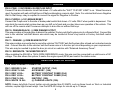
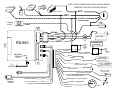
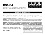
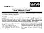
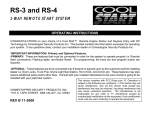
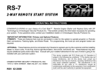
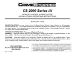
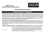
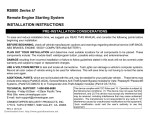
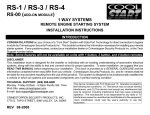
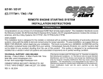
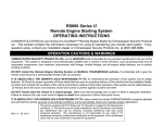
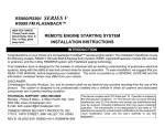
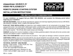
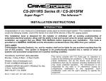
RS-850
Remote Engine Starting System
INSTALLATION INSTRUCTIONS
PRE-INSTALLATION CONSIDERATIONS
To ease and reduce installation time, we suggest you READ THIS MANUAL and consider the following points before
beginning your installation:
BEFORE BEGINNING, check all vehicle manufacturer cautions and warnings regarding electrical service (AIR BAGS,
ABS BRAKES, ENGINE / BODY COMPUTER AND BATTERY).
PLAN OUT YOUR INSTALLATION and determine most suitable locations for all components to be placed. These
components include: The module itself, valet/program button, possible extra relays, and antenna/receiver.
DAMAGE resulting from incorrect installation or failure to follow guidelines stated in this book will not be covered under
warranty and subject to repair or replacement charges.
USE A VOLT/OHM METER to test and locate all connections. Test Lights can damage a vehicle’s computer systems.
ADDITIONAL PARTS, which are not included with this unit, may be needed for your particular vehicle. . These items
may include extra relays (Part#CS-402A), and/or Anti-Theft System Bypass modules.
TECHNICAL SUPPORT: 1-800-998-6880
Monday - Friday 8:00am - 4:30pm Pacific Time
Web Site: www.crimestopper.com
E-mail: [email protected]
CRIMESTOPPER SECURITY PRODUCTS, INC.
1770 S. TAPO STREET, SIMI VALLEY, CA. 93063
REV A 8/2003
This device complies with FCC Rules part 15. Operation is subject to
the following two conditions: (1) This device may not cause harmful
interference, and (2) This device must accept any interference that
may be received, including interference that may cause undesired
operation. The manufacturer is not responsible for any radio or TV
interference caused by unauthorized modifications to this equipment.
Such modification could void the user’s authority to use the
equipment.
TABLE OF CONTENTS
Pre-Installation Considerations…………...……...………………………………………………………………Front Cover
Cautions & Warnings…….…………..….……..…..……………………………………………………………….…..……2
Wiring……..…………………………....……………………………………………………………………………….…….3-5
Wiring High-Current Connector…….………………...………………………………………………………………….....5-6
Power Door Lock Wiring…………...………………...…………………………………………………………………......7-8
Smart Tachless, Tach Reference & Tach Finder Modes…………………..…..………...…...…………………..….…9-10
Transmitter Programming……………………….…………………….……………..………...………………………....…11
2 Vehicle Operation.……………………………….……………………………………...…………………….……………11
Option Programming………..……………………….…………………………………...……………..………..……..…12-13
Troubleshooting “Before You Call” Section……………..…………………………..………………….……..….……….14
System Diagram…………………………………………………….……………………………………………….….……15
INSTALLATION CAUTIONS & WARNINGS
**FOR SAFETY REASONS, DO NOT INSTALL THE RS-850 in vehicles with MANUAL TRANSMISSIONS.** If
accidentally left in gear, a remote started vehicle could become a self-propelled threat to life and property.
WARNING: This system does NOT have engine over-rev protection. Make certain vehicle throttle linkage operates
properly and does not stick. A stuck throttle will cause severe engine damage
DO NOT extend the RS-850 Ignition harness length. Mount the module so that main harness reaches all ignition switch
wiring. Extending these wires could result in poor performance.
DO NOT route any wiring that may become entangled with brake, and gas pedals, steering column, or any other moving
parts in the vehicle.
DO NOT exceed the rated output current of any circuit on the Remote start module. Failure to observe this warning will
result in damage to the unit not covered under warranty.
DO NOT remote start the vehicle in a closed garage. Make sure that the garage door is open or there is adequate
ventilation. Failure to observe this rule could result in injury or death from poisonous Carbon Monoxide fumes.
2
WIRING
2 PIN PLUG-PROGRAM/OVERRIDE SWITCH:
This switch is used for programming features, transmitters, and valet mode.
2 PIN PLUG-(OPTIONAL) LED:
The LED is used as an indicator for Valet, Programming, and for use as security deterrent with the optional ANTIGRIND/STARTER DISABLE feature installed. Mount in a visible location on the dash or in the console if desired.
PIN 1 & 2: YELLOW / YELLOW/WHITE: (-) IGN / (-) ACC OUTPUTS (FOR ADDING RELAYS)
Use these wires when the vehicle requires a second IGNITION or ACCESSORY circuit to be activated. This occurs on
Toyota, late GM, and other models of vehicles. This wire is also used to activate ANTI-THEFT or TRANSPONDER
Bypass Modules. Connect to the “ground when running” input of the bypass module. (See Diagram Below.)
ANTI-THEFT/
TRANSPONDER
MODULE
OR
YELLOW or
YELLOW/WHITE
OR
85
86
30
87
Diode isolate
if using both!
2nd IGN/ACC
(If needed)
+12V CONSTANT
IGN SW.
PIN 3: BLACK: MAIN SYSTEM GROUND
Connect to chassis metal of the vehicle. An existing bolt or screw MAY provide an adequate ground, or drill a small
hole, scrape away paint and attach using a sheet metal screw & star washer. This wire MUST be connected to a good
ground or undesirable and inconsistent operation will occur.
3
WIRING
PIN 4: YELLOW/BLACK: (-) ANTI-GRIND/STARTER KILL OUTPUT (OPTIONAL)
Use this wire for the negative side of the Anti-Grind/Starter Disable relay. It can also be used as a sensor disable circuit
for a host alarm. This output activates whenever a remote start is requested, and when the vehicle is remotely locked
with the transmitter. (See diagram below)
TO
MOTOR
IGN 1
IGN 2
ACC
START
CUT
BROWN
85
YELLOW/BLACK
86
MAKE CERTAIN TO CONNECT "BROWN" START OUTPUT WIRE TO
MOTOR SIDE OF ANTI-GRIND/START DISABLE RELAY.
PIN 5: EMPTY (NOT USED)
PIN 6: GREEN: INSTANT START ACTIVATION BY NEGATIVE (-) TRIGGER INPUT (OPTIONAL ACCESSORY)
This wire allows the Auxiliary Channel Output of a separate (host) Alarm or Keyless Entry System to activate a Remote
Start. This wire can be used for the optional CS-400 Cool Start Timer/Temperature accessory. A 1 second (-) Negative
pulse on the Green wire will start/stop a remote start.
PIN 7: GRAY: (-) HOOD PIN SWITCH
Connect the Gray wire to a grounding hood switch. (Ground when open). If an existing switch is not available, then one
must be installed. When this wire is grounded, the remote start is inhibited. If hood is opened on a remote started
engine, the unit will immediately shut the motor off.
4
WIRING
PIN 8: PINK: (+12V) DIESEL GLOW PLUG INPUT
Connect Pink wire to indicator circuit that shows +12 volts while the “WAIT TO START LAMP” is on. When this wire is
used, the system will wait until light turns off before attempting a remote start. Note: For vehicles that have a Negative
Wait to Start lamp, relay is required to convert the signal for Negative to Positive.
PIN 9: PURPLE: (+12V) BRAKE RESET
Connect the Purple wire to the side of brake pedal switch that shows +12 volts ONLY when pedal is depressed. This
wire shuts the remote start system down as you shift out of park and your key takes over operation of the vehicle. This
will turn off the remote start if someone attempts to drive the car without the keys.
PIN 10: ORANGE/BLACK: (-) OEM DISARM OUTPUT
This wire provides a Ground pulse to disarm the vehicles' Factory anti-theft system prior to a Remote Start. Connect this
wire to the vehicles' anti-theft disarm wire which may be located at Driver's key switch or Factory Anti-theft control
module.
PIN 11: ORANGE: (-) OEM REARM OUTPUT
This wire provides a ground pulse to rearm the vehicles' FACTORY anti-theft system after a timed-out or aborted remote
start. Connect this wire to the vehicles' anti-theft rearm wire or to the door pin circuit depending on your requirements.
This wire may be needed to pulse the door pin circuit on vehicles with “Retained Accessory Power”.
PIN 12: RED/WHITE: TACHOMETER INPUT
When installing the RS-850 in TACH (RPM) REFERENCE mode, this wire must be connected to a valid source of AC
voltage. This wire allows the system to sense the engine speed (RPM) and control the starter motor.
IGNITION SWITCH WIRING
6 PIN HIGH-CURRENT CONNECTOR:
PIN 1: BROWN 14 GA.:
PIN 2: GRAY 14 GA.:
PIN 3: RED 14 GA.:
PIN 4: RED 14 GA.:
PIN 5: PINK 14 GA.:
PIN 6: WHITE 18 GA.:
STARTER OUTPUT (30A)
ACCESSORY (30A)
BATTERY CONSTANT FUSED (30A)
BATTERY CONSTANT FUSED (30A)
IGNITION 1 (30A)
(+) PARKING LIGHTS (10A)
NOTE: Heavy duty/High Current Ignition circuits greater than 30 AMPS, such as those found on Work or Industrial
vehicles, require high-current relays. Use Part #CS-403 relays for circuits up to 70 amps.
5
IGNITION SWITCH WIRING
Diagram Not to Scale.
For illustration purposes only.
Your vehicle may differ.
PARKING
LIGHTS
RED
WHITE
FUSE
30A
RED
+10A MAX.
FUSE
30A
+
FUEL
PUMP
+
ENGINE
ECU
PINK
GRAY
BROWN
BATTERY
STARTER
-
COIL
IGN 1
Heat/AC
ACC
IGN. Switch
6
POWER DOOR LOCK WIRING
PIN 1: BLUE: (-) Negative pulse for UNLOCK
PIN 2: RED: +12V When using external relays (TERM 86)
PIN 3: GREEN: (-) Negative pulse for LOCK
Crimestopper Door Lock Accessories:
CS-6600DLM: Dual-relay plug-in module for Reverse
Polarity, Positive, or Aftermarket Motors.
CS-6500DLI: Plug-in pulse inverter that converts the
Negative outputs of the system to Positive type for Positive
Door Lock systems.
CS-610S1: Aftermarket door lock actuator (motor).
DETERMINING DOOR LOCK TYPE: We recommend
determining the type of locking system the vehicle has before
connecting any wires. Incorrect connection may result in
damage to the alarm and/or vehicle locking system. Door lock
information is provided as a guide. Your vehicle may differ.
Negative Trigger (-): Many Imports; Late model Ford & General Motors
Negative trigger door lock systems send a Negative (Ground) pulse to existing factory relays to lock and unlock the
vehicle doors.
Positive Trigger (+): Many General Motors; Chrysler / Dodge / Plymouth
Positive trigger door lock systems send a Positive (+12V) pulse to existing factory relays to lock and unlock the
vehicle doors.
Reverse Polarity: Many Ford/Lincoln/Mercury/Dodge/Chrysler/Plymouth and early 90’s GM Trucks
Reverse Polarity systems use no relays, but instead the door lock/unlock motors are controlled directly from the lock
and unlock switches in the door. The lock and unlock wires rest at Negative Ground when not in use. When the
lock or unlock button is pressed, one of the circuits is “Lifted” and replaced with +12V causing a lock or unlock to
occur.
Single Wire (Dual Voltage): Late model Chrysler/Dodge/Plymouth Vehicles, some 2000-UP GM
Dual Voltage systems have lock/unlock switches that send varying levels of Positive voltage OR Negative ground
current to the SAME wire for both lock and unlock. When the vehicle’s Body Computer Module (BCM) or door lock
module senses different voltages on this wire, the system will either lock or unlock. Single wire door lock systems
require relays and resistors.
Databus Systems 2003 GM Trucks & SUV’s, ‘99-04 Jeep Grand Cherokee
Databus systems send low current “Data messages” to the door lock controllers in order to lock and unlock the vehicle.
To install aftermarket systems in these vehicles, an interface module is required that converts the regular lock/unlock
pulses into “Data messages” to allow locking & unlocking. Interface modules are sold separately.
7
BASIC DOOR LOCK DIAGRAMS
NEGATIVE TRIGGER DOORLOCK WIRING
POSITIVE TRIGGER DOORLOCK WIRING
GREEN
GREEN
RED
RED
BLUE
BLUE
FUSED
+12V
+
85
86
87
87A 30
FACTORY
POWER
LOCKING
RELAYS
L
UL
BLUE
85
86
87
87A 30
85
L
UL
FACTORY
POWER
LOCKING
RELAYS
AFTERMARKET MOTOR/DOOR LOCK WIRING
GREEN
FUSED
+12V
+
RED
BLUE
85
86
86
87
87A 30
87
87A 30
MASTER
SWITCH
+
87
87A 30
UL
FUSED
+12V
+
RED
86
L
REVERSE POLARITY DOOR LOCK WIRING
GREEN
85
CUT
CUT
8
85
86
87
87A 30
“SMART TACHLESS” MODE
Your CoolStart system includes a unique voltage monitor called “Smart Tachless” mode. This mode allows this unit to
efficiently start an engine without the use of a tach signal wire. These modules actively monitor the voltage level of the
vehicle to control the starter motor each time a remote start is requested.
IMPORTANT NOTES:
(1) SETUP may be required for Smart Tachless Mode. If your vehicle has not been at rest for a period of time (Hot
engine), then you must drain the surface charge from the battery. Unplug main power harness from unit, turn
HEADLIGHTS ON for 4 minutes to drain off excess surface charge on vehicle’s battery then reconnect.
(2) On the rare occasion that “Smart Tachless” mode does not operate satisfactorily, change the voltage reference level
as described below, or use “Tach Reference” mode.
“SMART TACHLESS” ADJUSTMENT:
In the event “Smart Tachless” over-cranks or under-cranks your starter, the settings can be changed. The purpose of
adjusting the “Smart Tachless” Mode is to raise or lower the voltage reference threshold from the 90% default point.
Raising or lowering this 90% point should increase or decrease your cranking time respectively. The adjustment range
is from 80% to 100% in one percent increments. The Default is 90%. Follow steps below to adjust the reference level.
1.
2.
3.
4.
Open hood (or ground Gray wire if no hood pin is installed)
Turn the key to the ON position
Press program button 5 times, after a few seconds the unit will flash the lights 5 times.
Carefully press the program button 6 times to get to option level 6. You must get a light flash after each press. If the
lights didn’t flash, then the unit did not register your button press. Only count the light flash.
5. Press the Lock Button #1 on the remote to decrease by 1% (lights will flash 1X for each press); Press the Start Button
#2 to increase by 1% (lights will flash 2X for each press). The unit will stop providing light flashes when you reach the
bottom (80%) or the top (100%) of the adjustment range.
6. Turn Ignition OFF, Close hood (or un-ground the Gray wire) and check operation.
9
TACH (RPM) REFERENCE MODE / TACH FINDER MODE / TACH PROGRAMMING
Tach Reference Mode provides reliable remote starting performance though engine speed sensing. When using Tach
Reference Mode, the Red/White wire is used for Tach signal [Engine RPM] input. Most modern engines include various
points where the Engine Speed [Tach] or A/C signal may be obtained. Tach Signal examples: Negative (-) side of
ignition coil, at the Distributor or Ignition Control Module, Coil Pack, Engine Computer, or Crankshaft Sensor.
Sometimes Fuel injection solenoids, and Alternator stator pins can be used. These Tach Signal locations mentioned are
provided as a guide, your vehicle may differ. Some locations will NOT be a good location for Tach source due to RF
noise or Data.
TACH FINDER MODE:
This system includes a Tach Finder mode to assist in locating a valid or viable tach source for your installation. Follow
the Tach Finder steps to locate and /or verify a tach signal. If you are already aware of a good Tach source for your
vehicle, then you may go directly to TACH PROGRAMMING steps. Note that on vehicles with daytime running lights, it
may be difficult to see any flashing parking lights. In this case your only notification will be the slight “ticking” sound
coming out of the module from the on-board flashing light relay.
TACH FINDER:
1. Open hood (or ground Gray hood pin wire if no hood pin is installed)
2. Start Engine with the key.
3. Press the Program button for 2 seconds
4. Lights will begin flashing if the Red/White wire is connected to a valid tach source. If not try a different wire until one
is located.
5. Once Tach is located then turn off engine and close hood. (un-ground Gray wire).
6. See Tach programming below.
TACH PROGRAMMING:
1. Open hood (or ground Gray hood pin wire if no safety hood pin is installed.)
2. Red/White wire should be connected to a valid Tach source.
3. Start engine with key.
4. Press program button 5 times, then wait for 5 light flashes.
5. Push program button again 4 times. (You must get a light flash after button is pressed.) This unit is now at
option #4-Tach Learning.
6. Press the #1 Lock/Unlock Button on remote transmitter. The unit will read the Tach source and flash the lights
once for program confirmation.
7. If lights do not flash once for confirmation, then try another tach source.
10
TRANSMITTER PROGRAMMING
Note: All transmitter codes must be learned at time of programming!! The RS800 allows storage of up to 4
different transmitter codes.
1.
2.
3.
4.
Open Hood. (Ground Gray wire.)
Turn key to the ON position.
Press Programming button 4 times, then after a few seconds the unit will flash the parking lights 4 times.
Press button #1 of the transmitter to be coded. You should get 2 light flashes indication the unit is waiting for a 2nd
code, then press button #1 of a second transmitter, the unit will flash 3 times indicating its waiting for the 3rd code and
lights will flash 4 times for 4th code. If all 4 codes are learned, the unit will automatically exit code learning mode,
otherwise turn key OFF and close hood.
2-VEHICLE OPERATION
The RS-850 system can be used for 2 car operation. A single RS-850 remote can
control two independent vehicles with RS-850 systems installed.
CAR I / CAR II OPERATION
SETUP:
1. Using the switch on the side of the remote set your controller to Car II.
2. At Car II: Simply follow the transmitter programming steps listed in the
section above. Learn YOUR remote, along with Car 2’s existing remotes.
CAR I
START
Slide
CAR II
11
OPTION PROGRAMMING
IMPROVED: Now you can program multiple options in one session if you start with the lowest option and continue on to
higher options [if needed] without repeating the steps #1-3. For example, you can change Option #2 to “ON” by pressing
the lock button, then you can continue pressing the program button to get to a high number option and change it as well
without having to repeat Steps 1-5. You can only go from low to higher options numbers in one session.
Option Programming:
1. Open hood (Ground the Gray wire if no hood pin is installed).
2. Turn Key to the ON position
3. Press program button 5 times, after a few seconds the unit will flash the lights 5 times.
4. Push the valet/program button [again] the number of times that corresponds to the option number desired. You
should get a light flash after each button press. If the system did not flash the lights, then it did not register your
press.
5. When you reach the desired programming level, Press button #1(Lock) or #2 (Start) to change the option. See
the chart below for option values and descriptions.
6. Turn Ignition OFF, Close hood and check for changed features.
OPTIONS CHART
* = DEFAULT
Option
#
1
2
NOT USED
Door Lock Pulse Time
3
4
Double Unlock Pulse
Engine Monitoring
5
Remote Start Engine Run
Time
Smart Tachless Voltage
Adjust (80-100%) Only when
Option #4 is set to Tachless
Option reset
6
7
Option Description
Option Values
0.75 Sec. (Standard) OR
3.0 Sec. (European Vacuum)
ON or OFF
Tach (Engine RPM) or
Tachless Mode
Button #1 = 48 Min.
Button #2 = 24 Min.
Button #1 = Decrease by 1%
Button #2 = Increase by 1%
Button #2
12
Button #1
LOCK
Button #
START
3 Sec.
0.75 Sec.*
ON
Learn Tach
OFF*
Tachless*
36 Min.
24 Min*.
-1%
+1%
Reset to
Default
OPTION PROGRAMMING
OPTION DESCRIPTIONS:
1. NOT USED: No Option
2. Door Lock Pulse Time:
Controls the amount of time for lock/unlock pulse. The standard setting is 0.75 for most vehicles. A 3 sec. setting is
required for 1980’s/90’s European Vacuum or Pneumatic door lock systems.
3. Double Unlock Pulse:
The unit will send 2 unlock pulses when the #2 Unlock button is pressed. This feature may be required for interfacing
this alarm with an existing Factory Keyless Entry or Alarm system in a vehicle. These systems are found on some
Nissan, VW, Toyota, and Lexus vehicles.
4. Engine Monitoring:
This option sets how the unit monitors your engine. You can program either for Tach mode in which the unit uses a
Tach signal (RPM) or for Tachless mode that monitors voltage level. See pages 9-10 for more information and
additional steps for actual Tach learning and Tach finder modes.
5. Remote Start Run Time:
This option controls the engine run time for remote start. You can select either 24 or 36 minutes.
6. Smart Tachless Voltage Adjustment:
This option controls the voltage reference point when using Smart Tachless mode. Either tapping the brake or pressing
the Start button on the remote raises or lowers the reference level in 1% increments from 80%-%100. The default
voltage setting is 90%, which works well for most vehicles. See page 9 for additional Smart Tachless mode information.
7. Option Reset:
This option allows you to restore all programmable options to factory default values. Go to the 7th option and press
the Start Button on the remote. The unit will flash the lights 2 times and all values will be reset to Default.
13
REMOTE START TROUBLESHOOTING “Before You Call Section”
UNIT FLASHES LIGHTS ONCE AND WILL NOT ATTEMPT A START:
The unit is in Valet mode. Turn IGN ON, press and hold valet/programming button for about 4 seconds until LED goes
out. The unit is now out of valet mode and should perform a remote start.
UNIT FLASHES LIGHTS TWICE AND WILL NOT ATTEMPT A START:
The unit reads a fault at the Brake (Purple wire is active) or the Hood is OPEN (Gray wire grounded). This is a safety
feature of the unit. Check installation for faults and make sure hood is closed and latched.
UNIT CRANKS VEHICLE BUT ENGINE NEVER STARTS:
1. In some vehicles, there may be a Factory anti-theft system that will not allow the engine to run without the key in the
ignition. These systems may include Factory Security Modules, GM Passkey®/Passlock®, and RF Transponder
systems (Ford P.A.T.S.®). Many late 1990’s and 2000-UP vehicles include some type of Anti-Theft system which
may require a bypass module. Bypass modules are sold separately.
2. The vehicle may have more than one Ignition/or Accessory circuit that requires power for the vehicle to start. This is
common on some GM/Toyota vehicles.
VEHICLE STARTS BUT CHECK ENGINE LIGHT COMES ON OR ENGINE RUNS BADLY:
1. Many 1995-UP General Motors cars/trucks require a secondary ignition circuit for the Transmission computer and
other on board systems. If the vehicle is started without this wire energized, there may be a “Check Engine” or
“Service Engine” light on the dash. This may cause damage if the vehicle is driven in this condition. Be sure to
check for and additional WHITE (or sometimes GREEN) Ignition wire on GM cars and trucks.
2. Some Vehicles (Commonly Nissan) require 2 Start (Cranking) circuits for the vehicle to run properly. If this is the
case, then an additional relay must be installed (triggered off of the BROWN start output wire). Connected to the
Extra start relay output to the extra start wire in the vehicle. Secondary starter wire may be a smaller wire than the
primary starter wire.
NO RESPONSE FROM REMOTE TRANSMITTER:
1. Check for proper power/ground wiring connections.
2. Check Antenna Module connection. The antenna module included with this system must be plugged in to allow the
unit to send/receive signals.
3. The Remote Transmitters may need to be reprogrammed to operate the system. See Transmitter programming.
4. Remote Transmitters may be damaged or need new batteries.
14
ENGINE
ECU
TRANSMISSION
ECU
+
NOTE: USE EXTERNAL RELAYS FOR HIGH-CURRENT
(GREATER THAN 30A) IGNITION CIRCUITS.
FUEL
PUMP
-
ACC
H/V/AC CONTROL
COIL
IGN 1
2nd IGN 1
(If necessary)
PARKING
LIGHTS
12A MAX.
STARTER
BROWN
GRAY
RED
RED
PINK
WHITE
RS-850
+
30A
FUSE
BATTERY
FUSE
30A
YELLOW
(-)IGN OUT
85 86
TO SECOND ACC
(If necessary)
+
30 87
FUSED
12V
YELLOW/WHITE
(-) IGN2 / ACC OUT
ANTENNA/
RECEIVER
PLUG
30 87
+
85 86
FUSED
12V
BLACK
GROUND
(-) ANTI-GRIND/
STARTER DISABLE
RELAY OUTPUT
YELLOW/BLACK
GREEN
(-) START ACTIVATION
TO
ANTENNA
-
RS801 - TO KEYLESS
ENTRY SYSTEM OR
ALARM AUX. OUTPUT
GRAY
(-) HOOD SWITCH
DIESEL (+12V) WAIT
TO START LAMP
PINK
(+12V) GLOW PLUG INPUT
LED
PURPLE
(+12V) BRAKE PEDAL RESET
PROGRAM/
OVERRIDE
SWITCH
(-) UNLOCK OUTPUT
BLUE
+12 V FOR RELAYS
RED
(-) LOCK OUTPUT
GREEN
WAIT
ORANGE/BLACK: (-) OEM DISARM
ORANGE: (-) OEM REARM
RED/WHITE
TACH INPUT
2
1
3
4 5 6
7
8
0
TACH
www.crimestopper.com
[email protected]
Phone (800) 998-6880
FAX (805) 581-9500
© 2003 Crimestopper Security Products
ONLINE TECHNICAL SUPPORT
www.crimestopper.com/techweb03.html