1
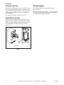
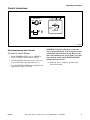
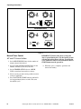
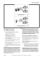
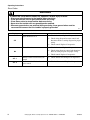
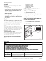
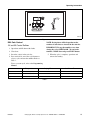
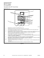
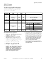
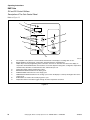
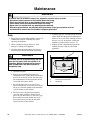
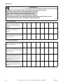
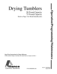
Operation/Programming/Maintenance
Drying Tumblers
50 Pound Capacity
75 Pound Capacity
Refer to Page 3 for Model Identification
Keep These Instructions for Future Reference.
(If this machine changes ownership, this manual must accompany machine.)
www.comlaundry.com
Part No. 70400301R5
January 2009
Installation must conform with local codes or in the absence of local codes with:
In the U.S.A., installation must conform to the latest edition of the American National Standard Z223.1/
NFPA 54 “National Fuel Gas Code” and Standard ANSI/NFPA 70 “National Electric Code.”
In Canada, installation must comply with Standards CAN/CSA-B149.1 or Natural Gas and Propane Code
CSA C22.1, latest edition, Canadian Electric Code, Part I.
In Australia, installation must comply with the Australian Gas Association Installation Code for Gas
Burning Appliances and Equipment.
WARNING
MISE EN GARDE
FOR YOUR SAFETY, the information in this
manual must be followed to minimize the
risk of fire or explosion or to prevent
property damage, personal injury or death.
W033
• Do not store or use gasoline or other
flammable vapors and liquids in the
vicinity of this or any other appliance.
• WHAT TO DO IF YOU SMELL GAS:
– Do not try to light any appliance.
– Do not touch any electrical switch; do
not use any phone in your building.
– Clear the room, building or area of all
occupants.
– Immediately call your gas supplier from
a neighbor’s phone. Follow the gas
supplier’s instructions.
– If you cannot reach your gas supplier,
call the fire department.
• Installation and service must be
performed by a qualified installer, service
agency or the gas supplier.
W052
FOR YOUR SAFETY
Do not store or use gasoline or other
flammable vapors and liquids in the
vicinity of this or any other appliance.
W053
POUR VOTRE SÉCURITÉ, les informations
de ce guide doivent être respectées afin de
réduire les risques d’incendie, d’explosion
ou d’éviter les dommages matériels,
personnels ou blessures mortelles.
W033R3QU
• Ne pas entreposer ou utiliser d’essence
ou toutes autres vapeurs et liquides
inflammables à proximité de cette
machine ou de tout autre appareil.
• QUE FAIRE EN CAS D’ODEUR DE GAZ :
– Ne pas mettre d’appareil en marche.
– Ne pas toucher aux interrupteurs
électriques ; ne pas utiliser le
téléphone des lieux.
– Évacuer la pièce, le bâtiment ou la zone
de tous les occupants.
– Appeler immédiatement le fournisseur
de gaz de la maison d’un voisin.
Respecter les instructions
communiquées par le fournisseur.
– Si vous ne pouvez pas joindre le
fournisseur de gaz, appeler le service
d’incendie.
• L’installation et l’entretien doivent être
effectués par un installateur, service
d’entretien qualifiés ou par le fournisseur
de gaz.
W052R5QU
POUR VOTRE SÉCURITÉ
Ne pas entreposer ou utiliser d’essence ou
toutes autres vapeurs et liquides
inflammables à proximité de cette unité ou
de tout autre appareil.
W053R2QU
IMPORTANT: Information must be obtained from a local gas supplier on instructions to be followed if the
user smells gas. These instructions must be posted in a prominent location. Step-by-step instructions of the
above safety information must be posted in a prominent location near the tumbler for customer use.
70400301
© Copyright, Alliance Laundry Systems LLC – DO NOT COPY or TRANSMIT
1
Table of
Contents
Introduction.........................................................................................
Model Identification .............................................................................
Customer Service..................................................................................
Serial Plate Location.............................................................................
Wiring Diagram ....................................................................................
3
3
4
4
4
Safety Information..............................................................................
Explanation of Safety Messages...........................................................
Important Safety Instructions ...............................................................
5
5
6
Operating Instructions .......................................................................
Emergency Stop Button on CE Models................................................
Operating Instructions ..........................................................................
Control Instructions ..............................................................................
Electromechanical Coin Control......................................................
Manual Timer Control .....................................................................
Dual Digital Timer Control..............................................................
Single Drop Control .........................................................................
DX4 Coin Control............................................................................
DX4 OPL Control ............................................................................
Diagnostic Microprocessor Control .................................................
DMP OPL Models ...........................................................................
DMP Coin ........................................................................................
Ignition Control Operation ...................................................................
8
8
8
9
9
10
11
13
15
16
17
18
20
24
Maintenance ........................................................................................
Daily .....................................................................................................
Monthly.................................................................................................
Quarterly ...............................................................................................
Bi-Annually ..........................................................................................
Annually ...............................................................................................
26
26
27
27
27
27
Before You Call for Service ............................................................... 31
Customer Service.................................................................................. 31
© Copyright 2009, Alliance Laundry Systems LLC
All rights reserved. No part of the contents of this book may be reproduced or transmitted in any form or by any
means without the expressed written consent of the publisher.
2
© Copyright, Alliance Laundry Systems LLC – DO NOT COPY or TRANSMIT
70400301
Introduction
Model Identification
Information in this manual is applicable to these models:
Gas
50 Pound
75 Pound
CHD50G2-CA050L
CHD50G2-CA050N
CHD50G2-CT050L
CHD50G2-CT050N
CHD50G2-CU050L
CHD50G2-CU050N
DR55G2-BA050L
DR55G2-BA050N
DR55G2-BT050D
DR55G2-BT050L
DR55G2-BT050N
DR55G2-BU050L
DR55G2-BU050N
IPD50G2-IT050L
IPD50G2-IT050N
CHD75G2-CA075L
CHD75G2-CA075N
CHD75G2-CT075L
CHD75G2-CT075N
CHD75G2-CU075L
CHD75G2-CU075N
DR80G2-BA075L
DR80G2-BA075N
DR80G2-BT075D
DR80G2-BT075L
DR80G2-BT075N
DR80G2-BU075L
DR80G2-BU075N
IPD75G2-IT075L
IPD75G2-IT075N
Steam/Thermal Oil
Electric
CHD50S2-CT050S
CHD50S2-CU050S
CT050T
CU050T
DR55S2-BT050S
DR55S2-BT050T
DR55S2-BU050S
DR55S2-BU050T
IPD50S2-IT050S
IPD50S2-IT050T
CHD50E2-CT050E
CHD50E2-CU050E
DR55E2-BT050E
DR55E2-BU050E
IPD50E2-IT050E
CHD75S2-CT075S
CHD75S2-CU075S
CT075T
CU075T
DR80S2-BT075S
DR80S2-BT075T
DR80S2-BU075S
DR80S2-BU075T
IPD75S2-IT075S
IPD75S2-IT075T
CHD75E2-CT075E
CHD75E2-CU075E
DR80E2-BT075E
DR80E2-BU075E
IPD75E2-IT075E
Includes models with control suffixes:
3O – DX4 OPL
3V – DX4 vended
3X – DX4 prep for coin
CD – rotary coin drop
CX – prep for coin
DO – DMP OPL
70400301
DV – DMP vended
DX – DMP prep for coin
MT – manual timer
QT – dual digital timer
R3 – reversing DX4 OPL
RD – reversing DMP OPL
RQ – reversing dual digital timer
RT – reversing manual timer
SD – single drop
SX – single drop, prep for coin
© Copyright, Alliance Laundry Systems LLC – DO NOT COPY or TRANSMIT
3
Introduction
Customer Service
Wiring Diagram
If literature or replacement parts are required, contact
the source from which the machine was purchased or
contact Alliance Laundry Systems at (920) 748-3950
for the name and address of the nearest authorized
parts distributor.
The wiring diagram is located in the junction or
contactor box.
Models starting Serial No. 0309___ or later will have
the wiring diagram part number in the lower portion of
the electrical data on the serial plate.
For technical assistance, call (920) 748-3121.
Serial Plate Location
When calling or writing for information about your
product, be sure to mention model and serial numbers.
Model and serial numbers are found on serial plate on
rear of machine, and inside door hinge. Refer to
Figure 1.
0
5
N
COOL
DOW
ERAT
URE
LOW
15
10
10
0
TEMP
HEAT
60
20
50
HIGH
30
40
PUSH
TO T
STAR
1
TMB803N
TMB803N
1
Serial Plate
Figure 1
4
© Copyright, Alliance Laundry Systems LLC – DO NOT COPY or TRANSMIT
70400301
Safety Information
Explanation of Safety Messages
Precautionary statements (“DANGER,” “WARNING,”
and “CAUTION”), followed by specific instructions,
are found in this manual and on machine decals. These
precautions are intended for the personal safety of the
operator, user, servicer, and those maintaining the
machine.
DANGER
Indicates an imminently hazardous
situation that, if not avoided, will cause
severe personal injury or death.
WARNING
Indicates a hazardous situation that, if not
avoided, could cause severe personal
injury or death.
CAUTION
Indicates a hazardous situation that, if not
avoided, may cause minor or moderate
personal injury or property damage.
Additional precautionary statements (“IMPORTANT”
and “NOTE”) are followed by specific instructions.
IMPORTANT: The word “IMPORTANT” is used
to inform the reader of specific procedures where
minor machine damage will occur if the procedure
is not followed.
IMPORTANT: Warranty is void unless tumbler
is installed according to instructions in the
Installation Manual. Compliance with minimum
specifications and requirements detailed herein,
and with applicable local gas fitting regulations,
municipal building codes, water supply regulations,
electrical wiring regulations, and any other
relevant statutory regulations. Because of varied
requirements, applicable local codes should be
thoroughly understood and all pre-installation
work arranged for accordingly.
WARNING
Failure to install, maintain, and/or operate
this machine according to manufacturer’s
instructions may result in conditions which
can produce serious injury, death and/or
property damage.
W051R1
NOTE: The WARNING and IMPORTANT
instructions appearing in this manual are not
meant to cover all possible conditions and
situations that may occur. It must be understood
that common sense, caution and carefulness are
factors which CANNOT be built into this tumbler.
These factors MUST BE supplied by the person(s)
installing, maintaining or operating the tumbler.
Always contact your dealer, distributor, service agent
or the manufacturer on any problems or conditions you
do not understand.
NOTE: The word “NOTE” is used to communicate
installation, operation, maintenance or servicing
information that is important but not hazard
related.
70400301
© Copyright, Alliance Laundry Systems LLC – DO NOT COPY or TRANSMIT
5
Safety Information
Important Safety Instructions
14. The interior of the tumbler and the exhaust duct
should be cleaned periodically by qualified
service personnel.
Save These Instructions
WARNING
Hazardous Voltage. Can cause shock, burn
or cause death. Allow machine power to
remain off for two minutes prior to working
in and around AC inverter drive.
W359
1. Read all instructions before using the tumbler.
2. Refer to the GROUNDING INSTRUCTIONS
for the proper grounding of the tumbler.
3. Do not dry articles that have been previously
cleaned in, washed in, soaked in, or spotted with
gasoline, dry cleaning solvents, other flammable
or explosive substances as they give off vapors
that could ignite or explode.
4. Do not allow children on or in the tumbler. This
appliance is not intended for use by young
children or infirm persons without supervision.
Young children should be supervised to ensure
that they do not play with the appliance.
15. If not installed, operated and maintained in
accordance with the manufacturer’s instructions
or if there is damage to or mishandling of this
product’s components, use of this product could
expose you to substances in the fuel or from fuel
combustion which can cause death or serious
illness and which are known to the State of
California to cause cancer, birth defects or other
reproductive harm.
16. Tumbler will not operate with the loading door
open. DO NOT bypass the door safety switch to
permit the tumbler to operate with the door open.
The tumbler will stop tumbling when the door is
opened. Do not use the tumbler if it does not stop
tumbling when the door is opened or starts
tumbling without pressing or turning the START
mechanism. Remove the tumbler from use and
call for service.
17. Tumbler will not operate with lint panel open.
DO NOT bypass lint panel safety switch to
permit the tumbler to operate with the lint panel
open.
5. Before the tumbler is removed from service or
discarded, remove the door to the drying
compartment and the door to the lint
compartment.
18. Do not put articles soiled with vegetable or cooking
oil in the tumbler, as these oils may not be
removed during washing. Due to the remaining
oil, the fabric may catch on fire by itself.
6. Do not reach into the tumbler if the cylinder is
revolving.
19. To reduce the risk of fire, DO NOT put clothes
which have traces of any flammable substances
such as machine oil, flammable chemicals,
thinner, etc. or anything containing wax or
chemicals such as in mops and cleaning cloths, or
anything dry-cleaned at home with dry-cleaning
solvent in the tumbler.
7. Do not install or store the tumbler where it will
be exposed to water and/or weather.
8. Do not tamper with the controls.
9. Do not repair or replace any part of the tumbler,
or attempt any servicing unless specifically
recommended in the user-maintenance
instructions or in published user-repair
instructions that you understand and have the
skills to carry out.
10. Do not use fabric softeners or products to
eliminate static unless recommended by the
manufacturer of the fabric softener or product.
11. To reduce the risk of fire, DO NOT DRY plastics
or articles containing foam rubber or similarly
textured rubberlike materials.
20. Use the tumbler only for its intended purpose,
drying fabrics.
21. ALWAYS disconnect and lockout the electrical
power to the tumbler before servicing. Disconnect
power by shutting off appropriate breaker or fuse.
22. Install this tumbler according to the
INSTALLATION INSTRUCTIONS. All
connections for electrical power, grounding, and
gas supply must comply with local codes and be
made by licensed personnel when required.
12. Always clean the lint filter daily.
13. Keep area around the exhaust opening and
adjacent surrounding area free from the
accumulation of lint, dust and dirt.
6
© Copyright, Alliance Laundry Systems LLC – DO NOT COPY or TRANSMIT
70400301
Safety Information
23. Remove laundry immediately after tumbler stops.
29. DO NOT bypass any safety devices.
24. Always read and follow manufacturer’s
instructions on packages of laundry and cleaning
aids. Heed all warnings or precautions. To reduce
the risk of poisoning or chemical burns, keep
them out of reach of children at all times
(preferably in a locked cabinet).
30. Solvent vapors from dry-cleaning machines
create acids when drawn through the heater of the
drying unit. These acids are corrosive to the
tumbler as well as to the laundry load being
dried. Be sure make-up air is free of solvent
vapors.
25. Do not tumble fiberglass curtains and draperies
unless the label says it can be done. If they are
dried, wipe out the cylinder with a damp cloth to
remove particles of fiberglass.
31. Failure to install, maintain, and/or operate this
machine according to the manufacturer’s
instructions may result in conditions which can
produce bodily injury and/or property damage.
26. Always follow the fabric care instructions
supplied by the garment manufacturer.
27. Never operate the tumbler with any guards and/or
panels removed.
28. DO NOT operate the tumbler if it is smoking,
grinding, has missing or broken parts.
70400301
WARNING
To reduce the risk of serious injury, install
lockable door(s) to prevent public access
to rear of tumblers.
© Copyright, Alliance Laundry Systems LLC – DO NOT COPY or TRANSMIT
W055
7
Operating Instructions
WARNING
To reduce the risk of fire:
• DO NOT DRY articles containing foam rubber or similarly textured rubberlike materials.
• DO NOT DRY plastics, anything containing wax or chemicals such as mops and cleaning
cloths, or anything dry-cleaned at home with a dry-cleaning solvent.
• DO NOT TUMBLE fiberglass curtains and draperies unless the label says it can be done. If
they are dried, wipe out the cylinder with a damp cloth to remove particles of fiberglass.
W076
To reduce the risk of serious injury, allow cylinder to stop before cleaning lint screen.
W412
Emergency Stop Button on CE
Models
Operating Instructions
All CE approved OPL tumblers are factory equipped
with an emergency stop button located on the front
panel. Refer to Figure 2.
Remove any accumulated lint from the lint screen and
compartment. Close panel tightly against tumbler
frame and lock panel securely, if applicable.
Step 1: Clean Lint Screen/Compartment
IMPORTANT: Clean lint screen and lint
compartment daily. Failure to clean the lint screen
daily will result in higher than normal
temperatures that may damage laundry.
1
Step 2: Load Laundry
Open loading door and load cylinder with laundry. DO
NOT OVERLOAD.
NOTE: Overloading causes slow drying and
wrinkling.
TMB1664N
1
Emergency Stop Button
Figure 2
To operate emergency stop button:
Close loading door. Tumbler will not operate with the
door open.
Step 3: Determine Control Type and
Temperature Setting
a. Press red emergency stop button to stop all
action.
Refer to the various controls, pages 9-23, follow
instructions for the appropriate control type.
b. To restart machine, pull red emergency stop
button out and press START pad or button.
The type of fabric being dried will determine the
temperature setting. Consult the fabric care label or
fabric manufacturer to determine proper temperature
setting.
NOTE: Activation of the emergency stop button
stops all machine control circuit functions, but
DOES NOT remove all electrical power from
machine.
IMPORTANT: Always follow the fabric care
instructions supplied by the garment manufacturer.
Step 4: Remove Laundry
When the cycle is complete, open door and remove the
laundry.
8
© Copyright, Alliance Laundry Systems LLC – DO NOT COPY or TRANSMIT
70400301
Operating Instructions
Control Instructions
1
HIGH
2
SELECT
TEMP
TEMPERATURE
3
INSERT
COIN
PUSH
START
LOW
INSERT QUARTER
TURN KNOB
QU
PUSH
TO
START
25
ARTE
RMAST
ER
TMB807N
TMB807N
Figure 3
Electromechanical Coin Control
CD and CX Control Suffixes
1. Set the TEMPERATURE selector at HIGH or
LOW, or anywhere between these settings.
2. Coin Drop Models: Insert the coin(s) in the coin
slot, turn the knob to the right and release it.
3. Press the PUSH TO START button and hold it for
approximately three (3) seconds.
70400301
IMPORTANT: If the loading door or lint panel
door is opened during the cycle, the heating system
will shut off and the motor will stop. However, the
timer will continue to run. To restart the cycle, both
doors must be closed and the PUSH TO START
button must be pressed in.
4. When the cycle is complete, open door and
remove the laundry.
© Copyright, Alliance Laundry Systems LLC – DO NOT COPY or TRANSMIT
9
Operating Instructions
REVERSING MODELS
0
TMB804N
0
60
10
15
50
20
40
5
HEAT
10
30
COOL
DOWN
TEMPERATURE
HIGH
PUSH
TO
START
NONREVERSING MODELS
LOW
TMB805N
TMB805N
Figure 4
Manual Timer Control
MT and RT Control Suffixes
1. Set the HEAT/DRYING timer for the number of
minutes (from 0-60) desired.
2. Set the COOL DOWN/COOLING timer for the
number of minutes (from 0-15) desired.
IMPORTANT: If the loading door or lint panel
door is opened during the cycle, the heating system
will shut off and the motor will stop. To restart the
cycle, both doors must be closed and the PUSH TO
START button must be pressed in.
6. When the cycle is complete, open door and
remove the laundry.
3. Set the TEMPERATURE selector at HIGH,
LOW or anywhere between these settings.
4. Select reversing or nonreversing cylinder rotation
setting, if applicable.
5. Press the PUSH TO START button in and hold it
in for approximately three seconds. This starts
the tumbler cycle.
10
© Copyright, Alliance Laundry Systems LLC – DO NOT COPY or TRANSMIT
70400301
Operating Instructions
REVERSING MODELS
TMB2136N
TMB2136N
NONREVERSING MODELS
TMB2133N
Figure 5
Dual Digital Timer Control
QT and RQ Control Suffixes
1. Select HIGH, MED, LOW or NO HEAT by
turning the temperature knob.
HIGH temperature 190°F (87°C)
MED temperature 170°F (77°C)
LOW temperature 120°F (49°C)
2. Set the HEAT TIME for the number of minutes
(from 0-60) desired.
3. Set the COOL DOWN TIME for the number of
minutes (from 0-15) desired.
4. Select reversing or nonreversing cylinder rotation
setting, if applicable.
5. Press and release START button to start tumbler.
Display will show minutes remaining before end
of cycle.
NOTE: One touch drying is available for repetitive
loads. If the START button is pressed while the
machine is in Idle Mode, when the display is dark,
the tumbler will repeat the last drying cycle. If the
cycle time is adjusted before the cycle is started, the
time displayed when the start button was pressed
will be used for future cycles.
70400301
IMPORTANT: To stop the tumbler at any time
during the cycle, OPEN DOOR. If the loading door
or lint panel door is opened during the cycle, the
heating system will shut off and the motor will stop.
To restart the cycle, both doors must be closed and
the START button must be pressed in.
If the load cools to 90°F before cool down time
expires, the control will flash “Lr” (load ready) in the
heat time display. If the door is not opened, the
tumbler completes the selected cool down time. If the
door is opened after reaching “Lr” temperature, the
cycle will be terminated.
NOTE: If display shows an error code, refer to
Error Codes section.
6. When the cycle is complete, open door and remove
the laundry. Anti-wrinkle feature will tumble the
load without heat for 30 seconds every 2 minutes
for 1 hour OR until the loading door is opened.
NOTE: This machine includes an anti-wrinkle
extended tumble feature. After the drying cycle is
complete, the cylinder will tumble without heat
every few minutes. The intermittent tumbling will
continue for one hour or until the door is opened.
© Copyright, Alliance Laundry Systems LLC – DO NOT COPY or TRANSMIT
11
Operating Instructions
Error Codes
WARNING
To reduce the risk of electric shock, fire, explosion, serious injury or death:
• Disconnect electric power to the tumbler before servicing.
• Close gas shut-off valve to gas tumbler before servicing.
• Close steam valve to steam tumbler before servicing.
• Never start the tumbler with any guards/panels removed.
• Whenever ground wires are removed during servicing, these ground wires must be
reconnected to ensure that the tumbler is properly grounded.
W002
Display
Definition
Open thermistor error
Corrective Action
●
Check thermistor. Replace if inoperative.
●
Check wiring diagram between control and
thermistor. Refer to wiring diagram for proper
wiring.
●
Check control. Replace if inoperative.
Check thermistor. Replace if inoperative.
OP
Shorted thermistor error
SH
12
●
●
Check wiring between control and thermistor.
Refer to wiring diagram for proper wiring.
●
AF - 1
Airflow switch closed when cycle
started
●
Check control. Replace if inoperative.
Check airflow switch. Replace if inoperative.
AF - 2
Airflow switch failed to close after
cycle started
●
Check airflow switch. Replace if inoperative.
© Copyright, Alliance Laundry Systems LLC – DO NOT COPY or TRANSMIT
70400301
Operating Instructions
TMB2123N
Figure 6
Single Drop Control
Preliminary Control Information
SD and SX Control Suffixes
Power-Up Mode
1. Select HIGH, MED, LOW or NO HEAT by
turning the temperature knob.
HIGH temperature 190°F (87°C)
MED temperature 160°F (71°C)
LOW temperature 130°F (54°C)
2. Insert the coin(s) in the coin slot.
3. Press START button to start tumbler.
IMPORTANT: To stop the tumbler at any time
during the cycle, OPEN DOOR. To restart the
tumbler, CLOSE door and press START button.
NOTE: If display shows an error code, refer to
Error Codes section.
4. When the cycle is complete, open door and
remove the laundry.
NOTE: This machine includes an extended tumble
feature. Starting 20 minutes after a cycle ends, the
cylinder will tumble for two minutes every hour
without heat, up to 18 hours or until door is
opened.
70400301
When power is applied to the tumbler the control will
enter Ready Mode, unless a cycle was in process prior
to a disruption of power. If a power disruption is less
than 5 seconds, with a cycle in process, the control will
enter Run Mode once power is restored and continue
the cycle. If a power disruption is more than 5 seconds,
with a cycle in process, the control will enter Start
Mode once power is restored.
If the dry time dipswitch settings have not changed
from the factory default, the IN USE LED will flash
two to five times, depending on model.
Ready Mode
In Ready Mode, the control waits for the vend to be
satisfied before entering Start Mode.
Start Mode
In Start Mode, the vend has been satisfied, but the
Start button has not been pressed. The IN USE LED
will be lit. The timer will not count down until the
Start button is pressed.
© Copyright, Alliance Laundry Systems LLC – DO NOT COPY or TRANSMIT
13
Operating Instructions
Run Mode
High/Normal: 4 flashes
Medium/PP: 3 flashes
Low/Delicate: 2 flashes
No Heat: 1 flash
In Run Mode, the control is running a cycle. The IN
USE LED is lit.
Door Open Mode
In Door Open Mode, the control turns off the heater
and motor when the door is opened during a run
cycle. The timer will continue to count down time
and the IN USE LED is lit.
End of Cycle Mode
In End of Cycle Mode, a cycle is complete and the
IN USE LED is off. The control remains in this
mode until the door is opened or additional vend has
been satisfied.
NOTE: To change dipswitch settings refer to
Installation Manual.
To Program a Short Test Cycle:
1. Unplug machine power cord.
2. Write down machine control dip switch settings,
then set them all to the off position. Refer to
Figure 7.
3. Plug machine in and start a cycle.
NOTE: With all control dip switches off, the total
cycle time will be 1 minute long.
Topoffs
Any time the control receives a coin drop pulse during
a cycle it will add the programmed dry time to the time
currently remaining in the cycle. The maximum cycle
time is 99 minutes, the control will not add time
beyond 99 minutes. The cool down time will not
change.
4. Once all testing is complete, unplug machine and
re-set dip switches to their original settings.
5. Plug machine in.
If the control receives a coin drop pulse during cool
down the IN USE LED will flash briefly to indicate the
coin input, the machine will exit cool down and it will
start heating. The cycle time will be equal to the
programmed dry time
O
N
1 2 3 4 5 6 7 8
1 2 3 4 5 6 7 8
Temperature Selector Switch
For five minutes after the control is powered up, there
is a diagnostic feature that allows the temperature
selector switches to be tested.
When the temperature selector is changed, the new
setting is displayed by flashing the IN USE LED as
follows:
TMB2216N
Figure 7
Error Codes
WARNING
To reduce the risk of electric shock, fire, explosion, serious injury or death:
• Disconnect electric power to the tumbler before servicing.
• Close gas shut-off valve to gas tumbler before servicing.
• Close steam valve to steam tumbler before servicing.
• Never start the tumbler with any guards/panels removed.
• Whenever ground wires are removed during servicing, these ground wires must be
reconnected to ensure that the tumbler is properly grounded.
W002
Display
AF (flashing)
14
Definition
Airflow switch opened/closed 5 or
more times in a running cycle.
Corrective Action
●
Check airflow switch. Replace if inoperative.
© Copyright, Alliance Laundry Systems LLC – DO NOT COPY or TRANSMIT
70400301
Operating Instructions
25 C
TMB2261N
Figure 8
DX4 Coin Control
NOTE: Drying times will be dependent on the
number of coins that are inserted in the coin slot.
3V and 3X Control Suffixes
IMPORTANT: To stop the tumbler at any time
during the cycle, OPEN DOOR. To restart the
tumbler, CLOSE door and press START button.
1. Open door and fill drum with clothes
2. Close door.
3. Insert the coin(s) in the coin slot.
5. When the cycle is complete, open door and
remove the laundry.
4. Press and release one of the cycle buttons to
select a cycle and start the tumbler. Refer to
Table 1.
To use a custom cycle, refer to the Programming
Manual.
Temperature
Drying Time
Cool Down Time
Left Button
104°F (40°C)
Varies
2 min.
Middle Button
140°F (60°C)
Varies
2 min.
Right Button
176°F (80°C)
Varies
2 min.
Table 1
70400301
© Copyright, Alliance Laundry Systems LLC – DO NOT COPY or TRANSMIT
15
Operating Instructions
TMB2260N
Figure 9
DX4 OPL Control
IMPORTANT: To stop the tumbler at any time
during the cycle, OPEN DOOR. To restart the
tumbler, CLOSE door and press START button.
3O Control Suffix
1. Open door and fill drum with clothes.
3. When the cycle is complete, open door and
remove the laundry.
2. Press and release one of the cycle buttons to
select a cycle and start the tumbler. Refer to
Table 2.
To use a custom cycle, refer to the Programming
Manual.
Temperature
Drying Time
Cool Down Time
Left Button
104°F (40°C)
30 min.
2 min.
Middle Button
140°F (60°C)
30 min.
2 min.
Right Button
176°F (80°C)
35 min.
2 min.
Table 2
16
© Copyright, Alliance Laundry Systems LLC – DO NOT COPY or TRANSMIT
70400301
Operating Instructions
Diagnostic Microprocessor Control
General Operation
The Diagnostic Microprocessor Control (DMP) is
designed to manage the drying and cooling cycles of
the tumbler. The controller is also programmed from
the factory with five different default programs as
described below. The operator has the flexibility to
select the time for the drying and the cool down cycles
and the drying temperature. The operator may also
select either reversing or nonreversing basket action
only if the tumbler is equipped for reversing. The
operator may also reprogram the default programs.
See Programming.
Default Programs
Programs
Dry Time (Min.)
Cool Time (Min.)
Temp. Set Point
Reversing
1 – Towels
40
5
185º/195ºF
(85º/91ºC)
No
2 – Sheets
30
5
165ºF (74ºC)
Yes
3 – Misc-1
30
5
150ºF (66ºC)
No
4 – Misc-2
25
5
135ºF (57ºC)
Yes
5 – Extra Dry
5
2
150ºF (66ºC)
No
NOTE: If an altered program is determined to be corrupted, the default program settings will be used.
Table 3
Features
●
Drying time: 0-60 minutes
●
Cooling time: 2-60 minutes
●
LED display of cycle time, set temperature, and
actual temperature
●
Thermistor controlled temperature
●
Safety tumble cycle
●
Buzzer for end of cycle, audible alarm
●
Reversing/Nonreversing selection
●
Five user programmable programs
●
RPM display – when equipped with rotational
sensor only
●
Monitors the lint door switch operation
●
Monitors the thermistor for operation
70400301
The minimum drying time is 0 minutes, and the
minimum cooling time is 2 minutes. The maximum
drying or cooling time is 60 minutes. The drying
temperature may be set from 100ºF (38ºC) to
185º/195ºF (85º/91ºC). The drying time, cooling time,
or temperature may be modified during an operating
cycle.
If it is necessary to reset the drying and cooling times
for the current cycle, press STOP once to stop the
tumbler. Press STOP again to cancel the cycle.
If it is necessary to change programs during a current
cycle, press STOP once to stop the tumbler and press
STOP again to cancel the current cycle.
© Copyright, Alliance Laundry Systems LLC – DO NOT COPY or TRANSMIT
17
Operating Instructions
DMP OPL Models
DO Control Suffix
Description of the OPL Control Panel
Refer to Figure 10.
6
5
8
1
2
7
3
4
5
8
DRYING
4
9
COOLING
10
11
12
TEMPERATURE
REV
START
STOP
(CANCEL)
3
1
2
TMB1956N
TMB1956N
1
2
3
4
5
6
7
8
9
10
11
12
START. Starts or resumes the current program or cycle.
STOP. Temporarily halts the current cycle or cancels the current program.
Reversing/Nonreversing (REV). Changes the selection between reversing and nonreversing cylinder action.
Reversing LED. Illuminated when set for reversing.
Up/Down Arrows. Increases or decreases the value in the display. In conjunction with the DISPLAY button, these
buttons are used to adjust the drying time, cooling time, temperature, clockwise time, dwell time,
counter-clockwise time, and minutes per coin (Coin only).
Display. Displays the drying time, cooling time, drying temperature and diagnostic codes.
Program Select. This button toggles through the five user programmable programs. Holding this button will save
a program, as indicated in Programming.
User Program LEDs. Illumination shows which user program is currently being displayed.
Display Select. Toggles the display between the drying time, cooling time, and temperature settings. Pressing the
Display button for 3 seconds allows the user to display the drying cycle temperature.
DRYING LED. Illuminated when in the drying cycle.
COOLING LED. Illuminated when in the cooling cycle, or when the display is currently showing the time for the
cooling cycle.
TEMPERATURE LED. Illuminated when the display is showing the temperature setting.
Figure 10
18
© Copyright, Alliance Laundry Systems LLC – DO NOT COPY or TRANSMIT
70400301
Operating Instructions
DMP OPL Features
DIP Switch Settings
The DMP has an 8 position DIP switch bank that is
accessible from the back of the control board. By
switching these DIP switches, it is possible for the
operator to customize the display and some of the
operating features of the tumbler.
Function
OPL
1
Tumbler Type
OFF
ON
OPL=Off; Coin=On
2
Temperature Units
OFF
OFF
ºF=Off; ºC=On
3
Local/Remote
Reversing
ON
ON
Local=On; Remote=Off
4
Empty
ON
ON
Always ON
5
Empty
ON
ON
Always ON
6
Buzzer Timer
ON
ON
5 Sec=Off; Continuous=On
7
8
Safety Tumble (OPL)
or Coin Count/Pay
(Coin)
Programming
Coin
ON
OFF
OFF
OFF
#1
#7
DIP SWITCH
OFF
ON
SAFETY TUMBLE
OFF
OFF
NO SAFETY TUMBLE
ON
ON
COIN COUNT
ON
OFF
PAY
Disable=Off; Enable=On
Table 4
DIP Switch Functions Explained
1. Tumbler Type: This DIP switch selects the type
of tumbler, i.e., OPL or Coin.
2. Temperature Units: Selects ºF or ºC for the
temperature display. Factory setting is for ºF.
3. Local/Remote Reversing: Preset at the factory;
usually for local reversing. Remote reversing for
use with Reversing Timer Board only.
4. Empty: Preset at the factory; always ON.
7. Safety Tumble (OPL) or Coin count/Pay (Coin):
If DIP switch #1 is set for OPL, then DIP switch
#7 in the ON position enables the safety tumble.
If DIP switch #1 is set for Coin, then DIP switch
#7 in the ON position enables the display of the
coin count. DIP switch #7 in the OFF position
enables the display of “PAy,” to indicate that
coins are needed to run the tumbler.
8. Programming: This switch enables or disables
the programming feature and should normally be
in the OFF position.
5. Empty: Preset at the factory; always ON.
6. Buzzer Timer: This DIP switch determines the
length of time that the end of cycle buzzer will
remain on. “OFF” indicates that the buzzer will
sound for 5 seconds when the drying cycle is
completed. “ON” indicates that the buzzer will
sound continuously until the STOP button is
pressed or the loading door is opened.
70400301
© Copyright, Alliance Laundry Systems LLC – DO NOT COPY or TRANSMIT
19
Operating Instructions
DMP Coin
DV and DX Control Suffixes
Description of The Coin Control Panel
Refer to Figure 11.
1
2
3
MINUTES
9
HIGH
4
MEDIUM
PERM. PRESS
5
TEMP
8
LOW
DRYING
COOLING
6
INSTRUCTIONS
START
1 INSERT COIN (S)
2 SELECT TEMP.
3 PUSH START
7
TMB1955N
TMB1955N
1
2
3
4
5
6
7
8
9
Clock Symbol. This symbol of a clock indicates that the time in the display is counting down to zero.
Display. Displays the drying time, cooling time, drying temperature, and diagnostics.
Hidden Keys. Used for programming in the coin mode – increases or decreases the value in the display. In
conjunction with the START button, these buttons are used to adjust the drying time, cooling time, temperature,
clockwise time, dwell time, counterclockwise time, and minutes per coin.
Temperature LEDs. Indicate temperature setting.
DRYING LED. Illuminated when in the drying cycle.
INSTRUCTIONS. Instructions to start a drying cycle.
COOLING LED. Illuminated when in the cooling cycle or when the display is currently showing the time for the
cooling cycle.
START. Starts or resumes the current program or cycle
Temperature Select. This button toggles through the three temperature selections.
Figure 11
20
© Copyright, Alliance Laundry Systems LLC – DO NOT COPY or TRANSMIT
70400301
Operating Instructions
DMP Coin Features
3. The hidden front panel increment and decrement
keys are used to change the value.
Coin Keypad Interface
- START button to start or resume a cycle.
4. The CLEAR button is used to recall the default
value.
- TEMP button to select HIGH, MEDIUM, or LOW
temperature.
5. The START button is used to step to the next
parameter.
- Two hidden buttons to increment or decrement the
programmable time and temperature options.
6. After the last parameter, “End” will be flashing.
Power-Up
Upon applying power to the tumbler, the display will
show “PAy” and the DRYING and COOLING LEDs
will be off until coins are deposited to increase the
tumbler run time. When time is displayed, the default
(LOW) temperature setting LED will be on until a
different temperature setting is selected.
Power Failure
If a power loss occurs during operation, a cycle will
not resume until the START button is pressed. To
cancel the remaining cycle, press the internal CLEAR
button.
Coin Operation
The tumbler run time is determined by the preprogrammed run time per coin and the number of
coins deposited into the tumbler. The maximum time
that can be accumulated and displayed is 99 minutes.
The drying time is the difference between the run time
and the cooling time. The cooling time is preprogrammed to be 2 to 5 minutes. The drying
temperature can be selected from LOW, MEDIUM, or
HIGH temperature settings by pressing the TEMP
button.
Coin Programming
7. Press the START button one last time to store the
settings and exit the program mode.
8. “PAy” will be displayed.
9. If it is determined that the data did not program
correctly, the error message “E2F” will flash for
4 seconds, and then the default coin parameters
will be used.
The tumbler run time per coin is programmable for 1
to 20 minutes with the default preset to 10 minutes.
The cooling run time is programmable from 2 to
5 minutes with the default preset to 2 minutes.
The three temperatures setpoints are programmable for
100ºF (38ºC) to 185º/195ºF (85º/90ºC) with the
following default settings:
- HIGH equal to 185ºF (85ºC)
- MEDIUM equal to 150ºF (66ºC)
- LOW equal to 135ºF (57ºC)
Stop
When in the Coin mode, the tumbler will stop if the
tumbler door is opened while the tumbler is running. If
the CLEAR button, located behind the board, is
pressed, the tumbler will stop, the tumbler time will be
zeroed and the display will show “PAy.”
The Coin board programming mode can only be
entered when “PAy” is displayed. DIP switch #7 must
be in the OFF position.
Coin Count
Programming is enabled by setting DIP switch #8 to
the ON position.
Setting DIP switch #7 to the ON position will display
the coin count since it was the last reset.
The programming mode is entered by pressing and
holding the CLEAR button for three seconds.
To reset the count, press the CLEAR button and “00”
will be displayed.
The programming follows the following parameter
order:
If the coin count is greater than “999,” the display will
flash “999.”
1. Tumbler run time per coin (DRYING),
COOLING time, HIGH temperature setpoint,
MEDIUM temperature setpoint, LOW
temperature setpoint.
The unit will count the number of coins deposited.
Setting DIP switch #7 to the OFF position will return
the display to “PAy.”
2. An LED will be on to indicate which parameter is
flashing on the display.
70400301
© Copyright, Alliance Laundry Systems LLC – DO NOT COPY or TRANSMIT
21
Operating Instructions
Programming
1. Set DIP switch #8 to the ON position.
2. Select the desired program number to change.
The LED should be flashing.
3. Select DRY TIME. Set the time with the Up/
Down arrows.
4. Select COOL TIME. Set the time with the Up/
Down arrows.
5. Select TEMPERATURE. Set the temperature
with the Up/Down arrows.
6. Select reversing REV (illuminated) or
nonreversing REV (not illuminated). To change
basket direction and dwell time, see Reversing
Operation.
7. Press and hold the Program Select button about
3 seconds until the LED stops flashing. The
selected program number is now programmed. If
the Program button is pressed for less than
3 seconds, the controller will cancel the program
and display the next program’s settings. If not
programmed correctly, the display will flash
“E2F” for 4 seconds, and the default settings will
be used. Follow steps 4 through 7 to reprogram
any program number. When finished, set DIP
switch #8 to OFF. The programs are now stored.
8. During the Program Mode, if the Up/Down
arrows, REV, or Display button is not pressed
within 10 seconds, the default program settings will
be used.
9. Temporary Reprogramming of Current Programs
(OPL ONLY)
10. The Drying Time, Cooling Time, Temperature,
and Reversing Mode of a program currently in
use may be modified simply by adjusting any or
all of the program parameters for that program,
as needed. Once a modification has been made,
the current program LED will flash indicating
that it has been modified.
11. Use the Up/Down arrows to adjust program time.
12. Use the Display Select button to choose between
Drying Time, Cooling Time, and Temperature.
Then use the Up/Down arrows to adjust the times
and temperature.
14. To cancel this temporary programming mode
push the STOP button once to stop the current
cycle and once more to cancel the modified
program settings. The program will revert back to
its original settings.
Reversing Operation
1. When the LOCAL reversing operation is
selected, the reversing times are stored in the
EEPROM which is located on the controller
board. If the values stored are determined to be
invalid, the clockwise and counterclockwise
times will default to 60 seconds, and the dwell
time will default to 4 seconds.
2. The reversing time program has the following
sequence: (1) clockwise time, (2) dwell time, and
(3) counterclockwise time.
3. To program new reversing times DIP switches #3
and #8 must be on.
4. Press and hold the reverse button (REV) for
3 seconds to display the clockwise time.
5. Use the Up/Down arrows to set the clockwise
time within the range of 30-120 seconds.
6. Press REV to display the dwell time.
7. Use the Up/Down arrows to change the dwell
time within the range of 3-10 seconds.
8. Press the REV button to display the
counterclockwise time.
9. Use the Up/Down arrows to change the
counterclockwise time within the range of
30-120 seconds.
10. Press the REV button to save these settings and
leave DIP switch #3 in the ON position and flip
DIP switch #8 to the OFF position.
When the DMP controller is retrofitted to an existing
tumbler with the reversing feature, off board reversing
will be required and DIP switch #3 on the DMP must
be in the OFF position and the DMP must be
connected to the Reversing Timer Board for proper
operation. The DMP settings for clockwise, dwell, and
counterclockwise times are no longer valid when used
with the Reversing Board. Instead these settings are
made on the Reversing Timer Board.
13. Toggle between reversing REV (illuminated) or
nonreversing REV (not illuminated). (Only for
tumblers with the reversing option.)
22
© Copyright, Alliance Laundry Systems LLC – DO NOT COPY or TRANSMIT
70400301
Operating Instructions
Rotation Sensor
Operational Check for the Board Diagnostics
The rotation sensor must “read” the key on the basket
shaft or pulley. The sensor must be set approximately
1/4 inch from the key or pulley. Look for the light on
the sensor to come on as the key passes the sensor; this
is a correctly operating sensor. If no light appears,
either the sensor is out of range or the key/pulley or the
sensor is bad. In addition, if the light stays on
continuously, then the sensor is too close to the
component or the sensor is bad.
Safety Tumble/Anti-Wrinkle
At the end of the cool down cycle, the tumbler will
stop and display “END.” The DMP control will
automatically rotate the basket for 5 seconds every
2 minutes for a total of 20 minutes, until some
function of the tumbler is activated/deactivated by the
user.
70400301
1. “dor” indicates that the loading or lint door is
open.
2. Cycle the tumbler to check if the buzzer activates.
3. “P-F” indicates that the thermistor is short
circuited or open circuited.
4. “bbt” indicates a broken belt condition or a faulty
rotation sensor. (Only available on tumblers with
the rotation sensor.)
5. Hold the START button to display the drum
RPM’s; the display will read “r##” where ## are
the RPM’s. (Only available on tumblers with the
rotation sensor.)
© Copyright, Alliance Laundry Systems LLC – DO NOT COPY or TRANSMIT
23
Operating Instructions
Ignition Control Operation
Termination of Flame
Power Up
The flame will go out when power is removed from
ignition control. The ignition control will turn off the
gas valve and enter Standby Mode.
After 24 VAC is applied to the ignition control pins
24V and GND, the Diagnostic LED on the ignition
control will turn orange/yellow. If a fault is detected
the ignition control will enter Lockout Mode. If no
faults are detected, the Diagnostic LED will turn
Green and the ignition control will enter Standby
Mode.
Standby Mode
While in Standby Mode, the ignition control will
continually monitor the system for faults. Once
24VAC is applied to terminals TH and GND on the
control, the ignition control will enter Start Up Mode.
Start Up Mode
During Start Up Mode, the ignition control will
monitor the system for faults and begin the ignition
sequence. If no faults are present, the ignition control
will begin the ignition sequence by entering an 18
second waiting period. During this time the Green
LED on the ignition control will switch between Red
and Green, before maintaining a Green color.
Lockout Mode
When Lockout Mode is entered, the ignition control
will remove power to the gas valve, the igniter will
turn off, the Lockout/Reset Light will turn on, and the
Diagnostic LED will display the appropriate Error
Code.
Lockout Manual Reset
Lockout Mode is cleared by pressing an external reset
switch for three seconds. The ignition control will
clear all error codes and enter Standby Mode. During
Lockout Manual Reset, the Diagnostic LED on the
ignition control flashes red and orange, and the Reset
Light remains on until the ignition control is reset.
After the Reset Light turns off, stop pressing the
switch. Holding the reset for three seconds after
lockout has been cleared will cause a fault and result in
entering Lockout Mode again.
System Tests
After the waiting period, the ignition control will turn
on the igniter and gas valve. The igniter will remain on
until a flame is sensed, or up to 10 seconds.
The following system tests are performed during
normal operation. System tests are performed at a
minimum of every 24 hours.
Once a flame has been sensed the ignition control will
stop sparking, the gas valve will remain on and
ignition control will enter Run Mode.
Low Voltage Detection
If a flame is not sensed, the ignition control will then
begin two additional retrials for ignition. The ignition
control will re-enter the 18 seconds waiting period
before the ignition control makes another attempt at
ignition. If the three attempts at ignition fail, the
ignition control will enter Lockout Mode.
Run Mode
While in Run Mode the ignition control leaves the gas
valve on, monitors the flame signal, and leaves the
igniter off.
If a flame signal is lost during Run Mode, one
additional retrial for ignition will take place within one
second. The ignition control will restore the spark for
approximately 10 seconds. If the ignition re-attempt
fails, the ignition control will enter Lockout Mode.
If the voltage between terminals TH and GND on the
control is below 18.75VAC +/- 0.75VAC for more than
3 seconds the ignition control will turn off the gas
valve and will not attempt to spark. The Diagnostic
LED will display Error Code 5. The ignition control
will not enter Lockout Mode if a low voltage condition
is detected, but will enter Standby Mode and wait for
the low voltage condition to be cleared.
If the voltage between terminals TH and GND on the
control rises above 19.75VAC +/- 0.1VAC for at least 3
seconds, the ignition control will then enter Start Up
Mode.
Low Voltage Detection test is disabled during Run
Mode.
The ignition control will remain in Run Mode until
24VAC is removed from terminals TH and GND on
the control.
24
© Copyright, Alliance Laundry Systems LLC – DO NOT COPY or TRANSMIT
70400301
Operating Instructions
Gas Valve
Diagnostic LED (DGN LED) / Error Codes
The ignition control verifies that the gas valve is
connected. Failure of this test results in the ignition
control entering Lockout Mode with the Diagnostic
LED displaying Error Code 2.
The Diagnostic LED or DGN LED is located by the
power connector on the ignition control. Refer to
Figure 12. The Diagnostic LED will indicate the status
of the ignition control. Refer to Table 5.
Flame Probe Tests
Unexpected Presence of Flame
The Unexpected Presence of Flame test is performed
when no flame is expected. Failure of this test results
in the ignition control entering Lockout Mode with the
Diagnostic LED displaying Error Code 3.
Flame Monitoring
During the Flame Monitoring test, the flame is
checked to ensure the gas is being burned when the gas
valve is on. Failure of this test will result in the
ignition control entering Lockout Mode with the
Diagnostic LED displaying Error Code 3.
Error
Code
1
2
3
4
5
6
DGN LED status
LED Color
Orange-Yellow
Green
Red
Description
Initialization
Standby / Normal Operation
Fault Indication Code
Table 5
The Diagnostic LED will flash error codes one half
second on and one half second off. Error codes are
separated by a one second pause before the code is
repeated.
Fault Type
Red
2 Red Flashes
3 Red Flashes
4 Red Flashes
Slow Red and Green Flashes
Fast Red and Orange Flashes
Ignition Control Internal Failure
Gas Valve Not Connected
Ignition/Flame Sense Failure
Reset Switch is Shorted
Low Voltage Detection
Ignition Control is in Reset Delay
1
TMB2176N
1
Diagnostic (DGN) LED
Figure 12
70400301
© Copyright, Alliance Laundry Systems LLC – DO NOT COPY or TRANSMIT
25
Maintenance
WARNING
To reduce the risk of electric shock, fire, explosion, serious injury or death:
• Disconnect electric power to the tumbler before servicing.
• Close gas shut-off valve to gas tumbler before servicing.
• Close steam valve to steam tumbler before servicing.
• Never start the tumbler with any guards/panels removed.
• Whenever ground wires are removed during servicing, these ground wires must be
reconnected to ensure that the tumbler is properly grounded.
W002
Daily
1. Inspect the area surrounding tumblers, remove all
combustible materials, including lint, before
operating the machines.
2. Check cylinder for foreign objects to avoid
damage to clothing and equipment.
3. Clean lint from lint compartment and screen to
maintain proper airflow and avoid overheating.
e. Carefully wipe any accumulated lint off of the
cabinet high limit thermostat and thermistor.
Failure to do so will allow a buildup of lint in
this area to act as an insulator, causing the
tumbler to overheat. Refer to Figure 13.
f. Replace the lint compartment panel on the
tumbler ensuring a tight fit, and lock if
applicable.
1
WARNING
To reduce the risk of serious injury, do not
open the lint panel while the tumbler is in
operation. Before cleaning the lint screen,
open tumbler door and allow cylinder to
completely stop.
W410
a. Open the lint panel.
b. Remove all accumulated lint in the lint
compartment area. Lightly brush any lint that
may be left on the lint screen. Lint left in the
lint compartment is drawn back onto the lint
screen and will restrict airflow.
c. Be sure the lint screen is not torn. If it is,
replace immediately. A torn lint screen allows
lint to pass from the tumbler to the ductwork
system and may restrict airflow.
2
TMB808N
1
2
Thermostat and Thermistor
Lint Screen
Figure 13
d. The lint screen is designed to completely
cover the entire opening in the lint screen
panel. Be sure that it does so. Excessive gaps
between the lint screen and the lint screen
panel allow lint to pass into the ductwork
system and may restrict airflow.
26
© Copyright, Alliance Laundry Systems LLC – DO NOT COPY or TRANSMIT
70400301
Maintenance
WARNING
To reduce the risk of electric shock, fire, explosion, serious injury or death:
• Disconnect electric power to the tumbler before servicing.
• Close gas shut-off valve to gas tumbler before servicing.
• Close steam valve to steam tumbler before servicing.
• Never start the tumbler with any guards/panels removed.
• Whenever ground wires are removed during servicing, these ground wires must be
reconnected to ensure that the tumbler is properly grounded.
W002
Monthly
Bi-Annually
1. Remove lint and debris from inside exhaust duct
to maintain proper airflow and avoid overheating.
a. Remove external duct and duct access covers,
if present.
b. Clean inside of duct with a vacuum.
c. Clean dampers and make sure they operate
freely.
d. Replace duct and all access covers before
returning to operation.
2. Ensure even lint distribution over lint screen,
replace if distribution of lint is uneven to
maintain proper airflow and avoid overheating.
3. Carefully wipe any accumulated lint off the
cabinet high limit thermostat and thermistor,
including perforated cover. Lint buildup will act
as an insulator, causing machine to overheat.
4. Clean lint and debris buildup from blower to
maintain proper airflow, to avoid overheating and
prevent possible vibration.
1. Check mounting hardware for any loose nuts,
bolts or screws.
2. Check gas connections for leakage.
3. Check for loose electrical connections.
4. Check steam connections for looseness and
leakage.
5. Remove all front panels and vacuum, including
coin drop mechanisms.
6. Check cylinder and front panel seals.
7. Inspect cabinet and inner panels for any damage,
replace or repair as needed.
8. Clean burner tubes of any lint buildup.
Annually
1. Remove burner tubes and clean using water and a
brush.
Quarterly
1. Use a vacuum to clean air vents on drive motors.
2. Use a vacuum to clean lint from rear limit
thermostat cover.
3. Check and clean steam coils, if applicable.
4. Check flow of combustion and ventilation air.
5. Check belt tension and condition. Replace worn
or cracked belts.
70400301
© Copyright, Alliance Laundry Systems LLC – DO NOT COPY or TRANSMIT
27
Maintenance
WARNING
To reduce the risk of electric shock, fire, explosion, serious injury or death:
• Disconnect electric power to the tumbler before servicing.
• Close gas shut-off valve to gas tumbler before servicing.
• Close steam valve to steam tumbler before servicing.
• Never start the tumbler with any guards/panels removed.
• Whenever ground wires are removed during servicing, these ground wires must be
reconnected to ensure that the tumbler is properly grounded.
W002
Daily Maintenance
Inspect the area surrounding tumblers,
remove all combustible materials,
including lint, before operating the
machine.
Check cylinder for foreign objects to
avoid damage to clothing and
equipment.
Clean lint from lint compartment and
screen to maintain proper airflow and
avoid overheating.
Monthly Maintenance
Remove lint and debris from inside
exhaust duct to maintain proper airflow
and avoid overheating.
Ensure even lint distribution over lint
screen, replace if distribution of lint is
uneven to maintain proper airflow and
avoid overheating.
Carefully wipe any accumulated lint off
the cabinet high limit thermostat and
thermistor, including perforated cover.
Lint buildup will act as an insulator,
causing machine to overheat.
Clean lint and debris buildup from
blower to maintain proper airflow, to
avoid overheating and prevent possible
vibration.
28
© Copyright, Alliance Laundry Systems LLC – DO NOT COPY or TRANSMIT
70400301
Maintenance
WARNING
To reduce the risk of electric shock, fire, explosion, serious injury or death:
• Disconnect electric power to the tumbler before servicing.
• Close gas shut-off valve to gas tumbler before servicing.
• Close steam valve to steam tumbler before servicing.
• Never start the tumbler with any guards/panels removed.
• Whenever ground wires are removed during servicing, these ground wires must be
reconnected to ensure that the tumbler is properly grounded.
W002
Quarterly Maintenance
Use a vacuum to clean air vents on
drive motors.
Use a vacuum to clean lint from rear
limit thermostat cover.
Check and clean steam coils.
Check flow of combustion and
ventilation air.
Check belt tension and condition.
Replace worn or cracked belts.
Bi-Annually Maintenance
Check mounting hardware for any
loose nuts, bolts or screws.
Check gas connections for leakage.
Check for loose electrical connections.
Check steam connections for looseness
and leakage.
Remove all front panels and vacuum,
including coin drop mechanisms.
Check cylinder and front panel seals.
Inspect cabinet and inner panels for any
damage, replace or repair as needed.
Clean burner tubes of any lint buildup.
70400301
© Copyright, Alliance Laundry Systems LLC – DO NOT COPY or TRANSMIT
29
Maintenance
Annual Maintenance
Remove burner tubes and clean using
water and a brush.
30
© Copyright, Alliance Laundry Systems LLC – DO NOT COPY or TRANSMIT
70400301
Before You Call for Service
Won’t
Start
Won’t
Heat
Clothes
Not Dry
Possible Reason – Corrective Actions
•
Insert correct coin(s) or valid card if applicable.
•
Close the loading door tightly.
•
Close lint panel tightly.
•
Press the PUSH-TO-START or START pad/button.
•
Be sure power cord is plugged all the way into the electrical outlet.
•
Drying timer is in OFF position.
•
Check the main fuse and circuit breaker.
•
Check fuses located in the machine.
•
Insufficient airflow.
•
Gas shut-off valve in OFF position.
•
Are controls properly set?
•
Broken drive belt. Call the service person.
•
•
Tumbler is in Cool Down Mode.
•
•
Lint screen clogged. Clean lint screen.
•
•
Exhaust duct to outside is blocked. Clean out.
Customer Service
If literature or replacement parts are required, contact
the source from which the machine was purchased or
contact Alliance Laundry Systems at (920) 748-3950
for the name and address of the nearest authorized
parts distributor.
For technical assistance, call (920) 748-3121.
70400301
© Copyright, Alliance Laundry Systems LLC – DO NOT COPY or TRANSMIT
31