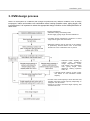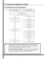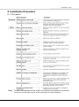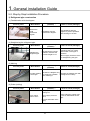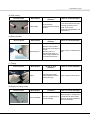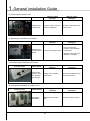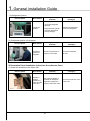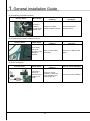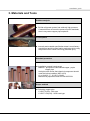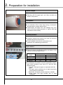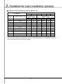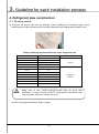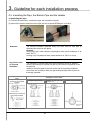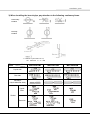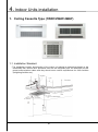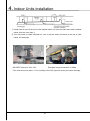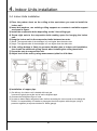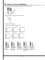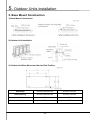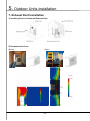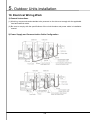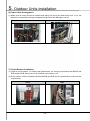
1
Contents 1. General installation Guide 1. Introduction ···························································· 2. Product Outline ······················································· 3. DVM design process ················································ 4. Installation process & Guideline ·································· 5. Installation Procedure ··············································· 4 5 7 8 9 2. Preparation for installation 1. Checking the Installation Site ··································· 25 2. Product handling ···················································· 29 3. Materials and Tools ················································ 39 3. Guideline for each installation process 1. Sleeve work ·························································· 2. Insert work and support work ···································· 3. Concealed Box work ··············································· 4. Refrigerant pipe construction ···································· 5. Refrigerant pipe flushing ·········································· 6. Drainpipe Work ····················································· 7. Insulation work ······················································ 8. Gas leak test ························································· 9. Vacuum drying ······················································ 10. Charging Refrigerant ············································· 47 49 51 52 71 73 82 84 86 88 4. Indoor Units installation 1. Ceiling Cassette Type (1WAY/2WAY/4WAY) ··················· 90 2. Duct Type (Slim/MSP) ············································ 96 3. Ceiling ······························································· 106 4. Console ····························································· 109 5. Wall-mounted Type ·············································· 111 5. Outdoor Units installation 1. Safety Information ·············································· 114 2. Preparing the Installation ········································· 115 3. Selecting Proper Location for Installation ···················· 117 4. Space Requirements ·············································· 118 5. Base Mount Construction ········································ 120 6. Drain Pipe Installation ············································· 123 7. Exhaust Duct Installation ········································· 124 8. Installing the Outdoor Unit Harsh Environments············ 125 9. Louver Installation ·················································· 127 10. Electrical Wiring Work ··········································· 128 11. Pump-Down Operation ·········································· 133 12. Pump-Out Procedure ············································ 134 13. Setting the Option Switches & Function Keys ············· 135 14. Completing the Installation and Commissioning ·········· 136 1. General installation Guide 1. Introduction The following system diagram illustrates overall organization of the refrigerant pipes for installing a system air conditioner. Multiple outdoor units with sufficient capacities are installed in a location with good air ventilation for cooling and heating and a vibration-proof rubber mat is installed in the bottom of the outdoor unit to prevent vibration from being transferred to the building. The refrigerant pipe and the communication cable from the outdoor unit penetrate the outer wall of the building before reaching the inner area of the building. When penetrating the outer wall of the building, sleeves should be used to prevent air leakage and support water proofing. The refrigerant pipes and electrical wiring works for the indoor unit should be finished by fixing the indoor unit in a level or perpendicular location. In the refrigerant pipe works, you should pay attention to installation of insulation materials as well as branch pipes and incline. You should also make efforts to remove all alien substances from the inner area of the pipe. To construct an air conditioning system for the building, you must first design the overall air conditioning system and select components such as chillers and indoor units and refer to the construction design diagram in order to prepare a diagram for installing an air conditioning system. System air conditioner installation vendors should refer to the provided construction diagram when preparing a diagram for installation and purchasing components. If necessary, you should process and weld the copper pipes on site and install your indoor and outdoor units and controllers. 4 Installation guide 2. Product Outline 2-1. Outdoor Units Samsung provides you the perfectly optimized cooling and heating system with its latest and most innovative technology. World’s largest capacity will provide you the powerful performance all year long, no matter how hot or how cold. Furthermore, Samsung’s outdoor units barely make any noise or vibration during operations, and they are perfect for residential and commercial buildings, Always stay refreshed with Samsung system air conditioner. 1) DVM PLUS III, DVM PLUS III HR DVM PLUS III, DVM PLUS III HR is a module multi-system air conditioner that has the world's largest capacity(8~64HP) with the application of a DVI (Digital Vapor Injection) compressor, and can connect up to a maximum of 64 indoor units. • The world's largest capacity. - Compact combinations (8~64 hp) : combinations with the models requiring the smallest installation space - High combinations (16~56 hp) : combinations with highly efficient models • The highest cop levels in the industry • The smallest installation space requirement in the world • The highest heating capacity and cop in low temperature condition (-10°c) • Possible to connect up to 64 indoor units • Digital unit module 5 1. General installation Guide 2-2. Indoor Units Samsung indoor units are not only equipped with high performing functions, but they are also beautifully designed to enlighten your space. Different types of indoor units will be more than enough to satisfy needs of your space and yourself. Only Samsung’s beautiful indoor units will provide you the conditioned air that you can enjoy. 6 Installation guide 3. DVM design process DVM is a multi-system air conditioner that changes its performance by different conditions such as design temperature, indoor and outdoor unit combination rates, heating operation rates, piping length, and level difference. It is important to select the appropriate design condition to the load specification of each room. • Design temperature • Calculate cooling and heating loads • Power supply, piping length and level difference • Consider design temperature conditions to select larger indoor types than actual load. • Determine outdoor units by the sum of the capacity of preliminary selected indoor units: At this time, decide how much combination ratio to permit. • Calculate actual capacity of outdoor units considering design temperature, indoor and outdoor unit combination ratio, piping length, level difference, heating operation rates, etc. • Calculate actual capacity of each indoor unit based on the calculated outdoor capacity. • If Indoor units’ actual capacity is lower than the load, reselect ones with a larger capacity. Depending on designers’ own discretion. • If there is no indoor unit with a larger capacity, add another indoor unit. 7 1. General installation Guide 4. Installation process & Guideline Striking a balance between System Installation & General Construction Work. . Note: 1. The division of the work should be thoroughly clarified. (This applies particularly to work relating to the connection of control wiring, fitting of remote controller and central control panel, boundary work on areas such as connection of drain piping and humidification supply piping, inspection and foundation) 2. Keep a constant check on the progress of the construction work to avoid deviations from the air conditioning work schedule. 3. For sleeve and insert work the positions of ceiling girders should be confirmed and sleeve and insert requirement, hole diameters, positioning and numbers decided. This is particularly important in the case of sleeves for drain piping. 8 Installation guide 5. Installation Procedure 5-1. Procedure Note The above list indicates the order in which the individual work operations are normally carried out but this order may be varied according to the local conditions. 9 1. General installation Guide 5-2. Step by Step Installation Procedure 1) Refrigerant pipe construction (1) Familiarization with the diagram Process photo Work details Measure the actual construction diagram. Things to obey (installer) Familiarize with the construction diagram. Items to check (manager) Fully familiarize with the diagram to prevent problems while working on the site. (2) Straightening the refrigerant pipe Process photo Work details Straighten the refrigerant pipe. Things to obey (installer) Considering the job site condition, measure the accurate length to cut. Items to check (manager) - Remove sharp object or something that can cause deformation of the pipe in advance. - Do not apply excessive force for straightening the pipe. (3) Marking Process photo Work details Things to obey (installer) Items to check (manager) Consider the diagram and Accurate marking Compare the marked area with the actual site condition of the length. the diagram accurately. when marking it. (4) Cutter (cutting) Process photo Work details Use a copper cutter to cut it. Things to obey (installer) - Use proper Size & Quality Cutting tool - Do not apply excessive force. (Prevent deformation of the pipe.) 10 Items to check (manager) While cutting the copper pipe, check for deformation of the pipe. Installation guide (5) Pipe cutting Process photo Work details Things to obey (installer) Items to check (manager) - Check if foreign substances are removed from the pipe. Cut the pipe. Prevent foreign substances from entering (If foreign substances are found, it can cause the pipe. performance degradation and malfunctions.) (6) Removing burr Process photo Work details Removing burr Things to obey (installer) Items to check (manager) - Remove burrs so that the cut side of the pipe is smooth. Check for burr residuals in the - Remove burr in a pipe. downward direction to keep foreign substances from entering the pipe. (7) Taping Process photo Work details Taping Things to obey (installer) Tape the pipe to keep foreign substances from entering the pipe. Items to check (manager) Check if taping is done firmly. (8) Ready for piping works Process photo Work details Work completed. Things to obey (installer) Store it in a safe place to prevent damage. 11 Items to check (manager) Store the pipe in a safe place not affected by other works. Remove all other substances from surroundings. 1. General installation Guide (9) Anchor works Process photo Things to obey (installer) Work details Refer to the approved construction diagram when marking the indoor unit installation locations and make a hole for anchor installation. Items to check (manager) - Prevent scattering. Familiarize with the construction diagram. - Use a reel wire support. - Accurate location marking - Safeguard against falling accidents. (10) Full threads bolt and C-channel fixing Process photo Things to obey (installer) Work details Fixing the full threads bolt and the c-channel. - Prevent twisting of the pipe. - Do not damage the insulation materials. Items to check (manager) - Check for pipe damage. - Check interferences. - Obey the separation of the channels. (1.2 to 1.5 meter) 2) Refrigerant pipe construction (branch pipe works) (1) Preparing a branch pipe Process photo Things to obey (installer) Items to check (manager) Prepare a branch pipe. Check for damage in the branch pipes. Things to obey (installer) Items to check (manager) Work details Preparing a branch pipe. (2) Connecting the branch pipes Process photo Work details Check the connection. Connecting the branch pipes. When making a connection, do not apply excessive force that might damage the pipe. 12 Use Branch kit for the pipe connection. (Damage and exterior tests on the branch pipes.) Installation guide (3) Brazing the branch pipes Process photo Things to obey (installer) Work details Brazing the branch pipe. - Nitrogen substituted brazing works on the branch pipe to prevent generation of foreign substance/oxide - Check for adequate pressure (0.01 to 2 0.1kg/cm ) Items to check (manager) Check the pressure and entry of nitrogen. 3) Refrigerant pipe works (air tightness works) (1) Entry of nitrogen Process photo Things to obey (installer) Work details Entry of nitrogen. Inject nitrogen at the proper pressure. Inject nitrogen to st 2 1 : 10kg/cm the pipe to test nd 2 leakages. 2 : 41kg/cm Items to check (manager) In the presence of the manager, check air tightness. Fill out the check forms. (2) Processing the end of the pipe Process photo Things to obey (installer) Work details Wrap the end of the pipe before connecting the equipment, so that nitrogen won’t escape. Sufficient brazing on the end of the pipe. Items to check (manager) Visual inspection (3) Pressure meter displays Process photo Things to obey (installer) Work details st Mark the 1 and nd 2 pressure to see if it leaks. st 1 : 10kg/cm nd 2 2 2 : 28kg/cm look at the scale. 13 Items to check (manager) Check for leakages. 1. General installation Guide (4) Insulation of the branch pipe Process photo Things to obey (installer) Work details Heat-preserve the pipe if there is no nitrogen leakage. Check for leakages. Items to check (manager) Check for leakages. (5) Insulation of the branch pipe Process photo Things to obey (installer) Work details Heat preservation of the branch pipe Items to check (manager) Dense fill up to prevent Check the heat preservation missing heat preservation condition. material and swelling. (6) Levelness adjustment of the branch pipe Process photo Things to obey (installer) Work details Check the levelness of the pipe. Do not exceed the levelness limit of 15 degrees. Items to check (manager) Check the levelness condition. 4) Drainpipe construction (1) Inserting the heat preservation materials Process photo Things to obey (installer) Work details Insert the insulation materials into the PVC pipe. Do not damage the heat preservation materials. 14 Items to check (manager) - Check for damage in the heat preservation materials. - Check for damage in the pipe. Installation guide (2) Mounting the drainpipe Process photo Things to obey (installer) Work details Fix the drainpipe in the channel or hanger. A group of two person should work on the pipe (not using excessive force). Items to check (manager) Check the channel/hanger fixing intervals (1.5m or less) (3) Checking the drain slope Process photo Things to obey (installer) Work details Checking the gradients. Obtain good slope to facilitate smooth drainage of the condensed water. (1/100) Items to check (manager) Check the slope. (4) Pipe connection Process photo Things to obey (installer) Work details Connect the pipes only if there is no leakage. (Drainpipe in each region) Apply sufficient bond to the pipe. Items to check (manager) - Do not perform in the winter season. - Use Standard Quality bond. (5) Pipe connection and socket works on the indoor unit side Process photo Things to obey (installer) Work details Use the drainpipe components for the location that the indoor unit is connected to. Check the height and maintain the drain slope while performing the work. 15 Items to check (manager) Check the height. 1. General installation Guide (6) Pipe work on the indoor unit side Process photo Things to obey (installer) Work details Pipe work on the indoor unit side. Obtain a slope (1/100) Items to check (manager) Check the slope. (7) Vent installation Work details Things to obey (installer) Install a vent to facilitate smooth drainage of water. Install one unit at the end of the equipment. Work details Things to obey (installer) Process photo Items to check (manager) Check vents installation. (8) Water soaking test Process photo Pour the water in the uppermost area to test it. Check the pipe slope. If there is a problem, readjust the slope. Items to check (manager) Check the slope and test water leakage. (9) Connecting the vertical pipe Process photo Things to obey (installer) Work details If there is no problem in the above items, connect the vertical pipe. - Secure bonding works. - Good heat preservation works. 16 Items to check (manager) Must check the pipe pit’s inner area before finishing the wall. Installation guide 5) Power communication works (1) Power cable pipe works Process photo Things to obey (installer) Work details Place a power cable pipe in the correct location. Use Standard quality materials. Items to check (manager) Check for bending of the pipe. (2) Inserting cables Work details Things to obey (installer) Items to check (manager) Insert the standard power communication cable in the pipe. Be careful not to damage the cable while inserting it. Check the cable condition. Work details Things to obey (installer) Items to check (manager) Select an accurate location (check the diagram and onsite measurement) Fully familiarize with the diagram and mark accurate locations. Select a location with a laser point. Check if it is in accordance with the diagram. Process photo 6) Indoor unit installation (1) Location determination Process photo (2). Fastener / Anchor Bolt Process photo Things to obey (installer) Work details Anchor works on accurate points. - Anchor drilling - Full threads bolts mounting 17 Items to check (manager) Check the condition of the full thread bolts. 1. General installation Guide (3) Connecting the equipment Process photo Things to obey (installer) Work details Mounting an indoor unit. A group of two works on the indoor unit. Items to check (manager) Check for levelness of the indoor unit and damage to the indoor unit. (4) Inserting a vibration-proof rubber mat Process photo Things to obey (installer) Work details Insert a vibration proof rubber mat between the bolt and the indoor unit to prevent transfers of the vibration. Items to check (manager) Do not allow the vibration proof rubber mat to be Check the insertion condition inclined toward either of the vibration proof rubber side. Do not omit any of mat. them. (5) Check the horizontal height Process photo Things to obey (installer) Work details Adjust the horizontal height. Check the levelness condition of the indoor unit. Items to check (manager) Considering the ceiling finishing line, check your installation. (6) Installation completed Process photo Work details Things to obey (installer) Items to check (manager) - - - 18 Installation guide (7) Connecting the power communication cables Process photo Things to obey (installer) Work details Connect the power communication cable to the indoor unit. Use a ring terminal to make a connection. Items to check (manager) Check if the ring terminal is used. (8) Insulation works Process photo Things to obey (installer) Work details Pipe insulation works. Do not damage the insulation materials. Items to check (manager) Check the heat preservation and the slope. (9) Insulation works Process photo Things to obey (installer) Work details Indoor unit wrapping. Wrap the indoor unit with polythene to avoid any dust, due to other work progress in the vicinity. Items to check (manager) Check the indoor unit wrapping status. 7) Outdoor unit installation (1) Vibration-proof board installation Process photo Things to obey (installer) Work details Mount the outdoor machine in the correct location by referring to the diagram. - Acquire levelness of the vibration proof board. - Accurate measurement and safe mounting. 19 Items to check (manager) Check if it is in accordance with the diagram. Check the levelness. 1. General installation Guide (2) Conveying the outdoor unit Process photo Things to obey (installer) Items to check (manager) A group of four move the outdoor unit(22HP) Check for damages in the outdoor unit. Work details Checking the outdoor unit. (3) Mounting the vibration-proof board Process photo Things to obey (installer) Work details Mounting the vibration-proof board. Install it in the upper area. Items to check (manager) - Do not change the location of the vibrationproof board. - Check the location in the diagram once again. (4) Connecting the vibration-proof board Process photo Things to obey (installer) Work details Connect the outdoor unit to the vibrationproof board. Bolting of the vibrationproof board. Items to check (manager) Check bolt installation and the final levelness. (5) Completed installation of outdoor units Process photo Things to obey (installer) Work details Completed installation Reinforce the outdoor unit. 20 Items to check (manager) Check for reinforcement. Installation guide (6) Connecting the outdoor unit’s pipes Process photo Things to obey (installer) Work details Connecting the outdoor unit’s pipe. Connect the pipe to the outdoor unit and perform heat preservation. Items to check (manager) Check the heat preservation of the outdoor unit. (7) Vacuum works Process photo Work details Things to obey (installer) Create vacuum inside the pipe. Connect a vacuum pump to the service valve of the outdoor unit and create vacuum all (Discharge, Suction & Oil) line. Work details Things to obey (installer) Items to check (manager) Check the vacuum condition. (8) Checking the vacuum gauge Process photo Check the vacuum gauge condition. Continue the vacuum. Items to check (manager) Check the normal vacuum gauge. 8) Refrigerant charging (1) Refrigerant calculation Process photo Things to obey (installer) Work details Accurately calculate the amount of refrigerant. - 21 Items to check (manager) Estimate the accurate amount of refrigerant from the diagram. 1. General installation Guide (2) Refrigerant injection Process photo Things to obey (installer) Work details Refrigerant injection - Accurate refrigerant injection - Keep the Gas cylinder vertically downward during charging. Items to check (manager) Estimate the adequate amount of refrigerant. (3) Completed injection of refrigerant Process photo Things to obey (installer) Work details Completed injection of refrigerant Check if the amount of injection is accurate. Items to check (manager) Check the adequate amount. 9) Decoration Panel installation (other than the reference floor) (1) Check the levelness of the indoor unit Process photo Work details Things to obey (installer) Items to check (manager) Maintain a distance between the ceiling and the indoor unit. Use a paper pattern to maintain an adequate separation (adjust the height of the indoor unit). Check the levelness of the indoor unit. 22 Installation guide (2) Panel installation Process photo Things to obey (installer) Work details - Do not apply excessive Panel installation force. - Use a clean glove. Items to check (manager) - Check if the exterior is dirty. - Check for damage. (3) Finish Process photo Things to obey (installer) Work details End Check the levelness and any blade damage. Items to check (manager) Check for twisting and test the entire unit. 10) Test operation (1) Indoor unit address setting Process photo Things to obey (installer) Work details Assign a unique number to the indoor unit. Assign an accurate address to it. Items to check (manager) Check the address of the indoor unit. (2) Outdoor unit address setting Process photo Things to obey (installer) Work details Assign a unique number to the outdoor unit. Assign an accurate address to it. 23 Items to check (manager) Check the address to the outdoor unit. 1. General installation Guide (3) Connecting a interface module Process photo Work details Things to obey (installer) Connect a interface module to the outdoor unit. Assign an accurate interface module number. Items to check (manager) Check the interface module number. (4) Connecting a interface module to S-net Process photo Work details Things to obey (installer) Connecting the S-net program to the interface module. Make a correct cable connection. Items to check (manager) Check the condition of the laptop. (5) S-net connection Process photo Things to obey (installer) Work details Connecting the S-net terminal to the outdoor unit PCB. Check for normal condition. If abnormal, inject refrigerant and request services. 24 Items to check (manager) Check for normal condition. 2. Preparation for installation Installation guide 1. Checking the Installation Site Class Noise vibration Pre-check items Handling methods and rules Reference - Is the place affected by ※ Necessary to install a noises or vibration at all? soundproof wall to prevent - Is the outdoor unit close to noise transfer to houses. a residential area? -Use a gallery for soundproof wall - Is the bottom of the outdoor constructions. unit affected by vibration? Claims for noises Weight Outdoor machine base -Can the installation location withstand the weight of the outdoor unit? - Have you determined the ground base for the outdoor unit? ※ In case of remodeled houses, consider the weight of the outdoor unit and review the columns and the beams for construction. Need to consider the weight. - Base area size: 1.5 times the floor. - Total height: 150mm↑ Wooden palette installation prohibited. -Is the outdoor unit placed Outdoor unit on a flower garden or soil? base (Including the foundation.) ※ In case of soil sands, the ground can get deformed during rain. So make the base with concrete pads or H beams. Ground base Air ventilation -Is the outdoor unit installed in a disclosed area? ※ Need to determine whether to use a discharge duct. ※ CFD (Computational Fluid Dynamics) simulation is available upon request to HQ’s SE. Need to improve the air vent structure. Discharge troubles - Is there any blockage within 2 meters from the discharge plane of the upper area? ※ Need to use a discharge duct. - Is there any blockage within 1.5 meters from the discharge plane of the front area? ※ Need to install a gallery. 25 2. Preparation for installation Class Gallery Upper discharge type Pre-check items - Is the gallery spec suggested? Handling methods and rules - Louver angle should be less than 20° - Opening rate of more than 80%. - Select a louver with a smooth cross section. (Do not use a rainwater prevention louver.) - Can you clear 500 mm(20inch) or more from the front of the outdoor unit and 300mm(12inch) or more from the rear? [Tray and interfering pipes included.] - Can you access the outdoor unit? Front discharge type Reference -Is the service space available? Need some service space. ※ 2 level stacking not allowed. - Possible when the metal frame is used. Height of 300mm(12inch), side of 100mm(4inch) - Can you have more than ※ When the front and the rear are 1500mm(60inch) in front of face-to-face, separate them by the outdoor unit? more than 3,000mm. 2-level stacking prohibited. - Is the outdoor unit located close to a bathroom/ kitchen vent/cooling tower or air vent? - Is the installation location ※ Corrosion in the outdoor unit and close to a beach or hot Corrosion in spring? the pipe lead to refrigerant the outdoor leakage. unit Need another location that is not - Is there another source of affected by the surroundings. corrosion? 〔Methane gas, SO2 gas discharging area, sewage water treatment facility, hot spring, dyeing factory〕 Installation near toxic gas source is prohibited. - Is group installation of ※ Check the CFD simulation. Outdoor unit outdoor unit necessary? installation (Group installation for more - Request to HQ’s SE. than 3 rows.) Installation in group may result in compressor damage 26 Installation guide Class Pre-check items -What is the finishing material for ceiling? Ceiling finishing - Is the ceiling sunken? Handling methods and rules Reference - If the ceiling is made of plaster boards, install an access hole depending on the internal height of the ceiling. -If the ceiling is made of ceiling tile, then no need to install an access hole. ※ Need space at least 500mm(20inch) away from the equipment at sunken part of ceiling Installation at sunken ceiling -Can you install an access hole for interior finishing? ※ Access hole is necessary for - Did you check the work Duct type indoor unit, ERV, scope of access hole Access hole MCU and distribution kit. installation? - Check the access hole size for -Did you notify the access hole each product. size of the duct type indoor unit in advance? Installation -Is the installation space for space the indoor unit sufficient? - Is the 4way indoor unit Installation installed within 3.5 height meter(11.5ft) from the ground? Vertical pipe - Did you review the path for the vertical pipe? ※ Obey the incline and pumping height. - Drain incline (1/100) - Drain pumping height should be less than 750mm(30inch) from the bottom of the indoor unit. ※ When the ceiling height is exceed 3.5m(11.5ft), use a special kit for high ceiling, maximum 5.2m(17ft) or switch to a duct-type indoor unit. ※ Can’t install it in the EPS room or high voltage room. - Must obey the max permitted Horizontal ※ Avoid indoor installation of the pipe length from the initial running pipe brazed joints or the branch pipe. branch. High elevated pipe - Must obey the maximum height between indoor and * As an outdoor unit is located in a outdoor unit. (50 /40m*) lower position than indoor unit, - Must obey the maximum level difference is 40m. height between indoor units. (15m below) 27 - - Inefficient or poor sensible cooling/heating - - - 2. Preparation for installation Class Drain Pre-check items - Is the discharge area free of bad odors? Installation - Is the location of the MCU, or location EEV proper? Handling methods and rules Reference ※ Do not join rainwater pipes and sewage water pipes. If unavoidable, then join them below the first floor to prevent reverse flows into the indoor unit. - ※ If installed near human residence such as living rooms or indoor, it can generate noise. ※ Do not install it in a fire fighting zone. - - Is the power spec or the power receiving capacity good? Power spec Circuit breaker - - Did you correctly deliver the product power spec? ※ In case of 3 phase/380V/50Hz, Clarify whether it is 3 or 4 line type. - Use power spec, ring terminals. - Need to check the additional spec of the indoor power. - Are the circuit breaker’s spec and capacity clear? ※ Criteria for selecting a circuit breaker. - Must install a leakage breaker (ELCB) in the indoor unit’s power system. - Install a leakage breaker (ELCB) for an individual or group of outdoor units. - MCCB 28 ELB Installation guide 2. Product handling Problem analysis Dropping the product, due to rough or careless handling of the product during unloading process. Consequence It will cause the product damage/deformation and may also cause motor fixation kit to fall off. Such consequences will interrupt normal operation of the product and lead to noise generation. Furthermore, severe damages to the electrical parts may cause performance decrease and even serious accident which may involve personal injury. Standard procedure Product is future property of our clients. We must take steps to protect the product while during loading, unloading and transporting process in order to prevent damage and operational/functional problem. Proper method When moving the indoor units, you must form a group of 2 people to move the indoor units together. Move the indoor units slowly with extra care and lift it down gently. You should never drop the indoor units from higher ground or handle them roughly. 29 2. Preparation for installation Problem analysis A chassis of outdoor unit is bent and a heat exchanger of the condenser is damaged due to inappropriate transportation method. Consequence When moving the product, you must lift up and down the product gently. When the product is scratched, product will corrode or get rust. If the heat exchanger of the condenser gets damaged, it will cause deteriorating performance and even make a leakage from the pipe. Standard procedure Since the product is valuable, you must take extra care when moving it. You must protect the product from exterior or structure damage. Proper method When moving with crane : 1) To prevent the surface damage or scratch while moving the product, put 1.5mm thick cloth or other soft material between the product and rope. 2) Use 4 wire ropes From the figure on the left, A > 1.5m 30 Installation guide Problem analysis Product is left alone in the open site. If the ground gets wet with water after rain or due to other reasons, it will cause bad effect on the product. Consequence If the indoor unit products gets soaked, water will damage the packaging first and then it may get into the indoor unit and damage the electrical parts. Such damage may cause critical safety trouble. Standard procedure When leaving the product in the site, you must store them properly. Do not put the product on the ground. You must use some sort of a support, with certain height, underneath the product to prevent the product from getting soaked in water in case of water floods. Proper method Construct a support with at least 200mm(8inch) high above the ground and leave the product on top of those supporting structure. 31 2. Preparation for installation Problem analysis Pile of indoor units in the site is too high and some of the products are even piled up vertically. Consequence Pile may fall down and cause personal injury. Indoor units lying on the bottom of the pile may get damaged due to pressure. Standard procedure Pile cannot be over 6rows and exceed 2m(6.5ft) in height. You cannot pile them vertically either. Proper method 1. Do not pile the indoor units too high. - When the product is lighter than 50kg, pile cannot be over 6 rows. - When the product is heavier than 50kg, pile cannot be over 3 rows. 2. Height of the pile cannot exceed 2m(6.5ft) and you must put the warning signboard around the pile. 32 Installation guide Problem analysis Indoor units are stored vertically. Not only that, it is left on the ground and the ground is wet with large amount of water. Consequence Pile may fall down and cause personal injury. Indoor units lying on the bottom of the pile may get damaged due to pressure. If the indoor units get soaked, water will damage the packaging first and then it may get into the indoor unit and damage the electrical parts Standard procedure Store the indoor units horizontally. Do not leave them vertically. Proper method Store the indoor units horizontally (or horizontally piled up) with the supporting structure at least 200mm(8inch) high underneath the product. 33 2. Preparation for installation Problem analysis Products are stored messily in the site and there is no manager in charge. Consequence Products are bumped into each other and pressed by one another which cause structural deformation. Internal parts of the product may get damaged or even lost. Standard procedure When storing the indoor unit : 1. Do not mix different models. 2. Do not leave them upside down. 3. Do not leave them vertically. 4. Do not tilt the indoor units. 5. Do not exceed standard height when storing them in pile. Proper method Assign exclusive manager to manage. And store each models on the supporting structure at least 200mm(8inch) high. 34 Installation guide Problem analysis Inappropriate product management caused outer packaging damage. Consequence After damage to the outer packaging of indoor unit, dust and other foreign substances entered to the product. Furthermore, you may lose <Installation manual>, <User manual>, drainpipe or other parts needed for installation. Standard procedure Strictly regulate the package removal before installing the indoor units. Manage and keep all the related parts and manuals thoroughly. Proper method After indoor units arrive in the site, do not remove the package until it is being installed. When removing the package upon the installation of the product, keep the manuals separately and use other accessories (such as drainpipe) properly. Take extra care to prevent from losing them. 35 2. Preparation for installation Problem analysis Indoor unit installation is put on hold, and it was left with all the packaging removed. Dust, foreign substances, rain water, industrial water and dew got inside of the indoor unit. Because it was left with all the packaging removed while installation was put on hold. Consequence Dust and other foreign substances will get inside and cause pipe blockage or other malfunctions. Standard procedure After indoor unit arrives in the site, do not remove the packaging until it is being installed. If the installation was stopped or put on hold for any reasons, wrap the indoor units for protection. Proper method Protect the indoor unit by wrapping it. 36 Installation guide Problem analysis Indoor unit, which is still in the middle of the installation process, is hanging on the ceiling without any protection. Consequence Indoor unit was hanging on the ceiling without any Protection which allows dust and other foreign substances to enter and cause malfunction. Standard procedure Wrap the indoor unit with vinyl Proper method Wrap the indoor unit with vinyl if the installation is still in process to prevent dust, foreign substances and water from entering. 37 2. Preparation for installation Problem analysis Safety net is not installed on 4-way cassette indoor unit. Consequence Safety of client and service agent can be at risk. Standard procedure Install the safety net for safety reasons. Proper method Make sure safety net is installed and let the customer know that they must not remove them for their own safety. 38 Installation guide 3. Materials and Tools Problem analysis R410a refrigerant system has relatively high pressure. If material does not meet the pressure-proof standards, then it may cause copper pipe explosion. Consequence Intensity and material specification doesn’t meet factory requirement and this could lead to explosion while using the product which could even bring personal injury. Standard procedure Installation material requirement Material : phosphorous deoxidized copper, purple copper pipe Analysis result shows that chemical component should meet the below condition (KSD 1651) Cu ≥ 99.90% ; P : 0.015%~0.040% Mechanical properties need to meet KSD 5301 Proper method Selecting copper pipe C1220T-O(JIS) : Soft type C1220T-1/2H(JIS) : Semi-hard type 39 2. Preparation for installation Problem analysis Layer of carbon, rust and dirty foreign substances were found on the outer surface of the copper pipe. Pipes must not have any scratches, indents or stains etc. Consequence Such defects decrease the strength of the pipe which may result in explosion, decrease in performance or leakage. Standard procedure You must select clean and dry copper pipe. Check inside of the pipe for any dust, water, indents or any signs of damage. Proper method Select a copper pipe according to the standards. 40 Installation guide Problem analysis Due to inappropriate protection management of the internal/external surface of the copper, large amount of oxidation, dust and foreign substances were seen. Consequence R410a refrigerant is very sensitively react with foreign substances : Mineral oil and compress oil will not solve with each other due to different chemical characteristics. Therefore, wax type materials may clog the hole of EEV or oil filters. Standard procedure Check if it is clean enough. Foreign substances in the copper pipe < 30mg/10m R410a copper pipe must be kept clean until it is installed. Proper method Select the clean copper pipes and make sure no dust or foreign substances get into the pipe when you keep them. If the copper pipes are stored for a long period of time, clean them(blow Nitrogen) before installation to remove undesired material from inside of the pipe 41 2. Preparation for installation Problem analysis After purchasing the pipe, it was not kept properly so dust, foreign substances, water and industrial water got inside of the pipe. Also pipe was left on the ground and people just walked on them. Consequence Water or foreign substances within the pipe will cause blockage that can lead to product malfunction or performance decrease. Standard procedure When storing the pipe, use cover or tape to block the entrance and do not leave them on the ground but keep them on the supporting structure with at least 30mm in height. Proper method Strictly follow the standards. 42 Installation guide Problem analysis Thickness of the pipe does not meet the standards. Consequence Strength and the duration of the pipe will decrease which may cause breakup. Especially, R410a is a high pressure gas. Pipe with less thickness will have less strength, which may cause the pipe breakup. Standard procedure Required thickness – Soft type Outer diameter(mm) Min. Thickness(mm) Ø6.35 0.8 Ø9.52 0.8 Ø12.70 0.8 Ø15.88 1.0 Required thickness – Semi hard type Outer diameter(mm) Min. Thickness(mm) Ø19.05 0.9 Ø22.23 0.9 Ø25.40 1.0 Ø28.58 1.1 Ø31.75 1.1 Ø38.10 1.35 Ø44.45 1.6 Ø50.80 2.0 Proper method Select the pipe according to above specification 43 2. Preparation for installation Problem analysis Selecting ø22.23 copper pipe, and 10mm insulation as shown in the picture. Consequence Low insulation effect cause large energy consumption and decrease in system performance. Condensation will easily form and leakage may occur when performing heating operation in regions with high temperature and humidity. Standard procedure Insulation material and quality must meet the minimum standard thickness requirements. Good installation will prevent condensation and guarantee air conditioning performance. Proper method Follow the below specification strictly and aware of the Minimum thickness requirements. Pipe size [mm] Ø6.35~19.05 Ø22.23~31.75 Ø38.10 Ø44.45~ Minimum thickness of insulation [mm] PE foam EPDM foam 13 10 19 13 25 19 32 25 The thickness of insulation must be increased in case of high humid conditions (over than 27°C and RH 80%) like below place - Tropical / Subtropical regions or equivalent with this region - The region where problems due to high temperature and humidity are expected - Restaurant, hot spring, sauna, basement, seaside - Ceiling inside with high humidity due to weak ventilation 44 Installation guide Problem analysis Regular vacuum pump was used in vacuum operation. Consequence If the power of the vacuum pump cuts off unexpectedly then the oil gets back to the refrigerant system due to pressure difference. Standard procedure Use the vacuum pump which is 100% dedicated for R410a system with stop valve. Proper method Purchase and use the vacuum pump with the stop valve. 45 2. Preparation for installation Problem analysis R22 gauge was used in R410a system. Consequence If you use R22 gauge, remaining oil inside can generate wax type material which definitely badly affect POE oil of R410a system, possibly clogging refrigerant passage or causing compressor failure. Standard procedure Never utilize R22 gauge for R410a system to prevent the mineral oil from flowing in to the R410a system. Use the measuring instruments that meets the standard requirement. High pressure side : -0.1 ~ 5.3MPa Low pressure side : -0.1 ~ 3.8MPa Proper method Install in accordance with the standards. 46 3. Guideline for each installation process Installation guide 1. Sleeve work 1-1. Positioning of the pipe holes 1) The through holes for the drain piping should be positioned such that the pipes have a downward gradient. (The gradient must be at least 1/100. The thickness of the insulating materials must also be taken into consideration.) 2) The diameter of the through holes for the refrigerant piping should include allowance for the thickness of the heat insulation materials. 3) Attention should be paid to the construction of the beam themselves since there are sometimes parts of the beam which cannot be used to accommodate through holes. 1-2. Selection of sleeve 1) Sleeve work should be performed to make a space for passing pipe and wire through the wall or ground under construction 2) Use of shielded transmission cable is recommended to avoid the problem of electrical noise 3) Depending on the selected product or the installation environment, if the insulation material’s thickness is subject to change, then additional calculations are necessary. Sleeve diameter [mm] = (Liquid pipe diameter+ insulation material thickness x2) + (Gas pipe diameter + insulation material thickness x2) +20 4) Maintain a minimum separation of 10mm between the pipes to facilitate smooth air flows. (To prevent dew forming) 47 3. Guideline for each installation process ※ Selection of the refrigerant pipe sleeve’s diameter (a) Classification Liquid pipe diameter(mm) 6.35 9.52 Insulation (Based on 9t) 12.7 15.88 19.05 Insulation (Based on 13t) 22.22 32.35 24.35 77 27.52 80 38.7 91 41.88 94 45.05 97 48.22 101 9.52 47.52 92 95 106 109 113 116 12.7 50.7 95 98 109 113 116 119 15.88 53.88 98 101 113 116 119 122 19.05 57.05 101 105 116 119 122 125 22.22 60.22 105 108 119 122 125 128 25.4 63.4 108 111 122 125 128 132 28.58 66.58 111 114 125 128 132 135 31.75 69.75 114 117 128 132 135 138 38.1 76.1 120 124 135 138 141 144 44.45 82.45 127 130 141 144 148 151 Gas pipe diameter (mm) Gas pipe diameter + Insulation (based on 19t) 6.35 ※ If the insulation material’s thickness is subject to change depending on the installation location, you must reselect a new sleeve pipe diameter. 48 Installation guide 2. Insert work and support work 2-1. Insert work Example : Through holes in a reinforced concrete beam Full thread bolt works 49 3. Guideline for each installation process 2-2. Support work 1) Installation guideline for a vertical piping ▶ Down-stopper fixing guide Height Fixing interval Remarks 1 lower Fix a pipe every 5m(16.5ft) If there is a pit, fix a pipe at each floor 2 Higher than 15m Install a down stopper every 3floor or every 15m height Pipe must be fixed at every 5m ※ How to fix a pipe - Utilize “U” shape volt or circular band on the insulation of the pipe Fixing with a circular band Fixing with a Down-stopper 2) Down-stopper installation ① Attaching the Down-stopper part to the vertical pipe Attaching the down stopper to the vertical pipe ⑤ Finished sample ② Brazing work ③ Assembly of wall contact Heat uniformly until a base metal become cherry red in color than apply a filter metal ④ Insulating a pipe Tightly wrap the insulation with a finishing tape 50 Assembled sample Installation guide 3. Concealed Box work 3-1. Concealed Box work 1) Objectives - The concealed box aims at enhancing the interior inside the building by burying the drains, the copper pipes, the insulation materials, and the wires in the earlier phase, when you need to install an indoor unit 2) Functions (1) Buried in the wall on the pipe installation site and connecting the pipes, the drains and the wires. (2) Copper pipe protection, enhancing the exterior. (3) Mounting a pressure gauge to check the air tightness at any time. Concealed box Buried box connection board 51 3. Guideline for each installation process 4. Refrigerant pipe construction 4-1. Drawing review 1) Compare the actual site with the drawing. When installing the refrigerant pipes, check interferences and the requirements for each pipe diameter size/length/quantity ahead of time. Temper grade and minimum thickness of the refrigerant pipe Cautions Outer diameter Minimum thickness 6.35 0.7 9.52 0.7 12.70 0.8 15.88 1.0 19.05 0.9 22.23 0.9 25.40 1.0 28.58 1.1 31.75 1.1 38.10 1.35 44.45 1.6 50.80 2.0 Temper grade C1220T-O C1220T-1/2H Or C1220T-H Make sure to use C1220T-1/2H(Semi-hard) pipe for more than ∮19.05mm. In case of using C1220T-O (soft) pipe for ∮19.05mm, pipe may be broken, which can result in an injury. (2) Soft or hard pipes (Annealed, Drawn temper) 52 Installation guide 2) Preparing a pipe (1) On the drawing, check the pipe diameter/length and the insulation material’s thickness and length. Prepare some margins for the dimension shown in the drawing (to give elastic tensions), Use a special cutter to cut the pipes. 3) Check the quantities of the branch pipe/header and the outdoor unit’s branch pipes. (1) Additionally purchased items Type Y-joint Y-joint (Only for DVM plus Ⅲ HR module) Model MXJ-YA1509* MXJ-YA2512* MXJ-YA2812* MXJ-YA2815* MXJ-YA3119* MXJ-YA3819* MXJ-YA4422* MXJ-YA1500* MXJ-YA2500* MXJ-YA3100* MXJ-YA3800* MXJ-HA2512* Header Joint Outdoor Joint Outdoor Joint (Only for DVM plus Ⅲ HR module) MXJ-HA3115* MXJ-HA3819* MXJ-T3819* MXJ-T4422* MXJ-T3100* MXJ-T3800* 53 Total capacity 15.0kW below 15.0~40.6kW 40.6~46.4 kW 46.4~69.6 kW 69.6~98.6 kW 98.6~139.2 kW 139.2 kW and over 23.2kW and below 23.2~69.6 kW 69.6~139.2 kW 139.2 kW and over 46.4kW and below(For 4 rooms) 69.6kW(For 8 rooms) 69.6kW and over (For 8 rooms) 48HP and below 50HP and over 48HP and below 50HP and over 3. Guideline for each installation process 4-2. Pipe Cutting 1) Burring - When performing burring works, point the pipe face downward to prevent entry of burr. 2) Taping – To prevent entry of moisture or dust, seal off the pipe completely. 54 Installation guide Covering is an extremely important operation as it prevents water, dirt or dust from getting inside the pipes. Moisture inside the pipes was a constant source of trouble in the past. The utmost care is required to nip this problem in the bud. The end of each pieces of pipe must be covered. “Pinching” is the most effective method but “taping” is an simple alternative which may be used according to the work area and term of work. Location Outdoors Indoors Term of Work Covering Method 1 months or more Pinching Less than 1 months Pinching or taping Irrelevant Pinching or taping ① Pinching method The end of the copper pipe is squeezed together and the gap brazed. ② Taping method The end of the copper pipe is covered with PVC tape (vinyl tape). <Taping method> Particular care should be taken during the following operations: • When passing copper pipe through a penetration hole (Dirt easily gets into the pipe). • When copper pipe is located outside (Rainwater gets in) (Special care is needed when the pipes are standing vertically outside) 55 3. Guideline for each installation process 4-3. Insulating the Pipe, the Branch Pipe and the Header 1) Insulating the pipe (1) To block off external air, insulate the pipe with insulation material. (2) Insert the insulation material into the pipe and use a special EPDM glue to finish it. Materials Essential Points of Thermal Insulation Example of incorrect work Gas and liquid piping should not be insulated together The thermal insulation materials which are used must be well able to withstand the heat from the pipes. Example : Heat pump type: Heat resistant polyethylene foam (heat resistance of at least 120°C) Cooling only: Polyethylene foam (heat resistance of 100°C or more) The insulation of jointed areas such as the soldered, flared or flanged sections should only be carried out after the successful completion of the air tight test. Attention should be paid to the unit model and its operating conditions since there are occasions when the gas and liquid pipes also need to be thermally insulated. Example of correct work Insulation of both gas and liquid pipe only Insulation of gas pipe only Jointed areas must also be thoroughly insulated ▶ Important points 56 Insulation of support brackets Installation guide ① The thickness of the thermal insulation material must be determined in the light of the pipe sizes. Pipe size in. (mm) Thickness of insulation material Pipe size in(mm) Thickness of insulation material 1/4~1 (6.4mm~25.4mm) 1/2 or more (12.5mm or more) ② It will be necessary to increase the values in the above table for top floors or where conditions are hot and humid. (Refer to Installation manual "6-5 Pipe insulation" for more detail) ③ Where a customer supplies his own specifications then these must be adhered to. ④ Where it is anticipated that the air conditioning unit will be operated at external air temperatures of 10°C or less then thermal insulation will also be required for the liquid pipes. Heat Recovery Series • Suction, Discharge Gas piping, liquid piping must be insulated. • Example of thermal insulation work. 3 piping section (between outdoor unit and MCU unit) 2 piping section (between MCU unit and indoor unit) • If you think that the humidity around the cooling piping might exceed 86°F and RH80%, reinforce the insulation on the cooling piping (at least 13/16" thick). Condensation might form on the surface of the insulation. 2) Insulating the refrigerant pipe (1) Insulating the refrigerant • You must check if there is a gas leak before completing all the installation process. • Use EPDM insulation which meets the following condition. Item Unit g/cm3 % Standard 0.048~0.096 -5 or less g/cm3 0.005 or less Thermal conductivity kcal/m·h·˚C 0.032 or less Moisture transpiration factor Moisture transpiration grade ng/(m²·s·Pa) g/(m²·24h) 15 or less 15 or less mg/L - % 25 or less Density Dimension change route by heat Water absorption rate Formaldehyde dispersion Oxygen rate 57 3. Guideline for each installation process (2) Selecting the insulation of the refrigerant pipe • Insulate the gas side and liquid side pipe referring to the thickness according to the pipe size. • The thickness according to the pipe size is calculated at the indoor temperature of 27°C and humidity of 80%. If installing in an unfavorable conditions from it, use thicker one. Pipe size (mm) Minimum thickness of insulation (mm) Remarks PE foam EPDM foam ø6.35~19.05 13 10 ø22.23~31.75 19 13 ø38.10 25 19 - 32 25 If you install the pipe underground, at the seaside, a spa or on the lake, use thicker one according to the pipe size. (3) Insulating the refrigerant pipe • Be sure to insulate the refrigerant pipe, joints and connections with class ‘o’ material. • If you insulate the pipes, the condensed water does not fall from the pipes and the capacity of the air conditioner is improved. • Check if there are any insulation cracks on the bent pipe. Pipe insulation Pipe insulation after insulating EEV kit • Insulation of the gas and liquid pipes can be in contact with each other but they should not be pressing each other. • When contacting the gas side and liquid side pipe, use thicker insulation. • When installing the gas side and liquid side pipes, leave 10mm of space. • When contacting the gas side and liquid side pipe, use thicker insulation. Insulating the refrigerant pipe • Install the insulation not to be get wider and Cautions use the adhesives on the connection part of it to prevent moisture entering. • Wind the refrigerant pipe with insulation tape if it is exposed to outside sunlight. • Install the refrigerant pipe respecting that the insulation does not get thinner on the bent part or hanger of pipe. 58 Installation guide (4) Insulating the branch joint Y-joint & liquid side of the outdoor unit • Attach the insulation provided with a branch joint to the insulation purchased individually without a gap. Wrap the connected part with an insulation (purchased in the market) of a thickness of at least 10mm. • Use an insulation that should be able to handle the interior temperature over 120°C. Wrap the branch joint with an insulation of a thickness of at least 10mm. Header joint • Fasten the header joint using a cable tie and cover the connected part. • Insulate the header joint and the brazed part and wrap the connected part with an adhesive insulation tape to prevent it from defrosting. • Before starting the insulation work on joints(brazed part), ensure that the e)pressure test is done (no leakage) Fix the header joint after insulating it. . 59 3. Guideline for each installation process 4-4. Mounting the Pipe, the Branch Pipe and the Header 1) Mounting the insulated pipes. – The liquid/gas pipes should be made as a pair and the branch pipes require step differences with each other. 2) Install a hanger before and behind the branch pipe. - Install a hanger before and behind the branch pipe. 60 Installation guide 3) When installing the branch pipe, pay attention to the following cautionary items. Horizontally installed Vertically installed Install the Y-joint within ±15° on the horizontal or on the Model Name MXJ-HA2512* MXJ-HA3115* Liquid side Gas side Insulation (Liquid side/Gas side) Liquid Side Socket Gas side 61 MXJ-HA3819* 3. Guideline for each installation process Header joint ① Select the reducer fitted on the diameter of the pipe. ② Braze the pipes ends with caps if the number of connected indoor unit is fewer than header joint ports. < Liquid side > < Gas side > • When using A~J type of header joint, connect the header joint to the pipe with provided reducer. Cautions • When using K~Z type of header joint, connect the header joint to the pipe by cutting the provided reducer properly. • Connect the header joint in order respecting the number of the indoor unit. • Connect the indoor unit as the highest capacity comes first. ③ Install the header joint horizontally. - Install the header joint horizontally so that it is not facing down. < Liquid side > Note < Gas side > Incorrect installation of Y-joint and header joint cause poor oil and refrigerant distribution between indoor units. It may decrease the system’s performance or cause compressor failure. 62 Installation guide 4) Installing the branch joints Outdoor joint Installation of outdoor joint Use the attached reducer properly according to the selected pipe size. <Liquied pipe > <Gas pipe, High pressure gas pipe> Note • When using A~J type of Outdoor joint, connect the Outdoor joint to the pipe with provided reducer. • When using K~Z type of Outdoor joint, connect the Outdoor joint to the pipe by cutting provided reducer properly. 63 3. Guideline for each installation process 4-5. Connecting the Pipe/Branch Pipe 1) Reducer mounting - When connecting the pipes/branch pipes, you need a reducer to compensate for the diameter differences. The following specs are applied. Y-Joint Model Name MXJ-YA1509* MXJ-YA2212* MXJ-YA2512* MXJ-YA2815 MXJ-YA3119* MXJ-YA3819* Liquid side Gas side Insulation (Liquid side/Gas side) Liquid Side Socket Gas side 2) Reducer mounting methods - If the pipe is inserted deep into the reducer, it can cause refrigerant noises, so be careful. 64 Installation guide 4-6. Installing the Branch Pipe for the Outdoor Unit 1) Connecting the outdoor unit pipe Heat Pump Working process Connection from front side Connection from bottom at the left/right side Working process • Separate the knock-out hole at the • First, remove the cover from unit. • Separate the knock-out hole to use. If bottom side of the unit and install the the hole is open, small animals such pipe. as squirrels and rats may get into the • After installing and insulating the unit through the hole and the unit pipe, close up the remaining gap. If the gap is remain open, small may be damaged. • Fix the pipe cover of bottom side and animals such as rats and squirrels fix the pipe cover of upper side may get inside the unit and cause thereafter. damage to the unit. Single Installation Combination installation 65 3. Guideline for each installation process Heat Recovery Connection from front side Connection from bottom at the left/right side Single Installation Combination installation Caution for connecting the pipe Cautions • When connecting the pipe to the unit, the unit may get damaged by a brazing fire and a flame. Use a flame proofing cloth to protect the unit from a brazing fire or flame. Ambient air temperature sensor for detecting outside temperature is located on the left side of the welding part. Make sure not to damage the temperature sensor when welding it. • The O-ring and Teflon packing inside service valve may get damaged by a welding fire. Wrap the bottom side of the service valve with a wet cloth and weld it as shown above. Make sure not to interrupt the brazing with the drops of the wet cloth. • The connecting pipes of liquid side and gas side should not contact each other. Vibration may cause a damage to the pipes. 66 Installation guide 2) Piping works among outdoor units • The additional branch joints are needed for module installation of the outdoor units. • When outdoor units are installed in module, there is no designation of outdoor unit’s location according to capacity. • The connected piping should be positioned at the same or lower level with pipe cover hole. Cautions Correct piping work The refrigerant piping should be the same level or lower than connecting position of piping to outdoor units. Piping work should be run with side direction for better uniform distribution of refrigerant and oil like next diagram. Outdoor joint kits should be installed in a horizontal direction, even it is a low pressure pipe. When the piping length between outdoor and branch joints is 2m or more, a vertical trap has to be installed like right diagram. 67 Wrong piping work 3. Guideline for each installation process 4-7. Brazing 1) Nitrogen substituted welding (1) Perform nitrogen substituted brazing works. Brazing the pipe • Make sure that there is no moisture inside the pipe. • Make sure that there are no foreign materials and impurities in the pipe. • Make sure that there is no leak. • Make sure to follow the instruction when brazing the pipe. The use of Nitrogen gas ① Use Nitrogen gas when brazing the pipes as shown in the picture. ② If you do not use Nitrogen gas when brazing the pipes, oxide may form inside the pipe. It can cause the damage of the compressor, valves. ③ Adjust the flow rate of the Nitrogen gas with a pressure regulator to maintain 0.05m3/h or less. Direction of the pipe when brazing • Performing the brazing of the pipe should be headed downward or horizontally. Note Avoid brazing the pipe upward. Nitrogen substitution for prevention of copper pipe corrosions 68 Installation guide 2) Comparison with a case without nitrogen substitution With Nitrogen substitution Without Nitrogen substitution 3) Precautions for pipe-to-pipe brazing works Brazing work should be carried out either downwards or sideways. An upward direction should be avoided wherever possible(to prevent leakage.) CAUTION 1. Generally expending pipe brazing is performed with pan-coil type copper pipe, and socket blazing is performed with straight copper pipe. 2. Do not perform flare part brazing or butt-brazing. 3. Brazing should be performed on welding table. 4. No dust should enter in the pipe while brazing. 5. Distance of copper pipe support spacing is within 1~2m. 6. The copper pipe should not be secured directly by metal brackets. 69 3. Guideline for each installation process 4-8. Nitrogen Pressurization Test 1) Leakage test Perform individual finishing of the liquid/gas pipe or connect the liquid/gas pipes for pinching and brazing. Air tightness test Nitrogen pressurization, 4MPa 2 No change in the gauge for 24 hours 41kgf/cm (4.1Mpa)pressure maintained Maintains 4Mpa for 24 hours. If no leakage, then pressure down to 1MPa. Maintain 1Mpa until connecting the outdoor/indoor units. Prevent corrosion in the copper pipes. 2 Maintain a pressure of 10kgf/cm (1Mpa) 70 Installation guide 5. Refrigerant pipe flushing Flushing is a method of cleaning extraneous matter out of pipes using pressurized gas. [3 major effects] (1) Removal of oxidation bubbles formed inside copper pipes when “nitrogen replacement is insufficient” during brazing work (2) Removal of extraneous material and moisture from pipes when covering has been insufficient (3) Check connection in pipes linking outdoor and indoor units (Both liquid and gas pipes) [Example of procedure] (1) Set pressure regulator on nitrogen cylinder. ∗The gas used must be nitrogen. (There is a danger of condensation if fleon or carbon dioxide are used and oxygen carries the risk of explosions.) (2) Connect the charge hose from the pressure regulator to the service port on the liquid pipe side of the outdoor unit. (3) Fit blanking plugs to all indoor units (B) other than unit A. (4) Open the main valve on the nitrogen cylinder and set the pressure regulator to 72 psi. 71 3. Guideline for each installation process (5) Check that the nitrogen is passing through the unit A liquid pipe. (6) Flushing. ① Block the end of the pipe with the insulation of your hand. ↓ ② When the gas pressure becomes too great to contain remove insulation quickly. (First flush) ↓ ③ Block the end of the pipe with insulation again. ↓ (Carry out second flushing) (The nature and amount of the extraneous material inside the pipe can be checked during flushing by placing a rag lightly over the end of the pipe. In the unlikely case that even a small quantity of moisture is found then the inside of the pipe should be dried out thoroughly.) Action: ① Flush the inside of the pipe with nitrogen gas. (Until such time as the moisture disappears.) ② Carry out a thorough vacuum drying operation. (See page 34) _ Close the main valve on the nitrogen cylinder. _ Repeat the above operation for unit B. _ When the liquid pipe operations have been completed then do the same with the gas pipes. 72 Installation guide 6. Drainpipe Work 6-1. Diagram Review 1) On the diagram check the locations of the horizontal, branch and vertical pipes. (1) What is a horizontal pipe? It is a drainpipe where the drainpipes from the indoor unit are merged. (2) What is a branch pipe? It is a drainpipe from an indoor unit to a horizontal pipe.. (3) What is a vertical pipe? It is a vertical drainpipe that a horizontal pipe is connected for drain purpose. 73 3. Guideline for each installation process 2) On the diagram, check the location of the hanger for the drainpipe. (1) Due to the weight of the drainpipe and the condensed water, it can cause bending. The hangers should be separated by 1 to 1.5 meters. 3) Check the drainpipe diameter (horizontal, branch, vertical pipe) on the diagram. 4) Review installation of a horizontal pipe first. Install a branch pipe after installing an indoor unit. (Since the drainpipe location and direction could be changed.) 74 Installation guide 6-2. Drainpipe Cutting and Insulation 1) Cut the drainpipe as its dimension and size are shown in the diagram. Use a specialized cutter for drainpipe 2) Use a special cutter for the PVC pipes. A PVC pipe cutter is shown in the following. (PVC pipe cutter photo) 3) Insulate the drainpipe that is cut. (Thickness of 5~10T, attach a photo of inserted insulation materials) Inserting the drainpipe insulation material (1) The drainpipe insulation materials should be non-flammable. (2) Recommended insulation thickness is 5~10T and select the desirable insulation thickness according to the humidity/temperature of the ceiling. 75 3. Guideline for each installation process 6-3. Mounting the Drainpipes 1) Mount a horizontal pipe in the hanger. Cutting and mounting the drainpipe 2) Perform 1/100 slope works on the horizontal pipe in the direction of the vertical pipe. (Discharge the condensed water.) Checking the slope 1/100 or more downward slope 76 Installation guide 6-4. Connecting the Drainpipe 1) At the area where the branch pipe is connected to the horizontal pipe, use a Tjoint to make connections between the horizontal pipe & branch pipe. 2) A T-joint should be faced upward. Precaution: T-joints should not be connected horizontally. 3) When you connect the horizontal pipe to the vertical pipe, do not make horizontal connections. Because the condensed water flowing from the upper area of the vertical pipe can back-flow into the horizontal pipe. No horizontal connection from the horizontal pipe to the vertical pipe 77 3. Guideline for each installation process 4) Branch pipe (indoor unit – horizontal pipe) construction method (1) Indoor unit with a drain pump ① The pipe coming from the indoor unit should have a trap to prevent reverse flows. ② The max height from the indoor unit’s drainpipe exit to the trap ranges from 300 to 550mm. ③ In the upper area of the trap (max height of the drainpipe), install an air vent to prevent the condensed water’s back flows into the drainpipe caused by an increase in the pressure in the drainpipe. ④ The end of the air-vent should form a T or 7 shape to prevent entry of dust or foreign substances. Check for leakages after 24 hours. Installing the air-vent ⑤ 78 Installation guide (2) Indoor unit without a drain pump ① Form a reverse flow prevention P or U-trap on the pipe coming from the indoor unit. P-Trap, U-Trap pipe photo inserted here. ② An air-vent should be installed on the indoor unit side and located higher than the drainpipe height. ③ Or, install an air vent on the vertical pipe. 79 3. Guideline for each installation process 6-5. Drainpipe Combination and Bonding 1) Apply PVC glue to the joint area and wait for one to two minutes before combining them. 6-6. Drainpipe Water Soaking Test 1) Pour the water through the uppermost drainpipe or an air vent to check if the water flows smoothly. After that, for twenty-four hours, perform water soaking test to test leakages. In this test, the amount of water injection should be same as the amount of water discharge. 2) In the winter, use anti-freezing liquid instead of water. 3) If the water discharge is not smooth, recheck the tilt of the drainpipe. Drain water soaking test Check for leakages after 24 hours Check for leakages after 24 hours. 80 Installation guide 6-7. Insulation Material Finishing. 1) In a water soaking test, if there is no leakage, then insulate the bonded areas. Insulating bonded/joint area of Drainpipe 81 3. Guideline for each installation process 7. Insulation work 7-1. Purposes of Insulation and Piping (1) Explain the purposes. (2) List the pipes to be insulated. ① Refrigerant pipe ② Branch pipe ③ Drainpipe 7-2. Insulation Method (Procedure) ① Operational steps ① EPDM length should be longer then pipe length. Do not extend EPDM by force ② Put the pipe in EPDM insulation carefully so that the pipe will not get damaged with EPDM. ③ Apply bond on both side of cut surface. Make sure to use the correct type of bond for EPDM cut surface attaching. ④ Dry it until it becomes thick, sticky and does not get detached. ② Bending vertical side of insulation Use the original uncut insulation material. Only in special case is the vertical cutting of the insulation allowed. Apply bond both sides of the surface of EPDM and press them together for long lasting bonding. 82 Dry it until it becomes thick and sticky. Installation guide ③ ‘L’ Fitting connection part insulation All of the fitting connecting parts should be insulated. Bring face to face the each end of EPDM on fitting connection part. Make fitting cover to fit the EPDM insulation. Fitting cover should be overlapped with insulation min 1inch(2.5m). ① Insertion type: general insulation method ② Partitioning: Vertical insertion type ③ Elbow & edge area insulation methods 83 Bond the both cutting sides of fitting cover. 3. Guideline for each installation process 8. Gas leak test 8-1. Purposes 1) Leakage test step (1) 1st leakage test: After installing the pipe and the branch pipe, use Nitrogen at 4Mpa for testing. → Maintain 1Mpa. (2) 2nd leakage test: After connecting the pipe to the outdoor/indoor unit, use Nitrogen at 4Mpa for testing. 2) Detect leakages that can occur while connecting the pipe to the outdoor/indoor units. 3) 1st leakage test is completed, so now proceed with the 2nd leakage test. 84 Installation guide 8-2. Procedures (HR Module Installation Standard) 1) Before starting (1) Check if all the service valves are closed (liquid, gas, high pressure gas, Oil Equalizing pipes). (2) When using a nitrogen charging container, install pressure control regulator. (3) R410a gauge manifold – minimum 4 units, manifold hoses – five units or more. 2) The following pipes should pass a leakage test. (1) Liquid pipe (2) Gas pipe (3) High-pressure gas pipe (4) Oil Equalizing pipe 3) Connect the prepared two manifold gauges and five hoses as shown below and connect to each service valve. (1) If due to the shortage of manifold gauge, you can’t test all the equal oil pipes at the same time, then first test the three main pipes and perform final tests. 4) Pressure up the inner area of the pipe to 4.1MPa for a leakage test and maintain the pressure for 24 hours. 5) If there is no leakage for 24 hours, then depressurize to 1Mpa and maintain the pressure. The reason is to prevent corrosion in the pipes. 85 3. Guideline for each installation process 9. Vacuum drying 9-1. Purposes Using vacuum drying, the moisture inside the product or pipe can be evaporated. 9-2. Procedure (HR Modulation Installation Standard) 1) Before starting (1) Check if the second air tight test (outdoor unit, MCU, indoor unit pipes are all connected.). (2) After the second air tight test, check if the pressure is down to 1Mpa and check if there is any leakage of nitrogen gas. (3) Minimum two sets of R410a gauge manifolds, five or more manifold hoses, more than one vacuum pump. (4) Power up the indoor/outdoor unit. In case of HR, if the power is not on, then all the valves inside the MCU are closed. So the vacuum may not be achieved by using the S/V of the outdoor unit. 2) Connect the gauge manifold to achieve a vacuum for the following pipes. (1) Liquid pipe (2) Gas pipe (3) High-pressure gas pipe (4) Oil Equalizing pipe (If the manifold can’t achieve a perfect vacuum, then purge it with refrigerants.) 3) Connect the prepared two manifold gauges and five hoses as shown below and connect to each service valve. 86 Installation guide (1) Connect a hose to the liquid/gas/high pressure gas pipes and make the vacuum with a vacuum pump. (2) The equal oil pipe has gas type of refrigerants. Purge oxygen inside the equal oil pipe. (3) Compare the external temperature with the temperature below. Keep the vacuum until the gauge pressure reaches the value in the below table. (For more than 2-and–a-half hours) Boiling point Gauge pressure of water(℃) mmHg Pa Torr 40 -705 7333 55 30 -724 4800 36 26.7 -735 3333 25 24.4 -738 3066 22 22.2 -740 2668 20 20.6 -742 240 18 17.8 -745 2000 15 15.0 -747 1733 13 11.7 -750 1333 10 7.2 -752 1066 8 0 -755 667 5 Have been achieved in the vacuum drying operation (4) After making the vacuum, check if the gauge pressure has changed. If no change is found, then move to the additional refrigerant charging phase. 87 3. Guideline for each installation process 10. Charging Refrigerant 10-1. Purposes Add an additional amount of refrigerant for the installed pipe length to guarantee product performance and reliability. The additional amount of refrigerant varies depending on the product, the liquid pipe diameter and so on, so you must check the installation manual before proceeding. 10-2. Procedures (HR Module Installation Standards) 1) Before starting (1) Check the necessary amount of additional refrigerant injection depending on the liquid pipe diameter. (2) Check the liquid pipe length for the system. (3) Based on the above value, calculate the additional amount of refrigerant. (4) Prepare an electronic scale and refrigerants. 2) As shown below, prepare a gauge manifold, a refrigerant box and an electronic scale. 88 Installation guide (1) Connect a refrigerant box to the manifold gauge. (2) Since oxygen exists in the hose between the gauge manifold and the refrigerant box, open the refrigerant box valve to purge oxygen from the hose. (3) Place the refrigerant box on top of the electronic scale. (4) If it is a commercial product (sales with 11kg), then turn the refrigerant box upside down to place it on top of the electronic scale. If the refrigerant box type is chargeable (multiple use), then you don’t need to turn it upside down as long as the gauge manifold is connected to the liquid valve of the refrigerant box. If not connected, then turn it upside down before placing it on the electronic scale. The reason is because you want to inject liquid refrigerants. 3) Inject the amount of refrigerant calculated above. (1) Open the gauge manifold and check the amount of refrigerant injection. (2) If entire refrigerant flows in smoothly, then turn off the valve and separate the gauge manifold from the system. (3) If the pipe is too long and entire refrigerant can’t be injected, then perform cooling operation to gradually inject the refrigerant. 89 4. Indoor Units installation 1. Ceiling Cassette Type (1WAY/2WAY/4WAY) 1-1. Installation Standard - The installation location and direction of the indoor unit should be determined based on the relationship with various other processes such as the refrigerant pipe, the drainpipe and the power/communication cables and they should meet various requirements for other facilities (firefighting facilities etc.). 90 Installation guide (1) Firefighting detector 1.5m, Projection 2m separation required. 1.5m of separation Avoid installation in the direction of discharge (2) 4-way indoor unit height limited <Long fall KIT front/rear> Installation within 3.5m ※ If the height limit is exceeded, the cooling/heating power can deteriorate. Use a long fall kit, install up to 5.2m. (3) Prohibited installation in contact with the power/comm cable and the refrigerant pipe Using a cable tie, fix the upper area for the full thread bolts fixing the pipe hanger. Maintain a distance from the pipe. Attach a wire display label to prevent mix up between power and comm cables. 91 4. Indoor Units installation (4) Y terminal construction for wireled remote controller installation. <Terminal not used> <Y terminal used> If constructed without a terminal, they are likely to make contact with the power cable and damage the PCB. (5) Indoor unit’s ring terminal construction <Terminal not used/Y terminal used> Indoor unit’s terminal not used and Y terminal used Slipping out can lead to a short circuit fault. <Ring terminal used> (6) Inspection hole installation - If the ceiling is made of plaster boards, depending on the internal ceiling height, install an inspection hole. (If the ceiling is made of separable single sheet textile, no additional inspection hole is required.) (Inspection hole basic size: 450X450) 92 Installation guide (7) Decoration panel installation (8) Drain installation ① The drainpipe should be installed within 100mm from the flexible hose, lift up from 100mm to 550mm and lift down 20mm or more. ② Install horizontal drainpipe with a slope of 1/100 or more and fix it by hanger space of 1~1.5m. ③ Install the air vent in the horizontal drainpipe to prevent water flow back to the indoor unit. - You may not need to install it if there were proper slope in the horizontal drainpipe. ④ The flexible hose should not be installed upward position, it may cause water flow back to the indoor unit. ⑤ Install U-trap at the end of the drainpipe to prevent a nasty smell to reach the indoor unit. 93 4. Indoor Units installation ① Install main air vent at the front of the farthest indoor unit from the main drain when installed indoor units are more than 3. ② You may need to install individual air vent to prevent water flow back at the top of each indoor unit drainpipe. AIR-VENT interval of 10m~15m. Drainpipe hanger fixed within 1~1.5m. If the interval is more than 1~1.5m, bending of the PVC pipe can cause poor water drainage. 94 Installation guide 1-2. Installation Steps Sleeve work should be performed to make a space for passing pipe and wire through the wall or ground under construction. ① Place the pattern sheet on the ceiling at the spot where you want to install the indoor unit. Since the diagram is made of paper, it may shrink or stretch slightly due to temperature or humidity. For this reason, before drilling the holes maintain the correct dimensions between the markings. ② Insert bolt anchors, use existing ceiling supports or construct a suitable support as shown in figure. ③ Install the suspension bolts depending on the ceiling type. ※ Ensure that the ceiling is strong enough to support the weight of the indoor unit. Before hanging the unit, test the strength of each attached suspension bolt. If the length of suspension bolt is more than 1.5m, it is required to prevent vibration. ④ Screw eight nuts to the suspension bolts making space for hanging the indoor unit. ※ You must install the suspension bolts more than four when installing the indoor unit. ⑤ Check the level of the indoor unit by using a leveler. A tilt of the indoor unit may cause malfunction of a built-in float switch and water leaks. ⑥ Adjust the height of the indoor unit by using the gauge of dimensions. You should adjust the gauge of dimensions and the pattern sheet to fit the cutting dimensions of ceiling. Make sure that the indoor unit is installed at a level if the indoor unit slants too much, there can be water leaks. ⑦Tighten the upper part nuts ⑧ Remove the gauge of dimensions after installing the indoor unit. 95 4. Indoor Units installation 2. Duct Type (Slim/MSP) Type Slim Duct MSP Duct AVXDSH022/028/036/040/045 /056/071/090/112/140** AVXDUH056/071/090/ 112/128/140** Product Model 2-1. Installation Standard 2-2. Selecting the Installation (1) There must be no obstacles near the air inlet and outlet. (2) Install the indoor unit on a ceiling that can support its weight. (3) Maintain sufficient clearance around the indoor unit. (4) Make sure that the water dripping from the drain hose runs away correctly and safely. (5) The indoor unit must be installed in such a way, that they are out of public access. (Not touchable by the users) (6) After connecting a chamber, insulate the connection part between the indoor unit and the chamber with t10 or thicker insulation. Otherwise, there can be air leak or dew from the connection part. (7) Rigid wall without vibration. (8) Where it is not exposed to direct sunshine. (9) Where the air filter can be removed and cleaned easily. 96 Installation guide 2-3. Space Requirements for Indoor Unit 1) If the ceiling is separable to single sheets like textile, then no need to install an inspection hole. 2) If the ceiling is not separable like plaster board: Depending on the distance between the product bottom and the ceiling top, install holes as follows. (1) 500 mm or more from the product bottom to the ceiling top: Only install inspection hole B (PBA inspection) (2) 500 mm or less from the product bottom to the ceiling top: Install inspection holes A, B (2) Product size (mm) Type Slim Duct MSP Duct Model Name Inspection hole A Inspection (mm) hole B (mm) D W H D W+100 D AVXDSH022/028/036* 600 900 199 600 1000 600 AVXDSH040/045/056/071* 600 1100 199 600 1200 600 AVXDS090/112/128/140* 690 1300 295 690 1400 690 AVXDUH056/071/090/112* 480 480 1250 480 AVXDUH128/140* 650 650 1300 650 900/1150 260/320 1200 97 360 C 500 4. Indoor Units installation 2-4. Indoor Units Installation 1) Place the pattern sheet on the ceiling at the spot where you want to install the indoor unit. 2) Insert bolt anchors, use existing ceiling supports or construct a suitable support as shown in figure. 3) Install the suspension bolts depending on the 3 the ceiling type. 4) Screw eight nuts to the suspension bolts making space for hanging the indoor unit. 5) Hang the indoor unit to the suspension bolts between two nuts. (1) Small: The opposite side of the drainpipe is 3 mm higher than the drain side. (2) Large: The opposite side of the drainpipe is 5 mm higher than the drain side. 6) If the ceiling bottom is likely to generate vibration due to indoor unit installation, then install an additional spring mount when installing the ceiling base bolts. 7) Screw the nuts to suspend the unit. 8) Adjust level of the unit by using measurement plate for all 4 sides. 9) Installation of cupper pipe (1) On delivery, the indoor unit is loaded with inert gas. unscrew the pinch pipe at the end of each refrigerant pipe. (2) Connect the Refrigerant Pipe of units. (3) In order to detect basic refrigerant leaks, before recreating the vacuum and re-circulating the R410A, it’s responsiblility of installer to pressurize the whole system with nitrogen (using a pressure regulator) at a pressure above 4.1MPa (gauge). 98 Installation guide 10) Install drainpipe and drain hose. (1) Using a flexible hose clamp, fix the flexible hose. Clamp (2) Without the drain pump MSP Duct Slim Duct 99 4. Indoor Units installation (3)With the drain pump 11) Power and communication cable connection Indoor unit Indoor unit Indoor unit Use Y-type thimble for the Communication Connection (Outdoor to Indoor unit / Indoor to Indoor unit) & for Wired remote connection. Use Ring Type thimble for the power connection to the indoor unit. 100 Installation guide 2-5. Precaution with Duct type 1) The suction side should have at least the same cross sectional area as the discharge side. (1.2 times or higher recommended) 2) Diffuser suction/discharge wind speed(->wind velocity) : 3 m/s or less 3) Duct’s curvature radius should be greater than the circular duct diameter → wind(-> airflow rate), noises problems 4) Design and construction pursuant to the duct design pressure standard 5) Use of a suction/discharge chamber containing soundproofing materials → To minimize the air flow noise, attach a suction/discharge chamber with built-in soundproofing materials. 6) When the duct suction hole is located on the ceiling, consider the performance and noise levels. → Foreign substances can clog the filter. 7) Obey the standard for fixing a duct. - Spiral 2.5m (0.5t), Flexible Duct fixed within 1.0m. - To prevent damage to flexible duct by the hanger band, insert a saddle or use a flexible duct hanger (band). 8) Obey the duct insulation handling rules. - Air supply (SA) duct should be insulated. - Suction unit (RA) duct should be insulated according to the on-site condition. 9) Duct’s suction (diffuser/product) should have a filter attached to it. 101 4. Indoor Units installation 2-6. Drain Pump Installation Process 1) Slim Duct (AVXDSH**)_Drain pump(MDP-E075S**1) (1) Please, Separate the cabinet of the indoor unite. Cabinet Base (2) Separate the cabinet base of the indoor unit and fix it with the drain pump. Ceiling Cabinet base (3) Connect the drain pump and the flexible hose pump. (4) Connect the flexible hose to the flexible hose pump. 102 Installation guide (5) Connect the float switch of the drain pump(Yellow) and power supply unit(Black) to the PCB of the indoor unit. (6) Adjust K4 DIP switch(SW03) to the "OFF" position. (7) Check water leakage of the drain hose port and the drainpipe after completing installation 2) Slim Duct (AVXDSH** 01)_ Drain pump(MDP-E075S**3) (1) Release the two screws on the control box and separate the cover and the cabinet side. (2) Remove the terminal and install the Drain Pump. Using screws, fix the drain pump case. (3) Connect the drain pump wire. (Yellow terminal.) (Float Switch is a black terminal.) (4) On the PCB, turn OFF the DIAL-UP SWITCH K4 corresponding to SW05. 103 4. Indoor Units installation (5) Tie the drain pump wire and install the control box case. 3) MSP Duct (AVXDUH**)_ Drain pump(MDP-M075S***) (1) Remove the Control Cover (2) Remove the wire from PCB. Then remove the Control Box (3) Remove the part as seen in the picture. Assemble the Drain Kit and drain socket. (4) After connecting the Drain Hose with the Drain Socket ,Assemble the Drain Pump 104 Installation guide (5) Insert the flexible hose into the drain socket until it clicks. (6) Connect the cable to the electrical component box as shown at the figure Adjust K4 DIP switch(SW05) to the “OFF” position. 105 4. Indoor Units installation 3. Ceiling 3-1. Space Requirements for Indoor Unit AVXTF** Type Under Ceiling Floor Standing 50mm Installation 50mm 300mm 300mm 3-2. Indoor Units Installation 1) Ceiling Installation (1) Select pipe directions. When the directions are selected, drill 4''(100mm, for pipe and cables) and 1-5/8'' (40mm, for drain hose) diameter holes on the wall (2) Drill holes for anchor bolts according to the distance and mount them. (3) Install the unit onto the ceiling. Be sure to arrange the drain hose so that it is leveled lower than the drain hose connecting port of the indoor unit. 106 Installation guide (4) If installing on dropped ceiling, install threaded rod onto anchor bolt-(expansion bolt) to long enough to suspend the unit right below the dropped ceiling and the install the unit suspending on the threaded rod. 2) Floor Installation (1) Select pipe directions. When the directions are selected, drill 4''(100mm, for pipe and cables) and 1-5/8'' (40mm, for drain hose) diameter holes on the wall (2) Install the hanging plate according to the distance and mount it. (3) Install the unit and be sure to arrange the drain hose so that it is leveled lower than the drain hose connecting port of the indoor unit. 107 4. Indoor Units installation 3) EEV Kits Installation (1) Check dimension and installation location. (2) Check installation place. (3) Connect the “IN” refrigerant pipe to the outdoor unit. (4) Connect the “OUT” refrigerant pipe to each indoor unit(A, B and C) (5) Insulate the connection piping. A joint part of pipe needs double thickness of insulation. (6)The EEV kit has to be installed that the user has no access to it. (built-in type) 4) Drain Hose Installation Care must be taken when installing the drain hose for the indoor unit to ensure that any condensation water is correctly drained outside. When passing the drain hose through the hole drilled in the wall, check that none of the following situations occur The drain pipe can be extended by connecting as following figure. 108 Installation guide 4. Console 4-1. Space Requirements for Indoor Unit AVXTJ** 4-2. Indoor Units Installation (1) When you install the indoor with side-pipe connection, please make space more than 300mm from the wall (2) When you install the indoor at the inclined floor, please lean the set toward the drain hose and pipe connection to prevent water overflowing. (3) The body front should be opened to connect pipes Please release the 4 screws of body front and then pull it out from the bottom of the set. (4) Make a hole on the wall. 109 4. Indoor Units installation (5) The pipes & cable should be gone through the bottom back hole. (6) Please remove 6 items when set is installed. (7) Drain Hose Installation 6-Ways to connect Drain Hose and Pipe 110 Installation guide 5. Wall-mounted Type 5-1. Installation Standard 1) Overview 111 4. Indoor Units installation <MB> <Vivace> <Neo-Forte> Before fixing the installation plate to the wall or window frame, you must determine the position of the 3-1/8”(80mm) hole through which the cable, pipe and hose pass to connect the indoor unit to the outdoor unit. When facing the wall, the pipe and cable can be connected from the: ● Right ● Left ● Underside (right) ● Rear (right or left) ① Determine the position of the pipe and drain hose hole as seen in the picture and drill the hole with an inner diameter of 3-1/8”(80mm) so that it slants slightly downwards. ② If you fix the indoor unit to a... Wall Window frame Follow step(s)... 3. 4 to 6. ③ Fix the installation plate to the wall giving attention to the weight of the indoor unit. â If you mount the plate to a concrete wall with anchor bolts, the anchor bolts must not project more than 20mm. ④ Determine the positions of the wooden uprights to be attached to the window frame.5. Attach the wooden uprights to the window frame giving attention to the weight of the indoor unit. 112 Installation guide Connection of refrigerant piping & Insulation ① Insert bolt anchors, use existing ceiling supports or construct a suitable support. Ensure the ceiling is strong enough to support the weight of the indoor unit. Before hanging the unit, test the strength of each attached suspension bolt. ② Connect the “IN” refrigerant pipe to the outdoor unit. ③ Connect the “OUT” refrigerant pipe to each indoor unit(A, B and C). The liquid and gas pipes should not be crossed during piping connection. ④ Insulate the connection piping. A joint part of pipe needs double thickness of insulation. ⑤ The EEV kit has to be installed that the user has no access to it. (built-in type) You can select the direction of the drain hose, depending on where you want to install the indoor unit. ① Detach the rubber cap with the flyer. ② Detach the drain hose by pulling it and turning to the left. ③ Insert the drain hose by fixing it into the groove of the drain hose and the outlet of the drain pan. ④ Attach the rubber cap with a screwdriver by turning it to the right until it fixes to the end of the groove. 113 5. Outdoor Units installation 1. Safety Information 1) Caution Signs (1) Make sure of a earthing. ① Do not connect the earth wire to the gas pipe, water pipe, lighting rod or telephone wire. If earthing is incomplete, electric shock or fire may occur. (2) Do not connect the heater to the outdoor unit and do not install altered duct as you please. ① The capacity may reduce, electric shock or fire may occur. (3) Make sure that the condensed water dripping from the drain hose runs out properly and insulate the drainpipe so that frost does not generate. ① Household goods may get wet if the drainpipe is not properly installed. (4) Install the indoor unit away from lighting apparatus using the ballast. ① If you use the wireless remote control, it may not operate normally. (5) Do not install the air conditioner in following places. ① The place where there is mineral oil or arsenic acid. ② Those parts may get damaged due to burned resin. ③ The efficiency of the heat exchanger may reduce or the air conditioner may be out of order. ④ The place where corrosive gas such as sulfurous acid gas generates from the vent pipe or air outlet. ⑤ The copper pipe or connection pipe may corrode and refrigerant may leak. ⑥ The place where there is a machine that generates electromagnetic waves. ⑦ The air conditioner may not operate normally due to control system. ⑧ The place where there is a danger of existing combustible gas, thinner or gasoline is handled. ⑨ The place where carbon fiber or flammable dust is. ⑩ The place where like spa and shore. (6) Install the power cable and communication cable of the indoor and outdoor unit at least 1.5m away from the electric appliances and install it at least 2m away from the cable from the lightning rod. ① Noise may heard depending on the electric wave though the cables. 114 Installation guide (7) Install the outdoor unit within the angle of 25~55˚ depending on the building height as below table. Building height Protective angle Below 20m 55° Below 40m 35° Below 60m 25° Remarks 2. Preparing the Installation 1) Moving the Outdoor Unit (1) When moving with a crane or straps. ① Fasten the wire rope as seen in the picture. A. To protect damage or scratches, insert a piece of cloth between the outdoor unit and the wire rope. (2) When moving with a fork lift. ① Insert the fork into the bottom of the outdoor unit carefully. ② Be careful that the fork does not damage the outdoor unit. 115 5. Outdoor Units installation 2) Detaching Fasteners ① Open the bottom cabinet with screw driver. ② Detach nut washer, washer and stopper nut from compressors with a tool. ③ Refasten the nut washer only. 116 Installation guide 3. Selecting Proper Location for Installation 1) Caution (1) Install the indoor unit away from any interfering sources such as radio, computer, stereo equipment and also select the place where the electrical wiring work can be possible. ① Especially keep the unit at least 3m away from the electrical equipment in an area electromagnetic waves generated and install the protection tube to protect the main power cable and communication cable. ② Make sure that there is no equipment electromagnetic waves generate. If not, malfunction of the control system may occur due to the effect of the electromagnetic wave. (For example: The remote control sensor of the indoor unit may not be received well of electronic lighting style fluorescent lamps, such as fluorescent lamps are in the same space when using a remote control.) (2) Make sure to install the outdoor unit in a safe place where snowfall will not be obstructed. The frame should be installed in a place where the air inlet and heat exchanger of the unit are not buried in the snow. (3) Ventilation system will be better installed for the case of the refrigerant leakage in a closed room even if R410A is nonpoisonous and noninflammable refrigerant. (4) Install the railing around the outdoor unit to prevent falling when the unit is installed at high place of roof on the building. (5) Avoid installing the units in places such as an exhaust pipe and ventilating opening exposed to corrosive gas, oxides of sulfur, ammonia gas or sulfur gas herbicides. (Corroding copper pipes or soldered parts may result in refrigerant leakage.) 2) Caution for MCU (1) Make sure to install MCU when using HR products. (2) When you select the location to install MCU, the location is far away from indoor rooms because the refrigerant running of MCU may create noise. 3) Caution for Seashore (1) Install the outdoor unit like a place where the product can be protected from a direct sea breeze. (2) If you cannot help installing the outdoor unit by the seashore, construct a protection wall around the outdoor unit to protect the sea breeze. ( Protection wall size : 150% larger than outdoor unit size) (Min. 700mm distance for air circulation from the protection wall) 117 5. Outdoor Units installation 4. Space Requirements 1) Single Installation 2) Group Installation 118 Installation guide 3) Recommended Case (1) At least 200mm(8inch) of space between the outdoor units is needed for service area and heat radiation. (2) When the product is installed in the site near the sea, wind-proof cover must be installed additionally, considering effects from typhoon and seasonal wind. Anti-corrosion type must be selected. (Special coating must be applied.) (3) All the ventilation systems, which are installed outdoors, should be apart from the outdoor unit. In case they cannot be apart, the direction of the ventilation should be opposite direction to the outdoor unit. 119 5. Outdoor Units installation 5. Base Mount Construction 1) Base Mount Construction 2) Outdoor Unit Installation 3) Outdoor Unit Base Mount and Anchor Bolt Position Heat Pump RVXVHT080/100/120 RVXVHT140/160 Heat Recovery RVXVRT080/100/120 RVXVRT140/160 A 880 1200 B 738 1058 120 Installation guide 4) Anchor Specifications Size Diameter of drill bit(a) Anchor length(b) Sleeve length(c) Insert depth Fastening torque Φ10 14mm 75mm 40mm 50mm 30N·m 5) Caution (1) When tightening the anchor bolt. Tighten the rubber washer to prevent the outdoor unit bolt connection part from corroding. (2) When connecting the pipes. ① Check the strength of the roof to install the outdoor unit and make sure to have a waterproof floor of the roof. ② Make sure that a proper drainage system has been put in place around the outdoor unit. ③ To protect the internal components of the outdoor unit, secure the pipe work entrance to the unit. 121 5. Outdoor Units installation 6) Recommended Case (1) Construct a concrete foundation in accordance with the standards for the site where outdoor unit is being installed. ① H-beam: over 200mm ② Area of the concrete foundation must be 1.5 times larger than the outdoor unit. ③ Concrete foundation shouldn’t be slanted and condensed water needs to flow away without any stagnation (2) After placing the outdoor unit on the basic foundation, fix the outdoor unit with the anchor bolt(M12). (3) Install the anti-vibration pad between the outdoor unit, H-beam and the concrete foundation. (t = over 20mm) 122 Installation guide 6. Drain Pipe Installation 1) Installing the Drainpipe (1) Insert the provided drain plug at the 2 sides of the bottom of the unit and then connect the drainpipe. (2) Install the drainpipe at the rear side of the unit to get a sufficient space for repairs and service. 2) When Installing Single Outdoor Unit 3) When Installing Multiple Outdoor Unit 4) Caution (1) Do not install a trap on the pipe. And, install the drainpipe horizontally with a slope of 1/50 or more. (2) Insulate the drainpipe and drain plug with insulation over 10t. (3) Install heating device to the drainpipe to prevent it from being frozen. Install the safety equipment for a heating appliance. 123 5. Outdoor Units installation 7. Exhaust Duct Installation 1) Installing Duct for Horizontal Exhaust Duct 2) Recommended Case [Before] [After] 124 Installation guide 8. Installing the Outdoor Unit Harsh Environments 1) General Instructions (1) In abnormally harsh environments such as cold and/or windy areas, sufficient countermeasures to guard against excessive wind and snow should be taken to ensure the unit’s correct operation. (2) Snow-proof duct (field supply) should be fitted to the unit and direct exposure to the wind should be avoided as much as possible. (3) When the unit is expected to operate in heating mode in condition under -10℃, in snowy area, in environments subject to strong winds or rain, install air inlet and outlet ducting as shown below. Caution a. The frame/foundation should be higher than expected snowfall. b. When installing on a roof subject to strong wind, countermeasures must be taken to prevent the unit from being overturned. c. Any lack of strength may cause unit to fall down, resulting in a personal injury. ※ Installation example. - When the product is installed in the site near the sea, wind-proof cover must be installed additionally, considering effects from typhoon and seasonal wind. Anti-corrosion type must be selected. (Special coating must be applied) 125 5. Outdoor Units installation 2) Dimensional Drawing of Snow-proof Duct (1) Small Chassis (2) Large Chassis 126 Installation guide 9. Louver Installation 1) Requirements of Louver installation (1) Opening rate: 80% and more. (2) Louver angle(Blade Slope): 20° and less. (3) Louver shape: Don’t use drainable blade type. Good Bad (4) Air velocity of inlet side: 2.0m/s and less. 127 5. Outdoor Units installation 10. Electrical Wiring Work 1) General Instructions (1) All wiring, components and materials to be procured on the site must comply with the applicable local and national codes. (2) Be sure to comply with the specifications of the circuit breaker and power cable in installation manual. 2) Power Supply and Communication Cable Configuration 128 Installation guide 3) Circuit Breaker Installation (1) 3 phase 4 wires ① Case 1 ② Case 2 (2) 3 phase 3 wires and 1 phase 2 wires ① Case 1 ② Case 2 129 5. Outdoor Units installation 4) Wiring Diagram (1) CO/HP Model (2) HR Model ※ If the communication cable between indoor and outdoor units and the communication cable among outdoor units are crossed, communication isn’t available. 130 Installation guide 5) Connecting the power terminal (1) Use solderless ring terminal to connect cable and terminal block. Good Bad (2) Install the cable according to a blueprint. (3) Install the wire box, with uncovered insulation tube, to the product. (4) During the installation in the site, make sure the wires and pipes do not contact each other because the vibration of compressor and high temperature pipe can make damage to wiring. 131 5. Outdoor Units installation 6) Power Cable Arrangement (1) Make sure all wiring should not contact with piping line during the field wiring work. If not, the vibration of compressor and high temperature pipe can make damage to wiring Good Bad 7) Circuit Breaker Installation (1) Install a circuit breaker. For safety and maintenance, we strongly recommend that MCCB and ELB and(or ELCB alone) have to be installed every outdoor unit. (2) Every system must be installed individual MCCB and ELB and the specification must meet the requirements. Good Bad 132 Installation guide 11. Pump-Down Operation 1) General Instructions (1) Pump-down operation is to gather the refrigerant into outdoor unit. (2) If system is under extremely low pressure, compressor will be damaged. When low pressure go down 2kgf/㎠ or below, close the service valve quickly. 2) Procedure of Pump down operation Single Installation Group Installation Close Liquid SVC Valve Close Gas SVC Valve of Sub Unit Press “K2” button 3 times for pump down operation Press “K2” button 3 times for pump down operation Comp. On Comp. On Wait 20~30minutes Push “K4” button 4 times for checking low pressure *1) Close Liquid SVC Valve of Sub Unit If low pressure ≤ Close Liquid SVC Valve of Main Unit 2kgf/㎠ *1) “40 32” - “4” means low pressure view mode Close Gas SVC Valve (of Main Unit) - “0 32” means low pressure is 3.2kgf/㎠g Press “K2” button 2 times or “K3” button 1 time for the end of pump down operation 133 5. Outdoor Units installation 12. Pump-Out Procedure 1) General Instructions (1) Pump-out is the name of operation which pumps out the refrigerant from outdoor unit. (2) Pump out operation can be put into operation with more than 2 outdoor units installed. (3) If system is under extremely low pressure, compressor will be damaged. When low pressure go down 2kgf/㎠ or below, close the service valve quickly. 2) Procedure of Pump down operation Group Installation Close Liquid SVC Valve of outdoor unit to carry out pump out operation Press “K1” button for assigning the outdoor unit *1) *1) Press 1 time Main Outdoor unit 2 times Sub 1 Outdoor unit Comp. On 3 times Sub 2 Outdoor unit Push “K4” button 4 times for checking low pressure 4 times Sub 3 Outdoor unit If low pressure ≤ 2kgf/㎠ Close Gas SVC Valve of operating outdoor unit Press “K2” button 2 times or “K3” button 1 time for the end of pump out operation 134 Installation guide 13. Setting the Option Switches & Function Keys 1) General Instruction (1) Refer to the installation manual for details. (2) Functions are activated by PCB of “Main unit” only. 2) Check List Contents Check The number of connected indoor unit Outdoor Unit Outdoor unit address The number of connected MCU (HR model only) EEV Kit Indoor unit address Indoor unit’s activating switch setting MCU Indoor unit address MCU address Indoor Unit Indoor unit address (Main, RMC) 135 5. Outdoor Units installation 14. Completing the Installation and Commissioning 1) Check List Contents Check Are the outdoor and indoor unit fixed securely? Is the place well-ventilated and ensures space for service? Is total number of connecting indoor units in the allowable range? Are the length and the difference between the refrigerant pipes within the allowable range? Is the ref. and drain properly insulated? Have you completed the gas leak and drain test? Is the wiring route correct? Have you performed the earth work to the outdoor unit? Are wiring specifications according to the installation manual and national standards? Is the length of the wire is in the limited range? Have you completed the drain test? Are the addresses of the indoor and outdoor units properly set? Is the switch setting of the indoor units for centralized control properly made? Have you written the installation check card? 136 Installation guide 137