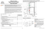
1
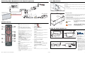
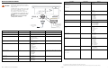
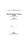
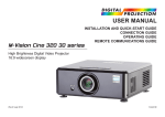
Connecting Sources to the Projector
XtremeProjection™ Series Model X-200i
Active 3D Home Theater Projector
HDMI
Component Video
Quick Setup Guide
SOURCE
SOURC
POWER
POWER
POWER
ISSUE
ISSUE
POWER
LED STA
STATUS
TATUS
LED STA
STATUS
TATUS
USB
SOURCE
COMPONENT 1
RS-232
WIRED REMOTE
POWER
POWER
POWER
I
II
12V TRIGGER
POWER
LED STA
STATUS
TATUS
12V TRIGGER
LED STA
STATUS
TATUS
Pb
Pr
Pb
Pr
Y
WIRED REMOTE
WIRED REMOTE
RGB
RGB
Y
HDMI 2
3D SYNC
HDMI 1
3D SYNC
33
6
Connect 12-volt trigger output to retractable screen or other, +12V trigger-activated equipment
(optional)
34
7
Connect the Active 3D Emitter to the projector
35
8
Apply power to the projector
35
9
Primary lens adjustments: projected image size (zoom), position (shift) and focus
19, 37
10
Change the OSD Language (optional)
38
11
For rear-screen and/or ceiling-mount installations, select the proper picture orientation
39
12
Install and adjust secondary anamorphic lens (optional)
39
52
13
Projector calibration: adjust the following for each input; save settings when finished:
• Aspect ratio
• Brightness
• Contrast
• Color level
• Tint
• Input position
14
Prepare Active 3D Glasses for use and test with 3D source material
73
R
A
IN
RCA-to-BNC
adapter
IM
POWER
LED STA
STATUS
TATUS
LED STA
STATUS
TATUS
WIRED REMOTE
RS-232
COMPONENT
VIDEO OUT
COMPONENT 1
USB
BD/DVD
Y
PB
PR
DTV-Set-Top Box
(DTV-STB)
WIRED REMOTE
RS-232
I
II
12V TRIGGER
12V TRIGGER
RGB
Y
RGB
Y
HDMI 2
Pb
Pr
Pb
HDMI 2
HDMI 1
Pr
HDMI 1
SYNC
3D SY
COMPONENT 2
RGB Camcorder
Computer
Runco X-200i Series Quick Setup Guide
Pr
EL
Connect external controller to RS-232 port; connect IR repeater system to wired remote input
(optional)
ISSUE
PR
5
POWER
USB
30
RGB Video
COMPONENT 1
Connect signal sources to the X-200i
Pb
COMPONENT 2
HDMI source
(BD, DVD, DTV Set-Top Box etc.)
ISSUE
4
HDMI 1
28
HDMI 2
Mount the projector
RGB
3
Y
23
Y
Pb
Install CineWide lens mounting assembly (stationary base plate or AutoScope lens motor – optional)
RGB
COMPONENT 2
For Details, Refer to This Page
in the X-200i Series Installation/
Operation Manual
2
HDMI 2
Pr
Installation Overview
16
HDMI 1
Y
12V TRIGGER
HDMI
AV OUT
Do not tilt your head while using the 3D glasses.
Choose a location for the projector
COMPONENT 1
I
II
12V TRIGGER
3D SYNC
1
USB
COMPONENT 2
The glasses that accompany this product are not safe to use as sunglasses, protective eyewear or any use outdoors or
other than only in conjunction with the proper operation of the Runco product with which they are sold. It is common to dim
the lights in a home theater. Using 3D glasses and the immersive imagery of stereoscopic imagery can increase the risk of
tripping or falling the dark. Special care should be taken.
Procedure
RS-232
RS-232
HDMI 2
USB
HDMI 1
COMPONENT 1
3D SYNC
The quality and appropriateness of the 3D screen materials onto which the image is projected and the quality of the 3D
content being displayed both have a significant and noticeable impact on the overall 3D experience. A properly-calibrated
projection system, including glasses and an optimized third-party screen, displaying high-quality 3D content is the best
formula for immersive and comfortable 3D experiences. Please refer to the X-200i Series Installation/Operation Manual
for proper projector installation and usage instructions.
Step
ISSUE
ISSUE
It is widely recognized that stereographic display devices can cause discomfort, including, without limitation, dizziness,
nausea, headaches, eye fatigue and eye-strain, in some individuals. The 3D effect and experience will vary by individual,
depending on a variety of factors, including his or her health and vision. Runco recommends that users take regular breaks
when watching 3D video or playing games using stereoscopic displays. Discontinue use if any discomfort occurs. Parents
of young children should ensure their children avoid extensive exposure to electronic stereographic entertainment.
PR
EL
IM
IN
A
R
Y
RS-232
USB
WIRED REMOTE
COMPONENT 1
IMPORTANT HEALTH AND SAFETY INFORMATION FOR 3D VIEWING: Please read and make sure you
understand the following safety information before using the product for viewing 3D content. Provide this
information to the end users of this product and ensure that they understand it.
SOURC
WARNING
or
Page 1
020-1201-00 Rev. A (September 2012)
Connecting Other Equipment to the Projector (optional)
Lens Adjustments
AutoScope Lens Motor
Focus
To focus the projected image, grasp the lens by the front ring and rotate it.
Remote Control
IR Sensor
Power
Switch
Focus
AC Input
Zoom
To make the picture smaller (zoom out) or larger (zoom in), slide the zoom control in the direction
shown at left.
Zoom In
IR Repeater
To lock the position of the lens, tighten the knob with a flat-blade screwdriver.
Zoom Out
(3.5-mm, mini
phono plugs)
RS-232
USB
COMPONENT 1
Vertical
Lens Shift
Control
RS-232
USB
WIRED REMOTE
I
II
12V TRIGGER
12V TRIGGER
RGB
Y
RGB
Y
Horizontal Lens Shift
To shift the projected image horizontally, first ensure that the lens lock is not engaged. Insert the
provided hex wrench into the horizontal lens shift adjuster at the top of the projector. Then, turn the
wrench to shift the lens in the desired direction.
Pb
COMPONENT 2
3D SYNC IN
IN
COMPONENT 2
HDMI 2
Pb
HDMI 1
(3-pin mini-DIN plug)
R
POWER
LED STA
STATUS
TATUS
WIRED REMOTE
Y
ISSUE
Active 3D Emitter
LED STA
STATUS
TATUS
HDMI 2
HDMI 1
3D SYNC
Vertical Lens Shift
To shift the projected image vertically, first ensure that the lens lock is not engaged. Insert the
provided hex wrench into the vertical lens shift adjuster on the side of the projector. Then, turn the
wrench to shift the lens in the desired direction.
ISSUE
PR
EL
IM
IN
A
R
Y
POWER
Tip = +12V
A
Sleeve = Ground
COMPONENT 1
Retractable Screen or other
12-volt trigger-activated
device
Caution
3D SYNC
8.
Contrast
Press to adjust white level.
2.
OFF
Use this button to turn the projector off.
9.
Brightness
Press to adjust black level.
3.
Discrete Aspect Ratio Selection Buttons
Press one of these buttons to select an aspect
ratio:
10. Memory Preset Buttons:
16 : 9: For viewing 16:9 DVDs or HDTV programs
in their native aspect ratio.
4 : 3: Scales the input signal to fit 4:3 sources in
the center of the screen.
LETBOX (Letterbox): For viewing nonanamorphic (“full-screen”) DVDs on a 16:9 screen.
V-WIDE (VirtualWide): Enlarges a 4:3 image
horizontally in a non-linear fashion to fit a 16:9 full
screen display.
CINEMA: For viewing 2.35:1 source material.
V-CINE (Virtual Cinema): For viewing 16:9
source material on a 2.35:1 screen.
4
5
7
6
8
9
11
4.
Cursor Keys ( , , , )
Use these buttons to select items or settings,
adjust settings or switch display patterns.
12
ENTER
Press to select a highlighted menu item or confirm
a changed setting.
10
5.
Runco X-200i Series Quick Setup Guide
MENU
Press this button to show or hide the OSD
controls.
6.
Aspect Ratio Selection Button
Press this button repeatedly to select an aspect
ratio.
7.
Source Selection Buttons (1-5):
Press to select a video source. These buttons are
assigned as follows: 1 = HDMI 1;
2 = HDMI 2; 3 = Component 1; 4 = Component 2;
5 = RGB.
WARNING
EL
3
2
ON
Use this button to turn the projector on.
Horizontal
Lens Shift
Control
THE LENS SHIFT MECHANISM CAN BE DAMAGED BY
EXCESSIVE FORCE. Do not attempt to move the primary lens beyond
its normal adjustment range.
Using the Active 3D Glasses
ISF NIGHT
Press to recall settings for the current input from
the “ISF Night” memory preset.
PR
1
1.
IM
Remote Control
Do not attempt any lens adjustments when the lens lock is
engaged. Doing so may cause damage to the zoom or lens shift
mechanisms.
ISF DAY
Press to recall settings for the current input from
the “ISF Day” memory preset.
CUST 1
Press to recall settings for the current input from
the “Custom 1” memory preset.
Battery Status
LED (Red/Blue)
Power Button
CUST 2
Press to recall settings for the current input from
the “Custom 2” memory preset.
Power
Input
• Battery Status LED
Indicates battery charge state when glasses are turned on, as
follows:
= Fully Charged (12 - 15 hrs. left)
= 50% Charged (approx. 4 hrs. left)
= 30% Charged (approx. 2 hrs. left)
= ≤10% Charged (must charge glasses
before further use)
• Power Button
Press to turn the glasses on or off.
• Power Input
To chazrge the glasses, connect this input to your PC or other
USB power source, using the included charging cable.
11. 3D Mode Selection Buttons:
3D AUTO
Press to set the 3D Mode to Auto.
Charging the 3D Glasses
The glasses must be fully charged before first use and whenever
the Battery Status LED flashes red once every couple of
seconds. Charging takes approximately five hours.
3D SBS (Side-by-Side)
Press to set the 3D Mode to 3D Side-by-Side.
3D TAB (Top-and-Bottom)
Press to set the 3D Mode to 3D Top-andBottom.
12. LIGHT
Press momentarily to activate remote backlighting.
Page 2
1.
Attach one end of the supplied charging cable to the Power
Input above the left lens on the glasses.
2.
Attach the other end of the cable to any USB “A” port on a
USB hub, personal computer or display device. The Battery
Status LED lights solid red while the battery is charging.
3.
When the Battery Status LED lights solid blue, the battery is
fully charged. You can disconnect the glasses from the
power source.
020-1201-00 Rev. A (September 2012)
OSD Menu Tree
Note: Default settings appear in bold type.
Menu Display Time
Noise Reduction
Color Space
Gamma
Color Temperature
Color Gamut
SatCo
Adaptive Contrast
DLP Frame Rate
RGB Adjust
Fine Sync
PCE
Runco X-200i Series Quick Setup Guide
(press ENTER to execute)
HDMI CEC
On or Off
Active Source
Signal Format
Pixel Clock
Refresh Rate
Lamp Hours
(read-only)
Logo Display
Altitude
Power On Chime
Frame Locking
0 ... 100 ... 200
Trigger 1
Trigger 2
CineWide
0 ... 200
Auto, REC709, REC601, RGB-PC or
RGB-Video
2.5, 2.35, 2.2, 2.0 or 1.8
5500K, 6500K, 7500K, 9300K or Native
Auto, REC709, SMPTE-C, EBU, Native
or PCE
On or Off
On or Off
Auto, 48 Hz, 50 Hz or 60 Hz
Red / Green / Blue Offset
Red / Green / Blue Gain
V. Position
H. Position
Phase
Tracking
Sync Level
Hue
Saturation
Level
White Balance
Blue Only
Model Name
Serial Number
Software Version
FPGA Version
Reset Everything?
(Yes or No)
On or Off
Test Patterns
On or Off
System Information
Factory Reset
Page 3
Y
Auto Source
Infrared Remote
Front Tabletop, Front
Ceiling, Rear Tabletop
or Rear Ceiling
On or Off
Auto or High
On or Off
On or Off
AutoScope, Lamp, 4:3,
or RS-232
AutoScope, Lamp, 4:3,
or RS-232
Off, CineWide or
AutoScope
On or Off
Normal, Code 2 or Off
Projection Mode
IM
Brightness
Contrast
Color
Tint
Sharpness
On or Off
EL
Resync
Message Boxes
Black, Blue or White
Blank Screen
Auto Power Off
Auto Power On
PR
Input Select
Menu Position
Menu Transparency
PR
EL
IM
IN
A
R
Y
3D Control
Menu Settings
R
Overscan
Language
English, Français, Deutsch, Italiano,
Español, Svenska,
(Simplified
Chinese),
(Traditional Chinese),
Português,
(Russian),
(Japanese) or
(Korean)
Top Left, Top Right, Bottom Left,
Bottom Right or Center
0% (opaque), 25%, 50% or 75%
Forever, 10 Seconds, 30 Seconds or
60 Seconds
On or Off
A
Memory
16:9, Letterbox, 4:3, VirtualWide,
Cinema or Virtual Cinema
Recall Memory
Save Memory
Save ISF
Off, Crop or Zoom
3D Mode
Enable DLP Link
L-R Swap
Dark Time
Sync Delay
1080p24 Output
3D Test Pattern
HDMI 1, HDMI 2, Comp. 1, Comp. 2 or
RGB
IN
Aspect Ratio
(read-only)
020-1201-00 Rev. A (September 2012)
Connect your control system or PC to the
RS-232 input of the projector as shown in the
diagram at right.
Configure the RS-232 controller or PC serial
port as follows: 9,600 bps, no parity, 8 data
bits, 1 stop bit and no flow control.
SOURCE
SOURCE
POWER
POWER
The following is a partial list of supported
serial commands. For a complete list, refer to
the X-200i Series Installation/Operation
Manual.
POWER
WIRED REMOTE
WIRED REMOTE
USB
aspect
overscan
= ?
0 = Off
1 = Crop
2 = Zoom
COMPONENT 1
input
= ?
0 = HDMI 1
1 = HDMI 2
2 = RGB
3 = YPrPb 1
4 = YPrPb 2
3
8
6
resync
(execute)
proj.mode
= ?
trig1
trig2
= ?
2 Receive Data
3 Transmit Data
(from ctrl. system)
5 Ground
IM
(none of the other pins are used)
Notes
Power on command
(execute)
Power off command
osd.timer
0 = Auto
1 = Side-by-side
2 = Top-and-bottom
3 = Off
0 = Normal
1 = Reversed Eyes
= ?
0 = 16:9
1 = Letterbox
2 = 4:3
3 = VirtualWide
4 = Cinema
5 = Virtual Cinema
recall.mem
= ?
0 = Custom 1
1 = Custom 2
2 = ISF Day
3 = ISF Night
4 = Default
save.mem
=
0 = Custom 1
1 = Custom 2
save.isf
=
0 = ISF Day
1 = ISF Night
IN
(to ctrl. system)
(execute)
= ?
0 = Front Tabletop
1 = Front Ceiling
2 = Rear Tabletop
3 = Rear Ceiling
language
? only returns a value if ISF Day or ISF
Night is active, otherwise it returns NA
EL
Values
1
2
7
= ?
Image menu settings.
R
4
9
Notes
A
5
PR
3d.chswap
Commands
= ?
0 - 200
II
PR
EL
IM
IN
A
R
Y
I
RS-232
RS-232
3d.mode
= ?
LED STA
STATUS
TATUS
USB
powoff
brightness
contrast
saturation
hue
sharpness
nr
LED STA
STATUS
TATUS
powon
Values
ISSUE
to Automation/
Control System
or PC
Operation
Commands
ISSUE
All commands must be followed by a
carriage return character.
POWER
COMPONENT 1
WARNING
Operation
Y
Serial Communications
0 = Lamp
3 = 4:3
4 = AutoScope
5 = RS232
6 = On
7 = Off
0 = forever
1 = 10 sec.
2 = 30 sec.
3 = 60 sec.
= ?
0 = English
1 = French
2 = German
3 = Italian
4 = Spanish
5 = Swedish
10= Portuguese
11 = Russian
cinewide
= ?
0 = Off
1 = CineWide
2 = AutoScope
cal.text1
cal.text2
cal.text3
=
Up to 30 characters.
OSD language only
The X-200i start-up screen is customizable with three lines of text of up to 30
characters each. This text appears
below the “CALIBRATED FOR:” text in
the logo screen. The allowable characters are all numbers, letters (uppercase
and lowercase), spaces, and symbols
available in the ASCII code set.
© Copyright 2012 Runco International. All rights are reserved.
Trademarks and registered trademarks used in this document are the property of their respective owners.
Runco X-200i Series Quick Setup Guide
Page 4
020-1201-00 Rev. A (September 2012)