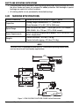
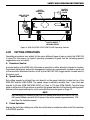
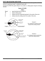
1
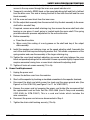
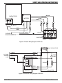
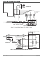
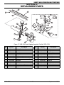
VCM-200 SERIES
Portable Flame
Cutting Machine
SAFETY AND OPERATING
INSTRUCTIONS
Revision: A
Issue Date: September 17, 2008
Manual No: 0056-1351
WE APPRECIATE YOUR BUSINESS!
Congratulations on your new Victor® product. We are proud to
have you as our customer and will strive to provide you with the
best service and reliability in the industry. This product is backed
by our extensive warranty and world-wide service network. To
locate your nearest distributor or service agency, please contact
a representative at the address and phone number in your area
listed on the back cover of this guide, or visit us on the web at
www.victorequip.com.
This Operating Manual has been designed to instruct you on the
correct use and operation of your Victor® product. Your satisfaction
with this product and its safe operation is our ultimate concern.
Therefore, please take the time to read the entire manual, especially
the Safety Precautions. They will help you to avoid potential hazards
that may exist when working with this product.
YOU ARE IN GOOD COMPANY!
The Brand of Choice for Contractors and Fabricators
Worldwide.
Victor® is a Global Brand of Gas Products for Thermadyne Industries
Inc. We manufacture and supply to major welding industry
sectors worldwide including; Manufacturing, Construction, Mining,
Automotive, Aerospace, Engineering, Rural and DIY/Hobbyist.
We distinguish ourselves from our competition through marketleading, dependable products that have stood the test of time. We
pride ourselves on technical innovation, competitive prices, excellent
delivery, superior customer service and technical support, together
with excellence in sales and marketing expertise.
Above all, we are committed to develop technologically advanced
products to achieve a safer working environment within the welding
industry.
WARNINGS
Read and understand this entire Manual and your employer’s safety practices
before installing, operating, or servicing the equipment. While the information
contained in this Manual represents the Manufacturer’s judgment, the Manufacturer
assumes no liability for its use.
VCM-200 Series Portable Flame Cutting Machine
Safety and Operating Instructions
Instruction Guide Number: 0056-1351
Published by:
Thermadyne® Industries, Inc.
2800 Airport Rd.
Denton, TX 76208
(940) 566-2000
www.victorequip.com
U.S. Customer Care: (800) 426-1888
International Customer Care: (905) 827-9777
Copyright © 2008 Thermadyne Industries, Inc. All rights reserved.
Reproduction of this work, in whole or in part, without written permission of the publisher is
prohibited.
The publisher does not assume and hereby disclaims any liability to any party for any loss
or damage caused by any error or omission in this Manual, whether such error results from
negligence, accident, or any other cause.
Publication Date: September 17, 2008
Record the following information for Warranty purposes:
Where Purchased:
Purchase Date:
Equipment Serial #:
ii
Table of Contents
Section 1: Introduction...............................................................................1-1
1.01 How to Use this Manual..............................................1-1
1.02 Receipt of Equipment..................................................1-1
1.03 Description..................................................................1-1
Section 2: Safety Precautions .................................................................2-3
section 3: features and specifications...................................................3-5
3.01 Machine Features........................................................3-5
3.02 Machine Specifications................................................3-6
SECTION 4: MACHINE OPERATION....................................................................4-7
4.01 Torch Setup.................................................................4-7
4.02 Cutting Operations......................................................4-9
SECTION 5: MACHINE MAINTENANCE.............................................................5-13
5.01 Routine Inspection....................................................5-13
5.02 Routine Lubrication...................................................5-14
5.03 Troubleshooting........................................................5-15
5.04 Drive Clutch Adjustment............................................5-16
5.05 Cutting Machine Repair.............................................5-17
section 6: replacement parts.................................................................6-23
SECTION 7: EXPORT MODEL INFORMATION....................................................7-33
Section 8: Statement of Warranty.........................................................8-35
iii
Safety and Operating Instructions
Section 1:
Introduction
1.01 How to Use this Manual
To ensure safe operation, read the entire manual, including the chapters on safety
instructions and warnings.
Throughout this manual, the words WARNING, CAUTION, and NOTE may appear. Pay
particular attention to the information provided under these headings. These special
annotations are easily recognized as follows:
NOTE
NOTE conveys installation, operation, or maintenance information which is
important but not hazard-related.
CAUTION
CAUTION indicates a potentially hazardous situation which, if not avoided, may
result in injury.
WARNING
WARNING indicates a potentially hazardous situation which, if not avoided, could
result in death or serious injury.
1.02 Receipt of Equipment
When you receive the equipment, check it against the invoice to make sure it is complete
and inspect the equipment for possible damage due to shipping. If there is any damage,
notify the carrier immediately to file a claim. Furnish complete information concerning
damage claims or shipping errors to the location in your area, listed on the back cover of
this manual. Include a full description of the parts in error.
If you want additional or replacement copies of this manual, please contact Thermadyne at
(800) 426-1888. Include the Manual number (Page i).
1.03 Description
The VCM-200, VCM-200HT (Hi-Temp.) and VCM-200HS (High Speed) Portable Flame Cutting
Machines have many outstanding design and construction features to give dependable, troublefree operation. A constant speed AC induction motor is located on the side opposite the cutting
torch for cooler operation. The cone disk drive has an automatic wear adjusting mechanism
that prolongs the life of the disk drive. Design simplicity makes the VCM-200 extremely easy
to service. Downtime and repair costs are reduced to a minimum.
0056-1351
1-1
Introduction
safety and operating instructions
All Victor VCM-200 Series portable cutting machines are carefully assembled and thoroughly
tested at the factory before shipment. The machine is designed to provide dependable,
trouble-free service with minimum maintenance. This manual contains information needed to
operate and maintain the machine properly. If additional information is required, contact your
Authorized Victor Distributor.
The VCM-200 is a tough, ruggedly constructed cutting machine, yet compact and light enough
that it may be taken to the work site, wherever it may be. It is a versatile, economic, basic
guidance system that can be used for oxy-fuel flame cutting, flame treating or hardening, MIG
and TIG welding, high-speed plasma arc cutting, or movement of special equipment setups. It
is suitable for field jobs and repair work, plus straight line and circle cutting operations required
in metal fabrication.
The complete VCM-200 cutting machine consists of a heavy duty tractor unit fitted with an
adjustable torch mount and a three-hose gas manifold block. The torch holder has a 32-pitch
pinion to accommodate a variety of cutting torches available for use with the machine. Large
knobs are provided for easy torch position adjustments on both the cross rack holder and the
cutting torch holder.
The VCM-200 cutting machine accessories include a six-foot track section for straight line
cutting, a radius rod assembly for circle cutting operations, a dual torch mount assembly, a
torch holder slide assembly and a heat shield. The dual torch mount assembly provides an
adjustable mount for up to four cutting torches. The torch holder slide assembly is used to
install additional torches on the cross racks of either standard or dual torch mounts. Additional
six-foot track sections are available for extending the VCM-200 operating track to any length
desired. The VCM-200 is listed with Underwriters Laboratories, Inc (UL).
Introduction
1-2
0056-1351
Safety and Operating Instructions
Section 2:
Safety Precautions
Read and understand these operating instructions before attempting to operate or service
this equipment.
The information contained in this document is subject to change without notice.
Warning
This product contains chemicals, including lead, or otherwise produces
chemicals known to the State of California to cause cancer, birth defects and
other reproductive harm. Wash hands after handling.
(California Health & Safety Code § 25249.5 et seq.)
WARNING
Personal injury or property damage can occur if you fail to follow the instructions
in this manual.
WARNING
Working with high-pressure gas can be hazardous. Open all valves SLOWLY. Very
high temperatures and pressures, with possible damage to the equipment, will
result if valves are not opened slowly.
WARNING
DO NOT use a flame or “sniff” test for leaks.
WARNING
Never permit oil, grease, or other combustible materials to come in contact with
cylinders, manifold, and connections. Oil and grease may react with explosive force
while in contact with some gases, particularly oxygen and nitrous oxide.
WARNING
ALWAYS open cylinder, header, and manifold valves very slowly. When valves are
opened rapidly, sudden pressurization will cause heat of recompression to occur.
These temperatures and pressures can damage the manifold system and may
cause injury to operator. ALWAYS open valves slowly.
0056-1351
2-3
Safety Precautions
safety and operating instructions
WARNING
DO NOT kink, twist, or bend pigtails into a radius smaller than 5 inches. If you do
this, the pigtail might burst.
WARNING
ALWAYS secure cylinders with racks, straps, or chains. Unrestrained cylinders
may fall over and damage or break off the cylinder valve.
WARNING
Electrically ground oxygen and fuel gas manifolds and cylinders. Static discharges
and lightning may ignite materials in an oxygen atmosphere, creating fire or
explosions.
WARNING
DO NOT apply heat to any part of the manifold system.
WARNING
DO NOT weld near piping. Excessive heat may cause certain gases to dissociate,
creating explosive force.
Safety Precautions
2-4
0056-1351
Safety and Operating Instructions
section 3:
features and specifications
3.01 Machine Features
The VCM-200 Series cutting machine offers the following operation, performance and
design features.
1.Operating Features
• Makes straight-line cuts of any length.
• Makes circle cuts up to 96" in diameter.
• Makes bevel or chamfer cuts - has calibrated scale for easy torch angle selection.
• Makes X, Y, V or K cuts with multiple torches for plate edge operation.
• Cuts strips, with two or more torches, in a single pass. Infinitely variable cutting speeds
from 1" to 60" per minute (VCM-200/VCM-200HT) or 5" to 120" per minute (VCM-200HS).
• Speed indicator is calibrated at the factory to indicate speed over the entire
speed range.
• Dual speed and clutch controls make the machine easy to operate from either end.
• Routine maintenance is quickly and easily accomplished.
WARNING
The VCM-200 is not designed to detect the end of its track or workpiece. Be sure
an unattended machine does not fall from an elevated work piece.
2. Performance Features
• Constant speed AC induction motor located on the side opposite the cutting torch runs
cooler, so the drive speed is not adversely affected by temperature, as are electronicallycontrolled motors.
• Speed regulation operates well at low and high speeds due to the cone disk variable
speed drive and the AC induction motor.
• Flat top mounting surface has standard bolt pattern to accommodate MIG, TIG, plasma
or other welding or cutting equipment.
• Location of the special rotating manifold ensures easy cutting in either direction and
aids in machine balance and stabilization.
3. Design Features
• Integral carrying handle, lightweight and balanced design allow the machine to be
carried with one hand.
• A balanced design makes the machine stable when cutting, allowing a racking distance of
up to 18" from the machine with a standard torch, and no counterweight is required.
0056-1351
3-5
Features and Specifications
safety and operating instructions
• Cone disk drive has an automatic wear adjusting mechanism which prolongs the life of
the drive. Knobs and levers are recessed for added protection. Ball bearings or special
bushings are used at all critical locations.
• All rotating shafts run on permanently lubricated bearings.
3.02 Machine Specifications
Outline Dimensions
Outline dimensions are shown in Figure 1, below.
Capacities
Cutting Length: Increments of 72" (1829 mm)
Circle Diameter: 4" to 96" (102 to 2438 mm)
Speed Range
VCM-200 and VCM-200HT: 1 to 60 ipm (25 to 1524 mmpm)
VCM-200HS: 5 to 120 ipm (127 to 3048 mmpm)
Power Requirements
115 V .42 A 60 Hz, single phase E Models; 220 V .23A 50 Hz/.21A
60 Hz, single phase
Weights
Tractor Unit alone: 30.5 lbs (13.8 Kg)
Tractor Unit with rigging: 37.5 Ibs (17.0 Kg)
NOTE
The VCM-200HT is modified to withstand 300°F continuous operating temperatures
such as found in mill and foundry applications.
28.5"
724 mm
LOW
DRIVE
HIGH
FREE
5.5"
140 mm
11"
279 mm
11.5"
292 mm
14.25"
362 mm
Figure 1: VCM-200/VCM-200HT/VCM-200HS Outline Dimensions
Features and Specifications
3-6
0056-1351
Safety and Operating Instructions
SECTION 4:
MACHINE OPERATION
The information in this section is provided to familiarize the operator with operating controls
and procedures.
NOTE
Other recommended operating instructions available at your distributor are:
0056-1625 - Safety & Operating Instructions for Compressed Gas Regulators;
0056-0136 - Safety & Operating Instructions for Cutting Torches.
4.01Torch Setup
A. Standard Single Torch Setup
Setup of the VCM-200 with standard torch mount and manifold block is shown in Figure 2.
6
7
5
2
1
3
4
Figure 2:
Setup with Standard Torch Mount
0056-1351
Secure the single torch mount post (1) the outer
case mounting surface with four allen-head cap
screws. Slip the rack handle assembly (2) over the
torch mount post and secure it with the set screw.
The rack handle assembly is free to rotate until
the clamping bolt is tightened. Insert racking bar
assembly (3) so that the rack properly engages
the pinion gear in the rack handle assembly.
Connect the torch holder assembly (4) to the
torch pivot knuckle (5) which fits over the round
end of the racking bar assembly. Leave clamping
screws, provided at each of these points, slightly
loose for adjustment. Then, tighten securely after
positioning adjustments are made.
Insert the cutting torch (6) into the torch holder so
that the torch rack properly engages the adjusting
gear of the torch holder. Tighten the torch holder
wing nuts enough to hold the torch securely, yet
permit vertical adjustment of the torch in the torch
holder with the adjusting knob. Use either twohose or three-hose torches.
Insert the manifold block (7) in the end of the rack
handle assembly. Screw the proper hose adapters
into the inlets and outlets of the manifold block.
Use fuel gas hose adapters in the center pair of
holes and oxygen hose adapters in the outer two
pairs of holes. Connect the required hoses from
the manifold block to the cutting torch. If using a
two-hose cutting torch, omit the right-hand hose.
4-7
Machine Operation
safety and operating instructions
5
4
2
4
3
1
Figure 3: Setup with Dual Torch Mount
B.Optional Dual Torch Setup
Set up the optional dual torch mount assembly, Part No. 0252-0136, as shown in Figure 3.
Install the dual torch mount plate (1) on the machine housing in place of the single torch mount
post supplied with the standard machine package. Attach the removed single torch mount post,
along with the second one (supplied with the dual torch mount assembly), at the ends of the
dual torch mount plate.
Install the rack handle assembly (2) (supplied with the dual torch mount assembly) on one
of the torch mount posts and install the rack handle assembly from the single torch mount
assembly on the other torch mount post (3). Then install the two torch holders (4) on their
respective racking bar assemblies and torches as explained in Section 4.01. Use the Y-fittings
(5) furnished with the dual torch mount assembly to make the necessary dual connections at
the gas manifold accommodate the additional cutting torch.
Machine Operation
4-8
0056-1351
Safety and Operating Instructions
FWD-OFF-REV
SWITCH
REV
CLUTCH
CONTROL
LEVER
SPEED
ADJUSTING
KNOB
LOW
DRIVE
HIGH
FREE
CASTER WHEEL
LOCKING KNOBS
Figure 4: VCM-200/VCM-200HT/VCM-200HS Operating Controls
4.02Cutting Operations
Operating procedures vary widely for the many different types of jobs on which the VCM-200
is used. For this reason, no typical operating procedure is given, but the following general
suggestions may be helpful.
A. Directional Control
A unique feature of the VCM-200 is the ease of operation in either direction, forward or reverse.
Dual speed adjustment and clutch engagement controls are conveniently located on each end
of the machine. Machine direction is set by the FWD-OFF-REV toggle switch located next to
the power cord.
B. Speed Control
Set cutting speeds for straight line cuts directly on the speed indicator located on top of the
VCM-200 and the VCM-200HS. The speed range is infinitely variable from 1 ipm (inch per
minute) to 60 ipm (VCM-200/VCM-200HT) or 5 ipm to 120 ipm (VCM-200HS). Turn the large
knob on either end of the machine to position the speed indicator to the desired cutting speed.
Determine the speed settings for circle cuts with the formula given on Page 12.
NOTE
Use the export (E) models of the VCM-200 Series with either 50 Hz or 60 Hz, 220
VAC power. When used with 50 Hz power, the actual speed is approximately 12%
less than the indicated speed.
C.Clutch Operation
Engage the clutch by rotating one of the two clutch levers, located on either end of the machine,
to the DRIVE position.
0056-1351
4-9
Machine Operation
safety and operating instructions
Place the clutch lever in the FREE position to permit easy manual positioning of the machine
prior to or after the actual cutting operation.
D.Torch Adjustment
The VCM-200 racking assembly provides full adjustment for the torch. The rack handle assembly
permits the torch holder assembly movement toward or away from the tractor unit. The torch
holder allows the torch vertical positioning. The torch pivot knuckle allows the torch positioning
at any angle from ± 90° in a plane perpendicular to the track. If additional torch clearance is
needed, rotate the torch holder assembly 180˚ for an additional clearance of 2 inches. After
adjusting the torch to the desired position, tighten all clamping screws to prevent the torch
from making any unexpected movements.
E. Straight Line Cutting
warning
The VCM-200 is not designed to detect the end of its track or workpiece. Be sure
an unattended machine does not fall from an elevated workpiece.
Cut straight lines using the following procedure:
1. Place the machine track on the work and line it up before placing the machine on the
track.
Track Accessory Information
Part No.
Description
0212-0018
12-foot track section for line cutting
0212-0019
9-foot track section for line cutting
0212-0005
6-foot track section for line cutting
2. Be sure the track is long enough for the cut to be made. If not, install additional track.
Connect track sections carefully. When properly connected, the machine should travel
smoothly from one track section to the next.
3. Place the machine on the track. Place the clutch lever to the FREE position. Be sure
that the gas hoses and the power line are long enough and free to move with the
machine so that it can complete the cut properly.
4. Move the machine to the approximate point where the cut will start. Set the drive
speed control to the desired cutting speed. Set the FWD-OFF-REV switch to the OFF
position. Plug the power cord into a 115 AC, 60 Hz power outlet.
NOTE
The export (E) model of the VCM-200 Series is equipped with a step-down
transformer which permits operation with 220 VAC, 50 Hz (or 60 Hz) power.
5. Ensure that all clamping screws are properly tightened. Light and properly adjust the
torch. Set the FWD-OFF-REV switch to the desired direction of travel. Set the clutch
lever to the DRIVE position.
6. When the cut is completed, stop the machine and shut off the torch.
Machine Operation
4-10
0056-1351
Safety and Operating Instructions
DRIVE
WHEEL
PATH
PATH OF CUT
RA
DI
US
Figure 5: Circle Cutting Setup
F.Circle Cutting
The radius rod and center point make it possible for the VCM-200/VCM-200HS to cut circles
from 4" to 96" in diameter. Remove the two bolts located over the drive wheels in the outer
case. Position the radius rod assembly on the cutting machine, re-insert the bolts and tighten
securely. Adjust the radius rod assembly to the desired length.
Drill a small pilot hole or punch the center of the circle to be cut. Place the point of the center
point in the center of the circle and adjust the radius rod so that the cutting torch can be properly
positioned. Position the torch between the machine and the center point for small diameter
circles. Position the machine between the torch and the center point for large diameter circles.
Adjust the center point so that the inside driving wheel lifts slightly off the work. Loosen the
caster wheel lock knobs so that the caster wheels pivot freely. The machine is now free to
follow the desired radius.
NOTE
Readjust the cutting torch to its proper cutting position after making the adjustment
to lift the inside driving wheel.
Cutting speeds for circle cuts are not set directly on the VCM-200 speed indicator. The indicator
shows the speed of the drive wheel. The drive wheel moves along the circumference of a larger
or smaller circle than the one being cut by the cutting torch. The following formula provides a
0056-1351
4-11
Machine Operation
safety and operating instructions
simple method of determining the proper speed setting for circle cuts, regardless of whether
the torch is positioned inside or outside the tractor path.
Calculate the VCM-200 speed setting for any radius or cutting speed using the following
formula:
Speed = CS (A/B)
where:
Speed
=
speed indicated on the VCM-200
CS
=
desired cutting speed
A
=
distance from the outside driving wheel to the center of the circle
B
=
distance from the cutting torch to the center of the circle
RADIUS ROD
ASSEMBLY
15"
25
CIRLE TO
BE CUT
"
VCM 200
Example 1:
The cutting torch positioned inside
the path of the cutting machine.
PATH OF OUTSIDE
DRIVING WHEEL
CUTTING
TORCH
RADIUS ROD
ASSEMBLY
CUTTING
TORCH
25"
VCM 200
Machine Operation
35
CIRLE TO
BE CUT
"
PATH OF OUTSIDE
DRIVING WHEEL
4-12
Example 2:
The cutting torch position outside the
path of the cutting machine.
0056-1351
Safety and Operating Instructions
SECTION 5:
MACHINE MAINTENANCE
The Victor VCM-200, VCM-200HT and VCM-200HS cutting machines are designed to operate
over extended periods with minimum maintenance. However, continued satisfactory operation
of the machine depends upon the careful performance of a few simple periodic inspections
and the cleaning procedures outlined in this section. With proper care, problems can usually
be detected and corrected before the result in loss of machine operating time. Troubleshooting
procedures are included to help diagnose and correct problems as they occur and before
serious trouble occurs.
Following the inspection and troubleshooting procedures are the maintenance procedures
necessary for maintaining the machine. These sections are designed to provide an understanding
of the components involved and to supply additional maintenance information which cannot
be noted in detail in the Troubleshooting Chart.
5.01 Routine Inspection
Inspect the machine carefully each day before placing it in operation. Visually inspect the
machine and perform the following steps, which include operating checks of all machine
components. If faults or malfunctions are noted while performing these procedures, refer
to the Troubleshooting Chart on Page 15. and the following maintenance procedures for the
components involved.
1. Wipe off all parts of the machine, rack, torch and all track surfaces.
2. Turn the clutch control lever to the FREE position. Check to see that the machine can
be easily pushed along the track.
3. Set the FWD-OFF-REV toggle switch to the OFF position. Turn the SPEED knob to 1
ipm. Plug the power cord into a 115 V, 60 Hz power outlet.
NOTE
The export (E) model of the VCM-200 Series is equipped with a step-down
transformer which permits operation with 220 VAC, 50 Hz (or 60 Hz) power.
4. Set the FWD-OFF-REV toggle switch to the FWD position. With the clutch lever still in
the FREE position, slowly advance the SPEED knob to 60 ipm (VCM-200) or 120 ipm
(VCM-200HS). The sound level should increase as the knob is advanced. Return the
FWD-OFF-REV toggle switch to the OFF position.
5. Set the clutch lever to the DRIVE position and set the FWD-OFF-REV switch to FWD.
If the clutch engaging mechanism is properly adjusted, the machine should move
along the track at the selected speed. Move the FWD-OFF-REV toggle switch to the
REV position and verify that the machine reverses direction.
6. Check to see that the torch (or torches) can be moved up and down with the adjusting
knob(s) and that the torch holder clamping screws are tight enough to maintain the
0056-1351
5-13
Machine Maintenance
safety and operating instructions
selected torch position. Also, check the torch pivot knuckle to see that it's clamping
screw is properly adjusted. Adjust tension of clamping screws, if required.
7. Check for free movement of the racking assembly in the rack handle by rotating the
rack adjustment knob.
8. Inspect all hoses and the power cord carefully for signs of deterioration or damage.
See that all hose connections to the manifold block and the torch (or torches) are
secure.
9. Inspect power cord for frayed insulation or signs of damage.
10.Inspect all gas connections for leaks.
5.02 Routine Lubrication
The only periodic inspection or maintenance required for the VCM-200, other than the
inspection and maintenance covered in the daily procedures, is the following periodic lubrication
procedure.
1. Redistribute the grease on the gear train and the groove in the clutch dog every 100
hours. It is not necessary to add grease. Remove the outer case cover and the inner
case cover to gain access to the gear train (See Page 17, "Inner Case Removal"). Use
the blade of a small screwdriver or similar object to redistribute the grease.
Warning
Unplug the power cord before performing any maintenance on the machine.
Whenever the bottom cover of the machine is removed, short out the capacitor.
Capacitors hold an electrical charge even after the power has been disconnected.
Touch an insulated screwdriver (plastic or rubber handle) across the capacitor
terminals. DO NOT touch the metal blade of the screwdriver with your fingers.
2. Keep the drive disks and cone free of grease. Clean them by wiping with a cloth
dampened with a solvent that does not leave a residue. Alcohol is not an effective
cleaner.
warning
Use solvents only in well-ventilated areas. Avoid contact with skin or prolonged
exposure to fumes. Read and follow the manufacturer's warning label for the
solvent used.
3. Ball bearings or special bushings are used at all critical locations and require no
greasing.
Machine Maintenance
5-14
0056-1351
Safety and Operating Instructions
5.03Troubleshooting
The Troubleshooting Chart serves as an aid in locating possible troubles that may occur in
operating the machine.
Problem
Motor will not run
Possible Cause
1. No power to machine.
2.
3.
4.
5.
6.
1.
Motor runs, but wheels do
not turn
2.
Motor runs, but will not
reverse
Clutch does not disengage
Clutch does not engage
Machine travel speed not
constant
1.
Corrective Action
1. Check power source and cord;
replace cord if required.
Wire connection is loose.
2. Check all wire connections.
Motor thermal protector is 3. Replace motor.
burned out.
Switch is bad.
4. Replace switch.
Motor has open winding.
5. Replace motor.
Faulty capacitor.
6. Replace capacitor.
Disk Drive slipping because 1. Remove output disk assembly.
output disk shaft is not
Clean and re-grease the shaft with
sliding freely in worm shaft.
a grease containing molybdenum
disulfide, such as EM Lubricants
ME-62 or equivalent.
Gears worn.
2. Check gear train and replace
worn parts.
Faulty capacitor.
1. Replace capacitor.
1. Clutch out of adjustment.
2. Throw-out assembly broken.
3. Grooved pin in clutch yoke
broken or missing.
4. Tabs on yoke not positioned
in groove on clutch dog.
5. Control knobs not in proper
position on shaft.
1. Broken clutch spring.
2. Worn clutch gears.
1. Disks Slipping.
2. End play of speed knobs too
loose.
1. Adjust Clutch. See Page 16
2. Replace part.
3. Replace pin.
4. Reassemble properly.
5. Readjust after checking all of the
above.
1. Replace spring.
2. Replace gears.
1. Clean Disks.
2. Loosen set screws securing
speed knobs. Then snub-up
knobs against spring washer and
retighten set screws.
*See Wiring Diagrams, Figure 8, Figure 11, and Figure 19.
0056-1351
5-15
Machine Maintenance
safety and operating instructions
SPEED
ADJUSTING
SHAFT
CLUTCH
SHAFT
CONE DISK
ASSEMBLY
OUTPUT
DISK
ASSEMBLY
WORM SHAFT
ASSEMBLY
MOTOR
TRANSFER
SHAFT
ASSEMBLY
MOTOR
DISK
ASSEMBLY
REAR
AXLE
DRIVE
GEAR
CLUTCH
YOKE
ASSEMBLY
THROW-OUT
LEVER
CLUTCH
DOG
Figure 6: VCM-200/VCM-200HT/VCM-200HS Internal Assemblies
5.04 Drive Clutch Adjustment
Turn the machine upside down; remove the two casters and the bottom cover to access the
clutch. Operate the clutch a few times by moving the clutch lever from FREE to DRIVE and observe
how the "over-center" action disengages the clutch. With the clutch lever in the DRIVE position,
the end of the lever should have about 1/4-inch movement for ideal freeplay. This is necessary
to assure that the clutch will fully engage and have enough travel for disengagement.
Adjust the clutch freeplay by the following steps:
1. Place the clutch in DRIVE position.
2. Rotate the drive wheels by hand to assure that the clutch teeth are fully engaged.
3. Loosen the screw in the throw-out lever and rotate the throw-out lever until it presses
against the cam on the clutch shaft.
Machine Maintenance
5-16
0056-1351
Safety and Operating Instructions
4. Re-tighten the screw.
5. Freeplay will automatically be obtained; this allows approximately 1/4-inch movement
at the extreme end of the throw-out lever.
1. LOOSEN SCEW
2. PRESS LEVER
DOWN, HOLDING
CLUTCH SHAFT
ASSEMBLY CAM
AGAINST ROLL PIN
3. TIGHTEN SCREW
SCREW
THROW-OUT
LEVER
CLUTCH
YOKE
SHAFT
CLUTCH SHAFT
ASSEMBLY
ROLL PIN
Figure 7: Drive Clutch Adjustment
5.05Cutting Machine Repair
Remove the inner case from the outer case when making major repairs to the cutting machine.
This is not necessary for minor work such as lubrication or clutch adjustment.
A. Inner Case Removal
Perform the following steps:
1. Unplug the power cord.
2. Remove the rack handle assembly.
3. Remove the clutch control levers from each end of the machine.
4. Remove the SPEED knobs from each end of the machine. A flat washer and two (2)
spring washers are provided under each SPEED knob.
5. Remove one end plate, which is held by two button head socket screws.
6. Remove the four socket head cap screws that have their heads counter-bored into
the top of the outer case. These screws secure the inner case.
7. Turn the machine upside down. Loosen the caster locking knobs a few turns to clear
groove in caster, then remove casters.
8. Remove the bottom cover, which is held by six slotted head screws.
0056-1351
5-17
Machine Maintenance
safety and operating instructions
WARNING
Unplug the power cord before performing any maintenance. Whenever the bottom
cover of the machine is removed, short out the capacitor. Capacitors hold an
electrical charge even after the power cord has been disconnected. Touch an
insulated screwdriver (plastic or rubber handle) across the capacitor terminals
under the rubber boot. Hold the screwdriver by the insulated handle.
9. Lift the inner case assembly from the outer case. Place it beside the outer case with
the wires still connected.
10.Remove inner case cover and gasket which are secured by seven slotted head
screws.
11.Reverse procedures for reassembly. When reassembling the SPEED knobs, apply
enough pressure to the SPEED knob to flatten the spring washers and hold while
tightening the set screws.
B. Rear Axle Removal
1. Remove the inner case from the outer case. (See Page 17)
2. Remove the drive wheel and the key from each end of the axle.
3. Remove the retaining ring at the end of the spring. Remove the ring by inserting a
screwdriver under the ring and twist the screwdriver to pry the ring off the axle.
4. Remove the bushing on the end of the axle toward the motor.
5. Slide the axle and spring partway through the bushing hole. Remove the spring and
the two (2) remaining retaining rings.
6. Slide the axle through the bushing hole and out of the clutch dog and drive gear.
7. Reverse this procedure for reassembly.
C.Transfer Shaft Removal
1. Remove the inner case from the outer case. (See Page 17)
2. Remove the capacitor which is held by two screws and a clamp.
3. Remove the retaining ring.
4. Remove the transfer shaft by sliding the entire assembly out of the inner case through
the bearing mounting hole.
Note
The center bearing is captured on the transfer shaft and is not available
separately.
D.Cone Disk,Output Disk and Worm Shaft Removal
1. Remove the inner case from the outer case. (See Page 17)
2. Remove the retaining rings and washers from both ends of the speed adjusting shaft.
Machine Maintenance
5-18
0056-1351
Safety and Operating Instructions
3. Loosen the cone block backlash adjusting cap screw usinga 7/64" hex key. Gain
access to the cap screw through the inner case speed indicator slot.
4. Temporarily, reinstall a SPEED knob on the speed adjusting shaft end that is farthest
from the drive cone. This aids in turning the shaft to free both the shaft and the cone
block assembly.
5. Lift the cone and cone block from the inner case.
6. Pull the output disk assembly from the worm shaft. Key the disk assembly to the worm
shaft with a woodruff key.
7. If required, remove worm shaft retaining ring, then remove the worm shaft and outer
bearing as one piece. A small spring is located inside the worm shaft. This spring
provides automatic pressure adjustment for the entire disk drive.
8. Before reassembly:
a. Clean the drive disks.
b. Wipe a very thin coating of a moly grease on the shaft and key of the output
disk assembly.
9. Install the washers and retaining rings on the speed adjusting shaft. Assemble the
end of the shaft that requires the spring washer first. This allows compression of the
spring washer and ease the assembly of the larger retaining ring.
10.Tighten the cone block backlash adjusting cap screw until play between the cone
block and speed adjusting shaft is minimized. Loosen cap screw slightly if speed knob
requires excessive turning force or cone block rotates with adjusting shaft.
11.Tighten all knob set screws securely (15 in-lb).
E. Power Cord Replacement
1. Unplug the power cord.
2. Remove the bottom cover from the machine.
3. Short out the capacitor by touching an insulated screwdriver to the capacitor terminals.
4. Disconnect the black and white power line leads and the green ground wire (See
Figure 8 or 9 for VCM-200) (see Figure 10 or 11 for VCM-200HT).
5. Remove the power cord by loosening the power cord holder. We recommend that
the replacement cord be Victor Part No. 0252-0058 (Use Hi-Temp cord assembly
0252-0068 for VCM-200HT). This is a cord and holder which includes the
wire connectors.
6. Reconnect the power cord wires as disconnected in Step 4.
7. Tighten the strain relief bushing securely (12in-lb).
0056-1351
5-19
Machine Maintenance
safety and operating instructions
F. Switch Replacement
1. Unplug the power cord.
2. Remove the bottom cover from the machine.
3. Short out the capacitor by touching an insulated screwdriver to the capacitor terminals.
4. Disconnect the five switch leads. Four of these are the red, blue, yellow and
black motor leads. The fifth switch lead is the black line from the power cord.
(See Figure 8)
5. Remove the jam nut on the threaded portion of the switch protruding outside of the
case. Pull the switch inside the case and remove.
6. We recommend that the replacement switch be Victor Part No. 0252-0057 (Use HiTemp switch assembly 0252-0140 for VCM-200HT). This is a pre-wired switch and
includes the wire connectors.
7. Install the new switch by reversing the procedure in step 5.
8. Reconnect the switch as disconnected in Step 4.
G. Motor Replacement
Victor recommends that the motor be replaced as an entire assembly. It includes the motor,
mounting plate, spacer sleeve and drive disk. Purchase the assembly directly from Victor. This
eliminates downtime and assures that the drive disk runs accurately.
1. Remove the inner case from the outer case. (See Page 17)
2. Short out the capacitor by touching an insulated screwdriver to the capacitor
terminals.
3. Remove the rubber boot from the capacitor and disconnectthe two red leads.
4. Disconnect the red, blue, black, yellow and white motor wires leading to the switch.
Note that red is connected to red, blue is connected to blue, etc.
5. Remove the four socket head cap screws that mount the motor plate to the inner
case. Note that the green ground wire from the power cord is secured to the case by
one of the four screws.
6. Loosen the motor disk set screw, if so equipped (optional on keyed motors). Slide the
disk away from the motor to allow motor plate dowels to clear the inner case.
NOTE
If the motor disk is to be re-used, DO NOT pry on back side of the disk. Remove
a tight disk by bending a pry bar to reach behind the disk boss.
7. Remove the motor and drive disk assembly from the inner case.
8. Reverse this procedure for reassembly.
Machine Maintenance
5-20
0056-1351
Safety and Operating Instructions
BLACK
CAPACITOR
YELLOW
MOTOR
BLUE
WHITE
RED
RED
1
WHITE
115 VAC
POWER SUPPLY
BLACK
BLACK
SWITCH
BLACK
YELLOW
BLUE
BOOT
RED
GREEN
WHITE
RED
4
2
5
3
6
BLUE
7
8
9
BLUE
Figure 8: Pictorial Wiring Diagram, VCM-200
WHITE
115 VAC
POWER
LINE
RED
RED
4µF CAPACITOR
WHITE
RED
BLACK
GREEN
4
5
FUSE
LINK
YELLOW
6
1
BLACK
2
8
7
START
3
MAIN
BLUE
9
BLACK
FWD-OFF-REV
SWITCH
AC MOTER
Figure 9: Schematic Wiring Diagram, VCM-200
0056-1351
5-21
Machine Maintenance
safety and operating instructions
BOOT
CAPACITOR
RED
RED
BLACK
YELLOW
TERMINAL
STRIP
BLUE
RED
1
WHITE
115 VAC
POWER SUPPLY
BLACK
YELLOW
RED
BLUE
WHITE
GREEN
MOTOR
4
7
WHITE
2
BLACK
IN-LINE FUSE
(AGC 1A. FAST ACTING)
3
SWITCH
BLUE
5
8
9
6
BLUE
Figure 10: Pictorial Wiring Diagram, VCM-200HT (Hi-Temp)
WHITE
115 VAC
POWER
LINE
RED
RED
4µF CAPACITOR
440V
WHITE
WHITE
RED
BLACK
GREEN
4
5
FUSE
LINK
YELLOW
6
1
BLACK
FUSE AGC 1A.
FAST ACTING
START
2
MAIN
3
7
8
BLUE
9
BLACK
FWD-OFF-REV
SWITCH
AC MOTER
Figure 11: Schematic Wiring Diagram, VCM-200HT (Hi-Temp)
Machine Maintenance
5-22
0056-1351
Safety and Operating Instructions
section 6:
replacement parts
2
1
4
3
28
14
27
15
16
5
7
24
18
6
26
25
17
23
8
9
19
20
21
10
22
11
12
13
Figure 12: VCM-200 Series Rigging Assembly. Part No. 0252-0134
Item
No.
1
2
3
4
5
6
7
8
9
10
11
12
13
14
Part No.
0252-0028
0253-0081
0251-0145
1400-0163
1409-0103
1406-0171
0252-0027
1401-0070
1401-0008
1400-0161
1409-0001
0251-0020
0252-0135
1409-0100
0056-1351
Description
Racking Bar Assembly
Gear Rack
Hex Rod
Screw (3)
Wing Nut
Washer
Rack Handle Pinion Assembly
Set Screw
Set Screw
Bolt (2)
Nut
Handle Post
Torch Holder and Pivot Assembly
Wing Nut
6-23
Item
No.
15
16
17
18
19
20
21
22
23
24
25
26
27
28
Part No.
1406-0171
1400-0160
0254-0036
1400-0166
1401-0070
0251-0042
1406-0171
0252-0037
1409-0103
1400-0161
0251-0038
0251-0037
1406-0080
0251-0051
Description
Washer
Bolt (2)
Angle Scale
Hex Head Bolt
Set Screw
Torch Holder
Washer (2)
Pinion Assembly
Wing Nut
Bolt
Angle Pointer
Torch Pivot Knuckle
Washer
Knob
Replacement Parts
safety and operating instructions
8
2
9
3
1
5
6
4
13
7
16
25
12
14
15
17
19
10
11
26
27
18
28
29
20
21
30
22
23 24
31
32
35
33
34
Figure 13: VCM-200 / VCM-200HT* Series Main Assembly
(*For continuous use at up to 300˚F)
Replacement Parts
6-24
0056-1351
Safety and Operating Instructions
Item No.
1
2
3
4
5
6
7
8
9
10
11
12
13
14
15
16
17
18
19
20
21
22
23
24
25
26
27
28
29
30
31
32
33
34
35
Part No.
0252-0081
1412-0107
1412-0106
0251-0091
0950-0068
0960-0029
0253-0041
1400-0196
0252-0134
1400-0191
0250-0086
0254-0041
0251-0042
0254-0045
1400-0195
0254-0020
0252-0057
0252-0140
1417-0051
0252-0058
0252-0068
0761-0132
0251-0167
1400-0191
1401-0071
0251-0041
0251-0045
0254-0015
1406-0153
1406-0172
0254-0016
1400-0194
0251-0170
0251-0174
0252-0130
0252-0131
0252-0141
1419-0000
1419-0001
0251-0138
1400-0190
0252-0124
0250-0067
Description
Manifold Assembly
Hose-Fuel
Hose-Oxy (2)
Manifold Block
Oxygen Adapter (4)
Fuel Adapter (2)
Manifold Shaft
Screw (4)
Rigging Assembly
Screw (4)
Label Cover (only on VCM-200HT)
Label VCM-200
Label VCM-200HS
Label VCM-200HT
Screw (4)
Switch Legend
Switch VCM-200
Switch VCM-200HT
Dust Protection Assembly
Power Cord VCM-200
Power Cord VCM-200HT
Spring
Caster Locking Knob
Screw (4)
Set Screw (8)
Speed Adjusting Knob (2)
Clutch Lever (2)
End Plate (front)
Washer (2)
Curved Washer (4)
End Plate (rear)
Screw (4)
Outer Case VCM-200
Outer Case VCM-200HT
Inner Case Assembly (VCM-200)
Inner Case Assembly (VCM-200HS)
Inner Case Assembly (VCM-200HT)
Foam Seal (2) VCM-200
Foam Seal (2) VCM-200HT
Caster Bushing (2)
Screw (6)
Caster (2)
Outer Case Cover
note
Item Numbers 29, 17, 15, 14 and 32 can be purchased as the Outer Case Assembly,
Part No. 0252-0116.
0056-1351
6-25
Replacement Parts
51
50
49
48
43 42
24
45
44
38
35
31
4
32
4
6
1
5
34
33
19
36
20
8
7
2
3
9
37
11
12
10
39
13
14
40
23
22
21
15
41
46
17
47
25
16
26
18
30
27
28
53
29
52
54
safety and operating instructions
Figure 14: Inner Case Assembly
VCM-200, Part No. 0252-0130
VCM-200HS, Part No. 0252-0131
VCM-200HT, Part No. 0252-0141
Replacement Parts
6-26
0056-1351
Safety and Operating Instructions
Item No.
1
2
3
4
5
6
7
8
9
10
11
12
13
14
15
16
17
18
19
20
21
22
23
24
25
26
27
28
29
30
31
32
33
34
35
36
37
38
39
40
41
42
43
44
45
46
47
48
49
50
51
52
53
54
0056-1351
Part No.
1406-0156
1406-0170
0320-0148
1406-0170
0253-0101
1404-0103
1404-0060
1400-0200
1406-0117
0252-0132
0252-0142
1417-0040
0251-0120
0252-0129
1400-0190
0254-0010
0250-0060
0254-0009
0250-0061
0252-0073
1404-0105
1406-0153
1406-0172
1406-0143
0255-0040
0255-0050
0252-0060
0252-0065
0251-0159
1416-0031
1406-0119
1401-0069
1406-0144
1406-0154
0253-0026
1400-0194
0251-0046
0253-0006
1404-0096
0252-0133
1406-0172
1416-0053
1406-0145
1400-0190
1408-0050
0252-0122
0251-0160
1406-0152
1400-0207
0251-0060
1404-0100
0251-0168
0320-0121
1416-0032
0252-0053
1406-0118
Description
Spring Washer
Retaining Ring
Spring
Retaining Ring
Rear Axle
Key (2)
Woodruff Key
Screw (4)
Washer (4)
Motor/Disk Assembly VCM-200 / VCM-200HS - SEE DETAIL C
Motor/Disk Assembly VCM-200HT - SEE DETAIL C
Cap Pointer
Speed Indicator
Cone Disk Assembly
Screw (7)
Disk Warning Label
Inner Case Cover
Power Warning Label
Gasket
Clutch Yoke
Pin
Washer
Retaining Ring
Capacitor (VCM-200 / VCM-200HS Only)
Rubber Boot (VCM-200 / VCM-200HS Only)
Transfer Shaft Assembly VCM-200 / VCM-200HT
Transfer Shaft Assembly VCM-200HS
Shaft Collar
Ball Bearing
Retaining Ring
Set Screw (2)
Retaining Ring
Washer
Speed Adjusting Shaft
Screw
Throw-Out Lever
Yoke Shaft
Pin (2)
Clutch Shaft Assembly
Washer
Bushing (2)
Retaining Ring
Screw (2) (VCM-200 / VCM-200HS Only)
Washer (2) (VCM-200 / VCM-200HS Only)
Inner Case - SEE DETAIL B
Drive Wheel (2)
Washer (2)
Screw (2)
Capacitor Strap (VCM-200 / VCM-200HS Only)
Woodruff Key
Output Disk Assembly
Spring
Bearing (2)
Worm Shaft Assembly
Retaining Ring
6-27
Replacement Parts
safety and operating instructions
3
4
2
6
1
8
5
10
7
11
12
9
15
13
14
16
17
Detail A: Cone Disk Assembly, Part No. 0252-0129
1
2
3
5
4
Detail B: Inner Case, Part No. 0252-0122
Replacement Parts
6-28
0056-1351
Safety and Operating Instructions
5
6
1
7
2
3
4
8
10
9
Detail C: Motor Disk Assembly, Part No. 0252-0132 / 0252-0142 VCM-200HT
Detail a
Item No.
1
2
3
4
5
6
7
8
9
Part No.
0251-0162
1406-0121
1406-0141
1416-0031
0251-0163
1406-0141
0253-0102
1416-0031
0251-0102
Description
Cone Disk
Spring Washer
Retaining Ring
Ball Bearning
Spacer
Retaining Ring
Cone Shaft
Ball Bearing
Spacer
Item No.
10
11
12
13
14
15
16
17
Part No.
0250-0066
1400-0193
1401-0071
0251-0169
1401-0072
1409-0056
1401-0008
1400-0206
Description
Cover
Screw (3)
Set Screw
Cone Block
Set Screw
Hex Nut
Set Screw
Cap Screw
detail b
Item No.
1
2
3
4
5
Part No.
1400-0192
1416-0041
Screw
Bushing
Description
1416-0040
Bushing
1416-0042
Bushing
detail c
Item
No.
1
2
3
4
5
Part No.
0250-0085
1400-0192
1404-0104
0251-0172
0252-0054
0252-0064
0056-1351
Item
No.
6
7
8
9
10
Description
Motor Strap
Screw (2)
Dowel Pin (2)
Flange
Motor
Motor VCM-200HT
6-29
Part No.
Description
1404-0100
1401-0018
1400-0192
0251-0158
0251-0112
Woodruff Key
Set Screw (Optional)
Screw (4)
Sleeve
Motor Disk
Replacement Parts
safety and operating instructions
common hardware specifications
Part No.
Description
1400-0151
Screw, Slotted Head, #8-32 UNC-2A x 6/16 Long
1400-0160
Bolt, Hex Head Tap, 5/16-18 UNC-2A x 2.0 Long
1400-0161
Bolt, Hex Head Tap, 5/16-18 UNC-2A x 1-1/2 Long
1400-0163
Screw, Hex Socket Flat Head Cap, #8-32 UNC-2A x 1/2 Long
1400-0165
Screw, Hex Head Cap, 1/4-20 UNC-2A x 1.0 Long
1400-0190
Screw, Slotted Head, #8-32 UNC-2A x 5/16 Long
1400-0191
Screw, Hex Socket Button Head Cap, #8-32 UNC-2A x 1/4 Long
1400-0192
Screw, Hex Socket Flat Head Cap, #10-24 UNC-2A x 3/8 Long
1400-0193
Screw, Hex Socket Flat Head Cap, #4-40 UNC-2A x 1/4 Long
1400-0194
Screw, Hex Socket Flat Head Cap, 1/4-20 UNC-2A x 7/8 Long
1400-0195
Screw, Hex Head Cap, 1/4-20 UNC-2A x 1/2 Long
1400-0196
Screw, Hex Socket Button Head Cap, 1/4-20 UNC-2A x 5/8 Long
1400-0206
Screw, Hex Head Cap, Self Locking, #8-32 UNC-2A x 1/2 Long
1401-0008
Set Screw, Hex Socket Oval Point, 1/4-20 UNC-2A x 3/4 Long
1401-0070
Set Screw, Hex Socket Cup Point, #10-24 UNC-2A x 3/8 Long
1401-0071
Set Screw, Hex Socket Cup Point, #8-32 UNC-2Ax 1/4 Long
1401-0072
Set Screw, Hex Socket Cup Point, 1/4-20 UNC-2A x 3/4 Long
1406-0080
Washer, Bevel, .38 I.D., .75 O.D., .056 Thick
1406-0117
Lock Washer, #10 Split
1406-0152
Washer, SAE Flat, 7/32 I.D., 1/2 O.D., 3/64 Thick
1406-0153
Washer, SAE Flat, 11/32 I.D., 11/16 O.D., 1/16Thick
1406-0154
Washer, SAE Flat, 13/32 I.D., 13/16 O.D.,1/16 Thick
1408-0050
Washer, SAE Flat, #8
1409-0001
Nut, STO Hex 5/16-18 UNC-2B x 1/2 Wide
1409-0042
Nut, Hex Jam, 3/8-16 UNC-2B x 9/16 Wide
1409-0056
Nut, Hex. 1/4-20 UNC-2B
1409-0100
Nut, Wing 5/16-18 UNC-2B
Replacement Parts
6-30
0056-1351
Safety and Operating Instructions
4
3
5
1
6
2
8
7
9
10
11
12
Figure 15:
Radius Rod Assembly (top), Part No. 0252-0040
Heat Shield (bottom), Part No. 0252-0103
Item No.
1
2
3
4
5
6
0056-1351
Part No.
0253-0039
0251-0021
1409-0001
1409-0100
0251-0022
0251-0103
Description
Radius Rod
Mounting Plate
Nut (2)
Wing Nut (2)
Link (2)
Spacer (2)
Item No.
7
8
9
10
11
12
6-31
Part No.
0251-0151
1409-0042
0251-0103
1400-0165
1406-0005
0250-0070
Description
Center Point
Nut
Spacer
Screw (2)
Washer (2)
Heat Shield
Replacement Parts
safety and operating instructions
1
TIGHTEN NUT UNTIL
IT BOTTOMS OUT.
SLEEVING IS TO
BE FLUSH TO 1/8"
EXTRUDED OUT.
2
3
4
5
7
6
8
BEND LEG
TO FIT
10
WHITE
RED
BLACK
BLUE
BLACK
YELLOW
9
GREEN
11
Figure 16: VCM-200HT Outer Case Assembly, Part No. 0252-0116
Item No.
Part No.
Description
1417-0051 Dust Boot
1
0254-0020 Switch Legend
0252-0140 Switch Assembly*
1400-0190 Screw (2)
2
1408-0050 Washer (2)
3
0255-0055 Bracket
0255-0041 Capacitor, Extra Heavy Duty 440V, requires horizontal mount (as shown)
4
0255-0040 Capacitor, Original 370V, vertical mount
5
0255-0050 Boot
6
0255-0044 Fuse (AGC 1A Fast Acting)
7
1400-0211 Screw
8
0255-0042 Terminal Strip
9
0252-0068 Cord Assembly
10
0251-0138 Bushing (2)
11
0251-0174 Outer Case
* Switch Assembly 0252-0140 includes wiring harness, fuse holder and fuse.
note
To prevent a short circuit, make sure that all wire strands are inserted and tightly
clamped in the terminal strip.
Replacement Parts
6-32
0056-1351
Safety and Operating Instructions
SECTION 7:
EXPORT MODEL INFORMATION
3
1
4
2
5
6
7
8
Figure 17: VCM-200E / VCM-200HSE Assembly (Export Only)
Item
No.
1
2
3
4
Part No.
Description
1417-0051
0252-0066
0254-0043
0254-0044
1400-0151
Dust Boot and Nut
Switch
Speed Label, VCM-200E
Speed Label, VCM-200HSE
Screw
Item
No.
5
6
7
8
Part No.
Description
0208-0254
0204-0156
1406-0088
1409-0072
Spacer
Transformer
Lockwasher
Nut
note
VCM-200 and VCM-200E Conversion Kit, Part No. 0252-0139 includes all parts
listed above, except Item No. 2. Also includes instructions, transformer mounting
hole location template and wiring diagram (switch and transformer complete
with wiring connections).
0056-1351
7-33
Export Model Information
safety and operating instructions
STEP-DOWN TRANSFORMER
BLACK
EXPORT
MODELS
ONLY
RED
WHITE
WHITE
CAPACITOR
BLACK
YELLOW
BLUE
MOTOR
BLACK
YELLOW
BLUE
RED
RED
BLACK
WHITE
BOOT
GREEN
RED
BLUE
220 VAC
POWER SUPPLY
YELLOW
RED
BLACK
SWITCH
Figure 18: Pictorial Wiring Diagram, VCM-200E
WHITE
RED
WHITE
RED
RED
FUSE
LINK
RED
4
220 VAC
POWER
LINE
WHITE
RED
4µF CAPACITOR
220V/110V
STEP-DOWN
TRANSFORMER
220VAC
PRIMARY
110 VAC
5
6
SECONDARY
BLACK
BLACK
BLACK 2
BLACK
GREEN
8
YELLOW YELLOW
1
START
3
MAIN
7
9
BLUE
BLUE
BLACK
BLACK
FWD-OFF-REV
SWITCH
AC MOTOR
Figure 19: Schematic Wiring Diagram, VCM-200E / VCM-200HSE
Export Model Information
7-34
0056-1351
Safety and Operating Instructions
Section 8:
Statement of Warranty
LIMITED WARRANTY: THERMADYNE® warrants that its products will be free of defects
in workmanship or material. Should any failure to conform to this warranty appear within
the time period applicable to the THERMADYNE products as stated below, THERMADYNE
shall, upon notification thereof and substantiation that the product has been stored,
installed, operated, and maintained in accordance with THERMADYNE’s specifications,
instructions, recommendations and recognized standard industry practice, and not subject
to misuse, repair, neglect, alteration, or accident, correct such defects by suitable repair
or replacement, at THERMADYNE’s sole option, of any components or parts of the product
determined by THERMADYNE to be defective.
THIS WARRANTY IS EXCLUSIVE AND IS IN LIEU OF ALL OTHER WARRANTIES, EXPRESS OR IMPLIED, INCLUDING ANY WARRANTY OF MERCHANTABILITY OR FITNESS FOR A PARTICULAR PURPOSE.
LIMITATION OF LIABILITY: THERMADYNE shall not under any circumstances be
liable for special or consequential damages, such as, but not limited to, damage or loss
of purchased or replacement goods, or claims of customers of distributor (hereinafter the
“Purchaser”) for service interruption. The remedies of the Purchaser set forth herein are
exclusive and the liability of THERMADYNE with respect to any contract, or anything done in
connection therewith such as the performance or breach thereof, or from the manufacture,
sale, delivery, resale, or use of any goods covered by or furnished by THERMADYNE whether
arising out of contract, negligence, strict tort, or under any warranty, or otherwise, shall not,
except as expressly provided herein, exceed the price of the goods upon which such liability
is based.
THIS WARRANTY BECOMES INVALID IF REPLACEMENT PARTS OR ACCESSORIES ARE USED WHICH MAY IMPAIR THE SAFETY OR PERFORMANCE OF
ANY THERMADYNE PRODUCT.
THIS WARRANTY IS INVALID IF THE PRODUCT IS SOLD BY NON-AUTHORIZED PERSONS.
This warranty is effective for the time stated in the Warranty Schedule beginning on the date
that the authorized distributor delivers the products to the Purchaser.
Warranty repairs or replacement claims under this limited warranty must be submitted by
an authorized THERMADYNE repair facility within thirty (30) days of the repair. No transportation costs of any kind will be paid under this warranty. Transportation charges to send
products to an authorized warranty repair facility shall be the responsibility of the Purchaser.
All returned goods shall be at the Purchaser’s risk and expense. This warranty supersedes
all previous THERMADYNE warranties.
0056-1351
8-35
Statement of Warranty
U.S. Customer Care:
ARCAIR ® / STOODY ® / THERMAL ARC ® / THERMAL DYNAMICS ® / TWECO ® / VICTOR ®................... 800-426-1888
FIREPOWER ® ................. 800-858-4232 / FAX 800-535-0557
TDC AUTOMATION................... 866-279-2628
TURBOTORCH ® ............. 800-238-0282 / FAX 800-535-0557
VICTOR MEDICAL .................... 800-382-8187
VICTOR SPECIALTY PRODUCTS ................... 800-569-0547
/
/
/
/
FAX
FAX
FAX
FAX
800-535-0557
800-535-0557
800-535-0557
800-535-0557
Canada Customer Care: 905-827-4515 / FAX 800-588-1714 • International Customer Care: 905-827-9777 / FAX 905-827-9797
CIGWELD Customer Care: 1300-654-674 / FAX 613+ 9474-7391 • www.thermadyne.com
A Global Cutting & Welding Market Leader™
W O R L D H E A D Q UA R T E R S :
THE AMERICAS
Denton, TX USA
U.S. Customer Care
Ph: (1) 800-426-1888
Fax: (1) 800-535-0557
Miami, FL USA
Sales Office, Latin America
Ph: (1) 954-727-8371
Fax: (1) 954-727-8376
Oakville, Ontario, Canada
Canada Customer Care
Ph: (1) 905-827-4515
Fax: (1) 800-588-1714
International Customer Care
Ph: (1) 905-827-9777
Fax: (1) 905-827-9797
16052 Swingley Ridge Road, Suite 300
EUROPE
ASIA/PACIFIC
Chorley, United Kingdom
Customer Care
Ph: (44) 1257-261755
Fax: (44) 1257-224800
Cikarang, Indonesia
Customer Care
Ph: 62 21+ 8983-0011 / 0012
Fax: 62 21+ 893-6067
Milan, Italy
Customer Care
Ph: (39) 0236546801
Fax: (39) 0236546840
Osaka, Japan
Sales Office
Ph: 816-4809-8411
Fax: 816-4809-8412
© Thermadyne Industries, Inc., 2008
•
Melbourne, Australia
Australia Customer Care
Ph: 1300-654-674
Fax: 613+ 9474-7391
International
Ph: 613+ 9474-7508
Fax: 613+ 9474-7488
St. Louis, Missouri 63017
Rawang, Malaysia
Customer Care
Ph: 603+ 6092-2988
Fax: 603+ 6092-1085
www.thermadyne.com
U. S. A .
Shanghai, China
Sales Office
Ph: 86-21-64072626
Fax: 86-21-64483032
Singapore
Sales Office
Ph: 65+ 6832-8066
Fax: 65+ 6763-5812
Printed in U.S.A.