1
Service
Manual
Carton Clamps and
Appliance Clamp
ManualNumber667451
cascade@
corporation
Cascade is a Registered
P.O. Box 20187
l
Trademark
Portland,
of Cascade Corporation.
Oregon 97220
l
(503) 666-1511
Contents
Page
Number
.6-1
INTRODUCTION, Section 1 ...............
INSTALLATION INSTRUCTIONS, Section 2 . .6-2
.6-2
Truck System Requirements ..............
6-3
Prior to Installation. ......................
6-5
Installation .............................
.6-5
Attachment Stop Blocks. .................
.6-5
Prior to Operation. ......................
.6-6
PERIODIC MAINTENANCE, Section 3 ......
.6-7
TROUBLESHOOTING, Section 4 ...........
.6-7
General Procedures. ....................
.6-9
Plumbing. .............................
.6-17
Checking Truck Output ..................
Clamp Drops Load Only When Sideshifting ... 6-17
General Pressure Test, Carton Clamps with a
.6-18
Conventional Valve Only ...............
General Pressure Test, Appliance Clamps with
.6-20
a Conventional Valve Only. .............
Troubleshooting Tests, Clamps with a Hi-Ball
.6-22
Valve Only. ..........................
.6-24
SERVICE, Section 5 ......................
.6-24
Clamp Removal and Installation ...........
Arms .................................. 6-24
.6-24
Arm Removal and Installation ...........
Arm Disassembly, Service, and Reassembly,
.6-26
Carton Clamps .....................
Arm Disassembly and Reassembly,
.6-26
Appliance Clamp ...................
Sliding Arm Bushing Replacement,
.6-27
Two-piece Style ....................
Sliding Arm Bushing Replacement,
6-27
One-piece Style .....................
6-28
Cylinders, General Procedures .............
6-28
Cylinder Removal and Installation. ........
.6-29
Cylinder Disassembly. .................
.6-29
Cylinder Inspection. ...................
6-29
Cylinder Reassembly ...................
.6-30
Cylinder Service. .......................
6-30
Cylinders with V-seals ..................
6-30
Cylinders with U-cup Seals ..............
.6-31
Check Valves ..........................
Check Valve (and Appliance Clamp Shutoff
6-31
Valve) Removal and Installation. ........
.6-33
Check Valve Service ..................
6-34
Hi-Ball Valve Service ...................
Shutoff Valve Service (Appliance Clamps
.6-34
Only) .............................
.6-35
STANDARD LABOR TIMES, Section 6 ......
Form5191
Rev.0
Section
1 Introduction
This manual provides the installation instructions, periodic
maintenance requirements, troubleshooting procedures,
and service guides for Cascade Carton Clamp models
20C, 35C and 60C and the Cascade Appliance
Clamp, model 20C.
1.1
Truck System
Requirements
Pressure:
damps with conventional check valve assembly: Your
lift truck should supply sufficient hydraulic pressure to
handle the heaviest load. PRESSURE MUST NOT EXCEED
2000 PSI.
Clamps with Hi-Ball valve assembly: Your lift truck
must supply no less than 1700 psi. PRESSURE MUST
NOT EXCEED 2000 PSI.
Volume:
20C Carton Clamp and Appliance Clamp with conventional check valve: 2-6 gpm
35C and 60C Carton Clamps with conventional check
valve: 8-18 gpm
All Clamps with Hi-Ball valve: 3-7 gpm
1.2
Special Instructions
Definitions
A statement preceded by AWARNING is information
that should be acted upon to prevent bodily injury. A
WARNING is always inside a ruled box.
CAUTION
A statement preceded by CAUTION is information that
should be acted upon to prevent machine damage.
IMPORTANT
A statement preceded by IMPORTANT is information
that possesses special significance.
NOTE
A statement preceded by NOTE is information that is
handy to know and may make your job easier.
6-1
Form5191
Rev.0
2 InstallationInstructions
Section
A
WARNING: Rated capacity of the
truck/attachment combination is a
responsibility of the original truck
manufacturer and may be less than
that shown on the attachment
nameplate. Consult the truck
namedate.
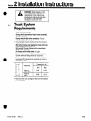
Truck System
Requirements
2.1
* Truck relief valve setting:
Clamps with conventional check valve assembly:
2000 psi maximum
Clamps with Hi-Ball valve assembly: 1700 psi
minimum, 2000 psi maximum
l
Truck hydraulic system should provide the following
rates of flow:
20C Carton Clamp and Appliance Clamp with conventional check valve: 2-6 gpm
35C and 60C Carton Clamps with conventional
check valve: 8-18 gpm.
All Clamps with Hi-Ball valve: 3-7 gpm
* Recommended hose and fitting size: No. 8 (1/2 inch
ID) with minimum fitting orifices of 13/32 inch.
l
Truck carriage must conform to the Industrial Truck
Association (ITA) dimensional standards as shown in
the following chart.
Dimension A (in.)
Mounting
Min.
I
Max.
Class II
(2OC, 35C)
Class III
KW
* Make sure the truck carriage is clean and the notches
are undamaged.
Form 5191
Rev. 0
6-2
Section
2.2
2 InstallationInstructions
Prior to Installation
NOTE: The Junction Blocks on
your Truck may be Reversed
from those Shown.
1. Install the hydraulic hoses to the truck junction
blocks using the correct Cascade Attachment Installation Kit. The part numbers are as follows:
Conventional
Check Valve
Port B
(Close)
Carton Clamps with a conventional valve: C-663587
\
I
Port SL
Carton Clamps with a Hi-Ball valve: C-663586
Appliance Clamp wlth a conventional valve:
C-663639
Appliance Clamp with a HI-Ball valve: C-663640
OR,
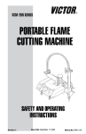
use hoses and fittings as shown in Figure 1, 2, 3, or 4.
Be careful not to pinch, twist, or otherwise damage the
hoses.
IMPORTANT
In order to conform to industry standard practice, the
hoses should be connected to the truck auxiliary valves
as indicated by the following chart.
Function,
in order of
location
from
Attachment
operator
Movement
1 Junction 4
/ / {Block
Lb- ..-e.i--d
ViEWED
Motion of the operator’s hand
-
!----
iI
Ij
FROM THE DRIVER’S
Block
i I
SEAT
w
Figure 1. Plumbing Diagram, Carton
Clamps with a Conventional Valve
Sideshift Right Rearward or Up
Sideshift
Sideshift Left
Forward or Down
Clamp (close)
Rearward or Up
Clamp
Release (open) Forward or Down
CAUTION:
2. Flush the hoses as follows to prevent damage to the
attachment check valve assembly and the cylinders.
Refer to the appropriate plumbing diagram.
a. Connect the hoses from each junction block
together.
b. Start the truck and actuate the truck control valves
in both directions for about 30 seconds to carry any
debris left in the hoses to the truck hydraulic tank and
filter.
6=3
Form5191
Rev.0
Section
2 InstallationInstructions
Hose
n
Hi-Ball Valve
\
Port B
(Close)
Straight
Thread
Connector
90” Swivel Elbow
Conventional
Check
Valve
.
Thread Elbow
II
into Port
--i--”
W_Block
w
VIEWED
u
Shit-off
Valves
FROM THE DRIVER’SSEAT
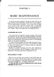
Figure 3. Plumbing Diagram, Appliance Clamp
with a Conventional Valve
Figure 2. Plumbing Diagram, Carton
Clamps with a Hi-Ball Valve
VIEWED
FROM THE DRIVER’S
SEAT
Hi-Ball
Valve
Into
Port\
OP
Port CL
90” Straight
Thl ,ead
Elb tow
I
/
I0
0
90” Swivel
Elbow
I
Straight
Thread
Connect01
/
,
“I
y
Straiaht
_ Thread
Connector’
Shut-off
Valves
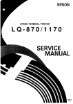
Figure 4. Plumbing Diagram, Appliance
Clamp with a Hi-Ball Valve
Form 5191
Rev. 0
6-4
2 InstallationInstructions
Section
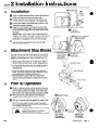
Installation
2.3
1
Using a suitable hoist and chain, position the clamp as
shown and remove the lower mounting hooks.
2
Position the truck close enough so the hoses on the
junction blocks can be connected to the attachment.
3
Connect the hoses to the attachment as shown in the
appropriate plumbing diagram.
4
Raise the truck carriage and engage the attachment
upper mounting hooks. Make sure the centering block
on the attachment aligns with the center notch on the
carriage.
Lower Mounting
Hooks
IMPORTANT: Some models have a positioning block
welded to the inside of the upper mounting hook. Center
the attachment on the carriage, making sure the positioning block is engaged in a notch on the carriage.
5
Tilt the mast back and install the lower mounting hook.
Lube-torque the capscrews to 103-113 ft.-lb. (35C,
Class II—64-69 ft.-lb.).
Attachment Stop Blocks
2.4
Cascade recommends that a steel block be permanently
welded on each side of the truck carriage upper crossbar
adjacent to each attachment upper mounting hook. To
perform the installation:
Lube Torque to:
b
103-l
13 ft.-lb.
(352. Class I I 1 64-69
ft.-lb.)
j
1. Select square steel stock with a width about equal to
the flat of the carriage upper crossbar (dimension A).
Tilt Back and
Install Lower
Mounting Hooks
Attachment
Upper
/Mounting
Hook
2. Cut two blocks from the stock, each about as long as
the width of the attachment upper mounting hook
(dimension B).
Steel Stop Block
3. Position the blocks adjacent to the upper mounting
hooks. The blocks should not extend behind the flat of
the carriage upper crossbar (dimension A).
4. Weld the blocks in place. Make sure you protect
adjacent hoses and hydraulic components from weld
splatter.
Prior to Operation
2.5
1
Check the cylinder anchor nuts to make sure they are
secure. If your clamp has old-style anchor nuts, make
sure the spring retainer is in place. If you have newstyle anchor nuts, make sure they are properly staked.
2
Before picking up a load, operate the attachment
through several cycles to force any air from the
system to the truck hydraulic tank. Check for leaks.
3
Pick up a maximum load and operate the clamp. If the
clamp does not function correctly, recheck the plumbing. If the clamp drops the load, contact Cascade’s
Service Department, telephone 800-547-5266 (toll-free),
or, in Oregon, call 666-1511.
A
6-5
WARNING: Make sure there are no
people in the vicinity of the attachment when picking up a load.
Stake Here
OLD-STYLE
CYLINDER
ANCHOR NUT
NEW-STYLE
CYLINDER
ANCHOR NUT
Form 5191
Rev. 1
Section
a
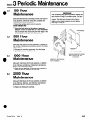
3.1
3 Periodic Maintenance
100 Hour
Maintenance
Every time the lift truck is serviced or every 100 hours of
truck operation, whichever comes first, complete the
following maintenance procedures.
IMPORTANT:
After completing any service procedure, always test
each function through 5 complete cycles. First test
the clamp empty to bleed excess air trapped in the
system. Then test each function with a load to
make sure the clamp operates correctly before
returning it to the job.
Ž Check the cylinder anchor nuts for security.
Carton Clamps Only
Ž Check the hard facing on the bottom of each arm
stabilizer. If there is visible wear, or if your attachment
has an old-style wear shoe along the lower edge of the
arm, build up the surface with weld as shown.
3.2
tabilizer
500 Hour
Maintenance
After each 500 hours of lift truck operation, in addition to
the 100--hour maintenance procedures, perform the following procedure.
3.3
a
1000 Hour
Maintenance
/
W
Ž Retorque the mounting capscrews. Use the torque
specifications shown in Section 2.
.12”
(minimum
WELDING
ROD:
I
height)
SPECIFICATIONS
Stoody 2134,134
or equivalent
This Wear Shoe has been replaced by a Hard Facing on
the Arm Stabilizer
After each 1000 hours of lift truck operation, in addition
to the 100-hour and 500-hour maintenance procedures,
perform the following procedure.
Ž Check the arm bushings. If they are worn, marred, or
deeply scratched, replaced the bushings.
3.4
2000 Hour
Maintenance
After each 2000 hours of lift truck operation, in addition
to the 100-hour, 500-hour, and 1000-hour maintenance
procedures, perform the following procedure.
Ž Replaceall sliding arm bushings.
Form 5191
Rev. 0
6-6
Section
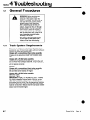
4.1
4 Troubleshooting
General Procedures
A
WARNING: Before servicing any
hydraulic component, relieve
pressure in the system. Open the
arms 1 or 2 inches, turn the truck off,
and open the truck auxiliary valves
several times in both directions.
After completing any service procedure, always test the unit through
several cycles. First test the attachment empty to bleed air trapped in
the system to the truck system. Then
test the attachment with a load to be
sure it operates correctly before
returning it to the job.
Stay clear of the load while testing.
Do not raise the load more than 3
inches off the floor while testing.
4.1-1
Truck System Requirements
Pressure: In addition to conforming to the following requirements, your lift truck must supply sufficient hydraulic
pressure to handle the heaviest load.
Clamps with a conventional check valve assembly
Pressure to the attachment MUST NOT EXCEED 2000
PSI.
Clamps with a Hi-Ball valve assembly
Pressure to the attachment should be no less than 1700
psi and MUST NOT EXCEED 2000 PSI. If your truck output does not conform to these tolerances, the attachment
will not operate correctly.
Volume:
Clamps with a conventional check valve assembly
20C Carton Clamp and Appliance Clamp: 2-6 gpm
35C and 60C Carton Clamps: 8-18 gpm
Clamps with a Hi-Ball valve assembly
Minimum: 3 gpm
Maximum: 7 gpm
IMPORTANT: HI-BALL ATTACHMENTS ONLY. If clamping pressure must be reduced below 1700 psi, an auxiliary relief valve (Cascade part number C-66041 2) must
be plumbed into the circuit. See the appropriate Hydraulic
Schematic (Paragraph 4.2-6 and 4.2-8). The relief setting
must be no less than 1000 psi and the truck pump volume
output must not exceed 6 gpm.
6-7
Form 5191
Rev. 0
Section
4.1-2
4 Troubleshooting
Tools Required
Pressure Gauge
In addition to a normal selection of hand tools, you will
need one each of the following for attachments with a
conventional valve and two each for attachments with a
Hi-Ball valve.
Pressure gauge capable of measuring pressures to
2500 psi.
No. 8 swivel nut run tee (37° JIC) suitable for mounting
gauges
24-inch
Needle shutoff valve, rated for 2500 psi service,
minimum. (Recommended supplier for needle shutoff
valve: Marsh Instrument Co., Skokie, Ill.)
Extension
Hose
/
Hose with female ends for use as a drain line.
No. 8 JIC cap for cylinder port.
Needle Shutoff
Valve
Swivel Nut
Run Tee
No. 8 JIC plug for hose end.
t
No. 8 O-ring-to-JIC straight adapter fitting.
/
Hose
Hose, 24 inches long.
APPLIANCE CLAMP WITH CONVENTIONAL CHECK
VALVE ONLY. Two steel sleeves as shown by the accompanying illustration.
iMPORTANT:
Make Sure The
Arrow Points in
This Direction.
1 inch
Get All The Facts Before You
Begin Working On The
Clamp
4.1-3
It is important that you gather all the facts regarding the
problem before you begin service procedures. The best
way is to talk with the operator. Ask for a complete
description of the malfunction. The following guidelines
will help you decide where to begin your troubleshooting
procedures.
l
l
l
-----
--
-----
--
1 314 inch
b-
24 inches-4
STEEL
v
SLEEVE
(For Appliance Clamps With
Conventional Valve Only)
Clamp arm(s) won’t operate properly. If you encounter
this problem, refer to Paragraph 4.3.
Clamp drops the load only when sideshifting. If you encounter this problem, refer to Paragraph 4.4.
Clamp drops the load after it has been gripped.
0 Clamp will not carry loads up to the rated capacity of
the clamp.
If you encounter one of these problems, refer to the
following appropriate Paragraph.
Carton Clamps with a conventional check valve:
Paragraph 4.5
Appliance Clamps with a conventional check valve:
Paragraph 4.6
Any attachment with a Hi-Ball valve: Paragraph 4.7
Form 5191
Rev. 0
6=6
Section
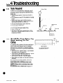
4.2
4.2-1
4 Troubleshooting
Plumbing
Hosing Diagram, Carton Clamps
with ConventionalValve
Junctio
Block
Hose
Reel
ARMS CLOSING
PRESSURE
-
RETURN
~ZI==ZX
Junction
Block
ARMS OPENING
PRESSURE
RETURN
6=9
..~.
Form 5191
Rev. 0
Section
6
4.2-l
4 Troubleshooting
Hosing Diagram, Carton Clamps
with ConventionalValve (Cont.)
Junctio
Block
Hose
Reel
SIDESHIFT
Junction
LEFT
PRESSURE
RETURN
4.2-2
..‘..... ” .‘..
Circuit Schematic, Carton Clamps
with Conventional Valve
111 “,I-
! Check
NOTE: Junction
Valve
I-II
‘*ar
Truck Relief Valve
Form 5191
Rev. 0
eulic
Pump
6-10
Section
4.2-3
4 Troubleshooting
Hosing Diagram, Appliance Clamp
with ConventionalValve
Junction
Block
Check
Valve
Junction
Block
ARMS CLOSING
PRESSURE
_....... ...‘.
..%.
R ETU RN
Check
Valve
Junction
Block
ARMS OPENING
PRESSURE
RETURN
6-11
-
‘....=-<
Form 5191
Rev. 0
Section
4.2-3
4 Troubleshooting
Hosing Diagram, Appliance Clamp
with ConventionalValve (Cont.)
Check
Valve
SIDESHIFT
Junction
Block
LEFT
PRESSURE
RETURN
0
4.2-4
A .:. .. / .... :::.
Circuit Schematic, Appliance Clamps
with Conventional Valve
ders
Check
Valve
.Si~;;~l$i ng
C
Valves
Junction
Block --j
--i
,
-.
__-
‘2
Truck Relief Valve
Form 5191
Rev. 0
Pump
Section
4.2-6
4 Troubleshooting
Hosing Diagram, Carton Clamps
with Hi-Ball Valve
ARMS CLOSING
PRESSURE
-
RETURN
*’
.. ..,.:::.
ARMS OPENING
PRESSURE
,RETURN
6-13
Junction
Block
-..
::...
Form5191
Rev.0
Section
4 Troubleshooting
4.2-5 Hosing Diagram, Carton Clamps
with Hi-Ball Valve (Cont.)
SIDESHIFT
LEFT
PRESSURE
RETURN
4.2-6
.... ....... .. ~....
Circuit Schematic, Carton Clamps
with Hi-Ball Valve.
I
2
,
I
I
Clamp
Truck
Form 5191
Rev. 0
Are not Serviceable
Check Valves
6-14
Section
4.2-7
4 Troubleshooting
Hosing Diagram, Appliance Clamp
with Hi-Ball Valve
Sideshifting
Shutoff
Valve
Junctio
Block
Hos
Ree
ARMS CLOSING
PRESSURE
RETURN
z==zzz
Sideshifting
Shutoff Valve
ARMS OPENING
PRESSURE
RETURN
6-15
--. . .. ...-. i ..i...
Form5191
Rev.0
Section
0
4.2-7
4 Troubleshooting
Hosing Diagram, Appliance Clamp
with Hi-Ball Valve (Cont.)
Junctio
Block
Hos
Flee
SIDESHIFT
PRESSURE
RETURN
4.2-8
LEFT
I../. ... .. ...... ..
Circuit Schematic, Appliance Clamp
with Hi-Ball Valve
I
Cylinders
I
hll
I
1
1
r
Hi-Ball
Valve
l =Cartridge
Valves
Are not Serviceable
Sideshift
Truck
Valve
-W
Truck
Form 5191
Rev. 0
Relief
Valve’
Truck
Pump
Hydraulic
Pressure Relief
OPTIONAL
Valve
(C-6604121
8-16
Section
4.3
4 Troubleshooting
Checking Truck
output
If the clamp arm(s) won’t operate properly, make sure the
truck system output conforms to the Truck System Requirements (Paragraph 4.1-1) before performing pressure
tests on the attachment.
Correct volume output (gpm) is especially important on
clamps with a Hi-Ball valve. You should check for the
specified output with an accurate flow meter at the truck
carriage (junction block). If output is not as specified,
your truck system may have to be adjusted or modified
accordingly. If your truck will not achieve the specified
output and you have a clamp with a Hi-Ball valve, your attachment may have to be modified to use a conventional
valve.
Contact Cascade’s Service Department if you have any
questions.
4.4
Clamp Drops the
Load Only When
Sideshifting
If you encounter this problem with your clamp, check the
following before performing pressure tests on the
attachment.
4.4-1
Appliance Clamp
Make sure the sideshifting shutoff valves are secure and
adjusted properly. The valve mounting should be adjusted
so the plunger is fully depressed by the trailing arm (right
arm when sideshifting left and vice versa) just before
that arm reaches the end of its stroke.
4.4-2
Carton Clamps
If you are handling relatively narrow loads, the trailing
arm (right arm when sideshifting left and vice versa) may
be reaching the end of its stroke before the leading arm.
If possible, arrange your handling process to allow
sideshifting the other direction. If this is not practical,
contact Cascade’s Service Department.
4.4-3
Clamps Controlled with One
Auxiliary Valve and a
Solenoid Valve
If your unit is plumbed to “sideshift” when the solenoid
valve is energized, replumb the circuit so the “clamp”
function operates when the solenoid valve is energized.
6-17
Form 5191
Rev. 0
4 Troubleshooting
Section
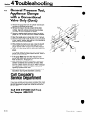
General PressureTest,
Carton Clamps with a
ConventionalValve
Only
4.5
0
Ž Open the arms completely to gain access to the check
valve ports.
Fitting
/aA
d7l\
To
Pressure
Gauge\I\ AL
.
’
\
//w
1
Port C
I
i
/
To Cylinder
Rod Ends
Ž Locateand identify Port C on the check valve and
disconnect the cylinder hose from the elbow. Install
the gauge and tee into the elbow as shown, then
reconnect the cylinder hose to the open end of the tee.
• Close the arms completely. Make sure the gauge
assembly does not interfere with the closing arms.
Ž Pull the control handle to the “clamp”
hold for a few seconds.
Ž Return the handle to neutral. The gauge should
register within 100 psi of specified truck pressure. If it
does not, check the pressure delivered by the truck.
Refer to the truck service manual. Adjust and repair as
necessary. TRUCK PRESSURE MUST NOT EXCEED
2000 PSI. Recheck cylinder pressure.
l
l
Pressbre &2+--------j
/-
position and
If the truck system is OK, watch the gauge. If it
registers a drop of more than 100 psi in one minute,
check for hydraulic leaks in the system. Refer to the
accompanying diagram. Repair the leaks and recheck
the pressure.
If the truck system is OK and the gauge does not drop
more than 100 psi in one minute and you are having
trouble picking up or carrying a load, the problem is
not hydraulic. Refer to the Arm Service section,
Paragraph 5.2-2 or 5.2-3, or call Cascade’s Service
Department.
Extension
Junction
Block
1 !bf------A---
__~__
tl-__
--I- -9
u
Cylinder
I
/
..
4 Check
* Valve
* If there are no leaks and the gauge does drop more
than 100 psi in one minute, complete the following additional test to locate the source of the problem (page
6-19).
Truck
Auxiliary
Valve
POTENTIAL
LEAK POINTS
Form5191
Rev.0
6-18
Section
4.5
4 Troubleshooting
General PressurePest,
Carton Clamps with a
ConventionalValve
Only (Cont.)
Ž Open the arms fully.
To
Pressure
Ž Disconnect the hose to the gauge tee and plug the
hose.
Ž Install the needle valve and drain line to the open end
of the tee. Put the drain line in a suitable container.
Plug the
F
Ž Open the needle valve no more than 1/2 to 1 turn.
Ž Startthe truck and let it idle. Put the truck clamp lever
to the “clamp” position and hold for 4 or 5 seconds to
allow oil to flow to the container.
Ž While holding the clamp valve open, close the needle
shutoff valve. Keep holding the truck valve open until
the gauge reaches within 100 psi of truck relief
pressure.
le
Install
’ Needle Shutoff
Valve
VIEWED FROM
THE REAR
n
1
Ž Return the truck clamp valve to neutral and watch the
gauge.
* If the gauge does not drop more than 100 psi in one
minute, one or both cylinders require service. Refer to
Section 5, Paragraph 5.3.
l
If the gauge does drop more than 100 psi in one
minute, the check valve is faulty and requires service.
Refer to Section 5, Paragraph 5.6.
q After making the necessary corrections, reconnect the
hoses. Cycle the clamp 4 or 5 times without and with a
load before returning it to service.
Call Cascade’s
Service Department
If you have carefully and accurately completed this check
list and you still have not solved the problem, call us. Our
Service Department is open from 10:00 AM to 8:00 PM
Eastern time.
Call 800-547-5266(toll free)
In Oregon, 666-4511
6=19
Form 5191
Rev. 0
4 Troubleshooting
Section
General PressureTest,
Appliance Clamps
with a Conventional
Valve Only
4.6
Slip on
the Sleeves
Ž Open the arms completely.
Ž Disconnect the cylinder rod ends from the arms.
IMPORTANT: Refer to the procedures described in
Section 5, Paragraph 5.2-1, Step 2.
Ž Retract the cylinders far enough to slip the steel
sleeves over the cylinder rods.
• Extend the cylinders and reconnect the rods to the
arms with the sleeves in place. It is not necessary to
“lock” the nuts or install the keepers.
Ž Remove the supply hose to the rod end port of one
cylinder. Install a gauge into the open port, then reconnect the cylinder supply hose to the gauge tee.
Ž Slowly retract the cylinders (arms moving together)
until the sleeves contact the’cylinder end. Make sure
the gauge assembly does not interfere with the closing
arms. The cylinders are now blocked partially open.
Ž Puil the clamp control handle to the “clamp”
and hold for a few seconds.
0
position
Ž Return the handle to neutral. The gauge should
register within 100 psi of specified truck pressure.
.
.
.
If it does not, check the pressure delivered by the
truck. Refer to the truck service manual. Adjust and
repair as necessary. TRUCK PRESSURE MUSTNOT
EXCEED 2000 PSI. Recheck cylinder pressure.
If the truck system is OK, watch the gauge. If it
registers a drop of more than 100 psi in one minute,
check for hydraulic leaks in the system. Refer to the
accompanying diagram. Repair the leaks and recheck
cylinder pressure.
If there are not external leaks, test the check valve as
follows (page 6-21).
/
Cylinder
1,
\
p
q
c
/r Valve
P
I
..
3
F
u
POTENTIAL
LEAK POINTS
Form 5191
Rev. 0
6-20
4Troubleshooting
Section
4.6
General Pressure Test.
Appliance Clamps
with a Conventional
Valve Only (Cont.)
Ž Remove the gauge tee from the cylinder rod end port
but keep it connected to the hose.
Ž Remove the hose to the rod end port of the other
cylinder. Cap both cylinder ports and plug the hose
that does not have the gauge connected.
Ž Connect a needle shutoff valve and drain line to the
gauge tee. Put the drain line into a suitable container.
Ž Open the needle valve no more than 1/2 to 1 full turn.
• Start the truck and let it idle. Put the truck clamp lever
to the “clamp” position and hold for 4 or 5 seconds to
allow oil to flow to the container.
Ž While holding the clamp lever open, close the shutoff
valve. Keep holding the truck valve open until the
gauge reaches within 100 psi of truck relief pressure.
q Return the truck clamp valve to neutral and watch the
gauge.
Valve
* If the gauge does not drop more than 100 psi in one
minute, one or both cylinders require service. Refer to
Section 5, Paragraph 5.3.
l
If the gauge does drop more than 100 psi in one
minute, the check valve is faulty and requires service.
Refer to Section 5, Paragraph 5.6.
q After making the necessary corrections, remove the
cylinder rod sleeves and reconnect all hoses. Make
sure the cylinder anchors are secure. Refer to Section
5, Paragraph 5.2-1, Step 6 for special instructions
regarding cylinder anchor nuts.
Ž Cycle the attachment 4 or 5 times without and with a
load before returning the attachment to service.
Call Cascade’s
Service Department
If you have carefully and accurately completed this check
list and you still have not solved the problem, call us. Our
Service Department is open from 10:00 AM to 8:00 PM
Eastern time.
Call 800-447-5266(toll free)
In Oregon, 666-4511
Form 5191
Rev. 0
Section
4 Troubleshooting
TroubleshootingTests,
Clamps with a Hi-Ball
Valve Only
4.7
OperationalTests
4.7-1
If you are having trouble with a clamp equipped with a HiBall valve, check the following before performing the
General Pressure Test (Paragraph 4.7-2).
Make sure the truck hoses are the same size as those
used on the attachment. They must be No. 8 with
minimum fitting orifices of 13/32 inch. A flow divider
can be used to reduce the volume delivered to the
attachment.
l
Make sure the attachment is plumbed to the truck correctly. Refer to the Hosing Diagram or Circuit
Schematic (Paragraph 4.2) for your system.
l
* Make sure the truck pump supplies the specified
volume to the attachment at the carriage (junction
block). 3 gpm minimum; 7 gpm maximum. If a pressure
regulator is used, volume to the attachment must not
exceed 6 gpm.
NOTE: If your truck output exceeds the specified maximum, a flow divider may be installed to provide the
correct output.
Make sure there are no hydraulic leaks in the system.
l
If these conditions are met, check for proper operation of
the Hi-Ball valve according to the following procedures.
1. Open the attachment arms and install a pressure
gauge and, tee into valve Port CL as shown.
2. Making sure the gauge assembly does not interfere,
operate the attachment several times and watch the
arms to be sure the valve is operating properly.
IMPORTANT: “Feather” the control valve instead of
operating at full speed so you can more easily observe
the movement of the arms.
Tee Fitting
\
To Pressure _
VIEWED FROM
THE REAR
To Truck ’
Junction
Block
24-Inch
Extension
Hose
The following should happen when the arms are closing
from the fully-open position.
Both arms should begin closing simultaneously. The
right arm should complete its travel first.
The left arm should hesitate before completing its final
4-6 inches of travel.
As soon as the right arm reaches the end of its travel
and immediately before the left arm continues to
move, the system pressure should increase to approximately 1650 psi (warm oil). If it does not, lift truck
pressure must be adjusted to 1700 psi minimum. DO
NOT EXCEED 2000 PSI.
The pressure should then drop as the left arm
completes its final 4-6 inches of travel.
If the system does not pass these tests, the Hi-Ball valve
is faulty and should be replaced.
If the system does pass these tests and the clamp will
not handle the load, remove the gauge from Port CL and
perform the following General Pressure Test.
Form 5191
Rev. 0
6-22
Section
4 Troubleshooting
General PressureTest
4.7-2
q Open the arms completely to gain access to the check
valve ports.
Ž Install pressure gauges with tees in Ports R1 and R2 of
the Hi-Ball valve as shown.
Ž Close the arms completely. Make sure the gauge
assemblies do not interfere with the closing arms.
Ž Pull the control handle to the “clamp” position and
hold for a few seconds after the left arm has completed its travel to pressurize the clamp circuit.
X-Inch
Extension
Ž Return the valve handle to neutral and watch the
gauges.
0 If the gauges drop no more than 100 psi in one minute
and the attachment still fails to operate correctly, the
problem may be due to incorrect application of the attachment or an auxiliary relief valve may be set too
low to handle your loads.
0 If either or both gauges do drop more than 100 psi in
one minute, continue testing as follows to isolate the
problem.
VIEWED FROM
THE REAR
To Pressurg
Gauges
I
-port
Rl
Port R2
24-inch
Extension
Hoses
• Open the arms and disconnect the hoses from the
gauge tees that lead to the cylinder rod end ports.
Ž Attach needle valves and drain lines to the gauge tees.
Open both needle valves no more than 1/2 to 1 full
turn and put the drain lines in a suitable container.
Ž Move the control handle to the “clamp”
cause a flow of oil at the drain hoses.
position to
Ž Continue holding the control handle and close both
needle valves tightly. Hold the control handle to
“clamp” until the circuit is fully pressurized.
Ž Return the handle to neutral and watch the gauges.
l
If either or both gauges drop more than 100 psi in one
minute, the Hi-Ball valve is faulty and must be
replaced.
* If neither gauge drops more than 100 psi in one
minute, one or both cylinders require service. See
Section 5, Paragraph 5.3.
Ž After making the necessary corrections, remove the
gauges and reconnect the hoses. Cycle the attachment 4 or 5 times without and with a load before
returning it to service.
Call Cascade’s
Service Department
To Press
Gauges
I
If you have carefully and accurately completed this check
list and you still have not solved the problem, call us. Our
Service Department is open from 10:00 AM to 8:00 PM
Eastern time.
Call 800-227-5266(toll free)
In Oregon, 666-4511
6-23
Needle Shutoff
Valves
To Suitable
Container
Form 5191
Rev. 0
Section
5 Service
Clamp Removal and
Installation
5.1
0
1
Open the clamp arms completely.
2
Remove the lower mounting hooks. For reassembly,
lube-torque the lower mounting hook capscrews to
103-113 ft.-lb. (35C, Class I—64-69 ft.-lb.).
3
Position wooden blocks or a shipping pallet under the
attachment. Lower the mast carriage until the attachment is resting on the blocks.
4
Continue lowering the mast carriage enough to clear
the upper mounting hooks. Back the truck away a
few inches to gain access to the hoses to the
attachment.
Lower Carriaae and
Back Truck Away Slightly.
WARNING
Lower CaTage until
Attachment Rests
on Pallet.
5
Disconnect and cap the hoses to the attachment. Tag
the hoses for ease in reconnecting.
6
For reinstallation, reverse the above procedures, or
consult the Installation Instructions, Section 2.
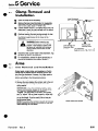
5.2
Arms
5.2-1
Arm Removaland Installation
Remove Lower
Mounting Hooks
Contact pads, contact plates, and equalizers on Carton
Clamps can be removed without removing the arm carriers from the attachment. However, the rubber pads on
Appliance Clamp arms are not replaceable. Remove arm
carriers according to the following procedures.
1. Open the arms past the clamp frame.
2. Remove the nuts retaining the cylinder rods to the arm
lugs. On old-style retaining nuts, first remove the
spring washer.
IMPORTANT: A new style retaining nut has a coneshaped locking washer swaged to the threads of the
nut. Locking is achieved when the washer is
“dimpled” into the groove in the end of the cylinder
rod. To “unlock” the nut, insert a punch or chisel into
the hole in the center of the cone-shaped washer and
pry up the dimple. If you’re careful, the nut may be
reused several times.
NOTE Pressurizing the cylinders outward will increase
friction between the cylinder rod and the lug and may
make loosening the nuts easier.
Form 5191
Rev. 0
Carton Clamp Arm Shown
6=24
Section
5.2-1
5 Service
Arm Removal and Installation (Cont.)
3 Secure the arms with a suitable overhead hoist and
chain.
A
WARNING: Make sure your
overhead hoist has a rated lifting
capacity of at least 1000 pounds.
4 Retract the cylinder rods until they come out of
engagement with the arm lugs.
5 Pull the arms out of the clamp frame.
IMPORTANT: Each time the arms are removed, inspect the arm guide tubes for scoring. Minor scoring
can be removed with a hone. If the guide tubes are
badly damaged, the frame must be replaced. Before installing arm carriers, make sure the guide tubes are
clean and free of metal projections.
Washer
Lug
Make Sure
Spring
\
6 For reassembly, reverse the above procedures, except
for the following special instructions for cylinder
anchor nuts.
NOTE: When tightening cylinder anchor nuts,
pressurizing the cylinders outward will increase friction
between the cylinder rod and the lug and may make
tightening easier.
a. OLD-STYLE ANCHOR NUTS. Install the washer
onto the cylinder rod, then fit the cylinder rod into the
arm carrier. Install the sleeve, then thread on the nut.
Tighten the nut until the sleeve bottoms against the
washer. Back the nut off until it aligns with the slot in
the cylinder rod. Install the spring retainer. The
clearance between the lug and the washer should be
about 5/32 inch.
N:t
OLD-STYLE CYLINDER ANCHOR NUT
CAUTION: Do not attempt to remove the looseness or
damage to the assembly could result.
b. NEW-STYLE ANCHOR NUTS.
NOTE: Service replacements for old-style anchor nuts
are of the new-style configuration.
Install the washer onto the cylinder rod with the
counterbore-side facing outward (toward the nut), then
fit the cylinder rod into the arm carrier. Restrain the
washer with a wrench and torque the nut to: 20C and
35C—55-65 ft.-lb.; 60C—130-150 ft.-lb. Lock the nut
by staking the cone-shaped washer with a casehardened chisel. Be sure the washer is driven into the
slot in the end of the cylinder rod.
Counterbored
Washer
Lug
NEW-STYLE CYLINDER ANCHOR NUT
CAUTION: Always use the hex-style washer with the
new-style anchor nut. DO NOT use the old-style
castellated nut with the hex-style washer.
6-25
Form 5191
Rev. 0
5 Service
Section
0
Arm Disassembly,Service,
and Reassembly,
Carton Clamps
5.2-2
The following procedures can be performed with the arms
on the attachment and with the attachment on the truck.
For Reassembly
Lube Toraue to:
1 %$%6~~;;.;“,.ft.-lb.
Arm Carrier(T-bar shown)
Arm Base
/
Remove the
Stabilizer
NOTE: The contact plate does not have replaceable
pads. If a pad is completely worn, the contact plate must
be replaced.
1
Remove the contact plate from the stabilizer.
2
Remove the stabilizer by removing the two pivot pins
that secure it to the arm base.
Inspect the stabilizer pivot bushings. If the nonmetallic coating is worn through or if the bushing ID
is worn, replace the bushing.
3
CAUTION: Use a bushing driver to replace the
bushings. Do not damage the bushing ID.
4
Remove the arm carrier (either T-bar or integral).
5
Reassembly is a reverse of disassembly.
NOTE: The camber of the contact plates can be adjusted by removing the top spacer between the contact plate and the stabilizer. If even more camber is
required, combine the top spacer with the bottom
spacer.
5.2-3
Arm Disassemblyand
Reassembly,Appliance
Clamp
Spacer
NOTE: Clamps manufactured
prior to June 1975 had replaceable Wear Shoes on
bottom of the Contact
Plates. These Shoes have
been replaced by a Hard
Facing which is Welded to
all Replacement Stabilizers.
Refer to the Periodic
Maintenance Section,
Paragraph 3.1 for procedures
for Field installation of
, the Facing.
Arm
The rubber pads on Appliance Clamps are not
replaceable. If the pad is worn or if the arm is damaged,
the complete arm assembly must be replaced. The left
hand and right hand arms are not interchangeable.
The arm carrier can be removed and reinstalled in the
same manner as Carton Clamps.
Form 5191
Rev. 0
6-26
5 Service
Section
SlidingArm Bushing
Replacement,Two-pieceStyle
5.2-4
NOTE: An attachment with two-piece bushings may be
converted to the new style, one-piece configuration by the
installation of the appropriate One-Piece Bushing
Conversion Kit. Contact Cascade Customer Service for
information.
1
Remove and discard the old long and short bushings.
To ease removal, spread the short bushing by inserting a screwdriver blade into the bushing slot. Similarly, insert two screwdrivers into two opposing slots in
the long bushing to disengage the bushing retaining
lip. It may be necessary to drive off the long bushing
with a block and a hammer.
2
Install the long bushing. Spread the slots of the
bushing with screwdrivers as during removal. If the
bushing will not go over the arm carrier bar, heat it in
boiling water for 3 or 4 minutes to soften it. Make
sure the bushing retaining lip engages the groove in
the arm carrier bar.
3
Install the short bushing. Spread the bushing to ease
installation. Make sure the bushing fits into the outermost groove in the arm carrier bar.
4
Lubricate the bushings before assembling arm
carriers onto the attachment.
Short Bushing
SlidingArm Bushing
Replacement,One-pieceStyle
6.2-5
1
Remove the bushing retainer snap ring and washer
from the end of the arm carrier bar.
2
Slide off the old bushing.
3
Slide the new bushing on and install the washer and
retaining snap ring.
4
Lubricate the bushings before assembling arm
carriers onto the attachment.
Remove the
Snap Ring and Washer
6-27
Form5191
Rev.0
5 Service
Section
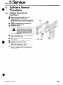
0
Cylinders,General
Procedures
5.3
Cylinder Removal and
Installation
5.3-4
1
Extend the arms past the width of the frame.
2
Remove the cylinder rod anchor nuts.
IMPORTANT: Refer to the procedures pertaining to
cylinder anchor nuts as described in Paragraph 5.2-1,
Step 2.
3
Retract the cylinder rods until they come out of
engagement with the arm lugs.
4
Remove the backrest.
hoses, relie\e pressure that might be
control valves several times in both
5
Remove and tag the hoses to the cylinders. Cap the
hoses and the cylinder ports.
6
Remove the cylinder shell anchor nuts (Paragraph
5.2-1, Step 2).
7
Lift the cylinders away from the clamp frame.
8
Installation is a reverse of removal.
Backrest
20C CARTON
CLAMP SHOWN
IMPORTANT: Refer to the procedures pertaining to
anchor nuts, Paragraph 5.2-1, Step 6.
9
Form 5191
Operate the attachment through several full cycles to
force air in the system to the truck hydraulic tank.
Check for leaks.
Rev. 0
6-26
5 Service
Section
Cylinder Disassembly
5.3-2
l
l
l
l
5.3-3
Use a pin-type spanner wrench to remove cylinder
retainers.
When servicing a cylinder, clamp it in a soft-jawed
vise. Clamp the cylinder and the rod on the major
diameter at the extreme end only. Never clamp the
cylinder rod sealing surface.
V-seals will slide off the piston easily. To gain access
to the rod seals, remove the self-adjusting brass
bushing from the retainer after the retainer has been
removed.
To remove a U-cup seal from a piston, put the piston
in a soft-jawed vise. Pry the seal up with a blunt tool
such as a screwdriver, then cut the seal to remove it.
Be careful not to scratch the seal groove.
Do Not Clamp R
On Threaded or
Sealing Surfaces.
Clamp Only at
Extreme End of
Major Diameter.
Cylinder Inspection
Inspect the rod, piston, and retainer for nicks or burrs.
If deeply gouged, replace the part. Minor nicks and
burrs can be removed with an emery cloth.
NOTE: A minor nick is one that will not cause a
bypass of oil when the cylinder is operating.
Inspect the inside of the cylinder shell and remove any
minor nicks and burrs (see Note, above) with a butterfly hone. Replace the cylinder shell if it is deeply
gouged.
On cylinders with V-seals, inspect the self-adjusting
brass bushing that fits inside the retainer. If the ID is
scored, the bushing should be replaced.
5.3-4
Cylinder Reassembly
Lubricate all new seals before installing. Use a mixture
of petroleum jelly and hydraulic oil on seals.
Clamp Shell Only
At Extreme
Base End.
Remove Seal from
Piston. Do Not
Scratch the Groove.
Carefully note the direction of seals. If they are installed backwards, the seals will not seal properly.
Refer to the illustration of the cylinder you are
servicing.
When installing U-cup seals onto a piston, hook one
side of the seal in the groove and push it over the
piston.
NOTE: Polishing the chamfer angle will allow the seal
to slide into the groove much easier.
Always reassemble the rod assembly by sliding the retainer on first, then the piston assembly. Install and
torque the piston retaining nut before sliding the rod
assembly back into the shell.
When reassembling a cylinder, always observe all
torque values as shown on the appropriate illustration.
Form 5191
Rev. 0
Section
5 Service
CylinderService
5.4
Read the General Procedures, Paragraph 5.3, before
proceeding.
5.4-1 Cylinders with V-seals
1
Remove the setscrew from the threaded washer.
2
Remove the threaded washer.
3
4
Pull the rod assembly out of the shell.
Remove the nut securing the piston to the rod.
5
Remove the self-adjusting brass bushing from the retainer to gain access to the rod seal.
6
Remove the pistons and retainer and replace all
seals.
BeSureto
ReplaceThisSeal.
\
Removethe Bushing
fromthe Retainer
RemovePistonsand
Retainerand Replace
All Seals
Remove the
Rod Assembly
Cylinders with U-cup Seals
5.4-2
1
Remove the retainer.
2
Pull the rod assembly out of the shell.
3
Remove the nut securing the piston to the rod.
4
Remove the piston and retainer and replace all seals.
Remove the Retainer
Remove the
Rod Assembly
Be Sure to
Replace This Seal
Remove the Nut
Lube Torque to:
20C - 50-60 ft.-lb.
Form5191
Rev.0
Remove Pistons and
Retainer and Replace
All Seals.
Remove the Threaded Washer
b
5 Service
Section
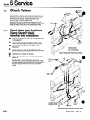
Check Valves
5.5
Standard Carton Clamps and Appliance Clamps have a
sliding-spool fluid control valve that serves as a check
valve and a flow divider. Hi-Ball attachments are
equipped with a special Hi-Ball valve.
Appliance Clamps are additionally equipped with two
sideshifting shutoff valves to control the flow of oil to the
clamp cylinders at the end of the sideshifting stroke.
Check Valve (and Appliance
Clamp Shutoff Valve)
Removal and Installation
5.5-1
1
Remove the attachment from the truck as described
in Paragraph 5.1.
2
Remove, cap, and tag the hoses or tubes to the
check valve (and Appliance Clamp shutoff valves).
3
Remove, cap, and tag the truck hoses to the
attachment.
4
Remove the check valve (and Appliance Clamp
shutoff valves) by removing the capscrew
securing
the valve to the attachment frame.
5
6
Installation is a reversal of removal.
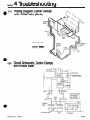
THE FRONT OF
THE ATTACHMENT
Carton Clamp with Fluid Control Valve
Install the attachment onto the truck as described in
Section 2.
IMPORTANT: APPLIANCE CLAMP SHUTOFF
VALVES ONLY. When installing shutoff valves, make
sure the adjustable stop leaves 0.20 inch of travel on
the valve plunger when the arms are completely
closed.
VIEWED FROM THE
FRONT OF THE
ATTACHMENT
Appliance Clamp with Fluid Control Valve
Form 5191
Rev. 0
Section
5 Service
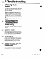
THE ATTACHMENT
Carton Clamp with Hi-Ball Valve
9
Remove
)thdt-Ball
m
Remove
Hose
++%
wShut-off
Valve
Remove
Remove the
Shut-off Valves
VIEWED FROM
THE FRONT OF
THE ATTACHMENT
Appliance Clamp with Hi-Ball Valve
Form5191
Rev.0
6=32
Section
5.5-2
5 Service
Check Valve Service
IMPORTANT: Service the fluid control valve in a clean
work area.
1
Using the special wrench (Cascade part number
C-2645) provided with the valve seat repair kit, remove
the allen-head plugs from both ends of the valve. If the
special wrench is not available, use a No. 5 JIC fitting
cap.
2
Carefully remove the internal parts and lay them out
in the correct order on the work bench.
CAUTION: The balls can become lodged in the internal ports during disassembly. Make sure the balls
are removed before proceeding.
3
Remove the hex-head plugs from both ends of the
valve.
4
Carefully remove the internal parts and lay them out
in the correct order on the work bench.
5
Clean all internal parts with kerosene or cleaning
solvent.
6
Replace the springs, O-rings, and ball seats using
Cascade’s valve seat repair kit.
7
Insert the piston, pin,
and spacer (the end
with the small hole goes
in first into the valve
body).
8
Coat both seat O-rings
with Vaseline or
equivalent. Insert each
O-ring into its check
cavity area, then insert
the seat and press it in
place.
9
Insert the remaining
components in the order
shown.
OLD STYLE CONFIGURATION
If the internals of your valve look like
these parts, a seal kit, part number
C-652895, is available to update vour valve
-r”‘a
Remove the Componentsv
Before
inserting the spring,
make sure the ball is
properly seated.
CAUTION:
10
Valve
Body
Remove
the
Plugs
Use the wrench cap to
torque the allen-head
plug to 10 ft.-lb.
r-2
\
‘Plug
Sw
No.
Remove the Components
\rr
Remove the
1
Fluid Control Valve Assembly
6=33
Form 5191
Rev. 0
,
0
Section
5 Service
Hi-Ball Valve Service
5.5-3
The Hi-Ball valve is not a serviceable item and must be
replaced as a complete assembly. Refer to
Troubleshooting Section 4 for troubleshooting procedures.
Order replacement valves using the assembly number
stamped on the valve body. When installing a replacement valve, flush all supply hoses as described in the Installation Instructions, Paragraph 2.2, Step 2, before installing the attachment onto the lift truck.
IMPORTANT: Disassembly or repair of the Hi-Ball valve
without factory authorization will result in loss of
warranty.
Shutoff Valve Service
(Appliance Clamps Only)
5.5-4
IMPORTANT:
Hi-Ball Valve
Service the shutoff valve in a clean work
area.
Stamping
1
Remove the hex-head plug and remove the plunger
and ball assembly from the valve body. Remove the
internal components.
2
Remove the snap ring and disassemble the plunger,
guide, ball seat, ball, and spring.
3
Clean and inspect the ball and ball seat. Replace the
valve body if the seat cannot be reconditioned. The
ball can be reseated by tapping it into its seat with a
brass punch. Replace the ball if it is nicked or
scratched.
4
Reassembly is a reverse of disassembly.
Appliance Clamp Shut-Off Valve
Ring
Clean and Inspect
and Ball Seat.
Ball
Remove
Form5191
Rev.0
the Plug
6=34
Section
6.1
6 Standard Labor Times
Standard Labor Time is the average time required to perform each operation described in Section 5, Service.
Each Standard Labor Time is identified by the Service
Section paragraph number and title that corresponds to
that operation.
The Standard Labor Times are based on the assumption a
qualified serviceman is working on a reasonably clean attachment with adequate tools. We realize the actual time
required to perform an operation may occasionally be
greater than that listed, especially if a “first time”
serviceman lacks the needed tools, or if a bolt is frozen.
But considering all factors that can affect the job,
Cascade can only honor warranty labor claims based on
these carefully evaluated averages.
We strongly urge servicemen to read the applicable
Service Sections of the manual before repairs are initiated. If problem diagnosis is difficult, call the Cascade
Service Department at l-800-547-5266 (toll free), or, in
Oregon, call 666-l 511.
To arrive at the total Standard Labor Time for a job, list
each operation and add the times. As an example, to
replace bushings, your list should look something like
this:
5.1
5.2-1
5.2-4
6.2
Clamp Removal and Installation
Arm Removal and Installation
Arm Bushing Replacement
Total Standard Labor Time
Standard Labor Times
Paragraoh Number
‘Clamp Removal and Installation. ..........
5.1
Arm Removal and Installation. ............
5.2-1
5.2-2
Arm Disassembly, Service and
Reassembly Carton Clamps ...............
5.2-3
Arm Disassembly and Reassembly,
Appliance Clamp. ......................
Sliding Arm Bushing Replacement,
5.2-4
TwoPieceStyle..
.....................
Sliding Arm Bushing Replacement,
5.2-5
One PieceStyle.. ......................
Cylinder Removal and Installation ..........
5.3-1
5.4-1
Cylinders with V-Seals. ...................
5.4-2
Cylinders with U-Cup Seals. ...............
Valve Removal and Installation
5.5-1
Carton Clamp and Appliance Clamp
Check Valve. ......................
Appliance Clamp Shutoff Valve ..........
Hi-Ball Valve ........................
Check Valve Service. ...................
5.5-2
Shutoff Valve Service
5.5-4
(Appliance Clamps Only). ................
6=35
0.8
0.8
1.0
2.6
Times
.0.8
.0.8
1.5
.0.5
..1.0
.1.0
0.5
0.8
0.8
.0.5
0.4
.1.5
.0.8
.0.5
Focm5191
Rev.0
NATlbNAL
ASSOCIATION
OF SERVICE
MANAGERS
Fj;iTM
Do you have questions
you need answered
right now?
Dial Directline
800-547-5266
(toll free)
0 Cascade
Corporation
Litho.
in
U.S.A.
3/79
Form
5191