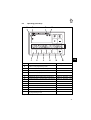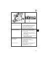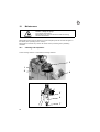
1
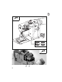
Contents
page:
Preface and general safety instructions
Part 1: Operating Manual, Class 768
1.
Product description . . . . . . . . . . . . . . . . . . . . . . . . . . . .
5
2.
Designated use . . . . . . . . . . . . . . . . . . . . . . . . . . . . . .
5
3.
Subclasses . . . . . . . . . . . . . . . . . . . . . . . . . . . . . . . . .
6
4.
Ancillary equipment
. . . . . . . . . . . . . . . . . . . . . . . . . . .
6
5.
Technical data . . . . . . . . . . . . . . . . . . . . . . . . . . . . . . .
6
6.
6.1
6.2
6.3
6.4
6.5
6.6
6.7
6.8
6.9
6.10
6.11
6.11.1
6.11.2
6.12
6.13
Operation . . . . . . . . . . . . . . . . . . . . . .
Threading the needle thread . . . . . . . . . . . .
Adjusting the needle-thread tension . . . . . . .
Opening the needle-thread tensioners . . . . . .
Adjusting the thread regulator . . . . . . . . . . .
Winding on the looper thread . . . . . . . . . . .
Fitting the looper-thread bobbin . . . . . . . . . .
Adjusting the looper-thread tension . . . . . . . .
Fitting and changing the needle . . . . . . . . . .
Raising the sewing feet . . . . . . . . . . . . . .
Locking the sewing feet in the up position . . . .
Adjusting the sewing-foot stroke . . . . . . . . .
Adjusting the sewing-foot stroke mechanically . .
Rapid electro-pneumatic stroke adjustment (HP)
Adjusting the sewing-foot pressure . . . . . . . .
Adjusting the stitch length . . . . . . . . . . . . .
.
.
.
.
.
.
.
.
.
.
.
.
.
.
.
.
9
9
9
9
10
11
12
13
14
15
15
16
16
17
18
18
7.
7.1
7.2
Keypad on sewing-machine arm . . . . . . . . . . . . . . . . . . . .
Keys . . . . . . . . . . . . . . . . . . . . . . . . . . . . . . . . . . . . .
LEDs . . . . . . . . . . . . . . . . . . . . . . . . . . . . . . . . . . . . .
19
19
19
Ausg./Edition: 07/99
.
.
.
.
.
.
.
.
.
.
.
.
.
.
.
.
.
.
.
.
.
.
.
.
.
.
.
.
.
.
.
.
.
.
.
.
.
.
.
.
.
.
.
.
.
.
.
.
.
.
.
.
.
.
.
.
.
.
.
.
.
.
.
.
.
.
.
.
.
.
.
.
.
.
.
.
.
.
.
.
.
.
.
.
.
.
.
.
.
.
.
.
.
.
.
.
.
.
.
.
.
.
.
.
.
.
.
.
.
.
.
.
.
.
.
.
.
.
.
.
.
.
.
.
.
.
.
.
.
.
.
.
.
.
.
.
.
.
.
.
.
.
.
.
.
.
.
.
.
.
.
.
.
.
.
.
.
.
.
.
.
.
.
.
.
.
.
.
.
.
.
.
.
.
.
.
GB
Contents
page:
8.
8.1
8.2
8.3
8.4
8.5
Control and operating panel . . .
General . . . . . . . . . . . . . . .
Operating-panel keys . . . . . . . .
Operating the V810 control unit . .
Changing parameter values . . . .
Direct parameter-number selection
.
.
.
.
.
.
.
.
.
.
.
.
.
.
.
.
.
.
.
.
.
.
.
.
.
.
.
.
.
.
.
.
.
.
.
.
.
.
.
.
.
.
.
.
.
.
.
.
.
.
.
.
.
.
.
.
.
.
.
.
.
.
.
.
.
.
.
.
.
.
.
.
.
.
.
.
.
.
.
.
.
.
.
.
.
.
.
.
.
.
.
.
.
.
.
.
.
.
.
.
.
.
.
.
.
.
.
.
.
.
.
.
.
.
20
20
21
22
23
23
9.
Sewing . . . . . . . . . . . . . . . . . . . . . . . . . . . . . . . . . . .
24
10.
10.1
10.2
Maintenance . . . . . . . . . . . . . . . . . . . . . . . . . . . . . . .
Cleaning and inspection . . . . . . . . . . . . . . . . . . . . . . . . .
Lubrication . . . . . . . . . . . . . . . . . . . . . . . . . . . . . . . . .
26
26
29
11.
11.1
Ancillary equipment . . . . . . . . . . . . . . . . . . . . . . . . . . .
Seam-centre guide . . . . . . . . . . . . . . . . . . . . . . . . . . . .
30
30
1.
Product description
The DÜRKOPP ADLER 768 is a special sewing machine with universal applications.
•
•
•
•
•
•
•
•
•
•
2.
Two-needle double-lockstitch pillar sewing machine with underfeed, needle feed
and alternating-foot overfeed
Robust design based on the proven modular system of the class 767.
Low-maintenance design (maintenance-free antifriction and sintering bearings,
articulated thread lever with permanently-lubricated roller bearings)
Automatic non-pressurised recirculating lubrication with sight glasses for oil level
and circulation. Shuttle lubrication must be carried out manually.
Maximum space beneath raised sewing feet: 16 mm.
Stroke of alternating sewing feet adjustable by adjusting wheel on arm up to a
maximum of 7 mm.
Large vertical shuttle with bobbin-housing lift.
A safety coupling on the lower toothed-belt wheel protects the shuttle from being
displaced or damaged if the thread jams in the shuttle track.
Fitted as standard with pedal-operated electro-pneumatic sewing-foot lift.
Fitted as standard with electro-pneumatic rapid stroke-adjustment with automatic
stitch rate limit, operated by knee switch or ergonomically-placed key on the
sewing-machine arm.
Automatic, infinitely-variable adjustment of stitch rates as a function of the stroke
height set.
GB
Designated use
The 768 is a special sewing machine designed for sewing heavy material. Such
material is generally made of textile fibres, but it may also be leather. It is used in the
clothing industry and for domestic and motor-vehicle upholstery.
This sewing machine can also be used to produce so-called technical seams. In this
case, however, the operator must assess the possible dangers which may arise (with
which DÜRKOPP ADLER AG would be happy to assist), since such applications are on
the one hand relatively unusual and, on the other, they are so varied that no single set
of criteria can cover them all. The outcome of this assessment may require appropriate
safety measures to be taken.
Generally only dry material may be sewn with this machine. The material may be no
thicker than 10 mm when compressed by the lowered sewing feet. The material may not
contain any hard objects, since if it does the machine may not be operated without an
eye-protection device. No such device is currently available.
The seam is generally produced with textile-fibre sewing thread of gauge 10/3 NeB
(cotton), 10/3 Nm (synthetic) or 10/4 Nm (covering yarn). Before using any other thread
the possible dangers arising must be assessed and appropriate safety measures taken
if necessary.
This special sewing machine may be set up and operated only in dry, well-maintained
premises. If the sewing machine is used in other premises which are not dry and
well-maintained it may be necessary to take further precautions (which should be
agreed in advance - see EN 60204-3-1: 1990).
As manufacturers of industrial sewing machines we proceed on the assumption that
personnel who work on our products will have received training at least sufficient to
acquaint them with all normal operations and with any hazards which these may involve.
5
3.
Subclasses
Class 768-274-FLP-HP: Two-needle double-lockstitch pillar sewing machine with
underfeed, needle feed and alternating-foot overfeed
4.
Ancillary equipment
order no.
ancillary equipment
9822 510125
light-guide sewing lamp
with mains cable and rocker switch, for fitting to the
sewing-machine arm
9880 767001
sewing-lamp fitting set
for light-guide sewing lamp 9822 510125
9822 510001
WALDMANN sewing lamp (halogen)
with 12V/20W bulb for fitting to the sewing-machine arm
0907 487519
sewing-lamp fitting set
for sewing lamp 9822 510001
0798 500088
230V sewing-light transformer
with mains cable, no switch,
for sewing lamps 9822 510001 and 9822510125
9781 000002
WE-6 filter controller
0797 003031
pneumatic connection set
For the pneumatic connection of frames with maintenance units and
pneumatic ancillary equipment. Consists of connection hose
(length 5 m, diameter 9 mm), hose nozzles, hose ties and
plug-and-socket connector.
No.depending tape guide with tape-roll holder
on tape width
N800 005611
5.
seam-centre guide
Technical data
Noise:
workplace emission value (DIN 45635-48-A-1-KL2)
Lc =
stitch length:
sewing-foot stroke:
stitch rate:
material:
85 dB (A)
9,6 mm
1,5 mm
1.400 min -1
4-play Skai, 1,6 mm 900 g/m 2
Lc =
stitch length:
sewing-foot stroke:
stitch rate:
material:
86 dB (A)
9,6
5,6 mm
1.400 min -1
4-play Skai, 1,6 mm 900 g/m 2
6
needle system:
134-35
needle thickness (depending on E No.):
- min.
- max.
- standard
[Nm]
[Nm]
[Nm]
140
200
180
needle gap (depending on E No.):
- min.
- max.
[mm]
[mm]
8
14
max. sewing-thread thicknesses:
- cotton
- synthetic thread
- covering yarn
[NeB]
[Nm]
[Nm]
10/3
10/3
10/3
[m]
[m]
approx. 22
approx. 35
max. stitch rate:
[rpm]
2400
max. stitch length:
- forwards:
- backwards:
[mm]
[mm]
12
12
max. material thickness:
[mm]
10
stroke height alternating sewing feet:
- max.
- ex works
[mm]
[mm]
7
1-6
feed stroke (above needle plate):
[mm]
1.2
max. passage beneath sewing feet:
- lift
[mm]
16
operating pressure:
[bar]
6
air consumption per working cycle (FLP and HP):
[NL]
approx. 0.2
sewing drive:
[type]
Efka DC1600/DA82GA
rated power:
[kW]
0.75
bobbin capacity:
- synthetic thread Nm 20/3:
- synthetic thread Nm 30/3:
rated voltage:
1 x 230 V, 50 / 60 Hz
frames:
[type]
MG55-3
dimensions (H x W x D):
[mm]
1570 x 1060 x 600
working height (ex works):
[mm]
950
[kg]
[kg]
approx. 56
approx. 46
weight:
- sewing-machine upper part
- frames with sewing drive
GB
7
1
2
3
8
Fig. a:
correct thread loop in the centre of
the material
Fig. b:
needle-thread tension too low
or looper-thread tension too great
Fig. c:
needle-thread tension too great
or looper-thread tension too low
6.
Operation
6.1
Threading the needle thread
Caution - danger of injury !
Turn off the main switch!
The needle thread may only be threaded with the sewing
machine switched off.
–
6.2
Thread the needle thread as shown in the illustration.
Adjusting the needle-thread tension
Pre-tensioners 1
The pre-tensioners 1 should be set at a lower tension than the main tensioners 3.
–
–
Adjust the pre-tensioners 1 by turning the knurled nuts.
After making major changes to the pre-tensioners 1, readjust the main tensioners 3.
Main tensioners 3
The main tensioners 3 should be set to the minimum possible tension.
The looping of the threads must be in the centre of the material (see fig. a).
With thin material excessive thread tension can cause unwanted gathering and thread
breakage.
–
GB
Adjust the main tensioner 2 so that the stitches are uniform.
Supplementary tensioner 2
The supplementary tensioner 2 can be switched in to effect a rapid change in
needle-thread tension during operation (e.g. with thickened seams, on the flap when
backstitching the front edge of a jacket or overcoat).
–
–
6.3
Set the supplementary tensioner 2 lower than the main tensioner.
The supplementary tensioner 2 is switched on during operation at the keypad on
the sewing-machine arm.
When the supplementary tensioner is switched on the LED over the relevant key
lights up.
Opening the needle-thread tensioners
The main tensioners 3 and supplementary tensioner 2, if it is switched on, open
automatically:
–
when the sewing feet are lifted electro-pneumatically (see section 6.9).
9
6.4
Adjusting the thread regulator
1
2
+
-
The thread regulator 1 regulates the amount of needle thread necessary for stitch
formation.
The setting depends on the following factors:
- material thickness
- yarn characteristics
- stitch length
A properly-adjusted thread regulator ensures an ideal sewing result at a minimum
needle-thread tension.
At the correct setting the needle-thread loop must slide at low tension over the thickest
point of the shuttle.
Caution - danger of injury!
Turn off the main switch.
The thread regulator may only be adjusted with the sewing
machine switched off.
–
–
Undo both screws 2.
–
Tighten screws 2.
10
Move the thread regulator 1.
The thread regulator is fitted with slots for this purpose.
Moving in the "+" direction increases the quantity of needle thread
Moving in the "-" direction reduces the quantity of needle thread
6.5
Winding on the looper thread
1
2
E
B
C
3
Caution - danger of injury !
Turn off the main switch.
The looper thread may be threaded for spooling only with
the sewing machine switched off.
The looper thread may be spooled only with the sewing
feet locked in the raised position.
–
If spooling is to take place when sewing with no underlaid material:
lock the sewing feet in the raised position (see section 6.9).
–
–
–
–
–
Thread the looper thread as shown in the illustration.
–
GB
Wind about 5 loops of the looper thread anti-clockwise onto the bobbin core.
Place the bobbin on bobbin-winder shaft 2.
Swivel bobbin-winder lever 3 against the bobbin.
Adjust tension 1.
The looper thread should be wound on with minimal tension.
Sew.
The bobbin-winder lever 3 terminates the process as soon as the bobbin is full.
11
6.6
Fitting the looper-thread bobbin
4
2
1
2
5
6
7
3
Caution - danger of injury!
Turn off the main switch.
The looper-thread bobbin may only be changed with the sewing machine switched off.
Removing the empty looper-thread bobbin
–
–
–
–
–
Raise the sewing foot.
Open shuttle cover 3.
Raise bobbin-housing flap 1.
Remove upper part of bobbin-housing 2.
Remove empty looper-thread bobbin.
Threading looper thread
–
Place full bobbin 4 in the upper part of bobbin-housing 2:
When the thread is unwound the bobbin must rotate in the opposite direction
(see arrow).
–
–
–
–
–
–
Draw looper thread through slit 5 beneath tensioning spring 6.
12
Thread looper thread through hole 7 in the upper part of bobbin-housing 2.
Trim looper thread to approx. 3 cm.
Insert upper part of bobbin-housing 2 with full bobbin into the shuttle.
Close bobbin-housing flap 1.
Close shuttle cover 3.
6.7
Adjusting the looper-thread tension
1
3
2
2
3
Caution - danger of injury!
Turn off the main switch.
The looper-thread tension may only be adjusted with the sewing machine switched off.
Adjusting the tensioning spring 2
–
–
–
Open the shuttle cover.
Adjust the tensioning spring 2 with regulating screw 3.
to increase looper-thread tension =
turn screw 3 clockwise
to decrease looper-thread tension =
turn screw 3 anti-clockwise
Close shuttle cover.
13
GB
6.8
Fitting and changing the needle
1
2
3
4
Caution - danger of injury!
Turn off the main switch.
Needles may only be changed with the sewing machine
switched off.
–
–
–
–
Turn the handwheel until the needle rod 1 has reached its highest point.
–
Tighten screw 3.
Undo screw 3.
Withdraw needle downwards from needle holder 2.
Insert new needle as far as it will go into the hole in needle holder 2.
Caution:
When seen from the operating side of the machine the furrow 4 of the right-hand
needle must point to the right and the furrow of the left-hand needle to the left
(see sketch).
CAUTION:
When a thicker needle is fitted the distance from the
shuttle to the needle must be corrected
(see servicing instructions).
Failure to comply with this instruction can cause the following faults:
when fitting a thinner needle:
-faulty stitches
-damage to thread
when fitting a thicker needle:
-damage to the shuttle tip
-damage to the needle
14
6.9
Raising the sewing feet
The class 768 pillar sewing machine is fitted with the electro-pneumatic sewing-foot lift
(FLP) as standard. This enables the sewing feet to be raised during sewing.
–
–
–
–
Push pedal half-way back.
The sewing machine halts in the 1st position (needles down).
Raising the sewing feet.
Release pedal.
Push pedal forwards.
The sewing machine begins sewing at the rate set by the pedal.
6.10
Locking the sewing feet in the up position
GB
1
The electro-pneumatically raised sewing feet are locked in the up position with the
lever 1 (e.g. to spool the looper thread or change the sewing feet).
The lever 1 is located at the rear of the sewing-machine arm.
–
With the machine at a halt push the pedal half-way back.
Raising the sewing feet.
–
Swivel lever 1 down.
The sewing feet are locked in the up position.
–
Swivel lever 1 up.
The sewing feet are no longer locked.
15
6.11
Adjusting the sewing-foot stroke
1
E
B
C
6.11.1
Adjusting the sewing-foot stroke mechanically
The height of the sewing-foot stroke is adjusted with adjusting wheel 1 on the arm cover.
Caution - danger of injury
The sewing-foot stroke may only be adjusted with
the sewing machine switched off.
–
Turn adjusting wheel 1. min., A, B, C, D, E, F, max.
min.
= minimum sewing-foot stroke
max.
= maximum sewing-foot stroke
Automatic stitch rate limit
The sewing-foot stroke and stitch rate are mutually dependent (see table).
A potentiometer is mechanically connected to adjusting wheel 1. The control system
registers the set sewing-foot stroke via this potentiometer and limits the stitch rate.
stitch-length range
[mm]
0-8
8 - 12
16
adjusting cam
[position]
min.
A
B
C
D
E
F
max.
min. - max.
sewing-foot
stroke [mm]
1.5
2.4
3.3
4.2
5.1
6.0
max. stitch rate
[rpm]
2400
2350
2200
2050
1950
1750
1650
1600
1600
6.11.2
Rapid electro-pneumatic stroke adjustment (HP)
2
1
The class 768 pillar sewing machine is fitted with rapid electro-pneumatic stroke
adjustment (HP) as standard.
Maximum sewing-foot stroke can be activated while sewing for additional thicknesses in
the material or to oversew cross-seams as follows:
–
Press keypad key 1 on the sewing-machine arm.
OR:
–
Operate knee-switch 2 beneath the table plate.
GB
Rapid stroke adjustment: operating mode
How long maximum sewing-foot stroke remains active depends on which operating
mode has been set. Three operating modes are available.
They are set with parameters F-138 and F-184 on the operating panel
(see motor-manufacturer’s guide (supplied)).
Operating
mode
Operation / Explanation
Press and
hold
F-138 = off
F-184 = 0
Maximum sewing-foot stroke remains active for as long as key 1
or knee-switch 2 is pressed.
Press and
release
F-138 = on
Maximum sewing-foot stroke is activated by pressing key 1 or
knee-switch 2.
Pressing the key or knee-switch again deactivates maximum
sewing-foot stroke again.
Press and
hold with
minimum
stitch rate
F-138 = off
F-184 > 0
Maximum sewing-foot stroke remains active for as long as key 1
or knee-switch 2 is pressed.
After the key or knee-switch is released the machine continues
sewing until the pre-set minimum stitch rate (parameter F-184) is
reached with maximum sewing-foot stroke. The seam is then
continued at normal sewing-foot stroke.
17
6.12
Adjusting the sewing-foot pressure
E
B
C
2
3
1
The sewing-foot pressure is adjusted with knob 1.
–
to increase sewing-foot pressure = turn knob 1 clockwise
to decrease sewing-foot pressure = turn knob 1 anti-clockwise
6.13
Adjusting the stitch length
The stitch length is adjusted with knob 2.
–
to increase stitch length = turn knob 2 clockwise
to decrease stitch length = turn knob 2 anti-clockwise
–
To sew bar-tacks manually press stitch-regulating lever 3 down.
The machine sews backwards for as long as the stitch-regulating lever 3 is held
down.
The stitch length is the same as that set for sewing forwards.
See also section 8.
NB:
With stitch lengths over 8 mm the speed of rotation of the sewing drive is automatically
reduced.
This is to avoid overloading the stitch-setting transmission.
18
7.
Keypad on the sewing-machine arm
1
5
7.1
2
6
3
7
4
8
Keys
key
function
5
position needle in up or down position (stitch by stitch)
6
activate maximum sewing-foot stroke
7
switch additional thread tension on/off
8
switch seam-centre guide stop on/off
7.2
GB
LED
LED
display
1
maximum sewing-foot stroke activated
2
sewing drive switched on
3
additional thread tension switched on
4
switch seam-centre guide stop switched on
19
8.
Control and operating panel
CAUTION!
This manual covers only those key functions and parameter changes available to the operator.
For a more detailed description of the control system please consult the motor-manufacturer’s current operating manual (supplied).
8.1
General
The operating panel is used to program the control unit and to set seam functions.
Depending on the nature of the job, sewing may be executed manually or by seam
programming.
For differing jobs seams can be programmed for which the functions (starting bar tack,
ending bar tack, stitch count, thread cutting etc.) and parameter values
(stitch rate, seam length, rpm etc.) are individually assigned.
Entry is carried out in programming mode.
The parameters and the values assigned are displayed.
The seam programs are not lost even when the sewing machine is switched off
(battery buffer).
In order to avoid the inadvertent alteration of pre-set functions, operation is divided into
various levels (operator, technician, fitter).
The operator (seamstress) can program directly.
On the other levels access is contingent on the entry of a code number (EFKA).
RESET
If the control unit is hopelessly misadjusted, this function allows the technician to reset
all adjusted values to their default (ex-works) settings.
This function is described in the Servicing instructions!
20
8.2
Operating-panel keys
C
D
1
key
E
2
3
F
4
function
A
GB
B
settings
P
start or end programming mode
E
confirm a parameter-value change
+
increase a displayed parameter value
-
decrease a displayed parameter value
1*
starting bar tack or starting-stitch compression
2*
ending bar tack or ending-stitch compression
SINGLE / DOUBLE / OFF
3
auto foot lift on stop in mid-seam
ON / OFF
auto foot lift after thread cut-off
ON / OFF
4
basic needle position (UT/OT)
POSITION 1/POSITION 2
A*
key for bar-tack suppression or activation
B
key for needle up/down or shift-key
in programming mode
SINGLE / DOUBLE / OFF
* key function vacant on this machine class
21
Symbol
C
8.3
function
automatic rotation speed active
D
light barrier switched on
E
machine running
F
limited rotation speed active
Operating the V810 control unit
Functions can be switched on and off by pressing the number keys and certain and
symbol keys on the control panel.
key 3: auto foot lift
auto foot lift on stop in mid-seam on:
auto foot lift on stop in mid-seam off:
auto foot lift after thread cut-off on:
auto foot lift after thread cut-off off:
right arrow over key 3 on.
right arrow off.
left arrow over key 3 on.
left arrow off.
key 4: basic needle position
basic needle position UT:
basic needle position OT:
left arrow over key 4 on.
left arrow off.
22
8.4
Changing parameter values
CAUTION!
After changing parameters it is essential to carry out a sewing run. Only then is the altered setting properly saved. If
sewing does not take place, the new setting is lost when
the main switch is turned off.
Parameters are changed and switched on and off with the "P", "E", "+" and "-" keys on
the operating panel.
The parameters which can be changed at operator level are listed below.
1.
Switch on mains.
2.
Start programming mode
–
Press the "P" key.
The last parameter to have been called appears. If no parameter has been called
since the main switch was turned on, "F - 000" appears in the display.
3.
Select required parameter
–
Press the "+" or "-" key repeatedly until the required parameter appears in the
display. If the "+" or "-" key is held down, the parameter number automatically
cycles until the key is released.
–
Pressing the "E" key displays the parameter value.
GB
4.
Change displayed parameters
–
Press the "+" or "-" keys to change the value of the parameter or switch its
function on and off.
5.
Save change parameter values
–
Press the "E" key to change further parameter values.
The changed parameter value is saved. The next operator-level parameter
appears in the display.
or:
–
Press the "P" key to leave programming mode.
The last parameter value to have been changed is saved.
The control system leaves programming mode.
–
Commencing sewing saves the new values, which are thus preserved when the
machine is switched off.
8.5
Direct parameter-number selection
The parameter number can also be selected directly:
–
When a parameter number is displayed, press the ">>" key.
The first character flashes.
–
Move to the next character by pressing the "+" or "-" keys.
23
9.
Sewing
The description of the sewing process is based on the following assumption:
–
The machine in question is a special sewing machine of sub-class
768-274-FLP-HP.
–
The following functions are set on the operating panel:
stitch counting:
basic needle position:
auto sewing-foot lift on stop in mid-seam:
starting bar-tack:
ending bar-tack:
thread cutter
–
OFF
DOWN (position 1)
OFF
OFF
OFF
THREAD CUTTER +
RETURN
Main switch on.
Operating and function sequence for sewing:
Sewing process
Operation / Explanation
Before starting to sew
Initial position
- Pedal in rest position.
Sewing machine at a standstill.
Needle up. Sewing feet down.
Position the material
at the start of the seam
- Push pedal half-way back.
The sewing feet rise.
- Press material against the needles.
Sewing
- Push pedal forwards and hold it there.
The machine sews at the speed determined
by the pedal.
In mid-seam
- Release pedal (rest position).
The machine halts in the 1st position
(needle down).
The sewing feet are down.
Interrupting the sewing process
Continuing the sewing process
(after releasing the pedal)
24
- Push the pedal forwards.
The machine sews at the speed determined
by the pedal.
E
B
C
1
Sewing intermediate bar-tacks
2
- Press stitch-regulating lever 1 downwards.
The machine sews backwards for as long as
the stitch-regulating lever is held down.
Speed is determined by the pedal.
- Press key 2 or operate the knee-switch.
Oversewing a cross-seam.
(maximum sewing-foot stroke)
Maximum sewing-foot stroke is activated.
The rotation speed is limited to 1600 rpm.
- Maximum sewing-foot stroke operating modes:
a) Press and hold
Hold key or knee-switch pressed for as
long as maximum sewing-foot stroke is to
remain active.
b) Press and release
Briefly press key or knee-switch to activate
maximum sewing-foot stroke.
Press it again to deactivate it.
At the seam end
remove material
- Push pedal fully back and hold.
The machine halts in the 2nd position.
The needles are up.
The sewing feet rise.
- Remove material.
do not lift sewing feet
- Briefly push pedal fully forwards and release.
The machine halts in the 2nd position.
The needles are up.
The sewing feet remain lowered.
25
GB
10.
Maintenance
Caution - danger of injury!
Turn off the main switch!
Maintenance may only be carried out with the sewing
machine switched off.
Maintenance work must be carried out no less frequently than at the intervals given in
the tables (see "operating hours" column).
Maintenance intervals may need to be shorter when processing heavy-shedding
materials.
10.1
Cleaning and inspection
A clean sewing machine is a trouble-free sewing machine!
3
1
2
4
6
4
8
2
10
5
6
7
26
maintenance work
to be carried out
explanation
operating
hours
Upper part of machine
- Remove lint, pieces of
thread and other debris.
Places in special need of cleaning:
- area under the needle plate
- feeders
- area around the shuttle 2
- upper part of bobbin housing 3
- inner surface of shuttle cover
- needle-thread tensioners
8
- Clean oil collector.
- Remove lint and oil spills with a cloth
8
Sewing drive
- Check the condition and
tension of the V-belt.
It must be possible to depress the V-belt
by about 10 mm by pressing it with a
finger at its mid-point.
160
The water level must not rise as high as
the filter insert 5.
- After screwing in the drain screw 7
blast water under pressure out of the
water separator 6.
40
Compressed-air
maintenance unit
(ancillary equipment)
- Check the water level
in the pressure regulator.
GB
NB:
The water separator 6 is fitted with
semi-automatic condensation drainage.
When the pressure falls below a certain
level the condensation is automatically
drained.
Clean the filter insert.
Dirt and condensation are separated out
by the filter insert 5.
- Disconnect the machine from the
compressed-air supply.
- Screw in drain screw 7.
There must be no pressure in the
machine’s pneumatic system.
- Unscrew water separator 6.
- Unscrew filter insert 5
Wash the filter shell and insert
with cleaning fluid (not solvent)
and blast clean.
- Re-assemble and connect the
maintenance unit.
500
27
1
E
B
C
2
3
4
28
5
10.2
Lubrication
Caution - danger of injury!
Oil can cause skin eruptions.
Avoid protracted contact with the skin.
In the event of contact, thoroughly wash the affected area.
CAUTION!
The handling and disposal of mineral oils is subject to legal
regulation.
Deliver used oil to an authorised collection point.
Protect your environment.
Take care not to spill oil.
To lubricate the special sewing machine use only ESSO SP-NK 10 lubricating oil
or an equivalent oil of the following specification:
–
–
viscosity at 40° C :
flashpoint:
10 mm2/s
150 °C
ESSO SP-NK 10 is available from DÜRKOPP-ADLER AG retail outlets under the
following part numbers:
2-litre container:
9047 000013
5-litre container:
9047 000014
GB
maintenance work
to be carried out
explanation
operating
hours
- Lubricating the sewing
head and the lower part of
the sewing machine.
Remove stopper 1.
- Top up with oil.
- Check the oil level at the sight glass 3.
The oil level must always be above
the red "full" line.
- Replace stopper 1.
- Remove any oil spillage from the oil
collector.
8
- Lubricating the shuttle.
- Use the oil can (in the accessory pack)
to drip a few drops of oil into hole 4 in
the shuttle-plunger ring 5
(there is no recirculation lubrication)
3
- Inspecting the oil supply
to the sewing head.
- Inspect the oil supply
during operation at the viewing
window 2.
- if no oil flow is visible at the viewing
window, inform the service technician.
8
29
11.
Ancillary equipment
11.1
Seam-centre guide (only if 768-E2/... is present)
General
The seam-centre guide provides guidance when backstitching. The function of the
guide piece is to ensure that there is an equal distance between the centre of the seam
and the left and right-hand needles.
Bearing pressure of seam-centre guide stop
CAUTION!
The seam-centre guide pressure must not exceed a maximum of 2 bar!
–
To adjust the bearing pressure, pull out and rotate the pressure-regulator handle.
clockwise
anti- clockwise
30
=
=
to increase pressure
to decrease pressure