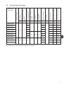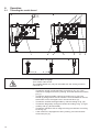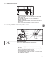
1
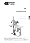
888
Spezialnähmaschine
Betriebsanleitung
D
Instruction manual
GB
Postfach 17 03 51, D-33703 Bielefeld • Potsdamer Straße 190, D-33719 Bielefeld
Telefon +49 (0) 521 / 9 25-00 • Telefax +49 (0) 521 / 9 25 24 35 • www.duerkopp-adler.com
Ausgabe / Edition:
02/2009
Änderungsindex
Rev. index: 03.0
Printed in Federal Republic of Germany
Teile-Nr./Part.-No.:
0791 888740
Alle Rechte vorbehalten.
Eigentum der Dürkopp Adler AG und urheberrechtlich geschützt. Jede, auch auszugsweise Wiederverwendung
dieser Inhalte ist ohne vorheriges schriftliches Einverständnis der Dürkopp Adler AG verboten.
All rights reserved.
Property of Dürkopp Adler AG and copyrighted. Reproduction or publication of the content in any manner, even
in extracts, without prior written permission of Dürkopp Adler AG, is prohibited.
Copyright © Dürkopp Adler AG - 2009
Foreword
This instruction manual is intended to help the user to become familiar
with the machine and take advantage of its application possibilities in
accordance with the recommendations.
The instruction manual contains important information on how to
operate the machine securely, properly and economically. Observation
of the instructions eliminates danger, reduces costs for repair and
down-times, and increases the reliability and life of the machine.
The instruction manual is intended to complement existing national
accident prevention and environment protection regulations.
The instruction manual must always be available at the machine/sewing
unit.
The instruction manual must be read and applied by any person that is
authorized to work on the machine/sewing unit. This means:
–
–
–
Operation, including equipping, troubleshooting during the work
cycle, removing of fabric waste,
Service (maintenance, inspection, repair) and/or
Transport.
The user also has to assure that only authorized personnel work on the
machine.
The user is obliged to check the machine at least once per shift for
apparent damages and to immediatly report any changes (including the
performance in service), which impair the safety.
The user company must ensure that the machine is only operated in
perfect working order.
Never remove or disable any safety devices.
If safety devices need to be removed for equipping, repairing or
maintaining, the safety devices must be remounted directly after
completion of the maintenance and repair work.
Unauthorized modification of the machine rules out liability of the
manufacturer for damage resulting from this.
Observe all safety and danger recommendations on the machine/unit!
The yellow-and-black striped surfaces designate permanend danger
areas, eg danger of squashing, cutting, shearing or collision.
Besides the recommendations in this instruction manual also observe
the general safety and accident prevention regulations!
General safety instructions
The non-observance of the following safety instructions can cause
bodily injuries or damages to the machine.
1. The machine must only be commissioned in full knowledge of the
instruction book and operated by persons with appropriate training.
2. Before putting into service also read the safety rules and
instructions of the motor supplier.
3. The machine must be used only for the purpose intended. Use of
the machine without the safety devices is not permitted. Observe all
the relevant safety regulations.
4. When gauge parts are exchanged (e.g. needle, presser foot, needle
plate, feed dog and bobbin) when threading, when the workplace is
left, and during service work, the machine must be disconnected
from the mains by switching off the master switch or disconnecting
the mains plug.
5. Daily servicing work must be carried out only by appropriately
trained persons.
6. Repairs, conversion and special maintenance work must only be
carried out by technicians or persons with appropriate training.
7. For service or repair work on pneumatic systems, disconnect the
machine from the compressed air supply system (max. 7-10 bar).
Before disconnecting, reduce the pressure of the maintenance unit.
Exceptions to this are only adjustments and functions checks made
by appropriately trained technicians.
8. Work on the electrical equipment must be carried out only by
electricians or appropriately trained persons.
9. Work on parts and systems under electric current is not permitted,
except as specified in regulations DIN VDE 0105.
10. Conversion or changes to the machine must be authorized by us
and made only in adherence to all safety regulations.
11. For repairs, only replacement parts approved by us must be used.
12. Commissioning of the sewing head is prohibited until such time as
the entire sewing unit is found to comply with EC directives.
13. The line cord should be equipped with a country-specific mains
plug. This work must be carried out by appropriately trained
technicians (see paragraph 8).
It is absolutely necessary to respect the safety
instructions marked by these signs.
Danger of bodily injuries !
Please note also the general safety instructions.
Table of contents
page:
Introduction and safety instructions
Part 1: Operating Instructions Class 888
(Edition 02/2009)
1.
Product description
. . . . . . . . . . . . . . . . . . . . . . . . . . . . . . . . . . . . . . . . . . .
5
2.
Designated use . . . . . . . . . . . . . . . . . . . . . . . . . . . . . . . . . . . . . . . . . . . . . .
5
3.
3.1
3.2
Subclasses and sewing equipment
Subclasses . . . . . . . . . . . . . . . . . . . . . . . . . . . . . . . . . . . . . . . . . . . . . . . . . .
Sewing equipment. . . . . . . . . . . . . . . . . . . . . . . . . . . . . . . . . . . . . . . . . . . . . .
6
7
4.
Optional equipment . . . . . . . . . . . . . . . . . . . . . . . . . . . . . . . . . . . . . . . . . . . .
9
5.
5.1
5.2
Technical data
Technical data class . . . . . . . . . . . . . . . . . . . . . . . . . . . . . . . . . . . . . . . . . . . .
Technical data subclasses . . . . . . . . . . . . . . . . . . . . . . . . . . . . . . . . . . . . . . . . .
10
10
6.
6.1
6.2
6.3
6.4
6.4.1
6.4.2
6.5
6.5.1
Operation
Threading the needle thread . . . . . . . . . . . . . . . . . . . . . . . . . . . . . . . . . . .
Winding the hook thread . . . . . . . . . . . . . . . . . . . . . . . . . . . . . . . . . . . . . .
Bobbin insertion and threading the hook thread . . . . . . . . . . . . . . . . . . . . . . .
Adjusting the thread tension . . . . . . . . . . . . . . . . . . . . . . . . . . . . . . . . . . . .
Adjusting the hook thread tension . . . . . . . . . . . . . . . . . . . . . . . . . . . . . . . .
Adjusting the needle thread tension . . . . . . . . . . . . . . . . . . . . . . . . . . . . . . .
Switching on/off the thread tensioners . . . . . . . . . . . . . . . . . . . . . . . . . . . . .
Function of the thread main tension and the thread supplementary tension in relation
to the sewing foot lifting . . . . . . . . . . . . . . . . . . . . . . . . . . . . . . . . . . . . . .
Adjusting the thread regulator. . . . . . . . . . . . . . . . . . . . . . . . . . . . . . . . . . .
Changing the needle with single-needle machines with the hook on the right . . . . . .
Changing the needle with single-needle machines with the hook on the left
(machine with lower thread trimmer) . . . . . . . . . . . . . . . . . . . . . . . . . . . . . . .
Changing the needle with double-needle machines . . . . . . . . . . . . . . . . . . . . .
Lifting and folding the roller presser . . . . . . . . . . . . . . . . . . . . . . . . . . . . . . .
Sewing-foot pressure . . . . . . . . . . . . . . . . . . . . . . . . . . . . . . . . . . . . . . . .
Setting through the setting wheel. . . . . . . . . . . . . . . . . . . . . . . . . . . . . . . . .
Constant sewing-foot pressure through the cylinder . . . . . . . . . . . . . . . . . . . . .
Sewing backward (feeding backward; backtacking). . . . . . . . . . . . . . . . . . . . . .
Setting the stitch length . . . . . . . . . . . . . . . . . . . . . . . . . . . . . . . . . . . . . .
Switching on the safety clutch at the hook blocking . . . . . . . . . . . . . . . . . . . . . .
Starting the manually controlled machine with the clutch motor . . . . . . . . . . . . . .
Operating the machine equipped with the positioning motor . . . . . . . . . . . . . . . .
Using the pedal . . . . . . . . . . . . . . . . . . . . . . . . . . . . . . . . . . . . . . . . . . .
Using the key. . . . . . . . . . . . . . . . . . . . . . . . . . . . . . . . . . . . . . . . . . . . .
6.6
6.7
6.8
6.9
6.10
6.11
6.11.1
6.11.2
6.12
6.13
6.14
6.15
6.16
6.16.1
6.16.2
.
.
.
.
.
.
.
.
.
.
.
.
.
.
.
.
.
.
.
.
.
12
13
13
14
14
16
18
. . . .
. . . .
. . . .
19
20
21
.
.
.
.
.
.
.
.
.
.
.
.
.
22
23
24
25
25
26
26
27
28
29
29
30
31
.
.
.
.
.
.
.
.
.
.
.
.
.
.
.
.
.
.
.
.
.
.
.
.
.
.
.
.
.
.
.
.
.
.
.
.
.
.
.
.
.
.
.
.
.
.
GB
Contents
page:
6.17
6.17.1
6.17.2
6.17.3
Material edge trimmer control .
Switching on/off edge trimmer
Switching on/off material guide
Material guide adjustment . . .
.
.
.
.
.
.
.
.
.
.
.
.
.
.
.
.
.
.
.
.
.
.
.
.
.
.
.
.
.
.
.
.
.
.
.
.
.
.
.
.
.
.
.
.
.
.
.
.
.
.
.
.
.
.
.
.
.
.
.
.
.
.
.
.
.
.
.
.
.
.
.
.
.
.
.
.
.
.
.
.
.
.
.
.
.
.
.
.
.
.
.
.
.
.
.
.
.
.
.
.
.
.
.
.
.
.
.
.
.
.
.
.
.
.
.
.
.
.
.
.
.
.
.
.
.
.
.
.
.
.
.
.
.
.
.
.
.
.
.
.
.
.
.
.
.
.
.
.
.
.
.
.
33
33
34
35
7.
Positioning drive Efka DC1550/DA321G . . . . . . . . . . . . . . . . . . . . . . . . . . . . . . .
35
8.
8.1
8.2
Sewing with machine equipped with positioning motor
Machine automatic function . . . . . . . . . . . . . . . . . . . . . . . . . . . . . . . . . . . . . . . .
Example of machine operation at sewing . . . . . . . . . . . . . . . . . . . . . . . . . . . . . . .
37
38
9.
9.1
9.2
Maintenance
Cleaning and checking . . . . . . . . . . . . . . . . . . . . . . . . . . . . . . . . . . . . . . . . . .
Lubrication . . . . . . . . . . . . . . . . . . . . . . . . . . . . . . . . . . . . . . . . . . . . . . . . . .
38
42
1.
Product description
The Dürkopp Adler 888 is a special sewing machine for universal use.
2.
•
•
It is a double lockstitch post bed sewing machine .
•
Depending on subclass, the machine is either single needle or
double needle unit with automatic functions such as thread
trimming, automatic backtacking, automatic foot lifting, or without
them.
•
The single needle machine can be equipped with edge trimming
with a hook post to the left of the needle.
•
•
•
•
The machine is equipped with a large two part vertical hook.
•
The throat plate has replaceable inserts with the stitch hole
dimension difference, which are optional in dependence on the
needle number.
•
The machine has automatic wick lubrication from the central oil tank
with a visual check of the oil level by oil level indicator in the
machine arm. The part of the oil with which the hook is lubricated is
devaluated. The other part of the lubrication oil is returned to the
central tank by a pump.
•
Integrated bobbin winder.
It has a two step feed. A lower wheel feeder and a driven roller
presser feed in two steps, a needle feed feeds in the first step only.
In single needle machines, the first step represents 50% of the total
stitch length; in double needle machines it represents 30%.
Maximum foot lift is 12 mm.
The residual thread length after thread trimming is about 15 mm.
The hook is protected with a safety clutch against the
disarrangement of the adjusted position at the blocking of the
thread which interfered with its way.
GB
Designated use
The class 888 is designated for sewing shoe, leather, and upholstery
sewing. In general, the material sewn is leather (natural or artificial).
It is possible to use it for shoe fabrics too.
The equipment for light, medium or heavy sewing is mounted on the
machine as an option.
The subclass with material trimming is designated especially for the
shoe lining trimming if the lining has the corresponding strength. The
cutting mechanism allows the lining trimming under the leather surface
layer. It is possible to trim also all sewn layers.
It is possible to sew dry material only which may not be thicker than 7
mm when pressed down with a roller presser. The material may not
contain hard objects, as the machine is not equipped with an eye
guard. This machine may be operated in dry rooms and by a trained
person only who is aware of the risks described in this instruction.
This special sewing machine may be set up and operated only
in dry, well-maintained premises. If the sewing machine is used in
premises which are not dry and well-maintained it may be
necessary to take further precautions (which should be agreed in
advance - see EN 60204-31:1999).
5
As manufacturers of industrial sewing machines we proceed on the
assumption that personnel who work on our products will have
received training at least sufficient to acquaint them with all normal
operations and with any hazards which these may involve.
6
0888 160020
X
X
X
0888 160122
X
X
X
X
0888 160152
X
X
X
X
0888 160522
X
X
X
0888 260020
X
X
X
0888 260122
X
X
X
0888 260522
X
X
X
X
X
X
X
X
X
X
X
X
X
X
X
X
X
0888 356122
X
X
X
X
0888 356152
X
X
X
X
X
X
X
X
0888 356020
Trimming
and
backtacking
with trimming,
automatic backtacking
Hook
without trimming,
manual backtacking
Machine
control
manual
lower trimming to the
right of the needle
Material
trimming
without trimming
up to 7 mm
up to 5 mm
Stitch
length
1 needle, hook to the left
of the needle
2 needles
Needle
number
1 needle, hook to the
right
of the needle
Class and
subclasses
standard
Subclasses
big, two parts
3.1
automatic foot lifting and
pneumatic backtacking
Subclasses and sewing equipment
automatic foot lifting
and electric backtacking
3.
X
X
X
X
X
X
X
X
X
X
X
888-E2
888-E3
0888 356122
888-E7/1,5
0888 356020
888-E6/1,2
1/min
1/min
70-80
70
80-60
60
4
3000
2500
mm
mm
mm
mm
-
-
-
-
-
-
-
0,8
-
1,0
-
1,2
-
1,5
1,2
-
1,6
-
2,0
-
1,6
-
2,0
-
5
2,4
-
4
2,0
-
2,4
-
3,2
-
-
-
-
-
-
-
Noise **
mm
Trimming distance from the
needle
Standard *
-
Seam distance
Maximum
-
Wheel feed tooth pitch
Maximum stitch length
0,01
mm
Top roller diameter
Standard
Sewing speed
Scope
Polyester
thread label
number
Needle number
Standard
0,01
mm
dB
(A)
0,6
1
888-E4/0,8
888-E5/1,0
Sewing category
light
Scope
0888 160020
0888 160122
0888 160522
888-E1
Number of needles
For classes and subclasses
Sewing equipment
Sewing equipment
3.2
medium
90-110
90
50-30
40
5
2500
2500
heavy
***
120-160
120
25-10
20
7
2000
1600
light
70-80
70
80-60
60
4
3000
2500
medium
90-110
90
50-30
40
5
2500
2500
1
35
1,2
25
heavy
120-160
120
25-10
20
5
2000
0,6
888-E8/1,2
light
888-E9/1,6
70-80
70
80-60
60
4
3000
GB
1600
2500
888-E10/2,0
888-E11/1,6
888-E12/2,0
888-E13/2,4
0888 260020
0888 260122
0888 260522
0,6
4
2
medium
90-110
90
50-30
40
888-E14/2,0
888-E15/2,4
heavy
120-160
120
25-10
20
888-E17
888-E19
888-E22
*
5
2500
2000
2000
35
1600
1,2
5
0888 160020
0888 160122
0888 160522
888-E16/3,2
4
25
1
medium
90-110
90
50-30
40
5
2500
2500
1,2
25
0,6
25
When sewing very thick layers, it is necessary to reduce the sewing speed significantly; at the parallel sewing
and trimming too.
** Acoustic pressure level of a separate machine in the workplace.
Measured at the maximum stitch length and maximum sewing speed in compliance with DIN 45635-48-A-1-KL2.
*** A pneumatically controlled machine 0888 160522 can have a needle No. 200.
7
888-E20/2,0
888-E21/2,4
medium
2
888-E24
888-E25
888-E26/0,8
888-E27/1,0
888-E28/1,2
888-E29/1,5
*
0888 356152
888-E23
0888 160152
888-E30/1,6
light
-
mm
min
min
-1
0,01
mm
mm
90-110
90
4
25
120-160
120
5
35
mm
mm
mm
1,6
-
2,0
-
35
2,4
-
35
1,6
-
-
-
-
-
-
-
-
0,8
-
1,0
-
1,2
-
1,5
Noise **
Trimming distance from the needle
Seam distance
Wheel feed tooth pitch
Standard *
Top roller diameter
Sewing speed
Maximum
Maximum stitch length
Standard
Scope
Polyester
thread label
number
Needle number
Standard
Scope
Sewing category
Number of needles
For classes and subclasses
0888 260020
0888 260122
0888 260522
Sewing equipment
888-E18/1,6
-
-1
0,01
mm
dB
(A)
1,2
120-160
120
90-110
90
70-80
70
50-30
40
5
2500
2500
4
80-60
60
4
3000
2500
0,6
1
medium
90-110
90
50-30
40
5
2500
2500
heavy
120-160
120
25-10
20
7
2000
1600
light
70-80
70
80-60
60
4
2000
medium
90-100
90
50-30
40
5
2500
25
1,2
25
1
heavy
120-160
120
25-10
20
5
2000
1600
0,6
When sewing very thick layers, it is necessary to reduce the sewing speed significantly; at the parallel sewing
and trimming too.
** Acoustic pressure level of a separate machine in the workplace.
Measured at the maximum stitch length and maximum sewing speed in compliance with DIN 45635-48-A-1-KL2.
8
4.
Optional equipment
Order number
Optional equipment
0888 220334
Roller presser Æ 25 mm knurled
0888 220344
Roller presser Æ 25 mm smooth
0888 220354
Roller presser Æ 25 mm rubberized
0888 220364
Roller presser Æ 35 mm knurled (basic)
0888 220374
Roller presser Æ 35 mm smooth
0888 220384
Roller presser Æ 35 mm rubberized
0888 220394
Roller presser Æ 45 mm, width 3.8 mm
0888 220404
Roller presser Æ 45 mm, width 2.0 mm
9880 888100
Diode lamp
MG55 400334
Stand set MG55-3 for the machine driven with a V-belt
(contains a frame, pedal, drawer and a table top 1060 x 500 mm)
MG55 400324
Stand set MG55-3 for the machine driven with a toothed belt
(contains a frame, pedal, drawer and a table top 1060 x 50 mm)
0700 088802
Stand top plate for the V-belt
0700 088804
Stand top plate for the toothed belt
N800 080030
Edge-guide, swivelling
N800 080004
Roller stop
9805 791113
USB memory key for data transmission to Efka DA321G drive control
0867 490010
Efka V810 or V820 control panel bracket
0688 130384
Knee lever for mechanical foot lifting
9780 000108
WE-8 maintenance unit for pneumatic optional equipments
0797 003031
Pneumatic connection package
9880 888101
Sewing lamp LED
GB
9
5.
Technical data
5.1
Technical data class
Type of stitch
Lockstitch 301
Needle system
134LR, 134 KKLR, 134, 134 D
Foot lifting with a hand lever
6 mm
Foot lifting with a knee lever or automatically
12 mm
Thread length after trimming
max. 15 mm
Machine head clearance height
300 mm
Machine head clearance width
280 mm
Machine base plate plan dimensions
178 x 518 mm
Table top plan dimensions
1060 x 500 mm
Table top minimum height
740 mm
Table top maximum height
900 mm
Machine height
max. 1630 mm
Maximum input (short-time)
0,8 kW
Operating pressure
6 bar
10
Trimming knife oscillation
frequency
mm
mm
1/min
55
19
-
-
60
-
-
10
57
60
-
-
10
59
57
-
-
10
52,5
56
19
-
-
61
-
-
10
61
-
-
10
57
19
-
-
62
-
-
10
59
-
-
10
0888-160020
59
0888-160122
59
-
0888-160152
0888-160522
1
170
52
0888-356020
-
kg
Stand weight
kg
Machine head weight
kg
Trimming knife
maximum lift
Number of needles
kg
mm
kg
Efka DC1550 motor weight
Trimmed material maximum
thickness
mm
Efka DC1600 motor weight
Post length perpendicular to
the sewing direction
mm
Class and
subclasses
FIR motor weight
Post length in the sewing
direction
Technical data subclasses
Post height
5.2
-
30
0888-356122
52,5
0888-356152
50,5
2,5
3000
2,4
0888-260020
0888-260122
2
170
52
102
-
-
0888-260522
-
GB
More detail about the technical data are given in the chapter 3.2.
11
6.
Operation
6.1
Threading the needle thread
B
A
1
4
C
D
3
2
3
1
2
3
E
2
Caution! Risk of injury!
Turn off the main switch.
The needle thread may only be threaded with the sewing machine
switched off.
–
–
–
–
–
–
12
Thread the single needle machine according to fig. (A). If the
machine is equipped for heavy sewing, wind the thread around the
pin (1).
Thread the double needle machine according to fig. (B). The
thread (2) designed for the left needle is to be threaded in the left
tensioners and in the upper hole in the thread lever (4).
Thread the needles arranged side by side according to fig. (B).
Thread the diagonally arranged needles according to fig. (C-right
needle) and fig. (D-left needle).
Thread the machine with an edge trimming mechanism according
to the fig. (E).
If the machine is equipped for heavy sewing, wind the threads
around the pin (5).
6.2
Winding the hook thread
2
–
–
–
–
–
–
3
4
Thread the thread according to the picture.
Insert the thread under the knife (1) and tear off by pulling in the
arrow direction (2).
Fix the bobbin and press the lever (3) in the direction (4).
Start the machine up.
After the thread winding, slide the thread under the knife again (1)
and tear it off.
Insert another bobbin immediately and press the lever (3).
Inserting the bobbin and threading the hook thread
GB
2
3
10
6.3
1
6
1
4
5
Caution! Risk of injury!
Switch the main switch off and wait till the motor stops.
–
–
–
–
–
Tilt the shutter (1) up.
Insert the bobbin (2) with the thread end (3) oriented according to
the picture.
Thread the thread through the slit (4) and space (5), hook upon the
shutter (1) and fasten it under the spring (6).
Trim the thread ends according to the picture.
If the hook is located to the left of the needle, fix the bobbin and do
the threading in a similar way.
13
6.4
Adjusting the thread tension
6.4.1
Adjusting the hook thread tension
1
3
2
Caution! Risk of injury!
Turn off the main switch.
The hook thread tension may only be adjusted with the machine
switched off.
–
–
–
Adjust the hook thread tension via the screw (1). Insert a
screwdriver through the hole (2).
Increase the tension by tightening the screw.
Measure the thread tension with a dynamometer. Thread the
thread according to the picture and pull in the arrow direction (3).
This tension is adjusted in the factory in dependence on the
selected sewing equipment according to the table below, and it is
suitable for the usual sewing operations.
For sewing thin soft materials, it is necessary to reduce the
tension. If the seam is to be tightened strongly, it is necessary to
increase the tension and reduce the sewing speed at the same
time.
Thread tension of the hook located to the left of the needle is
adjusted and measured in a similar way. For this hook, the tension
is set up by 10 - 20 % lower than for the hook on the right.
Hook thread tension mean value
14
Sewing category
Used needle-Number
Thread tension in
grams
light
70 - 80
50
medium
90 - 110
65
heavy
120 - 160
90
Notes:
GB
15
6.4.2
Adjusting the needle thread tension
1
2
3
4
5
Adjusting the pre-tensioner (1)
– Adjust the supplementary tensioner (1) so that it has the lowest
tension possible, but so high that, when taking out the sewn
material after the preceding trimming (when the tensioners (2)
and (3) are switched off), the thread is not pulled out of the
tensioner (1). (Tensioner (1) is not switched off at the foot lifting).
Adjusting tensioners (2) and (3)
ECO and CLASSIC machines with electro-magnetic control
– The machine can be equipped with a lever (4) for the tensioner (2)
temporary switching off. In this case, two thread tension values can
be pre-selected and a good stitch tightening can be achieved when
sewing over a variable number of layers of the sewn material with
one seam.
– Switch the tensioner off (2) with the lever (4) and sew on a smaller
number of layers.
– Regulate the thread tension with the tensioner (3), till a good
thread loop is achieved (see below).
– Switch the tensioner on (2) by the lever (4) shifting out and sew on
a greater number of layers.
– Regulate the thread tension with a tensioner (2), till a good thread
loop is achieved (see below).
– If the machine is not equipped with the lever (4), regulate the
tension by both tensioners (2) and (3) at the same time so that their
nuts are screwed approximately in the same height.
16
Adjusting tensioners (2) and (3)
CLASSIC machines with pneumatic control
– Through pressing the key (5) the additional tension (2) will be
switched off. If the key (5) is pressed anew, the additional tension
will be activated again. The connectable additional tension (2)
helps in quick adjustment of the needle thread tension, for example
in order to get a tight stitch formation with regular seams when
sewing different materials.
– Press the key (5)
– Sew material with few layers and regulate the thread tension via
the main tensioner (3) until the correct interlacing of the thread is
reached (see illustration).
– Sew material with more layers, switch on the additional tension (2)
via the key (5) and regulate it until the correct interlacing of the
thread is reached.
GB
Correct interlacing of threads in the center
of the material
Needle-thread tension too weak
or
Hook-thread tension too strong
Needle-thread tension too strong
or
Hook-thread tension too weak
17
6.5
Switching on/off the thread tensioners
1
2
3
4
ECO and CLASSIC machines with electro-magnetic control
– When pulling the hand lever (1) towards the operator, the
tensioners (3) and (4) are switched off.
– Tensioner (2) is never switched off.
Manually controlled machines (without thread trimming)
– Tensioners (3) and (4) are mechanically switched off when the foot
is lifted with a hand or knee lever.
Machines with thread trimming
– Tensioners (3) and (4) are switched off with an electric magnet or
pneumatic cylinder at the foot automatic lifting. If the automatic foot
lifting at the machine stop is pre-selected, the tensioners are
switched off, but temporarily only, so that the switching off electric
magnet does not overheat.
– Tensioners (3) and (4) are also switched off temporarily during the
trimming cycle.
– Tensioners (3) and (4) are not switched off at the foot lifting with
the hand or knee lever.
18
6.5.1
Function of the thread main tension and the thread supplementary tension in relation to the sewing
foot lifting
The thread supplementary tension can, at any time, be switched on or
off by actuating key 4 (see chapter 6.5) of the key pad. To this end, the
parameter F-147 must be set on “1".
Sewing foot lifting
during seam
Parameter
Setting
F-196=0
F-196=1
F-196=2
F-196=3
Threadmaintension
0
1
0
1
Threadsupplement.tension
0
1
0
1
Sewing foot lifting
after
thread trimming
Threadmain
tension
0
0
1
1
Threadsupplement.
tension
0
0
1
1
1 = Thread tension opened mechanically
0 = Thread tension closed mechanically
•
If the thread’ s supplementary tension is opened, this condition will
be maintained when lifting the sewing foot.
•
When switching the machine off, the last setting of the thread’s
supplementary tension will be maintained through the mains
connection.
19
GB
6.6
Adjusting the thread regulator
2
1
1234
The thread regulator (2) controls the quantity of needle thread required
for stitch formation.
The thread regulator must be precisely adjusted for an optimum result.
– Loosen the screw (1), shift the thread regulator (2), and tighten the
screw (1).
– For most of the sewing operations, the thread regulator optimal
setting is with its right edge set to ‘2’.
– The setting ‘3’ is suitable for thin materials and very short stitches
only.
20
6.7
Changing the needle with single-needle machines with the hook on the right
1
2
MAX.
3°
3
4
5
Caution! Risk of injury!
Replace the needle with the main switch switched off and the motor
stopped.
–
–
–
GB
Draw the lever (1) in your direction to loosen the screw fixing the
needle.
Remove the needle and insert a new one with the needle scarf (2)
to the right [see section (3) or (4)]. The needle may not be oriented
as shown at section (5).
Turn the lever (1) back to tighten the screw fixing the needle.
Caution! Danger of breakage!
A false orientation of the needle may damage the hook point.
When changing to another needle size, the distance between hook
and needle, as well as the position of the throat plate towards its post
must be readjusted (see service instructions).
21
6.8
Changing the needle with single-needle machines with the hook on the left
(machine with lower material trimming)
1
2
3
4
5
MAX. 3°
Caution! Risk of injury!
Turn off the main switch.
The needle may only be changed with the sewing machine
switched off
–
–
–
Draw the lever (1) in your direction to loosen the screw fixing the
needle.
Remove the needle and insert a new one with the needle scarf (2)
to the left [see section (3) or (4)]. The needle may not be oriented
as shown at section (5).
Turn the lever (1) back to tighten the screw fixing the needle.
Caution! Danger of breakage!
A false orientation of the needle may damage the hook point.
When changing to another needle size, the distance between hook
and needle, as well as the position of the throat plate towards its post
must be readjusted (see service instructions).
22
6.9
Changing the needle with double-needle machines
1
2
3°
MAX.
3
4
5
Caution! Risk of injury!
Turn off the main switch.
The needles may only be changed with the sewing machine
switched off.
–
–
–
GB
Loosen the screws (1).
Remove the needle and insert new ones with the needle scarf (2)
oriented as shown above [see section (3) or (4)]. The needles may
not be oriented as shown at section (5).
Tighten the screws (1).
Caution! Danger of breakage!
A false orientation of the needle may damage the hook point.
When changing to another needle size, the distance between hook
and needle, as well as the position of the throat plate towards its post
must be readjusted (see service instructions).
23
6.10 Lifting and folding the roller presser
1
3
4
Lifting the roller presser with a hand lever
– Lift the roller presser by the lever turning (1) in the arrow direction
to the stop (the roller presser remains lifted, the lever (1) remains
tilted).
– Lower the roller presser by putting the lever (1) to the initial
position, or by pressing the knee lever (3) and its subsequent
release.
– After the roller presser lifting with the hand lever, the machine may
be started up (e.g. for hook thread winding).
Roller presser lifting with the knee lever
– The roller presser is lifted by pressing the lever (3); the roller
presser is lowered at the lever release.
Caution!
At the roller presser lifting higher than 6 mm over the throat plate the
machine may not operate, otherwise the needle bar with the needle
holder hits the roller presser, or the needle guides of the double needle
machines.
Roller presser lifting with a pedal - automatically
– The roller presser lifting in the machines equipped with a
positioning motor (drive) can be controlled by the pedal (4)
treading in the position -1 (see chap. 6.16.1). The roller presser is
lifted to the upper dead point by means of an integrated electric
magnet or pneumatic cylinder. After the pedal is released, the roller
presser is lowered.
– It is possible to pre-select the automatic roller presser lifting at
each machine stop without the necessity to tread the pedal in the
position to the position -1.
In this case, the roller presser is lowered at the pedal treading in
the position +1. After the finishing of the seam, the roller presser
remains lifted permanently (see chapter 8).
24
Roller presser folding
Caution! Risk of injury!
Roller presser folding to be done at main switch off and standing
motor.
–
–
Lift the roller presser with the hand lever.
Lift the roller presser by pressing in the signed direction.
6.11 Sewing-foot pressure
6.11.1 Setting through the setting wheel
GB
1
+
–
–
–
–
The required sewing-foot (roller) pressure is set with the setting
wheel (1).
To increase the roller pressure = turn the setting wheel (1)
clockwise.
To decrease the roller pressure = turn the setting wheel (1)
anti-clockwise.
The roller pressure is to be as small as possible, but strong enough
so that the roller presser is not lifted by the needle friction in the
material during the upward movement and that the feeding is
reliable.
The maximum roller presser pressure is 100 N in the machine
equipped with solenoid, and 160 N in the machine with the
pneumatic cylinders.
25
6.11.2 Constant sewing-foot pressure through the cylinder
1
2
–
–
The pressure of the roller presser will be set via the setting
wheel (2).
Pull the handle (2) downwards and turn it until the desired
operating pressure is shown on the manometer (1).
6.12 Sewing backward (backtacking)
3
4
5
Backtacking with the lever
– Push the stitch regulator lever (1) downwards.
The machine sews backward stitches as long as the stitch
regulator lever (1) is being pushed.
Backtacking with the key
– Press the key (2) or (3). The machine sews backward stitches as
long as the key (2) or (3) is being pressed.
Automatic backtacking (bartacking)
– In the machines equipped with the positioning motor it is possible
to pre-select the backtacking by a pre-selected backstitches
number both at the beginning and at the seam end. At the seam
beginning (after the preceding thread trimming) after the pedal
treading forwards the machine sews the pre-selected bartack
entirely automatically. The same at the seam end after the pedal
treading in the position –2 the machine sews the pre-selected end
bartack and then trims the threads (see chapter 8).
26
6.13 Setting the stitch length
ECO and CLASSIC Machines with electro-magnetic control
1
2
3
–
Turn the button (1) so that the number (2) indicating the required
stitch length in mm corresponds to the mark (3).
CLASSIC machines with pneumatic control
GB
1
3
2
4
The special sewing machine 888 is equipped with two setting wheels.
Thus, two different stitch lengths can be sewn, that are activated by
actuating a key during the sewing process.
The two stitch lengths are set with the setting wheels (1) and (4) on the
machine arm.
– Set the bigger stitch length with the upper setting wheel (1). Turn
the setting wheel (1) so that the number (2) indicating the required
stitch length in mm is opposite the mark (3).
– Set the smaller stitch length with the lower setting wheel (4). Turn
the setting wheel (4) so that the number (2) indicating the required
stitch length in mm is opposite the mark (3).
– The stitch length are the same for both, forward and backward
sewing.
CAUTION Danger of breakage!
The stitch length set with the lower setting wheel (4) must not exceed
the stitch length set with the upper setting wheel (1).
Hint
In order to facilitate the setting of stitch lengths, the stitch length that
remains unchanged should be activated with key (4) (see
chapter 6.16.2).
27
6.14 Switching on the safety clutch at the hook blocking
2
1
–
If the thread gets in the hook way, the hook gets blocked and it is
subsequently disconnected from the motor by the safety clutch.
Caution! Risk of injury!
Turn off the main switch.
Switch the safety clutch on, with the sewing machine switched off.
–
–
–
28
Turn the hand wheel until you hear a switching click (snapping) of
the safety clutch.
Turn the hand wheel in the opposite direction until the hook gets
released.
If the safety clutch remains switched off accidentally, insert a
screwdriver (1) in the hole (2) and turn the hand wheel until the
safety clutch gets switched.
6.15 Starting up the manually controlled machine with a clutch motor
2
1
3
–
–
–
–
GB
Switch on the motor (1) using the switch (2).
Tread the pedal (3). The motor friction clutch is activated and the
sewing machine starts running.
The sewing speed is determined through the pedal (3).
Release the pedal (3). The sewing machine stops.
29
6.16 Controlling the machine equipped with a positioning motor
6.16.1 Using the pedal
-2
-1
0
1
2
13
The pedal position is scanned by a sensor distinguishing 16 levels.
The meaning is given in the table:
Pedal position
Pedal motion
Meaning
-2
Over heel fully backwards
-1
Over heel slightly backwards
0
Neutral position
See notes
1
Slightly forwards
Command for foot lowering
2
Further forwards
Sewing at minimum speed (1. speed gear)
3
Further forwards
Sewing - 2. speed gear
:
:
13
Fully forwards
Command for thread trimming (seam finishing)
Command for foot lifting
:
Sewing at maximum speed (12. speed gear)
Note:
In addition to the neutral position, it is possible to pre-select the needle
position (down/up) and the foot position (down/up) at the stopping in
the seam (by the pedal positioning in the neutral position), the foot
position (down/up) after the seam finishing (by the pedal treading fully
backwards and positioning the pedal in the neutral position).
30
6.16.2 Using the key
7
Key
8
10 9
11
1
2
3
4
5
Function
1
Manual sewing backward
The machine sews backward stitches as long as the key is being pushed.
2
Needle positioning to the upper or lower position
By parameter F-242 (DA321) the following key functions can be defined:
1 = needle up/down
2 = needle up
3 = one stitch
(factory setting is 1)
3
Calling out/cancellation of the start or end bartack
If the start and end bartack are switched on, the following bartack is switched off by pressing
the pushbutton.
If the start and end bartack are switched off, the following bartack is switched on by pressing
the pushbutton.
4
Switching the stitch length
The function of the key can be defined via parameter F-250 (DA321).
1 = by pressing the key, the stitch length can be switched between two values set in advance
4 = by pressing the key, the stitch length can be changed in a smaller value, a stitch will be
sewn and the machine will be switched over to its original (greater) stitch length.
5
Switching on/off the supplementary thread tension
(see chapter 6.5) - only CLASSIC machines with pneumatic control.
If the key is lit up:
Supplementary thread tension is switched on (tension discs closed).
If the key is not lit up:
Supplementary thread tension is switched off (tension discs closed).
GB
31
LED
8 and 9
10
Example of
arresting pins:
e.g. 11
Function
Display for empty bobbin with machines equipped with residual thread monitor
(left/right bobbin).
LED display “power on”
Through the arresting of the pin 11 under the key 1 it is possible to transfer the key 1 function
to key 7:
- select the function (e. g. 1 = manual backtacking)
- turn the pin 11 under the key 1 by 90° clockwise (the groove is vertical)
The manual backtacking function can be called out by the key 1 and 7 now.
Warning!
Before key (7) can be programmed with a new function, the former
setting must be deactivated.
32
6.17 Sewn material edge trimmer control
6.17.1 Switching on/off edge trimmer
3
5
B
4
2
1
1
GB
A
Switch on
– Push the knob (1) in the arrow (A) direction, or pull the handle (2)
in the arrow (B) direction until the trimming knife gets from the
initial position (3) to the switch on position (4).
– Trimming mechanism drive starts up automatically when switched
on, and the trimming knife starts oscillating. The mechanism is
ready to trim (e.g. a lining) simultaneously with stitching.
– When trimming the edge, direct the trimmed material under the
knife collar (5).
Switch off
– Push the knob (1) downwards. The trimming knife turns from the
switched on position (4) to the initial position (3) and the trimming
mechanism drive switches off automatically.
Setting: see service instructions
33
6.17.2 Switching on/off material guide
1
3
6
4
2
5
Switch on
– Put the guide (1) in a working position by pushing the lever (2)
upwards or by pulling the guide body (3) downwards.
Switch off
– Shift the ball (4) upwards and to the left. The guide element (5) lifts
in a setting position. When returning the guide element (5) in the
working position, proceed in a reverse order.
– Or push the lever (6) downwards and the spring will turn the whole
guide in the setting position. It is at the user’s discretion, which of
the material guide switch on/off options described will be chosen.
34
6.17.3 Material guide adjustment
4
5
3
2
1
1
GB
6
1
–
–
–
Adjust the guide element (1) height with a bolt (2). The guide
element is lifted, when tightening the bolt, and vice versa. If the
bolt (2) strikes the end of the adjustment range, the latter can be
widened by the bolt (3), loosening the plate (4) shifting to a
different position and its repeated fixing.
Adjust the lateral position of the guide element (1) by the bolt
loosening (5), the element shifting, and its repeated fixing.
Adjust the guide position in the sewing direction after loosening the
bolt (6). The rear edge of the guide element (1) should be located
in the needle hole center. After adjustment, tighten the bolt (6).
35
7.
Positioning drive Efka DC1550/DA321G
DA321G control contains all necessary operating elements to switch
the functions over and to set the parameters. The operation is possible
without the control panel, it is not possible only to program the sewing.
It is possible to connect the control panel V810 and V820, which are
available as an attachment. It is possible to program the sewing by the
control panel V820.
A detailed description of the control is included in the operating manual
of the motor manufacturer of Efka DC1550 – DA321G drive (see also
www.efka.net).
36
8.
Sewing with machine with positioning motor
8.1
Machine automatic functions
The machine has the below functions which are automatically
performed during the seam sewing depending on:
– Pre-selection
– Pedal position (according to the machine operator´ s selection)
– Working phase of seam sewing
Automatic function
Pre-selection
Needle positioning
• Needle down at machine stopping in seam
• Needle up at machine stopping in seam
Note: after the seam * finishing the machine stops always
with the needle up.
Bartacks
• Standard
• Decorative**
Initial bartack
• Single
• Double
• Standard bartack stitch number forwards
• Decorative bartack stitch number forwards
• Standard bartack stitch number backwards
GB
• Decorative bartack stitch number backwards
End bartack
• Single
• Double
• Standard bartack stitch number backwards
• Decorative bartack stitch number backwards
• Standard bartack stitch number forwards
• Decorative bartack stitch number forwards
Thread trimming
• ON
• OFF
Automatic foot lifting
• Foot lowered at stopping in seam
• Foot lifted at stopping in seam
*
The seam is finished after the pedal shifting to the position -2 (if the thread trimming is pre-selected, then after
the trimming).
** The decorative bartack is characterized by the fact that the needle sews stitch in stitch in the previous seam at
the bartacking. At the sewing direction change the machine stops for a moment.
37
Automatic function codes are described in the attached drive
manufacturer´ s Instruction Leaflet.
The drive manufacturer’s Instruction Leaflet for Efka DA321G drive is
available on website www.efka.net. Some automatic functions can be
preset by means of push buttons. Their description is included in the
booklet “Efka Operation Instructions”.
Other automatic functions can be preset through the drive parameter
change. Every function like this has its parameter number. It is
possible then to preset the parameter value for the particular
parameter number. The parameter change is described in the booklet
“Efka Operation Instructions".
List of parameters for the operator level is included in the booklet
“Efka List of Parameters”.
8.2
Example of machine operation at sewing
Pre-selection:
•
•
•
•
•
•
•
Operation
Needle down at machine stopping in seam
Standard bartacks
Double initial bartack
Double end bartack
Thread trimming on
Foot lowered at stopping in seam
Foot lifted at seam finishing
Sewing procedure
Machine stopped. Needle in upper position. Foot lifted.
Insert the material.
Pedal treading to position +1.
Foot lowering.
Pedal release to position 0.
Foot lifting.
Material position correction.
Pedal treading to position +1.
Foot lowering.
Pedal treading to position +3.
Sewing of standard double bartack (at speed pre-selected by producer and
subsequent sewing at speed corresponding with third speed level +3.
Pedal release to position 0.
Machine stopping with needle down.
Pedal treading to position -1.
Foot lifting.
Turning of sewing material on needle
Pedal treading to position +5.
Foot lowering and subsequent machine running to fifth speed
grade of sewing.
Pedal treading to position -2.
Speed reduction. Sewing of standard double bartack.
Thread trimming under throat plate and machine stopping with needle up.
Foot lifting.
Pedal release.
(Foot remains lifted).
Remove the material.
38
9.
Maintenance
9.1
Cleaning and checking
Caution! Risk of injury!
Turn off the main switch.
Maintenance may only be carried out with the machine switched off!
Maintenance work must be carried out no less frequently than at the
intervals given in the tables (see ”operating hours” column).
Maintenance intervals may need to be shorter when processing
heavy-shedding materials.
A clean machine is a trouble-free machine.
2
4
3
6
GB
5
1
7
Maintenance work
to be carried out
Explanation
Operating
hours
Places in special need of cleaning:
- Area under the throat plate, feeding
roller (2), top roller and its surrounding.
- Area around the hook (1)
- Bobbin housing (6)
- Thread trimmer
- Area around the needle
8
Machine head
- Remove lint, pieces of
thread (e.g. with an air
blow gun)
CAUTION !
Be sure to hold the blow air gun so that no
sewing dust is blown into the oil sump.
- Remove lint, pieces of
thread (e.g. with an air
blow gun)
Remove the throat plate. Remove the
thread puling knife (4). Remove the hook
plunger ring (5). Remove the bobbin
housing (6) from the hook. Clean the inner
area of the hook. Clean the bobbin housing
- particularly look for glue remainder on the
surface (7).
20
- Check the hook
Check the clearance on the track between
bobbin housing (6) and the hook (1)
500
39
4
3
2
1
Maintenance work
to be carried out
Explanation
- Clean the oil sump
Clean the oil sump (1) of dirt and
contaminated oil.
(you may use a special vacuum cleaner.)
Remove lint and pieces of thread from
air-intake openings (2) and (3)
(e.g. with an air blow gun).
Check the condition and the tension of the
V-belt (4) (see service instructions).
- Clean fan grille
- Check condition and tension
of V-belt
40
Operating
hours
20
20
500
6
4
8
2
10
1
2
3
Maintenance work
to be carried out
Explanation
Operating
hours
- Check water level in
pressure regulator.
The water level must not rise to the level of
the filter cartridge (1).
- After unscrewing the drain screw (3), the
water under pressure will flow out of
the water separator (2).
40
- Clean filter cartridge.
Dirt and condensation are separated out by
the filter cartridge (1).
- Disconnect the machine from the
compressed-air supply.
- Unscrew the drain screw (3).
There must be no pressure in the
machine’s pneumatic system.
- Unscrew water separator (2).
- Unscrew filter cartridge (1).
Wash the filter shell and cartridge
with cleaning fluid (not solvent) and
blast clean.
- Re-assemble the maintenance unit.
500
Pneumatic system
- Check the system for leaks.
GB
500
41
11.2 Lubrication
2
1
3
Caution! Risk of injury!
Oil can cause skin eruptions.
Avoid protracted contact with the skin.
In the event of contact, thoroughly wash the affected area.
Caution!
The handling and disposal of mineral oils is subject to legal regulation.
Deliver used oil to an authorised collection point.
Protect your environment.
Take care not to spill oil.
To lubricate the special sewing machine use only DA-10 lubricating oil
or an equivalent oil of the following specification:
– Viscosity at 40° C:
10 mm²/s
– Flashpoint:
150° C
DA-10 is available from DÜRKOPP ADLER AG retail outlets under the
following part numbers:
250-ml container:
9047 000011
1-litre container:
9047 000012
2-litre container:
9047 000013
5-litre container:
9047 000014
All points of the sewing machine head lubricated with oil are supplied
from the central tank (1).
– If the oil volume drops to the level (3), supply the oil through the
hole (2) to the “MAX” level.
– Check the oil level every day!
Caution! Risk of failure!
The oil may be supplied only into the central tank or in the hook path.
The other points must not be lubricated separately, so that the oil does
not penetrate to the spots, which must not be lubricated.
42