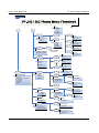
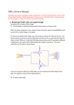
1
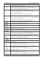
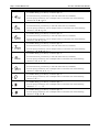
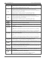
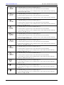
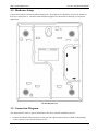
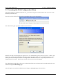
User Manual
VoIP Phone
VP-102/VP-202
DBL Technology Co.,Ltd.
Http://www.dbltek.com
[email protected]
[email protected]
Release 1.0
1
Http://www.dbltek.com
VP-102 / VP-202 User manual
Table of Contents
Overview ................................................................................................................................................................. 3
1.1 Key Features ................................................................................................................................................. 3
1.2 Shipping Contents ......................................................................................................................................... 4
1.3 Appearance.................................................................................................................................................... 5
1.4 VP-202 Keypad Layout ................................................................................................................................ 8
1.5 Hardware Setup........................................................................................................................................... 11
1.5 Connection Diagram ................................................................................................................................... 11
Web Configuration .............................................................................................................................................. 13
2.1 Starting Up .................................................................................................................................................. 13
2.2 Obtaining the VoIP Phone IP Address........................................................................................................ 13
2.3 Accessing the Web Configuration Menu .................................................................................................... 14
2.4 Configuring the VoIP Phone....................................................................................................................... 15
2.4.1 Preference ............................................................................................................................................ 16
2.4.2 Network Configuration ........................................................................................................................ 19
2.4.3 Call Settings......................................................................................................................................... 21
2.4.3.1 H.323 Phone ................................................................................................................................. 21
2.4.3.2 SIP Phone ..................................................................................................................................... 24
2.4.3.3 Media Settings .............................................................................................................................. 29
2.4.4 Phone Settings ..................................................................................................................................... 31
2.4.5 Phone Book.......................................................................................................................................... 33
2.4.5 Tools .................................................................................................................................................... 34
2.4.5 .1 Online Upgrade............................................................................................................................. 34
2.4.5 .2 Change Password.......................................................................................................................... 35
2.4.5 .3 Backup/Restore Configurations.................................................................................................... 35
2.4.5 .4 Reset Configuration ...................................................................................................................... 36
2.4.5 .5 Reboot........................................................................................................................................... 36
2.5 Gain Settings ................................................................................................................................................ 36
VoIP Phone Operation......................................................................................................................................... 38
3.1 Making a call............................................................................................................................................... 38
3.2 Making a Handsfree Call (Speakerphone / Headset) .................................................................................. 38
3.3 Answering an Incoming Call ...................................................................................................................... 39
3.4 Dialing from Phonebook ............................................................................................................................. 39
3.5 Viewing / Dialing from Call History........................................................................................................... 39
3.6 Redialing the Last Number (For VP-102 only)........................................................................................... 40
3.7 Putting a Call on Hold................................................................................................................................. 40
3.8 Transferring a Call ...................................................................................................................................... 40
3.9 Setting up a Call Conference....................................................................................................................... 40
3.10 Accessing Voice Messages ....................................................................................................................... 41
3.11 Answering a Call Waiting Call (For Model VP-202 only) ....................................................................... 41
3.12 Setting the the Ring Type.......................................................................................................................... 41
3.13 Adjusting the Ring Volume ...................................................................................................................... 41
3.14 Adjusting the Handset Receiver Volume .................................................................................................. 42
3.15 Adjusting the Speaker Volume .................................................................................................................. 42
3.16 Adjusting the LCD Contrast....................................................................................................................... 42
3.17 Resetting the Phone Configuration ............................................................................................................ 42
Appendix A Phone Menu................................................................................................................................. 43
2
Http://www.dbltek.com
VP-102 / VP-202 User Manual
1
Overview
The VP-100 Series VoIP Phone is designed as a low cost and high performance VoIP phones which
supports both H.323 and SIP standards. It offers lots of features and works seamlessly with most of the
existing VoIP systems. It is an ideal solution for both residential and business market to replace the
traditional analog and digital (pbx) phones.
1.1 Key Features
The major features of VP-102 / VP-202 VoIP Phones are:
•
•
•
•
•
•
•
•
•
•
•
Supports both H.323 V4.0 and SIP 2.0
Supports TCP/UDP/IP, RTP, HTTP, HTTPS, ARP, DNS, DHCP, NTP/SNTP, FTP, TFTP, and
SSL protocols
Supports H.225 V4, H.235 (MD5, HMAC-SHA1), H.245 Standards
Interoperable with various 3rd party VoIP end user devices, Proxy/Registrar/Server, and gateway
products
VP-102 supports single line
Vp-202 supports dual lines modes.
Supports popular vocoders including G.711 a-law and u-law, GSM, G.723.1, G.729a/b/ab
Supports standard voice features such as Caller ID Display or Block, Call Waiting, Call Hold,
Call Transfer, Call Forward, in-band and out-of-band DTMF (RFC2833/SIP INFO), and Dial
Plans
Supports conferencing, hands-free loudspeaker, phonebook, last number redial, call log, volume
control, and voicemail message indicator
Supports BASIC and DIGEST authentication (MD5, MD5-sess)
Provides easy configuration through automatic configuration, Web browser-based Graphical User
Interface (GUI), or, if desired, manual operation (phone keypad interface)
3
Http://www.dbltek.com
•
•
•
VP-102 / VP-202 User manual
Supports NTP and redundant DNS servers
NAT-friendly remote upgrade capability (via HTTP) even from behind firewall/NAT router.
Proprietary Firewall-Pass-Through Technology
1.2 Shipping Contents
Table 1 below shows the contents of the Phone package.
Item
4
Description
1
VP-102 / VP-202 Main body
2
Handset
3
Coiled cord
4
Ethernet Straight cable
5
Power Supply (optional) - 12VDC/500mA Output
External Power Supply. This is not required if your
network switch supports POE.
6
Phone warranty registration card
Http://www.dbltek.com
VP-102 / VP-202 User Manual
1.3 Appearance
The VP-102 keypad layout is shown and described below.
VP-102 Front View
– If Menu mode is not active, press this key to cancel the current operation and resumes to idle
LCD display.
1.
– If Menu mode is active, press this key to return to the last menu screen.
– While the phone is in menu mode. Press this key to confirm the selection or entry.
– While the phone is not in a call and a number is entered, press this key to dial the number.
2.
– While the phone is in idle, press this key to view the Dialed Call List while the LCD is in
idle screen.
3.
– Press this key to access the Menu mode.
4.
– Press this key to delete the last digit or alphabet entered (not active when the phone is in
menu selection mode).
5.
Up
– While the phone is in idle mode, press this key to view the Missed Call List.
5
Http://www.dbltek.com
VP-102 / VP-202 User manual
– While the phone is displaying phone entries or text, press this key to scroll the LCD screen
up one line till the top of the screen is reached.
– While the phone Is in idle mode, press this key to view the Answered Call List.
6.
Down
– While the phone is displaying phone entries or text, press this key to scroll the LCD screen
down one line till the bottom of the screen is reached.
– While the LCD is in idle display, press this key to increase the LCD contrast.
7.
Left
– While viewing Call Lists or Phone Book, press this key to scroll the LCD screen up one line
till the top of the screen is reached.
– While the phone is ringing, press this key to increase the ringer volume.
– While the phone is in use, press this key to increase the speaker volume.
– While the LCD is in idle display, press this key to decrease the LCD contrast.
8.
Right
– While viewing Call Lists or Phone Book, press this key to scroll the LCD screen down one
line till the top of the screen is reached.
– While the phone is ringing, press this key to decrease the ringer volume.
– While the phone is in use, press this key to decrease the speaker volume.
9.
10.
– Press this key to access the phone book while the phone is in idle.
– Press this key to access the voice mail server directly.
11.
– Press this key to activate the CONFERENCE mode while there is an active call and a call on
hold.
12.
– Press this key and dial a phone number to transfer the current call to this number. Both
attended and unattended modes are supported.
13.
– Press this key to answer a call waiting call or to switch between an active call and a call on
hold.
– While the phone is in use, press this key to mute the handset microphone.
14.
– While the phone is in idle mode, DND (DO NOT DISTURB) function is active. Press this
key to enable DND if DND is not active. Press this key to disable DND if DND is active.
– While the phone is in an active call, press this key to hold the call.
15.
16.
17.
– While there is a call on hold (LED flashes and Hold Warning tone is heard), press this key to
release the call on hold and resume as an active call.
– While the phone is in idle, press this key to access the Redial Call List.
– Depending on the phone setting, press this key to turn on either the Speakerphone or the
headset mode.
– For DTMF dialing, press this key to dial the digit “1”.
18.
– For menu selection, press this key to select the menu item 1 (if available).
– For text input, press this key to enter one of the following characters: [blank] 1.
– For DTMF dialing, press this key to dial the digit “2”.
– For menu selection, press this key to select the menu item 2 (if available).
19.
– For text input, press this key one or multiple times to enter either one of the following
characters: 2 A B C a b c.
– For DTMF dialing, press this key to dial the digit “3”.
20.
6
– For menu selection, press this key to select the menu item 3 (if available).
– For text input, press this key one or multiple times to enter either one of the following
Http://www.dbltek.com
VP-102 / VP-202 User Manual
characters: 3 D E F d e f.
– For DTMF dialing, press this key to dial the digit “4”.
– For menu selection, press this key to select the menu item 4 (if available).
21.
– For text input, press this key one or multiple times to enter either one of the following
characters: 4 G H I g h i.
– For DTMF dialing, press this key to dial the digit “5”.
– For menu selection, press this key to select the menu item 5 (if available).
22.
– For text input, press this key (one or multiple times) to enter either one of the following
characters: 5 J K L j k l.
– For DTMF dialing, press this key to dial the digit “6”.
– For menu selection, press this key to select the menu item 6 (if available).
23.
– For text input, press this key (one or multiple times) to enter either one of the following
characters: 5 J K L j k l.
– For DTMF dialing, press this key to dial the digit “6”.
– For menu selection, press this key to select the menu item 6 (if available).
24.
– For text input, press this key (one or multiple times) to enter either one of the following
characters: 7 P Q R S p q r s.
– For DTMF dialing, press this key to dial the digit “8”.
– For menu selection, press this key to select the menu item 8 (if available).
25.
– For text input, press this key one or multiple times to enter either one of the following
characters: 8 T U V t u v.
– For DTMF dialing, press this key to dial the digit “9”.
– For menu selection, press this key to select the menu item 9 (if available).
26.
– For text input, press this key one or multiple times to enter either one of the following
characters: 9 W X Y Z w x y z.
– For DTMF dialing, press this key to dial the digit “0”.
27.
– For text input, press this key one or multiple times to enter either one of the following
characters: 0 + -.
– For DTMF dialing, press this key to dial the digit “*”.
28.
– For text input, press this key one or multiple times to enter either one of the following
characters: * . : , ! ?.
– For DTMF dialing, press this key to dial the digit “#”.
29.
– For text input, press this key one or multiple times to enter either one of the following
characters: # @ % &.
7
Http://www.dbltek.com
VP-102 / VP-202 User manual
1.4 VP-202 Keypad Layout
The VP-202 keypad layout is shown and described below.
VP-202 Front View
– If Menu mode is not active, press this key to cancel the current operation and resumes to
idle LCD display.
1.
– If Menu mode is active, press this key to return to the last menu screen.
– While the phone is in menu mode. Press this key to confirm the selection or entry.
– While the phone is not in a call and a number is entered, press this key to dial the number.
2.
– While the phone is in idle, press this key to view the Dialed Call List while the LCD is in
idle screen.
– Press this key to access the Menu mode.
3.
– Press this key to delete the last digit or alphabet entered (not active when the phone is in
menu selection mode).
4.
– While the phone is in idle mode, press this key to view the Missed Call List.
5.
8
Up
– While the phone is displaying phone entries or text, press this key to scroll the LCD screen
Http://www.dbltek.com
VP-102 / VP-202 User Manual
up one line till the top of the screen is reached.
– While the phone Is in idle mode, press this key to view the Answered Call List.
6.
Down
– While the phone is displaying phone entries or text, press this key to scroll the LCD screen
down one line till the bottom of the screen is reached.
– While the LCD is in idle display, press this key to increase the LCD contrast.
7.
Left
– While viewing Call Lists or Phone Book, press this key to scroll the LCD screen up one
line till the top of the screen is reached.
– While the phone is ringing, press this key to increase the ringer volume.
– While the phone is in use, press this key to increase the speaker volume.
– While the LCD is in idle display, press this key to decrease the LCD contrast.
8.
Right
– While viewing Call Lists or Phone Book, press this key to scroll the LCD screen down
one line till the top of the screen is reached.
– While the phone is ringing, press this key to decrease the ringer volume.
– While the phone is in use, press this key to decrease the speaker volume.
9.
– Press this key to access the phone book while the phone is in idle.
10.
– Press this key to access the voice mail server directly.
11.
– Press this key to activate the CONFERENCE mode while there is an active call and a call
on hold.
12.
– This is a Line 1 selection key.
– If no number is entered (shown on LCD), press this key will select Line 1 for making a
call.
– If a number is entered (shown on LCD), press this key choose Line 1 to dial the number.
– This key can also be redefined if the phone is set to set to connect to only one server.
13.
– This is a Line 2 selection key.
– If no number is entered (shown on LCD), press this key will select Line 2 for making a
call.
– If a number is entered (shown on LCD), press this key choose Line 2 to dial the number.
– This key can also be redefined if the phone is set to set to connect to only one server.
14.
– While the phone is in use, press this key to mute the handset microphone.
– While the phone is in idle mode, DND (DO NOT DISTURB) function is active. Press this
key to enable DND if DND is not active. Press this key to disable DND if DND is active.
15.
– While the phone is in an active call, press this key to hold the call.
– While there is a call on hold (LED flashes and Hold Warning tone is heard), press this key
to release the call on hold and resume as an active call.
16.
– Press this key and dial a phone number to transfer the current call to this number. Both
attended and unattended modes are supported.
–
17.
– Depending on the phone setting, press this key to turn on either the Speakerphone or the
headset mode.
– For DTMF dialing, press this key to dial the digit “1”.
18.
– For menu selection, press this key to select the menu item 1 (if available).
– For text input, press this key to enter the characters: [blank] 1.
9
Http://www.dbltek.com
VP-102 / VP-202 User manual
– For DTMF dialing, press this key to dial the digit “2”.
19.
– For menu selection, press this key to select the menu item 2 (if available).
– For text input, press this key (one or multiple times) to enter either one of the following
characters: 2 A B C a b c.
– For DTMF dialing, press this key to dial the digit “3”.
20.
– For menu selection, press this key to select the menu item 3 (if available).
– For text input, press this key (one or multiple times) to enter either one of the following
characters: 3 D E F d e f.
21.
– For DTMF dialing, press this key to dial the digit “4”.
– For menu selection, press this key to select the menu item 4 (if available).
– For text input, press this key (one or multiple times) to enter either one of the following
characters: 4 G H I g h i.
– For DTMF dialing, press this key to dial the digit “5”.
22.
– For menu selection, press this key to select the menu item 5 (if available).
– For text input, press this key (one or multiple times) to enter either one of the following
characters: 5 J K L j k l.
– For DTMF dialing, press this key to dial the digit “6”.
23.
– For menu selection, press this key to select the menu item 6 (if available).
– For text input, press this key (one or multiple times) to enter either one of the following
characters: 6 M N O m n o.
– For DTMF dialing, press this key to dial the digit “6”.
24.
– For menu selection, press this key to select the menu item 6 (if available).
– For text input, press this key (one or multiple times) to enter either one of the following
characters: 7 P Q R S p q r s.
25.
– For DTMF dialing, press this key to dial the digit “8”.
– For menu selection, press this key to select the menu item 8 (if available).
– For text input, press this key one or multiple times to enter either one of the following
characters: 8 T U V t u v.
– For DTMF dialing, press this key to dial the digit “9”.
26.
– For menu selection, press this key to select the menu item 9 (if available).
– For text input, press this key one or multiple times to enter either one of the following
characters: 9 W X Y Z w x y z.
27.
28.
– For DTMF dialing, press this key to dial the digit “0”.
– For text input, press this key one or multiple times to enter either one of the following
characters: 0 + -.
– For DTMF dialing, press this key to dial the digit “*”.
– For text input, press this key one or multiple times to enter either one of the following
characters: * . : , ! ?.
– For DTMF dialing, press this key to dial the digit “#”.
29.
10
– For text input, press this key one or multiple times to enter either one of the following
characters: # @ % &.
Http://www.dbltek.com
VP-102 / VP-202 User Manual
1.5 Hardware Setup
Connect the handset cord to the handset and the base. The handset cord should be wired to the bottom of
the base as shown below. The base stand should be snapped on to the based for desktop or wall mount
application.
VP-102 Bottom View
1.5 Connection Diagram
The diagram below shows a typical installation of the device and the installation steps are:
1. Connect an Ethernet cable between the LAN port and a WAN network device (XDSL/Cable Modem,
router or gateway) for external network access.
11
Http://www.dbltek.com
VP-102 / VP-202 User manual
2. Optional: Connect an Ethernet cable between the PC port and a computer or network device. It is
intended to build a new local network segment (Fixed IP mode) or extend the existing network segment
(Bridge mode).
3. Optional: The MIC and EAR ports are intended headset operation. Connect a standard computer headset
to these ports.
4. Connect the AC/DC Adapter to the DC12V port and then the AC wall plug.
12
Http://www.dbltek.com
VP-102 / VP-202 User Manual
2
Web Configuration
2.1 Starting Up
Upon powering up for the first time, the VP-102 scans for available services for network connections. It will
then display the services available and prompt for user input.
1. DHCP service – This means that a local DHCP host is detected. Select this service to enable the phone to
obtain IP address and related information for the LAN port from the DHCP host.
2. PPPoE Dial Up – This service is intended for ADSL / Cable Modem user. Select this and the phone will
prompt for Username and Password for the PPPoE Dial Up.
3. Fixed IP – When the above two services are not available, this method can be used to access the network.
When this option is chosen, the phone will prompt for IP Address, Gateway Address, and Netmask. Please
contact your network administrator or ISP if you do not have the information required.
2.2 Obtaining the VoIP Phone IP Address
Once the LAN / PC port is setup properly, you are now ready to access the built-in web server for phone
configuration. To access the web server, you first need to retrieve the IP address using the following steps:
1. Press Menu (during on-hook or off-hook states)
2. Press 3 to select System Tools
3. Press 1 to select Phone Status
4. Press 1 to select LAN Port or 2 to select PC Port
5. Press 1 to select IP
The phone then displays LAN / PC port IP address:
xxx.xxx.xxx.xxx
where xxx is a number between 0 and 255.
13
Http://www.dbltek.com
VP-102 / VP-202 User Manual
2.3 Accessing the Web Configuration Menu
Once the IP Address is obtained in Section 2.2, you are now ready to access the built-in web server via a web
browser (IE, Firefox, etc.)
Enter the IP in the address field to login to the phone web server as shown below.
The web browser pops up a login window as shown below.
Both VP-102 and VP-202 support two login levels. For Administrator, please enter User name = “admin” and
Password = “admin” (factory default). For User, please enter User name = “user” and the Password = “1234”
(factory default). Both passwords can be changed in the Administrator mode. Only user password can be
changed in the User mode. Please keep a record of the new passwords if changed.
The Administrator mode allows full access to the built-in Web Server whereas the User mode restricts the user
from accessing the Call Settings page.
Once the login is successful, the Web Browser brings up the Status page as shown below.
14
Http://www.dbltek.com
VP-102 / VP-202 User Manual
2.4 Configuring the VoIP Phone
When entering the webpage, the default Status page is displayed as shown in Figure above.
The Status page provides a brief summary of the Phone and Network status.
Phone Information
¾ Serial Number
Each phone is assigned with a unique serial number by the factory. This number is important for auto
provision, technical support, and warranty repair.
¾ Firmware Version
This field identifies the current Firmware Version installed. Refer to this to determine if a firmware
upgrade is required.
¾ Hardware Model
This field identifies the hardware model and version.
¾ Phone Status
This field shows the status of server registration. The registration status is shown for each server / Line
registration. If the registration is successful, it displays “LOGIN”; otherwise, it displays “LOGOUT”.
Network Information
¾ LAN Port
This field shows IP address assigned to the LAN port.
¾ PC Port
15
Http://www.dbltek.com
VP-102 / VP-202 User Manual
This field shows IP address assigned to the PC port.
¾ PPPoE
This field shows the dial up status when PPPoE is enabled for ADSL login.
¾ Default Route
The Default Route shows the IP address of the default gateway / router that is used in the current network
environment.
¾ DNS Server
This field shows the IP address of the DNS server to be used for domain name interpretation.
There are six selections under the Configurations menu: Preference, Network, Call Settings, Phone Settings,
Save Changes, and Discard Changes.
To configure the phone, click on the appropriate selection (as discussed in Section 2.4.1 to 2.4.4) for the
changes desired.
Click on Save Changes to save all settings. A message window pops up to confirm when the save to flash
action is completed.
Click on Discard Changes to discards all changes. All settings are restored back to the values last saved.
2.4.1 Preference
Click on Preference to access this page for general settings configuration.
This page configures the general settings in the device: Language, Time Zone, Time server, Time Format,
Auto-Provision, Key(#) as Delimiter, Phone Book Mode, Network Tones, Speaker Phone Mic Input Gain,
Central Management.
a) Language - This field sets the language to be used for initial access to the built-in Web Server. The
languages currently available for selection are English and 简体中文(Simplified Chinese). Once the
16
Http://www.dbltek.com
VP-102 / VP-202 User Manual
language change is saved, it does not take effect until a new access to the web server.
To change the display language immediately, you can select the language icon as shown below. However,
this does not change the default language.
b) Time Zone – This parameter specifies your local time zone in order for the date/time to be correctly
displayed since the date/time obtained from a network time server is referenced to the Greenwich Mean
Time (GMT). If your time zone is 8 hours ahead of the GMT, you need to enter the value “GMT+8” in this
field.
c) Time Server – This parameter specifies the location of the network time server for obtaining the date and
time information. It accepts both domain name and IP address.
d) Time Format – This parameter specifies the time display format on the LCD.
e) Auto Provision – This parameter enables or disables the Auto Provision procedures. The Auto Provision
is a batch script to obtain configuration and firmware upgrade information from a server. Once this option
is enabled, two additional parameters (Provision Server and Provision Interval) are displayed. The
Provision Server specifies the location of the designated provision server. The auto provision procedure is
executed at boot up time and is repeated at a duration specified in the parameter Provision Interval.
f) Key(#) as Delimiter – When dialing a VoIP number, the VoIP device needs to wait for the user to complete
the number dialing before the call request is actually sent to the server. This parameter enables or disables
the “#” key to be used to signal the number dialing is completed and the call request can be execute
immediately.
g) Phone Book (for Model VP-202 only) – This parameter specifies if the phone should use one phone book
(Global mode) for both lines or an individual phone book for each line (By Line mode).
h) Network Tones – This parameter defines the network tones to be used. The predefined networks tones are:
China, Hong Kong, Taiwan, New Zealand, United Kingdom, United States, Korea, Slovenia,
Czechoslovakia, India, Singapore, Israel, Malaysia, Indonesia, Thailand, Romania, Bangladesh, and
Customized. The Customized option allows user to define his own network tones. If the desired network
tones selection is not available, user can use this Customized option.
17
Http://www.dbltek.com
VP-102 / VP-202 User Manual
Each network tone is defined as
nc, rpt, c1on, c1off, c2on, c2off, c3on, c3off, f1, f2, f3, f4, p1, p2, p3, p4
where
nc is the number of cadences
rpt is the repeat counter(0 - infinite, 1~n - repeat 1~n times)
c1on is the cadence one on duration (in milliseconds)
c1off is cadence one off duration (in milliseconds)
c2on is the cadence two on duration (in milliseconds)
c2off is the cadence two off duration (in milliseconds)
c3on is the cadence three on duration (in milliseconds)
c3off is the cadence three off duration (in milliseconds)
f1 is the tone #1, 300-3000(Hz)
f2 is the tone #2, 300-3000(Hz)
f3 is the tone #3, 300-3000(Hz)
f4 is the tone 34, 300-3000(Hz)
p1 is the attenuation index for tone #1, 0~31(0=3dB, -1dB increments)
p2 is the attenuation index for tone #2, 0~31(0=3dB, -1dB increments)
p3 is the attenuation index for tone #3, 0~31(0=3dB, -1dB increments)
p4 is the attenuation index for tone #4, 0~31(0=3dB, -1dB increments)
Two network tone definition samples are shown below.
1. A New Zealand Dial Tone (400 Hz) is defined as 0,0,0,0,0,0,0,0,400,0,0,0,10,0,0,0.
2. A New Zealand Busy tone (400Hz with a cadence of 500ms on and 500ms off (repeat)) is defined as
1,0,500,500,0,0,0,0,400,0,0,0,10,0,0,0.
i)
18
Speakerphone Mic Input Gain – This speakerphone Microphone gain can be tuned to optimize its
acoustic performance via this field. Four gain settings are available: 8, 12, 16, 20 dB.
Http://www.dbltek.com
j)
VP-102 / VP-202 User Manual
Centralized Management – This is a proprietary protocol defined to communicate with phone via a PC
program. Please contact your supplier for more information on this feature. This parameter enables this
feature.
2.4.2 Network Configuration
This page configures the network interface for LAN Port and PC Port.
LAN Port – The LAN port is intended for internet access. It is normally connected to a network device (router
or ADSL modem) which has internet access. The following 3 modes are available for selection.
1. DHCP – This mode should be selected If the network device functions as a DHCP host, This allows the
HT-812P to obtain all related network information / settings from the DHCP host.
2. Static IP – This mode sets the LAN port IP manually which can either be a public or private IP. Other
network settings (Subnet Mask, Default Route, Primary DNS, Secondary DNS) should also be entered
accordingly.
19
Http://www.dbltek.com
VP-102 / VP-202 User Manual
3. PPPoE – This selection is intended for broadband connection (ADSL / Cable modem) that requires dial up /
authentication using PPPoE protocol. Both User Name and Password are required. Please consult your
service provider for more information if needed. One advantage with the PPPoE dial up is that the IP
address obtained for the LAN port is normally a public IP.
More advanced parameters for 802.1q VLAN and MAC settings are available. Please consult your network
administrator for assistance if needed.
PC PORT – The PC port is intended to provide an Ethernet connection to other network devices (for example:
PC, network HUB.). Two modes of operation are available:
1.
2.
Bridge mode - This mode allows the network traffics at the PC port to be bypassed to LAN port. This
means that the network device share the same network segment as the LAN port. There is no IP address
assigned to the PC port.
Fixed IP - This mode sets the PC port IP Addresss (private IP) and Subnet Mask manually. This creates
a new network segment for the network devices connected to the PC Port.
To simplify network IP assignments, enable the DHCP Server for the PC Port. This allows network
devices connected Port to obtain network IP and related information from the PC Port. Please consult your
network administrator for proper settings of the DHCP Server
20
Http://www.dbltek.com
VP-102 / VP-202 User Manual
2.4.3 Call Settings
This page configures all related settings for VoIP Service. Based on the two protocols (H.323 and SIP)
supported, the operation of HT-812P is divided as two Endpoint Types: H.323 Phone and SIP Phone. Some
of the parameters are unique to the Endpoint Type and are described separately below.
REMARK:
Model VP-102 supports only one SIP registration (1 Line).
Model VP-202 supports two SIP registrations (2 Lines).
2.4.3.1 H.323 Phone
The H.323 Phone selection for Endpoint Type refers to the protocol used.
The basic H.323 settings are:
1.
Phone Number - This parameter assigns the phone number used for registration in Gatekeeper Mode.
This is used as an alias in Direct Mode.
2.
Display Name – This parameter (optional) specifies the Caller name and is transmitted as part of the caller
ID.
3.
H.323 ID - This parameter is specified in the H.323 protocol. It is an identifier containing an alphanumeric
21
Http://www.dbltek.com
VP-102 / VP-202 User Manual
string. Some gatekeepers may use this ID for authentication.
4.
Endpoint Mode – Gatekeeper Mode supports making a VoIP call via a call server. Registration to the
server is required. Direct Mode supports making a VoIP call by dialing the IP addresses or an alias.
5.
Gatekeeper Address - This assigns the location of the Gatekeeper for VoIP Service.
6.
Authentication – If H.235 authentication is required, enable this field and enter the H.235 ID and
Password.
7.
Call Forward – This features allows a call to be forwarded to as specified in the fields shown below.
a) Always Forward – Entering a number in this field always forwards all calls to the number entered. No
Reply Forward and Busy Forward are ignored.
b) No Answer Forward – Entering a number in this field enable this functions. Calls are forwarded to the
number entered if there is no answer.
c) Busy Forward - Entering a number in this field enable this functions. Calls are forwarded to the number
entered if the phone / line is busy.
8.
Ring Type – This parameter specifies the ring type to be used for the corresponding line..
Advanced Settings
More settings are available under the Advanced Settings tab. These setting s are common to all H.323
configurations. Depending on your network requirements, please consult your network administrator for the
correct configuration.
22
Http://www.dbltek.com
1.
2.
3.
4.
5.
6.
VP-102 / VP-202 User Manual
RAS Port – This Port is used to convey the registration, admissions, bandwidth change, and status
messages between two H.323 endpoints. If not specified, the port address is assigned automatically.
Q.931 Port – This port is used for call signaling to convey Call Setup and teardown messages between two
H.323 endpoints. If not specified, the port address is assigned automatically.
H.245 Port – The H.245 requires at least 2 ports for media control protocol. It should be specified as a port
range. If not specified, the port address is assigned automatically.
Fast Start - Fast Start is a new method of call setup that bypasses some usual steps in order to make it
faster. In addition to the speed improvement, Fast Start allows the media channels to be operational before
the CONNECT message is sent, which is a requirement for certain billing procedures. Leave this enabled
if you are not sure.
Register Mode - Two registration modes are support. Register Multiple Numbers mode means that
multiple numbers are registered in a single registration message. Register Multiple Time mode means that
each number is registered in a separate registration message.
DTMF Signaling – This parameter sets the method of sending DTMF signals. Inband measns that the
DTMF signal is sent as an analog signal via the voice channel. Outband means that the DTMF signal is
sent as DTMF command via the data channel and is commonly known as RFC2833. In Outband mode, a
DTMF payload type is required and the default type is set to 101.
23
Http://www.dbltek.com
VP-102 / VP-202 User Manual
7.
Signaling QoS – This parameter sets the QoS mode for VoIP Signaling for better response time and more
reliable VoIP Call signaling. Both IP TOS and Diffserv modes are supported. Please check with your
network administrator or ISP for the correct setting.
8.
Signaling NAT Traversal – NAT Traversal is an algorithm designed to solve a common problem in
TCP/IP networking in establishing connections between hosts in private TCP/IP networks that use NAT
devices. This parameter only sets the NAT Traversal mode for VoIP signaling. The 3 methods supported
are NAT Citron, Port-forward/DMZ, and Relay Proxy.
Both NAT Citron and Port-forward/DMZ are well known NAT protocols are are widely used; however,
they require the support of local network.
Relay Proxy mode is a proprietary NAT protocol and it is designed for NAT Traversal with the capability
of avoiding VoIP blockings. All VoIP signaling and/or media packets are encapsulated (encrypted as well
if enabled) and transmitted via another port/channel to our proprietary Relay Server. Please contact your
service provider to determine if this mode is supported.
2.4.3.2 SIP Phone
The SIP Phone selection for Endpoint Type refers to the protocol used.
Model VP-102 supports only one line registration.
Model VP-202 supports up to two line registrations to the same or different SIP Servers.
The Call Settings pages for both models are shown below. Some of the parameters in VP-202 are discussed in
the Phone Setting Page.
VP-102
24
VP-202
Http://www.dbltek.com
VP-102 / VP-202 User Manual
The basic SIP settings are:
1.
Phone Number – This parameter assigns the phone number used for SIP registration.
2.
Display Name – This parameter (optional) specifies the Caller name and is transmitted as part of the caller
ID.
3.
SIP Proxy – A SIP Proxy acts as a call manager of all incoming and outgoing calls. Specify the location
(IP address / domain name) of the designated SIP Proxy used for SIP service. The standard port used is
5060. To specify a non-standard signaling port, add “:<port number>” to the of the location. For example:
If SIP Proxy = yousippbx.com, the signaling port is the standard port 5060. If SIP Proxy =
yoursippbx.com:15060, the signaling port is 15060.
4.
SIP Registrar – A SIP Registrar maintains a database of all SIP phones registered and their contact
information. Specify the location (IP address / domain name) of the designated SIP Registrar. The
standard port used is 5060. To specify a non-standard signaling port, add “:<port number>” to the of the
25
Http://www.dbltek.com
VP-102 / VP-202 User Manual
location. For example: If SIP Proxy = yousippbx.com, the signaling port is the standard port 5060. If SIP
Proxy = yoursippbx.com:15060, the signaling port is 15060.
5.
Registry Expiry(s) – This specifies the expiry duration at the SIP Registrar after a successful registration.
The range is 60 to 36400 seconds.
6.
Outbound Proxy – A network node acts as proxy for outbound traffic between a client and a server.
Please contact your network administration to determine if this proxy is available or not.
7.
Home Domain – This field enables the use of home domain name is SIP registration instead of IP address.
8.
Authentication ID – This field specifies the ID to be used for Authentication during a SIP registration.
9.
Password –This field specifies the password used for Authentication during a SIP registration.
10. Backup Server (For Model VP-102 only) – The backup option provides settings for a SIP backup server.
Once the designated SIP Proxy and/ SIP Registrar fail, the backups will be used automatically. Once the
primary servers are up, the phone will switch back automatically.
11. Call Waiting (For Model VP-202 only) – This parameter enables or disables the Call Waiting feature.
12. Call Forward Type – This defines the Call Forward condition and the available options are:
a)
b)
c)
d)
e)
Not Forward – Call forward is disabled.
Unconditional Forward – Call is always forwarded.
Busy Forward – Call is forwarded when the line is in use / engaged.
No Answer Forward – Call is forwarded when it is not answered.
Busy or No Answer Forward – Call is forwarded when the line is in use or not answered.
13. Forward Number – This defines the number to be used for Call Forward.
14. Voice-mail Number – This defines the access code for the voice mail server when the
key is pressed.
15. Hotline (VP-202) – Hotline is a feature to dial out the preset number automatically whenever the phone
goes off hook. This feature for the corresponding line is enabled when a number is entered. The Line 1
Hotline Number (if set) is dialed out since it is the default line to be used when the phone is off hook. To
dial the Line 2 Hotline Number, press the L2 key directly.
16. Dial Plan (VP-202) – Please see item # 5 of Section 2.4.4.
17. Ring Type (VP-202) – This specifies the ring type for the corresponding line.
18. Auto Answer Mode (VP-202) – This enables the auto answer mode (for the corresponding line) for all
calls or for a list of the calls specified.
26
Http://www.dbltek.com
VP-102 / VP-202 User Manual
Advanced Settings
More settings are available under the Advanced Settings tab. Depending on your network requirements, please
consult your network administrator for the correct configuration.
1.
Signaling Port – This Port is used to convey signaling message with the SIP Proxy. The standard port
number is 5060.
2.
NAT Keep-alive – When enabled, a dummy packet I sent to the local firewall / router in order to keep the
ports opened for VoIP service.
3.
P2P – This enables Peer-to-Peer calls.
4.
Virtual Ringback – This enables a ringback tone to be generated whenever a call is made.
5.
DTMF Signaling – This parameter sets the method of sending DTMF signals. Inband means that the
DTMF signal is sent as an analog signal via the voice channel. Outband means that the DTMF signal is
sent as DTMF command via the data channel. Both RFC2833 and SIP INFO methods are supported. For
RFC2833, a DTMF payload type is required and the default type is set to 101.
27
Http://www.dbltek.com
VP-102 / VP-202 User Manual
6.
Signaling QoS – This parameter sets the QoS mode for VoIP Signaling for better response time and more
reliable VoIP Call signaling. Both IP TOS and Diffserv modes are supported. Please check with your
network administrator or ISP for the correct setting.
7.
Signaling Encryption – Three types of encryption are supported and they can be enabled individually.
These are non-standard encryption for signaling. Please make sure that your SIP Service Provider can
support the encryption(s) enabled.
a)
b)
c)
d)
e)
8.
RC4 – RC4 Encryption Key is required when it is enabled.
Fast –
VOS – This encryption is developed by a network equipment vendor in Nanjing, China.
AVS – This encryption is developed by a network equipment vendor in Shanghai, China.
ET263 – This encryption is supported by major network equipment vendors in China.
Signaling NAT Traversal – NAT Traversal is an algorithm designed to solve a common problem in
TCP/IP networking in establishing connections between hosts in private TCP/IP networks that use NAT
devices. This parameter only sets the NAT Traversal mode for VoIP signaling. The 2 methods supported
are STUN(RFC3489) and Relay Proxy. A STUN Server is required for STUN(RFC3489).
Relay Proxy mode is a proprietary NAT protocol and it requires the use of our Relay Proxy Server. All
VoIP signaling packets are encapsulated (encrypted as well if enabled) and transmitted via another
port/channel. Three relay modes of operation are supported.
28
Http://www.dbltek.com
VP-102 / VP-202 User Manual
Mode 1: Use UDP packets and encryption.
Mode 2: Use UDP packets and encryption; use single UDP port.
Mode 3: Use TCP packets and encryption; Use single TCP port;
The mode 2 and mode 3 are the passive and the port use is assigned by the RELAY SERVER.
Note: For Service providers, RELAY Proxy software is available at no charge. Please contact your
supplier for support. For end user, please contact your service provider to see if this feature is available.
2.4.3.3 Media Settings
Once a VoIP call is established, the Media channel is used for voice transmission. The settings listed below
configure the performance and operation of the Media channel.
1.
RTP Port (range) – Audio stream is transmitted via Real Time Protocol (RTP) and at least 4 ports are used
per voice channel. The default port range is 16384 – 32768. Specify the port range depending on your
network environment if needed.
2.
Packet length (ms) – This specify the length of a voice packet. The default packet length is 20 ms.
3.
Jitter Buffer Mode –Three jitter modes are available. The Fixed Mode, which is the default mode, is a
simple first in first out mode, with a fixed jitter buffer delay. By definition the jitter buffer depth is twice
the jitter buffer delay. The Sequential Mode is also a fixed jitter buffer delay mode, but in this mode the
jitter buffer function looks at the packet timestamp for dropped or out of sequence packet problems. The
data packets are sorted based on the packet timestamp. The Adaptive Mode optimizes the size of the jitter
buffer delay and depth in response to network conditions, in addition to the sequential mode.
4.
Media QoS – QoS is also available for Media packets to improve voice quality. This is rather significant
in a network environment with large amount of data traffics. Both IP TOS and DiffServ methods are
supported.
29
Http://www.dbltek.com
VP-102 / VP-202 User Manual
5.
Encryption – For secure voice transmission, RC4 and ET263 Encryptions are supported. Please make sure
your service provider can support this encryption method before enabling this feature.
6.
Symmetric RTP – Enable the media channel to use symmetric RTP ports. Some network environment
demand the use of Symmetric RTP.
7.
Media NAT Traversal – NAT Traversal can be set independently for Media packets. This gives a more
flexible setting for various network environment. Three modes are supported: STUN(RFC 3489), Portforward/DMZ, and Relay Proxy.
Relay Proxy mode is a proprietary NAT protocol and it requires the use of our Relay Proxy Server. All
VoIP signaling packets are encapsulated (encrypted as well if enabled) and transmitted via another
port/channel. Three relay modes of operation are supported.
Mode 1: Use UDP packets and encryption.
Mode 2: Use UDP packets and encryption; use single UDP port.
Mode 3: Use TCP packets and encryption; Use single TCP port;
The mode 2 and mode 3 are the passive and the port use is assigned by the RELAY SERVER.
Note: For Service providers, RELAY Proxy software is available at no charge. Please contact your
supplier for support. For end user, please contact your service provider to see if this feature is available.
8.
30
Audio Codec Preference – The table below list the voice codec priorities in descending order. Each voice
codec can be enabled (place a check mark in the check box) or disabled individually. Select the voice code
and then click on the UP or DOWN button to move the order on the list.
Http://www.dbltek.com
VP-102 / VP-202 User Manual
2.4.4 Phone Settings
The Phone Settings page configures the FXS port and its related operations. They are described in details
below.
1. Title on LCD – The text entered here is shown on the LCD as a default message when the phone is
idle.
2. Auto Dial – This field enables a number entered to be dialed out automatically once the Auto-Dial
Timeout expires.
3. Auto-dial Timeout – The field specifies the timeout duration (in second) for automatically dialing out
the number entered.
4. Hotline (VP-102)– This feature enables the phone to dial out the Hotline Number entered
automatically whenever the phone goes off hook.
5. Dial Plan (Digit Map) – Dial Plan defines how a number (VoIP) is processed when the device
receives it. This field is located in the Calling Setting Window and it is available for both H.323 Phone
and SIP Phone. The Dial Plan is very flexible and can be configured for a wide range of dialing
applications.
The basic syntax is “<event>:<action>|<event>:<action>|…”, where
<event> defines the event to be matched. A event consists of a sequence of digits. If a specific digit
has a limited range, use the syntax [A-B] where A and B are both digit (0 to 9) and B is
greater than A. The length of the input number can be limited by using “X” to represent each
unknown digit. If this field is omitted, it means any event.
<action> defines the action to be taken on the number received and it consists of “–“ (minus), “+”
(plus), and digits. “-“ followed by digits means to remove the digits from the beginning of
the number entered. “+” followed by digits means to add the digits in front of the number
entered.
“|”
means or and the order of priority is from left to right.
31
Http://www.dbltek.com
VP-102 / VP-202 User Manual
Note: For practical use, it should not be possible to reach the maximum length of the Dial Plan string.
Examples:
a) Dial Plan = “010:-010” means that the number dialed out will have the first 3 digits ”010” removed
when a number with the first digits as “010” is entered.
a) Number entered = “01082121234”, actual number dialed = “82121234”.
b) Number entered = “82121234”, actual number dialed = “82121234”.
b) Dial Plan = “1:+00” means that the number dialed out will have the “00” added in front of the
number entered when a number with the first digit as “1” is entered,.
a) Number entered = “1082121234”, actual number dialed = “00182121234”.
b) Number entered = “82121234”, actual number dialed = “82121234”.
c) Dial Plan = “001:-001+1751” means that the number dialed out will the first 3 digits “001” changed
to “1751” when a number with the first digits as “001” is entered.
a) Number entered = “00182121234”, actual number dialed = “175282121234”.
b) Number entered = “82121234”, actual number dialed = “82121234”.
d) Dial Plan = “XXXX:” means that the input number is limited to 4-digit long and will be dialed out
immediately when the fourth digit is entered.
e) Dial Plan = “13XXXXXXXXX:+0” means that the input number is restricted to 11-digit long and
the first two digits must be “13”. When this condition is matched, the number dialed out will have
a leading “0” added.
a) Number entered = “13901234567”, actual number dialed = “013901234567”.
b) Number entered = “12801234567”, actual number dialed = “12801234567”.
f) Dial Plan = “13[6-9]XXXXXXXX:+0” means that the input number is restricted to 11-digit long and
the first two digits must be “13” and the third digit can be 6, 7, 8,or 9. When this condition is
matched, the number dialed out will have a leading “0” added.
a) Number entered = “13901234567”, actual number dialed = “013971234567”.
b) Number entered = “13001234567”, actual number dialed = “13001234567”.
Please note that the above samples are simple and intended to show the meaning of various rules. They
may not have any practical meaning. A combination of these rules (joined with the symbol “|”) can be
realized for a much more complicated dialing application.
6.
Menu Configuration Password – This field specifies if a login ID / password is required to access
the Device CFG submenu in the Phone Menu.
7.
Missed Call LED Indication – This field enables the LED to flash when a miss call occurs.
8.
Keypad Lock – This parameter disable the keypad.
9.
Default Handsfree Device – This parameter specifies to use the Speakerphone or Headset when the
he voice path (Speakerphone or Headset) When this feature is enabled, the Hot Line Number defined
will be dialed out automatically whenever the phone is off hook.
10. Auto Answer Mode – This parameter enables and defines the conditions of Auto Answer Mode.
Select All for answering all incoming calls automatically.
32
Http://www.dbltek.com
VP-102 / VP-202 User Manual
Select By List for answering only the number listed on the Auto Answer List (total 10 entries).
2.4.5 Phone Book
This page lists all the phone book entries for editing. Just click on New Contact to add a new contact as shown
in the window below.
Enter the Name (optional) and Number fields and then click
shown below.
to add this entry to the phone book as
33
Http://www.dbltek.com
VP-102 / VP-202 User Manual
Repeat the above to add more contacts. Click on Edit to edit or Del to delete the corresponding entry.
2.4.5 Tools
The Tools section is intended to offer the following functions: Online Upgrade, Change Password,
Backup/Restore Configurations, Reset Config, and Reboot as shown below.
2.4.5 .1 Online Upgrade
Click on the Online Upgrade tab to perform manual firmware upgrade. Enter the upgrade address as shown
below. Please contact your service provider to determine if there is a new firmware available.
34
Http://www.dbltek.com
VP-102 / VP-202 User Manual
WARNING: Once the upgrade starts, a message window is displayed to show the upgrade status. DO
NOT TURN OFF THE POWER WHILE THE FIRMWARE UPGRADE IS IN PROCESS!
2.4.5 .2 Change Password
HT-812P supports two login levels to the built-in webpage. The User level is intended for general user and is
restricted from accessing the Call Settings page and Reset Configuration function. In this level, only the
password for the user level can be changed. The default password for the user level (login ID = user) is “1234”.
The Administrator level allows full accessing to the HT-812P configurations. In this level, the password for
both levels can be change. The default password for the administrator level (login ID = admin) is “admin”.
It is important to record the new password(s). If the admin password is lost, a special star command is available
to reset all system settings. Please refer to section 3.1.1 for more information.
2.4.5 .3 Backup/Restore Configurations
This function backups or restores the phone configuration.
button to save the current configuration as config.dat which is placed on the desktop. The
Click on the
Password field is optional. If a password is entered, the file config.dat is encrypted and password protected.
To restore a configuration file, click on Browse button to locate the file and enter the password, if required.
Then click on
to restore the phone configuration.
35
Http://www.dbltek.com
VP-102 / VP-202 User Manual
2.4.5 .4 Reset Configuration
This function can only be accessed in administrator login level. Click on the Reset Configuration tab to
initiate the reset process. A message windows pops up to ask for confirmation. Click “Yes” to reset all
configurations back factory defaults. Click “No” to cancel. Once the reset process is completed, the device
reboots itself.
2.4.5 .5 Reboot
Click on the Reboot tab to reboot the device. This will take couple minutes.
2.5 Gain Settings
This Gain Settings page is hidden and is only intended for advanced user who is technically capable. The block
diagram below shows the various gain stages in the phone.
36
Http://www.dbltek.com
VP-102 / VP-202 User Manual
The blocks highlighted in green are available for programming in the URL below.
http://xxx.xxx.xxx.xxx//en_US/gain.html
The first 3 rows in the gain settings page shows the 3 modes of operation: Handset, Handsfree, and Headset.
Each mode uses the same configuration as shown in the block diagram above. The left hand column (first 3
rows) shows the mode of operation. The various gain settings are described as follows:
g) Microphone AFE refers to the Analog Front End Gain block (G1).
h) Microphone VGC refers to the Volume Gain (G3). This gain should be changed with caution since it
affects the tone level as well. If the tone generated is a DTMF tone, changing this gain may affect the
detection of the DTMF tone by the outside network.
i)
Speaker refers to the Volume Gain (G4).
j)
Microphone CGC on the 4th row in the Gain Settings page refers to the Encoder Calibration Gain CGC
(G2). Changing this gain does not affect the signals from the Tone / FSK generator.
k) Speaker Levels refer to the relative levels in the volume settings. There are a total of 6 volume settings
from 1 to 6. The relative levels are listed in ascending order. When the volume setting is set to 1, the
Decoder Calibration Gain CGC (G5) is set to its preset value (cannot be changed) + the relative level
specified for volume setting 1. If the relative level is blank, G5 is set to its minimum value. This
means that the speaker is effectively muted.
l)
The Analog Front End Gain (G6) is factory preset and cannot be changed.
37
Http://www.dbltek.com
VP-102 / VP-202 User Manual
3
VoIP Phone Operation
3.1 Making a call
1.
2.
3.
Pick up handset.
Dial a phone number.
Press OK (or # key if enabled) or wait for Auto Dial timeout (programmable in the Preference
page).
For VP-202, the default line is Line 1. If Line 2 is preferred, press L2 instead of OK to make the
call.
3.2 Making a Handsfree Call (Speakerphone / Headset)
1.
2.
3.
Press
(optional).
Dial a phone number.
Press OK (or # key if enabled)or wait for Auto Dial timeout.
For VP-202, the default line is Line 1. If Line 2 is preferred, press L2 instead of OK to make the
call.
Depending on the Default Handsfree Device setting, the call will be routed to the specified
device (Speakerphone or headset).
Note: L1/R1 and L2/R2 keys can be redefined as R1 and R2 for other functions. When they are redefined as other functions, they will be referred as R1 and R2 The default functions for L1/R1 and
L2/R2 keys are for Line 1(L1) selection and Line 2 (L2) selection respectively.
38
Http://www.dbltek.com
VP-102 / VP-202 User Manual
3.3 Answering an Incoming Call
Answering a call can be done manually or automatically.
1.
Manual Answer Mode
to answer the call. For handsfree
When the phone rings, just pick up the handset or press
mode, the call will be routed to speakerphone or headset depending on the Default Handsfree Device
setting.
2.
Auto Answer Mode
When the Auto Answer Mode in the Phone Settings Page is set to All or By List, the phone will
answer an incoming call as defined below.
-
All means that all incoming calls will be answered automatically.
-
By List means only the incoming call number matches the Auto Answer List will be answered
automatically.
Please refer to Section 2.4.4 for more information.
3.4 Dialing from Phonebook
1
Press
(or
to access Phone Book directly, skip 2)
2
Select PHONE BOOK (Menu Item 2). For VP-202 and By Line Phone Book moede, choose
PHONE BOOK L1 for Line 1 and PHONE BOOK L2 for line 2.
3
Select VIEW.
4
Press Up or Down to search for a Phone Book Entry.
5
Press OK to select the highlighted entry.
6
Select DIAL to dial out the phone number.
3.5 Viewing / Dialing from Call History
1
While the Phone is on hook or idle, press Up to view the Missed Call List, Down to view the
Answered Call List, or OK to view Dialed Call List.
2
For VP-202, Choose MISSED L1 / Answered L1 / Dialed L1 for line 1 and MISSED L2 /
Answered L2 / Dialed L2 for line 2.
3
Press Up or Down to scroll the list.
4
Press OK to select the phone number.
5
Select DIAL to dial the phone number immediately.
39
Http://www.dbltek.com
VP-102 / VP-202 User Manual
3.6 Redialing the Last Number (For VP-102 only)
1
Press
.
2
Pick up the handset /
to dial the number.
1
Pick up the handset /
.
2
Press
3
Press OK to dial the number.
Or
.
3.7 Putting a Call on Hold
1
Press
while a call is in progress to hold the call.
2
LCD shows “HOLDING” / Hold LED flashes.
3
A HOLD alerting tone is generated regularly if the handset is placed on the cradle.
4
Pick up the handset / press
5
Press
hears a dial tone for making another call.
again to release the call on Hold.
3.8 Transferring a Call
1
Party A and B are in an active call.
2
Party A presses
3
Party A hears a dial tone and make a call to party C.
key to initiate the call transfer.
4 Unattended Transfer: Party A hangs up for unattended transfer. Party B is now waiting for Party C to
answer the call.
or
5
Attended Transfer: Party A waits for Party C to answer the call. Once Party C answers the call, Party
A hangs up to complete the transfer.
If Party C does not answer the call, party A can press Hold to resume the call
with Party B.
3.9 Setting up a Call Conference
40
1
Party A and B are in an active call.
2
VP-102: Party A presses
to put party B on Hold and get a dial to make another call.
Http://www.dbltek.com
VP-102 / VP-202 User Manual
VP-202: Party A presses L1 (if the current call in using Line 1)/ L2 (if the current call is using Line 2)
to put party B on Hold and get a dial to make another call.
3
Party A makes a call to party C.
4
Party C answers the call.
5
Party A presses
to start a conference with both party B and C.
3.10 Accessing Voice Messages
1
Press
to access your voice mail server. The Voice Mail Number must be set in the Call Settings
Page in order for this key to function.
2
For VP-202, choose the desired Voice Mail Server (L1 / L2).
3
The phone then connects to the voice mail server for further operation.
3.11 Answering a Call Waiting Call (For Model VP-202 only)
When you are talking on the phone and another call comes in on your phone extension, a short tone sounds
in your handset and the LCD displays an incoming call message.
This feature must be enabled in the Call Settings Page for each line.
To answer a Call Waiting Call:
1. View the incoming call information on the LCD
2. Press the corresponding line key (L1 / L2) to put the current call on hold and answer the Call Waiting
Call.
3. Press the line key again to switch between the two calls.
3.12 Setting the the Ring Type
1. Press
.
2. Select SYSTEM TOOLS.
3. Select Ring Type.
4. Select Type 1 to 4 as desired.
5. Press
to exit to the last menu level.
3.13 Adjusting the Ring Volume
1. Press
.
2. Select SYSTEM TOOLS.
41
Http://www.dbltek.com
VP-102 / VP-202 User Manual
3. Select Ring Volume.
4. Press Up or Down to increase or decrease the ring volume. Actual ringing is generated to show the ring
level set and the LCD also shows the current ring level setting.
5. Press
to exit to the last menu level.
Alternative: Ring volume level can also be adjusted while the phone is ringing. Just press Up or Down key
to adjust the volume level.
3.14 Adjusting the Handset Receiver Volume
1.
Pick up the handset
2.
Press Up or Down to increase or decrease the handset receiver volume as shown on the LCD.
3.15 Adjusting the Speaker Volume
1.
Press the Speaker button.
2.
Press Up or Down to increase or decrease the speaker volume as shown on the LCD.
3.16 Adjusting the LCD Contrast
1.
While the phone is idle, press Up or Down to increase or decrease the LCD Contrast level as
shown on the LCD.
3.17 Resetting the Phone Configuration
T0 reset the SIP Phone to factory configuration:
1.
Press Menu
2.
Select SYSTEM TOOLS
3.
Select RESET CONFIG
4.
Press OK
5.
Enter the Username (default is admin) and Password (default is dbl#admin)
This will reset the entire phone configuration back to factory default settings.
42
Http://www.dbltek.com
VP-102 / VP-202 User Manual
Appendix A Phone Menu
43
Http://www.dbltek.com
VP-102 / VP-202 User Manual
6/19/2008
Page 2/2
LINE 1
1. TYPE 1
2. TYPE 2
3. TYPE 3
4. TYPE 4
3
1
1
TYPE 1
RING TYPE
4
AUTOCFG
1. ENABLE (if disabled)
1. DISABLE (if enabled)
SET TYPE 1
2
1. LINE 1
2. LINE 2
2
LINE 2
1
1. TYPE 1
2. TYPE 2
3. TYPE 3
4. TYPE 4
SET TYPE 2
3
SPEED DIAL
1. KEY 1
2. KEY 2
.
0. KEY 10
1
4
TYPE 4
SET TYPE 4
DEVICE CFG
Login: user
Password: 1234 (if enabled)
1. LAN PORT
2. PC PORT
3. GATEWAY
4. DNS
1
KEY 1:
KEY 2
2
KEY 2:
KEY 10
0
4
KEY 10:
AUTO
1
1. + AUTO
LAN PORT
1. + AUTO
2. FIXED IP
3. PPPOE
2
1
IP ADDRESS
FIXED IP
IP ADDRESS:
1. IP ADDRESS
2. SUBNET MASK
2
3
2
1
1
FIXED IP
1. + FIXED IP
2. BRIDGE
1. IP ADDRESS
2. SUBNET MASK
GATEWAY
4
1
PRIMARY DNS
IP ADDRESS:
2
SUBNET MASK
MASK:
2. + BRIDGE
1. PRIMARY DNS
2. SECONDARY DNS
SECONDARY DNS
IP ADDRESS:
44
2
BRIDGE
DNS
IP ADDRESS
IP ADDRESS:
2
GATEWAY:
SUBNET MASK
MASK:
PC PORT
3
TYPE 3
SET TYPE 3
Enable / Disable
AUTOCFG
KEY 1
5
TYPE 2