1
General-Purpose AC Servo
J2-Super Series
Equivalatent to CC-Link
MODEL
MR-J2S- CP-S084
MR-J2S-T01
Specifications
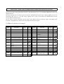
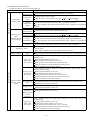
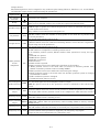
ADDITION TO MR-J2S-CP-S084 SERVO AMPLIFIER SPECIFICATIONS
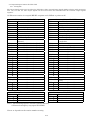
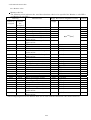
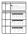
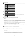
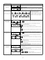
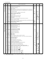
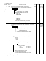
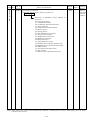
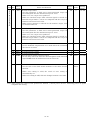
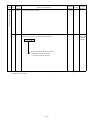
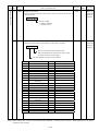
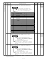
The device number and signal abbreviation of each I/O signal of the servo amplifier MR-J2S-CP-S084 are
indicated below.
The input signals can be used as either CC-Link or CN1A/CN1B external input signals. Make selection in
parameters No. 116, 117, 118. The output signals can be used as CC-Link and CN1A/CN1B external
output signals simultaneously.
In the factory setting, Forward rotation stroke end (RYn4), Reverse rotation stroke end (RYn5) and
Proximity dog (RYn3) are valid as CN1A/CN1B external input signals.
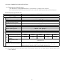
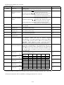
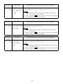
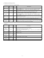
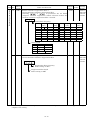
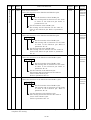
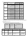
(1) When one station is occupied
PLC Servo Amplifier (RYn)
(Note)
Device No.
Signal name
Servo Amplifier
External
input
abbreviation
Signal
(Note)
Device No.
PLC (RXn)
Signal name
abbreviation
External
input
CN1B18
Signal
RYn0
Servo-on
SON
CN1B15
RXn0
Ready
RD
RYn1
Forward rotation start
ST1
CN1B8
RXn1
In position
INP
RYn2
Reverse rotation start
ST2
CN1B9
RXn2
Rough match
CPO
RYn3
Proximity dog
DOG
RXn3
Home position return
completion
ZP
RYn4
Forward rotation stroke end
LSP
RXn4
Limiting torque
TLC
RXn6
Electromagnetic brake
interlock
MBR
CN1A8
CN1B16
CN1B17
RYn5
Reverse rotation stroke end
LSN
RYn6
Automatic/manual selection
MD0
RXn7
Temporary stop
PUS
RYn7
Temporary stop
STP
RXn8
Monitoring
MOF
RYn8
Monitor output execution
demand
MOR
RXn9
Instruction code execution
completion
COF
RYn9
Instruction code execution
demand
COR
RXnA
Warning
WNG
CN1B7
RYnA
Point table No. selection (bit0)
DI0
CN1B5
RXnB
Battery warning
BWND
RYnB
Point table No. selection (bit1)
DI1
CN1B14
RXnC
Movement finish
MEND
RYnC
Point table No. selection (bit2)
DI2
RXnE
Position range output
WNG
RYnD
Point table No. selection (bit3)
DI3
RX(n+1)A
Trouble
ALM
RYnE
Point table No. selection (bit4)
DI4
RX(n+1)B
Remote bureau
communication ready
CRD
RY1A
Reset
RES
Note. "n" is determined by station number setting.
CN1B4
CN1A18
CN1B6
CN1B18
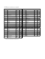
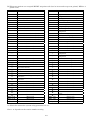
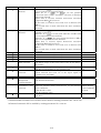
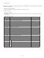
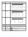
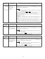
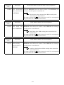
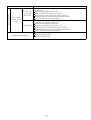
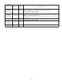
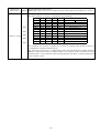
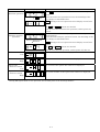
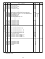
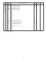
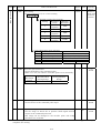
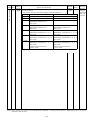
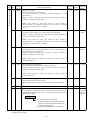
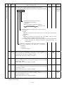
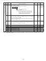
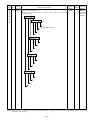
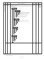
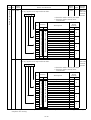
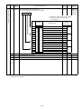
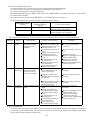
(2) When two stations are occupied
PLC Servo Amplifier (RYn)
(Note)
Device No.
Signal name
Servo Amplifier PLC (RXn)
External
Signal
input
abbreviation
(Note)
Device No.
Signal name
External
input
abbreviation
Signal
RYn0
Servo-on
SON
CN1B15
RXn0
Ready
RD
RYn1
Forward rotation start
ST1
CN1B8
RXn1
In position
INP
RYn2
Reverse rotation start
ST2
CN1B9
RXn2
Rough match
CPO
RXn3
Home position return
completion
ZP
RXn4
Limiting torque
TLC
RXn6
Electromagnetic brake
interlock
MBR
RYn3
Proximity dog
DOG
RYn4
Forward rotation stroke end
LSP
CN1A8
CN1B16
CN1B17
RYn5
Reverse rotation stroke end
LSN
RYn6
Automatic/manual selection
MD0
RXn7
Temporary stop
PUS
RYn7
Temporary stop
STP
RXn8
Monitoring
MOF
RYn8
Monitor output execution
demand
MOR
RXn9
Instruction code execution
completion
COF
RYn9
Instruction code execution
demand
COR
RXnA
Warning
WNG
CN1B7
RYnA
Point table No. selection (bit0)
DI0
CN1B5
RXnB
Battery warning
BWND
RYnB
Point table No. selection (bit1)
DI1
CN1B14
RXnC
Movement finish
MEND
RYnC
Point table No. selection (bit2)
DI2
RXnE
Position range output
WNG
RYnD
Point table No. selection (bit3)
DI3
RX(n+2)0
Position instruction completion
RYnE
Point table No. selection (bit4)
DI4
RX(n+2)1
Speed instruction completion
RY(n+2)0
Position instruction demand
(Note2)
RX(n+2)2
Point table No. selection (bit0)
PT0
RY(n+2)1
Speed instruction demand
(Note2)
RX(n+2)3
Point table No. selection (bit1)
PT1
RY(n+2)6
External torque limit selection
TL2
RX(n+2)4
Point table No. selection (bit2)
PT2
RY(n+2)7
Proportion control
PC
RX(n+2)5
Point table No. selection (bit3)
PT3
RY(n+2)8
Gain switch
CDP
RX(n+2)6
Point table No. selection (bit4)
PT4
RY(n+2)A
Position/speed designation
system selection
RX(n+3)A
Trouble
ALM
RY(n+2)B
Absolute value/incremental
value selection
Note 1. "n" is determined by station number setting.
2. Select the command system in parameter No. 41.
CN1B18
CN1B4
CN1A18
CN1B6
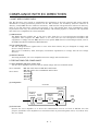
Safety Instructions
(Always read these instructions before using the equipment.)
Do not attempt to install, operate, maintain or inspect the servo amplifier and servo motor until you have read
through this Instruction Manual, Installation guide, Servo motor Instruction Manual and appended documents
carefully and can use the equipment correctly. Do not use the servo amplifier and servo motor until you have a
full knowledge of the equipment, safety information and instructions.
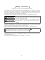
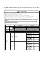
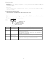
In this Instruction Manual, the safety instruction levels are classified into "WARNING" and "CAUTION".
WARNING
Indicates that incorrect handling may cause hazardous conditions,
resulting in death or severe injury.
CAUTION
Indicates that incorrect handling may cause hazardous conditions,
resulting in medium or slight injury to personnel or may cause physical
damage.
Note that the CAUTION level may lead to a serious consequence according to conditions. Please follow the
instructions of both levels because they are important to personnel safety.
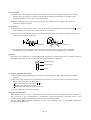
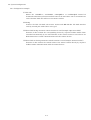
What must not be done and what must be done are indicated by the following diagrammatic symbols:
: Indicates what must not be done. For example, "No Fire" is indicated by
: Indicates what must be done. For example, grounding is indicated by
.
.
In this Instruction Manual, instructions at a lower level than the above, instructions for other functions, and so
on are classified into "POINT".
After reading this Instruction Manual, always keep it accessible to the operator.
A- 1
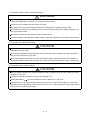
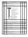
1. To prevent electric shock, note the following:
WARNING
Before wiring or inspection, switch power off and wait for more than 10 minutes. Then, confirm the voltage
is safe with voltage tester. Otherwise, you may get an electric shock.
Connect the servo amplifier and servo motor to ground.
Any person who is involved in wiring and inspection should be fully competent to do the work.
Do not attempt to wire the servo amplifier and servo motor until they have been installed. Otherwise, you
may get an electric shock.
Operate the switches with dry hand to prevent an electric shock.
The cables should not be damaged, stressed, loaded, or pinched. Otherwise, you may get an electric shock.
2. To prevent fire, note the following:
CAUTION
Do not install the servo amplifier, servo motor and regenerative brake resistor on or near combustibles.
Otherwise a fire may cause.
When the servo amplifier has become faulty, switch off the main servo amplifier power side. Continuous
flow of a large current may cause a fire.
When a regenerative brake resistor is used, use an alarm signal to switch main power off. Otherwise, a
regenerative brake transistor fault or the like may overheat the regenerative brake resistor, causing a fire.
3. To prevent injury, note the follow
CAUTION
Only the voltage specified in the Instruction Manual should be applied to each terminal. Otherwise, a burst,
damage, etc. may occur.
Connect the terminals correctly to prevent a burst, damage, etc.
Ensure that polarity ( ,
) is correct. Otherwise, a burst, damage, etc. may occur.
During power-on or for some time after power-off, do not touch or close a parts (cable etc.) to the servo
amplifier heat sink, regenerative brake resistor, servo motor, etc. Their temperatures may be high and you
may get burnt or a parts may dameged.
A- 2
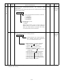
4. Additional instructions
The following instructions should also be fully noted. Incorrect handling may cause a fault, injury, electric
shock, etc.
(1) Transportation and installation
CAUTION
Transport the products correctly according to their weights.
Stacking in excess of the specified number of products is not allowed.
Do not carry the motor by the cables, shaft or encoder.
Do not hold the front cover to transport the controller. The controller may drop.
Install the servo amplifier in a load-bearing place in accordance with the Instruction Manual.
Do not climb or stand on servo equipment. Do not put heavy objects on equipment.
The controller and servo motor must be installed in the specified direction.
Leave specified clearances between the servo amplifier and control enclosure walls or other equipment.
Do not install or operate the servo amplifier and servo motor which has been damaged or has any parts
missing.
Provide adequate protection to prevent screws and other conductive matter, oil and other combustible
matter from entering the servo amplifier.
Do not drop or strike servo amplifier or servo motor. Isolate from all impact loads.
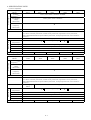
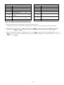
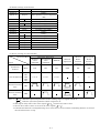
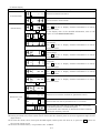
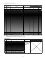
When you keep or use it, please fulfill the following environmental conditions.
Conditions
Servo amplifier
Servo motor
[ ] 0 to 55 (non-freezing)
0 to 40 (non-freezing)
Operation
[ ] 32 to 131 (non-freezing)
32 to 104 (non-freezing)
Ambient
temperature
[ ]
20 to 65 (non-freezing)
15 to 70 (non-freezing)
Storage
[ ]
4 to 149 (non-freezing)
5 to 158 (non-freezing)
Operation
90%RH or less (non-condensing)
80%RH or less (non-condensing)
Ambient
humidity
Storage
90%RH or less (non-condensing)
Ambience
Indoors (no direct sunlight) Free from corrosive gas, flammable gas, oil mist, dust and dirt
Altitude
Max. 1000m (3280 ft) above sea level
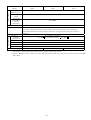
HC-KFS Series
HC-MFS Series
X Y : 49
HC-UFS13 to 73
HC-SFS81
HC-SFS52 to 152
HC-SFS53 to 153
X Y : 24.5
HC-RFS Series
[m/s2]
5.9 or less
HC-UFS 72 152
HC-SFS121 201
HC-SFS202 352
X : 24.5
HC-SFS203 353
Y : 49
HC-UFS202 to 502
HC-SFS301
X : 24.5
HC-SFS502 to 702
Y : 29.4
(Note)
Vibration
HC-KFS Series
HC-MFS Series
X Y : 161
HC-UFS 13 to 73
HC-SFS81
HC-SFS52 to 152
HC-SFS53 to 153
X Y : 80
HC-RFS Series
19.4 or less
[ft/s2]
HC-UFS 72 152
HC-SFS121 201
HC-SFS202 352
X : 80
HC-SFS203 353
Y : 161
HC-UFS202 to 502
HC-SFS301
X : 80
HC-SFS502 to 702
Y : 96
Note. Except the servo motor with reduction gear.
Environment
A- 3
CAUTION
Securely attach the servo motor to the machine. If attach insecurely, the servo motor may come off during
operation.
The servo motor with reduction gear must be installed in the specified direction to prevent oil leakage.
For safety of personnel, always cover rotating and moving parts.
Never hit the servo motor or shaft, especially when coupling the servo motor to the machine. The encoder
may become faulty.
Do not subject the servo motor shaft to more than the permissible load. Otherwise, the shaft may break.
When the equipment has been stored for an extended period of time, consult Mitsubishi.
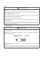
(2) Wiring
CAUTION
Wire the equipment correctly and securely. Otherwise, the servo motor may misoperate.
Do not install a power capacitor, surge absorber or radio noise filter (FR-BIF option) between the servo
motor and servo amplifier.
Connect the output terminals (U, V, W) correctly. Otherwise, the servo motor will operate improperly.
Do not connect AC power directly to the servo motor. Otherwise, a fault may occur.
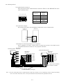
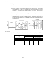
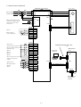
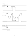
The surge absorbing diode installed on the DC output signal relay must be wired in the specified direction.
Otherwise, the forced stop (EMG) and other protective circuits may not operate.
Servo
Amplifier
Servo
Amplifier
COM
(24VDC)
COM
(24VDC)
Control
output
signal
Control
output
signal
RA
RA
(3) Test run adjustment
CAUTION
Before operation, check the parameter settings. Improper settings may cause some machines to perform
unexpected operation.
The parameter settings must not be changed excessively. Operation will be insatiable.
A- 4
(4) Usage
CAUTION
Provide a forced stop circuit to ensure that operation can be stopped and power switched off immediately.
Any person who is involved in disassembly and repair should be fully competent to do the work.
Before resetting an alarm, make sure that the run signal is off to prevent an accident. A sudden restart is
made if an alarm is reset with the run signal on.
Do not modify the equipment.
Use a noise filter, etc. to minimize the influence of electromagnetic interference, which may be caused by
electronic equipment used near the servo amplifier.
Use the servo amplifier with the specified servo motor.
The electromagnetic brake on the servo motor is designed to hold the motor shaft and should not be used
for ordinary braking.
For such reasons as service life and mechanical structure (e.g. where a ballscrew and the servo motor
are coupled via a timing belt), the electromagnetic brake may not hold the motor shaft. To ensure safety,
install a stopper on the machine side.
(5) Corrective actions
CAUTION
When it is assumed that a hazardous condition may take place at the occur due to a power failure or a
product fault, use a servo motor with electromagnetic brake or an external brake mechanism for the
purpose of prevention.
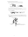
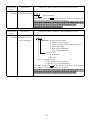
Configure the electromagnetic brake circuit so that it is activated not only by the interface unit signals but
also by a forced stop (EMG).
Contacts must be open when
servo-off, when a trouble (ALM)
and when an electromagnetic brake
interlock (MBR).
Circuit must be
opened during
forced stop (EMG).
Servo motor
RA EM1
24VDC
Electromagnetic brake
When any alarm has occurred, eliminate its cause, ensure safety, and deactivate the alarm before
restarting operation.
When power is restored after an instantaneous power failure, keep away from the machine because the
machine may be restarted suddenly (design the machine so that it is secured against hazard if restarted).
A- 5
(6) Maintenance, inspection and parts replacement
CAUTION
With age, the electrolytic capacitor will deteriorate. To prevent a secondary accident due to a fault, it is
recommended to replace the electrolytic capacitor every 10 years when used in general environment.
Please consult our sales representative.
(7) General instruction
To illustrate details, the equipment in the diagrams of this Instruction Manual may have been drawn
without covers and safety guards. When the equipment is operated, the covers and safety guards must
be installed as specified. Operation must be performed in accordance with this Instruction Manual.
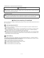
About processing of waste
When you discard servo amplifier, a battery (primary battery), and other option articles, please follow the law of
each country (area).
FOR MAXIMUM SAFETY
This product is not designed or manufactured to be used in equipment or systems in situations that can
affect or endanger human life.
When considering this product for operation in special applications such as machinery or systems used in
passenger transportation, medical, aerospace, atomic power, electric power, or submarine repeating
applications, please contact your nearest Mitsubishi sales representative.
Although this product was manufactured under conditions of strict quality control, you are strongly advised
to install safety devices to forestall serious accidents when it is used in facilities where a breakdown in the
product is likely to cause a serious accident.
EEP-ROM life
The number of write times to the EEP-ROM, which stores parameter settings, etc., is limited to 100,000. If
the total number of the following operations exceeds 100,000, the servo amplifier and/or converter unit may
fail when the EEP-ROM reaches the end of its useful life.
Write to the EEP-ROM due to parameter setting changes
Home position setting in the absolute position detection system
Write to the EEP-ROM due to device changes
Write to the EEP-ROM due to point table changes
A- 6
COMPLIANCE WITH EC DIRECTIVES
1. WHAT ARE EC DIRECTIVES?
The EC directives were issued to standardize the regulations of the EU countries and ensure smooth
distribution of safety-guaranteed products. In the EU countries, the machinery directive (effective in
January, 1995), EMC directive (effective in January, 1996) and low voltage directive (effective in January,
1997) of the EC directives require that products to be sold should meet their fundamental safety
requirements and carry the CE marks (CE marking). CE marking applies to machines and equipment
into which servo amplifiers have been installed.
(1) EMC directive
The EMC directive applies not to the servo units alone but to servo-incorporated machines and
equipment. This requires the EMC filters to be used with the servo-incorporated machines and
equipment to comply with the EMC directive. For specific EMC directive conforming methods, refer to
the EMC Installation Guidelines (IB(NA)67310).
(2) Low voltage directive
The low voltage directive applies also to servo units alone. Hence, they are designed to comply with
the low voltage directive.
This servo is certified by TUV, third-party assessment organization, to comply with the low voltage
directive.
(3) Machine directive
Not being machines, the servo amplifiers need not comply with this directive.
2. PRECAUTIONS FOR COMPLIANCE
(1) Servo amplifiers and servo motors used
Use the servo amplifiers and servo motors which comply with the standard model.
Servo amplifier
Servo motor
:MR-J2S-10CP-S084 to MR-J2S-700CP-S084
MR-J2S-10CP1-S084 to MR-J2S-40CP1-S084
:HC-KFS
HC-MFS
HC-SFS
HC-RFS
HC-UFS
(2) Configuration
Control box
Reinforced
insulating type
Reinforced
insulating
transformer
No-fuse
breaker
Magnetic
contactor
NFB
MC
24VDC
power
supply
Servo
amplifier
Servo
motor
SM
(3) Environment
Operate the servo amplifier at or above the contamination level 2 set forth in IEC664. For this
purpose, install the servo amplifier in a control box which is protected against water, oil, carbon, dust,
dirt, etc. (IP54).
A- 7
(4) Power supply
(a) Operate the servo amplifier to meet the requirements of the overvoltage category II set forth in
IEC664. For this purpose, a reinforced insulating transformer conforming to the IEC or EN
standard should be used in the power input section.
(b) When supplying interface power from external, use a 24VDC power supply which has been
insulation-reinforced in I/O.
(5) Grounding
(a) To prevent an electric shock, always connect the protective earth (PE) terminals (marked
servo amplifier to the protective earth (PE) of the control box.
) of the
(b) Do not connect two ground cables to the same protective earth (PE) terminal. Always connect the
cables to the terminals one-to-one.
PE terminals
PE terminals
(c) If a leakage current breaker is used to prevent an electric shock, the protective earth (PE)
terminals of the servo amplifier must be connected to the corresponding earth terminals.
(6) Wiring
The cables to be connected to the terminal block of the servo amplifier must have crimping terminals
provided with insulating tubes to prevent contact with adjacent terminals.
Crimping terminal
Insulating tube
Cable
(7) Auxiliary equipment and options
(a) The no-fuse breaker and magnetic contactor used should be the EN or IEC standard-compliant
products.
(b) The sizes of the cables meet the following requirements. To meet the other requirements, follow
Table 5 and Appendix C in EN60204-1.
Ambient temperature: 40 (104) [ ( )]
Sheath: PVC (polyvinyl chloride)
Installed on wall surface or open table tray
(c) Use the EMC filter for noise reduction.
(8) Performing EMC tests
When EMC tests are run on a machine/device into which the servo amplifier has been installed, it
must conform to the electromagnetic compatibility (immunity/emission) standards after it has
satisfied the operating environment/electrical equipment specifications.
For the other EMC directive guidelines on the servo amplifier, refer to the EMC Installation
Guidelines(IB(NA)67310).
A- 8
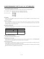
CONFORMANCE WITH UL/C-UL STANDARD
(1) Servo amplifiers and servo motors used
Use the servo amplifiers and servo motors which comply with the standard model.
Servo amplifier series :MR-J2S-10CP-S084 to MR-J2S-700CP-S084
MR-J2S-10CP1-S084 to MR-J2S-40CP1-S084
Servo motor series
:HC-KFS
HC-MFS
HC-SFS
HC-RFS
HC-UFS
(2) Installation
Install a fan of 100CFM air flow 10.16 cm (4 in) above the servo amplifier or provide cooling of at least
equivalent capability.
(3) Short circuit rating
This servo amplifier conforms to the circuit whose peak current is limited to 5000A or less. Having
been subjected to the short-circuit tests of the UL in the alternating-current circuit, the servo
amplifier conforms to the above circuit.
(4) Capacitor discharge time
The capacitor discharge time is as listed below. To ensure safety, do not touch the charging section for
10 minutes after power-off.
Servo amplifier
MR-J2S-10CP(1)-S084 20CP(1)-S084
MR-J2S-40CP(1)-S084 60CP-S084
MR-J2S-70CP-S084 to 350CP-S084
MR-J2S-500CP-S084
to
MR-J2S-700CP-S084
Discharge time [min]
1
2
3
5
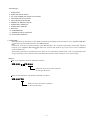
(5) Options and auxiliary equipment
Use UL/C-UL standard-compliant products.
(6) Attachment of a servo motor
For the flange size of the machine side where the servo motor is installed, refer to “CONFORMANCE
WITH UL/C-UL STANDARD” in the Servo Motor Instruction Manual.
(7) About wiring protection
For installation in United States, branch circuit protection must be provided, in accordance with the
National Electrical Code and any applicable local codes.
For installation in Canada, branch circuit protection must be provided, in accordance with the Canada
Electrical Code and any applicable provincial codes.
A- 9
MEMO
A - 10
- CONTENTS 1. OVERVIEW
2. SPECIFICATION LISTS
3. CC-Link COMMUNICATION FUNCTION
4. POSITIONING FUNCTION
5. CONNECTION DIAGRAM
6. TERMINAL EXPLANATION
7. OPERATION TIMINGS
8. OPERATION MODES
9. DISPLAY
10. PARAMETERS
11. PROTECTIVE FUNCTIONS
12. OUTLINE DRAWING
1. OVERVIEW
This specification describes the CC-Link equivalent positioning function built-in servo amplifier MR-J2SCP-S084 and CC-Link interface unit MR-J2S-T01.
Connected with the CC-Link interface unit MR-J2S-T01, the CC-Link equivalent positioning function
built-in servo amplifier MR-J2SCP-S084 can control and monitor up to 42 axes of servo amplifiers
from the PLC side.
Positioning operation is performed on the basis of the positioning information, such as positioning data
(target positions), motor speeds and acceleration/deceleration time constants, set to point tables.
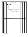
<Model>
The servo amplifier model is defined as follows.
MR-J2S-
CP-S084
CP-S084
Indicates that the model conforms
to this specification.
The CC-Link interface unit model is defined as follows.
MR-J2S-T01
MR-J2S-T01
Indicates that the model conforms
to this specification.
1-1
(1) Features of the communication function
1) Fast communication
Cyclic transmission of not only bit data but also word data can be made to enable fast communication.
(a) 10Mbps high-speed communication can be achieved
(b) The adoption of the broadcast polling system ensures high speed of max. 3.9ms to 6.7ms link scan.
2) Communication speed/distance variable system
Selection of the speed and distance enables use in a wide range from a system that demands high speed
to a system that requires a long distance.
3) Prevention of system fault (station separation function)
The bus connection system does not affect communications with normal remote and local stations if any
remote or local station becomes faulty at power-off, etc.
The two-piece terminal block allows the unit to be changed during a data link.
4) Compatibility with Factory Automation
Factory Automation can be easily applied to servo amplifiers by sharing a link system as remote device
stations of CC-Link and controlling and monitoring them with the user program of the PLC.
Various settings of motor speeds, acceleration/deceleration times, etc. can be changed and confirmed
from the PLC.
(2) Features of the servo section
In addition to the basic performance of the MR-J2S, etc., the servo section has the following positioning function.
1) Positioning using up to 31 point tables.
2) Position data can be specified directly from outside (only when two stations are occupied)
3) Speed data can be specified directly from outside (only when two stations are occupied)
4) Absolute position system compatibility
5) Eight different home position return methods
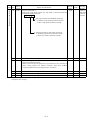
(3) System configuration
Operations using the MR-J2S-CP-S084 will be described.
Using CC-Link, a system can be configured freely from a single-axis system to an up to 42-axis system.
Further, external input signals can be assigned to the CN connector pins by setting parameters Pr. 116, 117 and 118.
Data for operation consists of the following point table.
Point table
Item
Setting Range
Unit
0.001mm
0.01mm
0.1mm
1mm
r/min
Position data
999999
to
999999
Motor speed
0 to maximum speed
Acceleration time constant
0 to 20000
msec
Deceleration time constant
0 to 20000
msec
Dwell time
0 to 20000
msec
Auxiliary function
0 to 3
The following number of points can be set to the point table.
Number of Points
Designation using CC-Link input
Designation using CN1 signals
Point Table
external input signals
When 1 station When 2 stations
is occupied
are occupied
Point table
31(1 to 31)
31(1 to 31)
31(1 to 31)
1-2
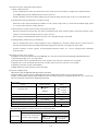
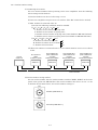
1) Operation using CC-Link communication function
All signals can be controlled by CC-Link communication. In addition, point tables can be set, point tables
can be selected, parameter values can be changed, set and monitored, and servo motors can be run.
RS-232C
MR-J2SCP-S084 MR-J2S-T01
No. 2
axis
No. 1
axis
Personal
computer
MR-J2SMR-J2SMR-J2SMR-J2S-T01
MR-J2S-T01
CP-S084
CP-S084 MR-J2S-T01 CP-S084
1
1
No. 3
axis
Max. No.
42 axis
For control
PLC CC-Link
master unit
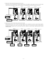
2) Operation by CN1 external input signals and CC-Link
Using parameters No. 116, 117 and 118, input signals can be assigned to the CN1 external input signals.
The signals assigned to the CN1 external input signals cannot be used with the CC-Link communication
function. Output signals can be used with the CN1 connector and CC-Link communication function
simultaneously.
RS-232C
MR-J2SCP-S084 MR-J2S-T01
No. 1
axis
Personal
computer
MR-J2SMR-J2SMR-J2SMR-J2S-T01
MR-J2S-T01
CP-S084
CP-S084 MR-J2S-T01 CP-S084
No. 2
axis
No. 3
axis
Max. No.
42 axis
For control
PLC CC-Link
master unit
External
I/O signals
External
I/O signals
External
I/O signals
1-3
External
I/O signals
MEMO
1-4
2. SPECIFICATION LISTS
(1) Servo amplifiers
Power supply
Servo Amplifier
Model
MR-J2S-10CP
-S084
MR-J2S-20CP
-S084
MR-J2S-40CP
-S084
MR-J2S-60CP
-S084
Voltage,
frequency Note 1
Three-phase 200V to 230VAC, 50/60Hz
Permissible
voltage
fluctuation
Three-phase 170V to 253VAC
Permissible
frequency
fluctuation
Within 5%
Control method
MR-J2S-70CP
-S084
Sine-wave PWM control/current control method
Protective functions Overcurrent shutoff, regenerative overvoltage shutoff, overload shutoff (electronic thermal relay),
servo motor overheat protection, encoder error protection, regenerative error protection,
undervoltage/instantaneous power failure protection, overspeed protection, error excessive
protection
Power supply
Environment
Structure
Self-cooling, open (IP00)
Ambient
temperature
0 to 55
(non-freezing), storage:
20 to 65
Humidity
90%RH or less (non-condensing), storage: 90%RH or less
Ambience
Inside control box, without corrosive gas, flammable gas, oil mist, dust and dirt
Altitude
Maximum 1000m above sea level
Vibration
5.9m/s2 or less
Weight (kg)
0.7
Servo Amplifier
Model
MR-J2S-100CP
-S084
0.7
1.1
MR-J2S-200CP
-S084
MR-J2S-350CP
-S084
1.1
1.7
MR-J2S-500CP
-S084
MR-J2S-700CP
-S084
Voltage,
frequency Note 1
Three-phase 200V to 230VAC, 50/60Hz
Permissible
voltage
fluctuation
Three-phase 170V to 253VAC
Permissible
frequency
fluctuation
Within 5%
Control method
Sine-wave PWM control/current control method
Protective functions Overcurrent shutoff, regenerative overvoltage shutoff, overload shutoff (electronic thermal relay),
servo motor overheat protection, encoder error protection, regenerative error protection,
undervoltage/instantaneous power failure protection, overspeed protection, error excessive
protection
Environment
Structure
Self-cooling, open
(IP00)
Ambient
temperature
Forced cooling, open (IP00)
0 to 55
(non-freezing), storage:
20 to 65
Humidity
90%RH or less (non-condensing), storage: 90%RH or less
Ambience
Inside control box, without corrosive gas, flammable gas, oil mist, dust and dirt
Altitude
Maximum 1000m above sea level
Vibration
5.9m/s2 or less
Weight (kg)
1.7
2.0
2.0
2-1
4.9
7.2
Power supply
Servo Amplifier
Model
MR-J2S-10CP1
-S084
MR-J2S-20CP1
-S084
MR-J2S-40CP1
-S084
Voltage,
frequency Note 1
Three-phase 100V to 120VAC, 50/60Hz
Permissible
voltage
fluctuation
Three-phase 85V to 127VAC
Permissible
frequency
fluctuation
Within 5%
Control method
Sine-wave PWM control/current control method
Protective functions Overcurrent shutoff, regenerative overvoltage shutoff, overload shutoff (electronic thermal relay),
servo motor overheat protection, encoder error protection, regenerative error protection,
undervoltage/instantaneous power failure protection, overspeed protection, error excessive
protection
Environment
Structure
Ambient
temperature
Self-cooling, open (IP00)
0 to 55
(non-freezing), storage:
20 to 65
Humidity
90%RH or less (non-condensing), storage: 90%RH or less
Ambience
Inside control box, without corrosive gas, flammable gas, oil mist, dust and dirt
Altitude
Maximum 1000m above sea level
Vibration
5.9m/s2 or less
Weight (kg)
0.7
0.7
1.1
Note: 1. The servo motor output values and rated speeds assume the power supply voltage and frequency indicated in the
tables. They cannot be guaranteed when a power supply voltage drop occurs.
2. For the compatible motors, refer to the Servo Motor Instruction Manual as they are the same as those of the MRJ2S-A Servo.
2-2
3. CC-Link COMMUNICATION FUNCTION
3.1 Communication Specifications
The MR-J2S-CP-S084 MR-J2S-T01 is equivalent to a remote device station.
For details of the PLC side specifications, refer to the CC-Link System Master Unit Manual.
Communication specification list
MR-J2S-T01
5VDC Supplied from servo amplifier.
Ver.1.10
MR-J2S- CP -S084
10M / 5M / 2.5M / 625K / 156Kbps
Broadcast polling system
Frame synchronization system
NRZI
Bus format (EIA RS485 compliant)
Power supply
Applicable CC-Link version
Applicable servo amplifier
Communication speed
Communication system
Synchronization system
Encoding system
Transmission path format
Error control system
Connection cable
Transmission format
Remote station number
(Note)
Cable length
CC-Link
Unit Model
CRC(X16
X12 X5
1)
Shielded three-core twisted pair cable
HDLC compliant
1 to 64
Communication speed
156Kbps
625Kbps
2.5Mbps
5Mbps
10Mbps
Maximum overall cable
length
1200m
900m
400m
160m
100m
Interstation cable
length
Number of connected units
0.2m or more
Up to 42 units (when 1 station is occupied by one unit), (up to 32 units
when two stations are occupied by one unit) when there are only
remote device stations. Can be used with other devices.
Note: Change depending on the used cables. For details, refer to the CC-Link System Master/Local Unit
User's Manual.
3-1
3.2 System Configuration
3.2.1 Configuration example
(1) PLC side
Mount the "AJ61BT11", "A1SJ61BT", "AJ61QBT11" or "A1SJ61QBT" Control &
Communication Link system master/local unit on the main base unit or extension base
unit of the PLC CPU that will act as the master station.
(2) Wiring
Connect the PLC CC-Link unit master station and MR-J2S-T01 CC-Link interface
units by twisted pair cables (three-wire type).
(3) When CPU having automatic refresh function is used (example: QnA series CPU)
Transfer of data to/from the corresponding devices by sequence ladders makes them
refreshed automatically by the refresh buffer of the master station at execution of an
END instruction to make communications with the remote devices.
(4) When CPU not having automatic refresh function is used (example: AnA series CPU)
Transfer of data to/from the refresh buffer of the master station directly by sequence
ladders makes communications with the remote devices.
3-2
3.2.2 Wiring method
(1) Communication connector
The pin layout of the communication connector CN10 on the MR-J2S-T01 slave
unit is shown below.
Pin No.
1 2
3
4
5
1
2
3
4
5
Signal
Name
DA
DB
DG
SLD
FG
(2) Connection example
The wiring of the option unit and PLC CC-Link master unit is shown below.
PLC CC-Link
master unit
MR-J2S-T01
DA
DB
DG
SLD
DA
DB
DG
SLD
FG
(3) Example of connecting multiple servo amplifiers
Servo amplifiers can share a link system as remote I/O stations of CC-Link and be
controlled and monitored with the user program of the PLC.
PLC CC-Link
Terminating resistor master unit
DA
MR-J2S-T01
option unit
CC-Link connector (CN10)
(Note) Terminating resistor
MR-J2S-T01
option unit
CC-Link connector (CN10)
DB
DG
SLD
FG
1 DA
1 DA
2 DB
2 DB
3 DG
3 DG
4 SLD
4 SLD
5 FG
5 FG
Max. number of axes: 42 stations
(when 1 station is occupied)
Shielded twisted cable (3-wire type)
Note: 1. Use the terminating resistor supplied with the PLC. The resistance of the terminating resistor changes depending
on the used cable. For details, refer to the Open Field Network CC-Link Catalog (L(NA)74108143).
3-3
(4) CC-Link terminal block (CN10) wiring method
(a) Strip the cable and separate the internal wires and braided shield.
(b) Strip the braided shield and internal wires, and twist the conductors.
Braided shield
Approx. 10mm (0.394in.)
3-core twisted pair cable
(c) Twist the same wires or braided shields of the cable connected to the preceding axis
or PLC and the cable connected to the next axis into one piece.
(d) For the last axis, work on the terminating resistor, which is supplied with the CCLink unit, as shown below.
Terminating resistor
(10mm (0.394in.))
Remove insulation Remove insulation
(10mm (0.394in.))
Bend lead wire
Cut
Cut
(e) Insert the conductors of the cables into the opening, and tighten them with a flatblade screwdriver so that the cables do not come off. (Tightening torque: 0.5 to
0.6N m When inserting the cables into the opening, make sure that the terminal
screw is fully loose.
CC-Link terminal block
Opening
Loosen Tighten
Cables
To next
station
Flat-blade screwdriver
Tip thickness: 0.4 to 0.6mm (0.016 to 0.024in.)
Full width: 2.5 to 3.5mm (0.098 to 0.138in.)
To preceding station
or PLC
3-4
3.2.3 Station number setting
(1) Numbering the stations
Set servo station numbers before powering on the servo amplifiers. Note the following
when setting station numbers.
(a) Station numbers can be set in the range 1 to 64.
(b) One servo amplifier occupies one or two stations. (One PLC remote device station)
(c) Max. number of connected units: 42
Note that the following conditions must be satisfied.
{(1 a) (2 B) (3 d) (4 d)} 64
a: Number of one-station occupying units
b: Number of two-station occupying units
c: Number of three-station occupying units (unavailable for MR-J2S-CP-S084)
d: Number of four-station occupying units (unavailable for MR-J2S-CP-S084)
{(16 A) (54 B) (88 C)} 2304
A: Number of remote I/O stations
64
B: Number of remote device stations 42
C: Number of local stations
26
(d) When the number of connected units is 4, the station numbers can be set as shown
below.
Servo amplifier No.1
(when 2 stations are
occupied)
Remote device station
Servo amplifier No.2
(when 2 stations are
occupied)
Remote device station
Servo amplifier No.3
(when 2 stations are
occupied)
Remote device station
Station No.1
Station No.2
Station No.4
Station No.6
4 units connected
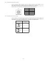
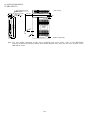
(2) Station number setting method
Set the station number with the station number switches (RSW1, RSW2) on the front
panel of the option unit MR-J2S-T01. The station numbers that can be set are 1 to 64
in decimal. In the initial status, the station number setting is 1.
RSW1
3
5
0
4
1
2
Set tens (Initial value: 0)
9
6
7
8
RSW2
3
5
0
4
1
2
Set units. (Initial value: 1)
9
6
7
8
CC-Link
master unit
PLC remote I/O
station
(1 station occupied)
3-5
3.2.4 Communication baudrate setting
Set the CC-Link transfer baudrate with the transfer baudrate switch (RSW3) on the
front panel of the option unit MR-J2S-T01. The initial setting is 156kbps.
The overall distance of the system changes depending on the set transfer speed. For
details, refer to the CC-Link System Master/Local Unit User's Manual.
No.
RSW3
0(Initial value) 156kbps
3
5
0
4
1
2
6
9
Baudrate
1
625kbps
2
2.5Mbps
3
5Mbps
4
10Mbps
7
5 to 9
Not used.
8
3.2.5 Occupied station count setting
Set the number of occupied stations with the occupied station count switch (SW1) the
front panel of the option unit MR-J2S-T01. The usable I/O signals and the number of
connectable units change depending on the set number of occupied stations.
SW1 Setting
OFF 1
OFF
2
OFF
Number of Occupied
Stations
1 station occupied
(Initial value)
OFF 1
OFF
2
ON
2 stations occupied
3-6
3.2.6 LED indications
The MR-J2S-T01 option unit has six LEDs. Their indications are indicated below.
L.RUN
SD
RD
L.ERR
S.ERR
WD
L.RUN
SD
LED
RD
: Turned on at normal receive of refresh data. Turned off when refresh data is
broken for a predetermined period.
: Turned on when send data is "0".
: Turned on when a carrier is detected in receive data.
: Turned on when the data addressed to the host is in CRC or abort error.
: Turned on when the servo amplifier is in an alarm status.
: Turned on when the CPU of the MR-J2S-T01 option unit becomes faulty.
Description
L.ERR
Normal communication is made but CRC error sometimes occurs due to
noise.
Normal communication
Hardware fault
Hardware fault
Receive data is in CRC error and response cannot be made.
Data addressed to the host does not arrive.
Hardware fault
Hardware fault
Polling response is made but refresh receive is in CRC error.
Hardware fault
Hardware fault
Hardware fault
Data addressed to the host is in CRC error.
Data addressed to the host does not exist or cannot be received due to
noise.
Hardware fault
Baudrate setting illegal.
Station number setting illegal.
Baudrate or station number setting changed midway (ERROR flickers for
about 0.4s).
Data cannot be received due to power off, power supply section fault, open
cable, etc.
LED
SERR WD
Servo amplifier in normal status
Servo amplifier in alarm status
Option unit in normal status
Option unit CPU in alarm status
*
*
: On
Description (as described above for L.RUN, SD, RD, L.ERR)
: Off
: Flicker *: Indefinite
3-7
3.3 Functions
3.3.1 Function block diagram
How I/O data are transferred to/from the servo amplifier in CC-Link will be described
using function blocks.
(1) Between the master station and servo amplifier in the CC-Link system, link refresh is
always made at 3.5 to 18ms (512 points). The link scan time for link refresh changes
depending on the communication speed. For details, refer to the CC-Link System
Master/Local Unit User's Manual.
(2) I/O refresh and master station's sequence program are executed asynchronously. Some
PLCs can synchronize the link scan with the sequence scan.
(3) Data read from the servo amplifier are read from the buffer memory of the CC-Link
system master/local unit using the FROM instruction, and data are written using the
TO instruction. Some PLCs allow the FROM/TO instructions to be omitted by setting
automatic refresh.
Servo amplifier
Input
Output
Servo amplifier CPU
Buffer
memory
3) Twisted pair
cable
(3-wire type)
I/O interface
CC-Link interface
2) Buffer memory read/write
CPU
Interface with PLC
PLC CPU
1) AJ61BT11
I/O signals
CC-Link interface
PLC CC-Link unit
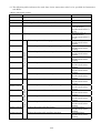
3.3.2 Functions
The following table indicates the functions that can be performed from the PLC in a
CC-Link system while the CC-Link or test operation mode is selected.
Operation Modes
Item
CC-Link operation mode
Monitor
Operation
Parameter write
Parameter read
Point table write
Point table read
3-8
Servo configuration software
test operation mode
(1) Operation mode
The MR-J2S-CP-S084 has the following operation modes.
1) Test operation mode
A servo motor is run with the amplifier front LED buttons.
2) CC-Link operation mode
A servo motor is run with a PLC program via the MR-J2S-T01 (CC-Link interface unit).
(2) Operation mode switching
(a) Operation mode switching conditions
Before operation mode switching, check that:
1) The servo motor is at a stop.
2) The forward or reverse rotation signal is OFF.
(b) Operation mode switching method
When switching from the test operation to the CC-Link operation, power off, then on the servo
amplifier to leave the test operation mode.
CC-Link
operation
mode
Symbol
A
Test operation
mode
A
Switching Type
CC-Link operation mode
Switching Method
Select the test operation mode with the
amplifier front LED button.
Test operation mode
3-9
3.4 Inputs/Outputs from/to the PLC CPU
3.4.1 I/O signals
The input signals can be used as either the CC-Link or CN1 external input signals. Make selection with parameter
Nos. 116, 117 and 118. The output signals can be used as both the CC-Link and CN1 external output signals
together.
(a) When one station is occupied (RX/RY: 32 points each, RWr/w: 4 points each)
PLC to Servo Amplifier (RY)
RYn0
Servo-on
RYn1
Forward rotation start
RYn2
Reverse rotation start
RYn3
Proximity dog
RYn4
Forward rotation stroke end
RYn5
Reverse rotation stroke end
RYn6
Automatic/manual selection
RYn7
Temporary stop/restart
RYn8
Monitor output execution demand
RYn9
Instruction code execution
demand
RYnA
Point table No. selection (bit 0)
RYnB
Point table No. selection (bit 1)
RYnC
Point table No. selection (bit 2)
RYnD
Point table No. selection (bit 3)
RYnE
Point table No. selection (bit 4)
RYnF
(Reserved)
RY(n 1)0
(Reserved)
RY(n 1)1
(Reserved)
RY(n 1)2
(Reserved)
RY(n 1)3
(Reserved)
RY(n 1)4
(Reserved)
RY(n 1)5
(Reserved)
RY(n 1)6
(Reserved)
RY(n 1)7
(Reserved)
RY(n 1)8
(Reserved)
RY(n 1)9
(Reserved)
RY(n 1)A
Reset
RY(n 1)B
(Reserved)
RY(n
RY(n
RY(n
RY(n
1)C
1)D
1)E
1)F
RXn0
RXn1
RXn2
RXn3
RXn4
RXn5
RXn6
RXn7
RXn8
RXn9
Servo Amplifier to PLC (RX)
Servo ready
In position
Rough match
Home position return completion
Limiting torque
(Reserved)
Electromagnetic brake interlock
Temporary stop
Monitoring
Instruction code execution
completion
Servo warning
Battery warning output
Movement finish
(Reserved)
Position range
RXnA
RXnB
RXnC
RXnD
RXnE
RXnF
RX(n 1)0
RX(n 1)1
RX(n 1)2
RX(n 1)3
RX(n 1)4
RX(n 1)5
RX(n 1)6
RX(n 1)7
RX(n 1)8
RX(n 1)9
RX(n 1)A
RX(n 1)B
(Reserved)
(Reserved)
(Reserved)
(Reserved)
RX(n
RX(n
RX(n
RX(n
PLC to Servo Amplifier (RWw)
RWwn
Monitor 1
RWwn 1
Monitor 2
RWwn 2
Instruction code
RWwn 3
Write the data
1)C
1)D
1)E
1)F
(Reserved)
(Reserved)
(Reserved)
(Reserved)
(Reserved)
(Reserved)
(Reserved)
(Reserved)
(Reserved)
(Reserved)
(Reserved)
Trouble
Remote bureau communication
ready
(Reserved)
(Reserved)
(Reserved)
(Reserved)
Data from Servo to PLC (RWr)
RWrn
Monitor 1 data
RWrn 1
Monitor 2 data
RWrn 2
Answer code
RWrn 3
Read the data
Note 1: The following signal is used for external I/O only.
1) External emergency stop signal (DI: EMG)
Note 2: n: depends on the station number setting.
3-10
(b) When two stations are occupied (RX/RY: 32 points each (can be increased to up to 64 points), RWr/w: 8
points each)
RYn0
RYn1
RYn2
RYn3
RYn4
RYn5
RYn6
RYn7
RYn8
RYn9
PLC to Servo Amplifier (RY)
Servo-on
Forward rotation start
Reverse rotation start
Proximity dog
Forward rotation stroke end
Reverse rotation stroke end
Automatic/manual selection
Temporary stop/restart
Monitor output execution demand
Instruction code execution demand
RXn0
RXn1
RXn2
RXn3
RXn4
RXn5
RXn6
RXn7
RXn8
RXn9
RYnA
RYnB
RYnC
RYnD
RYnE
RYnF
Point table No. selection (bit 0)
Point table No. selection (bit 1)
Point table No. selection (bit 2)
Point table No. selection (bit 3)
Point table No. selection (bit 4)
(Reserved)
RxnA
RXnB
RXnC
RXnD
RxnE
RXnF
to
RY(n 1)0
to
RY(n 2)0
(Reserved)
(Reserved)
(Reserved)
Position instruction demand
to
RX(n 1)0
to
RX(n 2)0
RY(n 2)1
Speed instruction demand
RY(n
RY(n
RY(n
RY(n
RY(n
2)2
2)3
2)4
2)5
2)6
RY(n
RY(n
RY(n
RY(n
2)7
2)8
2)9
2)A
(Reserved)
(Reserved)
(Reserved)
(Reserved)
Internal torque limit selection
(second selection)
Proportion control
Gain switch selection
(Reserved)
Position/speed designation system
selection
Absolute value/incremental value
selection
(Reserved)
(Reserved)
(Reserved)
(Reserved)
Reset
(Reserved)
RY(n 2)B
to
RY(n 3)0
to
RY(n 3)9
RY(n 3)A
RY(n 3)B
RY(n
RY(n
RY(n
RY(n
3)C
3)D
3)E
3)F
*1
*1
Servo Amplifier to PLC (RX)
Servo ready
In position
Rough match
Home position return completion
Limiting torque
(Reserved)
Electromagnetic brake interlock
Temporary stop
Monitoring
Instruction code execution
completion
Servo warning
Battery warning output
Movement finish
(Reserved)
Position range
(Reserved)
RX(n 2)1
(Reserved)
(Reserved)
(Reserved)
(Reserved)
RX(n
RX(n
RX(n
RX(n
RX(n
2)2
2)3
2)4
2)5
2)6
RX(n
RX(n
RX(n
RX(n
2)7
2)8
2)9
2)A
(Reserved)
(Reserved)
(Reserved)
(Reserved)
RX(n 2)B
(Reserved)
to
RX(n 3)0
to
RX(n 3)9
RX(n 3)A
RX(n 3)B
(Reserved)
(Reserved)
(Reserved)
(Reserved)
RX(n
RX(n
RX(n
RX(n
*1: Select the instruction system using parameter No. 41.
Note 1: n: depends on the station number setting.
3-11
(Reserved)
(Reserved)
(Reserved)
Position instruction execution
completion
Speed instruction execution
completion
Point table No. output bit 0
Point table No. output bit 1
Point table No. output bit 2
Point table No. output bit 3
Point table No. output bit 4
3)C
3)D
3)E
3)F
Trouble
Remote bureau communication
ready
(Reserved)
(Reserved)
(Reserved)
(Reserved)
PLC to Servo Amplifier (RWw)
Monitor 1
*1
1
Monitor 2
*1
2
Instruction code
3
Write the data
4
Position instruction data under
16 bits/point No.
*2
RWwn 5
Position instruction data upper
16 bits
RWwn 6
Speed instruction data/point No.
*3
RWwn 7
(Reserved)
RWwn
RWwn
RWwn
RWwn
RWwn
RWrn
RWrn
RWrn
RWrn
RWrn
Data from Servo to PLC (RWr)
Monitor 1 data under 16 bits
1
Monitor 1 data upper 16 bits
2
Answer code
3
Read the data
4
RWrn 5
Monitor 2 data under 16 bits
RWrn 6
Monitor 2 data upper 16 bits
RWrn 7
(Reserved)
Note 1: n: depends on the station number setting.
*1: For the monitor code of 32-bit data, specify its under 16 bits.
If the upper 16 bits are specified, only the upper 16-bit data of the 32-bit data can be monitored.
*2: Specify the point table No. at RWw4 when Pr. 41 =
0, or the position data at RWw4 and RWw5
when Pr. 41 =
1 or
2, and turn on Position instruction execution demand (RY(n 2)0).
1, or the speed data at RWw6 when Pr. 41 =
*3: Specify the point table No. at RWw6 when Pr. 41 =
2, and turn on Speed instruction execution demand (RY(n 2)1). The RWw6 value is not used
when Pr. 41 =
0.
3-12
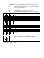
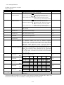
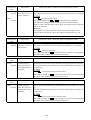
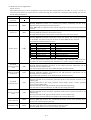
3.4.2 I/O signal details
(1) When one station is occupied
<Input signals>
Device No.
RYn0
RYn1
RYn2
RYn3
RYn4
RYn5
RYn6
RYn7
RYn8
RYn9
RYnA
RYnB
RYnC
RYnD
RYnE
RY(n 1)A
Signal Name
Servo-on
Description
OFF: Invalid
ON: Operation ready (base circuit ON)
Start (Forward
Manual operation
OFF: Stop command
rotation start)
ON: Forward rotation start
Automatic operation
Leading edge: Forward rotation start
During temporary stop OFF to ON: Operation restart
(movement by remaining distance)
Start (Reverse
Manual operation
OFF: Stop command
rotation start)
ON: Forward rotation start
Automatic operation
Leading edge: Forward rotation
start (invalid for positioning ABS)
During temporary stop OFF to ON: Operation restart
(movement by remaining distance)
Proximity dog
OFF: Valid
ON: Invalid
Forward rotation OFF: Outside stroke range
stroke end
ON: Inside stroke range
Reverse rotation OFF: Outside stroke range
stroke end
ON: Inside stroke range
Automatic/manual OFF: Manual operation
selection
ON: Automatic operation
Temporary
OFF to ON during operation: Temporary stop
stop/restart
When Monitor output execution demand (RYnC) is turned
Monitor output
execution demand on, monitor values are set to remote registers
RWrn/RWrn 1 and RWrn 5/RWrn 6, Monitoring (RXnC)
turns on, and a normal or error code is set to Answer code
(RWrn 2). While Monitor output execution demand
(RYnC) is on, the monitor values are always updated.
When Instruction code execution demand is turned on, the
Instruction code
execution demand processing corresponding to the instruction code set to
RWwn 2 is executed. After completion of the instruction
code, Instruction code execution completion (RXnD) turns
on. At that time, a normal or error code is set to Answer
code (RWrn 2).
For point table No. selection, choose the 31-point table No.
Point table
with a 5-bit binary value.
selection
bit 0
Point table RYn5
RYn4 Ryn3 RYn2 RYn1
Point table
No.
selection
0
0
0
0
0
0
bit 1
1
0
0
0
0
1
Point table
2
0
0
0
1
0
selection
3
0
0
0
1
1
bit 2
4
0
0
1
0
0
Point table
:
selection
bit 3
29
1
1
1
0
1
Point table
30
1
1
1
1
0
selection
31
1
1
1
1
1
bit 4
Reset
OFF: Invalid
ON: Reset
*1 External DI/CC-Link device selection can be made by setting parameter No. 116 to 118.
*2 Internal automatic ON is enabled by setting parameter No. 84 to 86.
3-13
Remarks
*1
*1
*1
*1
*1
*2
*1
*2
*1
*2
*1
*1
*2
*1
*2
*1
*2
*1
*2
*1
*2
*1
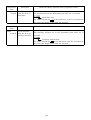
<Output signals>
Device No.
RXn0
Signal Name
Servo ready
RXn1
RXn2
In position
Rough match
RXn3
Home position
return completion
Limiting torque
RXn4
RXn6
RXn7
RXn8
RXn9
Electromagnetic
brake interlock
Temporary stop
RXnA
RXnB
Monitoring
Instruction code
execution
completion
Servo warning
Battery warning
RXnC
Movement finish
RXnE
Position range
RX(n 1)A
Trouble
RX(n 1)B
Remote bureau
communication
ready
Description
Turns on when the servo amplifier is ready to operate
after servo-on.
Turns on at an in-position time.
Turns on when the preset rough match output range is
reached.
Turns on at completion of a home position return.
Turns on when the servo motor torque limit region is
reached.
Normally on, turns off when the electromagnetic brake
operates.
Turns on when operation is stopped by the temporary stop
signal.
Output when deceleration to a temporary stop starts.
Refer to Monitor output execution demand.
Refer to Instruction code execution demand.
Normally on, turns off at servo warning occurrence.
Turns on when an open battery cable warning (AL92) or
battery warning (AL9F) occurs.
Turns on when an in-position output is provided and the
position instruction remaining distance is zero.
Turns on when the actual current position falls within the
range set in the parameter. Does not turn on when a home
position return is not completed or the base circuit is off.
Normally off, turns on at servo alarm occurrence.
Turns on also at an emergency stop when the external
dynamic brake has been selected. (The alarm definition is
returned as an alarm code.)
Turns on also at warning occurrence when the prealarm
output is made valid.
Normally on, turns off at servo alarm occurrence or a
reset.
3-14
Remarks
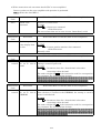
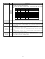
(2) When two stations are occupied
<Input signals>
Device No.
RYn0
RYn1
RYn2
RYn3
RYn4
RYn5
RYn6
RYn7
RYn8
RYn9
RYnA
RYnB
RYnC
RYnD
RYnE
Signal Name
Servo-on
Description
OFF: Invalid
ON: Operation ready (base circuit ON)
Start
Manual operation
OFF: Stop command
(Forward rotation
ON: Forward rotation start
start)
Automatic operation
Leading edge: Forward rotation start
During temporary stop OFF to ON: Operation restart
(movement by remaining distance)
Start
Manual operation
OFF: Stop command
(Reverse rotation
ON: Forward rotation start
start)
Automatic operation
Leading edge: Forward rotation
start (invalid for positioning ABS)
During temporary stop OFF to ON: Operation restart
(movement by remaining distance)
Proximity dog
OFF: Valid
ON: Invalid
Forward rotation
OFF: Outside stroke range
stroke end
ON: Inside stroke range
Reverse rotation
OFF: Outside stroke range
stroke end
ON: Inside stroke range
Automatic/manual OFF: Manual operation
selection
ON: Automatic operation
Temporary
OFF to ON during operation: Temporary stop
stop/restart
Monitor output
When Monitor output execution demand (RYnC) is turned
execution demand on, monitor values are set to remote registers
RWrn/RWrn 1 and RWrn 5/RWrn 6, Monitoring (RXnC)
turns on, and a normal or error code is set to Answer code
(RWrn 2). While Monitor output execution demand
(RYnC) is on, the monitor values are always updated.
Instruction code
When Instruction code execution demand is turned on, the
execution demand processing corresponding to the instruction code set to
RWwn 2 is executed. After completion of the instruction
code, Instruction code execution completion (RXnD) turns
on. At that time, a normal or error code is set to Answer
code (RWrn 2).
For point table No. selection, choose the 31-point table No.
Point table
with a 5-bit binary value.
selection
bit 0 Point table RYn5 RYn4 RYn3 RYn2 RYn1
No.
Point table
selection
0
0
0
0
0
0
bit 1
1
0
0
0
0
1
Point table
2
0
0
0
1
0
selection
3
0
0
0
1
1
bit 2
4
0
0
1
0
0
Point table
:
selection
29
1
1
1
0
1
bit 3
30
1
1
1
1
0
Point table
31
1
1
1
1
1
selection
bit 4
*1 External DI/CC-Link device selection can be made by setting parameter No. 116 to 118.
*2 Internal automatic ON is enabled by setting parameter No. 84 to 86.
3-15
Remarks
*1
*1
*1
*1
*1
*2
*1
*2
*1
*2
*1
*1
*2
*1
*2
*1
*2
*1
*2
*1
*2
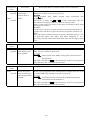
Device No.
RY(n 2)0
RY(n 2)1
RY(n
RY(n
RY(n
RY(n
RY(n
2)2
2)3
2)4
2)5
2)6
RY(n 1)7
RY(n 1)8
RY(n 2)9
RY(n 2)A
RY(n 2)B
RY(n 3)A
Signal Name
Description
Position instruction When Pr. 41 =
0, set the point table No. to RWw4 and
demand
turn on Position instruction demand.
When Pr. 41 =
1 or
2, set the position
instruction data to RWw4 and RWw5 and turn on Position
instruction demand.
When data is secured, Position instruction execution
completion (RX(n 2)0) turns on.
At that time, a normal or error code is set to Answer code
(RWr2).
The secured data is made valid from the next automatic
operation.
Speed instruction When Pr. 41 =
0, the RWw6 value is not used if the
demand
demand is turned on.
When Pr. 41 =
1, set the point table No. to RWw6 and
turn on Speed instruction demand.
When Pr. 41 =
2, the speed instruction data to RWw6
and turn on Speed instruction demand.
When data is secured, Speed instruction execution
completion (RX(n 2)1) turns on.
At that time, a normal or error code is set to Answer code
(RWr2).
The secured data is made valid from the next automatic
operation.
(Reserved)
(Reserved)
(Reserved)
(Reserved)
Internal torque
OFF: Limits to the Pr. 28 setting.
limit selection
ON: Limits torque to the lower value of the Pr. 28 and Pr.
29 settings.
Proportion control OFF: The speed amplifier is of proportion integral type.
ON: The speed amplifier is of proportion type.
Gain switch
Turned on to make the switch gain valid when the gain
selection
switch selection has been set to the input signal in
parameter No. 68 (CDP).
(Reserved)
Position/speed
OFF: Point table
designation
ON: Position instruction
system selection
Absolute value/
Select the absolute or incremental value for operation
incremental value when the command mode selected in Pr. 0 is the absolute
selection
value command.
OFF: Absolute value
ON: Incremental value
Reset
OFF: Invalid
ON: Reset
*1 External DI/CC-Link device selection can be made by setting parameter No. 116 to 118.
*2 Internal automatic ON is enabled by setting parameter No. 84 to 86.
3-16
Remarks
*1
*1
*2
*1
Parameter No. 2
When absolute
value command
is given
*1
<Output signals>
Device No.
RXn0
Signal Name
Servo ready
RXn1
RXn2
In position
Rough match
RXn3
Home position
return completion
Limiting torque
RXn4
RXn6
RXn7
RXn8
RXn9
RXnA
RXnB
RXnC
RXnE
RX(n 2)0
RX(n 2)1
RX(n 2)2
RX(n 2)3
RX(n 2)4
RX(n 2)5
RX(n 2)6
Electromagnetic
brake interlock
Temporary stop
Monitoring
Instruction code
execution
completion
Servo warning
Battery warning
Description
Turns on when the servo amplifier is ready to operate
after servo-on.
Turns on at an in-position time.
Turns on when the preset rough match output range is
reached.
Turns on at completion of a home position return.
Remarks
Turns on when the servo motor torque limit region is
reached.
Normally on, turns off when the electromagnetic brake
operates.
On from when operation is stopped by the temporary stop
signal (from start of deceleration to a temporary stop)
until a restart is made by the temporary stop signal.
Refer to Monitor output execution demand.
Refer to Instruction code execution demand.
Normally on, turns off at servo warning occurrence.
Turns on when an open battery cable warning (AL92) or
battery warning (AL9F) occurs.
Movement finish
Turns on when an in-position output is provided and the
position instruction remaining distance is zero.
Position range
Turns on when the actual current position falls within the
range set in the parameter. Does not turn on when a home
position return is not completed or the base circuit is off.
Position instruction Refer to Position instruction demand.
execution
completion
Speed instruction Refer to Speed instruction demand.
execution
completion
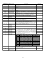
The point table No. is output at completion of positioning.
Point table No.
Off at power-on, at servo-off, during home position return,
output bit 0
or at home position return completion. The previous
Point table No.
output state is maintained when the automatic/manual
output bit 1
mode selection (MD0) is switched from the automatic
Point table No.
mode to the manual mode or from the manual mode to the
output bit 2
automatic mode, during manual operation, or during highPoint table No.
speed home position return.
output bit 3
Point table No.
RX(n 2)6 RX(n 2)5 RX(n 2)4 RX(n 2)3 RX(n 2)2 Output Point Table No.
output bit 4
OFF
OFF
OFF
OFF
OFF
OFF
OFF
OFF
OFF
RX(n 3)A
Trouble
RX(n 3)B
Remote bureau
communication
ready
OFF
OFF
OFF
OFF
OFF
OFF
OFF
ON
OFF
ON
ON
OFF
ON
OFF
ON
OFF
Point Table No.1
Point Table No.2
Point Table No.3
Point Table No.4
to
to
to
to
to
to
ON
ON
ON
ON
ON
ON
ON
ON
ON
ON
ON
ON
ON
ON
OFF
OFF
OFF
ON
ON
ON
ON
OFF
ON
ON
OFF
OFF
ON
ON
ON
OFF
ON
OFF
ON
OFF
ON
Point Table No.25
Point Table No.26
Point Table No.27
Point Table No.28
Point Table No.29
Point Table No.30
Point Table No.31
Normally off, turns on at servo alarm occurrence.
Turns on also at warning occurrence when the prealarm
output is made valid.
Normally on, turns off at servo alarm occurrence or a
reset.
3-17
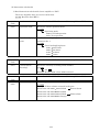
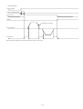
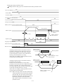
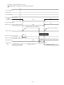
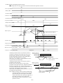
3.4.3 Data Communication Timing Chart
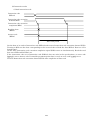
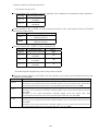
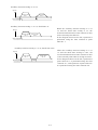
(1) Monitor codes
1) When one station is occupied
Monitor 1 code
(RWw0)
Monitor 2 code
(RWw1)
Monitor execution
demand (RY8)
Monitoring
(RX8)
Monitor 1 data
(RWr0)
Monitor 2 data
(RWr1)
Answer code
(RWr2)
Data held
Set monitor codes to Monitor 1 (RWw0) and Monitor 2 (RWw1), and turn on Monitor output execution
demand (RY8). Turning on RY8 sets the following data. Data are all in hexadecimal. At this time,
Monitoring (RXC) turns on simultaneously.
Monitor data 1 (RWr0): Data demanded by Monitor 1 (RWw0)
Monitor data 2 (RWr1): Data demanded by Monitor 2 (RWw1)
For 32-bit data, set the under 16 bits of the monitor code to Monitor 1 (RWw0) and the upper 16 bits to
Monitor 2 (RWw1), and read them simultaneously.
The monitor data set to the registers are continuously updated while RX8 is on. When RX8 turns off, the
data set to Monitor data RWr0, RWr1 are held.
If the monitor code set to either or both of Monitor 1 (RWw0) and Monitor 2 (RWw1) does not exist in the
specifications, an error code (
1) is set to Answer code.
3-18
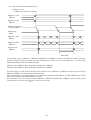
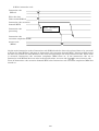
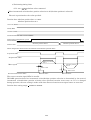
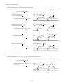
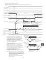
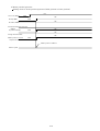
2) When two stations are occupied
Monitor 1 code
(RWw0)
Monitor 2 code
(RWw1)
Monitor execution
demand (RY8)
Monitoring
(RX8)
Monitor 1 data
Under 16 bits
(RWr0)
Monitor 1 data
Upper 16 bits
(RWr1)
Monitor 2 data
Under 16 bits
(RWr5)
Monitor 2 data
Upper 16 bits
(RWr6)
Answer code
(RWr2)
Data held
Set monitor codes to Monitor 1 (RWw0) and Monitor 2 (RWw1), and turn on Monitor output execution
demand (RY8). Turning on RY8 sets the following data. For all 32-bit data, set the upper 16 bits and
under 16 bits separately to the registers. Data are all in hexadecimal. At this time, Monitoring (RX8)
turns on simultaneously.
Monitor data 1 under 16 bits (RWr0): Under 16 bits of data demanded by Monitor 1 (RWw0)
Monitor data 1 upper 16 bits (RWr1): Upper 16 bits of data demanded by Monitor 1 (RWw0)
Monitor data 2 under 16 bits (RWr5): Under 16 bits of data demanded by Monitor 2 (RWw1)
Monitor data 2 upper 16 bits (RWr6): Upper 16 bits of data demanded by Monitor 2 (RWw1)
If data does not exist at RWr1/RWr6, a sign is set. " " indicates "0000" and " " "FFFF".
The monitor data set to the registers are continuously updated while RX8 is on. When RX8 turns off, the
data set to Monitor data RWr0, RWr1, RWr5, RWr6 are held.
If the monitor code set to either or both of Monitor 1 (RWw0) and Monitor 2 (RWw1) does not exist in the
specifications, an error code (
1) is set to Answer code.
3-19
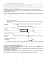
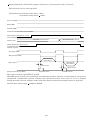
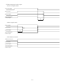
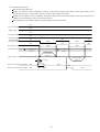
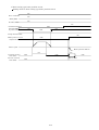
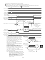
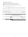
(2) Instruction codes
1) Read instruction code
Instruction code
(RWw2)
Instruction code execution
demand (RY9)
Instruction code execution
completion (RX9)
Read the data
(RWr3)
Answer code
(RWr2)
Data read period
Set the data to be read to Instruction code (RWw2) and turn on Instruction code execution demand (RY9).
Turning on RY9 sets the data corresponding to the set read code to Read the data (RWr3). Data are all in
hexadecimal.
At this time, Instruction code execution completion signal (RX9) turns on simultaneously. Read the read
data set to RWr3 while RX9 is on.
If the instruction code set to Instruction code (RWw2) does not exist in the specifications, an error code
(
1 ) is set to Answer code. If unusable parameter/point data is read, an error code (
2 ) is set.
Turn off Instruction code execution demand (RY9) after completion of data read.
3-20
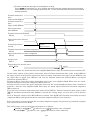
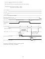
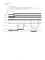
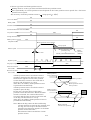
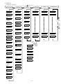
2) Write instruction code
Instruction code
(RWw2)
Write the data
Under 16 bits (RWw3)
Instruction code execution
demand (RYD)
Instruction code
processing
Write execution
processing
Instruction code
execution completion (RXD)
Answer code
(RWr2)
Set the write instruction code to Instruction code (RWw2) and the data to be written (data to be executed)
to Write the data (RWw3), and turn on Instruction code execution demand (RY9). Turning on RY9 writes
the data set to Write the data (RWw3) to the item corresponding to the write instruction code. When write
is executed, Instruction code execution completion (RX9) turns on. If the instruction code set to
Instruction code (RWw2) does not exist in the specifications, an error code (
1 ) is set to Answer code.
Turn off Instruction code execution demand (RY9) after Instruction code execution completion (RX9) has
turned on.
3-21
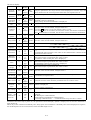
(3) Setting of position/speed using remote register
When the manual/automatic selection signal is automatic, choosing Point table No./direct designation
changing selection for direct designation selects the direct designation mode.
The direct designation mode has three designation systems: point table No. designation, position
instruction and speed/acceleration/deceleration point No. designation, and position/speed instruction. Set
the designation system in parameter No. 41.
When direct designation is selected, the point table No. selection device of the RY devices is invalid.
If Manual/automatic selection is changed to manual during operation, the direct designation operation is
suspended and the motor stops.
When the command system is the absolute value command, INC/ABS operation selection can be made using
absolute value/incremental value selection signal. ABS operation is performed when absolute value/incremental
value selection signal is off and INC operation is performed when the signal is on. Operation depends on the
state of absolute value/incremental value selection signal when the start signal turns on.
When the command system is the incremental value command, absolute value/incremental value
selection signal is invalid.
1) When point table No. is set
0 (initial value) in parameter No. 41 to validate operation by specifying the point
Preset
table No.
Point table
No.(RWw4)
Position instruction demand
(RY10)
Point table
No. designation
(Note)
Data secured
Position instruction
execution completion (RX10)
Answer code
(RWr2)
Forward/reverse rotation start
(RYA RYB)
5msec
Note. Data are stored into the servo amplifier RAM. Hence, they are erased if power is switched off.
Set the point table No. to Point table No. (RWw4) and turn on Position instruction demand (RY10).
Turning on RY10 stores the position instruction, speed instruction, acceleration/deceleration time
constant of the specified point table No. into the servo amplifier RAM. When they are stored, Position
instruction execution completion (RX10) turns on.
If any data set to Point table No. (RWw4) is outside the setting range, an error code ( 3
) is set to
Answer code. The point table No. is 1 to 31.
Turn on Forward rotation start (RY10)/Reverse rotation start (RYB) after Position instruction execution
completion (RX10) has turned on.
If the start signal is turned on with the execution completion signal off, operation is performed using the
data currently stored in the RAM.
When the point table No. is remote register, the point table auxiliary function is made invalid.
3-22
2) Direct command data setting/point table No. (speed command) setting
Preset
1 in parameter No. 41 to validate operation using the speed and acceleration/
deceleration of the position instruction data/point No.
Manual/automatic selection
Position instruction
data
Under 16 bits (RWw4)
Position instruction
data
Upper 16 bits (RWw5)
Point No.
(RWw6)
Position instruction demand
(RY10)
Speed instruction demand
(RY11)
Position/speed data
setting
(Note)
Data secured
Position instruction execution completion
(RX10)
Speed instruction execution completion
(RX10)
Answer code
(RWr2)
Forward/reverse rotation start
(RYA RYB)
5msec
Note. Data are stored into the servo amplifier RAM. Hence, they are erased if power is switched off.
Set the under 16 bits of the position instruction data to Position instruction data under 16 bits (RWw4),
the upper 16 bits of the position instruction data to Position instruction data upper 16 bits (RWw5), and
the point No. to Point No. (RWw6), and turn on Position instruction demand (RY10) and Speed
instruction demand (RY11).
Turning on RY10 stores the position instruction data to the servo amplifier RAM. When they are stored,
Position instruction execution completion (RX10) turns on.
Turning on RY11 stores the speed data and acceleration/deceleration data of the specified point No. into
the servo amplifier RAM. When they are stored, Speed instruction execution completion (RX11) turns on.
If any data set to Position instruction data under 16 bits (RWw4), Position instruction data upper 16 bits
(RWw5) and Point No. (RWw6) is outside the setting range, an error code is set to Answer code.
Turn on Forward rotation start (RY10)/Reverse rotation start (RYB) after Position instruction execution
completion (RX10) and Speed instruction execution completion (RX11) have turned on.
If the start signal is turned on with the execution completion signals off, operation is performed using the
data currently stored in the RAM.
3-23
3) Position command data/speed command data setting
Preset
2 in parameter No. 41 to validate operation using the position instruction data/speed
instruction data. Use the setting of point table No. 1 as the acceleration/deceleration time constant
during operation.
Position instruction
data
Under 16 bits (RWw4)
Position instruction
data
Upper 16 bits (RWw5)
Speed instruction
data (RWw6)
Position instruction demand
(RY10)
Speed instruction demand
(RY11)
Position/speed data
setting
(Note)
Data secured
Position instruction execution completion
(RX10)
Speed instruction execution completion
(RX10)
Answer code
(RWr2)
Forward/reverse rotation start
(RYA RYB)
5msec
Note. Data are stored into the servo amplifier RAM. Hence, they are erased if power is switched off.
Set the under 16 bits of the position instruction data to Position instruction data under 16 bits (RWw4),
the upper 16 bits of the position instruction data to Position instruction data upper 16 bits (RWw5), and
the speed data to Speed data (RWw6), and turn on Position instruction demand (RY10) and Speed
instruction demand (RY11).
Turning on RY10 stores the position instruction data to the servo amplifier RAM. When they are stored,
Position instruction execution completion (RX10) turns on.
Turning on RY11 stores the speed instruction data and the acceleration/deceleration time constant of
point No. 1 into the servo amplifier RAM. When they are stored, Speed instruction execution completion
(RX11) turns on.
If any data set to Position instruction data under 16 bits (RWw4), Position instruction data upper 16 bits
(RWw5) and Speed instruction data (RWw6) is outside the setting range, an error code is set to Answer
code.
Turn on Forward rotation start (RY10)/Reverse rotation start (RYB) after Position instruction execution
completion (RX10) and Speed instruction execution completion (RX11) have turned on.
If the start signal is turned on with the execution completion signals off, operation is performed using the
data currently stored in the RAM.
The setting range of the position instruction data is as follows:
999999 to 999999 10STM m when Pr. 00 =
0 (absolute value command)
STM
0 to 999999 10
m when Pr. 00 =
1 (incremental value command)
3-24
(4) Remote register positioning operation
1) Parameter setting items
Using parameter No. 00 (STY), select the absolute value command or incremental value command.
Setting
Positioning System
0
Absolute value
command
1
Incremental value
command
Using parameter No. 1 (FTY), set the rotation direction of the start signal based on Forward
rotation start signal (ST1).
Setting
Rotation Direction
0
Rotation in CCW direction with
address increase
1
Rotation in CW direction with
address increase
Using parameter No. 1 (FTY), set the command unit.
Setting
Command Unit
Travel
0
1-time pulse selection
1[ m]
1
10-time pulse
10[ m]
selection
2
100-time pulse
100[ m]
selection
3
1000-time pulse
1000[ m]
selection
2) Position/speed designation system using remote register
Using the remote register of CC-Link, save the position, speed and acceleration/deceleration time
constant into the RAM.
Pr.41
Position/speed designation system using remote register
0
Point table No. designation
1
2
Turning on the position instruction demand signal saves the position data, speed data
and acceleration/deceleration data of the specified point table No. into the RAM.
Directly designated data setting/point table No. (speed command) setting
Turning on the position instruction demand signal saves the position instruction into
the RAM.
Turning on the speed instruction demand signal saves the speed data and
acceleration/deceleration data of the specified point table No. into the RAM.
Position command data/speed command data setting
Turning on the position instruction demand signal saves the position instruction into
the RAM.
Turning on the speed instruction demand signal saves the speed instruction and the
acceleration/deceleration data of point table No. 1 into the RAM.
3-25
3) Positioning timing chart
a) Pr. 00 =
0 , absolute value command
When incremental value/absolute position selection is off (absolute position is selected)
The axis is positioned at the value specified.
Position data: Absolute position data 1: 10000
Absolute position data 2: 0
Servo-on (SON)
Ready (RD)
Trouble (ALM)
Automatic/manual mode selection (MD0)
Position/speed designation system
selection(CSL)
Position data
Absolute position data 1
Absolute position data 2
Direct designation selection-time incremental value/absolute position (INC)
In position (INP)
Rough match (CPO)
Absolute position
data 1
Motor speed
Absolute position
data 2
5msec or less
5msec or less
Forward rotation start (ST1)
8msec or more
8msec or more
The reverse rotation signal (ST2) is invalid.
INC/ABS operation based on incremental value/absolute position selection is determined by the state of
incremental value/absolute position selection when Forward rotation start turns on. If it is changed
during operation, the new setting is made valid when Forward rotation start signal turns on next time.
Position data setting range:
999999 to 999999
3-26
When incremental value/absolute position selection is on (incremental value is selected)
The axis moves by the value specified.
Position data: Incremental value data 1: 10000
Incremental value data 2: 10000
Servo-on (SON)
Ready (RD )
Trouble (ALM)
Automatic/manual mode selection (MD0)
Position/speed designation system
selection(CSL)
Position data
Incremental value data 1
Incremental value data 2
Direct designation selection-time
incremental value/
absolute position
In position (INP)
Rough match (CPO)
Incremental
value data 1
Motor speed
5msec or less
Incremental
value data 2
5msec or less
Forward rotation start (ST1)
8msec or more
8msec or more
The reverse rotation signal (ST2) is invalid.
INC/ABS operation based on incremental value/absolute position selection is determined by the state of
incremental value/absolute position selection when Forward rotation start turns on. If it is changed
during operation, the new setting is made valid when Forward rotation start signal turns on next time.
Position data setting range:
999999 to 999999
3-27
b) Pr. 00 =
1 , incremental value command
The axis moves in the start signal direction by the value specified.
Position data: Incremental value data 1: 10000
Incremental value data 2: 10000
Servo-on (SON)
Ready (RD)
Trouble (ALM)
Automatic/manual mode selection (MD0)
Position/speed designation system
selection (CSL)
Position data
Incremental value data 1
Incremental value data 2
Direct designation selection-time incremental
value/absolute
position
In position (INP)
Rough match (CPO)
Incremental
value data 1
Motor speed
5msec or less
Forward rotation start (ST1)
Incremental
value data 2
8msec or more
5msec or less
Reverse rotation start (ST2)
8msec or more
Incremental value/absolute position selection is invalid.
Position data setting range: 0 to 999999
3-28
3.4.4 Remote register RWw setting ranges
RWW
RWwn
RWwn 1
RWwn 2
RWwn 3
RWwn 4
RWwn 5
RWwn 6
RWwn 7
Description
Monitor code 1
Monitor code 2
Instruction code
Write code
Setting Range
0000 to 001D
0000 to 001D
Those given in the instruction code list
Refer to the instruction code details.
Refer to the corresponding details for the
parameters and position/speed blocks.
Position instruction data Pr. 00 =
0
under 16 bits
: Position instruction 999999 to 999999
1
Position instruction data Pr. 00 =
: Position instruction 0 to 999999
upper 16 bits
Speed instruction data
Speed instruction: 0 to permissible speed
(Reserved)
(Reserved)
3-29
3.5 Communication Codes
3.5.1 Monitor codes
Monitor code list
The following table indicates the word data (monitor codes) to be specified for Monitor 1 code RWw0
and Monitor 2 code RWw1.
Monitor Data
Code No.
Reply Data (Servo Amplifier to PLC) Remarks
Data
Unit
When 1
When 2
length
stations
station is
occupied
are
occupied
0000
0000
No monitor
0000
0001
0001
Current position under 16 bits
16bit
0002
Current position upper 16 bits
16bit
0003
0003
Command position under 16 bits
16bit
0004
Command position upper 16 bits
16bit
10STM [mm]
0005
0005
Command remaining distance
16bit
under 16 bits
0006
Command remaining distance
16bit
upper 16 bits
0007
0007
No monitor
16bit
0008
0008
Point table
16bit
[No.]
0009
No monitor
16bit
000A
000A
Cumulative feedback pulses
16bit
[pulse]
under 16 bits
000B
Cumulative feedback pulses
16bit
[pulse]
upper 16 bits
000C
No monitor
16bit
000D
No monitor
16bit
000E
000E
Droop pulses under 16 bits
16bit
[pulse]
000F
Droop pulses upper 16 bits
16bit
[pulse]
0010
0010
Torque limit command voltage
16bit
0.01[V]
0011
0011
Regenerative load ratio
16bit
[%]
0012
0012
Effective load ratio
16bit
[%]
0013
0013
Peak load ratio
16bit
[%]
0014
0014
Instantaneous torque
16bit
[%]
0015
0015
ABS counter
16bit
[rev]
0016
0016
Motor speed under 16 bits
16bit
0.1[r/min]
0017
Motor speed upper 16 bits
16bit
0.1[r/min]
0018
0018
Bus voltage
16bit
[V]
0019
0019
ABS position under 16 bits
16bit
[pulse]
001A
ABS position middle 16 bits
16bit
[pulse]
001B
001B
ABS position upper 16 bits
16bit
[pulse]
001C
001C
Within one-revolution position
16bit
[pulse]
under 16 bits
001D
Within one-revolution position
16bit
[pulse]
upper 16 bits
*The multiplying factor of the monitor data can be read with the instruction code (from 0101H on).
3-30
3.5.2 Monitor data
Read the data, which were demanded by Monitor code 1 and Monitor code 2, from Monitor data 1 RWr0
and Monitor data 2 RWr1.
(1) Monitor data reading method
Refer to the monitor code execution timing chart in Section 3.4.3 (1).
3.5.3 Instruction codes
Instruction code list
The following table indicates the word data (read instruction codes) to be specified for Instruction
code RWw2.
Point table
<Read instruction codes>
Code No.
Item
0000
Operation mode reading
0002
Travel multiplying factor reading
0010
Current alarm (warning) reading
0020 to 0025 Alarm history 0 to 5 reading
0030 to 0035 Alarm occurrence time 0 to 5 in alarm history
0040
Input status reading 0
0041
Input status reading 1
0042
Input status reading 2
0050
Output status reading 0
0051
Output status reading 1
0052
Output status reading 2
0081
Energization time reading
0082
Power ON frequency reading
00A0
Ratio of load inertia moment reading
00B0
Within-1-revolution position data reading under 16 bits
00B1
Within-1-revolution position data reading upper 16 bits
00B2
Multi-revolution data reading
00C0
Error parameter No./Point table No. reading
0100 to 011D Monitor multiplying factor reading
0200 to 027C Parameter No. 00 to 124 data reading
0300 to 037C Reads the parameter No. 00 to 124 data format
0400 to 041F
Reads the point table target position under 16 bits
0500 to 051F
Reads the point table target position upper 16 bits
0600 to 061F
Reads the point table motor speed
0700 to 071F
Reads the point table acceleration time constant
0800 to 081F
Reads the point table deceleration time constant
0900 to 091F
Reads the point table dwell time
0A00 to 0A1F
Reads the point table auxiliary function
3-31
Remarks
(1) The following table indicates the word data (write instruction codes) to be specified for Instruction
code RWw2.
<Write instruction codes>
Code No.
8000 to 800F Empty
Item
Remarks
8010
Alarm reset command
8101
Feedback pulse value display data is clear
8200 to 827C
Writes parameter No. 00 to 124 to RAM
8300 to 837C
Writes parameter No. 00 to 124 to EEPROM
Writes the point table target position under 16 bits
8500 to 851F
Writes the point table target position upper 16 bits
8600 to 861F
Writes the point table motor speed
8700 to 871F
8800 to 881F
Point table (RAM)
8400 to 841F
Writes the point table acceleration time constant
Writes the point table deceleration time constant
Writes the point table dwell time
8A00 to 8A1F
Writes the point table auxiliary function
8B00 to 8B1F
Writes the point table target position under 16 bits
8C00 to 8C1F
Writes the point table target position upper 16 bits
8D00 to 8D1F
8E00 to 8E1F
8F00 to 8F1F
9000 to 901F
9100 to 911F
Point table (EEP-ROM)
8900 to 891F
Writes the point table motor speed
Writes the point table acceleration time constant
Writes the point table deceleration time constant
Writes the point table dwell time
Writes the point table auxiliary function
3-32
Decimal value is
converted into
hexadecimal before it
is set.
Decimal value is
converted into
hexadecimal before it
is set.
Converted into
hexadecimal before
setting.
Converted into
hexadecimal before
setting.
Converted into
hexadecimal before
setting.
Converted into
hexadecimal before
setting.
Converted into
hexadecimal before
setting.
Converted into
hexadecimal before
setting.
Converted into
hexadecimal before
setting.
Converted into
hexadecimal before
setting.
Converted into
hexadecimal before
setting.
Converted into
hexadecimal before
setting.
Converted into
hexadecimal before
setting.
Converted into
hexadecimal before
setting.
Converted into
hexadecimal before
setting.
Converted into
hexadecimal before
setting.
(2) Instruction code details
1) Read instruction code details (servo amplifier to PLC)
The servo amplifier data are read as 16-bit data.
: Read the data (RWr3)
Instruction
Code
0000
0002
Instruction
Operation mode
Read Code (RWr3) Contents (Servo amplifier to PLC)
Reads the current operation mode.
Operation mode
0000: CC-Link operation
0001: Test operation
Travel multiplying Reads the multiplying factor of the point table data set in
factor
parameter No. 1.
Travel multiplying factor
0300: 1000 times
0200: 100 times
0100: 10 times
0000: 1 time
Instruction
Code
0010
Instruction
Current alarm
(warning)
Read Code (RWr3) Contents (Servo amplifier to PLC)
Reads the currently occurring alarm number.
ALExample: Reads "0025" when AL25 occurred.
Instruction
Code
0020 to
0025
Instruction
Read Code (RWr3) Contents (Servo amplifier to PLC)
Alarm history 0 to Reads six past alarm numbers in order of newer to older alarms.
5
Example: If three alarms occurred in the past
Newest alarm
Instruction code 0020 0016 (AL16)
Instruction code 0021 0025 (AL25)
Oldest alarm
Instruction code 0022 0052 (AL52)
Instruction code 0023 0000 (empty)
:
3-33
Instruction
Code
0030 to
0035
Instruction
Alarm occurrence
time 0 to 6 in
alarm history
Read Code (RWr3) Contents (Servo amplifier to PLC)
Reads six past alarm occurrence times in order of newer to older
alarms.
Alarm occurrence time[h]
Instruction code 0030 Alarm occurrence time read by instruction
code 0020
Instruction code 0031 Alarm occurrence time read by instruction
code 0021
Instruction code 0032 Alarm occurrence time read by instruction
code 0022
:
Instruction
Code
0040
Instruction
Input status
reading 0
Read Code (RWr3) Contents (Servo amplifier to PLC)
Reads the ON/OFF (0 or 1) data of the input signals.
bitF
<Positioning>
bit0:
SON
bit1:
ST1
bit2:
ST2
bit3:
DOG
0041
Input status
reading 1
Input status
reading 2
LSP
LSN
MD0
STP
bit8:
bit9:
bitA:
bitB:
MOR
COR
DI0
DI1
bitC:
bitD:
bitE:
bitF:
Reads the ON/OFF (0 or 1) data of the input signals.
bitF
<Positioning>
bit0:
PSR
bit1:
SPR
bit2:
bit3:
0042
bit4:
bit5:
bit6:
bit7:
bit4:
bit5:
bit6:
bit7:
TL1
PC
bit8:
bit9:
bitA:
bitB:
CDP
CSL
INC
bit0
DI2
DI3
DI4
bit0
bitC:
bitD:
bitE:
bitF:
Reads the ON/OFF (0 or 1) data of the input signals in the system
area.
bitF
bit0
<Positioning>
bit0:
bit1:
bit2:
bit3:
bit4:
bit5:
bit6:
bit7:
3-34
bit8:
bit9:
bitA:
bitB:
RES
bitC:
bitD:
bitE:
bitF:
Instruction
Code
0050
Instruction
Output status
reading 0
Read Code (RWr3) Contents (Servo amplifier to PLC)
Reads the ON/OFF (0 or 1) data of the output signals.
bitF
<Positioning>
bit0:
RD
bit1:
INP
bit2:
CPO
bit3:
ZP
0051
Output status
reading 1
Output status
reading 2
0081
0082
Instruction
Energization
reading
MBR
PUS
bit8:
bit9:
bitA:
bitB:
MOF
COF
WNG
BWNG
bitC:
bitD:
bitE:
bitF:
MEND
POT
bit4:
bit5:
bit6:
bit7:
PT2
PT3
PT4
bit8:
bit9:
bitA:
bitB:
bitC:
bitD:
bitE:
bitF:
Reads the ON/OFF (0 or 1) data of the output signals in the system
area.
bitF
bit0
<Positioning>
bit0:
bit1:
bit2:
bit3:
Instruction
Code
TLC
Note: For the meanings of the abbreviations, refer to 9-4 I/O Signal
Function Abbreviations.
Reads the ON/OFF (0 or 1) data of the output signals.
bitF
bit0
<Positioning>
bit0:
PSF
bit1:
SPF
bit2:
PT0
bit3:
PT1
0052
bit4:
bit5:
bit6:
bit7:
bit0
bit4:
bit5:
bit6:
bit7:
bit8:
bit9:
bitA:
bitB:
ALM
CRD
bitC:
bitD:
bitE:
bitF:
Read Code (RWr3) Contents (Servo amplifier to PLC)
time Reads the cumulative power-on time since shipment. [h]
Power ON
frequency reading
Cumulative power-on time
Reads the cumulative power-on count since shipment. [times]
Number of power-on times
3-35
Instruction
Code
00A0
Instruction
Ratio of load
inertia moment
reading
Read Code (RWr3) Contents (Servo amplifier to PLC)
Reads the estimated ratio of load inertia moment. [times]
Ratio of load inertia moment
Instruction
Code
Instruction
Read Code (RWr3) Contents (Servo amplifier to PLC)
00B0
Within-1revolution position
(CYC0) reading
under 16 bits
Within-1revolution position
(CYC0) reading
upper 16 bits
Multi-revolution
data (ABS0)
reading
Reads the under 16 bits of the cycle counter value of the absolute
home position. Reply unit [pulse]
00B1
00B2
Cycle counter value
Reads the upper 16 bits of the cycle counter value of the absolute
home position. Reply unit [pulse]
Cycle counter value
Reads the multi-revolution counter value of the absolute home
position. Reply unit [rev]
Multi-revolution counter value
Instruction
Code
Instruction
00C0
Error parameter
No./Point data No.
reading
Instruction
Code
0100
to
011D
Instruction
Read Code (RWr3) Contents (Servo amplifier to PLC)
Reads the parameter or point table data number in error.
Parameter number or point table number
Type
01: Parameter
02: Point table
Read Code (RWr3) Contents (Servo amplifier to PLC)
Monitor multiplying Reads the multiplying factor of the data read with the monitor
factor reading
code.
The instruction codes 0100 to 011D correspond to the monitor codes
0000 to 011D.
The instruction code that does not correspond to the monitor code
is 0000.
Monitor multiplying factor
0003: 1000 times
0002: 100 times
0001: 10 times
0000: 1 times
3-36
Instruction
Code
Instruction
Read Code (RWr3) Contents (Servo amplifier to PLC)
0200
Parameter No. 00 Reads the setting of parameter No. 00 to 124.
to 027C to 124 data reading
Parameter data
) of the instruction code No. correspond to
The under 2 digits (02
the parameter number converted into decimal.
When the instruction code of the number blocked in Pr. 19 is
issued, an error code is returned and data cannot be read.
The read Pr. 01 data is headed by "FF".
Instruction
Code
Instruction
0300
Reads the
to 037C parameter No. 00
to 124 data format
Read Code (RWr3) Contents (Servo amplifier to PLC)
Reads the data format of parameter No. 00 to 124 setting.
Decimal point position
0: Without decimal point
1: After unit digit (without decimal point)
2: After tenth digit
3: After hundredth digit
4: After thousandth digit
Data format
0: Hexadecimal
1: Decimal
Validity timing
0: Valid immediately after write
1: Valid at power off-on after write
) of the instruction code No. correspond to
The under 2 digits (03
the parameter number converted into decimal.
When the instruction code of the number blocked in Pr. 19 is
issued, an error code is returned and data cannot be read.
3-37
Instruction
Code
Instruction
0400
Reads the point
to 041F table No. 00 to 31
target position
0500
to 051F
Instruction
Code
Instruction
0600
Reads the point
to 061F table No. 00 to 31
motor speed
Read Code (RWr3) Contents (Servo amplifier to PLC)
Reads the target position of point table No. 00 to 31.
The target position set to the demanded point table No. is returned.
Target position data
, 05
) of the instruction code No.
The under 2 digits (04
correspond to the point table number converted into decimal.
0400 to 041F read the under 16-bit data, and 0500 to 051F read the
upper 16-bit data.
Example:
Instruction code 0413: Under 16-bit data of point table No. 19
Instruction code 0513: Upper 16-bit data of point table No. 19
Read Code (RWr3) Contents (Servo amplifier to PLC)
Reads the motor speed of point table No. 00 to 31.
The motor speed set to the demanded point table No. is returned.
Motor speed data
) of the instruction code No. correspond to
The under 2 digits (06
the point table number converted into decimal.
Instruction
Code
Instruction
0700
Reads the point
to 071F table No. 00 to 31
acceleration time
constant
Read Code (RWr3) Contents (Servo amplifier to PLC)
Reads the acceleration time constant of the point table No. 00 to 31.
The acceleration time constant set to the demanded point table No.
is returned.
Acceleration time constant data
) of the instruction code No. correspond to
The under 2 digits (07
the point table number converted into decimal.
Instruction
Code
Instruction
0800
Reads the point
to 081F table No. 00 to 31
deceleration time
constant
Read Code (RWr3) Contents (Servo amplifier to PLC)
Reads the deceleration time constant of the point table No. 00 to
31.
The deceleration time constant set to the demanded point table No.
is returned.
Deceleration time constant data
) of the instruction code No. correspond to
The under 2 digits (08
the point table number converted into decimal.
3-38
Instruction
Code
Instruction
0900
Reads the point
to 091F table No. 00 to 31
dwell time
Read Code (RWr3) Contents (Servo amplifier to PLC)
Reads the dwell time of the point table No. 00 to 31.
The dwell time set to the demanded point table No. is returned.
Dwell time data
) of the instruction code No. correspond to
The under 2 digits (09
the point table number converted into decimal.
Instruction
Code
Instruction
0A00
Reads the point
to 0A1F table No. 00 to 31
auxiliary function
Read Code (RWr3) Contents (Servo amplifier to PLC)
Reads the auxiliary function of the point table No. 00 to 31.
The auxiliary function set to the demanded point table No. is
returned.
Auxiliary function data
) of the instruction code No. correspond to
The under 2 digits (0A
the point table number converted into decimal.
3-39
2) Write instruction code execution details (PLC to servo amplifier)
Data are written to the servo amplifier and operation is performed.
: Write the data (RWw3)
Instruction
Code
8010
Instruction
Alarm reset
command
Write Data (RWw3) Contents (PLC to Servo amplifier)
Performs an alarm reset.
Alarm reset command
1EA5: Execution
The servo alarm that can be reset is reset. Immediately valid.
Instruction
Code
8101
Instruction
Code
Instruction
Feedback pulse
value display data
is clear
Instruction
Write Data (RWw3) Contents (PLC to Servo amplifier)
Clears the status display cumulative feedback pulse monitor.
Current position monitor clear command
1EA5: Execution
Normally valid.
Write Data (RWw3) Contents (PLC to Servo amplifier)
8200
Writes parameter Writes the setting of parameter No. 00 to 124 to the RAM. This
to 827C No. 00 to 124 to setting is erased at power-off.
RAM
Parameter data: Set a hexadecimal value after
converting it from decimal.
) of the instruction code No. correspond to
The under 2 digits (82
the parameter No. converted into decimal.
When the data is written to the area blocked in Pr. 19 or any value
outside the setting range is written, an error code is returned.
Instruction
Code
Instruction
Write Data (RWw3) Contents (PLC to Servo amplifier)
8300
Writes parameter Writes the setting of parameter No. 00 to 124 to the EEPROM.
to 837C No. 00 to 124 to Since the data is written to the EEPROM, the setting is saved if
EEPROM
power is switched off.
Parameter data: Set a hexadecimal value after
converting it from decimal.
) of the instruction code No. correspond to
The under 2 digits (83
the parameter No. converted into decimal.
When the instruction code of the area blocked in Pr. 19 is issued or
any value outside the setting range is written, an error code is
returned and the data is not written.
3-40
Instruction
Code
Instruction
8400
Writes the point
to 841F table target
position data to
8500
RAM
to 851F
Instruction
Code
Instruction
8600
Writes the point
to 861F table motor speed
data to RAM
Write Data (RWw3) Contents (PLC to Servo amplifier)
Writes the target position data of point table No. 00 to 31 to the
RAM. This setting is erased at power-off.
Target position data: Make setting after conversion into
hexadecimal.
The under 2 digits (84
, 85
) of the instruction code No.
correspond to the point table No. converted into decimal.
8400 to 841F write the under 16-bit data, and 8500 to 851F write
the upper 16-bit data.
Example:
Instruction code 8413: Under 16-bit data of position block No. 19
Instruction code 8513: Upper 16-bit data of position block No. 19
Note:
Since the target position consists of upper and under bits as a set,
set both the upper and under bits when changing it. As a
procedure, set the under 16-bit data first, then set the upper 16-bit
data.
Write Data (RWw3) Contents (PLC to Servo amplifier)
Writes the motor speed data of point table No. 00 to 31 to the RAM.
This setting is erased at power-off.
Motor speed data: Make setting after conversion into
hexadecimal.
) of the instruction code No. correspond to
The under 2 digits (86
the point table No. converted into decimal.
Instruction
Code
Instruction
8700
Writes the point
to 871F table acceleration
time constant data
to RAM
Write Data (RWw3) Contents (PLC to Servo amplifier)
Writes the acceleration time constant data of point table No. 00 to
31 to the RAM. This setting is erased at power-off.
Acceleration time constant data: Make setting after
conversion into hexadecimal.
) of the instruction code No. correspond to
The under 2 digits (87
the point table No. converted into decimal.
3-41
Instruction
Code
Instruction
Write Data (RWw3) Contents (PLC to Servo amplifier)
8800
Writes the point Writes the deceleration time constant data of point table No. 00 to
to 881F table deceleration 31 to the RAM. This setting is erased at power-off.
time constant data
Deceleration time constant data: Make setting after
to RAM
conversion into hexadecimal.
) of the instruction code No. correspond to
The under 2 digits (88
the point table No. converted into decimal.
Instruction
Code
Instruction
Write Data (RWw3) Contents (PLC to Servo amplifier)
8900
Writes the point Writes the dwell time data of point table No. 00 to 31 to the RAM.
to 891F table dwell time This setting is erased at power-off.
data to RAM
Dwell time data: Make setting after conversion into
hexadecimal.
) of the instruction code No. correspond to
The under 2 digits (89
the point table No. converted into decimal.
Instruction
Code
Instruction
8A00
Writes the point
to 8A1F table auxiliary
function data to
RAM
Write Data (RWw3) Contents (PLC to Servo amplifier)
Writes the auxiliary function data of point table No. 00 to 31 to the
RAM. This setting is erased at power-off.
Auxiliary function data: Make setting after conversion
into hexadecimal.
) of the instruction code No. correspond to
The under 2 digits (8A
the point table No. converted into decimal.
3-42
Instruction
Code
Instruction
8B00
Writes the point
to 8B1F table target
position data to
8C00
EEPROM
to 8C1F
Instruction
Code
Instruction
8D00
Writes the point
to 8D1F table motor speed
data to EEPROM
Write Data (RWw3) Contents (PLC to Servo amplifier)
Writes the target position data of point table No. 00 to 31 to the
EEPROM. Since the data is written to the EEPROM, the setting is
saved if power is switched off.
Target position data: Make setting after conversion into
hexadecimal.
, 8C
) of the instruction code No.
The under 2 digits (8B
correspond to the point table No. converted into decimal.
8B00 to 8B1F write the under 16-bit data, and 8C00 to 8C1F write
the upper 16-bit data.
Example:
Instruction code 8B13: Under 16-bit data of position block No. 19
Instruction code 8C13: Upper 16-bit data of position block No. 19
Note:
Since the target position consists of upper and under bits as a set,
set both the upper and under bits when changing it. As a
procedure, set the under 16-bit data first, then set the upper 16-bit
data.
Write Data (RWw3) Contents (PLC to Servo amplifier)
Writes the motor speed data of point table No. 00 to 31 to the
EEPROM. Since the data is written to the EEPROM, the setting is
saved if power is switched off.
Motor speed data: Make setting after conversion into
hexadecimal.
) of the instruction code No. correspond to
The under 2 digits (8D
the point table No. converted into decimal.
Instruction
Code
Instruction
8E00
Writes the point
to 8E1F table acceleration
time constant data
to EEPROM
Write Data (RWw3) Contents (PLC to Servo amplifier)
Writes the acceleration time constant data of point table No. 00 to
31 to the EEPROM. Since the data is written to the EEPROM, the
setting is saved if power is switched off.
Acceleration time constant data: Make setting after
conversion into hexadecimal.
) of the instruction code No. correspond to
The under 2 digits (8E
the point table No. converted into decimal.
3-43
Instruction
Code
Instruction
Write Data (RWw3) Contents (PLC to Servo amplifier)
8F00
Writes the point Writes the deceleration time constant data of point table No. 00 to
to 8F1F table deceleration 31 to the EEPROM. Since the data is written to the EEPROM, the
time constant data setting is saved if power is switched off.
to EEPROM
Deceleration time constant data: Make setting after
conversion into hexadecimal.
The under 2 digits (8F
) of the instruction code No. correspond to
the point table No. converted into decimal.
Instruction
Code
Instruction
Data Details (Master to Servo Amplifier)
9000
Writes the point Writes the dwell time data of point table No. 00 to 31 to the
to 901F table dwell time EEPROM. Since the data is written to the EEPROM, the setting is
data to EEPROM
saved if power is switched off.
Dwell time data: Make setting after conversion into
hexadecimal.
) of the instruction code No. correspond to
The under 2 digits (90
the point table No. converted into decimal.
Instruction
Code
Instruction
9100
Writes the point
to 911F table auxiliary
function data to
EEPROM
Data Details (Master to Servo Amplifier)
Writes the auxiliary function data of point table No. 00 to 31 to the
EEPROM. Since the data is written to the EEPROM, the setting is
saved if power is switched off.
Auxiliary function data: Make setting after conversion
into hexadecimal.
) of the instruction code No. correspond to
The under 2 digits (91
the point table No. converted into decimal.
3-44
(3) Read, write data
<Read data>
Read the word data, which are demanded to be read by instruction codes 0000H to 0A1FH, from
Read the data RWr3.
<Write data>
Set the word data, which are demanded to be written by instruction codes 8000H to 911FH, to
Write the data RWw3.
(4) Instruction code execution method
Refer to Section 3.4.3 (2) Instruction code execution timing chart.
3.5.4 Answer code
When data is read or written using remote register RWw or RWr, the error condition is read from
RWr2.
The digits are assigned to the execution items.
RWw2
Monitor code 1/2
Instruction code
Position instruction
Speed instruction
Code No.
0
Error Definition
Normal reply
Details
The instruction was completed normally.
1
Code error
The monitor code or instruction code not given in the
specification was selected.
The instruction code of No. 32 or later was specified for
read/write of the point table.
2
Parameter
selection error
Write range error
An attempt was made to access the parameter-blocked area.
3
An attempt was made to write a value outside the parameter
or point data setting range to the instruction code.
3-45
MEMO
3-46
Command system
4. POSITIONING FUNCTION
4.1 Specifications of the Positioning Function
Item
Specifications
Operation
Positioning by specifying the point table No. (31 points)
specifications
Position
Setting using the point table
instruction
Feed distance setting range of 1 point: 1[ m] to 999.999[ m]
input
Point table
number input
Setting using the point table
Speed
Set the acceleration/deceleration time using the point table.
instruction
Set the S-pattern acceleration/deceleration time constant in parameter
input
No. 14.
System
Absolute value command (signed), incremental value command
Operation
Positioning using CC-Link communication data
specifications
Position
Setting by CC-Link communication
Position data command input Feed distance setting range of 1 point: 1[ m] to 999.999[ m]
input
Setting by CC-Link communication
(When 2 stations
Speed
Set the acceleration/deceleration time by CC-Link communication.
are occupied) command input Set the S-pattern acceleration/deceleration time constant in parameter
No. 14
System
Automatic mode
Operation mode
Manual mode
JOG
Absolute value command (signed), incremental value command
Positioning operation is performed once based on the position and speed
instructions.
(Point table number input, position data input system)
Jog feed is performed by contact input or based on the speed instruction.
Home position return is made using the Z-phase pulse after passage of the
proximity dog.
Dog type
Home position address can be set.
(Rear end
Home position shift distance can be set.
detection)
Home position return direction can be selected.
On-dog automatic retraction home position return
Stroke automatic retraction function
Home position return is made by counting encoder pulses after contact
with the proximity dog.
Count type
Home position address can be set.
(Front end
Home position shift distance can be set.
detection)
Home position return direction can be selected.
On-dog automatic retraction home position return
Stroke automatic retraction function
Home position return is made without a dog.
Manual home
Data setting
Any position can be set as a home position for manual operation, etc.
position return
type
Home position address can be set.
mode
Home position return is made by pressing the axis against the stroke end.
Stopper type
Home position address can be set.
Home position The position where the SON signal turned on is defined as a home position.
ignorance
Home position address can be set.
(SON position
as home
position)
Home position return is made with reference to the rear end of the
proximity dog.
Dog type
Home position address can be set.
(Rear end
Home position shift distance can be set.
detection)
Home position return direction can be selected.
On-dog automatic retraction home position return
Stroke automatic retraction function
4-1
Operation mode
Item
Specifications
Home position return is made with reference to the front end of the
proximity dog.
Count type
Home position address can be set.
(Front end
Home position shift distance can be set.
detection)
Home position return direction can be selected.
On-dog automatic retraction home position return
Manual home
Stroke automatic retraction function
position return
Home position return is made using the first Z-phase pulse with reference
mode
to the front end of the proximity dog.
Home position address can be set.
Dog cradle type Home position shift distance can be set.
Home position return direction can be selected.
On-dog automatic retraction home position return
Stroke automatic retraction function
Absolute position detection
Backlash compensation
Position control function
Software stroke limit
4-2
5. CONNECTION DIAGRAM
MC
L1
L2
L3
Power supply
3-phase 200VAC
CN1A
COM
SG
ZP
SG
9
8
10
18
20
SD
Plate
(Spare)
Home position
return completion
RA1
CN1B
EMG
LSP
LSN
DOG
Forced stop
Forward rotation stroke end
Reverse rotation stroke end
Proximity dog
(Spare)
(Spare)
(Spare)
(Spare)
Do not connect here when
using external power
supply.
Rough match
Movement finish
Trouble
Ready
TE1
L11
L21
C TE2
D
P
When connecting external
regenerative brake option,
always disconnect lead
across P-D.
RA2
RA3
RA4
RA5
SG
SG
VDD
COM
CPO
MEND
ALM
RD
SD
Servo motor
CP-S084
U
V SM
W
E
U
V
W
PE
PE
CN2
Encoder
NF
MR-J2S-
15
16
17
7
5
14
8
9
10
20
3
13
4
6
18
19
MR-JRPCATCBL M cable
Personal
computer
MR-J2S-T01
unit
CN40
CN3
CN30
MR-J2HBUS05M cable
Cable length: 1m max.
CN10
Plate
CC-Link
To master or
remote I/O
station
5-1
Instructions
WARNING
1. To prevent an electric shock, always connect the protective earth (PE) terminal of the
servo amplifier to the protective earth (PE) of the control box.
2. Connect the diode in the correct orientation. If it is connected reversely, the servo
amplifier will be faulty and will not output signals, disabling the emergency stop and
CAUTION
other protective circuits.
3. The external forced stop switch must be installed. (When devices are selected)
4. When using the regenerative brake option, always remove the lead from across D-P.
NOTICE
5. CN1A, CN1B, CN2 and CN3 have the same shape. Wrong connection of the connectors
can cause a fault.
6. The sum of currents that flow in the external relays should be 80mA maximum. If it
exceeds 80mA, supply interface power from outside.
7. When starting operation, always short the forced stop signal (EMG) (when devices
are selected) and forward/reverse rotation stroke end signal (LSN/LSP). (Normally
closed contacts)
8. The signals of the same name are connected in the servo amplifier.
MEMORANDUM
9. The trouble signal (ALM) is on when there is no alarm, i.e. in the normal state. When
this signal turns off (at occurrence of an alarm), the controller signal should be
stopped by the sequence program.
10. Securely connect the shielded cable to the plate (ground plate) in the connector.
11. Functions can be assigned to the I/O signals as desired using the Servo Configuration
Software.
5-2
6. TERMINAL EXPLANATION
(1) Main and control circuit terminal blocks
Terminal
Signal Name Abbreviations
Description
Block
Main circuit power input terminals.
Main circuit
L1, L2, L3
TE1 MR-J2SCP-S084 : Connect three-phase 200 to 230VAC 50/60Hz.
power supply
MR-J2SCP1-S084 : Connect 100 to 120VAC 50/60Hz to L1, L2.
Servo motor
Servo motor power output terminals.
U, V, W
TE1
outputA
Connect to the servo motor power supply terminals (U, V, W).
Control circuit power input terminals.
Control
L11 and L21 should be in phase with L1 and L2, respectively.
circuit power
L11, L21
TE2
MR-J2SCP-S084 : Connect single-phase 200 to 230VAC 50/60Hz.
supply
MR-J2SCP1-S084: Connect single-phase 100 to 120VAC 50/60Hz.
Regenerative brake option connection terminals.
Regenerative
P and D are factory-wired.
P, C, D
TE2
brake option
When using the regenerative brake option, always remove wiring from
across P-D and connect the regenerative brake option across P-C.
N
Keep open.
Ground terminal.
Protective
PE
Chassis Connect this terminal to the earth terminal of the servo motor and the
earth
protective earth of the control box for grounding.
(2) CN1A
Pin
Description
Signal Name Abbreviation Connector
No.
Digital
interface
power input
Open collector
power input
Digital
interface
common
15VDC power
output
Control
common
Shield
COM
9
OPC
11
SG
10
20
P15R
4
LG
1
SD
Enter 24VDC for input interface.
Digital interface driver power input terminal.
COMs are all connected internally.
When using an external power supply, connect the one of 24VDC and
200mA or more.
Supply 24VDC to this terminal when entering a pulse train in the open
collector system.
Isolated from the VDD/COM 24V common and LG.
Output 15VDC.
The permissible current is 30mA.
15V, 5V common terminal.
Plate Connect one end of the shielded cable.
6-1
(3) CN1B
Pin
Signal Name Abbreviation Connector
Description
No.
Interface
internal
power output
VDD
3
Digital
interface
power input
COM
13
P15R
11
SG
10
20
LG
1
15VDC power
output
Digital
interface
common
Control
common
Digital interface driver power output terminal.
Connect to COM when not using an external power supply.
24VDC is output across VDD-SG.
The permissible current is 80mA.
Digital interface driver power input terminal.
COMs are all connected internally.
When using an external power supply, connect the one of 24VDC and
200mA or more.
Output 15VDC.
The permissible current is 30mA.
Isolated from the VDD/COM 24V common and LG.
15V, 5V common terminal.
6-2
(4) Function device explanation
Input devices
The following devices can be assigned to any connector pins among CN1A-8, CN1B-5, 7, 8, 9, 14, 15, 16, 17
and CN1A-19 (when the input device is selected using the parameter). Automatic ON setting can also be
made using parameters.
Signal Name Abbreviation
Description
No assigned
Function is not assigned.
function
Forced stop input device.
Opening EMG-SG results in a forced stop status, switching off the servo
Forced stop
EMG
amplifier and operating the dynamic brake.
When EMG-SG are shorted in the forced stop status, the forced stop status can
be reset.
Operation ready signal input device.
Servo-on
SON
Shorting SON-SG switches on the base circuit.
Opening SON-SG shuts off the base circuit and coasts the servo motor.
Alarm reset signal input device.
Shorting RES-SG at alarm occurrence resets the alarm. By setting parameter
No. 55 (OP6), the base circuit can be shut off when RES-SG are shorted.
The following alarms cannot be reset:
Alarm reset
RES
Forward
rotation stroke
end
LSP
Reverse rotation
stroke end
LSN
Forward
rotation start
ST1
Reverse rotation
start
ST2
Automatic/man
ual selection
MD0
Proximity dog
DOG
Display
AL. 11
AL. 12
AL. 13
AL. 15
AL. 16
AL. 17
AL. 19
Al. 20
Name
Board error 1
Memory error 1
Clock error
Memory error 2
Encoder error 1
Board error 2
Memory error 3
Encoder error 1
Display
AL. 25
AL. 30
AL. 37
AL. 50
AL. 51
AL. 72
AL. 76
Name
Absolute position erase
Regenerative error
Parameter error
Overload 1
Overload 2
Option unit communication error
Option unit ID error
Also, the regenerative alarm (AL. 30), overload 1 (AL. 50) and overload 2 (AL.
51) cannot be reset until the power transistor is cooled to proper temperature.
Forward rotation stroke end signal input device.
Opening LSP-SG disables operation in the CCW direction. Operation can be
performed in the CW direction.
To perform CCW operation, short LSP-SG with the limit switch.
Reverse rotation stroke end signal input device.
Opening LSN-SG disables operation in the CW direction. Operation can be
performed in the CCW direction.
To perform CW operation, short LSN-SG with the limit switch.
Forward rotation start signal input device.
Shorting ST1-SG in the automatic operation mode starts forward rotation on its
leading edge.
Shorting ST1-SG in the home position return mode starts a home position
return on its leading edge.
Shorting ST1-SG in the jog feed mode starts forward rotation jog.
Note. Forward rotation indicates an address increasing direction.
Reverse rotation start signal input device.
Shorting ST1-SG in the automatic operation mode starts reverse rotation on its
leading edge.
Shorting ST1-SG in the jog feed mode starts reverse rotation jog.
Note. Reverse rotation indicates an address decreasing direction.
Automatic/manual mode selection signal input device.
Shorting MD0-SD chooses the automatic operation mode, and opening them
chooses the manual operation mode.
Proximity dog signal input device.
Proximity dog signal for a manual home position return.
Shorting DOG-SG turns on the proximity dog signal.
6-3
Signal Name
Abbreviation
Description
Point table No. selection signal input device.
Valid when the automatic mode is selected.
The following table indicates the point table No. combined by DI0, DI1, DI2, DI3 and
DI4.
Point table No.
selection
DI0
DI1
DI2
DI3
DI4
Internal torque
limit selection
TL1
Proportion
control
PC
Temporary
stop/restart
STP
Gain switch
selection
CDP
DI4
Open
Open
Open
Open
Open
Open
DI3
Open
Open
Open
Open
Open
Open
DI2
Open
Open
Open
Open
Short
Short
DI1
Open
Open
Short
Short
Open
Open
DI0
Open
Short
Open
Short
Open
Short
Selected Point Table No.
Manual home position return
Point table No. 1
Point table No. 2
Point table No. 3
Point table No. 4
Point table No. 5
to
to
to
to
to
to
Short
Short
Short
Short
Short
Short
Short
Short
Short
Short
Open
Short
Short
Short
Short
Short
Open
Open
Short
Short
Short
Open
Short
Open
Short
Point table No. 27
Point table No. 28
Point table No. 29
Point table No. 30
Point table No. 31
Internal torque limit selection input device.
When TL1-SG are shorted, parameter No. 28 (TL1) and parameter No. 29 (TL2) are
compared and the torque limit value of the lower level is made valid.
Proportion control input device.
Shorting PC-SG switches the speed amplifier from the proportion integral type to the
proportion type.
Temporary stop/restart input device.
Short STP-SG in the automatic operation mode to make a temporary stop.
Short STP-SG again to make a restart.
If the forward/reverse rotation start signal is shorted during a temporary stop, it is
ignored.
Changing from the automatic mode to the manual mode during a temporary stop
clears the movement remaining distance.
A temporary stop/restart input is ignored during a home position return.
Gain switch signal device.
When the input signal is selected for gain switch selection in parameter No. 65 (CDP),
shorting CDP-SG makes the switch gain valid.
6-4
Output devices
The following devices can be assigned to any connector pins among CN1A-18, CN1B-4, 6, 18, 19 and CN1A19 (when the output device is selected using the parameter).
AbbrevDescription
Signal Name
iation
No assigned
Function is not assigned.
function
Ready output device.
Ready
RD
After servo-on, RD-SG conduct in a trouble-free operation-enabled status.
Trouble signal output device.
ALM-SG open at power-off or when the protective circuit is activated with power on
Trouble output ALM
to shut off the base circuit.
They conduct in a normal status with power on.
In position signal output device.
INP-SG conduct when the number of droop pulses is less than the in-position range
In position
INP
set in the parameter.
Not output while the base circuit is off.
Rough match signal output device.
CRP-SG conduct when the command remaining distance is less than the rough match
Rough match
CPO
output range set in the parameter.
Not output while the base circuit is off.
Home position return completion output device.
ZP-SG conduct at completion of a home position return.
In an absolute position system, ZP-SG conduct when operation is ready, but open
when:
1) SON-SG are opened.
2) EMG-SG are opened.
3) RES-SG are shorted.
4) Alarm occurs.
Home position
5) Limit switch is opened.
return
ZP
6) Home position return is not made after purchase of the product.
completion
7) Home position return is not made after occurrence of absolute position erase
(AL25) or absolute position counter warning (ALE3).
8) Home position return is not made after electronic gear change.
9) Home position return is not made after the absolute position system is changed
from disable to enable.
10) ST1 coordinate system is changed.
11) Communication time-out occurs.
Electromagnetic brake interlock output device.
Electromagnetic
The interlock signal for electromagnetic brake is output.
MBR
brake interlock
MBR-SG open at servo-off or the protective circuit is activated to shut off the base
circuit.
Position range output device.
Position range
POT-GS conduct when the actual current position is within the parameter-set range.
POT
output
Not output when a home position return is not completed or while the base circuit is
off.
Warning output device.
Warning output WNG
WNG-SG conduct when a warning occurs.
Battery warning output device.
Battery warning
BWNG BWNG-SG conduct when an open battery cable warning (AL92) or battery warning
output
(AL9F) occurs.
Limiting torque output device.
Limiting torque TLC
TLC-SG conduct when the internally or externally set torque limit value is reached.
Temporary stop output device.
Temporary stop PUS PUS-SG conduct when operation is stopped by the temporary stop signal.
Output at the start of deceleration to a temporary stop.
6-5
Movement
finish output
MEND
Movement finish output device.
MEND-SG conduct when the in position output and rough match signals are output.
Point No. output devices.
The point table No. is output at completion of positioning.
PT0
PT1
Point No. output
PT2
PT3
PT4
PT4
Open
Open
Open
Open
Open
Open
PT3
PT2
PT1
PT0
Open
Open
Open
Open
Open
Open
Open Conduct
Open
Open Conduct Open
Open
Open Conduct Conduct
Open Conduct Open
Open
Open Conduct Open Conduct
to
to
to
Conduct
Conduct
Conduct
Conduct
Conduct
Conduct
Conduct
Conduct
Conduct
Conduct
Open
Conduct
Conduct
Conduct
Conduct
to
to
Conduct Conduct
Open
Open
Open Conduct
Conduct Open
Conduct Conduct
Output Point Table No.
Point Table No. 1
Point Table No. 2
Point Table No. 3
Point Table No. 4
Point Table No. 5
to
Point Table No. 27
Point Table No. 28
Point Table No. 29
Point Table No. 30
Point Table No. 31
The terminals are all open at power-on, at servo-off, during home position return or
at completion of home position return.
The previous output state is maintained when Automatic/manual mode selection
(MD0) is switched from the automatic mode to the manual mode, switched from the
manual mode to the automatic mode, during manual operation, or during high-speed
home position return.
6-6
(6) Initial settings of I/O devices
Connector Pin
CN1A- 8
CN1A-18
I/O
Output
CN1A-19
CN1B- 4
CN1B- 5
CN1B- 6
CN1B- 7
CN1B- 8
CN1B- 9
CN1B-14
CN1B-15
CN1B-16
CN1B-17
CN1B-18
CN1B-19
Output
Output
Input
Input
Input
Input
Output
Output
Assigned Device
Empty
Home position return completion
(ZP)
Empty
Rough match (CPO)
Empty
In position (INP)
Proximity dog (DOG)
Empty
Empty
Empty
Forced stop (EMG)
Forward rotation stroke end (LSP)
Reverse rotation stroke end (LSN)
Trouble (ALM)
Ready (RD)
(7) Device settings in control modes
Automatic Operation
Operation Mode
Signal
Absolute
value
command
Incremental
value
command
ABSINC
Manual
Operation
OFF
Automatic/
manual
MD0
ON
ON
ON
Point designation
DI0
DI1
DI2
DI3
DI4
1 to 31
1 to 31
1 to 31
Forward rotation
start
ST1
Reverse rotation
start
ST2
Manual
Home
Position
Return
High-Speed
Home
Position
Return
ON
ON
0
0
(Forward
rotation jog)
(Reverse
rotation jog)
Note: 1.
indicates operation performed on the leading edge of a signal turned on.
indicates operation performed while a signal is on.
2. The import delay time of the start signal (
) turned on is 3ms or less.
3. Secure about 8ms or more to turn on the start signal (
)
4. If Automatic/manual is changed during servo motor drive, the movement remaining distance is cleared
after deceleration to a stop.
6-7
MEMO
6-8
7. OPERATION TIMINGS
(1) Servo on
Power supply
Control initialization
Within 1s
SON signal
50msec
3.5msec
Base circuit
(2) Forward and reverse rotation strokes
Motor speed
Forward rotation stroke
Reverse rotation stroke
For the forward and reverse rotation strokes, a slow stop can be selected using the parameter.
(3) Alarm (trouble)
Power supply
Control initialization
Within 1s
Base circuit
Alarm occurrence
Trouble
7-1
(4) In position
Power supply
Control initialization
Within 1s
Base circuit
Alarm
Parameter setting
Droop pulses
In position
The in position signal is not output when the base circuit is off.
7-2
(5) Electromagnetic brake output
1) Servo-on signal on/off
Servo-on signal
Base circuit
Ready signal
Electromagnetic
brake output
Tb
2) Reset signal on/off
Reset signal
Base circuit
Ready signal
Tb
Electromagnetic
brake output
3) At alarm occurrence
Alarm occurrence
Base circuit
Ready signal
Electromagnetic
brake output
7-3
MEMO
7-4
8. OPERATION MODES
(1) Positioning operation with point table specified by device designation
1) Parameter setting items
Using parameter No. 00 (STY), select the absolute value command or incremental value command.
Setting
Positioning System
Absolute value
0
command
Incremental value
1
command
Using parameter No. 01 (FTY), set the rotation direction of the start signal based on the forward rotation
start signal (ST1).
Setting
Rotation Direction
0
CCW rotation with address increase
1
CW rotation with address increase
Using parameter No. 01 (FTY), set the instruction unit.
Setting
Instruction Unit
Travel
0
1-time pulse selection
1[ m]
1
10-time pulse selection
10[ m]
100-time pulse
100[ m]
2
selection
1000-time pulse
3
1000[ m]
selection
8-1
2) Point table
The number of point tables that can be set is 31 (Point table No. 0 is used to specify a home position
return).
The point table is as described below.
Setting
Name
Unit
Description
Range
The axis moves at the preset value.
10STM Select the incremental value command/absolute value command using the
Target
999999 to
m parameter.
position
999999
A negative value cannot be set for the incremental value command.
Set the servo motor command speed for positioning.
0 to
Motor
r/min The setting should be not more than the instantaneous permissible speed
permissible
speed
of the used servo motor.
speed
Acceleration
Set the acceleration time constant.
time
0 to 20000
msec The setting is the time until the rated speed of the used servo motor is
constant
reached.
Deceleration
Set the deceleration time constant.
time
0 to 20000
msec The setting is the time until the rated speed of the used servo motor is
constant
reached.
Set the dwell time.
When "0" is set to the auxiliary function, the dwell time is invalid.
When "1" is set to the auxiliary function and 0 to the dwell time,
Dwell time 0 to 20000
msec
continuous operation is performed.
When the dwell time is set, the time is measured after the instruction ends,
and the next point table is executed.
Set the auxiliary function.
Auxiliary
For the auxiliary function details, refer to the following auxiliary function
0 to 3
function
setting tables.
The auxiliary function has the meanings given in the following tables.
<Parameter No. 00
0 (absolute value command)>
Setting
Meaning of Auxiliary Function
0
The axis is positioned to a stop (waiting for start signal).
Continuous operation is performed using the next point table without a stop
(acceleration/deceleration time constant is not changed).
If the setting made differs in rotation direction, smoothing zero (command output
0) is
confirmed and then rotation starts in the reverse rotation direction.
An error occurs if "1" or "3" is set to point table No. 31.
The axis is positioned to a stop, with the travel under an incremental value command (waiting for
start signal).
Continuous operation is performed using the next point table without a stop, with the travel
under an incremental value command (acceleration/deceleration time constant is not changed).
If the setting made differs in rotation direction, smoothing zero (command output
0) is
confirmed and then rotation starts in the reverse rotation direction.
An error occurs if "1" or "3" is set to point table No. 31.
1
2
3
<Parameter No. 00
1
(incremental value command)>
Setting
Meaning of Auxiliary Function
0
The axis is positioned to a stop under an incremental value command (waiting for start signal).
Continuous operation is performed using the next point table without a stop under an
incremental value command (acceleration/deceleration time constant is not changed).
If the setting made differs in rotation direction, smoothing zero (command output
0) is
confirmed and then rotation starts in the reverse rotation direction.
An error occurs if "1" or "3" is set to point table No. 31.
Operation is performed as in the setting of 0.
Operation is performed as in the setting of 1.
1
2
3
8-2
Auxiliary function setting "0" or "2"
Speed
Point table
No. 1
Point table
No. 2
Start signal
Auxiliary function setting "1" or "3", dwell time "0"
When the auxiliary function setting is "1" or
"3" and the dwell time setting is "0", the
acceleration/deceleration time constant is that
of the selected point table No.
In the diagram shown on the left, operation is
performed using the time constant of point
table No. 1.
Speed
Point table
No. 1
Point table
No. 2
Start signal
Auxiliary function setting "1" or "3", dwell time "100"
When the auxiliary function setting is "1" or
"3" and the dwell time setting is "100", the
acceleration/deceleration time constant is that
of the selected point table No. being executed.
In the diagram shown on the left, operation of
point table No. 1 is performed using the time
constant of 1, and operation of point table No.
2 is performed using the time constant of 2.
Speed
Point table
No. 1
Start signal
Dwell
time
Point table
No. 2
8-3
<Absolute value command>
Auxiliary function "0", "1": Travel is absolute value
Auxiliary function "2", "3": Travel is incremental value
Example: Positioning operation performed at the setting of point table No. 1 POS
table No. 2 POS 10.000
Speed
1) Point table No. 1 H "0",
point table No. 2 H "0"
At positioning completion
Target position
5.000
Point table
No. 1
10.000
5.000 and point
Target position
10.000
Point table
No. 2
Start signal
Speed
2) Point table No. 1 H "2",
point table No. 2 H "2"
At positioning completion
Target position 5.000
Point table
No. 1
15.000
Target position 10.000
Point table
No. 2
Start signal
Speed
3) Point table No. 1 H "0",
point table No. 2 H "2"
At positioning completion
Target position
5.000
Point table
No. 1
15.000
Target position
10.000
Point table
No. 2
Start signal
Speed
4) Point table No. 1 H "2",
point table No. 2 H "0"
At positioning completion
Target position
5.000
Point table
No. 1
10.000
Target position
10.000
Point table
No. 2
Start signal
<Incremental value command>
Auxiliary function any of "0", "1", "2", "3": Travel is incremental value
Example: Positioning operation performed at the setting of point table No. 1 POS
table No. 2 POS 10.000
(When auxiliary function is any of
"0" to "3")
At positioning completion 15.000
Speed
Target position
5.000
Point table
No. 1
Start signal
8-4
5.000 and point
Target position
10.000
Point table
No. 2
3) Positioning operation
Select the point table No.
Under an absolute value command, turning on Forward rotation start (ST1) starts positioning to the
preset position data. At this time, Reverse rotation start (ST2) is invalid.
Under an incremental value command, turning on Forward rotation start (ST1) or Reverse rotation start
(ST2) starts positioning to the preset position data.
The following is the timing chart for positioning operation performed.
ON
Servo-on (SON)
ON
Ready (RD)
ON
Trouble (ALM)
ON
Automatic/manual
selection (MD0)
In position (INP)
ON
ON
OFF
ON
ON
ON
OFF
Rough match (CPO)
Point table No.
ON
OFF
OFF
Incremental
value 1
Incremental
value 2
Incremental
value 1
Motor speed
Incremental
value 2
5ms or less
ON
Forward rotation start (ST1)
OFF
Reverse rotation start (ST2)
OFF
OFF
ON
OFF
8ms or more
8-5
(2) Manual operation
1) Jog feed
Step 1: Set the jog speed.
The acceleration/deceleration time is the setting of point table No. 1.
Parameter No. 14 (STC) of S-pattern acceleration/deceleration time constant is valid.
Step 2: Turn on the start signal (ST1, ST2) to start jog feed.
Jog feed timing chart
Servo-on (SON)
100msec
Ready (RD)
Trouble (ALM)
Automatic/manual selection (MD0)
In position (INP)
Rough match (CPO)
Motor speed
Forward rotation start (ST1)
Forward
rotation jog
Reverse
rotation jog
Reverse rotation start (ST2)
8-6
(3) Manual home position return
1) Manual return setting
Using parameter No. 08 (ZTY) "home position return type", select the home position return method.
Setting
Home Position Return Method
0
Dog type (rear end detection)
1
Count type (front end detection)
2
Data setting type
3
Stopper type
4
Home position ignorance
(SON position as home position)
5
Dog type rear end reference
6
Count type front end reference
7
Dog cradle type
Using parameter No. 08 (ZTY) "home position return type", select the home position return direction.
Setting
Home Position Return Direction
0
Address increasing direction
1
Address decreasing direction
Using parameter No. 08 (ZTY) "home position return type", select the dog signal input polarity.
Setting
Dog Signal Input Polarity
0
Dog signal on when open
1
Dog signal on when closed
Set the home position return speed using parameter No. 09 (ZRF).
(Dog type, count type, stopper type, dog type rear end reference, count type front end reference, dog
cradle type)
Set the home position return creep speed using parameter No. 10 (CRF).
(Dog type, count type, dog type rear end reference, count type front end reference, dog cradle type)
Set the home position shift distance using parameter No. 11 (ZST).
(Dog type, count type, dog type rear end reference, count type front end reference, dog cradle type)
Set the home position return position data using parameter No. 42 (ZPS).
(Dog type, count type, stopper type, data setting type, home position ignorance, dog type rear end
reference, count type front end reference, dog cradle type)
Set the moving distance after proximity dog using parameter No. 43 (DCT).
(Count type, dog type rear end reference, count type front end reference)
Set the stopper type home position return stopper time using parameter No. 44 (ZTM).
(Stopper type)
Set the stopper type home position return torque limit value using parameter No. 45 (ZTT).
(Stopper type)
The acceleration/deceleration time constant is the setting of point table No. 1.
Parameter No. 14 (STC) of S-pattern acceleration/deceleration time constant is invalid.
8-7
2) Dog type home position return
Timing chart for dog type (rear end detection) home position return
ON
Servo-on (SON)
ON
Ready (RD)
ON
Trouble (ALM)
ON
Automatic/manual selection
(MD0)
In position (INP)
ON
ON
OFF
Rough match (CPO)
ON
Home position return completion (ZP)
OFF
Home position return speed
Creep speed
Motor speed
Home position
address
5ms or less
Home position
shift distance
Proximity dog
Z-phase pulse
ON
ON
Dog input signal(DOG)
OFF
ON
Forward rotation start (ST1) OFF
Reverse rotation start (ST2) OFF
OFF
8ms or more
Home position
return direction
A home position return can also be started
anywhere along the dog. The axis moves in
the direction opposite to the home position
return direction, returns to the front end of
the dog, and decelerates to a stop.
After that, an ordinary home position return
is performed automatically.
Proximity dog
Home position
Home position return
start position
Home position
A home position return can also be started
return direction
Proximity dog
anywhere past the dog.
In this case, the axis moves in the home
position return direction once. When the limit
switch is actuated, the rotation direction is
reversed, and the axis returns to the front end
of the dog and decelerates to a stop.
After that, an ordinary home position return
is performed automatically.
Home position return
Note: When the dog cannot be detected during
a home position return from the position
past the dog, the axis stops at the limit
switch located in the direction opposite to
the home position return direction.
The software limit is invalid for a home
position return.
8-8
start position
Home
position
Limit
switch
3) Count type home position return
Timing chart for count type (front end detection) home position return
ON
Servo-on (SON)
ON
Ready (RD)
ON
Trouble (ALM)
ON
Automatic/manual selection
(MD0)
In position (INP)
ON
ON
OFF
OFF
Rough match (CPO)
ON
Home position return completion (ZP)
OFF
Home position return speed
Creep speed
Motor speed
Home position
address
Moving distance
after proximity
dog
5ms or less
Home position shift distance
Proximity dog
Z-phase pulse
Dog input signal(DOG)
ON
Forward rotation start
(ST1)
Reverse rotation start
(ST2)
OFF
OFF
OFF
8ms or more
Home position
return direction
A home position return can also be started
anywhere along the dog. The axis moves in
the direction opposite to the home position
return direction, returns to the front end of
the dog, and decelerates to a stop.
After that, an ordinary home position return
is performed automatically.
Proximity dog
Home position
Home position return
start position
Home position
A home position return can also be started
return direction
anywhere past the dog.
In this case, the axis moves in the home
position return direction once. When the limit
switch is actuated, the rotation direction is
reversed, and the axis returns to the front end
of the dog and decelerates to a stop.
After that, an ordinary home position return is
performed automatically.
Note: When the dog cannot be detected during a
home position return from the position past
the dog, the axis stops at the limit switch
located in the direction opposite to the home
position return direction.
The software limit is invalid for a home
position return.
8-9
Proximity dog
Home
position
Home position return
start position
Limit
switch
4) Data setting type home position return
Timing chart for data setting type home position return
ON
Servo-on (SON)
ON
Ready (RD)
ON
Trouble (ALM)
ON
Automatic/manual
selection (MD0)
In position (INP)
OFF
ON
ON
OFF
Rough match (CPO)
ON
Home position return
completion (ZP)
OFF
Motor speed
Home position address
ON
Forward rotation
start (ST1)
Reverse rotation
start (ST2)
ON
OFF
OFF
OFF
8ms or more
OFF
8-10
5) Stopper type home position return
Timing chart for stopper type home position return
ON
Servo-on (SON)
ON
Ready (RD)
ON
Trouble (ALM)
ON
Automatic/manual selection
(MD0)
In position (INP)
ON
ON
ON
OFF
ON
Rough match (CPO)
ON
Home position return completion (ZP)
OFF
Home position return speed
Home position address
Motor speed
Stopper
ON
Forward rotation start (ST1)
Reverse rotation start (ST2)
OFF
8ms or more
ON
Limiting torque
Torque limit
value
OFF
Parameter No. 44
Parameter No. 28
Parameter No. 45
8-11
Parameter No. 28
6) Home position ignorance
Timing chart for home position ignorance (SON position as home position)
ON
Servo-on (SON)
OFF
ON
Ready (RD)
OFF
ON
Trouble (ALM)
Automatic/manual selection
(MD0)
In position (INP)
OFF
ON
ON
Rough match (CPO)
ON
Home position return
completion (ZP)
OFF
Home position address
Motor speed
8-12
7) Dog type rear end reference home position return
Timing chart for dog type (rear end detection) home position return
The repeatability of a home position return depends on the creep speed. Set a low creep speed.
The accuracy of a home position return is
creep speed 1.5[ms].
ON
Servo-on (SON)
ON
Ready (RD)
ON
Trouble (ALM)
ON
Automatic/manual
selection (MD0)
In position (INP)
ON
ON
OFF
ON
Rough match (CPO)
ON
Home position return OFF
completion (ZP)
Home position return speed
Creep speed
Motor speed
Home position
address
5ms or less
Moving distance after
proximity dog
Proximity dog
Home position shift distance
Z-phase pulse
ON
OFF
Dog input signal(DOG)
ON
Forward rotation
start (ST1)
Reverse rotation
start (ST2)
OFF
OFF
8ms or more
A home position return can also be started
anywhere along the dog. The axis moves in
the direction opposite to the home position
return direction, returns to the front end of
the dog, and decelerates to a stop.
After that, an ordinary home position return
is performed automatically.
Home position
return direction
Proximity dog
Home position
Home position return
start position
A home position return can also be started
Home position
anywhere past the dog.
return direction
In this case, the axis moves in the home
position return direction once. When the limit
switch is actuated, the rotation direction is
reversed, and the axis returns to the front end
of the dog and decelerates to a stop.
After that, an ordinary home position return is
performed automatically.
Note: When the dog cannot be detected during a
home position return from the position past.
the dog, the axis stops at the limit switch
located in the direction opposite to the home
position return direction.
The software limit is invalid for a home
position return.
8-13
Proximity dog
Home position
return start position
Home
position
Limit
switch
8) Count type front end home position return
Timing chart for count type (front end detection) home position return
The repeatability of a home position return depends on the home position return speed. Set a low home
position return speed.
The accuracy of a home position return is
creep speed 1.5[ms].
ON
Servo-on (SON)
ON
Ready (RD)
ON
Trouble (ALM)
ON
Automatic/manual selection (MD0)
ON
ON
In position (INP)
OFF
ON
Rough match (CPO)
ON
Home position return
completion (ZP)
OFF
Home position return speed
Creep speed
Motor speed
Moving distance after
proximity dog
5ms or less
Home position shift distance
Home
position
address
Proximity dog
Z-phase pulse
ON
ON
Dog input signal(DOG)
OFF
ON
Forward rotation
start (ST1)
Reverse rotation
start (ST2)
OFF
OFF
OFF
8ms or more
A home position return can also be started
anywhere along the dog. The axis moves in
the direction opposite to the home position
return direction, returns to the front end of
the dog, and decelerates to a stop.
After that, an ordinary home position return
is performed automatically.
Home position
return direction
Proximity dog
Home position
Home position return
start position
A home position return can also be started
Home position
anywhere past the dog.
return direction
In this case, the axis moves in the home
position return direction once. When the limit
switch is actuated, the rotation direction is
reversed, and the axis returns to the front end
of the dog and decelerates to a stop.
After that, an ordinary home position return is
performed automatically.
Note: When the dog cannot be detected during
a home position return from the position past
the dog, the axis stops at the limit switch
located in the direction opposite to the home
position return direction.
The software limit is invalid for a home
position return.
8-14
Proximity dog
Home position
return start position
Home
position
Limit
switch
9) Dog cradle type home position return
Timing chart for dog type (front end detection) home position return
ON
Servo-on (SON)
ON
Ready (RD)
ON
Trouble (ALM)
No.0
Point No. selection (DI0, DI1)
ON
Automatic/manual selection (MD0)
ON
ON
In position (INP)
OFF
ON
Rough match (CPO)
ON
Home position return
completion (ZP)
OFF
Home position return speed
Creep speed
Motor speed
Home position address
5ms or less
Home position shift distance
5ms or more
Proximity dog
Z-phase pulse
ON
ON
Dog input signal(DOG)
OFF
ON
Forward rotation start (ST1)
Reverse rotation start (ST2)
Point No. output (PT0, PT1)
OFF
OFF
OFF
8ms or more
Indefinite
A home position return can also be started
anywhere along the dog. The axis moves in
the direction opposite to the home position
return direction, returns to the front end of
the dog, and decelerates to a stop.
After that, an ordinary home position return
is performed automatically.
No.0
Home position
return direction
Proximity dog
Home position
Home position return
start position
A home position return can also be started
anywhere past the dog.
Home position
In this case, the axis moves in the home
return direction
position return direction once. When the limit
switch is actuated, the rotation direction is
reversed, and the axis returns to the front end
of the dog and decelerates to a stop.
After that, an ordinary home position return is
performed automatically.
Note: When the dog cannot be detected during
a home position return from the position
past the dog, the axis stops at the limit
switch located in the direction opposite to
the home position return direction.
The software limit is invalid for a home
position return.
8-15
Proximity dog
Home position
Home position return
start position
Limit
switch
(4) High-speed home position return
1) Setting of high-speed home position return
Using parameter No. 09 (ZRF), set the home position return speed.
Using parameter No. 42 (ZPS), set the home position return position data.
The acceleration/deceleration time is the setting of point table No. 1.
Parameter No. 14 (STC) of S-pattern acceleration/deceleration time constant is invalid.
Timing chart for high-speed home position return
ON
Servo-on (SON)
ON
Ready (RD)
ON
Trouble (ALM)
ON
Automatic/manual selection
(MD0)
In position (INP)
ON
ON
OFF
ON
Rough match (CPO)
ON
Home position return
completion (ZP)
Home position return speed
Motor speed
Home position
address
5ms or less
Forward rotation start (ST1)
OFF
Reverse rotation start (ST2)
OFF
ON
OFF
8ms or more
8-16
9. DISPLAY
(1) Display sequence
MODE button
Status display
Pos
Diagnosis
rd-oF
Alarm
AL
Current position
[ 10STMmm]
Sequence
Current alarm
Command
position
[ 10STMmm]
External I/O
signal display
Last alarm
do-on
Second alarm in
past
CPoS
rn
Command
remaining
distance
[ 10STMmm]
PT
Point table No.
Output signal
forced output
F
For manufacturer
setting
U
For manufacturer
setting
Po
002
Point table No. 2
DOWN
button
Fourth alarm in
past
TEST3
A4
Fifth alarm in
past
TEST4
Machine analyzer
operation
A0
Software version
Low
A5
Po
030
Po
031
Sixth alarm in
past
Point table No. 30
E
Point table No. 31
Parameter error
No.
000
SET
button
Target position
_ 000
Motor speed
T
Instantaneous
torque
[%]
CY1
Within onerevolution
position
[pulse]
CY2
Within onerevolution
position
[pulse]
LS
ABS counter
[rev]
DC
Load inertia
moment ratio
[times]
21
A3
J
B
P
Parameter No. 21
TEST2
Option unit
software version
Low
Peak load ratio
[%]
01
20
Third alarm in
past
Software version
High
Effective load
ratio
[%]
P
Parameter No. 01
P
Parameter No. 20
A1
L
Regenerative
load ratio
[%]
00
TEST1
Motorless
operation
E
A0
P
Parameter No. 00
Jog feed
r
Droop pulses
[pulse]
001
UP
button
Positioning
operation
Motor speed
[r/min]
Po
Point table No. 1
Expansion
parameters
A2
C
Cumulative
feedback pulses
[pulse]
Basic
parameters
Point table
_ A0
Option unit
software version
High
H1
0
For
manufacturer
setting
H2
0
Motor series ID
H3
0
H4
0
PS
00
PoS
SPd
STA
Acceleration time
STb
Deceleration time
T
Dwell time
H
Auxiliary function
Motor type ID
Encoder ID
For
manufacturer
setting
Pn
Bus voltage
[v]
oS
Option unit
communication
state
9-1
UP
DOWN
button
P
18
P
19
Parameter No. 18
Parameter No. 19
P
52
P
53
Parameter No. 52
Parameter No. 53
(2) Status display
Name
Symbol
Current
position
PoS
Command
position
CPoS
Command
remaining
distance
Point table
No.
rn
PT
Cumulative
feedback
pulses
C
Servo motor
speed
r
Droop pulses
E
Spare
F
Spare
u
Regenerative
load ratio
L
Display
Range
99999
to
99999
99999
to
99999
99999
to
99999
0 to 31
Unit
Definition
The current position relative to the machine home position of "0" is displayed.
10STM
Using the parameter, the target travel can be displayed at a motor stop, and
mm
can be switched to the current position when the start signal turns on.
The command position set to the point table is displayed.
10STM
mm
During operation, the remaining distance from the current position to the
10STM
command position is displayed.
mm
During a stop, the next feed distance is displayed.
The point table No. in execution is displayed.
Feedback pulses from the servo motor encoder are counted and displayed.
99999
When the value exceeds 99999, it begins with zero.
to
pulse Press the set button to reset the display value to zero.
99999
When 2000000000 is exceeded, the internal counter decrements 500000000.
When 2000000000 is exceeded, the internal counter increments 500000000.
5400
The servo motor speed is displayed.
to
r/min
5400
99999
The number of droop pulses in the deviation counter is displayed.
to
pulse When the value exceeds 99999, it begins with zero.
99999
0
to
100
%
The ratio of regenerative power to permissible regenerative power is displayed
in %.
The displayed time constant is the same as the thermal time constant of the
regenerative brake resistor.
The continuous effective load torque is displayed.
When rated torque is generated, this value is 100%.
The effective value for the past 15s is displayed.
The maximum torque is displayed.
When rated torque is generated, this value is 100%.
The maximum value for the past 15s is displayed.
The instantaneous torque is displayed.
When rated torque is generated, this value is 100%.
0
to
%
300
0
Peak load
b
to
%
ratio
400
0
Instantaneous
T
to
%
torque
400
Within one0
Position within one revolution is displayed in the encoder pulse unit.
revolution
CY1
to
pulse When the value exceeds 99999, it begins with 0.
position low
99999
Position within one revolution is displayed in the encoder pulse unit.
Within one0
100
exceeds 9999, it begins with 0.
revolution
CY2
to
pulse
position high
99999
32768
The travel from the home position in the absolute position detection system is
to
rev displayed in terms of the absolute position detector's counter value.
ABS counter
LS
32767
Load inertia
0.0
The estimated ratio of the load inertia moment to the servo motor inertia
moment
dC
to
times moment is displayed.
ratio
300.0
0
The bus voltage is displayed.
Bus voltage
Pn
to
V
450
The state of communication between the option unit and amplifier is
displayed.
Option unit
AB
AB: Waiting for communication,
communicaoS
to
AC/AD: During initialization communication,
tion state
C0
C0: During communication, ----: Communication stop state due to alarm
After any of the status displays is selected, the corresponding symbol appears. Press SET to show the status display
definition. Note that only at power-on, the parameter-selected display symbol is displayed for 2s and the definition is
then displayed.
When any of the cumulative feedback pulse, droop pulse and cumulative command pulse values displayed is negative,
the decimal points in the second, third, fourth and fifth digits are lit.
Effective
load ratio
J
9-2
(3) Diagnosis display
Name
Display
Description
Sequence
CN1A
19
CN1B CN1B
15 9
External I/O signals
CN1A
14
CN1B
8
Not ready.
Indicates that the servo amplifier is being initialized or an
alarm has occurred.
Ready.
Indicates that the servo was switched on after completion of
initialization and the servo amplifier is ready to operate.
Indicates the ON-OFF states of
CN1B
CN1A CN1B
CN1B CN1B
CN1B
7
8 14
5 17
16
the external I/O signals.
The upper segments correspond to
the input signals and the lower
segments to the output signals.
CN1B
18
CN1B CN1B
4 6
CN1B CN1A
19 18
CN1A
19
The digital output signal can be forcibly turned on/off.
Output signal
forced output
Press set for about 2s to switch to the DO forced output
set 2sec
screen.
On the DO output check screen, the meanings of the keys
change as described below.
mode Moves the cursor segment to the left.
up Turns on the CN1A,CN1B output pin under the cursor
segment.
down Turns off the CN1A,CN1B output pin under the cursor
segment.
Note: To reset the test operation, switch power off, then on.
Press set for about 2s to switch to the jog test operation
Jog feed
set 2sec
screen.
On the jog test operation screen, the meanings of the keys
change as described below.
mode Changes the test operation status display screen (next
section).
up Hold down this key to rotate the motor in the forward
rotation (CCW) direction.
down Hold down this key to rotate the motor in the reverse
Positioning
operation
Servo Configuration
Software
rotation (CW) direction.
Note: To reset the test operation, switch power off, then on.
The speed is fixed at 200r/min.
Switched to the positioning test operation screen by
communication.
On the positioning test operation screen, the meanings of the
keys change as described below.
mode Changes the test operation status display screen (next
section).
The up and down buttons are invalid.
Note: To reset the test operation, switch power off, then on.
During DO signal check or test operation, the decimal point in the first digit flickers.
9-3
Name
Display
Description
Press set for about 2s to switch to the motorless test operation
Motorless operation
set 2sec
screen.
On the motorless test operation screen, the meanings of the
keys change as described below.
mode Changes the test operation status display screen (next
section).
The up and down buttons are invalid.
Machine analyzer
operation
Servo Configuration
Software
Note: To reset the motorless test operation, switch power off,
then on.
Switched to the machine analyzer operation screen by
communication.
On the machine analyzer operation screen, the meanings of the
keys change as described below.
mode Changes the test operation status display screen (next
section).
The up and down buttons are invalid.
Software version
Low
Software version
High
Option unit
software version
Low
Option unit
software version
High
Note: To reset the test operation, switch power off, then on.
The version of the software is displayed.
The system number of the software is displayed.
The version of the option unit software is displayed.
The system number of the option unit software is displayed.
During DO signal check or test operation, the decimal point in the first digit flickers.
9-4
Name
Display
Motor series ID
Description
The motor series ID is displayed.
Press set to display the motor series ID.
set
The motor type ID is displayed.
Motor type ID
Press set to display the motor type ID.
set
The encoder ID is displayed.
Encoder ID
Press set to display the encoder ID.
set
During DO signal check or test operation, the decimal point in the first digit flickers.
9-5
(4) Alarm display
Name
Display
Description
Indicates no alarm occurrence.
Current alarm
Indicates the occurrence of alarm 33 (overvoltage).
Lit at occurrence of the alarm.
Indicates that the last alarm is alarm 50 (overload 1).
Press set for 2s to display detailed information at history
Alarm history
set
alarm occurrence.
For the display data of the detailed information, refer to the
chapter of "9. ALARMS/WARNINGS".
Indicates that the second alarm in the past is alarm 33
(overvoltage).
Press set for 2s to display detailed information at history
alarm occurrence.
Indicates that the third alarm in the past is alarm 10
(undervoltage).
Press set for 2s to display detailed information at history
alarm occurrence.
Indicates that the fourth alarm in the past is alarm 31
(overspeed).
Press set for 2s to display detailed information at history
alarm occurrence.
Indicates that there is no fifth alarm in the past.
Press set for 2s to display detailed information at history
alarm occurrence.
Indicates that there is no sixth alarm in the past.
Press set for 2s to display detailed information at history
set
alarm occurrence.
Indicates no occurrence of alarm 37 (parameter error).
Parameter error
No.
Indicates that the data of parameter No. 1 is in error.
Indicates that the point data of point table No. 1 is in error.
P: Command position, d: Command speed,
A: Acceleration time constant, b: Deceleration time constant,
n: Dwell, H: Auxiliary function
(1) At alarm occurrence, any screen being displayed is switched to the alarm screen.
(2) During an alarm, any other screen can be viewed but the decimal point in the most significant digit (fourth
digit) flickers.
(3) To clear the alarm, short, then open the RES signal, switch power off, then on, or press the set button on
the current alarm screen.
(4) To clear the alarm history, use parameter No. 16 (BPS).
9-6
(5) Point table setting
Po
001 Displayed when point table setting is selected.
Use the up or down button to select the point table number.
Press the set button to enable point table item selection.
PoS
Use the up or down button to select the point table item.
Press the up
down buttons to return to point table selection.
123 Press the set button to display the data of the selected point table No. item.
Press the up or down buttons to return to point table item selection.
123
set Pressing the set button flickers the selected point table No. item data, indicating that it
can be changed.
Use the up or down button to change the value, and use the set button to confirm the data.
After confirmation, the point table item data is displayed as it is.
When the flickering mode button is pressed for 2s, the data being set is discarded and the set
point table is displayed.
(5) Parameter setting
P
00 Displayed when parameter setting is selected.
Use the up or down button to select the parameter number.
0 Press the set button to display the parameter value.
Press the up or down button to display the screen for selecting the next parameter number.
Press the mode button to shift to the next mode.
1 2 3 4 5 Pressing the set button flickers the parameter value, indicating that it can be changed.
Use the up or down button to change the value, and use the set button to confirm the
value.
After confirmation, the parameter value is displayed as it is.
When the flickering mode button is pressed for 2s, the data being set is discarded and the set
parameter is displayed.
9-7
MEMO
9-8
Expansion parameters 1
Basic parameters
10. PARAMETERS
(1) Parameter list
AbbrevInitial
Name and Function
Unit Remarks
Class No.
iation
Value
0000
*STY Command mode/regenerative brake option
0
0000
*FTY Feeding function selection
1
0002
*OP1 Function selection 1
2
0105
Auto tuning
ATU
3
1
*CMX Electronic gear (Command pulse multiplying factor numerator)
4
1
*CDV Electronic gear (Command pulse multiplying factor denominator)
5
pulse
100
In position range
INP
6
rad/s
35
Position loop gain 1 (Model position gain)
PG1
7
0010
Home position return type
ZTY
8
r/min
500
Home position return speed
ZRF
9
r/min
10
Creep speed
CRF
10
0
Home position shift distance
ZST
11
m
0
Rough match output range
CRP
12
10STM m
100
Jog speed
JOG
13
r/min
0
14 *STC S-pattern acceleration/deceleration time constant
msec
0 Station
15 *SNO Station number setting
16 *BPS Communication speed/communication I/F selection, alarm history clear 0000
0100
17 MOD Analog monitor output selection
0000
18 *DMD Status display selection
0000
19 *BLK Parameter block
0000
20 *OP2 Function selection 2
0002
21 *OP3 For manufacturer setting
Function selection 4
OP4
0000
22
For manufacturer setting
SIC
0
23
Feed forward gain
FFC
%
0
24
For manufacturer setting
VCO
0
25
For manufacturer setting
TPO
0
26
4000
27 *ENR For manufacturer setting
Internal torque limit 1
TL1
%
100
28
Internal torque limit 2
TL2
%
100
29
0 pulse
30 *BKC Backlash compensation
MO1 offset
MO1
mV
0
31
MO2 offset
MO2
mV
0
32
Electromagnetic brake sequence output
100 msec
33 MBR
Ratio of load inertia moment to servo motor inertia moment
GD2
70 0.1 times
34
Position loop gain 2
PG2
35 rad/s
35
Speed loop gain 1
VG1
177 rad/s
36
Speed loop gain 2
VG2
817 rad/s
37
Speed integral compensation
VIC
48 msec
38
Speed differential compensation
VDC
980
39
OVA Overshoot compensation
0
40
0000
41 *DSS Position-speed command system selection
0 10STM m
42 *ZPS Home position return position data
DCT Moving distance after proximity dog
1000 10STM m
43
ZTM Stopper type home position return stopper time
100 msec
44
ZTT Stopper type home position return torque limit value
15
45
%
0 10STM m
46 LMP1 Software limit address high
0
47 LMP2 Software limit address low
0 10STM m
48 LMN1 Software limit address high
0
49 LMN2 Software limit address low
0 10STM m
50 *LPP1 Position range output address high
0
51 *LPP2 Position range output address low
0 10STM m
52 *LNP1 Position range output address high
0
53 *LNP2 Position range output address low
Note: After setting the values of the parameters marked *, switch power off once. Switching power on again
completes the setting.
10-1
54
55
56
57
58
59
60
61
62
63
64
65
66
67
68
69
70
71
72
73
74
75
76
77
78
79
80
81
82
83
84
85
86
87
88
89
90
Abbreviation
*OP5
*OP6
*OP7
*OP8
*OP9
*OPA
ORP
NH1
NH2
LPF
GD2B
PG2B
VG2B
VICB
*CDP
CDS
CDT
VPI
VLI
ERZ
ER2
SRT
TRT
DBT
*DI0
*DI1
*DI2
*DI3
*DI4
*DI5
*DI6
*DI7
*DI8
DI9
*DO1
*DO2
*DO3
91
92
93
94
95
96
97
98
99
*OPB
*FCT
BC1
BC2
FCM
FCD
OSL
ZSP
*DSP
Special parameters
Expansion parameters 2
Class No.
Name and Function
Function selection 5
Function selection 6
For manufacturer setting
Function selection 8
For manufacturer setting
For manufacturer setting
For manufacturer setting
Machine resonance suppression filter 1
Machine resonance suppression filter 2
Low-pass filter, adaptive vibration suppression control
Ratio of load inertia moment to servo motor inertia moment 2
Position loop gain 2 ratio
Speed loop gain 2 ratio
Speed integral compensation ratio
Gain changing selection
Gain changing enable range
Gain changing time constant
For manufacturer setting
For manufacturer setting
For manufacturer setting
For manufacturer setting
For manufacturer setting
For manufacturer setting
For manufacturer setting
I/O device selection (CN1A-19)
Input device selection 1 (CN1A-19, 8)
Input device selection 2 (CN1B-5, 7)
Input device selection 3 (CN1B-8, 9)
Input device selection 4 (CN1B-14, 15)
Input device selection 5 (CN1B-16, 17)
Input device selection 6 (automatic ON)
Input device selection 7 (automatic ON)
Input device selection 8 (automatic ON)
For manufacturer setting
Output device selection 1 (CN1A-18, 19)
Output device selection 2 (CN1B-4, 6)
Output device selection 3 (CN1B-18, 19)
Initial
Unit Remarks
Value
0000
0000
0000
0000
0000
0000
0000
0000
0000
0000
70 0.1 times
100
%
100
%
100
%
0000
10 PD setting
1 msec
100
10000
10
10
100
100
100
0000
0000
0900
0000
0100
0504
0000
0000
0000
0000
0005
0D04
0102
0000
0000
400
100
1
1
0
0
50
0000
For manufacturer setting
For manufacturer setting
For manufacturer setting
For manufacturer setting
For manufacturer setting
For manufacturer setting
For manufacturer setting
Zero speed
For manufacturer setting
r/min
Note: After setting the values of the parameters marked *, switch power off once. Switching power on again
completes the setting.
10-2
Option unit parameters
Class No. Abbreviation
100
101
102
103
104
105
106
107
108
109
110
111
112
113
114
115
116
117
118
119
120
121
122
123
124
*DIS
*DOS
*AP1
*AP2
CMS
CDS1
*SCD
*IN1
*IN2
*IN3
Name and Function
Initial
Value
Unit
Remarks
0000
0000
0000
0000
1
1
0
0
0
0
0
0
0
0
0
0001
0230
0000
0000
0
0
0
0
0
0
For manufacturer setting
For manufacturer setting
For manufacturer setting
For manufacturer setting
For manufacturer setting
For manufacturer setting
Spare
Spare
Spare
Spare
Spare
Spare
Spare
Spare
Spare
For manufacturer setting
External I/O function selection 1
External I/O function selection 2
External I/O function selection 3
For manufacturer setting
Spare
For manufacturer setting
Spare
Spare
Spare
Note: After setting the values of the parameters marked *, switch power off once. Switching power on again
completes the setting.
10-3
Basic parameters
(2) Parameter details
Class No. Abbreviation
0
Name and Function
Initial
Value
*STY Command mode/regenerative brake option selection
Select the command mode and regenerative brake option.
Setting
Range
0000
Refer to
name and
function
column.
0000
*FTY Feeding function selection
Set the ST1 coordinate system and feed distance multiplying
factor.
Refer to
name and
function
column.
Command mode selection
0: Absolute value command
1: Incremental value command
Regenerative brake option selection
0: Not used
2: MR-RB032
3: MR-RB12
4: MR-RB32
5: MR-RB30
6: MR-RB50
8: MR-RB31
9: MR-RB51
Note: Select the regenerative brake option
compatible with the amplifier. Incorrect
setting will result in a parameter error.
1
Unit
ST1 coordinate system selection
0: CCW (address increase)
1: CW (address increase)
Feed distance multiplying factor (STM)
0: 1 time
1: 10 times
2: 100 times
3: 1000 times
Current position follow-up of SON-off, EMG-off in
absolute value command mode in increment
detection
0: Invalid
1: Valid
2
0002
*OP1 Function selection 1
Select the input signal filter and absolute position detection
system.
Input signal filter
0: None
1: 0.888msec
2: 1.777msec
3: 2.666msec
Refer to
name and
function
column.
4: 3.555msec
5: 4.444msec
Absolute position detection system
0: Used in incremental system
1: Used in absolute position detection system
Note: After setting the values of the parameters marked *, switch power off once. Switching power on again
completes the setting.
10-4
Basic parameters
Class No. AbbrevName and Function
iation
3
ATU Auto tuning
Set the response level, etc. of auto tuning.
Initial
Value
0105
Unit
Tuning response level setting
Response
Machine
Setting
Level
Resonance
Low
1
15Hz
response
to
to
to
Middle
8
70Hz
response
to
to
to
High
F
300Hz
response
Gain adjustment mode selection
Setting Gain Adjustment Mode
0
Interpolation mode
1
Auto tuning mode 1
2
Auto tuning mode 2
3
Manual mode 1
4
Manual mode 2
4
5
6
Automatically Set Parameters
GD2, PG2,
VG2, VIC
PG1, GD2, PG2, VG1, VG2, VIC
PG1, PG2, VG1, VG2, VIC
PG2
*CMX Electronic gear numerator
Set the multiplier of the command pulse.
When "0" is set, the number of encoder pulses is set internally.
Encoder
Resolution
[pulse]
131072
Recommended
Setting Range
Setting Enabled
Range
1/10 to 100/1
1/10 to 1000/1
*CDV Electronic gear denominator
Set the divisor of the command pulse input.
INP
Setting
Range
Refer to
name and
function
column.
In position range
Set the range in which the in position (INP) signal will be
output in the command pulse unit.
The range can be changed to the encoder pulse unit using
parameter No. 54 (OP5).
1
0 to
65535
1
1 to
65535
100
m
0 to
10000
Note: After setting the values of the parameters marked *, switch power off once. Switching power on again
completes the setting.
10-5
AbbrevInitial
Name and Function
iation
Value
7
PG1 Position loop gain 1
35
Set the gain of position loop 1.
Increase the gain to improve trackability in response to the
position command. When auto tuning has been set, the result
of auto tuning is set automatically.
8
ZTY Home position return type
0010
Set the home position setting system, home position return
direction and proximity dog signal input polarity.
Basic
parameters
Class No.
Unit
rad/s
Setting
Range
4 to
2000
Refer to
name and
function
column.
Home position setting system
0: Dog type (rear end detection,
Z-phase reference)
1: Count type (front end detection,
Z-phase reference)
2: Data setting type
3: Stopper type
4: Home position ignorance
(SON position as home position)
5: Dog type (rear end detection,
rear end reference)
6: Count type (front end detection,
front end reference)
7: Dog cradle type
Home position return direction
0: Address increasing direction
1: Address decreasing direction
Proximity dog signal input polarity
0: Dog signal on when OFF
1: Dog signal on when ON
9
ZRF
Home position return speed
Set the motor speed for a home position return.
10
CRF
Creep speed
Set the creep speed after the proximity dog.
11
ZST
12
CRP
13
JOG
Home position shift distance
Set the shift distance from the Z-phase pulse detection
position within the encoder.
Rough match output range
Set the command remaining distance range where rough
match output is provided.
Jog speed
Set the jog speed command.
14
500
r/min
0 to
permissible
speed
10
r/min
0 to
permissible
speed
0 to
65535
0
m
0
10STM
m
100
r/min
0 to
65535
0 to
permissible
speed
0 to 100
*STC S-pattern time constant
0 msec
Set this value when inserting an S-pattern time constant
relative to the acceleration/deceleration time constant of the
point table.
Invalid for a home position return.
15 *SNO Station number setting
0 Station 0 to 31
Specify the station number.
Note that if the station number that already exist is specified,
normal communication is not performed.
Note: After setting the values of the parameters marked *, switch power off once. Switching power on again
completes the setting.
10-6
AbbrevInitial
Name and Function
iation
Value
16 *BPS Communication speed/communication I/F selection, alarm 0000
history clear
Select the serial communication speed, communication I/F and
alarm history clear.
Basic parameters
Class No.
Unit
Setting
Range
Refer to
name and
function
column.
Serial communication baudrate selection
0: 9600[bps]
1: 19200[bps]
2: 38400[bps]
3: 57600[bps]
Alarm history clear
0: Invalid
1: Valid
When alarm history clear is made valid, the
alarm history is cleared at next power-on.
After the alarm history is cleared, the setting
is automatically made invalid (0).
17
MOD Analog monitor output
Set the signal output for analog monitor.
0100
Refer to
name and
function
column.
Analog monitor ch1 output selection
The settings and their definitions
are as in analog monitor ch2.
Analog monitor ch2 output selection
0: Motor speed ( 8V/max. speed)
1: Torque ( 8V/max. torque)
2: Motor speed (+8V/max. speed)
3: Torque (+8V/max. torque)
4: Current command ( 8V/max.current
command)
5: Speed command ( 8V/max.speed)
6: Droop pulses ( 10V/128 pulses)
7: Droop pulses ( 10V/2048 pulses)
8: Droop pulses ( 10V/8192 pulses)
9: Droop pulses ( 10V/32768 pulses)
A: Droop pulses ( 10V/131072 pulses)
B: Bus voltage (+8V/400V)
Note: After setting the values of the parameters marked *, switch power off once. Switching power on again
completes the setting.
10-7
AbbrevName and Function
iation
18 *DMD Status display selection
Select the status display shown at power-on.
Basic parameters
Class No.
Initial
Value
0000
Unit
Setting
Range
Refer to
name and
function
column.
Selection of amplifier status display at
power-on
00: Current position
01: Command position
02: Command remaining distance
03: Point table No.
04: Cumulative feedback pulses
05: Motor speed
06: Droop pulses
07: For manufacturer setting
08: Torque limit voltage
09: Regenerative load ratio
0A: Effective load ratio
0B: Peak load ratio
0C: Instantaneous torque
0D: Within one-revolution position low
0E: Within one-revolution position high
0F: ABS counter
10: Load inertia moment ratio
11: Bus voltage
12: Option unit communication state
Note: After setting the values of the parameters marked *, switch power off once. Switching power on again
completes the setting.
10-8
AbbrevName and Function
iation
19 *BLK Parameter block
Select the reference and write ranges of the parameters.
Basic parameters
Class No.
Setting
0000
000A
000B
000C
000E
000F
00AB
Reference Parameter Range
Basic parameters (0 to 19)
Parameter No. 19 only
Basic parameters (0 to 19)
Expansion parameters 1
(20 to 53)
Basic parameters (0 to 19)
Expansion parameters 1
(20 to 53)
Basic parameters (0 to 19)
Expansion parameters 1, 2, 3
(20 to 90)
Basic parameters (0 to 19)
Expansion parameters 1, 2, 3, 4
(20 to 99)
Basic parameters (0 to 19)
Expansion parameters 1, 2, 3, 4
(20 to 99)
Option unit parameters
(100 to 124)
Initial
Value
0000
Unit
Write Parameter Range
Basic parameters (0 to 19)
Parameter No. 19 only
Basic parameters (0 to 19)
Setting
Range
Refer to
name and
function
column.
Basic parameters (0 to 19)
Expansion parameters 1
(20 to 53)
Basic parameters (0 to 19)
Expansion parameters 1, 2, 3
(20 to 90)
Basic parameters (0 to 19)
Expansion parameters 1, 2, 3, 4
(20 to 99)
Basic parameters (0 to 19)
Expansion parameters 1, 2, 3, 4
(20 to 99)
Option unit parameters
(100 to 124)
Note: After setting the values of the parameters marked *, switch power off once. Switching power on again
completes the setting.
10-9
AbbrevName and Function
iation
20 *OP2 Function selection 2
Select slight vibration suppression control.
Expansion parameters 1
Class No.
Initial
Value
0000
Unit
Setting
Range
Refer to
name and
function
column.
Slight vibration suppression control selection
0: Invalid
1: Valid
Note: Made valid when "03
" or "04
" is
set in parameter No. 2 (ATU).
21
*OP3 For manufacturer setting
0002
Note: After setting the values of the parameters marked *, switch power off once. Switching power on again
completes the setting.
10-10
AbbrevInitial
Name and Function
iation
Value
22
OP4 Function selection 4
0000
Select the stop mode when the soft limit is detected and the
LSP/LSN signal turns off.
Expansion parameters 1
Class No.
Unit
Setting
Range
Refer to
name and
function
column.
Stop processing at LSP/LSN signal off
0: Sudden stop (home position erased)
1: Slow stop (home position erased)
Stop processing at soft limit detection
0: Sudden stop (home position erased)
1: Slow stop (home position erased)
23
24
FFC
For manufacturer setting
Feed forward gain
Set the feed forward gain.
When constant-speed operation is performed at the setting of
100%, droop pulses are almost "zeroed". Note that sudden
acceleration/deceleration will increase overshoot.
0
0
%
0 to 100
25
VCO For manufacturer setting
0
26
TPO For manufacturer setting
0
27 *ENR For manufacturer setting
4000
Note: After setting the values of the parameters marked *, switch power off once. Switching power on again
completes the setting.
10-11
AbbrevInitial
Name and Function
iation
Value
28
TL1 Internal torque limit 1
100
Set this parameter to limit servo motor-generated torque on
the assumption that the maximum torque is 100%.
When "0" is set, torque is not produced.
When the internal torque limit selection signal is turned on,
Internal torque limits 1 and 2 are compared and the torque is
limited to the lower level value.
When torque monitor is selected for the monitor output, this
set level becomes 8V.
Expansion parameters 1
Class No.
29
TL2
Internal torque limit 2
Set this parameter to limit servo motor-generated torque on
the assumption that the maximum torque is 100%.
When "0" is set, torque is not produced.
When the internal torque limit selection signal is turned on,
Internal torque limits 1 and 2 are compared and the torque is
limited to the lower level value.
100
30
*BKC Backlash compensation
Set the backlash compensation to be made when the command
direction is reversed.
0
31
32
33
MO1 For manufacturer setting
MO2 For manufacturer setting
MBR Electromagnetic brake sequence output
Set the delay time from when the electromagnetic brake interlock
signal (MBR) turns off until the base circuit is shut off.
0
0
100
34
GD2
Ratio of load inertia moment to servo motor inertia moment
Set the ratio of the load inertia moment to the motor inertia
moment.
70
%
Setting
Range
0 to 100
%
0 to 100
Unit
pulse 0 to 1000
msec
0 to 1000
0.1 0 to 3000
times
When auto tuning is valid, the result of auto tuning is
automatically set.
When auto tuning is valid, this ratio changes between 0 and 1000.
Note: After setting the values of the parameters marked *, switch power off once. Switching power on again
completes the setting.
10-12
AbbrevInitial
Name and Function
iation
Value
35
PG2 Position loop gain 2
35
Set the gain of the position loop.
Set this parameter to increase position response to load
disturbance.
Higher setting increases the response level but is liable to
generate vibration and/or noise.
Expansion parameters 1
Class No.
Unit
rad/s
Setting
Range
1 to 1000
When auto tuning is valid, the result of auto tuning is
automatically set. Manual setting can be made by setting
" 4
" in parameter No. 2 (ATU).
36
VG1
Speed loop gain 1
Normally this parameter setting need not be changed.
Higher setting increases the response level but is liable to
generate vibration and/or noise.
177
rad/s
20 to
8000
817
rad/s
20 to
20000
48
msec
1 to 1000
When auto tuning is valid, the result of auto tuning is
automatically set. Manual setting can be made by setting
" 4
" in parameter No. 2 (ATU).
37
VG2
Speed loop gain 2
Set this parameter when vibration occurs on the machine of
low rigidity or large backlash.
Higher setting increases the response level but is liable to
generate vibration and/or noise.
When auto tuning is valid, the result of auto tuning is
automatically set.
38
VIC
Speed integral compensation
Set the integral compensation of the speed loop.
Higher setting increases the response level but is liable to
generate vibration and/or noise.
When auto tuning is valid, the result of auto tuning is
automatically set.
39
VDC
Speed differential compensation
Set the differential compensation.
Made valid when the proportion control signal is turned on.
40
41
OVA For manufacturer setting
*DSS Position-speed command system selection
Set the direct designation system when the point table/position
command changing selection is a position command with the
MR-J2S-T01 used.
980
0
0000
0 to 1000
Refer to
name and
function
column.
0: Point table No. designation
1: Position command and point table No.
(speed, acceleration/deceleration time
constant) designation
2: Position command/speed command
Note: After setting the values of the parameters marked *, switch power off once. Switching power on again
completes the setting.
10-13
AbbrevInitial
Name and Function
iation
Value
42 *ZPS Home position return position data
0
Set the current position at completion of a home position
return.
Expansion
parameters 1
Class No.
Unit
10STM
m
10STM
m
Setting
Range
32768
to
32767
43
DCT
Moving distance after proximity dog
For a count type home position return, set the moving distance
after the proximity dog.
1000
44
ZTM
Stopper type home position return stopper time
For a stopper type home position return, set the time from
when the torque limit set in parameter No. 45 (ZTT) is reached
after the axis is pressed against the stopper until the home
position is set.
100
msec
5 to 1000
45
ZTT
Stopper type home position return torque limit value
For a stopper type home position return, set the ratio of the
torque limit value to the maximum torque in %.
15
%
1 to 100
46
47
LMP
Software limit address +
Set the address increasing side of the software stroke limit.
If this value is the same as the "software limit -" setting, the
software limit is made invalid.
Set the same sign in No. 46 and 47. A parameter error will
occur if their signs are different.
0
10STM
m
999999
to
999999
48
49
LMN
Software limit address Set the address decreasing side of the software stroke limit.
Parameter No. 48 is the three most significant digits.
If this value is the same as the "software limit +" setting, the
software limit is made invalid.
Set the same sign in No. 48 and 49. A parameter error will
occur if their signs are different.
0
10STM
m
999999
to
999999
50
51
*LPP Position range output address +
Set the address increasing side of the position range output
address.
Parameter No. 50 is the three most significant digits.
0
10STM
m
999999
to
999999
0
10STM
m
999999
to
999999
0 to
65535
Set the same sign in No. 50 and 51. A parameter error will
occur if their signs are different.
52
53
*LNP Position range output address Set the address decreasing side of the position range output
address.
Parameter No. 52 is the three most significant digits.
Set the same sign in No. 52 and 53. A parameter error will
occur if their signs are different.
Note: After setting the values of the parameters marked *, switch power off once. Switching power on again
completes the setting.
10-14
AbbrevName and Function
iation
54 *OP5 For manufacturer setting
Expansion parameters 2
Class No.
55
*OP6 Function selection 6
Select the function operation to be performed when the alarm
reset signal is shorted.
Initial
Value
0000
0001
Unit
Setting
Range
Refer to
name and
function
column.
Operation performed when alarm reset
signal is shorted
0: Base circuit switches off.
1: Base circuit does not switch off.
Note: After setting the values of the parameters marked *, switch power off once. Switching power on again
completes the setting.
10-15
AbbrevName and Function
iation
56 *OP7 For manufacturer setting
Expansion parameters 2
Class No.
57
*OP8 Function selection 8
Select the protocol of serial communication.
Initial
Value
0000
0000
Unit
Setting
Range
Refer to
name and
function
column.
Protocol station number selection
0: Station number presence
1: Station number absence
Note: After setting the values of the parameters marked *, switch power off once. Switching power on again
completes the setting.
10-16
AbbrevName and Function
iation
58 *OP9 For manufacturer setting
Expansion parameters 2
Class No.
Initial
Value
0000
59
*OPA For manufacturer setting
0000
60
ORP
0000
For manufacturer setting
Unit
Setting
Range
Note: After setting the values of the parameters marked *, switch power off once. Switching power on again
completes the setting.
10-17
AbbrevInitial
Name and Function
iation
Value
61
NH1 Machine resonance suppression filter 1
0000
Set the machine resonance suppression filter.
Selecting " 1
" or " 2
" in parameter No. 63 (LPF)
"adaptive vibration suppression control selection" makes the
machine resonance suppression filter 1 invalid.
Expansion parameters 2
Class No.
Notch filter frequency
Setting Frequ- Setting
ency
0
8
1
4500
9
2
2250
A
3
1500
B
4
1125
C
5
900
D
6
750
E
7
642.9
F
Unit
Setting
Range
Refer to
name and
function
column.
Frequ- Setting Frequ- Setting Frequency
ency
ency
562.5
10
281.3
18
187.5
500
11
264.7
19
180
450
12
250
1A
173.1
409.1
13
236.8
1B
166.7
375
14
225
1C
160.1
346.2
15
214.3
1D
155.2
321.4
16
204.5
1E
150
300
17
195.7
1F
145.2
Notch depth
Setting
Depth
0
Deep ( 40dB)
1
( 14dB)
2
( 8dB)
3
Shallow ( 4dB)
62
NH2
Machine resonance suppression filter 2
Set the machine resonance suppression filter.
0000
Refer to
name and
function
column.
Suppression filter frequency
Same setting as NH1
Suppression filter depth
Same setting as NH1
Note: After setting the values of the parameters marked *, switch power off once. Switching power on again
completes the setting.
10-18
AbbrevName and Function
iation
63
LPF Low-pass filter, adaptive vibration suppression control
Set the low-pass filter and adaptive vibration suppression control.
Expansion parameters 2
Class No.
Initial
Value
0000
Unit
Setting
Range
Refer to
name and
function
column.
Low-pass filter function selection
0: Automatic adjustment
1: Manual
At the automatic setting, the filter of
VG2 setting 10
[HZ] band is set.
2
(1 + GD2 setting 0.1)
Adaptive vibration suppression control selection
0: Invalid
1: Valid
Machine resonance is always detected to set the filter that matches
resonance.
2: Held
Machine resonance is detected and suspended, and the filter
characteristic generated until then is held.
Note: When Valid or Held is selected for adaptive vibration suppression
control selection, the machine resonance suppression filter 1 is
made invalid.
Adaptive vibration suppression control sensitivity
Set the sensitivity for detection of machine
resonance.
0: Normal
1: Sensitivity large
64
GD2B Ratio of load inertia moment to servo motor inertia moment
Set the ratio of load inertia moment to servo motor inertia
moment when the gain changing is valid.
Made valid when auto tuning is invalid.
70
0.1
times
0~3000
65
PG2B Position loop gain 2 changing ratio
Set the changing ratio to the position loop gain 2 when the gain
changing is valid.
Made valid when auto tuning is invalid.
100
%
10 to 200
66
VG2B Speed loop gain 2 changing ratio
Set the changing ratio to the speed loop gain 2 when the gain
changing is valid.
Made valid when auto tuning is invalid.
100
%
10 to 200
67
VICB Speed integral compensation gain 2 changing ratio
Set the changing ratio to the speed integral compensation when
the gain changing is valid.
Made valid when auto tuning is invalid.
100
%
50 to
1000
Note: After setting the values of the parameters marked *, switch power off once. Switching power on again
completes the setting.
10-19
AbbrevName and Function
iation
68 *CDP Gain changing selection
Select the gain changing selection condition.
Expansion parameters 2
Class No.
Initial
Value
0000
Unit
Setting
Range
Refer to
name and
function
column.
Gain changing selection
0: Invalid
1: Input signal (CDP) (valid when on)
2: Command frequency (valid when more)
3: Droop pulses (valid when more)
4: Model speed (valid when more)
69
CDS
Gain changing enable range
Set the range where the changing ratios set in parameter
No. 67 to No. 69 are enabled.
Select the command frequency/droop pulses/model speed by
setting parameter No. 65.
10
70
CDT
Gain changing time constant
Set the time constant at which the gains change relative to the
conditions set in parameter No. 68, 69.
1
kpps 0 to 9999
pulse
r/min
msec
0 to 100
71
VPI For manufacturer setting
100
72
VLI For manufacturer setting
10000
73
ERZ For manufacturer setting
10
74
ER2 For manufacturer setting
10
75
SRT For manufacturer setting
100
76
TRT For manufacturer setting
100
77
DBT For manufacturer setting
100
Note: After setting the values of the parameters marked *, switch power off once. Switching power on again
completes the setting.
10-20
AbbrevInitial
Name and Function
iation
Value
78 *DIO I/O device selection
0000
Select whether the CN1A-19 pin is used as an input device or
output device.
Special parameters
Class No.
Unit
Setting
Range
Refer to
name and
function
column.
CN1A-19 pin
0: Output device
1: Input device
79
*DI1
Input device selection 1
Select the functions of the CN1A-8 and CN1A-19 pins.
0000
Refer to
name and
function
column.
Set the function of the CN1A-8 pin.
The setting and its function are the same
as those of the CN1A-19 pin.
Set the function of the CN1A-19 pin.
Setting
Input Function
Setting
Input Function
00
No assigned function
17
Gain changing selection
01
Forced stop
18
02
Servo-on
19
03
Alarm reset
1A
04
Forward rotation stroke
1B
05
Reverse rotation stroke
1C
06
Forward rotation start
1D
07
Reverse rotation start
1E
08
Automatic/manual
1F
selection
09
Proximity dog
20
Point table No. selection 1
0A
21
Point table No. selection 2
0B
22
Point table No. selection 3
0C
23
Point table No. selection 4
0D
24
Point table No. selection 5
0E
25
0F
26
10
Internal torque limit
27
selection
11
Proportion control
28
12
Temporary stop/restart
29
13
:
14
:
15
:
16
Note: After setting the values of the parameters marked *, switch power off once. Switching power on again
completes the setting.
10-21
Special parameters
Class No. AbbrevName and Function
iation
80
*DI2 Input device selection 2
Select the functions of the CN1B-5 and CN1B-7 pins.
Initial
Value
0900
Unit
Setting
Range
Refer to
name and
function
column.
Set the function of the CN1B-5 pin.
The setting and its function are the same
as those of the CN1A-19 pin. Refer to
parameter No. 79.
Set the function of the CN1B-7 pin.
The setting and its function are the same as
those of the CN1A-19 pin. Refer to parameter
No. 79.
81
*DI3
Input device selection 3
Select the functions of the CN1B-8 and CN1B-9 pins.
0000
Refer to
name and
function
column.
0100
Refer to
name and
function
column.
0504
Refer to
name and
function
column.
Set the function of the CN1B-8 pin.
The setting and its function are the same
as those of the CN1A-19 pin. Refer to
parameter No. 79.
Set the function of the CN1B-9 pin.
The setting and its function are the same as
those of the CN1A-19 pin. Refer to parameter
No. 79.
82
*DI4
Input device selection 4
Select the functions of the CN1B-14 and CN1B-15 pins.
Set the function of the CN1B-14 pin.
The setting and its function are the same
as those of the CN1A-19 pin. Refer to
parameter No. 79.
Set the function of the CN1B-15 pin.
The setting and its function are the same as
those of the CN1A-19 pin.
Refer to parameter No. 79.
83
*DI5
Input device selection 5
Select the functions of the CN1B-16 and CN1B-17 pins.
Set the function of the CN1B-16 pin.
The setting and its function are the same
as those of the CN1A-19 pin. Refer to
parameter No. 79.
Set the function of the CN1B-17 pin.
The setting and its function are the same as
those of the CN1A-19 pin.
Refer to parameter No. 79.
Note: After setting the values of the parameters marked *, switch power off once. Switching power on again
completes the setting.
10-22
Special parameters
Class No. AbbrevName and Function
Initial
iation
Value
84 *DI6 Input device selection 6
0000
Select the function device signals that will be turned on
automatically.
Unit
Setting
Range
Refer to
name and
function
column.
Forced stop
Servo-on
Forward rotation stroke
Reverse rotation stroke
Automatic/manual selection
Note: After setting the values of the parameters marked *, switch power off once. Switching power on again
completes the setting.
10-23
AbbrevInitial
Name and Function
iation
Value
85 *DI7 Input device selection 7
0000
Select the function device signal that will be turned on
automatically.
Special parameters
Class No.
Unit
Setting
Range
Refer to
name and
function
column.
Proportion control
Note: After setting the values of the parameters marked *, switch power off once. Switching power on again
completes the setting.
10-24
AbbrevInitial
Name and Function
iation
Value
86 *DI8 Input device selection 8
0000
Select the function device signals that will be turned on
automatically.
Special parameters
Class No.
Unit
Setting
Range
Refer to
name and
function
column.
Point table No. selection 1
Point table No. selection 2
Point table No. selection 3
Point table No. selection 4
Point table No. selection 5
87
DI9
For manufacturer setting
0000
Note: After setting the values of the parameters marked *, switch power off once. Switching power on again
completes the setting.
10-25
AbbrevName and Function
iation
88 *DO1 Output device selection 1
Select the functions of the CN1A-18 and CN1A-19 pins.
Special parameters
Class No.
Initial
Value
0005
Unit
Setting
Range
Refer to
name and
function
column.
Set the function of the CN1A-18 pin.
The setting and its function are the
same as those of the CN1A-19 pin.
Set the function of the CN1A-19 pin.
Setting
00
01
02
03
04
05
06
07
08
09
0A
0B
0C
0D
0E
0F
10
11
12
13
14
89
Output Function
Setting
No assigned function
15
Ready
16
Trouble
17
In position
18
Rough match output
19
Home position return
1A
completion
Electromagnetic brake
1B
output
1C
Position range output
1D
Warning output
1E
Battery warning output
1F
Limiting torque
20
Temporary stop
21
Movement finish output
22
23
24
25
26
:
:
Output Function
Point No. output 1
Point No. output 2
Point No. output 3
Point No. output 4
Point No. output 5
*DO2 Output device selection 2
Select the functions of the CN1B-6 and CN1B-4 pins.
0D04
Refer to
name and
function
column.
0102
Refer to
name and
function
column.
Set the function of the CN1B-4 pin.
The setting and its function are the same
as those of the CN1A-19 pin. Refer to
parameter No. 88.
90
Set the function of the CN1B-6 pin.
The setting and its function are the same as
those of the CN1A-19 pin. Refer to parameter
No. 88.
Output
device
selection 3
*DO3
Select the functions of the CN1B-18 and CN1B-19 pins.
Set the function of the CN1B-18 pin.
The setting and its function are the same
as those of the CN1A-19 pin. Refer to
parameter No. 88.
Set the function of the CN1B-19 pin.
The setting and its function are the same as
those of the CN1A-19 pin. Refer to parameter
No. 88.
Note: After setting the values of the parameters marked *, switch power off once. Switching power on again
completes the setting.
10-26
Option unit parameters
Special parameters
Class No. Abbrev
Name and Function
-iation
91 *OPB For manufacturer setting
Initial
Value
0000
92
*FCT For manufacturer setting
93
BC1
For manufacturer setting
400
94
BC2
For manufacturer setting
100
95
FCM For manufacturer setting
1
96
FCD For manufacturer setting
1
97
OSL
For manufacturer setting
0
98
ZSP
For manufacturer setting
50
99
*DSP For manufacturer setting
0000
100
*DIS For manufacturer setting
0000
101 *DOS For manufacturer setting
102 *AP1 For manufacturer setting
0000
0000
103
*AP2 For manufacturer setting
0000
104
CMS For manufacturer setting
1
105 CDS1 For manufacturer setting
1
106
to
109
Spare
0
110
Spare
0
111
Spare
0
112
Spare
0
113
Spare
0
114
Spare
0
Unit
Setting
Range
0000
115 *SCD For manufacturer setting
0001
Note: After setting the values of the parameters marked *, switch power off once. Switching power on again
completes the setting.
10-27
Abbrev
Name and Function
-iation
116 *IN1 External I/O function selection 1
Set any signals to be imported from CN1.
0
1
2
3
4
5
6
7
8
9
A
B
C
D
E
F
1
0
bit
Setting
Function made valid by CN1 external I/O
1
0
1
2
3
4
5
6
7
8
9
A
B
C
D
E
F
0
Initial
Value
0230
Unit
Setting
Range
Refer to
name and
function
column.
0: Function made valid by CC-Link
1: Function made valid by CN1
external I/O
Parameter
Initial
Description
Setting
BIN HEX
0
0
0
Servo-on
0
Alarm reset
0
Forward rotation stroke
1
Reverse rotation stroke
1
3
Forward rotation start
0
Reverse rotation start
0
Automatic/manual selection
0
Proximity dog
1
2
0
0
0
0
0
0
0
*IN2 External I/O function selection 2
Set any signals to be imported from CN1.
Function made valid by option unit
117
Setting
Function made valid by option unit
bit
Function made valid by CN1 external I/O
Option unit parameters
Class No.
0000
Refer to
name and
function
column.
0: Function made valid by CC-Link
1: Function made valid by CN1
external I/O
Parameter
Initial
Description
Setting
BIN HEX
Internal torque limit selection
0
Proportion control
0
0
Temporary stop/restart
0
0
0
0
0
0
Gain changing selection
0
0
0
0
0
0
0
0
0
0
0
Note: After setting the values of the parameters marked *, switch power off once. Switching power on again
completes the setting.
10-28
0
1
2
3
4
5
6
7
8
9
A
B
C
D
E
F
119
120
121
122
to
124
Setting
1
0
Function made valid by option unit
bit
Function made valid by CN1 external I/O
Option unit parameters
Class No. Abbrev
Name and Function
-iation
118 *IN3 External I/O function selection 3
Set any signals to be imported from CN1.
Initial Unit
Value
0000
Setting
Range
Refer to
name and
function
column.
0: Function made valid by CC-Link
1: Function made valid by CN1
external I/O
Parameter
Initial
Description
Setting
BIN HEX
Point table No. selection 1
0
Point table No. selection 2
0
0
Point table No. selection 3
0
Point table No. selection 4
0
Point table No. selection 5
0
0
0
0
0
0
0
0
0
0
0
0
0
0
0
For manufacturer setting
Spare
For manufacturer setting
Spare
0
0
0
0
Note: After setting the values of the parameters marked *, switch power off once. Switching power on again
completes the setting.
10-29
MEMO
10-30
11. PROTECTIVE FUNCTIONS
(1) Alarm list
No.
Display
Name
Alarm Reset
Alarm Code
CN1B-19
CN1A-18
CN1A-19
10
12
13
15
16
17
19
1A
20
24
25
30
31
32
33
37
45
46
50
51
52
61
72
76
8A
8D
8E
AL10 Undervoltage
TR
0
1
0
AL12 Memory error 1 (RAM)
0
0
0
AL13 Clock error
0
0
0
AL15 Memory error 2 (EEP-ROM)
0
0
0
AL16 Encoder error 1 (at power-on)
1
1
0
AL17 Board error
0
0
0
AL19 Memory error 3 (Flash-ROM)
0
0
0
AL1A Motor combination error
1
1
0
AL20 Encoder error 2
1
1
0
AL24 Main circuit error
TR
1
0
0
AL25 Absolute position erase
1
1
0
AL30 Regenerative error
TR
0
0
1
AL31 Overspeed
TR
1
0
1
AL32 Overcurrent
TR
1
0
0
AL33 Overvoltage
TR
0
0
1
AL37 Parameter error
0
0
0
AL45 Main circuit device overheat
TR
0
1
1
AL46 Servo motor overheat
TR
0
1
1
AL50 Overload 1
TR
0
1
1
AL51 Overload 2
TR
0
1
1
AL52 Error excessive
TR
1
0
1
AL61 Operation alarm
TR
1
0
1
AL72 Option unit communication error
1
1
1
AL76 Option unit ID error
1
1
1
AL8A Serial communication time-out error TR
0
0
0
AL8D CC-Link alarm
TR
0
0
0
AL8E Serial communication error
TR
0
0
0
8.8.8.8.8. Watchdog
0
0
0
TR: Reset by reset Blank: Reset by power off-on
Note: For the excessive regenerative/overload alarm, thermal calculation is made after alarm occurrence.
The internal data may not be reset if a reset is made.
(2) Warning list
No.
Display
90
92
96
98
9D
9E
9F
E0
E1
E3
E6
E9
AL90
AL92
AL96
AL98
AL9D
AL9E
AL9F
ALE0
ALE1
ALE3
ALE6
ALE9
Name
Alarm Reset
Home position return incomplete
Open battery cable warning
Home position setting warning
Software limit warning
CC-Link warning 1
CC-Link warning 2
Battery warning
Excessive regenerative warning
Overload warning
Absolute position counter warning
Servo emergency stop warning
Main circuit off warning
11-1
Automatically
reset when cause
of occurrence is
removed.
Alarm Code
CN1B-19
CN1A-18
CN1A-19
(3) Operation at error occurrence
Location of
Error
1) Servo alarm
2) Option unit
communicat
ion error
3) CC-Link
communicat
ion error
4) PLC
alarm/STOP
5) Servo side
alarm
occurrence
Description
Servo operation
Amplifier
option unit data
communication
CC-Link
Option unit
data communication
Servo operation
Amplifier
option unit
data communication
Option unit
CC-Link
data communication
Servo operation
Amplifier
option unit
data communication
Option unit
CC-Link
data communication
Servo operation
Amplifier
option unit
data communication
Option unit
CC-Link
data communication
Servo operation
Amplifier
option unit
data communication
Option unit
CC-Link
data communication
Operation Mode
CC-Link
Test operation
operation
Stop
Stop
Continued
Continued
Continued
Continued
Stop
Stop
Stop
Stop
Stop
Stop
Stop
Stop
Continued
Continued
Stop
Stop
Continued
Stop
Continued
Continued
Stop
Stop
Continued
Continued
Continued
Continued
Continued
Continued
1) Servo alarm
If a servo alarm/warning occurs, the motor is stopped by the dynamic brake operated. Refer to the
General-Purpose Servo MR-J2S-CP-S084 Specifications and Installation Guide, and remove the cause
of the alarm.
2) Option unit communication error
An option unit communication error is indicated by either of the following servo alarms.
At a servo alarm, the motor is stopped by the dynamic brake operated.
At error occurrence, receive data RX, RWw are all turned off or cleared to "0".
MR-J2S-CP-S084
Description
Cause of Occurrence
Display
AL72
Option unit MR-J2S-T01 is not
Option unit
connected.
communication
error
AL76
Option unit ID
Servo amplifier connected the
error
option unit outside the support
range.
The causes and remedies at alarm occurrence are as indicated below. Make confirmation/check.
Display
Name
Description
Cause of Occurrence
AL72
Option unit
communication
error
Option unit is not
connected.
Option unit is not connected.
Option unit board fault
Reconnect the option
unit correctly.
Change the option
unit.
AL76
Option unit ID Servo amplifier
error
received the ID
outside the
support range.
Servo amplifier connected
the option unit outside the
support range.
Connect the option
unit supported by
the servo amplifier.
Change the option
unit.
11-2
Remedy
3) CC-Link communication error
A communication error is indicated by any of the following alarm/warnings.
At a servo alarm, the motor is stopped by the dynamic brake operated.
At a servo warning, the warning is displayed.
Check the MR-J2S-T01 unit LED states (refer to 6-1 LED On/Off) and remove the cause, or check the
CC-Link master station.
At error occurrence, receive data RX, RWw are all turned off or cleared to "0".
At CC-Link warning occurrence, normal communication is made.
Servo Configuration
MR-J2S-CP-S084
Software Display
Cause of Occurrence
Display
(Name)
CC-Link alarm
Hardware fault, open cable,
AL8D
communication impossible
CC-Link warning 1
Baudrate or station number
AL9D
switch position was changed.
CC-Link warning 2
CRC error was detected.
AL9E
The causes and remedies at alarm occurrence are as indicated below. Make confirmation/check.
Display
AL8D
AL9D
AL9E
Name
CC-Link
alarm
CC-Link
warning 1
CC-Link
warning 2
Description
Communication with
the master station
cannot be made
normally.
Station number or
baudrate switch
was moved from
power-on position.
Cable communication
error
Cause of Occurrence
Remedy
Station number switches
were set to 0 or 65 or more.
Baudrate switch was set
to other than 0 to 4.
Transmission state is in
error.
Wrong connection of CCLink twisted cable.
CC-Link twisted cable
fault.
CC-Link connector is
disconnected.
Terminating resistor is
not connected.
Noise entered the CCLink twisted cable.
Station number switch
was changed from the
power-on setting.
Set the switches to any
of 1 to 64 and switch
power on.
Baudrate switch was
changed from the poweron setting.
Return to the power-on
setting.
Station occupying switch
was changed from the
power-on setting.
Transmission state is in
error.
Wrong connection of
CC-Link twisted cable.
CC-Link twisted cable
fault.
CC-Link connector is
disconnected.
Terminating resistor is
not connected.
Noise entered the
CC-Link twisted cable.
Return to the power-on
setting.
Set the switch to any of 0
to 4.
Check the wiring.
Repair or change the CCLink twisted cable.
Connect the cable or
connector correctly.
Connect the terminating
resistor correctly.
Return to the power-on
setting.
Take noise reduction
measures.
Repair or change the CCLink twisted cable.
Connect the cable or
connector correctly.
Connect the terminating
resistor correctly.
4) PLC alarm/STOP
If an alarm has occurred in the PLC or the key switch is in the STOP position, the motor is coasted to
a stop since received RX, RWw data are all turned off or cleared to "0". (Operation changes depending
on the signal input from the external DI.)
11-3
MEMO
11-4
12. OUTLINE DRAWING
(1) MR-J2S-T01
MR-J2S-T0
[Unit: mm(in)]
135(5.32)
6 (0.24)
6
(0.24)
25(0.98)
(0.24) 6
2- 6(0.24)Mounting hole
Module screw
tightening torque
70(2.76)
2.5[N m]
(354.0[oz in])
C
N
1
0
R
S
W
1
156(6.14)
168(6.61)
2
3
1
2
S
W
C
N
3
0
NAME
PLATE
F POWER
F CPU
6
(0.24)
SD
ERR
LRUN RD
SERR WD
C
N
4
0
Weight: 0.3kg(0.66lb)
Note: For the outline drawings of the servo amplifier and servo motor, refer to the MR-J2S-A
Instruction Manual and Servo Motor Instruction Manual since they are the same as those of the
MR-J2S-A series.
12-1
MEMO
12-2
REVISIONS
*The manual number is given on the bottom left of the back cover.
Print Data
Oct., 2002
*Manual Number
SH(NA)-030030-A First edition
Revision
MODEL
MODEL
CODE
HEAD OFFICE:MITSUBISHI DENKI BLDG MARUNOUCHI TOKYO 100-8310
SH (NA) 030030-A (0210) MEE
Printed in Japan
This specifications uses recycled paper.
Specifications subject to change without notice.