1
Owner’s Manual
ZFR100 Fault Tolerant
Recording System
230 West Parkway, Unit 9, Pompton Plains, NJ 07444 USA
Rev ision: 100.002
Tel: 973.835.5000
Date: February 2007
Fax: 973.835.6633
Change History
2007-02-11
q
Inital release.
Trademarks
Zaxcom, Recording Wireless, and the Zaxcom logo are trademarks of Zaxcom, Inc. All rights
reserved.
ZFR100 Recording System Owner’s Manual
What’s in the Box . . . . . . . . . . . . . . . . . . . . . . . . . . . . . . . . . . . . . . . . . . . . . . . . . . . . . . . . . . . . . . 1
Options . . . . . . . . . . . . . . . . . . . . . . . . . . . . . . . . . . . . . . . . . . . . . . . . . . . . . . . . . . . . . . . 1
Microphone Wiring Options . . . . . . . . . . . . . . . . . . . . . . . . . . . . . . . . . . . . . . . . . . . 1
Microphones . . . . . . . . . . . . . . . . . . . . . . . . . . . . . . . . . . . . . . . . . . . . . . . . . . . . . . 1
Adaptors . . . . . . . . . . . . . . . . . . . . . . . . . . . . . . . . . . . . . . . . . . . . . . . . . . . . . . . . . 1
Optional Accessories . . . . . . . . . . . . . . . . . . . . . . . . . . . . . . . . . . . . . . . . . . . . . . . . 1
Cables . . . . . . . . . . . . . . . . . . . . . . . . . . . . . . . . . . . . . . . . . . . . . . . . . . . . . . . . . . . . . . . 2
Two Wire Microphones . . . . . . . . . . . . . . . . . . . . . . . . . . . . . . . . . . . . . . . . . . . . . . . . . . . 2
Introduction . . . . . . . . . . . . . . . . . . . . . . . . . . . . . . . . . . . . . . . . . . . . . . . . . . . . . . . . . . . . . . . . . . 3
Batteries . . . . . . . . . . . . . . . . . . . . . . . . . . . . . . . . . . . . . . . . . . . . . . . . . . . . . . . . . . . . . . 3
Features . . . . . . . . . . . . . . . . . . . . . . . . . . . . . . . . . . . . . . . . . . . . . . . . . . . . . . . . . . . . . . 3
Firmware . . . . . . . . . . . . . . . . . . . . . . . . . . . . . . . . . . . . . . . . . . . . . . . . . . . . . . . . . . . . . . 3
Getting to Know Your ZFR100 Recorder . . . . . . . . . . . . . . . . . . . . . . . . . . . . . . . . . . . . . . . . . . . . 4
Mini SD Media Requirements . . . . . . . . . . . . . . . . . . . . . . . . . . . . . . . . . . . . . . . . . . . . . . 4
Recording Times . . . . . . . . . . . . . . . . . . . . . . . . . . . . . . . . . . . . . . . . . . . . . . . . . . . 5
Audio Quality . . . . . . . . . . . . . . . . . . . . . . . . . . . . . . . . . . . . . . . . . . . . . . . . . . . . . . . . . . 7
Audio Modes . . . . . . . . . . . . . . . . . . . . . . . . . . . . . . . . . . . . . . . . . . . . . . . . . . . . . . . . . . . 7
Loop Mode . . . . . . . . . . . . . . . . . . . . . . . . . . . . . . . . . . . . . . . . . . . . . . . . . . . . . . . 7
Conventional Mode . . . . . . . . . . . . . . . . . . . . . . . . . . . . . . . . . . . . . . . . . . . . . . . . . 7
Menus . . . . . . . . . . . . . . . . . . . . . . . . . . . . . . . . . . . . . . . . . . . . . . . . . . . . . . . . . . . . . . . . . . . . . . 8
Main Menu . . . . . . . . . . . . . . . . . . . . . . . . . . . . . . . . . . . . . . . . . . . . . . . . . . . . . . . . . . . . 8
Gain Menu . . . . . . . . . . . . . . . . . . . . . . . . . . . . . . . . . . . . . . . . . . . . . . . . . . . . . . . . . . . . 8
Time code menu . . . . . . . . . . . . . . . . . . . . . . . . . . . . . . . . . . . . . . . . . . . . . . . . . . . . . . . . 8
Lock Menu . . . . . . . . . . . . . . . . . . . . . . . . . . . . . . . . . . . . . . . . . . . . . . . . . . . . . . . . . . . . 8
Locking the ZFR100 . . . . . . . . . . . . . . . . . . . . . . . . . . . . . . . . . . . . . . . . . . . . . . . . 8
Unlocking the ZFR100 . . . . . . . . . . . . . . . . . . . . . . . . . . . . . . . . . . . . . . . . . . . . . . . 8
HIGH-PASS FILTER Menu . . . . . . . . . . . . . . . . . . . . . . . . . . . . . . . . . . . . . . . . . . . . . . . 9
Limiter Menu . . . . . . . . . . . . . . . . . . . . . . . . . . . . . . . . . . . . . . . . . . . . . . . . . . . . . . . . . . . 9
Transport Buttons . . . . . . . . . . . . . . . . . . . . . . . . . . . . . . . . . . . . . . . . . . . . . . . . . . . . . . . . . . . . . 9
Record button . . . . . . . . . . . . . . . . . . . . . . . . . . . . . . . . . . . . . . . . . . . . . . . . . . . . . . . . . . 9
Play button . . . . . . . . . . . . . . . . . . . . . . . . . . . . . . . . . . . . . . . . . . . . . . . . . . . . . . . . . . . . 9
Stop Button . . . . . . . . . . . . . . . . . . . . . . . . . . . . . . . . . . . . . . . . . . . . . . . . . . . . . . . . . . . . 9
ZFR100 Recording Operation . . . . . . . . . . . . . . . . . . . . . . . . . . . . . . . . . . . . . . . . . . . . . . . . . . . 10
Card Formatting . . . . . . . . . . . . . . . . . . . . . . . . . . . . . . . . . . . . . . . . . . . . . . . . . . . . . . . 10
Jamming ZFR100 Time Code . . . . . . . . . . . . . . . . . . . . . . . . . . . . . . . . . . . . . . . . . . . . . 10
Setting the ZFR100 Name . . . . . . . . . . . . . . . . . . . . . . . . . . . . . . . . . . . . . . . . . . . . . . . 11
Setting the ZFR100 name . . . . . . . . . . . . . . . . . . . . . . . . . . . . . . . . . . . . . . . . . . . 11
Transport Control Menu . . . . . . . . . . . . . . . . . . . . . . . . . . . . . . . . . . . . . . . . . . . . . . . . . 11
Dual Color LED . . . . . . . . . . . . . . . . . . . . . . . . . . . . . . . . . . . . . . . . . . . . . . . . . . . . . . . . 11
LED status indicators. . . . . . . . . . . . . . . . . . . . . . . . . . . . . . . . . . . . . . . . . . . . . . . 11
About ZaxConvert . . . . . . . . . . . . . . . . . . . . . . . . . . . . . . . . . . . . . . . . . . . . . . . . . . . . . . . . . . . . 13
Using ZaxConvert . . . . . . . . . . . . . . . . . . . . . . . . . . . . . . . . . . . . . . . . . . . . . . . . . . . . . . . . . . . . 13
Output File Type . . . . . . . . . . . . . . . . . . . . . . . . . . . . . . . . . . . . . . . . . . . . . . . . . . . . . . . 14
Time Code . . . . . . . . . . . . . . . . . . . . . . . . . . . . . . . . . . . . . . . . . . . . . . . . . . . . . . . . . . . 14
Sample Rate Conversion . . . . . . . . . . . . . . . . . . . . . . . . . . . . . . . . . . . . . . . . . . . . . . . . 14
Maximum File Size . . . . . . . . . . . . . . . . . . . . . . . . . . . . . . . . . . . . . . . . . . . . . . . . . . . . . 15
Output File Name . . . . . . . . . . . . . . . . . . . . . . . . . . . . . . . . . . . . . . . . . . . . . . . . . . . . . . 15
Track Enable . . . . . . . . . . . . . . . . . . . . . . . . . . . . . . . . . . . . . . . . . . . . . . . . . . . . . . . . . 15
ZFR100 Specifcations . . . . . . . . . . . . . . . . . . . . . . . . . . . . . . . . . . . . . . . . . . . . . . . . . . . . . . . . . 17
ZFR100 Cable Diagrams . . . . . . . . . . . . . . . . . . . . . . . . . . . . . . . . . . . . . . . . . . . . . . . . . . . . . . . 19
i
ZFR100 Recording System Owner’s Manual
STA100 Stereo Adaptor . . . . . . . . . . . . . . . . . . . . . . . . . . . . . . . . . . . . . . . . . . . . . . . . . . . . . . .
Installation . . . . . . . . . . . . . . . . . . . . . . . . . . . . . . . . . . . . . . . . . . . . . . . . . . . . . . . . . . . . . . . . . .
Setting Levels . . . . . . . . . . . . . . . . . . . . . . . . . . . . . . . . . . . . . . . . . . . . . . . . . . . . . . . . .
Power connector . . . . . . . . . . . . . . . . . . . . . . . . . . . . . . . . . . . . . . . . . . . . . . . . . . . . . . .
Audio Output Connector . . . . . . . . . . . . . . . . . . . . . . . . . . . . . . . . . . . . . . . . . . . . . . . . .
Time Code Input Connector . . . . . . . . . . . . . . . . . . . . . . . . . . . . . . . . . . . . . . . . . . . . . .
Operation . . . . . . . . . . . . . . . . . . . . . . . . . . . . . . . . . . . . . . . . . . . . . . . . . . . . . . . . . . . . . . . . . . .
Zaxcom Warranty Policy and Limitations . . . . . . . . . . . . . . . . . . . . . . . . . . . . . . . . . . . . . . . . . .
21
21
21
22
22
22
22
23
ii
ZFR100 Recording System Owner’s Manual
Chapter 1
Getting Started
What’s in the Box
The following items are included in the ZFR100 Recording System:
o
ZFR100 Recorder
Options
Microphone Wiring Options
o
ZFR100 – Wired according to wiring diagrams provided in this manual on page 19.
o
ZFR100H – Bias resistors inside of unit pulled high for two-wire microphones.
o
ZFR100L – Bias resistors inside of unit pulled high for three-wire microphones.
Microphones
o
DPA 4063
o
Countryman B6
o
Countryman B3
o
Countryman EMW
o
Sanken COS11
Adaptors
o
STA100 – Zaxcom Stereo Adaptor
The STA100 turns the ZFR100 into a two track recorder. It provides a two-channel line level
input, time code input, timc code / audio output and an external power input.
o
TCA100 – Zaxcom Time Code Adaptor
The TCA100 provides a secondary time code input. In the standard configuration, time code is
jammed to the ZFR100 through the microphone connector. The TCA100 enables auto-load or
continous time code connection. It has a 3.5 mm TRS connector and accepts any source of
SMPTE time code.
o
EA100 – Earpiece Adaptor
Used to monitor audio being recorded or played back on the ZFR100. It has a volume knob and
a standard 3.5 mm headphone input connector.
Optional Accessories
o
IFB800 – Zaxcom Time Code/Remote Control Transmitter (IFB)
o
TCR100 – Zaxcom Internal Time Code Receiver
Allows internal time code to be remotely jammed. Will go into record or stop mode when time
code is received or stopped. With auto-load, the audio recorded with the ZFR100 will always
match the audio on the camera.
1
Chapter 1
ZFR100 Recording System Owner’s Manual
Cables
Listed are some of the known third-party cables available for the ZFR100 recorder. Zaxcom does
not make or supply these cables. They listed for reference only.
o
XLR Mic Level Input, 4 ft. (1.2 M)
o
XLR Line Level Input, 3 ft. (0.9 M)
o
RCA Line Level Input, 3 ft. (0.9 M)
o
BNC to 3.5mm time code input, 2 ft. (0.6 M) - Requires TC or Stereo Adaptor
o
Mic Connector (3-pin Lemo)
o
XLR3F mic level to Lemo 3 pin (4' +/-) for Zaxcom ZFR100/TRX900 & Sennheiser SK-50
o
XLR3F line level to Lemo 3 pin (4' +/-) for Zaxcom ZFR100/TRX900 & Sennheiser SK-50
o
RCA/M line level to Lemo 3 pin (4' +/-) for Zaxcom ZFR100/TRX900 & Sennheiser SK-50
o
XLR3F to Lemo 3 pin Time Code Jam Cable for Zaxcom ZFR100
o
BNC to Lemo 3 pin Time Code Jam Cable for Zaxcom ZFR100
o
Lemo 5 pin to Lemo 3 pin Time Code Jam Cable for Zaxcom ZFR100
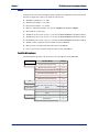
Two Wire Microphones
The following table provides a list of tested two-wire microphones for the ZFR100H.
Brand
Two-Wire Model
Voltage
Countryman
E6 (Last 2 Letter order code is S3)
3V
B6 (Last 2 Letter order code is S3)
1.5
1
5V
Isomax Instrument (Hypercardioid) M2H * W3
3
3V
Isomax Instrument (Cardioid) M2C * W3
1.5
1
5V
B3 (Last 2 Letter order code is S3)
3V
EMW (Last 2 Letter order code is S3)
1.5
1
5V
Miniture LA
LAV
AV 4063
3V
Headband 4067
Note: Other Headband requires 5 volts
3V
892*CL4
3V
898 L4
898*L4
3V
899 L4
899*L4
3V
MKE 2 Gold
MKE-2
3V
MKE-2 Platinum
3V
DPA
Audio-Technica
Sennheiser
2
ZFR100 Recording System Owner’s Manual
Chapter 1
Introduction
The ZFR100 is a fault tolerant recording system. The memory card can be ejected or the power can
be switched off while the unit is in the record mode without the possibility of any audio loss to the
point recording stops. This is unique feature of the ZFR100.
The ZFR100 records audio onto the FLASH memory card using FAT32 file system. This ensures
the FLASH memory card can be read on both Windows and Mac computers. The audio is recorded
as a single file and can only be read using the Zaxcom conversion utility. This utility is freely
available from the Zaxcom website at http://www.zaxcom.com. It allows the audio to be converted
to standard Broadcast Wave files or Zaxcom transcription format (ZTF) files.
Batteries
Two AA batteries are used in the ZFR100 and depending on the type of battery used operate from
10 to 20 hours. For the longest battery life, use Lithium or rechargeable NiMH. Any other battery
chemistry including Alkaline and “Ultra” batteries have a substantially reduced run-time compared
to Lithium or rechargeable NiMH cells.
NOTE:
Never use any battery that is missing insulation on its body. This can allow a short circuit in the
battery compartment causing damage to the transmitter.
Features
o
Broadcast quality recording
o
8 hours of audio directly on a 2 GB FLASH memory card
o
Integrated time code reader/generator
o
Broadcast WAV or MP3 recording (recording is done at 24/48)
o
8-hour loop mode or tradition record/stop mode
o
Windows and Mac software to output many formats from the FLASH memory card
o
Graphic LCD display
o
Small and lightweight
Firmware
Each ZFR100 is shipped with the latest version of the firmware. As of the writing of this manual,
this is version 5.67. Each time the recorder is powered on, the firmware revision code is displayed
for brief period in the upper right of the LCD screen.
3
Chapter 1
ZFR100 Recording System Owner’s Manual
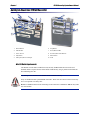
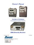
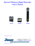
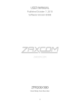
Getting to Know Your ZFR100 Recorder
2
10
3
1
4
5
8
6
9
5
1.
Record Button
6.
Stop Button
2.
Mini SD Slot
7.
Power/Record LED
3.
Power Switch
8.
Increment/Decrement Buttons
4.
Play Button
9.
Menu Button
5.
Microphone/Time Code Input
10. LCD
Mini SD Media Requirements
The ZFR100 records audio on Mini SD cards, and only SanDisk Mini SD card can be used.
SanDisk media is required because other brands of SD Memory can get jammed in the Mini SD
Slot and damage the unit.
Cau
!
tion
Cau
tion
Any damage to the unit due to non-Sandisk media voids the warranty.
Caution
4
Only use SanDisk normal speed MiniSD card media. These cards have been tested to ensure they
have an acceptable write delay time.
Do not use SanDisk Ultra II cards. Formatting an Ultra II card in a TRX900 or ZFR100 may make
the card unusable.
ZFR100 Recording System Owner’s Manual
Chapter 1
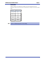
Recording Times
Media is available in sizes ranging from 128 MB to 2 GB. The following table shows the
approximate amount of time each card can record audio before recording over previously recorded
audio.
NOTE:
Media Size
Recording TIme
128 MB
30 Minutes
256 MB
1 Hour
512 MB
2 Hours
1 GB
4 Hours
2 GB
8 Hours
All times are calculated using 48 kHz / 24-bit recording.
5
Chapter 1
6
ZFR100 Recording System Owner’s Manual
ZFR100 Recording System Owner’s Manual
Chapter 2
Recording on the ZFR100
All audio from the ZFR100 is placed on the Mini SD card. This card is formatted using the ZFR100
and uses a FAT32 file system. By using the FAT32 file system, all Mini SD cards can be read by
Windows and Mac OS computers.
Audio is recorded to the memory card as a single Broadcast WAV or .ZTF (Zaxcom Transcription
Format) file. To use this audio file, you must use ZaxConvert, a transfer and conversion utility
developed by Zaxcom. ZaxConvert is available for both Windows and Mac OS and freely available
from Zaxcom’s web site at http://www.zaxcom.com. It reads and converts the audio from the Mini
SD card and places it on your computer.
Audio Quality
The high quality error free audio is always the utmost importance on the ZFR100. So when
recording, audio is always stored at 24-bit/48 kHz. The ZaxConvert utility allows you to convert
the file to 16-bits if desired, and a variety of different sample rates from the original 48þkHz.
Audio Modes
There are two recording modes on the ZFR100. There is a loop mode and a conventional mode.
Loop Mode
The loop mode provides a way to continuously record audio. Once the media card is filled, current
audio replaces the previously recorded audio at the beginning of the recording. The table on the
previous page shows the media sizes and how much recording time is available before audio is
looped. When in the loop mode, the ZFR100 displays LREC on the front status display.
Conventional Mode
The conventional mode never replaces any audio on the media card while recording. When the
Mini SD card is full the recording is automatically stopped and you must erase or change the media
card to continue recording. When in the conventional mode, the ZFR100 displays REC on the front
status display.
Memory cards from 128 MB to 2 GB can be used in the ZFR100. A 2 GB card records a single
track of audio for eight hours without erasing any recorded audio on the card.
Important:
The ZFR100 will not record to the memory card if it is not present when the unit is powered up or if
it is removed with power on. If the card is ejected with power on the card must be reinserted and the
ZFR100 power cycled in order to resume the recording function.
7
Chapter 2
ZFR100 Recording System Owner’s Manual
Menus
This section describes each of the menus in the ZFR100 and their function. To access all menus,
except the main menu, the menu button on the unit is pressed until desired menu appears.
Main Menu
The Main menu contains the following four important pieces of information.
o
Transport status - upper left corner
o
Current time code of the segment - upper left
o
Battery indication - lower left
o
Audio level - bottom of the meter
Gain Menu
Access:
Press the menu button until Gain appears in the top left of the LCD display.
The audio gain is used to set the gain of the microphone preamplifier. Use the increment and
decrement keys to set the microphone gain. The gain is adjustable over a range of 36 dB. The gain
should be set so that the meter is peaking between –20 and –10þdB. This is about half way between
–20þdB and 0þdB on the meter.
Time code menu
Access:
Press the menu button until Time Code appears in the top left of the LCD display.
When accessed, the current generator time code value appears in the menu. The current frame rate
also appears. Use the increment or decrement keys to change the current time code rate. If the rate
is set to Auto, the ZFR100 automatically sets the rate when the unit is jammed.
Lock Menu
Access:
Press the menu button until Lock appears in the top left of the LCD display.
The ZFR100 can be locked so that the Menu Key, INC and DEC keys are inoperative.
Locking the ZFR100
11. Enter the Lock menu.
12. Remain in the Lock menu for 5 seconds.
The ZFR100 automatically locks the keys.
Unlocking the ZFR100
1.
8
Press the Menu and Up Arrow keys simultaneously.
The ZFR100 unlocks the keys.
ZFR100 Recording System Owner’s Manual
Chapter 2
HIGH-PASS FILTER Menu
Access:
Press the menu button until High Pass appears in the top left of the LCD display.
The High-Pass filter menu indicates different high-pass filter cutoff frequencies. You can select a
frequency from 30þHz to 220þHz. Use the Increment and decrement keys to change the high pass
cutoff frequency.
All Filters are implemented in the digital domain, so the automatic compressor/limiter may engage
even when no substantial audio is heard. The purpose of the limiter is to prevent the mic preamp
from over-driving the A/D converter. Therefore the limiter operates on audio before it has been
processed by the high-pass filter. If there is a massive amount of low frequency audio content being
filtered out by the high pass filter, such as wind noise, you may hear the effects of the limiter
without hearing the audio that caused the limiter to engage. If this problem occurs then the gain is
set too high. Reduce the mic preamp gain below that level which triggers the limiter.
Limiter Menu
Access:
Press the menu button until Limiter appears in the top left of the LCD display.
The LCD display also displays the current status of the limiter. Use the Increment and Decrement
Keys to enable or disable the limiter.
When the input signal is too high for the gain setting, it is clipped and results in distortion and
popping. The limiter is used to prevent clipping by beginning to engage around 10 dB from
clipping. When using lavaliere microphones, you normally would enable the limiter function on the
ZFR100. However if the input signal being fed to the ZFR100 is coming from a mixer that is using
a limiter, you should not use the limiter function on the ZFR100.
Transport Buttons
The transport buttons; record, play, and stop, are located on the top of the ZFR100.
Record button
This button is used to put the ZFR100 into the record mode. If the record button is pressed when the
ZFR100 is already in record mode the ZFR100 closes the current file and open up a new file at the
time the button is pressed. The green LED blinks to confirm the creation of a new file. This is done
to mark a point in time to make it easier to identify in post-production.
Play button
Pressing the play button replays the last recording from its beginning. If the play button is pressed
when the ZFR100 is already in the play mode the playback is advanced to the next recorded
segment. The word play on the display changes to show the segment number currently being
played.
Stop Button
Pressing the stop button puts the ZFR100 into the stop mode. If the stop button is pressed when the
ZFR100 is in the stop mode the playback segment pointer is decremented to the previously
recorded segment. The word stop on the display change to show the segment number that is ready
to play.
9
Chapter 2
ZFR100 Recording System Owner’s Manual
ZFR100 Recording Operation
Card Formatting
The memory card must be formatted by the ZFR100 before recording is possible.
To format the memory card do the following.
Important:
1.
With the power off insert the memory card into the ZFR100
2.
When the unit has fully initialized, press the menu key repeatedly until the instruction appears
in the display indicating how to erase the memory card.
3.
Press the up arrow key 5 times to begin the Erasing and formatting of the memory card.
The ZFR100 displays its progress in formatting the memory card.
Ensure the ZFR100 indicates that the formatting was successful before the card is used for actual
recording. If the formatting fails do not use the memory card for recording in the ZFR100.
A 2 GB MiniSD card takes approximately 20 seconds to format.
Jamming ZFR100 Time Code
Time code is jammed into the ZFR100 by connecting it to the microphone input. When time code is
connected it takes the ZFR100 about 3 seconds to recognize the time code input. The display shows
TIME CODE when the code is recognized and the word Jammed a second later. When Jammed
disappears the time code input can be disconnected.
The audio level of the time code needs to be between 0 dB and +10 dB on the ZFR100 meter. A line
level to mic level cable should be used to attenuate the time code signal out of a generator to the
correct audio level.
The ZFR100 automatically identifies the time code rate and type. It sets itself to that rate when the
ZFR100 is jammed. Time code accuracy of the ZFR100 is about 1 frame in 5 hours.
Time code may also be jammed using the optional STA100 stereo adaptor, TCA100 time code
adaptor, or by sending time code to the TCR100 internal time code receiver from the IFB800 time
code/remote control transmitter.
Jamming time code on the ZFR100 will start a new file in the ZFR100. The file shows up in the
Zaxcom conversion utility starting at the time code location the ZFR100 was jammed at.
Important:
10
The ZFR100 will not keep time code running with power off.
ZFR100 Recording System Owner’s Manual
Chapter 2
Setting the ZFR100 Name
The name set into the ZFR100 becomes part of the file name of the audio files generated by the
ZFR100. It is also included in the metadata. 8 characters are provided for the ZFR100 name. The
ZFR100 name will appear for a few seconds on power up in the LCD display window.
Setting the ZFR100 name
1.
Press and hold the menu key as the ZFR100 is powered up.
2.
Release the menu key when the unit has fully initialized.
3.
Press the menu key repeatedly until NAME: appears in the display with an arrow pointing to
the first character.
4.
Press the up and down arrow keys to change the character that the arrow is pointing to.
The characters A-Z and 0 to 9 are the available characters.
5.
Press the menu button to proceed to the next character.
When finished press and hold the menu button to leave this function or power down the ZFR100
and the power it on to resume normal operation.
Transport Control Menu
Press the menu key on the ZFR100 until the transport status is located on the left side of the display.
The current transport time code is displayed. When in this menu it is possible to stop the ZFR100
from recording and to play back recorded material.
Pressing the Down arrow key places the ZFR100 into stop mode. While in stop mode the playback
pointer can be moved backwards by pressing the down arrow key.
Pressing the UP arrow key places the ZFR100 into play mode. While in play mode the playback
pointer can be moved forwards by pressing the up arrow key.
The current playback time code is displayed in the transport control menu.
Leaving the menu by pressing the Menu key returns the ZFR100 to the record mode at the last
location on the memory card that was recorded to.
Dual Color LED
The dual color LED on the top of the ZFR100 confirms the transport status of the recorder.
LED status indicators.
o
Solid green – ZFR100 is in stop or playback mode.
o
Green and flickers red – ZFR100 is in record mode.
o
Flashing Red – indicates there is less than 10 minutes of recording time left on the memory
card. This will never be seen in loop record mode.
o
Solid red – ZFR100 has lost communication. Check the SD card, usually it has come out of the
SD slot, it is full, or has not been formatted correctly.
11
Chapter 2
12
ZFR100 Recording System Owner’s Manual
ZFR100 Recording System Owner’s Manual
Chapter 3
ZaxConvert
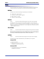
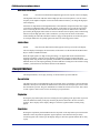
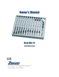
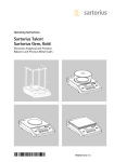
About ZaxConvert
The ZaxConvert software is available for both Microsoft Windows and Mac OS X. The software is
functionally identical on both operating systems. You must use the ZaxConvert software to convert
the audio from .ZAX files to .WAV files.
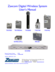
Windows XP – Main Window
Mac OS X – Main Window
Using ZaxConvert
When you use ZaxConvert, you must first assign an output folder. Next, add your source folder.
The following buttons contain additional options that are available when translating ZAX files to
broadcast WAV files:
o
Output File Type
o
Time Code
o
Sample Rate Conversion
o
Maximum File Size
o
Output File Name
o
Track Enable
When displayed on the main screen, the button shows the current setting.
13
Chapter 3
ZFR100 Recording System Owner’s Manual
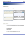
Output File Type
This menu allows you to select the number of channels, bit depth, and output file type. In addition,
if the Post Production facility is using a DV40, you can force a 48K stamp to be used on the output
files.
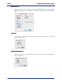
Time Code
This menu allows you to pull up or pull down time code, or leave the time code as it was set during
the recording of the audio.
Sample Rate Conversion
This menu allows you to convert the sample rate from the 48 kHz sample rate used by the ZFR100
when recording audio.
14
ZFR100 Recording System Owner’s Manual
Chapter 3
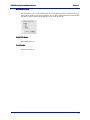
Maximum File Size
This menu allows you to set the maximum file size of the audio tracks. This is useful when trying to
place audio on media or when trying to limit the file size. Many audio applications can only handle
files that are 2 GB or smaller due to limitations in the .WAV file format.
Output File Name
Reserved for future use.
Track Enable
Reserved for future use.
15
Chapter 3
16
ZFR100 Recording System Owner’s Manual
ZFR100 Recording System Owner’s Manual
Chapter 4
Specifications
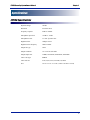
ZFR100 Specifcations
Dynamic Range
106 dB
Distortion
Less than .001%
Frequency response
20 Hz to 20 KHz
Microphone input level
-60 dB to –24 dB
Microphone Power
3.3 VDC @10 mA max
High Pass filter
18dB per octave
High Pass Filter frequency
30Hz to 220Hz
Output file type
.WAV
Output resolution
16- or 24- bits selectable
Output sample rate
32 KHz, 44100 KHz, 48000 KHz, 48048 KHz
Time Code Type
SMPTE
Time code rate
23.96, 24,25, 29.97, 29.97DF, 30, 30DF
Size
3.0-in. x 2.3-in. x 0.75-in. (76 mm x 58 mm x 19 mm)
17
Chapter 4
18
ZFR100 Recording System Owner’s Manual
ZFR100 Recording System Owner’s Manual
Chapter 5
Cables
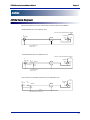
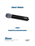
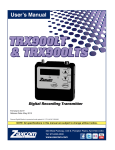
ZFR100 Cable Diagrams
This section contains a list of all connections to construct cables for the ZFR100.
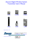
XLR Female Balanced to 3 Pin LEMO Mic Level
View from outside the TRX900/900AA & ZFR100
Gnd
J2
XLR Female
1
3 Pin LEMO
3
+3.3V
2
2
Audio
1
3
Use a shielded cable
Length - 2 feet
XLR Female Balanced to 3 Pin LEMO Line Level
View from outside the TRX900/900AA & ZFR100
Gnd
J2
XLR Female
1
2
3
R2
10.0 K
3 Pin LEMO
+3.3V
2
40 dB Pad
Parts in XLR
3
Audio
1
R1
100
Use a shielded cable
Length - 2 Feet
RCA Consumer Line Level Male Unbalanced to 3 Pin LEMO Mic Level
Gnd
J4
RCA jack
1
2
R2
4.7K
Parts in RCA jack
3 Pin LEMO
3
+3.3V
2
34dB Pad
Audio
1
R1
100
Shield
Cable diameter approximately .100"
19
Chapter 5
20
ZFR100 Recording System Owner’s Manual
ZFR100 Recording System Owner’s Manual
Addendum
STA100 - Addendum
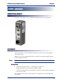
STA100 Stereo Adaptor
The STA100 stereo adaptor converts a TRX900 and ZFR100 recorder to stereo operation.
Installation
The STA100 attaches to either the TRX900 or ZFR100 unit with two screws located under the
"Stereo adaptor" label.
Tighten the two screws, alternating between the two, until the stereo adaptor and the transmitter/
recorder are tightly connected.
Caution:
Do not to over tighten the screws.
Setting Levels
1.
Connect the TA5 male connector to a suitable line level audio source.
The line level needs to be at a level between -6dBu to +8dBu.
2.
Output tone from the field mixer and adjust the two input pots so the meter on the LCD display
is at a level of -20 dB.
The stereo adaptor does not have a limiter function so it is important not to clip the input of the
stereo adaptor.
21
Addendum
ZFR100 Recording System Owner’s Manual
Power connector
Using external power to the STA100 is optional. When 12 VDC is not supplied to the unit, it
operates using the internal battery of either the ZFR100 or TRX900.
If the 12-volt input is connected to a power source, it powers the ZFR100 or TRX900 when they
are turned off.
If batteries are installed in the ZFR100 or TRX900 and external power is connected, the unit will
not be able to shut off unless an external power switch is available to remove the external power
connection.
Audio Output Connector
The audio output connection has multiple uses. It is used to monitor the audio functions of its host
unit. The audio or time code output depends on the operation mode of the host unit.
Time Code Input Connector
The time code input is used to jam the time code generator of the host unit. If the host unit has an
auto-load function the time code input of the stereo adaptor can be used.
Operation
For the stereo adaptor to operate the host unit must select the stereo mode of operation. and the unit
must have external ADC selected. For details on enabling ADC, see the manual of the host unit.
Selecting the stereo mode sets the host unit to its stereo mode of operation. The ADC selection
selects the internal mic input if selected to internal or the stereo adaptor audio if selected to external
mode.
Hint:
22
The Stereo adaptor can be used to power the host unit while the host is in mono mode and its mic
level input is in use.
Zaxcom Warranty Policy and Limitations
ZFR100 Recording System Owner’s Manual
Warranty
Zaxcom Warranty Policy and Limitations
Zaxcom Inc. values your business and always attempts to provide you with the very best service.
No limited warranty is provided by Zaxcom unless your Zaxcom ZFR100 (“Product”) was purchased from an authorized distributor or authorized reseller. Distributors may sell Products to
resellers who then sell Products to end users. Please see below for warranty information or obtaining service. No warranty service is provided unless the Product is returned to Zaxcom Inc. or a Zaxcom dealer in the region where the Product was first shipped by Zaxcom.
Warranty Policy
Zaxcom ZFR100 carries a Standard Warranty Period of one (1) year.
NOTE:
The warranty period commences from the date of delivery from the Zaxcom dealer or reseller
to the end user.
There are no warranties which extend beyond the face of the Zaxcom limited warranty. Zaxcom
disclaims all other warranties, express or implied, regarding the Products, including any implied
warranties of merchantability, fitness for a particular purpose or non-infringement. In the United
States, some laws do not allow the exclusion of the implied warranties.
Return Material Authorization (RMA)
No Product may be returned directly to Zaxcom without first contacting Zaxcom for a Return Material Authorization ("RMA") number. If it is determined that the ZFR100 may be defective, you will
be given an RMA number and instructions for Product return. An unauthorized return, i.e. one for
which an RMA number has not been issued, will be returned to you at your expense. Authorized
returns are to be shipped prepaid and insured to the address on the RMA in an approved shipping
container. Your original box and packaging materials should be kept for storing or shipping your
Product. To request an RMA, please contact Zaxcom by telephone. There is an RMA form on the
Zaxcom web site www.zaxcom.com. Please fill out the form and return it with the product for
repair. Zaxcom will return the warranty repair via 2nd day UPS or FedEx at their discretion. If overnight service is required a FedEx or UPS account number must be provided to Zaxcom to cover the
shipping expenses.
Warranty Limitations
Zaxcom's limited warranty provides that, subject to the following limitations, each Product will be
free from defects in material and workmanship and will conform to Zaxcom's specification for the
particular Product.
23
ZFR100 Recording System Owner’s Manual
Zaxcom Warranty Policy and Limitations
Limitation of Remedies
Your exclusive remedy for any defective Product is limited to the repair or replacement of the
defective Product.
Zaxcom may elect which remedy or combination of remedies to provide in its sole discretion. Zaxcom shall have a reasonable time after determining that a defective Product exists to repair or
replace a defective Product. Zaxcom's replacement Product under its limited warranty will be manufactured from new and serviceable used parts. Zaxcom's warranty applies to repaired or replaced
Products for the balance of the applicable period of the original warranty or thirty days from the
date of shipment of a repaired or replaced Product, whichever is longer.
Limitation of Damages
Zaxcom's entire liability for any defective Product shall in no event exceed the purchase price for
the defective Product. This limitation applies even if Zaxcom cannot or does not repair or replace
any defective Product and your exclusive remedy fails of its essential purpose.
No Consequential or Other Damages
Zaxcom has no liability for general, consequential, incidental or special damages. These include
loss of recorded data, the cost of recovery of lost data, lost profits and the cost of the installation or
removal of any Products, the installation of replacement Products, and any inspection, testing, or
redesign caused by any defect or by the repair or replacement of Products arising from a defect in
any Product.
In the United States, some states do not allow exclusion or limitation of incidental or consequential
damages, so the limitations above may not apply to you. This warranty gives you specific legal
rights, and you may also have other rights which vary from state to state.
Your Use of the Product
Zaxcom will have no liability for any Product returned if Zaxcom determines that:
q
The product was stolen from Zaxcom
q
The asserted defect:
1.
is not present,
2.
cannot reasonably be fixed because of damage occurring when the Product is in the possession
of someone other than Zaxcom, or
3.
is attributable to misuse, improper installation, alteration (including removing or obliterating
labels and opening or removing external covers (unless authorized to do so by Zaxcom or an
authorized Service Center)), accident or mishandling while in the possession of someone other
than Zaxcom.
q
The Product was not sold to you as new.
Additional Limitations on Warranty
Zaxcom's warranty does not cover Products which have been received improperly packaged,
altered, or physically abused.
24