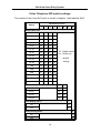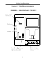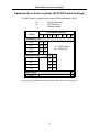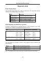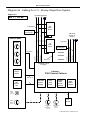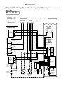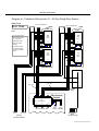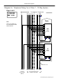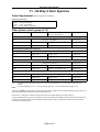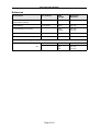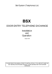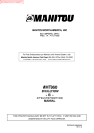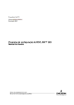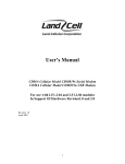
1
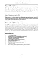
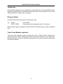
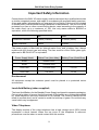
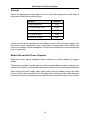
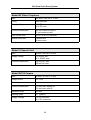
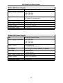
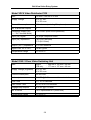
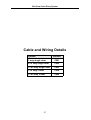
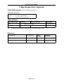
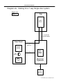
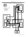
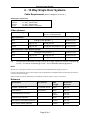
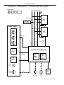
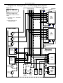
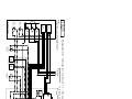
Bell System (Telephones) Ltd.
bellview
Video Entry System
Installation & Operation
Manual
PD-007 Issue 3
TABLE OF CONTENTS
General Description . . . . . . . . . . . . . . . . . . . . . . . . . . . . . . . . . . . . . . . . . . . . . . . . 1
Video Telephones (model BV) . . . . . . . . . . . . . . . . . . . . . . . . . . . . . . . . . . . . . . . . . . . . . . . . 1
Entrance Panel (BVP series) . . . . . . . . . . . . . . . . . . . . . . . . . . . . . . . . . . . . . . . . . . . . . . . . . 1
System Features . . . . . . . . . . . . . . . . . . . . . . . . . . . . . . . . . . . . . . . . . . . . . . . . . . . . . . . . . . . 1
System Operation . . . . . . . . . . . . . . . . . . . . . . . . . . . . . . . . . . . . . . . . . . . . . . . . . . 3
General . . . . . . . . . . . . . . . . . . . . . . . . . . . . . . . . . . . . . . . . . . . . . . . . . . . . . . . . . . . . . . . . . .
Privacy mode (buzzer mute) . . . . . . . . . . . . . . . . . . . . . . . . . . . . . . . . . . . . . . . . . . . . . . . . . .
Multi-door operation . . . . . . . . . . . . . . . . . . . . . . . . . . . . . . . . . . . . . . . . . . . . . . . . . . . . . . . .
Monitor Mode . . . . . . . . . . . . . . . . . . . . . . . . . . . . . . . . . . . . . . . . . . . . . . . . . . . . . . . . . . . . .
3
3
3
3
Equipment Required . . . . . . . . . . . . . . . . . . . . . . . . . . . . . . . . . . . . . . . . . . . . . . . 4
Control Cabinet / Power Supply . . . . . . . . . . . . . . . . . . . . . . . . . . . . . . . . . . . . . . . . . . . . . . .
Cabinet Components . . . . . . . . . . . . . . . . . . . . . . . . . . . . . . . . . . . . . . . . . . . . . . . . . . . . . . .
Telephones . . . . . . . . . . . . . . . . . . . . . . . . . . . . . . . . . . . . . . . . . . . . . . . . . . . . . . . . . . . . . . .
Entrance Panel . . . . . . . . . . . . . . . . . . . . . . . . . . . . . . . . . . . . . . . . . . . . . . . . . . . . . . . . . . . .
Time Clock Module (optional) . . . . . . . . . . . . . . . . . . . . . . . . . . . . . . . . . . . . . . . . . . . . . . . . .
4
4
5
5
5
System Design Considerations . . . . . . . . . . . . . . . . . . . . . . . . . . . . . . . . . . . . . . . 6
Cable requirements . . . . . . . . . . . . . . . . . . . . . . . . . . . . . . . . . . . . . . . . . . . . . . . . . . . . . . . .
Multiple video telephones in one flat . . . . . . . . . . . . . . . . . . . . . . . . . . . . . . . . . . . . . . . . . . .
Multi-way systems . . . . . . . . . . . . . . . . . . . . . . . . . . . . . . . . . . . . . . . . . . . . . . . . . . . . . . . . . .
Electric Door Release . . . . . . . . . . . . . . . . . . . . . . . . . . . . . . . . . . . . . . . . . . . . . . . . . . . . . . .
Trades Button (optional) . . . . . . . . . . . . . . . . . . . . . . . . . . . . . . . . . . . . . . . . . . . . . . . . . . . . .
Exit Button (optional) . . . . . . . . . . . . . . . . . . . . . . . . . . . . . . . . . . . . . . . . . . . . . . . . . . . . . . .
Fire Switch (optional) . . . . . . . . . . . . . . . . . . . . . . . . . . . . . . . . . . . . . . . . . . . . . . . . . . . . . . .
Door Monitor Switch (optional) . . . . . . . . . . . . . . . . . . . . . . . . . . . . . . . . . . . . . . . . . . . . . . . .
6
6
6
7
7
7
7
7
Installation . . . . . . . . . . . . . . . . . . . . . . . . . . . . . . . . . . . . . . . . . . . . . . . . . . . . . . . . 8
Important Safety Information . . . . . . . . . . . . . . . . . . . . . . . . . . . . . . . . . . . . . . . . . . . . . . . . . 9
General . . . . . . . . . . . . . . . . . . . . . . . . . . . . . . . . . . . . . . . . . . . . . . . . . . . . . . . . . . . . . . . . . 10
Model 440 and 540 Power Supplies . . . . . . . . . . . . . . . . . . . . . . . . . . . . . . . . . . . . . . . . . . . 10
PSU138A, PSU138B Power Supplies . . . . . . . . . . . . . . . . . . . . . . . . . . . . . . . . . . . . . . . . . 11
Entrance Panel . . . . . . . . . . . . . . . . . . . . . . . . . . . . . . . . . . . . . . . . . . . . . . . . . . . . . . . . . . . 11
Electric Door Release . . . . . . . . . . . . . . . . . . . . . . . . . . . . . . . . . . . . . . . . . . . . . . . . . . . . . . 11
Video Telephones . . . . . . . . . . . . . . . . . . . . . . . . . . . . . . . . . . . . . . . . . . . . . . . . . . . . . . . . . 12
Commissioning . . . . . . . . . . . . . . . . . . . . . . . . . . . . . . . . . . . . . . . . . . . . . . . . . . . 13
Video Telephone settings . . . . . . . . . . . . . . . . . . . . . . . . . . . . . . . . . . . . . . . . . . . . . . . . . . .
Picture Adjustment . . . . . . . . . . . . . . . . . . . . . . . . . . . . . . . . . . . . . . . . . . . . . . . . . .
Buzzer mute time . . . . . . . . . . . . . . . . . . . . . . . . . . . . . . . . . . . . . . . . . . . . . . . . . . .
Call Active time . . . . . . . . . . . . . . . . . . . . . . . . . . . . . . . . . . . . . . . . . . . . . . . . . . . .
Auto - Display option . . . . . . . . . . . . . . . . . . . . . . . . . . . . . . . . . . . . . . . . . . . . . . . .
Video Privacy option . . . . . . . . . . . . . . . . . . . . . . . . . . . . . . . . . . . . . . . . . . . . . . . .
Disabling the CAMERA and VIEW buttons . . . . . . . . . . . . . . . . . . . . . . . . . . . . . . .
DIP switch settings . . . . . . . . . . . . . . . . . . . . . . . . . . . . . . . . . . . . . . . . . . . . . . . . . .
Diagram 1 : Video Phone Adjustments . . . . . . . . . . . . . . . . . . . . . . . . . . . . . . . . . . . . . . . .
Lock Release Adjustment . . . . . . . . . . . . . . . . . . . . . . . . . . . . . . . . . . . . . . . . . . . . . . . . . . .
540 Power Supply . . . . . . . . . . . . . . . . . . . . . . . . . . . . . . . . . . . . . . . . . . . . . . . . . .
LT88 Lock Timer PCB (supplied in a cabinet) . . . . . . . . . . . . . . . . . . . . . . . . . . . .
Adjustments on 2 door systems ( 819S Switching Unit) . . . . . . . . . . . . . . . . . . . . . . . . . . .
Lock Release Time . . . . . . . . . . . . . . . . . . . . . . . . . . . . . . . . . . . . . . . . . . . . . . . . .
Call / Active Time . . . . . . . . . . . . . . . . . . . . . . . . . . . . . . . . . . . . . . . . . . . . . . . . . . .
Speech Adjustments . . . . . . . . . . . . . . . . . . . . . . . . . . . . . . . . . . . . . . . . . . . . . . . . . . . . . . .
819S DIP Switch Settings . . . . . . . . . . . . . . . . . . . . . . . . . . . . . . . . . . . . . . . . . . . . . . . . . . .
13
13
13
13
13
13
13
14
15
16
16
16
16
16
16
16
17
Troubleshooting . . . . . . . . . . . . . . . . . . . . . . . . . . . . . . . . . . . . . . . . . . . . . . . . . . 18
Diagnostic Aids . . . . . . . . . . . . . . . . . . . . . . . . . . . . . . . . . . . . . . . . . . . . . . . . . . . . . . . . . . .
Power Supply Status . . . . . . . . . . . . . . . . . . . . . . . . . . . . . . . . . . . . . . . . . . . . . . . .
819S Switching unit (Multi-door systems) . . . . . . . . . . . . . . . . . . . . . . . . . . . . . . . .
Fault Finding . . . . . . . . . . . . . . . . . . . . . . . . . . . . . . . . . . . . . . . . . . . . . . . . . . . . . . . . . . . . .
19
19
19
20
Specifications . . . . . . . . . . . . . . . . . . . . . . . . . . . . . . . . . . . . . . . . . . . . . . . . . . . . 23
Model BV Video Telephone . . . . . . . . . . . . . . . . . . . . . . . . . . . . . . . . . . . . . . . . . . . . . . . . .
Model 61 Speech Unit . . . . . . . . . . . . . . . . . . . . . . . . . . . . . . . . . . . . . . . . . . . . . . . . . . . . .
Model BV700 Camera . . . . . . . . . . . . . . . . . . . . . . . . . . . . . . . . . . . . . . . . . . . . . . . . . . . . .
Model 440 Power Supply . . . . . . . . . . . . . . . . . . . . . . . . . . . . . . . . . . . . . . . . . . . . . . . . . . .
Model 540 Power Supply . . . . . . . . . . . . . . . . . . . . . . . . . . . . . . . . . . . . . . . . . . . . . . . . . . .
Model VDC6 Video Distributor PCB . . . . . . . . . . . . . . . . . . . . . . . . . . . . . . . . . . . . . . . . . . .
Model 819S 2 Door Video Switching Unit . . . . . . . . . . . . . . . . . . . . . . . . . . . . . . . . . . . . . .
24
24
24
25
25
26
26
Cable and Wiring Details . . . . . . . . . . . . . . . . . . . . . . . . . . . . . . . . . . . . . . . . . . . 27
1 way single door . . . . . . . . . . . . . . . . . . . . . . . . . . . . . . . . . . . . . . . . . . . . . . . . . . . . . . .
2-10 way single door . . . . . . . . . . . . . . . . . . . . . . . . . . . . . . . . . . . . . . . . . . . . . . . . . . . . .
11-60 way single door . . . . . . . . . . . . . . . . . . . . . . . . . . . . . . . . . . . . . . . . . . . . . . . . . . . .
1-10 way 2 door . . . . . . . . . . . . . . . . . . . . . . . . . . . . . . . . . . . . . . . . . . . . . . . . . . . . . . . .
11-60 way 2 door . . . . . . . . . . . . . . . . . . . . . . . . . . . . . . . . . . . . . . . . . . . . . . . . . . . . . . .
CW1
CW2
CW3
CW4
CW5
Bell View Video Entry System
General Description
The bellview Video Door Entry Telephone System is a high quality, versatile security
product for controlling access to private houses, residential homes, blocks of flats and
offices. The occupants are supplied with individual video entry telephones which enable
them to view the person calling at the entrance; to converse with the caller; and if
desired allow them access to the building via an electric lock release.
Video Telephones (model BV)
This is a slimline, wall-mounting unit, manufactured in high quality impact resistant ABS
plastic. It has a 4" flat tube display with variable contrast and brightness, providing a
high definition, high quality picture. Up to 10 telephones may be directly connected on
to the system without the need for a video distributor.
Entrance Panel (BVP series)
The BVP series of aluminium panels are available in most sizes (depending on the
number of push buttons required), and are supplied with a flush-fitting back box.
Stainless steel or brass Vandal Resistant panels are also available to order, engraved
with the customers particular requirements. Each panel includes a high quality two-way
speech amplifier (model 61) concealed behind a grill, and a solid-state CCD camera
(model BV700) which is protected by a high impact strength lexan window. The camera
includes four, high intensity infrared lamps for illumination of the caller at night time.
System Features
!
!
!
!
!
!
!
!
!
!
!
4" Flat screen monitor
High resolution CCD camera with infrared lamps
High quality, full-duplex speech amplifier
Tradesman facility (optional)
Facility for egress button and/or fire switch
Privacy function (buzzer mute)
Full privacy of speech
Door Status indication
Outputs for fail safe and fail secure locks
Lock release timer
Mains / battery status indication (battery backup models)
1
Bell View Video Entry System
Telephone Controls
Brightness
Contrast
Door Open LED
Mute LED
DOOR
VIEW
CAMERA
Unlocks the door
PORTER
PRIVATE
Camera Select
Monitor entrance
2
Buzzer mute
Bell View Video Entry System
System Operation
General
The entrance panel, which includes the camera and speech unit, should be located on
a wall adjacent to the building entrance. A visitor can contact any resident by pressing
the appropriate button on the entrance panel which will call the resident's video
telephone (sounds a buzzer), activating the display and enabling speech. The resident
can view the caller on the video screen and by picking up the handset freely converse
with the visitor. The telephone will remain active for a fixed period (adjustable 30-120
seconds).
If the resident wishes the caller to gain access to the building, the DOOR button can be
pushed while the video telephone is still active; this will operate an electric lock release
on the entrance door for a short period (adjustable, typically 5 seconds).
Privacy mode (buzzer mute)
To avoid disturbance from nuisance calls the resident may push the PRIVATE button
on the video telephone. This will mute the buzzer for a fixed period (adjustable between
1 minute and 10 hours) and illuminate a red indicator lamp. Pushing the button again
will re-enable the buzzer and extinguish the lamp.
Multi-door operation
When a call is made from an entrance panel it will automatically switch operation to
that door. The camera and speech unit of the active panel will remain live for a fixed
period (adjustable 30-120 seconds) during which time the other entrances are locked
out. An optional engaged lamp may be fitted at each entrance as an indication that
another door is in use.
The resident may change the view between doors by pressing the CAMERA button.
Monitor Mode
On a single way system a resident may view the entrance at any time by pressing the
telephone VIEW button (This feature may be disabled if required).
Privacy
The bellview system offers full privacy of speech, that is, only the resident who has
been called may listen and speak with the caller. On multi-way systems the CAMERA
and VIEW buttons can be made private to prevent other residents monitoring visitors.
To enhance system security and reliability a lock privacy function is provided, which
ensures only the resident who has been called can unlock an entrance.
3
Bell View Video Entry System
Equipment Required
Control Cabinet / Power Supply
For systems exceeding 10 ways or requiring battery backup, an IP55-rated, lockable
steel cabinet is supplied, containing the power supply and control circuitry. This is
available for smaller systems on request.
System
Control Cabinet /Power Supply model
1-10 Way
1 Door
Model 540 Power Supply
11-60 Way
1 Door
CABV/60/1:
1-10 Way
2 Door
Model 440 Power Supply
Model 819S Door Switching Unit
11-60 Way
2 Door
CABV/60/2:
PSU138B
LT88
VDC6
PSU138B
819S
VDC6
Power Supply
Lock Timer
Video Distributor
Power Supply
Door Switching Unit
Video Distributor
With Battery Backup PSU (requires 12V 6AH sealed Lead-Acid battery)
1-10 Way
1 Door
CABV/10/1:
PSU138A
LT88
Power Supply
Lock Timer
1-10 Way
2 Door
CABV/10/2:
PSU138A
819S
Power Supply
Door Switching Unit
Cabinet Components
440
-
12VDC, 1.5A Power Supply.
540
-
12VDC, 1.5A Power Supply, with integral lock timer (3 - 27 secs).
It can connect directly to a Fail safe or Fail secure lock release.
PSU138A
-
12V 1A Power Supply with Battery Backup Facility
PSU138B
-
12V 4.5A Power Supply with Battery Backup Facility
LT88
-
Lock Timer (adjustable 3 - 25 second). It can connect directly to a
Fail safe or Fail secure lock release.
VDC6
-
Video Distributor with 6 outputs and distribution to up to 60
telephones (10 on each output).
819S
-
Two-Door Switching Unit, including Lock Timers (3-20 secs).
4
Bell View Video Entry System
Telephones
One model BV video door entry telephone is required per flat. The model 500PX series
telephones (depending on the features required) may be used in place of one or more
video telephones, if audio only is required.
Entrance Panel
One BVP series entrance panel is required per door.
e.g.
BVP5
BVP10-TRBV
5 way Panel
10 way panel with tradesman facility (11 buttons)
Each entrance panel contains a model BV700 CCD Camera and a model 61 Speech
Unit.
Time Clock Module (optional)
The Time clock module is used in conjunction with a Trades button. Systems are
supplied with the model TS2000, which can be used as a 24 hour or 7 day Time clock.
On systems above 10 way or with battery backup, the Time clock will be pre-fitted inside
the Control Cabinet.
5
Bell View Video Entry System
System Design Considerations
Cable requirements
Refer to one of the following sections according to your system requirements:
System
Section
1 way single door
CW1
2-10 way single door
CW2
11-60 way single door
CW3
1-10 way 2 door
CW4
11-60 way 2 door
CW5
Multiple video telephones in one flat
When several video telephones are installed in a single flat, it is usually necessary to
disable the auto-display feature on all telephones (see page 13), to prevent the power
supply and cable voltage drops being exceeded. In this case the resident must press
the VIEW button in order to view the caller.
Multi-way systems
The VIEW function is provided primarily for single-way systems. On multi-way systems,
it is highly advisable to set the video telephone to ‘Video Privacy’ (see page 13) to
prevent other residents from monitoring visitors and to ensure that the maximum no. of
active monitors is not exceeded.
Should the VIEW function be required please contact the distributor or manufacturer for
further guidance
6
Bell View Video Entry System
Electric Door Release
Fail-Secure releases are the most commonly used devices, they require power to
release the lock and will secure the door upon power failure. Fail-Safe lock releases
and magnetic locks require continuous power to hold the lock and will release the door
upon power failure. All of these types can be accommodated providing they are rated
at 12V DC with a maximum current consumption of 0.5A. For lock releases that have
different requirements contact your distributor for further guidance.
Trades Button (optional)
The entrance panels may be ordered with an optional Trades button to allow free
access during certain hours (used in conjunction with a time clock). Momentarily
pressing the button will operate the lock release for a fixed period (adjustable, typically
5 seconds).
Exit Button (optional)
Typically this facility is used to allow personnel to freely exit through the controlled
entrance. Momentarily operating the push-button will directly operate the lock release
for a fixed period (adjustable, typically 5 seconds).
Fire Switch (optional)
The fire switch is usually a key or lever switch which can be operated by the fire-brigade
to gain access to the building. To use this feature the Lock release(s) must be
continuously rated.
Door Monitor Switch (optional)
Each Telephone has a green LED indicator above the DOOR button to show when the
door is open. This is detected by the closure of a door monitor switch. The switch
should be rated at 1A ( for up to 60 phones). Lock Releases are available with an
integral Door Monitoring switch.
7
Bell View Video Entry System
Installation
8
Bell View Video Entry System
Important Safety Information
Connections to the 240V AC mains supply must be carried out by a qualified electrician
or similar competent person, and made in accordance with accepted safety practices.
A two-pole switch (as provided by a Consumer Unit or Switch-Fuse) must be included
to isolate both Live and Neutral during Installation or Maintenance. The circuit must be
protected by a fuse or other current-limiting device, rated according to the capacity of
the cable used, up to a maximum of 10A. Use only mains cable to BS6004 or
equivalent, within the following specified limits:
Min
Max
Conductor Diameter
1.0mm (0.8mm2)
2.25mm (4mm2)
Cable Diameter
4.0mm
8.0mm
The power supply is fitted with an internal mains fuse, and a battery fuse; always
replace with the correct type and rating. The fuse must be of the 20mm glass type,
approved to BS EN 60127 or equivalent:
Power Supply Model
Mains Fuse (time delay)
Battery Fuse (Quick Blow)
M440
T250mA 250V
M540
T250mA 250V
PSU138A
T315mA 250V
F3.15A
PSU138B
T1A 250V
F6.3A
Environment
All equipment except the entrance panel must be placed in a protected indoor
environment.
Lead-Acid Battery (when supplied)
The Lead-Acid Battery for the Standby Power Supply is shipped in separate packaging.
Care must be taken to ensure that the terminals of the battery are not shorted together
by metal objects as this may constitute a Fire Hazard. The Control Cabinet is IP55
rated (to exclude dust) and is vented to avoid the build-up of gases. Do not block any
vents which may be apparent.
Video Telephone
The display module of the video telephone has a high voltage circuit (2KV) which
represents a shock hazard. When the top cover of the telephone is removed,
precautions must be taken to avoid contact with this module.
9
Bell View Video Entry System
General
Select the appropriate wiring diagram from one of the following sections, and install in
accordance with the instructions given:
System
Section
1 way single door
CW1
2-10 way single door
CW2
11-60 way single door
CW3
1-10 way 2 door
CW4
11-60 way 2 door
CW5
Initially connect all the equipment to one telephone only. With the power applied, test
the system is fully operational. Only if everything is functioning correctly should you
continue to connect further telephones. Connect one telephone at a time testing after
each is connected.
Model 440 and 540 Power Supplies
Read the section called ‘Important Safety Information’ before installing the power
supply.
These power supplies must be wall-mounted onto plasterboard, wood or a similar nonconductive material, in a protected indoor environment such as an electrical cupboard.
When fitting the power supply cable (both mains and low voltage) ensure the cable
entry cut-outs in the enclosure lid are no larger than necessary for the cable diameter
used and under no circumstances must they be taken beyond the outer cut-out zones.
10
Bell View Video Entry System
PSU138A, PSU138B Power Supplies
Read the section called ‘Important Safety Information’ before installing the power
supply.
A good mains safety earth must be connected to the cabinet housing the power supply.
The cabinet must be placed in a protected indoor environment and not exposed to
dripping or splashing. The Cabinet must be secured to the wall with adequate fixings
so that there is no possibility of it falling down.
The Lead Acid battery should only be connected once the system has been fully tested.
Connection is made by 2 leads with spade terminals from the power supply. Observe
the correct polarity (red to positive, black to negative).
The PSU Control Cabinet contains a small PCB labelled ‘Power Supply Distributor’ .
This is used to supply 12V to external components. Do not cut or modify the power
supply leads as supplied.
Entrance Panel
Careful consideration should be given to the location of the entrance panel to ensure
the best possible lighting conditions for the camera. In general strong back-lighting of
the subject (by the sun and sky) should be avoided as the contrast between foreground
and background may be too great for the camera. The field of view should contain as
little of the sky as possible, particularly if south facing - a wall or other buildings would
be preferable. If a back-lit situation is unavoidable, additional lighting may be necessary
to illuminate the caller and avoid a dark outline image.
The panel should be mounted at an optimum height of 1.6 m, measured between the
ground and camera window.
Electric Door Release
Use the FAIL-SECR connections for fail-secure releases; use the FAIL-SAFE
connections for fail-safe releases and magnetic locks. When installing lock releases
please allow a little movement on the door as operation will be impaired if fitted too
tight.
11
Bell View Video Entry System
Video Telephones (Refer to diagram 1)
Also refer to the ‘Commissioning’ section for further information.
IMPORTANT:
The video telephone has a slide switch which terminates the coax cable with a 75S
impedance. When more than one video telephone is installed, all video telephones
must be set to HI (ie no termination) except the last telephone on each cable branch
which should be set to 75R.
12
Bell View Video Entry System
Commissioning
Video Telephone settings
Picture Adjustment
To adjust the BRIGHTNESS and CONTRAST of the picture adjust the two thumbwheel controls at the left hand side of the telephone.
Buzzer mute time
This is he time for which the telephone buzzer will be switched off when the buzzer
mute button is pressed. Set between 1 minute and 10 hours (see SW2 settings,
overleaf).
Call Active time
The telephone active time is the duration for which the telephone remains active
(display and speech) when called. Set between 30 and 120 seconds (see SW2 settings
overleaf).
Auto - Display option
The ‘Auto-display’ option allows the display and speech to activate when the telephone
is called; when deselected the telephone will buzz, but display and speech will not
activate until a CAMERA or VIEW button is pressed. (See SW2 settings overleaf). It
may be desirable to disable this function on multi-way systems (refer to Design
Considerations)
Video Privacy option
Enabling this option will disable the CAMERA and VIEW buttons, except for the
telephone which has been called (See SW2 settings below).It is advisable to disable
this functions on multi-way systems (refer to Design Considerations)
Disabling the CAMERA and VIEW buttons
The CAMERA and VIEW buttons can be enabled/disabled by using the slide switch on
the telephone PCB (BV/2).
13
Bell View Video Entry System
Video Telephone DIP switch settings
The location of the 8 way DIP switch is shown in diagram 1 and labelled ‘SW2'.
DIP Switch Position
Setting
1
2
3
4
1 min
off
off
off
off
2 min
off
off
off
on
3 min
off
off
on
off
5 min
off
off
on
on
8 min
off
on
off
off
10 min
off
on
off
on
15 min
off
on
on
off
20 min
off
on
on
on
30 min
on
off
off
off
45 min
on
off
off
on
1HR
on
off
on
off
2HR
on
off
on
on
3HR
on
on
off
off
5HR
on
on
off
on
8HR
on
on
on
off
10HR
on
on
on
on
5
6
7
8
Buzzer Mute Time
*
setting
6
30 sec
off
off
60 sec
off
on
90 sec
on
off
120 sec
on
on
7
Auto-Display option
*
* - default
5
Call / Active Time
*
off - Switch down
on - Switch up
No
off
Yes
on
Video Privacy option
8
*
No
off
Yes
on
14
Bell View Video Entry System
Diagram 1 : Video Phone Adjustments
WARNING : HIGH VOLTAGES PRESENT
Settings/Options
DIP-Switch
ON
Brightness
75R
I
R
O
T
Z
V
HI
Contrast
12345678
L
CAM
PORT
12V +
-
M
S
S
M
NO
YES
VIEW/CAM
Sets Co-ax Terminating
impedence 75R or
high impedence (HI)
15
Enables/disables
Camera and View
buttons
Bell View Video Entry System
Lock Release Adjustment
540 Power Supply
Adjust the preset VR1 to the required time, turning clockwise to increase the time.
Shorting ‘Z’ to ‘12V -’ will operate the internal lock relay, for the preset time (and an
audible click heard).
LT88 Lock Timer PCB (supplied in a cabinet)
Adjust the preset VR1 to the required time, turning clockwise to increase the time.
Shorting the TRIG terminals together will operate the LT88 lock relay, for the preset
time (and an audible click heard).
Adjustments on 2 door systems ( 819S Switching Unit)
Refer to DIP switch settings in the table overleaf.
Lock Release Time
The time the lock release operates for when a telephone lock button, exit button, fire
switch or trades facility is used. The time can be set between 3 and 20 seconds
according to the DIP switch setting.
Call / Active Time
The time the entrance remains active (display and speech) when a call is made. The
time must be set to the same as the telephones’. Set between 30 and 120 seconds
according to the DIP switch setting.
Speech Adjustments
Make sure the Speech Unit is fitted tight against the front grill to avoid possible
feedback effects. The speech volume may be adjusted by carefully applying a small
screwdriver to the back of the Speech Unit; 'A' (speaker symbol) adjusts the speech
level at the panel and 'B' (microphone symbol) adjusts the speech level at the
telephone.
16
Bell View Video Entry System
Adjustments on 2 door systems (819S DIP Switch Settings)
The DIP switch is located on the lower PCB and marked ‘SW2'.
off
on
*
-
DIP Switch down
DIP Switch up
Default setting
DIP Switch Position
Setting
1
2
3
4
5
6
7
8
Lock Release Time
*
3 sec
off
off
5 sec
on
off
10 sec
off
on
20 sec
on
on
3
4
30
off
off
60
on
off
90
off
on
120
on
on
Call / Active Time
*
off - Switch down
on - Switch up
8
Mode Setting
Normal
off
For the system to operate correctly the Mode Setting MUST be set as above.
17
Bell View Video Entry System
Troubleshooting
18
Bell View Video Entry System
Diagnostic Aids
Power Supply Status
The PSU138B Power Supply has to LEDs to indicate the 12V output state and the
condition of the standby battery (when fitted).
LED
Condition
Steady GREEN
System running from the mains.
Flashing GREEN
System running from the battery.
Steady RED
Output off; Battery charging.
Flashing RED
Output short circuit or battery low.
819S Switching unit (Multi-door systems)
To assist in testing and fault diagnosis there are 6 LED indicators on the 819S
Switching unit. 4 LEDs on the bottom PCB and 2 on the top:
LED
Condition (when illuminated)
Bottom PCB (719S)
Top PCB (819S)
LED 1
(Green)
Speech Active
Door 1
LED 2
(Red)
Lock Active
Door 1
LED 3
(Green)
Speech Active
Door 2
LED 4
(Red)
Lock Active
Door 2
LD 1
(Red)
Camera Active
Door 1
LD 2
(Red)
Camera Active
Door 2
Two test buttons are provided to assist in fault diagnosis during installation and
commissioning.
Button
Action (when momentarily pressed)
TEST 1
Speech and Camera enabled on Door 1
TEST 2
Speech and Camera enabled on Door 2
Note : The telephone still needs to be called to enable the speech and camera.
19
Bell View Video Entry System
Fault Finding
Speech Problems
Low speech volume
!
!
!
!
!
Constant tone/feedback when in
use.
!
!
!
!
!
!
Speech not audible when phone is
live.
!
!
!
No speech when the phone is
buzzed
!
!
!
!
Volume adjustment required on the Speech Unit,
see page 16 under SPEECH ADJUSTMENTS.
Speech Unit is not tight against the panel grill.
Panel grill is blocked.
More than one active telephone is off the hook.
Speech Unit supply voltage low. Check 10V-15V
across 'C' and 'H' on unit, after activating first.
Volume adjustment required on the Speech Unit,
see page 16 under SPEECH ADJUSTMENTS.
‘O’ connection between Speech unit and
telephone open circuit.
Speech Unit is not tight against the panel grill.
Entrance panel and telephone too close together.
The entrance panel is surrounded by reflecting
walls.
Panel grill is blocked.
Low speech volume. To increase refer to page 16
under SPEECH ADJUSTMENTS.
No / low supply to Speech Unit. Check 10V-15V
across 'C' (positive) and 'H' on the unit, after
activating first.
Faulty 'R', 'O', or 'T' line.
Check ‘Auto - Display’ DIP switch setting is ON.
Refer to page 14.
No / low supply to ‘+’ and ‘-’ video supply at the
phone. Check 10V - 15V across connections.
Wiring fault on the speech signal connections ‘R’
or ‘T’. ‘R’ carries the phone microphone signal to
the speech unit. ‘T’ the Speech unit microphone to
the phone.
2 Door Systems
Common call button wire connected to ‘+’ or ‘C’
instead of ‘B’ on the Switching Unit.
20
Bell View Video Entry System
Video Problems
Video picture impaired or
unsynchronised.
!
!
!
!
!
Some phone terminating slide switches have not
been set correctly. Refer to page 12.
Poor coaxial cable connection or screen not
connected.
Phone too close to a magnetic field, e.g.
transformer.
Coaxial cable running too close to mains cable.
Coaxial cable is not of 75S type.
Entrance cannot be seen at night.
!
Picture does not appear when the
phone is buzzed.
If the screen lights up:!
!
!
!
Power not connected to Camera IR night
illumination. Connect '1' to '+' on Camera.
The necessary phone termination slide switch(s)
has not been set to ‘HI’. Refer to page 12.
Fault on Video coaxial cable. Check 'M' and 'S'
connections.
No / low supply to Camera. Check 10V-15V across
Camera '+' and '-'.
Coaxial cable is not of 75S type.
If the screen does not light up:!
!
Check ‘Auto - Display’ DIP switch setting is ON.
Refer to page 14.
No / low supply to '+' and '-' video supply on
phone. Check 10V-15V present.
21
Bell View Video Entry System
Miscellaneous Problems
Telephone will not buzz.
!
!
!
Telephone ‘DOOR’ button does not
operate release.
!
!
!
!
Trades, Exit button or Fire Switch
inoperative.
Lock release operates all the time.
Telephone has not been called.
Fault on 'Z' or 'O' line. Check shorting 'Z' or ’TRIG
+’ to 0V at the Switching Unit (2 door) or Lock
Timer (Single door M540/LT88) when live
operates the release.
Lock release supply low. Check 10V-15V across
the release with the lock button is pressed and the
phone has been called.
Faulty ‘DOOR’ button on telephone.
!
Time-Clock is not running or incorrectly set
(Trades button only).
!
Single Door systems
Faulty 'Z' or 'O' wires between Lock Timer (LT88 or
M540) and button / switch. Check lock operates
from phone.
!
2 Door Systems
Faulty wires between EXIT input and button /
switch.Check lock operates from phone.
!
Faulty button.
!
If the lock is a 'fail safe' type it has been connected
to 'FAIL SECR'/'fail secure' output. If the lock is a
'fail secure' type it has been connected to 'FAIL
SAFE' /'fail safe' output. Check to see if the
release is inactive when the lock button is pressed
or try swapping the connections over.
‘DOOR’ button stuck down (lock operates only
when called).
'Z' and 'O' lines permanently shorted together.
'EXIT' input permanently shorted together (2 Door
systems).
!
!
!
Supply voltage low (less than 10V,
any system component).
Buzzer disabled by PRIVATE button. Check red
telephone LED is off.
Faulty ‘V’,'O' or 'I' line between power supply and
phone. Check 10.5V - 15V across ‘V’ and ‘O’, and
10.5V - 15V across ‘I’ and ‘O’ when called.
Faulty panel button.
!
!
Short circuit. Disconnect power supply loads and
check the output is 12V-15V. Systematically
disconnect components one at a time or isolate
floors, etc. until the voltage is correct. Start with
connections close to the Power Supply.
Cable voltage drop too high. Try doubling wires up
with spare cores. Refer to the Cable and Wiring
Details sections.
22
Bell View Video Entry System
Specifications
23
Bell View Video Entry System
Model BV Video Telephone
Size
180 mm x 245 mm x 75 mm
Fixing
Wall mounted
Supply Voltage
10 V DC min.
15 V DC max.
Current consumption
405 mA maximum active
27 mA maximum idle
Call / Active time
30, 60, 90 or 120 seconds
Buzzer mute time
1 minute min
10 hours max
Model 61 Speech Unit
Size
98 mm x 60 mm x 24 mm
Supply voltage
6 V AC/DC min.
15 V AC/DC max.
Current consumption
100 mA DC max.
140 mA AC max.
Model BV700 Camera
Size
60 mm x 57 mm x 31 mm
Image Device
1/3" CCD
Sensitivity
0.1 lux.
Current consumption
175 mA max. without IR
215 mA max. with IR
Minimum focus
100 mm
Viewing angle
92E (typical)
Supply Voltage
9 V DC minimum
15 V DC maximum
24
Bell View Video Entry System
Model 440 Power Supply
Size
236 mm x 105 mm x 81 mm
Output Voltage (regulated)
12.0 V DC min.
13.8 V DC nom.
15.0 V DC max.
Output Current
1.5 A continuous
2.0 A peak (5 minutes max.)
Short Circuit Duration
Infinite
Mains Supply Internal fuse
T250mA Anti-surge
Supply Voltage
240 V 50 Hz nominal
Temperature Range
0EC to 50EC
Model 540 Power Supply
Size
236mm x 105mm x 81mm
Output Voltage (regulated)
12.0 V DC min.
13.8 V DC nom.
15.0 V DC max.
Output Current
1.5 A continuous
2.0 A peak (5 minutes max.)
Lock outputs
12 V DC @ 0.5 A max. resistive or inductive
Lock Time
3 seconds min.
27 seconds max.
Mains Supply Internal fuse
T250mA Anti-surge
Supply Voltage
240 V 50 Hz nominal
Temperature Range
0EC to 50EC
25
Bell View Video Entry System
Model VDC6 Video Distributor PCB
Size
112 mm x 164 mm x 25 mm
Supply Voltage
10 V DC min.
15 V DC max.
Current Consumption
100 mA max. (excluding Telephones)
No. of Buffered Outputs
6
Telephone Supply (any
‘+ -’ OUT terminal block)
0.75 A max. (short circuit protected)
Input (‘IN’) signal
1 V pk-pk Composite Video
Input (‘IN’) impedence
5 KS (LK1 removed)
75 S (LK1 fitted)
Output (‘OUT’) Impedance
75 S Line Matched
Signal Loss ‘IN’ to ‘OUT’
1.4 dB Typical
Temperature Range
0EC to 50EC
Model 819S 2 Door Video Switching Unit
Size
Boxed
PCB only
- 240 mm x 190 mm x 50 mm
- 177 mm x 137 mm x 40 mm
Supply Voltage (regulated)
10 V DC min.
15 V DC max.
Current consumption
305 mA max.
Lock outputs
12 V DC @ 0.5 A max. resistive or inductive
Lock Time
3, 5, 10, 20 Seconds
Call / Active Time
30, 60, 90 or 120 seconds
Engage lamp outputs
12 V DC @ 0.1 A max.
No. of Doors
1 or 2 expandable to 8 (extra units)
Temperature Range
0EC to 50EC
26
Bell View Video Entry System
Cable and Wiring Details
System
Section
1 way single door
CW1
2-10 way single door
CW2
11-60 way single door
CW3
1-10 way 2 door
CW4
11-60 way 2 door
CW5
27
Bell View Video System
Cable and Wiring Details
1 Way
Single Door System
CW1
Page 1 of 4
Bell View Video System
1 Way Single Door Systems
Cable Requirement
(Refer to diagrams 2a and 2b.)
Cable types (solid core)
0.5 mm
1.0 mm
Co-ax
Twisted pair, e.g. BT spec CW1308
1.0 mm2 ‘Twin & Earth’
75 Ohm, RG59 or equivalent
Video phones
Total Cable Length
Power (+,-)
50 m
8 @ 0.5 mm [double +, -]
100 m
e.g.
Other connections
2 @ 1.0 mm
Video Signal
75 Ohm Co-ax
4 @ 0.5 mm
75 Ohm Co-ax
A Video phone with a 50 m length requires ; 8 conductors @ 0.5 mm.
Entrance
Connections
No. of Cores
Max
Length
Solid Core
Diameter
Camera + Speech unit + Call Button
5 + 75 Ohm Co-ax
50 m
0.5 mm
Lock Release (up to 0.5 A)
2
25 m
100 m
0.5 mm
1.0 mm
Page 2 of 4
Bell View Video System
Diagram 2a : Cabling for a 1 way Single door system
Page 3 of 4
BV 1
Flat
Video
Phone
6 - 8 (see the
previous page)
Door Panel
*1
75R Co-ax
BV700
Camera
5
Call
Button
M61
Speech
Unit
M540
Power
Supply
Electrical
Cupboard
2
Lock
Release
© 1997 Bell System (Telephones) Ltd.
Bell View Video System
Diagram 2b : Wiring for a 1 way Single door system
Page 4 of 4
Flat
BV 1
I
R
O
T
Z
V
L
Notes
*1 Connect '+' to '1' to activate
IR lamps.
*2 The Co-ax cable can be
connected to either
terminal block.
Video
Phone
+
-
** Use a twisted-pair
(2 conductors).
*2
M S
S M
2
2
**
**
75R Co-ax
Door Panel
Call
Button
M
S
BV700
Camera
Electrical
Cupboard
1
*1 +
Z
+
M61
C
+
- H
-
Speech R
unit
O
+
-
T
+
-
206
203
Lock
Release
Lock
Release
12V
M540
FAIL
SAFE
Power
Supply
FAIL
SECR
Alternative Locks
© 1997 Bell System (Telephones)Ltd.
Bell View Video System
Cable and Wiring Details
2 - 10 Way
Single Door Systems
CW2
Page 1 of 4
Bell View Video System
2 - 10 Way Single Door Systems
Cable Requirement
(Refer to diagrams 3a and 3b.)
Cable types (solid core)
0.5 mm
1.0 mm
1.4 mm
Co-ax
Twisted pair, e.g. BT spec CW1308
1.0 mm2 ‘Twin & Earth’
1.5 mm2 ‘Twin & Earth’
75 Ohm, RG59 or equivalent
Video phones
Total Cable Length
Video Power (+,-)
Other connections
(N = no. of video phones)
Video Signal
Basic Functions
25 m
9+N @ 0.5 mm [double +, -]
75 Ohm Co-ax
50 m
2 @ 1.0 mm
5+N @ 0.5 mm
75 Ohm Co-ax
100 m
2 @ 1.4 mm
7+N @ 0.5 mm [double V, O]
75 Ohm Co-ax
Basic Functions + Door Monitor Facility
25 m
10+N @ 0.5 mm [double +, -]
75 Ohm Co-ax
50 m
2 @ 1.0 mm
6+N @ 0.5 mm
75 Ohm Co-ax
100 m
2 @ 1.4 mm
8+N @ 0.5 mm [double V, O]
75 Ohm Co-ax
E.g.
10 Video phones with basic functions over a 50 m length requires; 2 common conductors @
1.0 mm, 5 common conductors @ 0.5 mm and 10 individual call lines @ 0.5mm.
Notes
Assumes only 1 video phone is active at a time and the phones are distributed evenly along the cable run.
Loop the coaxial cable from phone to phone (daisy-chain wiring). Do not run a separate cable from each video phone back to
a common junction (star wiring).
Where possible (for optimum speech clarity), a twisted-pair should be used for ‘R’ and ‘O’ connections.
Entrance
Connections
No. of Cores
Max
Length
Solid Core
Diameter
Camera + Speech unit
6 + 75 Ohm Co-ax
50 m
0.5 mm
Push Buttons
1 per phone
50 m
0.5 mm
Lock Release (up to 0.5 A)
2
25 m
100 m
0.5 mm
1.0 mm
Trades button (optional)
1
50 m
0.5 mm
Exit button or Fire switch (optional)
2
100 m
0.5 mm
Door monitor switch (optional)
2
100 m
0.5 mm
Page 2 of 4
Bell View Video System
Diagram 3a : Cabling for a 2 - 10 Way Single Door System
Page 3 of 4
To remaining phones
BV 2 TO 10
2nd
Video
Phone
1 per Phone
5 - 8 (see
previous page)
2
Door Panel
Push
Buttons
1st
Video
Phone
Video Power
75R Co-ax
Electrical Cupboard
BV700
Camera
75R Co-ax
M61
Speech
Unit
Others (common wires)
Call lines
1 per Phone
TS2000
Time
Clock
M540
Power
Supply
(optional)
6
Name
Lamp
(optional)
Trades
Button
2
2
2
Lock
1
Release
(optional)
Exit Button
or
Fire Switch
(optional)
Door Monitor
Switch
(optional)
© 1997 Bell System (Telephones)Ltd.
Bell View Video System
Diagram 3b : Wiring for a 2 - 10 Way Single Door System
To Additional Telephones
Page 4 of 4
I
R O T Z V L
- +
MS
BV 2 TO 10
Flats
Notes
I
R
O
T
Z
V
L
The Co-ax cable can be
connected to either terminal
block.
*1 Connect '+' to '1' to activate
IR lamps.
*2 Time Clock has an
isolated contact.
2nd
Video
Phone
+
M S
Common Strap
Door Panel
I
R
O
T
Z
V
L
3
S M
1st
Video
Phone
+
-
2
M S
S M
1
75R Co-ax
M
S
BV700
Camera
Electrical
Cupboard
1
*1
+
+
+
M61
Speech
unit
C
- H
R
O
T
12V
Z
M540
+
Power
Supply
+
-
FAIL
SAFE
FAIL
SECR
Name
Lamp
(optional)
-
203
Lock
Release
206
Trades
Button
Lock
Release
+
(optional)
Exit Button
or
Fire Switch
Door Monitor
Switch
12V
TS2000
Time
Clock
NO
CO
*2
(optional)
Alternative Locks
(optional)
(optional)
© 2000 Bell System (Telephones)Ltd.
Bell View Video System
Cable and Wiring Details
11 - 60 Way
Single Door System
CW3
Page 1 of 5
Bell View Video System
11 - 60 Way Single Door Systems
Cable Requirement
(Refer to diagrams 4a, 4b and 4c.)
Cable types (solid core)
0.5 mm
1.0 mm
1.4 mm
Co-ax
Twisted pair, e.g. BT spec CW1308
1.0 mm2 ‘Twin & Earth’
1.5 mm2 ‘Twin & Earth’
75 Ohm, RG59 or equivalent
Video phones (each group of 10)
Total Cable Length
Video Power (+,-)
Other connections
(N = no. of video phones)
Video Signal
Basic Functions
25 m
9+N @ 0.5 mm [double +, -]
75 Ohm Co-ax
50 m
2 @ 1.0 mm
5+N @ 0.5 mm
75 Ohm Co-ax
100 m
2 @ 1.4 mm
7+N @ 0.5 mm [double V, O]
75 Ohm Co-ax
Basic Functions + Door Monitor Facility
25 m
10+N @ 0.5 mm [double +, -]
75 Ohm Co-ax
50 m
2 @ 1.0 mm
6+N @ 0.5 mm
75 Ohm Co-ax
100 m
2 @ 1.4 mm
8+N @ 0.5 mm [double V, O]
75 Ohm Co-ax
e.g.
30 Video phones, with basic functions, and a maximum cable distance of 50 m required for each group of 10
phones;
2 common cables @ 1.0 mm, 5 common cables @ 0.5 mm and 10 individual call lines @ 0.5 mm.
Notes
A junction box MUST be placed within 2 metres of the power supply to split the common telephone wiring up into groups of 10
(video cables are already grouped by the VDC6 Video distributor) .
Assumes only 1 video phone is active at a time and the phones are distributed evenly along the cable run.
Loop the coaxial cable from phone to phone (daisy-chain wiring). Do not run a separate cable from each video phone back to
a common junction (star wiring). Where possible (for optimum speech clarity), a twisted-pair should be used for ‘R’ and ‘O’
connections to the video phone.
Entrance
Connections
No. of Cores
Max
Length
Solid Core
Diameter
Camera + Speech unit
6 + 75 Ohm Co-ax
50 m
0.5 mm
Push Buttons
1 per phone
50 m
0.5 mm
Lock Release (up to 0.5 A)
2
25 m
100 m
0.5 mm
1.0 mm
Trades button (optional)
1
50 m
0.5 mm
Exit button or Fire switch (optional)
2
100 m
0.5 mm
20
2
50
0.5 mm
60
2
20
50
0.5 mm
1.0 mm
Door monitor switch (optional)
No. of Phones
Page 2 of 5
Bell View Video System
Diagram 4a : Cabling for a 11 - 60 way Single Door System
Page 3 of 5
To remaining phones
BV 11 TO 60
2nd
Video
Phone
1 per Phone
5 - 8 (see
previous page)
6th group
of up to 10
Phones
2
Door Panel
Push
Buttons
1 per Phone
1st
Video
Phone
5 - 8 (see
previous page)
Video Power
75R Co-ax
Others (common wires)
Call lines
Video Power
Call lines
1 per Phone
Other (common wires)
2
Phones 51-60
To Phones 1 to 10
1st group
CABV/60/1
BV700
Camera
PSU Control Cabinet
75R Co-ax
M61
Speech
Unit
6
PSU138B
LT88
Power
Supply
Lock
Timer
TS2000
Time
Clock
(optional)
VDC6
Video
Distributor
Name
Lamp
(optional)
2
Trades
Button
2
2
Lock
1
Release
(optional)
Exit Button
or
Fire Switch
(optional)
Door Monitor
Switch
(optional)
© 2000 Bell System (Telephones) Ltd.
Bell View Video System
Diagram 4b : Wiring for an 11 - 60 way Single Door System
Page 4 of 5
BV 11 TO 60
Notes
*1 Connect '+' to '1' to
activate IR lamps.
*2 Time Clock has an
isolated contact.
To Telephones (see diagram 4c)
Call Lines
I3 I2 I1
Other
(common wires)
RO T Z V L
To VDC6
Door Panel
Video
Distributor
+
M S
-
BV700
1
Camera
- +
75R Co-ax
S
Common Strap
*1 M
CABV/60/1
3
PSU
Control
Cabinet
2
+
+
-
1
+
-
PSU138B
12V
Power
Supply
12V Distributor
-
12V 6AH
Battery
+
(optional)
+
M61
Speech
unit
+
C
- H
-
R
O
T
+
+
+
Name
Lamp
-
12V
TRIG
LT88
Lock
Timer
FAIL
SECR
FAIL
SAFE
(optional)
206
Lock
Release
203
Trades
Button
Lock
Release
+
12V
TS2000
Time
Clock
NO
(optional)
Door Monitor
Switch
(optional)
Exit Button
or
Fire Switch
Alternative Locks
CO
*2
(optional)
(optional)
© 2000 Bell System (Telephones) Ltd.
Bell View Video System
Diagram 4c : Telephone Wiring for an 11 - 60 Way Single Door System
Page 5 of 5
Up to 10 telephones
BV 11 TO 60
Up to 10 telephones
Flats
Notes
I
R
O
T
Z
V
L
*1 Use a junction box
to split into groups
of 10 phones.
Flats
I
R
O
T
Z
V
L
2nd
Video
Phone
+
Maximum of 2m
from the power
supply.
M S
*2 The Co-ax cable
can be connected
to either terminal
block.
+
*2
*2
-
I
R
O
T
Z
V
L
2nd
Video
Phone
*2
*2
S M
M S
I
R
O
T
Z
V
L
1st
Video
Phone
+
S M
1st
Video
Phone
+
-
*2
M S
S M
*2
M S
S M
75R Co-ax
75R Co-ax
*1
Junction
Box
S M - +
OUT
S M OUT
+
S M - +
OUT
PSU Control
Cabinet
IN
+
M
S
+
M
S
THRU
VDC6
Video Distributor
OUT
S M - +
OUT
S M - +
OUT
S M - +
Up to 10 phones each
I3 I2 I1
I12 I11 I10
Call lines
from Push Buttons
SM
From
Camera
- +
From
PSU138B
R O T Z V L
Other
(common wires)
© 1997 Bell System (Telephones) Ltd.
Bell View Video System
Cable and Wiring Details
1 - 10 Way
2 Door System
CW4
Page 1 of 6
Bell View Video System
1 - 10 Way 2 Door Systems
Cable Requirement
(Refer to diagrams 5a, 5b and 5c.)
Cable types (solid core)
0.5 mm
1.0 mm
1.4 mm
Co-ax
Twisted pair, e.g. BT spec CW1308
1.0 mm2 ‘Twin & Earth’
1.5 mm2 ‘Twin & Earth’
75 Ohm, RG59 or equivalent
Video phones
Total Cable Length
Video Power (+,-)
Other connections
(N = no. of video phones)
Video Signal
Basic Functions
25 m
9+N @ 0.5 mm [double +, -]
75 Ohm Co-ax
50 m
2 @ 1.0 mm
5+N @ 0.5 mm
75 Ohm Co-ax
100 m
2 @ 1.4 mm
7+N @ 0.5 mm [double V, O]
75 Ohm Co-ax
Basic Functions + Door Monitor Facility (L)
25 m
10+N @ 0.5 mm [double +, -]
75 Ohm Co-ax
50 m
2 @ 1.0 mm
6+N @ 0.5 mm
75 Ohm Co-ax
100 m
2 @ 1.4 mm
8+N @ 0.5 mm [double V, O]
75 Ohm Co-ax
Basic Functions + Camera Select Facility (CAM)
25 m
10+N @ 0.5 mm [double +, -]
75 Ohm Co-ax
50 m
2 @ 1.0 mm
6+N @ 0.5 mm
75 Ohm Co-ax
100 m
2 @ 1.4 mm
8+N @ 0.5 mm [double V, O]
75 Ohm Co-ax
Basic Functions + Door Monitor Facility (L) + Camera Select Facility (CAM)
25 m
11+N @ 0.5 mm [double +, -]
75 Ohm Co-ax
50 m
2 @ 1.0 mm
6+N @ 0.5 mm
75 Ohm Co-ax
100 m
2 @ 1.4 mm
9+N @ 0.5 mm [double V, O]
75 Ohm Co-ax
E.g.
10 Video phones with basic functions over a 50 m length requires; 2 common conductors @
1.0 mm, 5 common conductors @ 0.5 mm and 10 individual call lines @ 0.5 mm.
Notes
Assumes only 1 video phone is active at a time and the phones are distributed evenly along the cable run.
Loop the coaxial cable from phone to phone (daisy-chain wiring). Do not run a separate cable from each video phone back to
a common junction (star wiring).
Where possible (for optimum speech clarity), a twisted-pair should be used for ‘R’ and ‘O’ connections.
Page 2 of 6
Bell View Video System
1 - 10 Way 2 Door Systems
Entrances
Connections
No. of Cores
Max
Length
Solid Core
Diameter
Camera, Speech unit and
Push button common
8 + 75 Ohm Co-ax
50 m
0.5 mm
Push Buttons
1 per phone
50 m
0.5 mm
Lock Release (up to 0.5 A)
2
25 m
100 m
0.5 mm
1.0 mm
Trades button (optional)
2
50 m
0.5 mm
Exit button or Fire switch (optional)
2
100 m
0.5 mm
Door monitor switch (optional)
2
100 m
0.5 mm
Page 3 of 6
2
8
Trades
Misc
2
75R Co-ax
Push Buttons
5 - 9 (see the
previous pages)
1 per Phone
To remaining phones
2
Electrical
Cupboard
1st
Video
Phone
2nd
Video
Phone
75R Co-ax
Push Buttons
8
1 per Phone
2
(optional)
Exit Button
or
Fire Switch
75R Co-ax
Misc
2
2
Trades
2
Door Monitor
Switch
(optional)
2
Lock
Release
2
© 1997 Bell System (Telephones) Ltd.
Panel
Door
Co-ax connections on each telephone can
be made to either terminal block.
Note
Diagram 5a : Cabling for a 2 Door 1 - 10 Way Bell View Video System
1 per Phone
2
2
(optional)
Door Monitor
Switch
Video Power
Page 4 of 6
2 DOOR
BV 1-10
Door
Panel
1
1
Lock
Release
Exit Button
or
Fire Switch
(optional)
Call lines
Other (common wires)
I3 I2 I1
X
+
+ -
M S
MS
PHONE
+ -
819S
*2
PHONES
M S
X R O T Z V L
819S
TS2000
Time
Clock
12V
(719S)
Switching Unit
LOWER PCB
DC
12V
+ -
Switching Unit
UPPER PCB
12V
-
To telephones (see diagram 5c)
Call lines
to each phone
+
+
206
-
T
O
R
H
C
-
+
-
+
-
+
+
-
B
+
+
+
-
M
S
+
-
Door
Monitor
Switch
Push
Buttons
Lock
Exit
Button
Speech
Unit
Camera
ROT Z V L
Diagram 5b : Wiring for a 2 Door 1 - 10 Way Bell View Video System
Lock
Release
Page 5 of 6
75R Co-ax
203
2 DOOR
1-10
Notes
M
S
1
-
M
S
+
CAM
CAM
*1 Connect '+' to '1' to activate IR lamps.
*2 The Time Clock has an isolated contact.
+
BV700
*1 +
Camera
M61
Speech
unit
M440
C H
Power 12V +
Supply
-
T
O
R
H
C
+
+
-
+
+
-
B
+
+
-
NO
CO
Trades
Button
© 2000 Bell System (Telephones) Ltd.
To second entrance
CAMERA 2
ENG2
SPEECH
ENG1
CAMERA 1
Electrical Cupboard
DOOR 1
T
O
R
- H
C
Lock
Release
Alternative Locks
Door Monitor
Switch
(optional)
DOOR 2
3
(optional)
Exit Button
or
Fire Switch
FAIL FAIL
LOCK SAFE SECR
EXIT
FAIL FAIL
LOCK SECR SAFE
DOOR ENG
SW LAMP
LI
LO
SPEECH
EXIT
REMOTE
DOOR ENG
SW LAMP
2
1
Door Panel
(optional)
Trades
Button
(optional)
Name
Lamp
Common Strap
Bell View Video System
Diagram 5c : Telephone Wiring for a 2 Door 1 - 10 Way System
Page 6 of 6
I3
R O T Z V L
CAM
2 DOOR
BV 1-10
To Additional Telephones
- +
M S
Flats
Note
The Co-ax cable can
be connected to either
terminal block.
I
R
O
T
Z
V
L
2nd
CAM
Video
Phone
+
M S
I
R
O
T
Z
V
L
S M
1st
CAM
Video
Phone
+
M S
S M
I3 I2 I1
Call lines
from the Push
Buttons
R O T Z V L
CAM
75 Ohm Co-ax
- +
MS
From the Switching Unit
PHONE connections
© 1997 Bell System (Telephones) Ltd.
Bell View Video System
Cable and Wiring Details
11 - 60 Way
2 Door System
CW5
Page 1 of 6
Bell View Video System
11 - 60 Way 2 Door Systems
Cable Requirement
(Refer to diagrams 6a, 6b and 6c.)
Cable types (solid core)
0.5 mm
1.0 mm
1.4 mm
Co-ax
Twisted pair, e.g. BT spec CW1308
1.0 mm2 ‘Twin & Earth’
1.5 mm2 ‘Twin & Earth’
75 Ohm, RG59 or equivalent
Video phones (each group of 10)
Total Cable Length
Video Power (+,-)
Other connections
(N = no. of video phones)
Video Signal
Basic Functions
25 m
9+N @ 0.5 mm [double +, -]
75 Ohm Co-ax
50 m
2 @ 1.0 mm
5+N @ 0.5 mm
75 Ohm Co-ax
100 m
2 @ 1.4 mm
7+N @ 0.5 mm [double V, O]
75 Ohm Co-ax
Basic Functions + Door Monitor Facility (L)
25 m
10+N @ 0.5 mm [double +, -]
75 Ohm Co-ax
50 m
2 @ 1.0 mm
6+N @ 0.5 mm
75 Ohm Co-ax
100 m
2 @ 1.4 mm
8+N @ 0.5 mm [double V, O]
75 Ohm Co-ax
Basic Functions + Camera Select Facility (CAM)
25 m
10+N @ 0.5 mm [double +, -]
75 Ohm Co-ax
50 m
2 @ 1.0 mm
7+N @ 0.5 mm
75 Ohm Co-ax
100 m
2 @ 1.4 mm
9+N @ 0.5 mm [double V, O]
75 Ohm Co-ax
Basic Functions + Door Monitor Facility (L) + Camera Select Facility (CAM)
25 m
11+N @ 0.5 mm [double +, -]
75 Ohm Co-ax
50 m
2 @ 1.0 mm
7+N @ 0.5 mm
75 Ohm Co-ax
100 m
2 @ 1.4 mm
9+N @ 0.5 mm [double V, O]
75 Ohm Co-ax
E.g.
30 Video phones, with basic functions, and a maximum cable distance of 50 m required for each group of 10
phones;
2 common cables @ 1.0 mm, 5 common cables @ 0.5 mm and 10 individual call lines @ 0.5 mm.
Notes
A junction box MUST be placed within 2 metres of the power supply to split the common telephone wiring up into groups of 10
(video cables are already grouped by the VDC6 Video distributor).
Assumes only 1 video phone is active at a time and the phones are distributed evenly along the cable run.
Loop the coaxial cable from phone to phone (daisy-chain wiring). Do not run a separate cable from each video phone back to
a common junction (star wiring). Where possible (for optimum speech clarity), a twisted-pair should be used for ‘R’ and ‘O’
connections to the video phone.
Page 2 of 6
Bell View Video System
Entrances
Connections
No. of Cores
Max
Length
Solid Core
Diameter
Camera, Speech unit and
Push button common
8 + 75 Ohm Co-ax
50 m
0.5 mm
Push Buttons
1 per phone
50 m
0.5 mm
Lock Release (up to 0.5 A)
2
25 m
100 m
0.5 mm
1.0 mm
Trades button (optional)
2
50 m
0.5 mm
Exit button or Fire switch (optional)
2
100 m
0.5 mm
20
2
50
0.5 mm
60
2
20
50
0.5 mm
1.0 mm
Door monitor switch (optional)
No. of Phones
Page 3 of 6
75R Co-ax
75R Co-ax
Push Buttons
8
2
1 per Phone
Misc.
2
75R Co-ax
Trades
2
Door Monitor
Switch
(optional)
2
(optional)
Exit Button
or
Fire Switch
Diagram 6a : Cabling for a 2 Door 11-60 Way Bell View Video System
2nd
Video
Phone
6th group
of up to 10
Phones
2
Video Power
Phones 51-60
Other (common wires)
5 - 9 (see the
previous pages)
1 per phone
Call Lines
To remaining phones
2
1st
Video
Phone
Cabinet
PSU Control
To Phones 1 to 10
1st group
Video Power
5 - 9 (see the
previous pages)
1 per Phone
Trades
Misc.
Push Buttons
8
2
2
75R Co-ax
1 per Phone
2
Door Monitor
Switch
(optional)
Other (common wires)
Page 4 of 6
Door
Panel
1
2
2 DOOR
BV 11-60
Lock
1
Release
Exit Button
or
Fire Switch
(optional)
Call Lines
Door
Panel
2
2
Lock
Release
© 1997 Bell System (Telephones) Ltd.
-
819S
+ -
MS
M S
PHONE
DC
12V
+ -
819S
+
-
M
S
+
PHONES
X R O T Z V L
M S
To telephones (see diagram 6c)
X
-
+
-
+
-
+
+
C H
*2
TS2000
Time
Clock
12V
(719S)
Switching Unit
LOWER PCB
Switching Unit
UPPER PCB
12V
+
206
Page 5 of 6
Lock
Release
+
-
+
-
B
+
-
+
-
+
-
+
-
T
O
R
H
C
+ -
ROT Z VL
Diagram 6b : Wiring for a 2 Door 11 - 60 way Bell View Video System
203
2 DOOR
11-60
I3 I2 I1
Call lines
to each phone
+
LI
LO
Notes
+
-
1
M
S
*1 Connect '+' to '1' to activate IR lamps.
*2 Time Clock has an isolated contact.
BV700
Camera
+
*1
-
M
S
+
PSU138B
12V
Power
Supply
(optional)
Battery
12V 6AH
-
T
O
R
H
C
+
+
+
+
-
B
+
+
+
CO
NO
-
ENG2
PSU Control Cabinet
Camera
Speech
Unit
Lock
Exit
Button
Push
Buttons
Door
Monitor
Switch
Trades
Button
© 2000 Bell System (Telephones) Ltd.
To second entrance
M61
Speech
unit
Door Monitor
Switch
DOOR 2
T
O
R
- H
C
Lock
Release
Alternative Locks
(optional)
SPEECH
EXIT
FAIL FAIL
LOCK SECR SAFE
DOOR ENG
SW LAMP
3
Exit Button
or
Fire Switch
(optional)
DOOR 1
CAMERA 2
CAM
FAIL FAIL
LOCK SAFE SECR
ENG1
CAMERA 1
CAM
SPEECH
EXIT
REMOTE
DOOR ENG
SW LAMP
2
1
Door Panel
(optional)
Trades
Button
(optional)
Name
Lamp
Common Strap
12V Distributor
Bell View Video System
Diagram 6c : Telephone Wiring for a 2 Door 11 - 60 Way System
Page 6 of 6
Up to 10 telephones
2 DOOR
BV 11-60
Up to 10 telephones
Flats
I
R
O
T
Z
V
L
Notes
*1 Use a junction box
to split into groups
of 10 phones.
Flats
I
R
O
T
Z
V
L
2nd
CAM
Video
Phone
CAM
+
Maximum of 2m to
Power supply.
+
*2
M S
*2 The Co-ax cable
can be connected
to either terminal
block.
2nd
Video
Phone
I
R
O
T
Z
V
L
S M
M S
I
R
O
T
Z
V
L
1st
CAM
*2
*2
-
Video
Phone
1st
CAM
+
S M
Video
Phone
+
-
-
*2
M S
*2
S M
M S
S M
75R Co-ax
75R Co-ax
*1
Junction
Box
S M OUT
+
M
S
THRU
Video Distributor
OUT
S M - +
OUT
S M - +
Up to 10 phones each
I3 I2 I1
I12 I11 I10
+ From
- PSU138B
+
IN
M
S
VDC6
OUT
S M - +
PSU Control
Cabinet
SM
CAM
S M - +
OUT
+
S M - +
OUT
R O T Z V L
PHONE connections on the
Switching unit
Call lines
from Push Buttons
© 1997 Bell System (Telephones) Ltd.
c
This product complies with European directive 89/336/EEC on
Electromagnetic Compatibility and Low Voltage Directive 72/23/EEC.
Emissions:
Immunity:
Low Voltage :
Generic BSEN 50081-1
Generic BSEN 50082-1
Generic BSEN 60950
Bell System (Telephones) Ltd.
Milton Keynes
Made in the United Kingdom