1
Operating instructions
Bidirectional
Data Interface
METTLER TOLEDO
AT/MT/UMT Balances
Leerseite
METTLER TOLEDO
AT/MT/UMT Balances
Welcome...
...to data communications with the METTLER TOLEDO AT/MT/UMT balance! With this
instrument you have purchased a top quality product of weighing technology. One of the
goals in developing of the AT/MT/UMT family – outstanding ergonomics – will provide a
completely new “feel” for weighing.
With computers and robots entering the laboratories, the remote control of instruments is
becoming increasingly important. Two features introduced in the AT/MT/UMT, completely
free access to the weighing chamber and motorized draft shield, are key elements that
contribute to the ease with which the balance may be integrated into laboratory systems.
In addition, the AT/MT/UMT has been designed with a command set more versatile and
complete than any previous METTLER TOLEDO balance. Careful attention has been paid to
maintaining compatibility with previous models; there should be no need to rewrite existing
applications.
Superb results may be attained by making full use of the potential that the AT/MT/UMT and
its interface offer. More than thirty commands help solve even tough problems. This manual
is intended to support these efforts.
The AT/MT/UMT interfaces features:
•
•
•
•
•
•
•
•
•
•
Standard asynchronous serial format
Baud rate and parity freely selectable
Bidirectional data transfer
Break recognition
Galvanic isolation
RS-232 and 20 mA current loop
Several handshake modes
7-bit ASCII character set
Extensive command set – access to virtually all balance parameters
Easy connection to printers and computers
1
AT/MT/UMT Balances
METTLER TOLEDO
Contents
Overview ......................................................................................................
5
Interface Characteristics ...............................................................................
Unidirectional Mode .........................................................................................
Bidirectional Mode .........................................................................................
Current Loop Interface .....................................................................................
Voltage-controlled Interface (RS-232)) ...............................................................
Break ..........................................................................................................
Handshake ...................................................................................................
Galvanic Isolation ...........................................................................................
6
6
6
6
7
7
7
8
Transmission Modes ..................................................................................... 9
“Print” (Transfer) Key ...................................................................................... 9
External Switch ................................................................................................ 9
Automatic ...................................................................................................... 10
Request by Interface ....................................................................................... 10
Command Overview ......................................................................................
Command Naming .........................................................................................
Command Action ............................................................................................
Command Format ...........................................................................................
Error Messages ..............................................................................................
Restrictions ....................................................................................................
An Example ..................................................................................................
11
11
11
12
13
13
15
Commands ................................................................................................... 17
Appendices ..................................................................................................
Interface Configuration .................................................................................
Send Stable ...................................................................................................
Send All ........................................................................................................
Send Continuous ...........................................................................................
Send Automatic .............................................................................................
Baud Rate .....................................................................................................
Parity ............................................................................................................
Handshake ....................................................................................................
End-of-Line (EOL) ...........................................................................................
2
69
70
70
70
70
71
71
71
72
74
METTLER TOLEDO
AT/MT/UMT Balances
The RS-232 Interface .................................................................................... 75
The ABC of RS-232 ........................................................................................ 75
The RS-232 Connection of the AT/MT/UMT ........................................................ 77
The METTLER TOLEDO CL Interface ................................................................ 78
CL for Programmers .....................................................................................
Initialization ...................................................................................................
Device-controlled Balance Output ....................................................................
Balance-controlled Device Output ....................................................................
Bidirectional Handshake ................................................................................
79
79
79
80
80
The DATA I/O Connector ................................................................................ 81
Connecting a Personal Computer ..................................................................... 81
The GT Connector ......................................................................................... 83
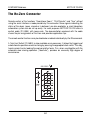
The Re-Zero Connector ................................................................................. 84
Data Format ................................................................................................. 85
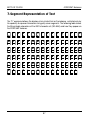
7-Segment Representation of Text ................................................................. 87
What if… ..................................................................................................... 88
1st Aid Kit .................................................................................................... 91
Glossary ...................................................................................................... 93
3
AT/MT/UMT Balances
METTLER TOLEDO
4
METTLER TOLEDO
AT/MT/UMT Balances
Overview
This manual is not intended to be a course in data communications, but rather to provide
specific information regarding the interface characteristics of the AT/MT/UMT balances. It is
divided into several sections:
•
•
•
•
•
•
•
•
•
•
•
Interface characteristics
Transmission modes
Commands in alphabetical order
Configuration of the interface
RS-232 interface
METTLER TOLEDO CL interface
Interface connectors
Data format
7-segment text representation
If all fails...
Glossary
It is assumed that you have already familiarized yourself with the operating characteristics
of the AT/MT/UMT balance. You should also be aware of what the menus is, how it is
accessed and how the parameter settings can be changed in the configuration register.
Please refer to the Operating Instructions of the AT/MT/UMT if there is any uncertainty.
Note
A comprehensive overview of the METTLER TOLEDO peripheral units and the connection
cables for commercial printers and computers can be found in the brochure Technical
specifications and accessories of the AT/MT/UMT balances.
5
AT/MT/UMT Balances
METTLER TOLEDO
Interface Characteristics
All balances of the AT/MT/UMT series are equipped with a serial interface having the
following parameters:
•
•
•
•
•
Asynchronous transmission
1 Start bit
7 Data bits
1 Parity bit (selectable)
1 Stop bit
Depending on the application, you may select between unidirectional and bidirectional data
transmission and between current and voltage operation. This section briefly describes the
various modes.
Unidirectional Mode
In this mode data can be transmitted between a balance and a peripheral device in one
direction only. (Example: to a simple printer).
Bidirectional Mode
Data can be exchanged in both directions. Typical application: A computer requests a
weighing result by means of a command; as soon as the result is available the balance
transmits it back to the computer. Of particular importance here is the concept of break (see
below).
Current Loop Interface
The AT/MT/UMT balance has a passive 20 mA current loop interface. Its use is particularly
attractive in situations where relatively large distances (several hundred feet) have to be
covered. An additional feature is the high immunity to an electrically noisy environment.
However, most off-the-shelf personal computers are not equipped to handle current loop
operation.
6
METTLER TOLEDO
AT/MT/UMT Balances
Voltage-controlled Interface (RS-232)
This popular interface, which is found almost universally in data-processing equipment, is
fully supported by the AT/MT/UMT balances.
Break
The situation where the interface input of the balance is inactive for longer than the duration
of a single character (i.e. current interrupted or voltage level positive) is called a break.
Computers can produce this condition under program control; many terminals are equipped
with a special break key. Disconnecting the data cable or switching off the peripheral device
obviously also generates a break in the current loop mode. With the RS-232 interface, the
positive voltage value needed is, in general, not created on the data line. However, special
electronic circuitry in the AT/MT/UMT balance ensures that the break can still be recognized.
As a result of a break, all changes in the balance parameters resulting from interface
commands are cancelled. The balance returns to the condition it was in before it was
switched on.
The minimum duration of the break depends on the baud rate; 100 ms or longer suffice for
the AT/MT/UMT balances in all cases.
When a break is present, the I/O symbol in the balance display is turned off. A flashing
symbol in the CL handshake mode means that there is an active input line but no full,
bidirectional handshake has been set up.
Handshake
In most systems data can not be transmitted at an arbitrary rate and at all times. A
handshake protocol ensures orderly data flow in such cases. The AT/MT/UMT balance can
operate not only with software control characters but also with special control lines.
7
AT/MT/UMT Balances
METTLER TOLEDO
Galvanic Isolation
All interface connections of the AT/MT/UMT balance are isolated electrically from the rest of
the electronics. This elaborate measure effectively shields the measurement circuits from
electrical noise, which could otherwise enter the balance via the attached peripheral
devices. Furthermore, there is no way for loop currents, resulting from differing potentials
of the system devices (balance, computer), to flow along the data lines.
Only the shielded conductor of the data cable is connected galvanically to the balance case
and therefore to the equipment grounding conductor of the balance.
It is generally recommended to connect the shield to the case on the computer side, too.
This ensures optimum protection from both irradiation and radiation. If problems arise as
a consequence of too high currents circulating in the shield, the connection between shield
and case may be cut on the computer side.
8
METTLER TOLEDO
AT/MT/UMT Balances
Transmission Modes
The balance can be set to transmit results in a variety of ways:
“Print” (Transfer) Key
When the “Print” key is pressed, the balance sends the next stable or the current result,
depending on the configuration of the Send parameter (S.Stb, S.ALL, S.Cont, S.Auto). If only
stable results are to be transmitted and “doorAuto” is configured in the menu, the draft shield
doors close automatically. At the same time the caution (triangle) symbol in the display
lights up. After the transmission, a brief beep sounds and the doors open again. The result
is held in the display for five seconds with a small ring symbol flashing to its right.
The print command can be cancelled anytime while waiting for the weighing result to
achieve stability by pressing the “Print” key.
In contrast to result strings based on the Send commands, those triggered by the “Print” key
always begin with a space character.
External Switch
Transmission of a result may also be initiated by providing a low-resistance connection
between the two pins 11 and 14 of the “Re-Zero” connector at the rear of the balance. The
rules are the same as those described above. As before, the command can be cancelled
by pressing the “Print” key.
9
AT/MT/UMT Balances
METTLER TOLEDO
Automatic
If the one of the send modes “S.Cont” or “S.Auto” has been configured in the “Interface” sector
of the configuration register, data transmission occurs either continuously or automatically
after each load change; this is also the case if one of the interface commands “SIR”, “SNR”
or “SR” is active.
Request by Interface
Interface commands such as “S” or “SI” cause the transmission of a single measured value.
10
METTLER TOLEDO
AT/MT/UMT Balances
Command Overview
Command Naming
All commands appear in alphabetical order with the command name clearly emphasized
in the upper left corner of the page. This helps in easily locating a specific description.
If the command name for a certain feature is unknown, the following tips may be helpful:
Commands that prompt the balance to send something begin with an S.
Commands that communicate something to the user, whether by a change in the display
or by an audible signal, begin with a D.
Commands that influence the mode of the balance, for example, by setting the vibration
adapter or the stability detector, begin with an M.
The remaining commands, which are not as easily categorized, use – wherever possible
– a mnemonic abbreviation (like “T” for tare, “CFG” for configuration etc.).
Command Action
With one exception, all interface command changes affect the balance only temporarily.
After the balance or the computer has been switched off, or after a break on the data line,
the original settings of the user reappear. A special command may be used, if required, to
store the changed settings permanently in the balance.
11
AT/MT/UMT Balances
METTLER TOLEDO
Command Format
Commands consist of one or more characters of the ASCII character set. Non-printable
characters are not used (except Control-G which sounds the balance's beeper). No
distinction is made between uppercase and lowercase letters, except in commands where
this is significant, like in the text argument of the “D text ” command.
The line end (EOL) is either a single return (ASCII 13) or a return followed by line feed (ASCII
10), depending on the EOL parameter selected in the configuration register.
The syntax of the commands is as follows:
CF[ param1 |param2 [ param3 |param4]]
CF represents the command name.
Square brackets [ ] enclose optional parameters. If left out, a preset (default) value is used.
Parameters written in italics represent values whose allowed range is specified in the
command description.
Parameters that are separated by a vertical line ( | ) represent a choice. Only one of the
possible values can appear in the command; combinations are illegal.
The ellipsis (...) means that the preceding parameter may be repeated several times.
Valid variations of the above sample command would thus be:
CF
CF
CF
CF
CF
param1
param2
param1 param3
param1 param4
12
METTLER TOLEDO
AT/MT/UMT Balances
But not:
CFparam1
CF param3
CF param1 param2
(no space after command name)
(param3 or param4 allowed only after param1
or param2)
(either param1 or param2 allowed, but not both)
Error Messages
If the balance cannot process a command, it reports the reason as follows:
ES (Error Syntax)
The command is incorrectly built, or it does not exist.
Example: U 1.5U2.
EL (Error Logical)
executed.
Although the command is syntactically correct, it can’t be
Example: U 0 (division by zero!)
ET (Error Transmission)
One or more characters of the command show a parity error.
The conditions that lead to an EL error are listed under the individual commands.
Restrictions
Communication with the balance is suspended as long as the user is acessing the
configuration register. The peripheral is informed as follows:
CFG BEGIN (Configuration Begin). This message means that the configuration register
has just been called up. Depending on the handshake mode, the balance inhibits command
input by deasserting the handshake signal.
CFG END (Configuration End). The user has made changes in the configuration register
and pressed the “Set” key.
13
AT/MT/UMT Balances
METTLER TOLEDO
CFG STOP (Configuration Stop). The user has pressed the “Cancel” key, or the “Set” key
without changing a parameter, or no key has been pressed for one minute. No change in
the configuration has occurred.
Note: The command CFG (and also Rn or RK) may be used to inhibit the user from
changing the configuration while an application is running. Using the CFG command has
the advantage that the user is informed by the message “Conf off” when trying to access
the configuration register.
Another condition that suspends communication is the calibration cycle. Similar messages
are generated in this case:
CAL BEGIN (Calibration Begin). The calibration cycle has just been started.
CAL END (Calibration End). The calibration cycle has been completed successfully; the
balance is recalibrated.
CAL STOP (Calibration Stop). The calibration cycle has been stopped prematurely by
Cancel key or by the abort command ( . ).
CAL ERROR (Calibration Error). The calibration cycle has been aborted as result of an error
condition.
The Calibration Status command (CA S) works even while calibration is under way.
After a temporary break in the power line, the balance shows “Off”. The only command that
is accepted in this situation is “T”, which will restore normal balance operation.
14
METTLER TOLEDO
AT/MT/UMT Balances
An Example
The example below shows how the balance can be set up for a particular application
through a series of commands. The assignment is to check boxes containing 100 parts
weighing 0.25 g each. Overfilling by three parts or underfilling by one part is tolerated. The
weight of the box is 21.5 g. The weighing results are to be transmitted automatically.
Command
Action
@
Resets the balance to the power-on state.
UX g
Ensures that the weight unit is grams.
RG F
Switches to the fine range. If the balance cannot
be switched, the error message “EL” will appear here.
AD 1
Turns automatic draft shield operation on.
T
Tares the balance; the draft shield is closed, then
reopened automatically.
B 21.5
Subtracts the box’s weight. The net weight symbol “N”
appears in the display.
U0 .25 pcs
Divides all subsequent weight results by the piece weight
0.25 g. The display appears without decimal digits; the unit
is “PCS”.
DY 25 .75 .25
The target weight is 25 g (100 x 0.25 g). The acceptable
positive deviation is 3 pieces (0.75 g), the negative deviation
1 piece (0.25 g).
SR 5
After every weight change of 5 g, the balance sends one
unstable result and then the next stable one.
15
AT/MT/UMT Balances
METTLER TOLEDO
16
METTLER TOLEDO
AT/MT/UMT Balances
Commands
AD ................... AutoDoor ............................................................................................................
B ..................... Base ..................................................................................................................
CA ................... Calibration .........................................................................................................
CFD ................. Set Default Configuration ......................................................................................
CFE ................. Store Configuration in EAROM ...............................................................................
CFG ................. Control Configuration Access ................................................................................
CFP ................. Print Configuration ..............................................................................................
CFR ................. Return Configuration as String ..............................................................................
CFW ................ Write Configuration to Balance ..............................................................................
D ..................... Display Text .......................................................................................................
DB ................... Generate Beep Sound ..........................................................................................
DST ................. Control Display Status Symbols ............................................................................
DSX ................. Select Active Display ............................................................................................
DX ................... Control DeltaTrac Display .....................................................................................
DY ................... Weighing-in .......................................................................................................
EC ................... Command Acknowledge ......................................................................................
EOL ................. End-of-Line Mode ................................................................................................
HS ................... Handshake Mode ................................................................................................
ID .................... Balance Identification ..........................................................................................
IDX .................. User Identification ................................................................................................
M .................... Mode Reset ........................................................................................................
MD .................. Readout Increment ..............................................................................................
MI ................... Vibration Adapter (“Wave”) ..................................................................................
ML ................... Weighing Process Adapter (“Drop”) ......................................................................
MS ................... Stability Detector (ASD) ........................................................................................
MT ................... Serial Transmission Mode ....................................................................................
MZ ................... AutoZero ............................................................................................................
RG ................... Range Select ......................................................................................................
RK ................... Keyboard Control (Single Keys) ............................................................................
Rn ................... Keyboard Control (Global) ...................................................................................
RX ................... Disabling/Enabling of the External Switches ...........................................................
S ..................... Send Stable Result ..............................................................................................
SI .................... Send Immediate Result ........................................................................................
SIR .................. Send Continuously ..............................................................................................
SNR ................. Send Automatically ..............................................................................................
SR ................... Send Automatically with Threshold ........................................................................
T ..................... Tare ...................................................................................................................
U ..................... Select Unit or Divisor ...........................................................................................
US ................... Select Active Unit .................................................................................................
UX ................... Redefine Units .....................................................................................................
W .................... Control Output Module .........................................................................................
WI ................... Control Draft Shield .............................................................................................
@ .................... Cancel Mode Changes .........................................................................................
? ..................... Help ..................................................................................................................
. ...................... Abort Lengthy Command Execution .......................................................................
<crlf> .............. Repeat Last Valid Command ................................................................................
17
18
19
20
22
23
24
25
26
27
28
30
31
32
33
34
35
36
37
38
39
40
41
43
44
45
46
47
48
49
50
51
52
53
54
55
56
57
58
60
61
62
64
65
66
67
68
AT/MT/UMT Balances
METTLER TOLEDO
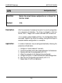
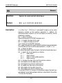
AD
AutoDoor
Function:
Turns the automatic draft shield operation on or off.
Format:
AD[ n|?]
Description:
n is either 0 or 1.
AD 0 turns the automatic draft shield operation off.
AD 1 turns it on.
AD without parameter selects the factory setting.
AD ? reports the present setting as follows:
AD=0
automatic operation off
AD=1
automatic operation on
18
METTLER TOLEDO
AT/MT/UMT Balances
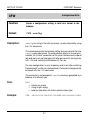
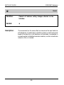
B
Base
Function:
Subtracts a constant weight value from all
weighing results (tare preset).
Format:
B[ offset]
Description:
offset is a positive weight value, expressed in the current weight
unit 1. This value is subtracted from all future weighing results. The
net weight symbol N identifies the mode in the display.
The sum of offset and any tare value must not exceed the
maximum load range of the balance.
B without parameter returns to the normal weighing operation without
tare preset.
Examples:
B 20
Subtracts 20 g from each weighing result (if unit 1 is set to grams).
UX oz
B .245
Subtracts 0.245 oz from each weighing result.
The stored tare preset is not affected by unit changing.
Error:
EL if
• offset negative
• tare plus offset greater than maximum load
19
AT/MT/UMT Balances
METTLER TOLEDO
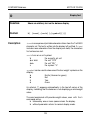
CA
Calibration
Function:
Triggers the automatic calibration or calibration test, changes
the calibration mode, returns calibration status.
Format:
CA[ n|U|S|T|?]
Description:
n is either 0 or 1.
CA starts the automatic internal calibration and linearization.
CA 0 sets the mode CALIN “Auto off” (the internal calibration is
launched by the user or through the CA command).
CA 1 sets the mode CALIN “Auto on” (fully automatic calibration).
CA U sets the mode CAL “User” (calibration with external reference
weight).
CA ? sends the currently set mode as follows:
CA=0
mode “Auto off”
CA=1
mode “Auto on”
CA=U
mode “User”
A calibration operation in progress can be aborted with the cancel
command “.” .
20
METTLER TOLEDO
AT/MT/UMT Balances
CA S sends the current calibration control status as follows:
CA=I
“Idle”; no automatic calibration pending
CA=W
“Waiting”; automatic calibration cycle will occur at the
next possible opportunity. The AUTOCALIN symbol is
lit.
CA=CA Automatic calibration is in progress.
CA=CX Calibration has been started manually or by command.
CA=CT Calibration test is running.
This command may be issued even while a calibration cycle is in
progress.
CA T starts the calibration test. The internal weights are put on the
pan. The display alternates between the weight and the message
“test”. The weight may be read out using normal send commands.
The test mode is left automatically after one minute, or by issuing the
cancel command, or by pressing the tare or cancel key.
Error:
EL with CA or CA T command if “Cal User” has been configured,
or if a calibration or test cycle is already in progress.
21
AT/MT/UMT Balances
METTLER TOLEDO
CFD
Configuration Defaults
Function:
Sets all balance parameters, except those for the serial
interface, to the factory setting.
Format:
CFD
Description:
CFD essentially causes resetting of the balance to the standard
configuration. The following parameters are affected:
• vibration adapter (wave symbol)
• weighing process adapter (drop symbol)
• stability detector (ASD)
• AutoZero
• automatic draft shield operation
• calibration mode
• automatic turning-off of the status displays
• sound generation (on or off)
• balance resolution (readout increment)
• weight units 1 and 2
• “nationality” of weight unit tael
The parameters for the serial interface remain unchanged in order to
avoid disrupting communication with the peripheral device.
22
METTLER TOLEDO
AT/MT/UMT Balances
CFE
Store Configuration
Function:
Saves the current configuration in the permanent
memory (EAROM) of the balance.
Format:
CFE
Description:
Most settings in the configuration register of the balance as well as
the weighing parameters (vibration and weighing process adapters)
can be changed with suitable interface commands. The changes are
lost, however, when the balance is switched off or an interface break
occurs.
With the CFE (Configuration to EAROM) command the changes can
be permanently stored in the balance. This includes all changes that
the user has made directly to the balance.
Error:
EL if the storing failed (e.g. defective memory).
23
AT/MT/UMT Balances
METTLER TOLEDO
CFG
Configuration Access
Function:
Controls the user’s access to the configuration register.
Format:
CFG[ n|?]
Description:
n is either 0 or 1.
CFG 0 inhibits the user from accessing the configuration register.
CFG 1 allows access to the configuration register, provided the
jumper in the program cassette is set to the “unprotected” position.
CFG without parameter selects the access mode according to the
jumper in the program cassette.
CFG ? sends the currently set mode as follows:
CFG=0 no access
CFG=1 access allowed
Any attempt to access the configuration register while access is
denied will result in the message “conf off” shown on the balance
display.
Error:
EL with CFG 1 command if the program cassette jumper is in the
“protected” position.
24
METTLER TOLEDO
AT/MT/UMT Balances
CFP
Configuration Print
Function:
Prompts the balance to send the contents of the
configuration register.
Format:
CFP
Description:
After CFP the balance sends the contents of the configuration register
as normal text. Note that this information does not necessarily reflect
the current configuration since that could have been changed
temporarily by interface commands. The configuration supplied is
that which is permanently stored in the balance, and which is valid
immediately after the balance has been switched on. The actual
current settings may be recalled by the appropriate commands (e.g.
MS ?).
A typical configuration is transmitted as follows:
S T O R E D
S E T T I N G S
SCALE:
Stability Detector (ASD): -3Display Resolution (dC) : step by 1
Display Resolution (dF) : step by 1
AutoZero
: on
Calibration Method
: internal auto
UNIT:
Unit 1
Unit 2
Display Symbols
Sound
:
:
:
:
g
%
auto-off
on
INTERFACE:
Weight Send Method
Baudrate
Parity
Handshake Method
End-of-line
:
:
:
:
:
stable only (S)
2400
even
Pause after line
CRLF
——
25
(coarse range)
(fine range)
AT/MT/UMT Balances
METTLER TOLEDO
CFR
Configuration Read
Function:
Returns the current balance configuration as a string in the
Intel hex format.
Format:
CFR
Description:
After this command, the balance transmits its current configuration
as a sequence of characters. The string is arranged in Intel hex
format, that is, it begins with a colon and ends with a checksum.
CFR is usually used in tandem with the CFW (Configuration Write)
command. Together they allow the reading, storing and writing of a
complete balance configuration in a computer.
Application:
A number of balances may be configured identically following the
procedure outlined below:
1.
2.
3.
4.
5.
6.
7.
Configure a “master balance” manually.
Connect a portable hand-held or laptop computer to the balance.
Receive and store the configuration with CFR.
Attach the computer to the balance to be configured.
Configure using the CFW command and the stored configuration.
Store the new configuration permanently with CFE.
Repeat steps 4 to 6 for all balances.
26
METTLER TOLEDO
AT/MT/UMT Balances
CFW
Configuration Write
Function:
Sends a configuration setting in Intel hex format to the
balance.
Format:
CFW config
Description:
config is a string in the Intel hex format, usually acquired by using
the CFR command.
This command selects the balance setting that was valid at the time
config was determined. To avoid adverse effects on the communication, the “critical” parameters of the serial interface such as baud
rate and parity are not changed until after permanently storing them
with CFE and switching the balance off, then on.
The new configuration is only temporary and is lost after switching
the balance off, or after an interface break. Permanent storage can be
achieved with the CFE command.
The command is not accepted if config has been generated by a
balance of a different type.
Error:
EL if
• checksum wrong
• string length wrong
• balance type does not match already stored type
Example:
CFW :0E00000041250F010000BA53020200E000008B
27
AT/MT/UMT Balances
METTLER TOLEDO
D
Display Text
Function:
Shows an arbitrary text on the balance display.
Format:
D[ [text[;[unit][;[symbol]]]]]
Description:
text is a sequence of printable characters taken from the 7-bit ASCII
character set. The text is written into the display left-justified. If text
includes more characters than the display can hold, the characters
first entered are lost.
unit turns on a unit symbol:
U
# or PCS
Stk
%
the currently set unit
the unit “PCS”
the unit “Stk”
the symbol “%”
symbol can be used to show one of the four weight symbols on the
display:
B
N
T
G
Brutto (German for gross)
Net
Tare
Gross
An asterisk (*) appears automatically in the top left corner of the
display, indicating that the balance is not displaying a valid weight
value.
The send commands still provide weight values, even with the D
command active.
D followed by one or more spaces clears the display.
D without parameter returns to normal display mode.
28
METTLER TOLEDO
D
Zweck:
Examples:
Format:
AT/MT/UMT Balances
Display
Text
Many characters of the ASCII set can be represented only
roughly
with
seven segments. The section “7-Segment Representation of Text” in
the Appendices contains a list of the symbols used.
Zeigt einen beliebigen Text auf der Waagenanzeige.
D HALLO
D -23.5;%
D Net;;n
D[ [text[;[unit][;[symbol]]]]]
29
AT/MT/UMT Balances
METTLER TOLEDO
DB
Beep
Function:
Controls the built-in sound generator.
Format:
DB[ n|C|E]
Description:
n is a natural number in the range 0 to 3.
With this command, the user can be alerted in a variety of ways.
DB without parameter generates a short signal.
DB 1 generates a long signal.
DB 2 produces a double beep.
DB 3 triggers a long signal, followed by a short one.
DB C produces the termination signal (“Cancel”) specific to the AT,
which is the same as that resulting from pressing the tare key for more
than three seconds.
DB E generates the AT/MT/UMT-specific error signal (“Error”).
All commands shown above change the beep setting to “Beep On”.
After a break, or after the balance has been switched off, the original
user setting is restored.
DB 0 suppresses all sound generation in the balance, even if “Beep
On” has been configured.
Reception of ASCII-BEL (Hex 7, Control-G) also produces a short
beep.
30
METTLER TOLEDO
AT/MT/UMT Balances
DST
Display Status
Function:
Controls the behavior of the status indicators for
vibration adapter (wave symbol), weighing process
adapter (drop symbol) and interface (I/O symbol).
Format:
DST[ n|A|?]
Description:
n is either 0 or 1.
Depending on the configuration, the status indicators are either
permanently on or turned off automatically a few minutes after the
balance has been switched on. This behavior can be changed with
the DST command.
DST 0 clears the symbols immediately.
DST 1 keeps the symbols on permanently.
DST A switches the symbols on. They will turn off automatically after
about three minutes.
DST without parameter selects the factory setting.
DST ? sends the current status as follows:
DST=0 symbols off
DST=1 symbols on
DST=A symbols on, will be turned off soon
31
AT/MT/UMT Balances
METTLER TOLEDO
DSX
Display Select
Function:
Selects the active display if an auxiliary display is
attached.
Format:
DSX[ n]
Description:
n is either 0 or 1.
If an auxiliary display (e.g. GT53) is attached to the balance, DSX
can be used to ensure that only the balance display, only the remote
display, or both together are controlled by the balance.
DSX 1 activates the balance display. The last result obtained
remains “frozen” on the auxiliary display.
DSX 2 activates the auxiliary display. The last balance display
remains “frozen”.
DSX 0 switches both displays back to synchronous operation.
DSX without parameter works the same as DSX 0.
Note:
DSX can only be used with LCD displays.
32
METTLER TOLEDO
AT/MT/UMT Balances
DX
DeltaTrac
Function:
Controls the DeltaTrac display.
Format 1:
Format 2:
DX[ pos1[ pos2|-pos2][ T]]
DX T|C
Description:
pos1 and pos2 are natural numbers in the range 0 to 60.
With DX, one or two segments or any continuous range of the Mettler
DeltaTrac display may be activated. The segments are numbered in
the same manner as the minutes of a clock.
DX pos1 activates the segment pos1.
DX pos1 pos2 shows two individual segments.
DX pos1-pos2 shows all segments from pos1 in clockwise
direction up to and including pos2.
In addition, if the parameter T is specified, the tolerance markers are
shown.
DX T shows the tolerance markers only.
DX C clears all DeltaTrac elements.
Error:
EL if pos1 or pos2 not in the range 0 to 60.
Examples:
DX 5
DX 10 50
DX 10-50
DX 50-10 T
33
AT/MT/UMT Balances
METTLER TOLEDO
DY
Weigh In
Function:
Defines target weight and tolerances for checkweighing using
the Mettler DeltaTrac.
Format 1:
Format 2:
DY[ target[ tol+[ tol-]][ S]]
DYB[ target[ tol+[ tol-]][ S]]
Description:
target, tol+ and tol- are positive weight values expressed
in the current weight unit 1.
After receipt of the DY command checkweighings can be performed
with the balance as described in the operating instructions of the
AT/MT/UMT under “Percent weighing”. In contrast to that application,
however, weight values continue to be displayed. In addition, the
tolerances are not fixed to ±2.5% but can be specified separately for
positive and negative deviations. Any tare preset must be added to
the target weight using the B command. If this is not desired, the DYB
command may be used.
If tolerances are not specified then tol+ = tol- = 2.5% of
target. If tol- is omitted it assumes the same value as tol+.
DY or DYB without parameter clears the application.
S causes a double beep as well as automatic transmission of the
weight as soon as stability is reached and the weight is inside the
tolerance limits.
Error:
EL if:
•
•
•
•
•
one or more parameters negative
target weight plus tare is larger than maximum load
target weight is less than 0.01 g
tolerance value is less than 0.0005 g
one of the built-in applications is active
34
METTLER TOLEDO
AT/MT/UMT Balances
EC
Command Acknowledge
Function:
Turns the command acknowledge mode on or off.
Format:
EC[ n|?]
Description:
n is either 0 or 1.
EC 1 turns command acknowledge on. This causes the balance to
send the message OK after every command that it has recognized
as correct. This signifies that it is ready for a new command.
EC 0 or EC without parameter switches back to normal mode (no
acknowledge).
EC ? reports the current mode as follows:
EC=0
command acknowledge off
EC=1
command acknowledge on
An OK message does not necessarily mean that the command has
been fully executed. With the tare command, for instance, OK
appears as soon as taring begins. With an unstable weighing signal,
however, it can take several seconds until the display has achieved
stability and taring can be completed.
Error messages (EL, ES or ET) override the OK message.
Error:
EL if the handshake mode is set to METTLER TOLEDO CL. In this
mode the character ACK assumes the role of the OK message.
35
AT/MT/UMT Balances
METTLER TOLEDO
EOL
End-of-Line Mode
Function:
Selects the end-of-line mode.
Format:
EOL[ mode|?]
Description:
mode is either CR or CRLF.
With this command the end-of-line mode can be chosen. Use of this
option is described in the section “End-of-Line”.
EOL CR selects the mode “Carriage Return is End-of-Line”.
EOL CRLF selects the mode “Carriage Return plus Line Feed is Endof-Line”.
EOL without parameter selects the factory setting.
EOL ? reports the current setting as follows:
EOL=CR
EOL=CRLF
Error:
EL if an attempt is made to set “CR” in the CL handshake mode.
36
METTLER TOLEDO
AT/MT/UMT Balances
HS
Handshake Mode
Function:
Selects the handshake mode.
Format:
HS[ mode|?]
Description:
mode is one of the modes hard, soft, Pause, CL or off.
HS hard selects the mode which uses the handshake lines DTR and
CTS.
HS soft selects the mode which uses the handshake signals XON
and XOFF.
HS Pause selects the mode which inserts a pause (1s) after every
line sent.
HS CL selects the METTLER TOLEDO CL handshake mode.
HS off turns any handshake off.
HS without parameter selects the factory setting.
HS ? reports the current setting as follows:
HS=hard
HS=soft
HS=Pause
HS=CL
HS=off
37
AT/MT/UMT Balances
METTLER TOLEDO
ID
Identification
Function:
Prompts the balance to transmit an identification text.
Format:
ID
Description:
ID is useful in a weighing system if the controlling instrument
(computer) needs to know the type and the version of the attached
balance.
The AT balance sends a three-line (four-line*) identification similar
to the following example:
STD 10.1.09
TYPE : AT 250
0.00.00
SNR : 1234567890*
The first line denotes the type and version of the software in the
program cassette, the second denotes the balance model, and the
third helps in recognizing special national and customized versions.
* The fourth line is only available with balance software version 1.23
and states the serial number of the balance.
38
METTLER TOLEDO
AT/MT/UMT Balances
IDX
Extended Identification
Function:
Handles the reading and writing of a user-definable identification string.
Format:
IDX[ id]
Description:
id is an identification string consisting of exactly seven characters
as follows:
cnnnnnn
where:
c = alphabetic character (a…z or A…Z)
n = hexadecimal character (0…9 or A…F)
This command allows the user to store an arbitrary string (within the
restrictions shown above) in the balance. This may be useful in a
system where several balances are connected to a common controller.
IDX id stores id permanently in the balance.
IDX without parameter returns the currently stored identification
string.
When leaving the factory, the balance contains a unique identification
string. Once overwritten by the user, there is no way to retrieve this
original value.
Error:
EL if id contains an illegal character, i.e. not in the range specified
above.
39
AT/MT/UMT Balances
METTLER TOLEDO
M
Mode Reset
Function:
Sets the vibration adapter (wave symbol), the weighing
process adapter (drop symbol), the stability detector (ASD),
the AutoZero (AZ), and the readout increment (d) to the
factory setting.
Format:
M
Description:
With the M command a control unit can easily make sure that the
balance is in a known state. It has the same effect as calling the six
commands MD, MI, ML, MS, MT and MZ in a row, each without
parameters.
40
METTLER TOLEDO
AT/MT/UMT Balances
MD
Readout Increment
Function:
Modifies the readout increment.
Format 1:
Format 2:
MD[ step|?]
MD[[ F| C] ?] and MD[ F|C[ step]]
Description:
step is a natural number from the series 1, 2, 5, 10.
MD allows the reading and modifying of the readout increment
parameter of the configuration register.
Format 1: (single range balances)
For balances with only one weighing range, format 1 applies.
MD step sets the readout increment to the value step.
MD without parameter selects the factory setting.
MD ? sends the current setting as follows:
MD=step readout increment set to position step
Format 2: (multiple range balances)
For balances with several weighing ranges, format 2 applies. The
letter F specifies the fine range, the letter C the coarse range.
41
AT/MT/UMT Balances
METTLER TOLEDO
MD F step sets the readout increment of the fine range to the value
step.
MD C step sets the readout increment of the coarse range to the
value step.
MD F sets the readout increment of the fine range to the factory
setting.
MD C sets the readout increment of the coarse range to the factory
setting.
MD F ? sends the current setting of the fine range as follows:
MD F=step
readout increment at position step
MD C ? sends the current setting of the coarse range as follows:
MD C=step
readout increment at position step
MD without parameter selects the factory setting for both ranges.
MD ? sends the current setting as follows:
MD C=step F=step
Error:
EL if the range specified with F or C is not available.
Example:
The fine range of a dual range balance is to be set to a readout
increment of 5, the coarse range to 2.
MD F 5
fine range
MD C 2
coarse range
MD ?
query
MD C=2 F=5 balance response
42
METTLER TOLEDO
AT/MT/UMT Balances
MI
Vibration Adapter
Function:
Modifies the vibration adapter (wave symbol).
Format:
MI[ n|?]
Description:
n is a natural number in the range 1 to 3.
n =1: vibration-free environment (small wave symbol)
n =2: normal environment (medium wave symbol)
n =3: severe vibrations (large wave symbol)
MI n sets the vibration adapter to the value n.
MI without parameter selects the factory setting.
MI ? sends the current setting as follows:
MI=n
vibration adapter at position n
43
AT/MT/UMT Balances
METTLER TOLEDO
ML
Weighing Process Adapter
Function:
Modifies the weighing process adapter (drop symbol)
Format:
ML[ n|?]
Description:
n is a natural number in the range 0 to 3.
n =0:
n =1:
n =2:
n =3:
no adaption
dispensing
universal setting
absolute weighing
ML n sets the weighing process adapter to the value n.
ML without parameter selects the factory setting.
ML ? sends the current setting as follows:
ML=n
weighing process adapter at position n
44
METTLER TOLEDO
AT/MT/UMT Balances
MS
ASD
Function:
Modifies the stability detector (ASD).
Format:
MS[ n|?]
Beschreibung:
n is a natural number in the range 0 to 7.
MS n sets the stability detector to level n.
MS 0 disables the stability detector (position “off”).
MS without parameter selects the factory setting.
MS ? sends the current setting as follows:
MS=n
stability detector at level n
45
AT/MT/UMT Balances
METTLER TOLEDO
MT
Transmission Mode
Function:
Modifies the data transmission mode (“Send Mode”)
Format:
MT[ mode]
Description:
mode is either Stb, All, Auto, or Cont.
MT Stb selects the mode “Send Stable”.
MT All selects the mode “Send All”.
MT Auto selects the mode “Send Auto”.
MT Cont selects the mode “Send Cont”.
MT without parameter selects the factory setting.
MT ? sends the current setting as follows:
MT=mode
46
METTLER TOLEDO
AT/MT/UMT Balances
MZ
AutoZero
Function:
Turns AutoZero (AZ) on or off.
Format:
MZ[ n|?]
Description:
n is either 0 or 1.
MZ 0 turns AutoZero off.
MZ 1 turns AutoZero on.
MZ without parameter selects the factory setting.
MZ ? sends the current setting as follows:
MZ=0
AutoZero off
MZ=1
AutoZero on
47
AT/MT/UMT Balances
METTLER TOLEDO
RG
Range Select
Function:
Selects the weighing range.
Format:
RG[ C|F|?]
Description:
With multiple-range balances RG can be used to select the weighing
range.
RG C selects the coarse range (resolution 0.1 mg)
RG F selects the fine range (resolution 0.01 mg)
RG without parameter toggles between fine and coarse range, like the
front panel key.
RG ? reports the current setting as follows:
RG=C
coarse range active
RG=F
fine range active
Error:
EL if
• RG, RG C, or RG F used with single range balance
• Trying to set the fine range when fine range limit exceeded
48
METTLER TOLEDO
AT/MT/UMT Balances
RK
Restrict Keyboard
Function:
Allows disabling or enabling of individual balance frontpanel keys.
Format:
RK[ bbbbbbbb]
Description:
Each b represents a single key and can have the value 0 or 1. From
left to right the following assignments apply:
Re-Zero On/Off Print Menu 0.1/0.01 mg
Select 2 Select 1
A “0” in the corresponding position disables the key, a “1” enables
it.
Re-Zero refers to pressing the «On/Off» key, On/Off refers to lifting this
key.
The symbol REMOTE is shown on the display as long as at least on
of the keys is disabled.
RK without parameter enables all keys, with the exception of the door
keys which are disabled by a WI D command.
RK ? reports the current setting as follows:
RK=bbbbbbbb
Error:
EL if the parameter does not contain exactly eight 0’s or 1’s.
Example:
RK 00100011
Disables all keys except “Print” and the door keys. Note that the
balance can no longer be switched off by the user.
49
AT/MT/UMT Balances
METTLER TOLEDO
Rn
Remote
Function:
Allows simultaneous disabling or enabling of all balance
front-panel keys.
Format:
R0|R1
Description:
R0 enables the keys except for the door keys if they have been
disabled by a WI D command.
R1 disables all keys.
This command has been kept for compatibility reasons. The RK
command serves the same purpose, at the same time offering much
more flexibility.
The symbol REMOTE is shown on the display as long as the keys are
disabled.
50
METTLER TOLEDO
AT/MT/UMT Balances
RX
Restrict External Switches
Function:
Allows the individual disabling or enabling of the
external switches (connection “Re-zero”)
Format:
RX[ bbbbbbbb]
Description:
Each b represents a single switch and can have the value 0 or 1.
From left to right the following assignments apply:
x
x
x
x
x
Doors
Transfer
Tare
A 0 in the corresponding position disables the switch, a 1 enables it.
The positions marked with x are unassigned and are ignored by the
balance.
RX without parameters allows all switch functions again.
RX ? reports the current setting as follows:
RX=bbbbbbbb
Error:
EL if the parameter does not contain exactly eight 0’s or 1’s.
Example:
RX 11111010
Disables the switches for taring and door operation. However, the
transfer switch remains operative.
51
AT/MT/UMT Balances
METTLER TOLEDO
S
Send Stable
Function:
Prompts the balance to send a single stable weighing
result.
Format:
S
Description:
This command causes the balance to send the next stable weighing
result. If the balance is already stable when receiving the command,
transmission occurs immediately. The data string begins with “S ” ,
identifying a stable result.
An overload condition returns SI+, underload returns SI–.
Any existing send command is cancelled by S.
The data format is described in the section “Data Format”.
The S command is equivalent to pressing the Print key when the
transmission mode “Send Stable” is configured.
52
METTLER TOLEDO
AT/MT/UMT Balances
SI
Send Immediate
Function:
Prompts the balance to send a single weighing result
immediately, regardless of the stability status.
Format:
SI
Description:
After receipt of this command the balance immediately transmits the
next weighing result without waiting for stability. The data string
begins with “S ” if the weight value is stable, with “SD” if it is unstable.
If no valid result can be transmitted at the moment (the balance might
be waiting for stability, showing only hyphens), the message SI is
sent instead.
Overload is reported as SI+, underload as SI–.
Any existing send command is cancelled by SI.
The data format is described in the section “Data format”.
The SI command is equivalent to pressing the Print key when the
transmission mode “Send All” is configured.
53
AT/MT/UMT Balances
METTLER TOLEDO
SIR
Send Immediate and Repeat
Function:
Prompts the balance to continuously send weighing results,
regardless of the stability status.
Format:
SIR
Description:
After receipt of this command the balance sends weighing results
continuously (about two and a half results per second) under the
same conditions as the SI command. The data strings begin with
“S ” in the case of a stable weighing result, with “SD” if the weighing
results are unstable.
Invalid results (for example, the balance is waiting for stability and
shows only hyphens) appear as SI.
Overload is reported as SI+, underload as SI–.
Any existing send command is cancelled by SIR.
When using this command, special attention should be paid to the
correct setting of the handshake mode since the receiving device
might otherwise be unable to keep up with the data flow.
The SIR mode can be cancelled simply by sending an SI command
(or by any other send command).
The data format is described in the section “Data Format”.
The SIR command has the same effect as if the balance had been
configured to the transmission mode “Send Continuous”.
54
METTLER TOLEDO
AT/MT/UMT Balances
SNR
Send Next and Repeat
Function:
Prompts the balance to send the next stable weighing result
automatically whenever a load change occurs.
Format:
SNR
Description:
After receipt of this command the balance sends the next stable result
(immediately if it is already stable) and then another one after every
load change of at least 0.01 g.
Overload is reported as SI+, underload as SI–.
Any existing send command is cancelled by SNR.
The data format is described in the section “DataFormat”.
The SNR command has the same effect as if the balance had been
configured to the transmission mode “Send Auto”.
55
AT/MT/UMT Balances
METTLER TOLEDO
SR
Send and Repeat
Function:
Prompts the balance to send an unstable result whenever a load change occurs and then transmit the next
stable weighing result.
Format:
SR[ threshold]
Description:
threshold is a positive weight value in the current unit 1.
After receipt of this command the balance sends the next stable
weighing result (immediately if it is already stable), then an unstable
result after every load change of at least the threshold value, as
an indication that the load on the weighing pan has been changed,
and finally the next stable weighing result. This procedure is constantly
repeated.
The minimum value for threshold is 0.001 g.
If threshold is omitted, a value of 12.5% of the last stable result,
but at least 0.01g, is used.
SR 0 switches the SR mode off.
Overload is reported as SI+, underload as SI–.
Any existing send command is cancelled by SR.
The data format is described in the section “Data Format”.
Error:
EL if
• threshold is negative or less than 0.001 g
• stability detector is switched off (ASD=0)
56
METTLER TOLEDO
AT/MT/UMT Balances
T
Tare
Function:
Tares the balance or switches it on again after a power failure.
Format:
T
Description:
The T command has the same effect as pressing the tare key. If the
weight result is stable or the stability detector is switched off, taring
occurs immediately. Otherwise, hyphens are shown in the display
and results requested by SI or SIR appear as “SI”.
In contrast to manual taring, no TA message is generated.
If the taring process can not be completed within one minute, it is
aborted. The error message EL is sent to the interface.
Following an interruption of the power supply to the balance, T is the
only command accepted. The tare command restores normal balance
operation.
Error:
EL if
• taring not possible within one minute
• overload or underload
57
AT/MT/UMT Balances
METTLER TOLEDO
U
Unit
Function:
Selects a weight unit or a constant divisor for
all weighing results.
Format 1:
Format 2:
U[ unit]
U[dec] div[ name]
Description:
Format 1:
unit is one of the weight units of the AT/MT/UMT balance:
g mg oz ozt tl GN dwt ct C.M. mo
The selected weight unit replaces the previous weight unit 2. Weight
unit 1 is not accessible as long as the U command is active.
Commands that specify a weight value, such as B, DY or SR, still
refer to the original weight unit 1.
The unit tael (tl) uses one of the three national conversion factors, as
selected in the configuration register.
U with no parameter clears the unit and reselects unit 1.
Format 2:
dec is a natural number in the range 0 to 7.
div is a divisor expressed in weight unit 1with or without decimal
places.
name specifies a display symbol as follows:
# or PCS
the symbol “PCS”
Stk
the symbol “Stk” (German for “PCS”)
%
the symbol “%”
If name is omitted, no unit appears.
58
METTLER TOLEDO
AT/MT/UMT Balances
This command allows the conversion of the weighing results into any
“custom” weight unit. The number of decimal places can be selected
with the parameter dec. Omission of dec shows the maximum
possible number of places for the current unit 1.
Error:
EL if div is so small that the display capacity would be exceeded.
Example:
Parts having an average piece weight of 0.125 oz are to be counted:
U oz
change unit 1 to ounces
U0 .125 divisor = 0.125, no decimal places
Note:
If one of the built-in applications (percent weighing or piece
counting) is active at the time of the U command, it will be reset. The
stored reference weight is lost.
59
AT/MT/UMT Balances
METTLER TOLEDO
US
Unit Switch
Function:
Selects the active weight unit.
Format:
US[ n|?]
Description:
n is a natural number, either 1 or 2.
With this command one of the two weight units unit 1 or unit 2 can
be made current.
US n selects the weight unit n.
US without parameter switches to the next weight unit (from 1 to 2,
from 2 to 1). This is equivalent to pressing the corresponding balance
key.
US ? sends the current setting as follows:
weight unit n active.
US=n
Error:
EL if
• U command active
• both weight units identical
• external command active (B, DY, etc.) and weight unit 2
is piece or percent
• weight unit piece or percent selected but no reference weight
stored.
60
METTLER TOLEDO
AT/MT/UMT Balances
UX
Unit Change Extended
Function:
Redefines the weight units 1 and 2.
Format:
UX[ [unit1][;unit2]|?]
Description:
unit1 and unit2 each denote one of the weight units of the
AT/MT/UMT balance:
g mg oz ozt tl GN dwt ct C.M. mo
UX unit1 sets weight unit 1 to unit1.
UX unit1;unit2 sets weight unit 1 to unit1 and weight
unit 2 to unit2. A space character may be used in place of the
semicolon.
UX ;unit2 sets weight unit 2 to unit2.
UX without parameter sets the two weight units to the factory setting.
UX ? sends the current setting as follows:
UX=unit1 unit2
After the changing one or both weight units, the balance switches
automatically to weight unit 1.
Error:
EL if the selected weight unit cannot be displayed (e.g. µg with
analytical balance).
Example:
UX ;oz
US 2
sets weight unit 2 to ounces
activates weight unit 2 (oz)
61
AT/MT/UMT Balances
METTLER TOLEDO
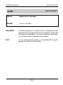
W
Write Output
Function:
Controls the GM54 Output Module or the LV10 Automatic
Feeder.
Format 1:
Format 2:
W[ stat]
W stat time stat[ time stat]…
Description:
Format 1:
stat is a natural number in the range 0 to 255.
With this command the eight digital outputs of the GM54 Output
Module accessory can be switched on and off individually. Each of
the eight outputs is assigned a value as follows:
digital output
digital output
digital output
digital output
digital output
digital output
digital output
digital output
0:
1:
2:
3:
4:
5:
6:
7:
1
2
4
8
16
32
64
128
stat is specified as the sum of the values of those switches that
should be closed. Example: With W 5 the digital outputs 0 and 2 are
closed, all others are opened.
W without parameter opens all eight switches.
A break in the interface line also opens all switches.
Error:
EL if stat is not in the range 0 to 255.
62
METTLER TOLEDO
AT/MT/UMT Balances
Format 2:
stat is a natural number in the range 0 to 255.
time is a natural number in the range 1 to 60,000.
This command can be used to program a series of status changes
of the digital outputs with selectable time intervals. The first and the
last argument are always a stat condition. The time intervals
between the status changes are expressed in milliseconds, with an
actual resolution of about 6 ms. The shortest interval is 15 ms, for
technical reasons, the longest 60 seconds.
The command can handle a maximum of six stat conditions with
five time intervals.
After the entire sequence has been executed, the message WA is sent
to the interface. If the balance receives another W command before
this occurs, the old command is aborted immediately.
Error:
EL if
• stat not in the range 0 to 255
• time not in the range 1 to 60,000
Example:
The following pattern is to be generated:
1s
0.5 s
5s
Output 0
Output 5
W (makes sure all eight switches are open)
W 1 1000 32 5000 33 500 0
63
AT/MT/UMT Balances
METTLER TOLEDO
WI
Windows
Function:
Controls the motorized draft shield doors.
Format:
WI[ n|?|D[F|X]|E[F|X]]
Description:
n is either 0 or 1. With the WI command the doors can be either
opened or closed, or their position requested. In addition, the
mechanical door switches (on the front-panel or external) can be
disabled or enabled.
WI 0 opens the doors.
Special command for MT/UMT balances only:
WI 0 R opens the door to the right
WI 0 L opens the door to the left
Lear function of the MT/UMT balances:
WI 0 opens the door to the same side as the last time it opened electrically
(with the press of a key or with the commands WI 0 R/WI 0 L)
WI 1 closes the doors.
WI without parameter moves the doors (like the front-panel door keys).
WI ? reports the current position as follows:
WI=0
doors open
WI=1
doors closed
WI=2
doors in intermediate position
WI=3
doors moving
WI D disables the door keys and the external switches.
WI DF disables the two door keys only.
WI DX disables the external switches only.
WI E enables all door keys and switches.
WI EF enables the two door keys only.
WI EX enables the external switches only.
The symbol REMOTE is shown on the display as long as the door keys
are disabled. Use of external door switches is described in the section
“The Re-Zero Connector”.
64
METTLER TOLEDO
AT/MT/UMT Balances
@
Break
Function:
Cancels all balance setting changes effected via the
interface.
Format:
@
Description:
This command has the same effect as a break on the input data line
of the balance. It is particularly suited for systems in which a physical
break of the data line is not feasible or not desirable, for example in
a remote control installation based on modems, or when a local area
network (LAN) is involved.
65
AT/MT/UMT Balances
METTLER TOLEDO
?
Help
Function:
Sends an overview of the interface commands.
Format:
?[s]
Description:
Causes the balance to send a list of the major interface commands.
Proper representation requires a video terrminal or computer screen,
or a printer capable of printing at least 80 characters per line.
?D
?F
?E or ?
shows the command list in German.
shows the command list in French.
without parameter shows the command list in
English.
The printout can be cancelled by sending any valid command.
66
METTLER TOLEDO
AT/MT/UMT Balances
.
Cancel
Function:
Aborts a time-consuming command execution.
Format:
.
Description:
Some commands take quite some time to execute or are unable to
finish because of an unstable environment. Rather than wait for a
time-out, these commands may be aborted by the cancel command.
Like all commands, it requires a return character termination (possibly
followed by a line feed) to execute.
Commands that may be cancelled include:
• taring
• calibrating
• calibration test
• the “S” command (Send Stable)
Error:
EL if there is no command capable of being aborted in progress.
67
AT/MT/UMT Balances
METTLER TOLEDO
<crlf>
Repeat Command
Zweck:
Repeats the last command.
Format:
<cr>|<crlf>
Description:
By simply sending a return character (or return followed by line feed,
depending on the configuration of the EOL parameter) the last valid
command is executed again. This feature is especially useful where
only a simple terminal is connected to the balance.
Error:
EL if no valid command is stored (i.e. immediately after turning the
balance on or after an interface break).
68
METTLER TOLEDO
AT/MT/UMT Balances
Appendices
69
AT/MT/UMT Balances
METTLER TOLEDO
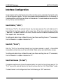
Interface Configuration
All parameters that control the behavior of the interface can be selected in the fourth sector
of the configuration register. The four send modes described below define the behavior of
the balance after switching on or after an interface break. The send mode can be overwritten
at any time by send commands.
Send Stable (“S.Stb”)
After the key “Print” or the external transfer key has been pressed, the next stable result is
transmitted. A brief beep sounds at the same time. If the fully automatic door function
(“doorAuto”) has been selected in the menu, the draft shield first closes automatically and
then reopens after transmission.
To distinguish data strings initiated this way from those resulting from an “S” command,
the first character is a space instead of an “S”.
Send All (“S.ALL”)
After the “Print” or the external transfer key has been pressed, a result is transmitted
immediately without closure of the draft shield. Stable values are identified by a beep.
To distinguish data strings initiated this way from those resulting from an “SI” command,
the first character is a space instead of an “S”.
Send Continuous (“S.Cont”)
The balance continuously transmits approximately two and a half results per second . The
“Print” key and the external transfer key have the same effect as in the “Send Stable” mode.
The data format is not distinguished from that following an “SIR” command.
70
METTLER TOLEDO
AT/MT/UMT Balances
Send Automatic (“S.Auto”)
After every weight change of at least 0.01 g the balance automatically transmits the next
stable result. A brief beep sounds at the same time. The “Print” key and the external transfer
key have the same effect as in the “Send Stable” mode.
The data format is not distinguished from that following an “SNR” command.
Baud Rate
The AT/MT/UMT balance can work with any of the following baud rates:
150, 300, 600, 1200, 2400, 4800, 9600 baud
In all cases, even at very low baud rates and with continuous result transmission, only the
most recent values are sent. There is no storing of “old” results.
Parity
A parity bit may be appended automatically to each character (7 data bits) before
transmission. The parity bit of the received characters is checked. If it does not match the
expected value, the entire message (up to the next line end) is considered invalid. This
causes the balance to send the error message ET. Not affected by the parity check are the
handshake characters SYN, ACK, XON and XOFF. This reduces the risk that the data
exchange between balance and peripheral device is broken due to “lost” (i.e. unrecognized)
handshake characters.
71
AT/MT/UMT Balances
METTLER TOLEDO
The possible parity settings are:
even:
The parity bit is selected such that the sum of all 1 bits (data word
plus parity) is even.
odd:
The parity bit is selected such that the sum of all 1 bits (data word
plus parity) is odd.
off (mark):
The parity bit is always set to 1. On receipt it is not tested. For the
receiver this data format has the same effect as “no parity, two stop
bits”.
space:
The parity bit is always cleared (0). On receipt it is not tested.
Handshake
Many peripheral devices are not capable of processing a continuous data flow, particularly
at high baud rates. Likewise, the balance can also not receive and execute commands at
just any speed. A handshake protocol is generally used to ensure an orderly data flow.
In addition to the proven METTLER TOLEDO CL handshake the AT/MT/UMT is equipped with
the industry-standard protocols CTS/DTR (hardware) and XON/XOFF (software). For
devices without any handshake possibility, the AT/MT/UMT balance can be instructed to
insert a pause at the end of every line.
The possible handshake settings are:
hard (CTS/DTR):
The attached device can stop the data flow from the balance at any
time by deasserting the DTR line (negative voltage on the line). Most
printers can handle this type of handshake. On the other hand, the
balance informs the device that it can not currently receive more data
by deasserting the CTS line.
72
METTLER TOLEDO
AT/MT/UMT Balances
soft (XON/XOFF):
This method requires a simple bidirectional data line; no control lines
are necessary. Both balance and peripheral device can stop the
incoming data flow at any time by sending the character XOFF (ASCII
19, control-S). The character XON (ASCII 17, control-Q) reenables
the communication. Many printers as well as most computers can
operate with this method (the IBM PC only after suitable programming).
Pause:
This setting is provided for devices that are not prepared to handle any
kind of handshake. At the end of each line the balance inserts a pause
of one second before it starts transmitting the next line. Almost any
device can thus be attached to the METTLER TOLEDO AT/MT/UMT if
it is capable of receiving at least one line at a given baud rate, store
it temporarily, and process it within the pause time.
CL:
This is METTLER TOLEDO’s own protocol and was developed particularly with current loop operation in mind. Like XON/XOFF it is a
software-only handshake. The control characters used are SYN
(ASCII 22, control-V) and ACK (ASCII 06, control-F). A special feature
of instruments with CL capability is that after switched on, they
attempt to set up handshake operation in the transmitting and
receiving directions separately. If this fails – possibly because one of
the devices cannot handle the CL handshake protocol – no control
characters appear on the data lines later on. Another feature of CL is
that it operates on whole blocks (lines) of data and not individual
characters as do the other methods. Short-form instructions for
programmers regarding the use of the CL handshake are included in
this manual.
73
AT/MT/UMT Balances
METTLER TOLEDO
End-of-Line (“EOL”)
Messages sent by the balance are normally terminated by the character sequence CRLF
(Carriage Return and Line Feed). Commands are executed only after receipt of the same
sequence. Most computer languages regard the character CR alone as end-of-line,
however. This might lead to inconvenient programming caused by the necessity of having
to strip the line feed character from the beginning of data strings, for example.
The EOL parameter of the AT/MT/UMT balance solves this problem by optionally allowing
the suppression of the line feed. At the same time, a command is executed as soon as CR
is received. This mode is recommended whenever the balance is to be controlled by a
computer program.
The CL handshake depends on the existence of the line feed; the end-of-line option is
suppressed in this case.
74
METTLER TOLEDO
AT/MT/UMT Balances
The RS-232 Interface
This section describes the electrical features of the RS-232 interface and provides tips on
how to use it.
RS-232 is without a doubt one of the most widely used interfaces in the world of data
communication. Despite its great popularity, it is also the cause of much trouble and
frustration. The possible causes of most problems may be summarized in a surprisingly
short list:
• plugs don’t match
• handshake lines either don’t work or stop all data flow
• only garbled characters are received
• transmitted data does not appear at the other end of the cable
The ABC of RS-232
This section illustrates a few basic concepts of the RS-232 data transmission. If your prior
attempts to master RS-232 have been successful, you may safely skip the following section.
Many users are not aware that with RS-232 connections, as with the cables of the mains
power system, a distinction must be made between connectors and receptacles (somewhat
frivolously referred to as male and female plugs). If data leaves a device at pin 2 then it must
enter the partner device at the same pin. This way a simple wiring scheme is possible,
namely pin 1 to pin 1, pin 2 to pin 2, etc. In the RS-232 world, devices with male connectors
are called DTE (Data Terminal Equipment), whereas devices with female connectors are
known as DCE (Data Communication Equipment).
The cabling problem would not exist if all manufacturers would stick to these rules. As in
the well-behaved world of the 110 Volt cable, where safety against electrical shocks is
paramount, each cable would have a male connector at one end and a female connector
at the other. In reality, however, one might encounter data terminals with female and
computers with male plugs (sometimes even correctly so, as they behave like a terminal).
In such cases it is no longer possible to set up a working installation by just providing the
matching cables.
75
AT/MT/UMT Balances
METTLER TOLEDO
A further reason for confusion lies in the naming conventions of the interface lines. For
instance, line 2 is called “Transmitted Data”. But this is only correct when seen from the side
of the DTE. A DCE actually receives data on the Transmitted Data line.
Handshake lines are a particularly rich source of problems. The most frequent symptoms
are the lack of any communication in one or both directions, or the overflowing of the devices
with data, resulting in loss of characters. The cause is usually found in open (i.e.
unconnected) handshake lines. Most devices read this as “handshake deasserted” and
inhibit the data output. A well-known example is the asynchronous serial adapter of the IBM
PC. Some devices, such as the AT/MT/UMT balances, treat an unused handshake input line
as asserted (signifying “OK to send”).
Garbled characters are usually a consequence of mismatched interface parameters such
as baud rate, parity, number of data bits and are therefore not a problem specific to RS-232.
If transmitted data does not appear anywhere, chances are that a device has been
connected to another of the same kind (DCE to DCE or DTE to DTE) without wire crossing.
Imagine message characters travelling down the cable in opposing directions crash into
each other, resulting in mutual annihilation...A less dramatic reason might simply be the
fact that the cable is not plugged in, or has fallen off, or is broken.
76
METTLER TOLEDO
AT/MT/UMT Balances
The RS-232 Connection of the AT/MT/UMT
The balance is wired as a DCE device. The most common application, namely connecting
an RS-232 printer to the balance, should therefore pose no problems. Connection to another
DCE device (computer, modem, etc.) requires that the data and handshake lines be
crossed. Such cables are sometimes referred to as “null modem” and are available from
many sources. In addition, so-called “intelligent” cables exist that perform the necessary
crossings automatically whenever they detect a conflict.
The factory setting of the handshake is “Pause”. This ensures that a printer without
handshake works right away in most cases. If a computer or a video terminal is attached,
selecting one of the other handshake methods is recommended as the delay time between
the messages is quite noticeable.
The diagrams in the section “The DATA I/O Connector” show some typical cabling
suggestions. It should be noted that it is normally up to the computer program to deal with
the handshake lines. It is entirely possible that simpler configurations than those shown
work without problems.
77
AT/MT/UMT Balances
METTLER TOLEDO
The METTLER TOLEDO CL Interface
This section describes the electrical features of the CL interface.
The interface operates with a constant current of 20 mA. It must be supplied by an external
current source, one each for the transmitting and receiving loop (see illustration).
The best results are obtained when the following technical limits are observed:
Voltage compliance of source: 15V (+10%, -0%)
Current range: 18...24 mA
Rise/fall time: 2...20 mA/µs
Cable: shielded, twisted pair, ca. 125 /km or less, conductor cr oss-section 0.14 mm2 or
larger, capacitance 130 nF/km or less
Max. length: 1000 m at 300 baud, 500 m at 2400 baud.
The CL interface section of the balance is based on two independent passive transmission
loops:
passive
passiv
aktiv
active
Balance
Computer
The passive current loops of the balance must be conntected to external current sources.
To avoid destruction of the CL interface by these sources, it is essential to observe the
following limiting data:
I
(mA )
I max 30 mA
U max 40V
P max 800 mW
U
40 ( V )
The U/I characteristic of the source must lie within the hatched area.
78
METTLER TOLEDO
AT/MT/UMT Balances
CL for Programmers
This method has the quite undeserved reputation of being complicated and only suitable
for current loop connections. It owes its apparent complexity mainly to the sophisticated
procedure used to set up the handshake, and the rigid distinction between text characters,
termination characters, and code extensions (ESC sequences). In practice, however,
simplifications can usually be applied (e.g. it can be assumed that the termination character
is always a line feed). Since the CL handshake protocol offers advantages in many
applications – like the feature where complete messages can be requested from the balance
individually, or the absence of unwanted control characters when handshake is not
established – a few tips will be given here to facilitate working with this protocol.
Initialization
The balance attempts to establish handshake operation not only after it is switched on, but
also after every break in the data line (disconnecting and connecting the cable, receipt of
a break from the peripheral device, switching on the peripheral device), and also after
selecting the CL mode in the configuration register. About 200 ms after the electrical
connections have been established, your device will receive the SYN character (Synchronous
Idle, ASCII 22, Control-V). The procedure that follows now depends on whether you wish
simply to slow down the balance’s transmissions using handshake signals, or whether the
balance also should report its readiness to receive commands.
Device-controlled Balance Output
Send the character ACK (Acknowledge, ASCII 06, control-F) to the balance. It will then
respond with exactly one data block, if available. Each additional ACK authorizes the
balance to send another message. Do not send more than one ACK before receiving a data
string; the balance will not store them.
79
AT/MT/UMT Balances
METTLER TOLEDO
Balance-controlled Device Output
Transmit the character SYN to the balance to inform it that your device understands the CL
handshake. The balance responds by echoing the SYN character, indicating that it is now
set up for CL handshake. From now on do not send commands to the balance unless you
have received an ACK.
Bidirectional Handshake
Ideally, your device can recognize the end of the break condition. Wait about 200 ms to let
the signals settle and then send the SYN character.
If break recognition is not possible, make sure that the interface of your device is fully
operational within 200 ms after the balance is turned on. Do not send SYN.
In both cases, you will receive the inquiry signal SYN from the balance. Confirm receipt of
the character and awareness of the CL handshake mode by sending SYN. As soon as you
are ready to receive balance messages, send an ACK. From now on two rules apply:
1. Do not send a command to the balance unless you have received an ACK.
2. Send exactly one ACK whenever you are ready to receive a data block from the
balance.
The state of the CL handshake mode may be checked on the balance display: If the
handshake is set up in both directions, the symbol I/O is permanently on,otherwise it blinks.
The I/O symbol is not shown at all if a break is detected on the input data line.
Once handshake has been set up, it can be cancelled only by switching off the instruments,
by an interface break, or by changing the handshake mode in the configuration register.
80
METTLER TOLEDO
AT/MT/UMT Balances
The DATA I/O Connector
This connector at the rear of the balance is used for attaching peripheral devices with a serial
interface, either for RS-232 or CL operation. Ordering information for suitable plugs and
cables can be found in the brochure Technical specifications and accessories. This
publication also contains tips on the correct setting of several general-purpose printers, as
well as a list of the separately available Engineering Support Bulletins describing the
connection of METTLER TOLEDO balances to a number of popular personal computers.
Connecting a Personal Computer
The Engineering Support Bulletins mentioned above describe the simplest case of
connecting a balance to a computer, which is by not taking advantage of the handshake
lines. If the additional capabilities offered by the AT/MT/UMT balance are to be used, the
wiring diagrams below may serve as a guide.
Examples:
IBM-PC, PC/XT and compatibles
PC (DTE)
Balance (DCE)
TxD
2
2
Data In
RxD
3
12
Data Out
RTS
4
CTS
5
4
Handshake Out
DSR
6
GND
7
13
GND
DCD
8
3
Handshake In
DTR 20
Mini-Mettler
(15-pinl)
DB-25 (male)
Appropriate cable: 210491
81
AT/MT/UMT Balances
METTLER TOLEDO
IBM-PC/AT and compatibles
PC/AT (DTE)
Balance (DCE)
TxD
3
2
Data In
RxD
2
12
Data Out
CTS
8
4
Handshake Out
GND
5
13
GND
RTS
7
DSR
6
DCD
1
DTR
4
3
Handshake In
Mini-Mettler
(15-pin)
DB-9 (male)
Appropriate cable: 210493
Apple Macintosh Plus, SE, SE/30 and Macintosh II, IIx, IIcx
Mac Plus, SE, II
TxD-
Balance (DCE)
2
Data In
RxD- 3
12
Data Out
4
13
GND
GND
5
RxD+ 6
DTR
2
3
Handshake In
HSK
1
4
Handshake Out
Mini-Mettler
(15-pin)
Mini DIN-8
Appropriate cable: 210495
82
METTLER TOLEDO
AT/MT/UMT Balances
The GT Connector
All METTLER TOLEDO GT devices are attached to the AT/MT/UMT balance using this
connector. In addition, certain devices of the GM series can be connected by use of the
GM/GT adapter (210498) (see brochure Technical specifications and accessories of the
AT/MT/UMT balance). The connectors are T-shaped so that several devices can be operated
at the same time.
83
AT/MT/UMT Balances
METTLER TOLEDO
The Re-Zero Connector
Remote control of the functions “Open/close Doors”, “Print/Transfer” and “Tare” without
using the serial interface is made possible by this connector. Since signals indicating the
status of the doors (open, closed or in-between) are also available, a small laboratory
automation system can be set up easily. For such purposes METTLER TOLEDO offers a
control cable (210494) with loose ends. The documentation enclosed with the cable
shows the pin assignments of the lines and provides application tips.
The remote control functions may be disabled or enabled individually by the RX command.
A Twin Foot Switch (210580) is also available as an accessory. It allows the triggering of
a data transfer operation as well as taring by pressing the appropriate foot switch. This way,
hands remain free for loading the scale and other tasks. This, when used together with the
automatic door closing operation (“doorAuto”), provides an unusually high degree of
convenience.
RE-ZERO
6
1
11
7
12
2
8
Code
1/2
3
13
9
14
4
10
5
15
84
METTLER TOLEDO
AT/MT/UMT Balances
Data Format
Weighing result strings are formatted as follows:
1
2
3
4
5
6
ID
7
8
9
10
11
12
13
14
15
16
17
UNIT
DATA
18
19
CR
20
LF
where:
ID
DATA
UNIT
hatched
CR, LF
Identification
Weighing result
Weight unit
Space (ASCII 32)
Carriage Return, Line Feed
The identification ID denotes the type of communication:
The first character is a
Space if the weighing result has been triggered by the “Print” key or the foot switch.
S
if the weighing result has been requested by an “S” command or the
balance is in the Send Continuous mode (“S.Cont”).
The second character is a
Space if the weighing result is stable
D
if the weighing result is unstable (“dynamic”).
The weighing result appears right-justified in the DATA field. If the value is negative, the sign
is placed immediately in front of the first digit. Leading zeros are not shown except for the
zero to the left of the decimal point. The position of the decimal point depends on the balance
model and the selected weight unit. In the coarse range of the balance, position 13 always
contains a space. Whenever DeltaDisplay is active, the last result digit is replaced by a
space.
85
AT/MT/UMT Balances
METTLER TOLEDO
The weight unit appears left-justified in the UNIT field. The number of characters used is
determined by the length of the unit string, up to four characters.
The message is terminated by Carriage Return and Line Feed, immediately following the
weight unit. If “EOL cr” has been selected in the configuration register, Line Feed is
suppressed.
If, for some reasons, the balance cannot transmit a valid result (e.g. on an over-/underload
condition, or when waiting for stability), only the identification block with the character “I”
in the second position appears. In the case of overload, an additional “+” is appended, for
underload a “–”.
Examples:
SI
Invalid result after “S” command or in the “Send Continuous” mode
SI-
As above, but additionally identified as underload
I+
Overload; data transmission triggered by “Print” key or external
transfer switch (note the space in the first position)
86
METTLER TOLEDO
AT/MT/UMT Balances
7-Segment Representation of Text
The “D” command allows the display of any kind of text on the balance, restricted only by
its capability to represent characters using only seven segments. The following table shows
the 95 printable characters of the ASCII character set (ISO-646) and how they appear on
the AT/MT/UMT balance.
K
'.
w
õ
ú
`ê
ëè
'
[
]
°
.
-
.
ê
-é
SP
!
"
#
$
%
&
'
(
)
*
•
,
-
.
/
0
1
2
3
4
5
6
7
8
9
û
ê
c
≠
c
2
ø
1
2
3
4
5
6
7
8
9
:
;
<
=
>
?
c
A
B
C
D
E
F
G
H
I
J
K
L
M
N
O
@
A
B
C
D
E
F
G
H
I
J
K
L
M
N
O
P
Q
R
S
T
U
V
W
X
Y
Z
ò
4
ô
m
_
P
Q
R
S
T
U
V
W
X
Y
Z
[
\
]
`
_
`
a
b
c
d
e
f
g
h
i
j
k
l
m
n
o
`
a
b
c
d
e
f
g
h
i
j
k
l
m
n
o
P
q
r
s
t
u
v
w
x
y
z
ñ
l
ó
å
p
q
r
s
t
u
v
w
x
y
z
{
|
}
~
87
AT/MT/UMT Balances
METTLER TOLEDO
What if...
Murphy’sLaw states that“ if anything can go wrong, it will go wrong”. This applies
particularly to the situation where devices of different manufacturers have to be interconnected. The following tips are meant to help put you on the right track to the solution of your
problems more quickly.
The messages of the balance are too short/too long and completely unintelligible.
The baud rates of balance and peripheral device do not match.
The messages of the balance are almost correct, but some characters are garbled.
The parity settings do not match.
The messages of the balance appear error-free on the peripheral device, but most
commands are answered with “ET”.
This is also a parity problem. Many peripheral devices simply ignore the parity bit
and show the characters correctly in all cases. The AT/MT/UMT responds to
commands containing characters with wrong parity with the error message “ET”, but
only if parity “even” or “odd” has been configured.
The messages of the balance appear at a very slow rate (about one per second), no matter
what the baud rate.
The AT/MT/UMT is running in the handshake mode “Pause”, which is intended for
printers without handshake facilities. Since this is the factory setting, you should
select another mode when working with high-speed peripherals.
The printer remains silent although all settings and connections are correct.
Printers are frequently equipped with a unidirectional interface, i.e. the data line in
the balance direction is inoperative. This is recognized by the AT/MT/UMT as a break,
resulting in the balance not transmitting if CL handshake mode is configured.
Solution: Configure a different handshake mode. (CL handshake wouldn’t make
sense in a unidirectional environment, anyway).
88
METTLER TOLEDO
AT/MT/UMT Balances
Many printers have a ready key (labeled “Online”, “Ready”, “Select” or something
similar). Pressing this key ensures that the printer is ready to receive. An indicator
lamp sometimes helps you verify this mode.
The computer recognizes the first weighing result without problem, but subsequent results
lead to errors.
Most computer languages treat the character Carriage Return (CR) as an end-of-line
indication, not the Line Feed (LF) as is standard with Mettler balances. Therefore, the
LF will appear as the first character of the next message. Solution: Select “EOL cr” in
the configuration register. Remember that this implies that commands sent to the
balance are terminated with CR, too, not CRLF. “EOL cr” is not available in the
handshake mode “CL”.
Messages received from the balance are OK, but all commands are ignored.
Cabling problems apart, the cause may be that your computer terminates commands
with Carriage Return. With the balance expecting a Line Feed, it will never begin to
interpret your command. Solution: Select “EOL cr” in the configuration register. Note
that the Line Feed will then be stripped from the balance messages, too.
The I/O symbol does not appear in the display although a peripheral device is attached.
The peripheral device is probably still keeping the data input line of the balance in
the break condition. Also, check for broken wires and loose connectors.
The I/O symbol flashes.
The handshake mode is set to “CL” but fully bidirectional handshake has not yet been
set up.
Every command sent to the balance produces an “EL” error message.
The balance is in the “Off” condition as a result of a power interruption. The only
command it will accept is “T”, which will restore normal operation.
89
AT/MT/UMT Balances
METTLER TOLEDO
The symbol REMOTE is lit and can’t be removed.
This symbol appears whenever one or more front-panel keys have been disabled by
an interface command. Possible commands are: R1, RK or WI D. Try sending R0
or RK without parameter. If the symbol still appears, the door keys have been inhibited
by WI D or WI DF. Send WI E to reenable the door keys. The REMOTE symbol should
be off now.
90
METTLER TOLEDO
AT/MT/UMT Balances
1st Aid Kit
Finally, a few helpful tips taken from seemingly hopeless real-life situations:
1. Make sure that the physical cable connections are in order. This is very important. The
best software can’t help you fix a broken or misconnected wire. The wiring diagrams
shown earlier may be useful here.
2. Configure the balance as follows:
Send Mode:
Baud rate:
Parity:
Handshake:
EOL:
Send Continuous (“S.Cont”)
same as peripheral device (extremely important!)
same as peripheral device (ignore if unknown))
off
CRLF
3. The balance now transmits results continuously. If you still don’t get any data, chances
are that the peripheral device is inhibiting itself because of open handshake lines.
Consider connecting handshake inputs with asserted outputs (see page 81 for an
example). Solve this problem before proceeding.
4. Data transfer from the balance to the peripheral is now almost up and running. Don’t
worry if some of the messages appear garbled; this is due to the balance operating
without handshake.
5. Send the four characters S,I, Carriage Return and Line Feed to the balance. If your
device does not have a Line Feed key, use Control-J.
91
AT/MT/UMT Balances
METTLER TOLEDO
6. The balance now transmits…
…nothing anymore:
The command SI has been accepted, causing the Send
Continuous mode to end. Congratulate yourself and advance
to step 7.
…ET:
Excellent. The connection is in order, only the parity settings
are not matched yet.
…results as before:
The balance has not recognized the command. Change the
parity setting of the balance and try again. Set the EOL
parameter to CR and send the command without Line Feed.
If nothing helps (and you feel sure you have really followed
the directions in step 1), then it looks very much like a
handshake problem as described in step 3. If still unsuccess
ful, get yourself a cup of coffee, lean back and think it all over.
7. Communication is now working in both directions. If the balance responds to
commands with ET, the parity settings are still different. The correct setting of the
handshake mode is usually important only if you wish to use the Send Continuous mode
of the balance, or if you wish to send commands to the balance as quickly as possible.
In the latter case the echo mode (EC 1) might come in handy, too.
92
METTLER TOLEDO
AT/MT/UMT Balances
Glossary
ACK — Short for acknowledge. A control character of the ASCII character set having the
value 06 (hexadecimal). It is used in the METTLER TOLEDO CL handshake protocol to tell
other device that it may send exactly one line of data.
ASCII — American Standard Code for Information Interchange. This ubiquitous standard
defines how printable and control characters are encoded into 7 bits. For example, any
device that speaks ASCII will interpret the code 41 (hexadecimal) as an uppercase “A”.
Asynchronous — Most data transmission between personal computers and instruments
like the AT/MT/UMT occurs asynchronously, meaning that each character is individually
synchronized, usually by using a start bit and a stop bit. The duration of the individual bits
is defined by the baud rate.
Balance settings — The condition a balance is in at a given moment, based on the
currently valid configuration and the menu settings.
Baud — Strictly speaking, baud is the number of changes in signal levels, frequency,
or phase per second on a communication channel. If each change represents one bit of
data, as is the case with the AT/MT/UMT, baud is the same as bits per second. However,
it is possible for one signal change (one baud) to equal more than one bit of data. By default,
the AT/MT/UMT transmits 2400 bits per second, so its baud rate is 2400 baud.
Bit — The smallest unit of data. Represented by a 1 or a 0.
Break — The condition where the data line remains in the spacing state for longer than
the duration of a character.
Character — A letter, number, or special symbol (such as a comma or percent sign)
contained in data or used to control communication devices.
CL — Current Loop. 1) An alternative to RS-232 using constant current (20 mA) instead
of voltage. It is much less common and has no standard connector. Its main advantage is
that it can cover larger distances. 2) The name of a handshake protocol used by
METTLER TOLEODO.
Computer — A device, usually in a box, consisting of a Central Processing Unit (CPU),
memory and connections to the outside world (ports). Programs, called software, allow it
to make errors much faster than a human being.
93
AT/MT/UMT Balances
METTLER TOLEDO
Configuration register — A set of menus and menu items on the AT/MT/UMT which allow
the user to configure the balance for his particular application.
Control character — A character of the ASCII character set which does not print, but may
be used to control communication devices. Examples: Carriage Return, ACK, XOFF.
CR — Carriage Return. A control character of the ASCII character set (0D hexadecimal).
Originally used to cause a printing device to move its print head to the left margin, it now
generally signifies the end of a line or a command.
CTS — Clear-to-Send. One of the signals defined by the RS-232 standard. It is sent by
the DCE on pin 5 of the standard 25-pin connector. It is an indication to the data terminal
equipment (the peripheral connected to the balance) whether the DCE can accept data on
the Transmit Data line or not.
Current Loop — see CL.
DCE — Data Communication Equipment. One side of a RS-232 setup. It must be linked
to a DTE. Transmits data on pin 3 of the standard RS-232 connector.
DTE — Data Terminal Equipment. One side of a RS-232 setup. It must be connected to
a DCE. Transmits data on pin 2 of the standard RS-232 connector.
DTR — Data Terminal Ready. One of the signals defined by the RS-232 standard. It is
sent by the DTE on pin 20 of the standard 25-pin connector as an indication to the balance
whether the DTE can accept data on the Received Data line or not.
EAROM — Electrically Alterable Read-Only Memory. An electronic memory device that
may be read or written to. Its main characteristic is its ability to keep the stored data even
if power is removed. It is used in the AT/MT/UMT balances to store user settings, calibration
data and many more items.
ESC — Escape. A control character of the ASCII character set (1B hexadecimal). Has
many uses, e.g. exiting from a mode or operation, starting a special character sequence
and more.
Handshake — A method designed to synchronize data flow between devices. May be
realized using special characters (see XON, XOFF) or dedicated hardware lines (see CTS,
DTR). Handshaking may also occur when your boss has verified that your new weighing
system is up and running.
94
METTLER TOLEDO
AT/MT/UMT Balances
Hexadecimal — A number system based on 16 numbers instead of the common 10.
This allows the easy expression of 4-bit entities. The numbers used are 0…9, then A for
10, B for 11 and so on up to F for 15.
LAN — Local Area Network. A system of several devices (usually more than two)
connected via a common cable, capable of talking to each other using a defined set of
protocols. Normally not associated with RS-232 setups.
Leading zeros — Zero digits shown to the left of the integer part of a number, where they
are not really necessary. Example: 000123 instead of 123. Sometimes used in critical
balance applications where it is important to distinguish between digits turned off because
they are leading zeros and digits not shown because of a hardware malfunction.
LF — Line Feed. A control character of the ASCII character set (0A hexadecimal). Causes
a printing device to move its print head one line down. It may also mark the end of a message
or a command.
mark — Indicates the presence of a data signal on a communication line (current flowing
in current loop or voltage negative in RS-232). The idle state of a connection is mark.
Menu — With the AT/MT/UMT balances, pressing the key labelled “Menu” leads the user
to a number of menu items allowing him to change the behavior of the balance with respect
to the environment. Also found in the menu are the calibration and the reference weight
defining part of the built-in applications piece and percent weighing.
mnemonic — Abbreviations designed to help your memory. If you can remember this
word you probably don’t need mnemonics.
Modem — A device which converts bit-serial communication signals to signals
compatible with the phone system, thus extending a serial data link almost indefinitely. This
is the prime example of a DCE device.
Parity — The number of all bits set to 1 in a sequence of bits. Depending on the mode
chosen, a “1” is added to the sequence if the sum is even or odd, a “0” otherwise. Using
the same algorithm, the receiving device may detect transmission errors that change an odd
number of bits in the sequence.
Protocol — A specification that describes the rules and procedures that products should
follow to perform activities on a data link, such as transmitting data. Protocols allow
products from different vendors to communicate.
95
AT/MT/UMT Balances
METTLER TOLEDO
RS-232 — A standard introduced in 1962 by the EIA (Electronic Industries Association)
describing the “Interface Between Data Terminal Equipment and Data Communication
Equipment Employing Serial Binary Data Interchange”. It covers the mechanical as well as
the electrical characteristics of the interface. The latest revision, EIA-232-D (1986), is
closely related to the CCITT V.24 specification.
Serial communication — A method for sending data from one place to another where
the information is split up into single electrical bits, which are sent out one after another.
Obviously, this takes more time than sending chunks of bits - each chunk representing a
character, for example - simultaneously. The main advantage of serial communication is
that it requires only a single wire in each direction.
space — Indicates the absence of a data signal on a communication line (no current
flowing in current loop or voltage positive in RS-232).
Space (Blank) — The first printable character of the ASCII character set. Although it’s
called printable, it doesn’t put any ink on the paper (or electrons on the video screen).
Rather, it advances the print head by the space usually occupied by a character.
String — A sequence of characters. In computer parlance, a word is a certain number
of bits, so a word is not called a word but a string. (Who said computers make life easier?)
SYN — Synchronous Idle. A control character of the ASCII character set having the value
16 (hexadecimal). It is used in the METTLER TOLEDO CL handshake protocol to tell other
devices that CL handshake is available.
Terminal — Any device that can send and/or receive data via a communication line.
Normally a box with a video screen and a keyboard, but also a personal computer running
a terminal emulation program.
XOFF — Also DC3 (Device Control 3). A control character of the ASCII character set
having the value 13 (hexadecimal). It is used in the METTLER TOLEDO handshake mode
“soft” to inhibit the other device from sending data.
XON — Also DC1 (Device Control 1). A control character of the ASCII character set having
the value 11 (hexadecimal). It is used in the METTLER TOLEDO handshake mode “soft” to
authorize the other device to resume sending data after it has been stopped by a XOFF
character.
96
Leerseite
To protect your METTLER TOLEDO product’s future:
METTLER TOLEDO Service assures the quality, measuring
accuracy and preservation of value of all METTLER TOLEDO
products for years to come.
Please send for full details about our attractive terms of
service.
Thank you.
*P704018*
Subject to technical changes and to the availability
of the accessories supplied with the instruments.
© Mettler-Toledo AG 2006
704018B Printed in Switzerland 0612/2.12
Mettler-Toledo AG, Laboratory & Weighing Technologies, CH-8606 Greifensee, Switzerland
Phone +41-1-944 22 11, Fax +41-1-944 30 60, Internet: http://www.mt.com