1
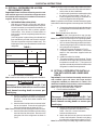
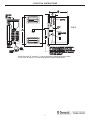
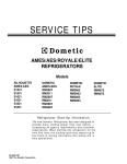
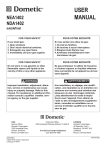
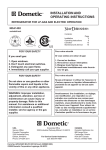
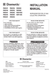
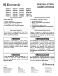
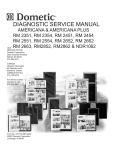
3108705.744 INSTRUCTIONS
USA
SERVICE OFFICE
Dometic Corp.
509 So. Poplar St.
LaGrange, IN 46761
(260) 463-4858
POWER VENTILATOR ASSEMBLY
PART NO. 3108705.744
For Two Door Absorption Refrigerators
CANADA
Dometic Dist.
866 Langs Dr.
Cambridge, Ontario
CANADA N3H 2N7
(519) 653-4390
PATENT NO. 5355693
For Service Center
Assistance Call:
800-544-4881
INSTALLATION
INSTRUCTIONS
Form No. 3309090.003 3/04
(French 3309091.001)
©2004 Dometic Corporation
LaGrange, IN 46761
1
Power
Ventilator Asm.
3108705.744
3108705.744 INSTRUCTIONS
SAFETY INSTRUCTIONS
! WARNING
These instructions must be read and understood before installation of this kit. This kit
must be installed by a Dometic Service Center or a qualified service technician. Modification of this product can be extremely hazardous and could result in personal injury or
property damage.
This manual has safety information and instructions to help users eliminate or reduce the risk of
accidents and injuries.
RECOGNIZE SAFETY INFORMATION
!
PURPOSE:
This Power Ventilator Assembly is for Dometic's six (6) cubic
foot or larger refrigerators with multiple venting applications.
Its purpose is to assist required air movement across the
refrigerator condenser to ensure optimum performance.
Note: Install the ventilator switch after power ventilator
assembly installation.
This is the safety-alert symbol. When you see this
symbol in this manual, be alert to the potential for
personal injury.
This Assembly Contains:
Follow recommended precautions and safe operating instructions.
UNDERSTAND SIGNAL WORDS
A signal word , WARNING OR CAUTION is used
with the safety-alert symbol. They give the level of
risk for potential injury.
(Qty)
(Part No.)
(1)
(1)
(2)
(1)
(1)
(1)
(2)
(1)
(1)
(2)
3107930.004
3104133.016
3108706.858
3105432.003
3105432.011
315503.005
3108710.033
3309090.03
3105433.019
312096.001
(Description)
Ventilator fan, 12V DC
Fan Limit Switch, 12V DC
Screw, #8x3/8 Drill Point
Mounting Bracket, RH
Mounting Bracket, LH
Fuse Holder and Fuse (1 amp)
Screws, #8 x 2"
Installation Instructions
Wiring Diagram Decal
Screws, 10-16 x .38
Parts Supplied by Installer: (Through-the-Floor)
(1)
(1)
! WARNING indicates a potentially hazard-
Varmit Screen
Fabricated Duct Extension
GENERAL INSTRUCTIONS:
These instructions are supplemental to the refrigerator installation instructions.
ous situation which, if not avoided, could result in
death or serious injury.
Important:
! CAUTION indicates a potentially hazard-
ous situation which, if not avoided may result in
minor or moderate injury.
CAUTION
used without the safety alert
symbol indicates, a potentially hazardous situation which, if not avoided may result in property
damage.
Read and follow all safety information and instructions.
2
The Power Ventilator Assembly must be used with
certified upper and lower side vents.
Install refrigerator in accordance with the installation instructions supplied with the refrigerator.
Follow the N.E.C., state and local code requirements referenced in the product installation instructions.
Comply with the compartment sealing instructions
indicated in the instructions packet.
3108705.744 INSTRUCTIONS
Select the option which suits your specific application.
Follow Power Ventilator Assembly instructions for that
specific application.
OPTION 1: Through-The-Floor Vent Installation with
Upper Roof Vent
OPTION 2: Upper and Lower Plastic Side Vents
OPTION 3: Side-By-Side Refrigerator with Upper and
Lower Plastic Side Vents
OPTION 1: Through-The-Floor Vent Installation with Upper Roof Vent
FIG. 1
ROUTE WIRING TO
THIS AREA & SECURE
MOUNT FAN LIMIT SWITCH ON RIGHT SIDE
OF CONDENSER EXCEPT THESE MODELS:
NDR1292, NDR1492, NDA1402, NDE1402,
NDE1402 & NEA1402
LOCATE FAN LIMIT SWITCH LEFT
SECURE SWITCH
SIDE OF REFRIGERATOR
WITH #8x3/8” SELF
DRILLING SCREWS
Closes 150oF/Opens 130oF
FAN LIMIT
SWITCH
(Close on
Temp. Rise)
2”
RED WIRE
FUSE
1 AMP.
FAN
RED
WIRE
COIL
+ o
-10
FIG. 1A
TERMINAL J3 ON
REFRIGERATOR
POWER MODULE
(12 VDC +)
REFRIGERATOR
FRAME GROUND
TERMINAL
FAN LIMIT
SWITCH
RED WIRE
ROUTE TO
POSITIVE TERMINAL
ON REFRIGERATOR
FAN PREASSEMBLY
AREA
Temporarily
Locate fan in
this area
before final
installation
into cabinet
FAN
BLUE
WIRE
MOTOR
FIG. 1B
12 volts +
DC
12 volts
DC
+
-
Min. depth of
duct is 4"
Max. depth of
duct is 54"
MIN. 3"
MAX. 8"
Min. duct depth 4"
Max. duct depth 54"
FUSED RED WIRE
ROUTED TO
TERMINAL J3 ON
POWER MODULE
(POSITIVE)
11" Min.
20" Max.
Min. 3"
Max. 8"
1-1/2" Typ.
#8X2.0”
Screws (2)
BLOWER
-Route blue wire to
frame ground terminal on
refrigerator
-Route red wire to limit
switch
Ventilator
3105432.003 &
3105432.011
Mounting
Brackets
6-1/2"
4"
Min.
DUCT
EXTENSION
4" ± 1"
MIN. 70 SQ. IN.
TOTAL AREA
AIR
FLOW
#10 Fan Mtg.
Bolts
Varmint
Screen
1/4" Mesh Min.
3
3108705.744 INSTRUCTIONS
Note: Route wire away from sharp edges and hot surfaces.
d. Remove the fuse from fuse holder and store in
safe location for later installation.
e. Install mounting brackets to ventilator fan using
the #8 x 2" screws provided. See FIG. 1B.
f. Install refrigerator according to installation instructions supplied with refrigerator.
Note: Completion of the Power Ventilator Assembly installation will be made through the rear access panel. See Table
1.
g. Connect the short red wire (fuse holder base) to
the refrigerator terminal block labeled +12V DC.
See FIG. 1.
Note: Do Not install fuse at this time.
h. Install fan in through-the-floor vent (use predrilled mounting holes) as shown in FIG. 1 & 1B.
Note: Ensure that air flow arrow on fan is pointing upward.
i. Inspect all wiring. Ensure wiring is secure and
will not contact sharp edges and hot surfaces.
j. Attach wiring diagram form kit beside existing
wiring diagram on refrigerator.
k. Install varmit screen as shown in FIG 1B.
l
Complete additional installation instructions
stated in the instructions supplied with the
refrigerator.
m. Install fuse within fuse holder.
n. The power ventilator is now functional. The fan
limit switch will energize the fan when ambient
temperatures exceed 100° F. This system will
operate automatically with the fluctuation of the
refrigerator's condenser temperatures.
A. OPTION 1: REFRIGERATOR ACCESS
REQUIREMENT (REAR)
Important: Power Ventilator Assembly must be used
with certified upper roof vent and the refrigerator must
be installed as directed by the installation instructions
supplied with the refrigerator.
1. REFRIGERATOR ACCESS (REAR)
With the use of this Kit in conjunction with belowfloor ventilation, a sealed access panel is required.
Access is necessary to complete the installation, to
perform gas leak tests, and to perform periodic
maintenance. If the access is located within an
interior wall, it must be completely sealed from the
living space.
If the refrigerator is placed along the sidewall and
floor ventilation is provided, rear access is required.
This door or panel should prevent water entry. The
following are minimum sizes allowed for each series
refrigerator.
TABLE 1
MODEL SERIES
ACCESS PANEL DIMENSION
A
B
RM3662, RM3862,
NDR1062
22"
14"
NDR1292, NDR1492, NDA1402,
NDE1402, NDR1402, NEA1402
36"
16"
A
B
B. OPTION 2: REFRIGERATOR INSTALLATION WITH UPPER AND LOWER SIDE
VENTS
Important: Power Ventilator Assembly must be used
2. Power Ventilator Installation
Note: Install fan limit switch prior to refrigerator installation.
with certified upper and lower side vents and the
refrigerator installed per dimensions in Table 2. For
additional installation information, see the Installation
Instructions supplied with the refrigerator.
Note: Use only on models listed in Table 2.
1. Power Ventilator Installation
! WARNING
Disconnect 115 volt AC and 12 volt DC. Failure to follow these instructions could create a
shock hazard causing death or severe personal injury.
! WARNING
a. Use the (2) #8X3/8" self drilling screws (supplied) to install fan limit switch to refrigerator.
See FIG. 1 for fan limit switch location and
dimensions.
b. Attach red wire from fan motor to one terminal of
the fan limit switch. Route the wire along the
side of the refrigerator as shown in FIG. 1.
Note: Route wire away from sharp edges and hot surfaces.
c. Attach red wire with fuse holder to the remaining
terminal of the fan limit switch. Route the wire
along the side of the refrigerator as shown in
FIG. 1.
Disconnect 115 volt AC and 12 volt DC. Failure to follow these instructions could create a
shock hazard causing death or severe personal injury.
a. Use the (2) #8X3/8" self drilling screws
(supplied) to install fan limit switch to refrigerator. See FIG. 1 for fan limit switch
location and dimensions.
b. Attach red wire from fan motor to one terminal
of fan to the limit switch. Route the wire along
the side of the refrigerator as shown in FIG. 2.
Note: Route wire away from sharp edges and hot surfaces.
4
3108705.744 INSTRUCTIONS
TABLE 2
(Dimensions in Inches)
Model
Min.
Dim.
No.
RM3862
NDR1062
A
61
61
Min.
Dim.
B
24-5/8
24-5/8
Min.
Dim.
Max.
Dim.
C
5-1/8
5-1/8
C
8
8
Max.
Dim.
D*
3-1/2
3-1/2
Max.
Dim.
E
1
1
F
45-1/2
45-1/2
C
Air
Direction
CENTER
OF
REFRIG
FIG. 2
BAFFLE
D*
A
FAN
B
FAN
F
VENTILATOR
FAN
E
12 volts +
DC 12 volts +
DC -
BLUE WIRE
TO GROUND
TERMINAL ON
FRAME
RED WIRE
TO TERMINAL
J3 ON POWER
MODULE
THE FAN PLACEMENT DIMENSION
TO THE REFRIGERATOR FLOOR
MUST BE MAINTAINED EVEN WHEN
UPPER VENT IS LOCATED HIGHER
THAN MIN. DIM. "A"
* When dimension "D" exceeds 1", it may be necessary to add baffle/s above lower
access vent, as shown, for more efficient operation in warm temperatures.
c. Attach red wire with fuse holder to the remaining
terminal of the fan limit switch. Route the wire
long the side of the refrigerator as shown in FIG.
2.
Note: Route wire away from sharp edges and hot surfaces.
d. Remove the fuse from fuse holder and store in
safe location for later installation.
e. Install mounting brackets to ventilator fan using
the #8 x 2" screws provided. See FIG. 1B.
f. Install refrigerator according to installation instructions supplied with refrigerator.
Note: Completion of the Power Ventilator Assembly installation will be made through the rear access panel See Table
2.
g. Connect the short red wire (fuse holder base) to
the refrigerator terminal block labeled +12V DC.
See FIG. 2.
Note: Do Not install fuse at this time.
h. Install fan as shown in FIG. 2.
Note: Ensure that air flow arrow on fan is pointing upward.
i. Inspect all wiring. Ensure wiring is secure and
will not contact sharp edges and hot surfaces.
j. Attach wiring diagram form kit beside wiring
diagram on refrigerator.
k. Complete additional installation instructions
stated in the installation instructions supplied
with the refrigerator.
l. Install fuse within fuse holder.
m. The power ventilator is now functional. The fan
limit switch will energize the fan when ambient
temperatures exceed 100o F. This system will
operate automatically with the fluctuation of the
refrigerator's condenser temperatures.
5
3108705.744 INSTRUCTIONS
e. Attach red wire from fan motor to one terminal of
fan limit switch.
Note: Route wire, as shown in FIG. 3, away from s h a r p
edges and hot surfaces.
f. Attach red wire with fuse holder to the remaining
terminal of fan limit switch. Route the wire along
side of refrigerator as shown in FIG. 3.
Note: Route wire away from sharp edges and hot surfaces.
g. Remove fuse from fuse holder and store in safe
location for later installation.
h. Connect the short red wire (fuse holder base) to
the refrigerator terminal block labeled +12V DC.
See FIG. 3.
Note: Do Not install fuse at this time.
i. Inspect all wiring. Ensure wiring is secure and
will not contact sharp edges and hot surfaces.
j. Complete additional installation instructions
stated in the installation instructions supplied
with the refrigerator.
k. Install fuse within the fuse holder.
l. Attach wiring diagram from kit beside existing
wiring diagram on refrigerator.
m. The power ventilator is now functional. The fan
limit switch will energize the fan when ambient
temperatures exceed 100o F. This system will
operate automatically with the fluctuation of
refrigerator's condenser temperatures.
C. OPTION 3: SIDE-BY-SIDE REFRIGERATORS INSTALLATION WITH UPPER AND
LOWER SIDE VENTS
Important: Power Ventilator Assembly must be used
with certified upper and lower side vents and the
refrigerator installed per dimensions in Table 3. For
additional installation information, see the Installation
Instructions supplied with the refrigerator.
Note: Use Only on Models in Table 3.
1. Power Ventilator Installation
Note: Install fan limit switch prior to refrigerator installation.
See FIG. 1 on Page 3.
a. Use the (2) #8X3/8" self drilling screws (supplied) to install fan limit switch to refrigerator.
See FIG. 1 for fan limit switch location and
dimensions.
b. Install refrigerator according to installation instructions supplied with the refrigerator.
Note: Completion of the Power Ventilator Assembly installation will be made through access panel (lower vent).
c. Install mounting brackets to ventilator fan using
the #8 x 2" screws provided. See FIG. 1B.
d. Install fan as shown in FIG. 3.
Note: Ensure that air flow arrow on fan is pointing upward.
Screws mount through fan into sidewall (adequate support is
required).
TABLE 3
Model
Min.
Dim.
Min.
Dim.
Min.
Dim.
No.
A
B
C
NDR1292
63
24-7/8
NDA1402
63
24-7/8
NDE1402
63
NDR1402
NEA1402
NDR1492
Max.
Dim.
Max.
Dim.
Max.
Dim.
C
D*
E
F
5-1/8
8
3-5/8
1
44-1/2
5-1/8
8
3-5/8
1
44-1/2
24-7/8
5-1/8
8
3-5/8
1
44-1/2
63
24-7/8
5-1/8
8
3-5/8
1
44-1/2
63
24-7/8
5-1/8
8
3-5/8
1
44-1/2
63
24-7/8
5-1/8
8
3-5/8
1
44-1/2
(Dimensions in Inches)
6
3108705.744 INSTRUCTIONS
FIG. 3
* When dimension "D" exceeds 1", it may be necessary to add baffle/s above lower
access vent, as shown, for more efficient operation in warm temperatures.
7