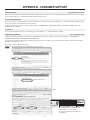
1
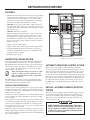
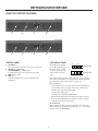
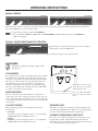
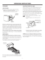
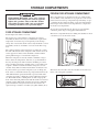
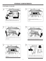
USER MANUAL ® NEA1402 NDA1402 autodefrost FOR YOUR SAFETY If you smell gas: 1. Open windows. 2. Don’t touch electrical switches. 3. Extinguish any open flame. 4. Immediately call your gas supplier. FOR YOUR SAFETY Do not store or use gasoline or other flammable vapors and liquids in the vicinity of this or any other appliance. Pour votre sécurité Si vous sentez une odeur de gaz: 1.Ouvrez les fenêtres. 2.Ne touchez à aucun interrupteur. 3.Éteignez toute flamme nue. 4.Avertissez immédiatement votre fournisseur de gaz. Pour votre sécurité Ne pas entreposer ni utiliser de l’essence ni d’autres vapeurs ou liquides inflammables à proximité de cet appareil ou de tout autre appareil. ! AVERTISSEMENT ! WARNING Improper installation, adjustment, alteration, service or maintenance can cause injury or property damage. Refer to this manual. For assistance or additional information consult a qualified installer, service agency or the gas supplier. Une installation, un réglage, une modification, une réparation ou un entretien non conforme aux normes peut entraîner des blessures ou des dommages matériels. Lisez attentivement le mode d’emploi fourni avec l’appareil. Pour obtenir de l’aide ou des renseignements supplémentaires, consultez un installateur ou un service d’entretien qualifié ou le fournisseur de gaz. ® USA Corporate OfficeCANADA Service Office 2320 Industrial Parkway Elkhart, IN 46515 Dometic Corporation Dometic Corporation 46 Zatonski, Unit 3 2320 Industrial Pkwy. Brantford, ON N3T 5L8 Elkhart, IN 46516 For Service Center Assistance CANADA Phone: 574-294-2511 Call: 800-544-4881 Phone: 519-720-9578 825128201 ©2007-2008 Dometic Corporation LaGrange, IN 46761 MO-M 0802 This product is manufactured under license of U.S. Patent Number 6.019,447 Patents pending U.S. 10/619,675 U.S. 10/620,177 U.S. 10/758,174 U.S. 10/758,175 U.S. 10/760,564 U.S. 10/760,565 introduction Thank you for entrusting us to supply your new quality-guaranteed refrigerator which is to be used as a recreational device designed for storage of foods, frozen foods and making ice. Please, when the refrigerator is not in use as a recreational device, turn the system off and open the door(s). This manual describes how to operate NEA1402 (all-electric) and NDA1402 (2-way operated). Read it carefully to ensure that you know how to operate the refrigerator safely and correctly. Be aware of possible safety hazards when seeing alert symbols on the refrigerator as well as in this manual. The manual should be kept and stay with the refrigerator if it is ever moved or change owners. Servicing should be performed by qualified personnel only! Thus, the section regarding maintenance and service is intended for service personnel. For installation instructions, refer to the Installation manual. contents refrigerator overview_____________________ 4 Features . . . . . . . . . . . . . . . . . . . . . . . . . . . . . . . . . . . . . . . . . . Absorption cooling system. . . . . . . . . . . . . . . . . . . . . . . . . . . . . Automatic defrosting control system. . . . . . . . . . . . . . . . . . . . . NDA1402 - Automatic energy selector system . . . . . . . . . . . . . Using the control features. . . . . . . . . . . . . . . . . . . . . . . . . . . . . 4 4 4 4 5 operating instructions_____________________ 6 Start-up . . . . . . . . . . . . . . . . . . . . . . . . . . . . . . . . . . . . . . . . . . . Settings. . . . . . . . . . . . . . . . . . . . . . . . . . . . . . . . . . . . . . . . . . . Dispensers. . . . . . . . . . . . . . . . . . . . . . . . . . . . . . . . . . . . . . . . . Ice maker. . . . . . . . . . . . . . . . . . . . . . . . . . . . . . . . . . . . . . . . . . 6 6 7 8 storage procedure / winter operation_____ 9 Getting the refrigerator ready for storage . . . . . . . . . . . . . . . . . 9 Draining the ice maker. . . . . . . . . . . . . . . . . . . . . . . . . . . . . . . . 9 Storage compartments____________________ 11 maintenance & service_____________________ 13 troubleshooting_ _________________________ 15 Troubleshooting table . . . . . . . . . . . . . . . . . . . . . . . . . . . . . . . Status messages . . . . . . . . . . . . . . . . . . . . . . . . . . . . . . . . . . Call for service. . . . . . . . . . . . . . . . . . . . . . . . . . . . . . . . . . . . . Service mode. . . . . . . . . . . . . . . . . . . . . . . . . . . . . . . . . . . . . . 15 16 17 17 appendix A - spare parts____________________ 18 appendix B - consumer support_ ___________ 19 appendix C - Dometic warranty & maintenance schedule______________________20 Symbols The following symbols are used throughout the manual: ! WARNING Indicates a potentially hazardous situation, which, if not avoided, could result in death or serious injury. ! CAUTION CAUTION Indicates a potentially hazardous situation, which, if not avoided, may result in minor or moderate injury. Information Step-by-step instructions Used without the safety alert symbol indicates, a potentially hazardous situation which, if not avoided may result in property damage. –– refrigerator overview Features • This side-by-side refrigerator-freezer has two compartments with separate doors. The left one is a frozen food compartment (the freezer) and the right one is a fresh food compartment (the fridge). Both compartments have automatic defrosting and independent temperature controls. • NDA1402: 2-way power option. The cooling system may use either 120V AC or LP gas as energy source for the cooling. Energy selection is made either automatically or manually (forced to gas). NEA1402: All-electric operation. • Models equipped with ice dispenser or both ice and water dispenser: In order to make serving water and ice easier, the refrigerator is equipped with a dispenser for ice cubes and chilled water through the door. Without having to open the freezer it provides water as well as crushed or cubed ice right into the cup. • Climate control cooling system. • Digital controls show current temps in both compartments. • Vacuum insulated panels increase interior storage space. • Automatic front frame heater prevents condensation from forming on exterior cabinet. • Flexible storage options. Absorption cooling system Model shown with ice and water dispenser In an absorption refrigerator system, ammonia is liquefied in the finned condenser coil at the top rear of the refrigerator. The liquid ammonia then flows into the evaporator (inside the freezer section) and is exposed to a circulating flow of hydrogen gas, which causes the ammonia to evaporate, creating a cold condition in the freezer. When starting this refrigerator for the very first time, the cooling cycle may require up to four hours of running time before the cooling unit is fully operational. The tubing in the evaporator section is specifically sloped to provide a continuous movement of liquid ammonia, flowing downward by gravity through this section. Automatic defrosting control system This refrigerator is equipped with an automatic defrosting control system. The defrost system will automatically carry out defrost in frozen food and fresh food compartment once per 24 hours. To be able to control the performance of the defrost intervals the system is equipped with a built in defrost timer. The timer has to be set to local or Central American time at the very first start up of the refrigerator or when the 12V DC supply has been disconnected for a longer period of time. A message on the LED display panel will alert when the defrost timer needs to be set. Leveling the refrigerator Leveling is one of the requirements for proper operation with absorption refrigerators. To ensure proper leveling the vehicle needs to be leveled so it is comfortable to live in (no noticeable sloping of floor or walls). Any time the vehicle is parked for several hours with the refrigerator operating, the vehicle should be leveled to prevent this loss of cooling. If the refrigerator is operated when it is not level and the vehicle is not moving, liquid ammonia will accumulate in sections of the evaporator tubing. This will slow the circulation of hydrogen and ammonia gas, or in severe cases, completely block it, resulting in a loss of cooling. When the vehicle is moving, the leveling is not critical, as the rolling and pitching movement of the vehicle will pass to either side of level, keeping the liquid ammonia from accumulating in the evaporator tubing. NDA1402 - Automatic energy selector system This refrigerator is equipped with an automatic energy selector system which automatically selects the most suitable energy source that is available, either 120 V AC or LP gas operation. The system can be set by the user to be fully automatic, or to operate on LP gas only. –– ! WARNING FIRE OR EXPLOSION HAZARD. When refueling or parked near gasoline pumps, shut off all LP gas appliances. Failure to heed this warning could cause a fire or explosion resulting in death or severe personal injury. refrigerator overview Using the control features NEA1402 1 2 3 4 NDA1402 1 2 3 4 Control panel LED display panel 1. ON/OFF key. Press this button to turn the refrigerator on and off. 2. STORE key (NEA1402) AUTO/STORE key (NDA1402) Combined energy mode selection and store key. 3. LED display panel 4. SET key Combined temperature range and defrost timer adjustment. The LED panel displays preferably temperatures in the refrigerator, current modes of operation and other useful status messages. PM AC (NEA1402) FREEZER FRIDGE PM AUTO AC GAS FREEZER FRIDGE (NDA1402) The displayed temperature values reflect the storage temperatures of the food in the two compartments. A delay function prevents rapid changes due to door openings etc. Panel indications: • Actual temperature of food in frozen food compartment. • Actual temperature of food in fresh food compartment. • AUTO mode indication (NDA1402) • AC operation indication. • GAS operation indication (NDA1402) • Thermostat setting indication (temporary during setting). • Defrost timer/ PM indication (temporary during setting). • Various status and error messages. Store function When setting the defrost timer as well as the thermostat, the desired setting is stored automatically after 5 sec. of inactivity or by pressing the STORE key. –– operating instructions Start-up NEA1402 Turn on the refrigerator by pressing the ON/OFF key. NDA1402 ! WARNING FIRE HAZARD. Before lighting the gas burner, after that the RV has not been used for some time, please check that the gas path between the burner jet and the burner tube has not been obstructed. Failure to heed this warning could cause a fire resulting in personal injury. SOLENOID VALVE 1. Before turning on the refrigerator, please verify that all the manual gas valves, including the manual shut off valve, are in the ON position. 2. Turn on the refrigerator by pressing the ON/OFF key. BURNER MOUNTING SCREWS INLET FITTING BURNER JET BURNER TUBE . SPARK ELECTRODE Settings Set defrost timer PM INDICATION MANUAL SHUT OFF VALVE Shown in open position PRESSURE TEST PORT NEA1402 HOURS NDA1402 MINUTES PM INDICATION HOURS MINUTES NOTE! The defrost timer must be set in order for the automatic defrosting system to work properly. For further information, see Refrigerator overview > Automatic Defrosting SysteM. If the defrost timer has to be set, the LED panel will show flashing horizontal bars ” -- -- “. 1. To enter TIMER MODE keep SET key pressed until figures flash on the LED panel. (Hours are to the left and minutes to the right.) 2. Press the SET key to adjust to local or Central American time. PM/AM should also be set here. . Store each setting by pressing AUTO key (NEA 1402) - AUTO/STORE key (NDA 1402) - or use the automatic store function (wait 5 sec.). Set thermostat range NDA1402 temperature control The freezer and the fresh food compartment temperatures are controlled separately and independently of each other, based on the actual air temperature in each compartment. The compartment temperatures will be the same regardless of ambient temperature or setting in the other compartment. • The freezer setting is pre-set (can not be changed) to be approx. 0F (-18°C) when running on AC. If running on GAS the pre-set temperature is approx. 7F (-14°C). • The fresh food compartment can be set in 5 different positions (1-5) where 5 is the coldest setting which give a fresh food temperature of approx. 33F (0°C). Setting 3 gives a temperature of approx. 37F (3°C). NEA1402 NDA1402 1. Press the SET key to set the thermostat. Thermostat range is 1 to 5, where 5 represent the coldest compartment temperature. 2. Press the STORE key to store or use the automatic store function (wait 5 sec.). –– operating instructions Manual defrost NEA1402 NDA1402 The refrigerator can be set to defrost at any time. Usually a defrost cycle takes about 1 hour but is depending on the amount of frost and could therefore vary from time to time. 1. Switch off the refrigerator with the ON/OFF key. 2. Press and hold the AUTO key (NEA 1402) - AUTO/STORE key (NDA 1402). Then, press the ON/OFF key. “dE Fr” is displayed. NDA1402 - Select energy mode of operation Current mode of operation and energy source (AC or GAS) is indicated by a dot on the LED panel. Press AUTO/STORE key to select Auto mode operation or lock up to LP-gas mode operation only. Dispensers Information applicable for models equipped with dispenser(s). Ice Dispenser Cube Crush Light ICE Ice dispenser For a refrigerator to provide ice through the door, the ice maker first dumps the ice it produces into a large bin. To request ice at the door, select Cube or Crush and then press the lever. This will activate a switch which turns on a motor that rotates the auger. When the auger rotates, it pushes ice out of the bin, through a chute right into the glass. To stop dispensing, pull glass away from dispensing arm before the glass is full. Allow ice chute to clear before removing glass. Lock WATER The drip tray catches small spills. The tray is removable and dishwasher safe. Water dispenser It is not a drain; DO NOT pour water directly into this area! The water dispenser works much like the ice dispenser. To request water at the door, simply press the lever. This will activate a switch which turns on an electric water valve at the back of the refrigerator. Water will flow through a separate tube right into the glass. Lock out feature Dispenser light The ice dispensing system can be locked out to prevent unwanted use. • Lock Out To lock out, press the “Padlock” pad for 3-5 seconds until the RED light above the Padlock comes on. • Unlock To unlock, press the “Padlock” pad for 3-5 seconds until the RED light above the Padlock goes out. The light can be turned on and off by pressing the light touch pad. The light will illuminate the dispenser area. The light will also turn on automatically when the ice is dispensed. Automatic power supply switch off For safety reason, when opening the freezer door, the ice dispensing and ice maker system will automatically shut off its function. Closing the freezer automatically resume operation of ice dispensing and ice maker operation. –– operating instructions Ice maker Adjusting the size of cubes How it works Before the ice maker can operate, make sure that the: • Refrigerator is connected to 120 V AC. • Water valve supplying the refrigerator is turned on. • Ice level bail arm is in its fully down position. Ice level bail arm The first container of ice cubes should be dumped if the water system has been winterized or not used for several weeks. Note that if the ice maker have been cleaned and drained, no ice cubes will be dumped into the bin during the first cycle. The first few cycles may produce small cubes due to air trapped in the water lines. Once the ice maker has run through several cycles and if the cubes are too small or sticking together, adjustment is necessary on the amount of water entering the mold. To adjust the size of cubes, follow these steps: 1. Remove the protective cover from the ice maker mechanism. 2. Locate the adjusting screw under the protective cover. Adjusting screw Down position When the ice maker thermostat senses the preset temperature for the ejection of the ice cubes, the fingers will start to rotate, dumping any ice cubes and filling the mold with water. When the storage container is full, the bail arm will come in contact with the ice cubes. The bail arm cannot return to the full down position and the ice production is stopped until the bin is emptied, or ice cubes are removed. When on the road, the water in the icemaker might, depending on road conditions, splash out of the mold. To avoid splashing, the mold needs to be either empty - or - the water in the mold must be frozen. Water supply The water supply system must have a minimum pressure of 15 pounds per square inch gauge (psig). Use a 1/4” diameter water line to the water valve at the rear of the refrigerator. The water line must have a manual shutoff valve placed where it is easily accessible. The maximum water level is represented by a thin line. It is essential that the water level does not exceed this line! Cover . To increase the size of cubes, turn the screw counter clockwise. To decrease the cube size or if the cubes are stuck together, turn the screw clockwise. NOTE! To prevent overfilling, DO NOT turn the adjustment screw more than one revolution at a time. Allow the ice maker to cycle several times before another adjustment is made. Be sure to replace the protective cover on the cycle after the adjustments are complete. Maximum water level If necessary change the water flow by adjusting the water supply, see the step-by-step instruction in adjusting the size of cubes. –– storage procedure / winter operation Getting the refrigerator ready for storage The refrigerator is equipped with a heater tape wrapped around the water solenoid valve and outlet water tube. During cold weather operation below 32°F/0°C the automatic temperature switch will turn the heater tape on automatically. NOTE! The refrigerator automatic heater tape doesn’t work when the refrigerator is shut off. Summer short-time storage The coach’s Air Conditioner (A/C) is recommended to be left on to prevent/reduce condensation. If the A/C is switched off, while leaving the refrigerator on, the air humidity will increase and form condensation on the outside of the refrigerator. If the refrigerator is on, the A/C should be on. Consequently, if the A/C cannot be left on, please shut off the refrigerator as well. Should the weather get cold during a period of short-term storage, follow the procedure for longer-term storage as described below. Long-term storage If the RV will not be in use for an extended period of time or put into storage: • Drain the RV water system. • Disconnect the water lines from the inlet and outlet sides of the water valve. Drain the lines into a cup and allow the lines to dry. • The ice maker should be drained and dried, see Draining the ice maker. • Using a lukewarm soda solution, clean the interior liner of the refrigerator. Clean the finned evaporator, ice trays and shelves. Use warm water only and never strong chemicals or abrasives since these can damage the protective surfaces. • Leave the doors ajar. Draining the ice maker If the RV is in storage and the refrigerator or the DC power is turned “OFF” there will be no 12V DC present to operate the heat tape; therefore, it will be necessary to drain and dry the ice maker. This will prevent water from freezing in the solenoid valve or becoming stale and producing bad tasting ice. If the temperatures are expected to reach or exceed 0°F/-18°C the ice maker must be drained to prevent component damage and leaks. Note! Water, compressed air and AC power are required to drain the ice maker. Draining of the ice maker must be done by a qualified service technician. To drain the ice maker, follow these steps: 1. Shut off water supply valve to the ice maker. 2. Place a shallow pan under water solenoid valve. . Remove the hose from the inlet fitting to the water solenoid valve. 4. Drain water from the supply line. Water inlet hose Water solenoid valve Hose, ice maker Hose, water dispenser 90º connection, water dispenser Drain water hose Rearview of models equipped with ice & water dispenser CAUTION Do not use: • A knife or an ice pick, or other sharp tools to remove frost from the freezer shelves. It can create a leak in the ammonia system. • A hot air blower. Permanent damage could result from warping the metal or plastic parts. –– storage procedure / winter operation 5. Remove the plastic nut(s) and water line(s) from outlet side of the water solenoid valve. 10. Start the harvest cycle with a flat blade screw driver inserted into the center of the small gear. Water solenoid valve Refrigerator with ice maker or ice maker & ice dispenser Water solenoid valve Inlet fitting for water supply line Plastic nut Metal tube 11. Turn the gear counter clockwise, when the hold switch closes, the mold assembly will continue to operate through the harvest cycle. During the water fill sequence of the harvest cycle the compressed air will blow out the water trapped in the solenoid valve. Up to 20 PSIG air pressure can be used to clear the solenoid valve. 12. Repeat the harvest cycle operation several times. 1. Refrigerator with ice and water dispenser. - Clear the water part of the solenoid valve. Press the lever to open the valve and then, apply compressed air to blow out the water trapped in this part of the valve. - Blow out the water from the water dispenser hose. Use compressed air as shown in the figure below. 1/4” Water line to ice maker Water solenoid valve Refrigerator with ice & water dispenser Water inlet hose Inlet fitting for water supply line Ice Water Plastic nut: • Ice: 7/16” - 20 UNF • Water: 1/2” - 20 UNF Ice Dispenser Cube Crush Light ICE Outlet connection tubing: • Ice: 1/4” plastic hose • Water: 5/16” plastic hose 6. Drain water from the line. 7. Connect compressed air onto the inlet fitting of the water solenoid valve. 8. Apply AC power to the solenoid valve by forcing the ice maker mold assembly through several harvest cycles. Note! Damage to the solenoid can occur if AC power is applied for more than 20 seconds. 9. Remove the plastic cover from the mold assembly. The bail arm must be in the down (“ON”) position. – 10 – Lock WATER Apply compressed air 14. Reconnect and tighten the lines on water solenoid valve. Make sure that the metal tube is in the plastic water line to the ice maker. 15. Leave the water supply turned off until temperatures are above 0°F/-18°C. 16. Dry the ice maker mold assembly with a soft cloth. 17. Place bail arm in the “UP/OFF” position. Storage compartments Frozen food storage compartment ! WARNING This compartment is not designed for deep or quick freezing of food. Meat or fish, whether raw or prepared, can be stored in the frozen food storage compartment provided they are precooled first in the refrigerator. They can be stored about three times longer in the frozen food compartment as compared to the fresh food compartment. EXPLOSION HAZARD. Never store explosive substances in the refrigerator, such as cigarette lighter fuel, gasoline, ether or the like. Failure to heed this warning could cause an explosion resulting in death or severe personal injury. To prevent food from drying out, keep it in covered dishes, containers, plastic bags or wrapped in aluminum foil. Food storage compartment The freezer compartment has two sliding wire baskets for more convenient access to the frozen foods. Total refrigerated volume: 14.0 cu.ft. The food storage compartment is completely closed and unventilated, which is necessary to maintain the required low temperature for food storage. Consequently, foods having a strong odor or those that absorb odors easily should be covered. Vegetables, salads etc. should be covered to retain their crispness. The coldest positions in the refrigerator are under the cooling fins and at the bottom of the refrigerator. The warmer areas are on the upper door shelves. This should be considered when placing different types of food in the refrigerator. When the refrigerator is heavily loaded, it will take a longer time to lower the temperature; therefore, to get maximum efficiency the refrigerator and food items should be precooled prior to loading. The shelves should not be covered with paper or plastic, and the food items should be arranged so air can circulate freely. The food must not block the circulation of air. If you need more space in the refrigerator you can lift up the front of the second shelf from the top and push the shelf in, the shelf will fall down against the finned evaporator. This shelf cannot be relocated to a different position within the refrigerator. The middle shelf is a sliding shelf, to slide out grasp the front of the shelf and pull forward. Push the shelf in to return to original position. This shelf cannot be relocated to a different position within the refrigerator. The lower door shelf is designed for large containers or bottles (1/2-gallon milk or juice). The freezer door has three wire door baskets for frozen food items, such as bagged vegetables. – 11 – Storage compartments positioning of shelves 2 1 Slide the wire shelf to the left. The right-hand side of the shelf will come loose. Put a screwdriver into the slot of the shelf lock. Turn the screwdriver counter clockwise. Remove the shelf locks from the wire shelf. 3 4 Lower the right-hand side of the wire shelf and let the left-hand side slide out of the holes in the wall. Insert the ends of the wire shelf on the left-hand side at the desired position. 6 5 Slide the plastic plugs into the holes of the wall. Snap the shelf locks onto the wire shelf. Slide the shelf into the holes on the righthand side. – 12 – maintenance & service • Always keep the food compartment and the freezer clean. • If the refrigerator will not be in operation for a period of weeks it should be emptied, defrosted, cleaned and the doors left ajar, see storage procedure / winter operation. • Periodic inspection, cleaning and maintenance of the refrigerator is recommended. - Make sure the area behind the refrigerator is clear and free from combustible material, gasoline and other flammable vapors or liquids. - Dust off the coils on the back of the refrigerator (use a soft brisled brush). - Make sure the upper and lower vents are free from any obstructions. CAUTION If your refrigerator stops cooling, immediately turn the refrigerator off and see a Dometic dealer. NDA1402 • Check the burner flame for proper appearance. The flame should be light blue. • A qualified service technician should, at least once a year, inspect the connections, the control system, the LP gas pressure and the flue baffle, see periodic maintenance. The following instructions are applicable for NDA1402. The procedures described in Periodic maintenance are to be performed by service personnel only. Periodic maintenance Checking the connections 1. Check all connections in the LP gas system (at the back of the refrigerator) for gas leaks. The LP gas supply must be turned on. 2. Apply a non-corrosive bubble solution to all LP gas connections. The appearance of bubbles indicates a leak and should be repaired immediately by a qualified serviceman. Checking the LP gas pressure The LP gas pressure should be checked and the main regulator readjusted if pressure is incorrect. The correct operating pressure is 11 inches of water column. Measure the LP gas pressure at the test port, just ahead of the burner jet. Gas equipment assembly SOLENOID VALVE BURNER MOUNTING SCREWS ! WARNING EXPLOSION HAZARD. Never use an open flame to check for gas leaks. Failure to heed this warning could cause an explosion resulting in death or severe personal injury. INLET FITTING BURNER JET BURNER TUBE . SPARK ELECTRODE – 13 – MANUAL SHUT OFF VALVE Shown in open position PRESSURE TEST PORT maintenance & service Cleaning the flue and burner Inspect the flue baffle. It should be reasonably clean and free of soot. Heavy soot formation indicates improper functioning of the burner. To clean the flue and burner, follow these steps: 1. Unplug the refrigerator power cord from the 120V AC outlet. 2. Disconnect/shut off the 12V DC power to the refrigerator. . Turn the manual shutoff valve to OFF. 4. In turn, remove the: - Cover from the burner housing. - Burner mounting screw and burner assembly. - Wire and flue baffle from the top of flue tube. 5. Using a flue brush, clean the flue from the top. Blowing compressed air into the flue will not properly clean soot and scale out of the flue tube. 6. Replace the flue baffle. 7. Clean the burner tube with a brush. Blow out the burner with compressed air. 8. Before removing the burner jet, clean burner area of soot and scale that fell out of flue tube. 9. Remove the burner jet. 10. Soak the jet in wood alcohol and blow it out with compressed air. ! WARNING FIRE HAZARD. Do not use a wire or pin when cleaning the burner jet as damage can occur to the precision opening. Failure to heed this warning could cause fire resulting in personal injury. 14. Turn on the manual gas shutoff valve. Check all fittings for leaks with soapy water. 15. Connect the 120V power cord to the outlet. Reconnect/turn on the 12V DC power. 16. Check the LP gas safety shutoff. Replacing the heater The heat necessary for the operation of an absorption cooling unit is supplied by an electric heater mounted in a pocket of the boiler system. The refrigerator is equipped with a series connected twin heater. To replace the heater, follow these steps: 1. Disconnect 120v ac and 12v dc power. 2. Remove the protection cover. . Remove the power module cover. 4. Disconnect the heater leads. 5. With a pair of pliers, unfold the lug holding the lid of the boiler casing and open the lid. 6. Remove some insulation wool so that the heater is accessible. 7. Turn and lift the heater out of its pocket. 8. Fit the new heater into the pocket. 9. Connect the leads. 10. Put back the power module cover. 11. Put back the insulation wool. Close the lid of the boiler. 12. Put back the protection cover. Replacing the fuses Power module To replace the fuses, follow these steps: 1. 2. . 4. 5. 11. Reinstall and tighten the burner jet. 12. Carefully reinstall the burner. Make sure the end of the burner fits into the slot on the burner bracket and that the slots are centered under the flue tube. Disconnect 120v ac and 12v dc power. Remove the power module cover. Snap the fuse out of the fuse holder. Fit a new fuse in to the fuse holder. Put back the power module cover. inline fuse The 3 A inline fuse for the power vent fans is connected to the 12V DC socket. To replace the inline fuse, follow these steps: 1. Disconnect 12v dc power. 2. Open the fuse holder. 4HEFLAMESHOULDBE CLEARBLUEOVERTHE SLOTSOFTHEBURNER . Replace the fuse. 1. Check the electrode for proper location and gap. Electrode 4. Put the holder back together. 1/8” to 3/16” (3-5 mm) Burner tube – 14 – troubleshooting Troubleshooting table If you run into a problem, refer to the troubleshooting table below. Symptom Check/Remedial action The refrigerator has stopped cooling. • Immediately turn the refrigerator off and see a Dometic dealer. The refrigerator does not work on 120V AC • Defective fuse? Fit a new fuse. • Connection to supply voltage? Establish power connection. Refrigerator or freezer is not cold enough • Is the plug firmly connected to the socket? Is the socket switched on? Check the socket by plugging in another appliance. • Is the thermostat properly set? • Is the refrigerator level? Because of its operation it is important to keep an absorption refrigerator level. • Heavy frost build-up on evaporator fins? To prevent frost buildup, which can reduce efficiency, do not leave the unit’s door open longer than necessary. • Has the overheating protection been triggered or not? (Must be checked by an authorized service technician.) • Is there a power failure? Are the fuses intact for the AC supply and control system? • Has the door been closed properly? If not it can cause the inside temperature to rise. • Overpacked refrigerator? The unit will have to work harder if the refrigerator is stuffed and results in higher cabinet temperatures. Arrange the food in the unit to allow for free air circulation. • Venting problem? Restriction in air flow across cooling unit? Ensure that there is sufficient clearance between the refrigerator and the surrounding walls to allow for proper air circulation around the unit. NDA1402 • Is the burner dirty, damaged or not properly located under the flue tube? • Is the burner jet clogged? • Is the flue baffle inserted properly in the flue tube? • Is the LP gas pressure low at burner? Set the main regulator to regulate the pressure so it does not drop below 11 inches water column at pressure tap. The refrigerator does not work in gas operation mode • Gas bottle empty? Change the gas bottle • Air in the gas pipe? Remove the air by switching the refrigerator on and off 3-4 times. Odors from fumes • Dislocated burner • Damaged burner • Dirty flue tube If the problem persists and the refrigerator is still not working properly, contact your nearest Service Center. State the problem, model, product- and serial-number. (These details are stated on the data label inside the compartment.) – 15 – troubleshooting Status messages Led display panel Status message Steady display Flashing ”dE Fr” Defrosting is just now performed X ” x “ x is a figure 1-5 Thermostat range setting indication X ”ch LP” Gas operation problem (NDA1402) 1 X ”Lo dc” DC voltage too low to start defrosting 2 X ”-- --” Defrost timer not set (defrost timer needs to be set) 3 X ”Er 01” Defrosting problem i.e. two uncompleted defrost sequences after each other 4 X ”Er 02” Fan in frozen food compartment is blocked 5 X ”hl” in actual temp. field Temperature is above measurement range 6 ”CA LL” and an error code Severe faults 7 (Alt. between temp. and message) X X Check to make sure that the LP-gas supply tanks are not empty and all manual shut off valves in the lines are open. If the refrigerator has not been in used for a long time or if the LP tanks just have been refilled, air may be trapped in the supply lines. To purge the air from the lines may require resetting the ON/OFF key several times. 2 The DC voltage has for 3 hour period been too low to start a defrost sequence. Check battery charge level regular to overcome low DC voltage situations. Check the setting of the defrost timer, if necessary adjust to local or Central American time. 3 Refer to section SETTINGS. 1 Defrosting has been insufficient twice in a row (48 h) either because of the DC voltage being too low or no cooling source available or because of too much frost builds up. Check battery charge level regular to overcome low DC voltage situations. Check for proper wire size. For further information, refer to Installation > 12V DC Connection. Use the manual defrost function to overcome excess of frost build up. 5 The fan has been blocked and is not circulating the air in the freezer compartment. Check the fan by unscrewing the bottom part of the fan housing. Try to rotate and look for ice build or other parts that can interfere with the rotation of the fan. 6 The compartment temperatures are warmer than 41°F in freezer and 59°F in fresh food compartment. 4 7 Refer to section Call for service. – 16 – troubleshooting Call for service NEA1402 NDA1402 If the message “CA LL” is displayed on the LED panel a technical fault that need attention by Dometic personal has occurred. Call a Dometic service center for assistance as soon as possible and notify displayed error code to the service agent. Toll free number (800) 544-4881. Error Message displayed Heating element in frozen food compartment faulty ”Er 11” Heating element in fresh food compartment faulty ”Er 12” Heating element in drain pipes faulty ”Er 13” Fan in frozen food compartment faulty ”Er 14” Fan in fresh food compartment faulty ”Er 15” Air temperature sensor in frozen food compartment faulty ”Er 16” Air temperature sensor in fresh food compartment faulty ”Er 17” Temperature sensor on cooling surfaces in frozen food compartment faulty ”Er 18” Temperature sensor on cooling surfaces in fresh food compartment faulty ”Er 19” Service mode NEA1402 NDA1402 Service mode is intended as a tool for service personnel only in order to perform diagnostic troubleshooting. Before entering service mode: 1. Switch off the refrigerator with the ON/OFF key. 2. To enter service mode, press and hold SET key. Then, press the ON/OFF key. . Press the SET key to toggle the list of functions step by step. No Instruction 00 Note — — 01 LED panel check All LED segments ON 02 Battery voltage check ”12” ➞ in range between 8,5 - 18 V DC “Lo” or “hl” ➞ out of range 03 Air temperature sensors, freezer + fridge Value in °F ➞ in range, “hl” or “Lo” ➞ out of range, “--” ➞ sensor fault 04 Surface temperature sensors, freezer + fridge Value in °F ➞ in range, “hl” or “Lo” ➞ out of range, “--” ➞ sensor fault 05 Door switches status ”OP” ➞ open, “CL” ➞ closed 06 Turn AC heater ON ”ON” ➞ turned on, “no AC” ➞ problem 07 Turn fridge heater ON ”ON” ➞ turned on, “--” ➞ problem 08 Turn freezer heater ON ”ON” ➞ turned on, “--” ➞ problem 09 Turn drain heater ON ”ON” ➞ turned on, “--” ➞ problem 10 Turn door heater ON ”ON” ➞ turned on 11 Turn fridge fan ON ”ON” ➞ turned on, “--” ➞ problem 12 Turn freezer fan ON ”ON” ➞ turned on, “--” ➞ problem or “bL” ➞ blocked 13 Turn gas ignition system ON (NDA 1402) ”FL” ➞ turned on flame, “ 9” ➞ sparking, “--” ➞ problem – 17 – appendix A - spare parts Contact an authorized service center for parts and repairs as needed. For replacement parts suppliers, see the front page of this manual. Below you will find a list of commonly used parts which should be available from your Dometic Service Center. Description Part No. Baffle (NDA1402) 293 26 67-05/4 Bottle holder, 5 pieces 293 26 58-01/2 Burner pipe, cpl. (NDA1402) 95 50 01-67/2 Crisper, 2 pieces 385 04 42-01/7 Door shelf, 2 pieces 293 25 77-03/0 Door shelf, 3 pieces (upper) 293 25 83-04/6 Door shelf, (lower) 385 04 45-01/0 Electrode with conductor (NDA1402) 293 27 81 02/0 Heater, 120V, 420W (2 x 60V, 210W) 385 06 44-53/9 Jet, no. 76 (NDA1402) 200 74 19-33/2 Lamp 200 72 90-00/6 Lamp cover 385 09 62-01/4 – 18 – appendix B - consumer support Dometic website www.dometicusa.com Please visit the website for information and news about Dometic products. You can obtain information about how to get in contact, learn about product care, download manuals, leaflets and warranties. Service and spare parts For service, please contact the Service Center Assistance, see the front page of this manual - or - visit the Dometic website to find the location of the nearest Dometic Service Center. Commonly used spare parts are listed in this manual, see Appendix A - Spare parts. These should be available from your Dometic Service Center. Contact us For contact information, please see the frontpage of this manual - or - visit the Dometic website. Register the appliance www.edometic.com Timely registration will allow for enhanced communication and service under the terms of the warranty, see Appendix C dometic warranty & maintenance schedule. To register the appliance, fill in the pre-printed registration card on the last page of this manual or register on-line at the Dometic website www.edometic.com. To register on-line, follow these steps: 1. At www.edometic.com, click Warranty Registration. 2. Click Register your new Dometic product here. . Complete the information and then, click the Submit Registration button. The model number (e.g. RM3762) and serial number ( e.g. 012 34567) are stated on the data label in the refrigerator compartment. – 19 – appendix C - Dometic warranty & maintenance schedule important! Valuable Dometic Refrigerator Warranty & Maintenance Schedule Congratulations, and Thank You for purchasing the industry’s best built and best backed RV Refrigerator. Enclosed you will find important warranty and maintenance information on Dometic’s exclusive three (3) year warranty. Please take a few moments and familiarize yourself with the program. We at Dometic appreciate your business and are confident that you will have many years of trouble-free RV enjoyment. – 20 – Limited three-year warranty dometic refrigerators THE SELLER NAMED BELOW MAKES THE FOLLOWING WARRANTY WITH RESPECT TO THE DOMETIC PRODUCT: 1. This warranty is made only to the first purchaser (herein after referred to as the “Original Purchaser”) who acquires the product for his own use and is installed and operated within the continental United States and Canada. 2. This warranty will be in effect for three years on parts and freight and two years on labor from the date of purchase by the Original Purchaser. It is suggested that the original purchaser retain a copy of the dated bill of sale as evidence of the date of purchase. . This warranty covers only specified parts, which shall be free from defects in material and workmanship under normal use. This warranty does not cover conditions unrelated to the material and workmanship of the product. Such unrelated conditions include, but are not limited to: (a) damage not reported within the first 7 days of ownership; (b) faulty installation or installation that does not comply with RVIA standards, and any damage resulting from such; (c) the need for normal maintenance and any damage resulting from the failure to provide such maintenance; (d) failure to follow Sellers instructions for use of product; (e) any accident to or misuse of any part of this product and any alteration by anyone other than the Seller or its authorized representative; (f) any non-Dometic parts that are installed as replacement parts will void any warranty (implied or written); (g) blow out conditions; (h) radio frequency interference and electromagnetic interference; (i) 12V system chassis ground decay and corrosion; (j) puncture of foam cabinet or vacuum insulated panels after acknowledged receipt; (k) animal or insect infiltration which damages unit or inhibits performance; (l) abuse or misuse of electrical components. 4. The specified parts covered by this warranty are as follows: Major components (cooling unit, LP gas valve, burner, burner housing, electronic display, electronic module, evaporator fins, foam integrity, frame, thermister, spark probe, ignition wire, icemaker compressor, second absorption loop, display escutcheon, lower toe plate, humidity switch, frame heater mullion, icemaker mullion) are covered for parts and freight for three years and labor for two years from date of purchase. All other components that fail must be reported within the first 90 days of ownership in order to receive coverage of parts, freight and labor under warranty. 5. This warranty requires the Original Purchaser to provide preventative maintenance on a yearly basis, starting at the anniversary of his date of purchase. The Original Purchaser must keep a record of the preventative maintenance to keep the warranty in effect. Failure of the Original Purchaser in providing this annual maintenance may void the warranty. The preventative maintenance must be performed at a Dometic Authorized Service Center/Dealer. The preventative maintenance required is an inspection, cleaning and full diagnostics performed on the entire electronic system, burner assembly, wiring and cooling unit. A copy of the receipt covering the maintenance checks must accompany the warranty claim during the second and third year of ownership. The cost of this preventative maintenance is the Original Purchaser’s responsibility and should take about one hour. 6. In order to obtain the benefits of this warranty, the original purchaser must return the product which is found defective to the Seller named below or to a Dometic Authorized Service Center during the period that this warranty is in effect. The original purchaser is responsible for all charges incurred in delivery of the product to the Seller or Dometic Authorized Service Center, and in pick up after the warranty service has been completed. To obtain the location of the nearest Authorized Service Center, please call 1-800-544-4881 or in Canada call 1-519-720-9578. 7. Any item returned in the manner described in paragraph 6 will be examined by the Seller or the Authorized Dometic Service Center. If it is found that the returned item was defective in material and workmanship, the Seller or the Authorized Dometic Service Center will repair the product per the terms outlined in paragraph 4. CONFIRM THE SERVICE AGENCY IS AN AUTHORIZED DOMETIC SERVICE CENTER. DO NOT PAY THE SERVICE AGENCY FOR WARRANTY REPAIRS. SUCH PAYMENTS WILL NOT BE REIMBURSED. 8. The Seller does not authorize any person or company to create any warranty obligations or liability on their behalf. This warranty is not extended by the length of time which you are deprived of the use of the product. Repairs and replacement parts provided under the terms of this warranty shall carry only the non-expired portion of this warranty. 9. In no event shall either seller be liable for incidental or consequential damages. This includes any damage to another product or products resulting from such a defect. Some states do not allow the exclusion or limitation of incidental or consequential damages, so the above limitations may not apply. 10. Any implied warranty, including the implied warranty of merchantability and fitness for any purpose, is limited to the duration of this limited warranty. Some states do not allow limitations on how long an implied warranty can last, so the above limitation may not apply. 11. THIS WARRANTY GIVE SPECIFIC LEGAL RIGHTS, YOU MAY ALSO HAVE OTHER RIGHTS WHICH VARY FROM STATE TO STATE. No action to enforce this warranty shall be commenced later than ninety (90) days after the expiration of the warranty period. Claims must be submitted in writing to the Dometic Warranty Department for arbitration. 12. All products (except those specifically built for commercial use) are warranted only when installed on vehicles built to R.V.I.A and C.R.V.A, Z-240 Standards. 1. The Seller reserves the right to change the design of any product without notice and with no obligation to make corresponding changes in products previously manufactured. DOMETIC CORPORATION Warranty Department 2320 Industrial Parkway Elkhart, IN 46516 Phone: 574-294-2511 Fax: 574-293-9686 – 21 – refrigerator owner maintenance yearly record #USTOMER .AME !DDRESS #ITY 0HONE -ODEL .O 3ERIAL.O 3TATE $ATEOF0URCHASE :IP#ODE 3%#/.$9%!2 &)2349%!2 Dealership: Date: Dealership: Address: Address: City: State: City: Date: State: Phone: Zip: Phone: Technician: Zip: Technician: Cleaned Burner Assembly: Yes / No Cleaned Burner Assembly: Yes / No Cleaned/Check All Terminals Connections: Yes / No Cleaned/Check All Terminals Connections: Yes / No Cleaned/Inspect All Ground Connections: Yes / No Cleaned/Inspect All Ground Connections: Yes / No Inspect and Test Door Seals: Yes / No Inspect and Test Door Seals: Yes / No Inspect and Tighten LP Lines: Yes / No Inspect and Tighten LP Lines: Power Ventilator Installed: *Gas Safety Shutdown in 45 seconds: !#45!, Yes / No Power Ventilator Installed: Yes / No *Gas Safety Shutdown in 45 seconds: 30%#2!.'% !#45!, Yes / No Yes / No Yes / No 30%#2!.'% Electrode Gap 3/16" Electrode Gap Thermister Reading 7-10,000 ohms @ 32° Thermister Reading 7-10,000 ohms @ 32° *D/C Voltage 9.5 to 15 volts D/C *D/C Voltage 9.5 to 15 volts D/C *A/C Voltage 120 Volts ± 10% *A/C Voltage 120 Volts ± 10% Thermocouple Reading 25-35 Millivolts Thermocouple Reading 25-35 Millivolts *Delay Between Modes Approx. 5 seconds *Delay Between Modes Approx. 5 seconds * Use PAL RV Diagnostic Tool for these tests. * Use PAL RV Diagnostic Tool for these tests. )#%-!+%2-/$%,3 Inspect Water Valve and All Connections: )#%-!+%2-/$%,3 Yes / No Inspect Water Valve and All Connections: Inspect Heat Tape Switch for Proper Operation: 3/16" Yes / No Inspect Heat Tape Switch for Proper Yes / No Operation: – 22 – Yes / No Protection for Your New Investment We truly appreciate that you have chosen to purchase a Dometic product for your recreational vehicle and we want to help you protect this wise investment. We at Dometic back our products with one of the most comprehensive warranties in the industry. Complete the registration card below and mail to us or register your Product on-line at www.edometic.com. TIME-DATED MATERIAL Please Process Promptly! Tape here first class postage required ® Dometic Processing Center 2320 Industrial Parkway Elkhart, IN 46516 Tape here ■ Warranty verification ■ owner confirmation ■ factory communication ■ 3 plus 3 service contract Your prompt registration records your right to protection under the terms and conditions of your warranty. Returning your card of registering on-line guarantees you will receive product information and specials. Leaving your email address below will allow us to communicate with you quickly and efficiently. Your completed Owner’s registration card serves as confirmation of ownership in the event of product damage or theft. Returning the card below or registering on-line assures you of an invitation to take advantage of an Optional 3 Plus 3 Full Service Contract which allows you to add up to 3 years of additional warranty coverage. Return the card within 10 days to ensure your: ■ warranty verification ■ factory communication Owner’s Registration Card Registering your product is an essential step to ensure that you receive all the benefits you are entitled to as a DOMETIC customer. Complete the information below and mail to us or register on-line at www.edometic.com. Be sure to include your email address so that we can communicate with you quickly and efficiently. Your address will remain confidential and will not be distribute to third parties. Name Address City Stat/Prov. Date of Purchase MO day year Zip/Postal Code Email Address Refrigerator model number serial number TO THE INSTALLER ® — T: N A hin RT Wit PO rn ays M I etu 0 d R 1 TO THE CONSUMER Fold here. Close with tape. PLEASE AFFIX THESE INSTRUCTIONS TO THE REFRIGERATOR ■ 3 plus 3 service contract PLEASE RETAIN THESE INSTRUCTIONS FOR FUTURE REFERENCE ■ owner confirmation