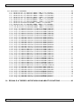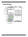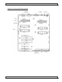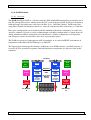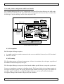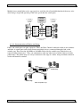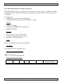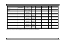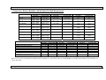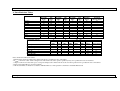
1
Bull ESCALA Tower PL & S, E,T
Reference Guide
ORDER REFERENCE
86 A1 84HX 20
Bull ESCALA Tower PL & S, E,T
Reference Guide
Hardware
December 2003
BULL CEDOC
357 AVENUE PATTON
B.P.20845
49008 ANGERS CEDEX 01
FRANCE
ORDER REFERENCE
86 A1 84HX 20
The following copyright notice protects this book under the Copyright laws of the United States of America
and other countries which prohibit such actions as, but not limited to, copying, distributing, modifying, and
making derivative works.
Copyright
Bull S.A. 1992, 2003
Printed in France
Suggestions and criticisms concerning the form, content, and presentation of
this book are invited. A form is provided at the end of this book for this purpose.
To order additional copies of this book or other Bull Technical Publications, you
are invited to use the Ordering Form also provided at the end of this book.
Trademarks and Acknowledgements
We acknowledge the right of proprietors of trademarks mentioned in this book.
AIXR is a registered trademark of International Business Machines Corporation, and is being used under
licence. AIXwindowsR, AS/400R, C Set ++R, Chipkill, COBOL/2, COBOL/370, COBOL/400R, DB2R, ESCONR,
HACMP/6000, IBMR, LoadLevelerR, Micro ChannelR, MVS, Operating System/2R, Operating System/400R,
OS/2R, OS/2 WARPR, OS/390R, OS/400R, PowerPCR, PowerPC Architecture, PowerPC 603, PowerPC 603e,
POWER2 Architecture, PS/2R, PTXR, RS/6000R, SAAR, S/370, S/390R, SecureWayR, SequentR, SQL/400R,
SQL/DS, TivoliR, TMER, VisualAgeR, WebSphereR, xHLLAPIR are either trademarks or registered trademarks
of International Business Machines Corporation in the United States or other countries or both.
UNIX is a registered trademark in the United States of America and other countries licensed exclusively through
the Open Group.
Brocade, Extended Fabrics, Fabric Aware, Fabric Integrator, Fabric OS, Fabric Threads, Fabric Watch, Fabric
Weaver, QuickLoop, SilkWorm, SilkWorm Express, and SOLUTIONware are trademarks or registered
trademarks of Brocade Communications Systems Inc., in the United States and/or in other countries.
Microsoft, Windows and Windows NT are registered trademarks of Microsoft Corporation in the United States
and/or other countries.
tpmC is a trademark of the Transaction Processing Performance Council.
Other trademarks or registered trademarks are the property of their respective owners.
The information in this document is subject to change without notice. Groupe Bull will not be liable for errors
contained herein, or for incidental or consequential damages in connection with the use of this material.
Escala Tower PL & S, E, T
System Hardware
Escala Tower PL & S, E, T
Reference Guide
System Hardware
Table of Contents
9es3s1c0.doc
1/16
Rev 5.9
09/12/2003
Escala Tower PL & S, E, T
System Hardware
Table of Contents
9es3s1c0.doc
2/16
Rev 5.9
09/12/2003
Escala Tower PL & S, E, T
System Hardware
Table of Contents
CHAPTER 1: FAMILY OVERVIEW..........................................................................................1
1. Escala Tower PL, S, E and T Series - General Features.............................................................................................3
1.1. Reliability Availability and Serviceability................................................................................................................3
1.1.1. RAS Functions Summary..................................................................................................................................3
1.2. PowerPC Architecture ..............................................................................................................................................4
1.3. Logical Partitioning ..................................................................................................................................................5
1.4. PowerPC 604e Processors.........................................................................................................................................6
1.5. PowerPC 620 Processors ..........................................................................................................................................7
1.5.1. 64-bit Advanced Superscalar Microprocessor ..................................................................................................7
1.5.2. Cache and MMU Support .................................................................................................................................8
1.5.3. Flexible Bus Support.........................................................................................................................................8
1.5.4. PowerPC 620 Microprocessor Major Features .................................................................................................8
1.6. PowerPC RS64-II Processors ...................................................................................................................................9
1.7. PowerPC RS64-III Processors ................................................................................................................................10
1.8. PowerPC RS64-IV Processors................................................................................................................................10
1.9. POWER3-II Architecture........................................................................................................................................11
1.10. POWER4 Architecture..........................................................................................................................................11
1.11. Escala Tower PL, E and T PowerPC System Structure........................................................................................12
1.12. PowerScale Architecture - PowerPC SMP Design...............................................................................................12
1.12.1. PowerScale/2 Architecture............................................................................................................................14
1.12.2. PowerScale/4 Architecture............................................................................................................................15
1.12.3. PowerScale/Flex Architecture.......................................................................................................................16
2. Escala Tower PL, S, E and T Systems ........................................................................................................................18
2.1. Servers Series..........................................................................................................................................................18
2.1.1. Escala S Series Servers ...................................................................................................................................18
2.1.2. Escala E Series Servers ...................................................................................................................................19
2.1.3. Escala T Series - Tower Servers .....................................................................................................................20
2.1.4. Escala Tower PL Series ..................................................................................................................................20
3. Escala Tower PL, S, E and T Series Features Summary ..........................................................................................21
3.1. Escala S100.............................................................................................................................................................21
3.2. Escala S120.............................................................................................................................................................22
3.3. Escala PL220T ........................................................................................................................................................22
3.4. Escala PL240T ........................................................................................................................................................23
3.5. Escala E604e...........................................................................................................................................................24
3.6. Escala E620.............................................................................................................................................................24
3.7. Escala E230.............................................................................................................................................................25
3.8. Escala E250.............................................................................................................................................................25
3.9. Escala T604e...........................................................................................................................................................26
3.10. Escala T430...........................................................................................................................................................26
3.11. Escala T450...........................................................................................................................................................27
3.12. Escala PL400T ......................................................................................................................................................27
3.13. Escala PL420T ......................................................................................................................................................28
3.14. Escala T610...........................................................................................................................................................28
3.15. Escala PL600T ......................................................................................................................................................29
Table of Contents
9es3s1c0.doc
3/16
Rev 5.9
09/12/2003
Escala Tower PL & S, E, T
System Hardware
CHAPTER 2: MODELS DESCRIPTION.................................................................................. 1
1. Escala Tower PL & S, E and T Servers Tables ........................................................................................................... 7
1.1. Available Models...................................................................................................................................................... 7
1.2. Discontinued Models................................................................................................................................................ 8
1.3. Discontinued Models................................................................................................................................................ 9
2. Escala Hardware Management Console (HMC) ....................................................................................................... 10
2.1. Hardware Management Console (HMC) for PL420T multi-partioning configurations......................................... 10
2.2. Hardware Management Console (CSKG007 for PL420T HMC without keyboard) ............................................. 10
2.3. Hardware Management Console (CSKG008 for PL420T HMC without keyboard) ............................................. 11
2.4. Keyboards for Hardware Management Console (KBUG006 for PL420T HMC with keyboard).......................... 11
3. Escala S100 / S120 Server ............................................................................................................................................ 11
3.1. Technical Features.................................................................................................................................................. 12
3.2. Technical Architecture ........................................................................................................................................... 13
3.2.1. The S Series Basic Boards .............................................................................................................................. 13
3.2.2. A Front Representation of the Escala S Series ............................................................................................... 18
3.2.3. A Rear Representation of the Escala S Series ................................................................................................ 19
3.3. Upgrade Kits for the S100 ...................................................................................................................................... 20
3.3.1. Upgrade Kit from 604e @200/233MHz - 1MB L2 cache to 604e@332MHz - 1MB L2 cache (CPKG157) 20
4. Escala PL220T Server.................................................................................................................................................. 21
4.1. Escala PL220T Front View .................................................................................................................................... 21
4.2. Escala PL220T Rear View ..................................................................................................................................... 22
4.3. PL220T Description ............................................................................................................................................... 23
4.4. Extensions and Options .......................................................................................................................................... 23
4.5. Maximum Configuration ........................................................................................................................................ 24
4.6. Operational Requirements ...................................................................................................................................... 24
4.7. Bus Frequency and Bandwidth............................................................................................................................... 24
4.8. Power Kits for the PL220T..................................................................................................................................... 24
4.8.1. CPU Board with 1-way POWER3-II@375MHz - 4MB L2 cache (CPUG073) ............................................ 24
4.8.2. CPU Board with 1-way POWER3-II@450MHz - 8MB L2 cache (CPUG074) ............................................ 25
5. Escala PL240T Server.................................................................................................................................................. 25
5.1. PL240T Description ............................................................................................................................................... 25
5.2. Extensions and Options .......................................................................................................................................... 26
5.3. Maximum Configuration ........................................................................................................................................ 26
5.4. Bus Frequency and Bandwidth............................................................................................................................... 26
5.5. Operational Requirements ...................................................................................................................................... 26
6. Escala E620/E604e Server ........................................................................................................................................... 27
6.1. Technical Features.................................................................................................................................................. 27
6.2. Technical Architecture ........................................................................................................................................... 28
6.2.1. The E620/E604e Basic Boards ....................................................................................................................... 28
6.2.2. The System Extender Cards............................................................................................................................ 30
6.3. Power Kits for the E604/E620................................................................................................................................ 31
6.3.1. Power Kit 604e @225MHz CPU Board - 1MB L2 cache (CPUG020) ......................................................... 31
6.3.2. Power Kit 604e @360MHz CPU Board - 4MB L2 cache (CPUG031) ......................................................... 32
6.3.3. Power Kit 620 @180MHz CPU Board - 4MB L2 cache (CPUG037) ........................................................... 32
6.4. Upgrade Kits for the E604e/E620 .......................................................................................................................... 33
6.4.1. Upgrade Kit from 604e @225MHz - 1MB L2 cache to 604e@360MHz - 4MB L2 cache (CPKG156)....... 33
6.4.2. Upgrade Kit from Single 604e to Single 620 (CPKG176, CPKG177) .......................................................... 33
6.4.3. Upgrade Kits from E604e/E620 to E230........................................................................................................ 34
6.4.4. Upgrade Kits from E604e/E620 to E250........................................................................................................ 35
Table of Contents
9es3s1c0.doc
4/16
Rev 5.9
09/12/2003
Escala Tower PL & S, E, T
System Hardware
7. Escala E230 and E250 Server ......................................................................................................................................37
7.1. Technical Features ..................................................................................................................................................37
7.2. Technical Architecture............................................................................................................................................38
7.2.1. The Escala E230 and E250 Basic Boards .......................................................................................................38
7.3. Power Kits for the E230..........................................................................................................................................41
7.3.1. Power Kit RS64-II@262MHz CPU Board - 4MB L2 cache (CPUG038)......................................................41
7.4. Power Kits for the E250..........................................................................................................................................41
7.4.1. Power Kit RS64-III@400MHz CPU Board - 2MB L2 cache (CPUG044) ....................................................41
7.5. Upgrade Kits for the E230 ......................................................................................................................................41
7.5.1. Upgrade Kit from RS64-II to RS-64-III – 2MB L2 cache (CPKG194) .........................................................41
8. Escala T620/T604e Server............................................................................................................................................42
8.1. Technical Features ..................................................................................................................................................42
8.2. Technical Architecture............................................................................................................................................43
8.2.1. The T604e/T620 Model Basic Boards ............................................................................................................43
8.3. Power Kits for the T604e........................................................................................................................................46
8.3.1. Power Kit 604e @225MHz CPU Board - 1MB L2 cache (CPUG020)..........................................................46
8.3.2. Power Kit 604e @360MHz CPU Board - 4MB L2 cache (CPUG031)..........................................................46
8.4. Upgrade Kits for the T604e/T620...........................................................................................................................47
8.4.1. Upgrade Kit from T604e/T620 to T430..........................................................................................................47
8.4.2. Upgrade Kit from T604e/T620 to T450..........................................................................................................48
9. Escala T430 and T450 Server ......................................................................................................................................49
9.1. Technical Features ..................................................................................................................................................49
9.2. Technical Architecture............................................................................................................................................50
9.2.1. The Escala T430 and T450 Basic Boards .......................................................................................................50
9.3. Power Kits for the T430..........................................................................................................................................53
9.3.1. Power Kit RS64-II@262MHz CPU Board - 4MB L2 cache (CPUG038)......................................................53
9.4. Power Kits for the T450..........................................................................................................................................53
9.4.1. Power Kit RS64-III@400MHz CPU Board - 4MB L2 cache (CPUG043) ....................................................53
9.5. Upgrade Kits for the T430 ......................................................................................................................................53
9.5.1. Upgrade Kit from RS64-II to RS-64-III – 4MB L2 cache (CPKG192) .........................................................53
10. Escala PL400T Server ................................................................................................................................................54
10.1. Escala PL400T Front View...................................................................................................................................54
10.2. Escala PL400T Rear View....................................................................................................................................55
10.3. PL400T Description..............................................................................................................................................56
10.4. Extensions and Options.........................................................................................................................................57
10.5. Maximum Configuration.......................................................................................................................................57
10.6. Operational Requirements.....................................................................................................................................57
10.7. Power Kits for the PL400T ...................................................................................................................................57
10.7.1. CPU Board with 1-way RS64-IV@750MHz - 8MB L2 cache (CPUG083) ................................................57
10.7.2. CPU Board with 2-way RS64-IV@750MHz – 8 MB L2 cache (CPUG084)...............................................57
10.7.3. CPU Board with 4-way RS64-IV@750MHz – 8 MB L2 cache (CPUG085)...............................................58
10.7.4. CPU Board with 1-way RS64-IV@600MHz - 2MB L2 cache (CPUG060) ................................................58
10.7.5. CPU Board with 2-way RS64-IV@600MHz – 4 MB L2 cache (CPUG061)...............................................58
10.7.6. CPU Board with 4-way RS64-IV@600MHz – 4 MB L2 cache (CPUG062)...............................................58
10.7.7. CPU Board with 1-way RS64-III@450MHz - 2MB L2 cache (CPUG065).................................................59
10.7.8. CPU Board with 2-way RS64-III@450MHz - 4MB L2 cache (CPUG047).................................................59
10.7.9. CPU Board with 4-way RS64-III@450MHz - 4MB L2 cache (CPUG048).................................................59
10.7.10. Swap 1-way RS64-IV@750 with 2-way RS64-IV@750MHz (CPKG262) ...............................................60
10.7.11. Swap 1-way RS64-IV@750 with 4-way RS64-IV@750MHz (CPKG263) ...............................................60
10.7.12. Swap 2-way RS64-IV@750 with 4-way RS64-IV@750MHz (CPKG265) ...............................................60
10.7.13. Swap 1-way RS64-III@450 with 2-way RS64-IV@750MHz (CPKG245) ...............................................60
10.7.14. Swap 1-way RS64-III@450 with 4-way RS64-IV@750MHz (CPKG246) ...............................................61
10.7.15. Swap 2-way RS64-III@450 with 2-way RS64-IV@750MHz (CPKG248) ...............................................61
10.7.16. Swap 2-way RS64-III@450 with 4-way RS64-IV@750MHz (CPKG249) ...............................................61
10.7.17. Swap 4-way RS64-III@450 with 4-way RS64-IV@750MHz (CPKG251) ...............................................61
Table of Contents
9es3s1c0.doc
5/16
Rev 5.9
09/12/2003
Escala Tower PL & S, E, T
10.7.18.
10.7.19.
10.7.20.
10.7.21.
10.7.22.
10.7.23.
10.7.24.
10.7.25.
10.7.26.
10.7.27.
10.7.28.
10.7.29.
System Hardware
Swap 1-way RS64-IV@600 with 2-way RS64-IV@750MHz (CPKG253)............................................... 62
Swap 1-way RS64-IV@600 with 4-way RS64-IV@750MHz (CPKG254)............................................... 62
Swap 2-way RS64-IV@600 with 4-way RS64-IV@750MHz (CPKG257)............................................... 62
Swap 1-way RS64-IV@600 with 2-way RS64-IV@600MHz (CPKG215)............................................... 62
Swap 1-way RS64-IV@600 with 4-way RS64-IV@600MHz (CPKG216)............................................... 63
Swap 2-way RS64-IV@600 with 4-way RS64-IV@600MHz (CPKG218)............................................... 63
Swap 1-way RS64-III@450 with 2-way RS64-III@450MHz (CPKG227) ............................................... 63
Swap 1-way RS64-III@450 with 4-way RS64-III@450MHz (CPKG228) ............................................... 63
Swap 2-way RS64-III@450 with 4-way RS64-III@450MHz (CPKG206) ............................................... 64
Swap 1-way RS64-III@450 with 2-way RS64-IV@600MHz (CPKG229)............................................... 64
Swap 1-way RS64-III@450 with 4-way RS64-IV@600MHz (CPKG230)............................................... 64
Swap 2-way RS64-III@450 with 4-way RS64-IV@600MHz (CPKG222)............................................... 64
11. Escala PL420T Server................................................................................................................................................ 65
11.1. PL420T Description ............................................................................................................................................. 65
11.2. Extensions and Options ........................................................................................................................................ 65
11.3. Maximum Configuration ...................................................................................................................................... 65
11.4. Operational Requirements .................................................................................................................................... 66
11.5. Power Kits for the PL420T................................................................................................................................... 66
11.5.1. CPU Board with 1-way [email protected] - 8MB L3 cache (CPUG091).............................................. 66
11.5.2. CPU Board with 1-way [email protected] - 8MB L3 cache (CPUG089)............................................ 66
11.5.3. CPU Board with 2-way [email protected] – 8 MB L3 cache (CPUG092) .............................................. 66
11.5.4. CPU Board with 2-way [email protected] – 8 MB L3 cache (CPUG090) ............................................ 67
11.5.5. Swap 1-way [email protected] with 2-way [email protected] (CPKG272) ................................ 67
11.5.6. Swap 1-way [email protected] with 1-way [email protected] (CPKG273) .................................. 67
11.5.7. Swap 1-way [email protected] with 2-way [email protected] (CPKG274) .................................. 68
11.5.8. Swap 1-way [email protected] with 2-way [email protected] (CPKG275) .................................... 68
11.5.9. Swap 2-way [email protected] with 2-way [email protected] (CPKG276) .................................. 68
11.6. Logical Partitioning (LPAR) ................................................................................................................................ 69
11.6.1. Virtual Console Devices for Each Partition.................................................................................................. 69
11.6.2. Install Media Devices ................................................................................................................................... 69
11.6.3. Boot Devices................................................................................................................................................. 69
12. Escala T610 Server ..................................................................................................................................................... 70
12.1. Escala T610 Front View ....................................................................................................................................... 70
12.2. Escala T610 Rear View ........................................................................................................................................ 71
12.3. T610 Description .................................................................................................................................................. 72
12.4. Extensions and Options ........................................................................................................................................ 73
12.5. Maximum Configuration ...................................................................................................................................... 73
12.6. Operational Requirements .................................................................................................................................... 73
12.7. Power Kits for the T610 ....................................................................................................................................... 73
12.7.1. CPU Board with 2-way RS64-III@450MHz – 4 MB L2 cache (CPUG047)............................................... 73
12.7.2. CPU Board with 4-way RS64-III@450MHz – 4 MB L2 cache (CPUG048)............................................... 73
12.7.3. CPU Board with 6 RS64-III@500MHz – 4 MB L2 cache (CPUG049)....................................................... 74
12.7.4. Swap 2-way RS64-III@450 with 4-way RS64-III@450MHz (CPKG206) ................................................. 74
12.7.5. Swap 2-way RS64-III@450 with 6-way RS64-III@500MHz(CPKG207) .................................................. 74
12.7.6. Swap 4-way RS64-III@450 with 6-way RS64-III@500MHz (CPKG208) ................................................. 74
12.8. Upgrade Kits from RS64-III to RS64-IV CPU Boards ........................................................................................ 75
12.8.1. Swap 2-way RS64-III@450 with 2-way RS64-IV@600MHz (CPKG221)................................................. 75
12.8.2. Swap 2-way RS64-III@450 with 4-way RS64-IV@600MHz (CPKG222)................................................. 75
12.8.3. Swap 2-way RS64-III@450 with 6-way RS64-IV@668MHz (CPKG223)................................................. 75
12.8.4. Swap 4-way RS64-III@450 with 4-way RS64-IV@600MHz (CPKG224)................................................. 76
12.8.5. Swap 4-way RS64-III@450 with 6-way RS64-IV@668MHz (CPKG225)................................................. 76
12.8.6. Swap 6-way RS64-III@500 with 6-way RS64-IV@668MHz (CPKG226)................................................. 76
12.8.7. Swap 6-way RS64-III@500 with 6-way RS64-IV@750MHz (CPKG268)................................................. 76
Table of Contents
9es3s1c0.doc
6/16
Rev 5.9
09/12/2003
Escala Tower PL & S, E, T
System Hardware
13. Escala PL600T Server ................................................................................................................................................77
13.1. Escala PL600T Front View...................................................................................................................................77
13.2. Escala PL600T Rear View....................................................................................................................................78
13.3. PL600T Description..............................................................................................................................................79
13.4. Extensions and Options.........................................................................................................................................80
13.5. Maximum Configuration.......................................................................................................................................80
13.6. Operational Requirements.....................................................................................................................................80
13.7. Power Kits for the PL600T ...................................................................................................................................80
13.7.1. CPU Board with 1-way RS64-IV@750MHz - 8MB L2 cache (CPUG083) ................................................80
13.7.2. CPU Board with 2-way RS64-IV@750MHz – 8 MB L2 cache (CPUG084)...............................................80
13.7.3. CPU Board with 4-way RS64-IV@750MHz – 8 MB L2 cache (CPUG085)...............................................81
13.7.4. CPU Board with 6-way RS64-IV@750MHz – 8 MB L2 cache (CPUG086)...............................................81
13.7.5. CPU Board with 1-way RS64-IV@600MHz - 2MB L2 cache (CPUG060) ................................................81
13.7.6. CPU Board with 2-way RS64-IV@600MHz – 4 MB L2 cache (CPUG061)...............................................81
13.7.7. CPU Board with 4-way RS64-IV@600MHz – 4 MB L2 cache (CPUG062)...............................................81
13.7.8. CPU Board with 6 RS64-IV@668MHz – 8 MB L2 cache (CPUG063).......................................................82
13.7.9. CPU Board with 1-way RS64-III@450MHz - 2MB L2 cache (CPUG065).................................................82
13.7.10. CPU Board with 2-way RS64-III@450MHz - 4MB L2 cache (CPUG047)...............................................82
13.7.11. CPU Board with 4-way RS64-III@450MHz - 4MB L2 cache (CPUG048)...............................................82
13.7.12. Swap 1-way RS64-IV@750 with 2-way RS64-IV@750MHz (CPKG262) ...............................................83
13.7.13. Swap 1-way RS64-IV@750 with 4-way RS64-IV@750MHz (CPKG263) ...............................................83
13.7.14. Swap 1-way RS64-IV@750 with 6-way RS64-IV@750MHz (CPKG264) ...............................................83
13.7.15. Swap 2-way RS64-IV@750 with 4-way RS64-IV@750MHz (CPKG265) ...............................................83
13.7.16. Swap 2-way RS64-IV@750 with 6-way RS64-IV@750MHz (CPKG266) ...............................................84
13.7.17. Swap 4-way RS64-IV@750 with 6-way RS64-IV@750MHz (CPKG267) ...............................................84
13.7.18. Swap 1-way RS64-III@450 with 2-way RS64-IV@750MHz (CPKG245) ...............................................84
13.7.19. Swap 1-way RS64-III@450 with 4-way RS64-IV@750MHz (CPKG246) ...............................................84
13.7.20. Swap 1-way RS64-III@450 with 6-way RS64-IV@750MHz (CPKG247) ...............................................85
13.7.21. Swap 2-way RS64-III@450 with 2-way RS64-IV@750MHz (CPKG248) ...............................................85
13.7.22. Swap 2-way RS64-III@450 with 4-way RS64-IV@750MHz (CPKG249) ...............................................85
13.7.23. Swap 2-way RS64-III@450 with 6-way RS64-IV@750MHz (CPKG250) ...............................................85
13.7.24. Swap 4-way RS64-III@450 with 4-way RS64-IV@750MHz (CPKG251) ...............................................86
13.7.25. Swap 4-way RS64-III@450 with 6-way RS64-IV@750MHz (CPKG252) ...............................................86
13.7.26. Swap 1-way RS64-IV@600 with 2-way RS64-IV@750MHz (CPKG253) ...............................................86
13.7.27. Swap 1-way RS64-IV@600 with 4-way RS64-IV@750MHz (CPKG254) ...............................................86
13.7.28. Swap 1-way RS64-IV@600 with 6-way RS64-IV@750MHz (CPKG255) ...............................................87
13.7.29. Swap 2-way RS64-IV@600 with 4-way RS64-IV@750MHz (CPKG257) ...............................................87
13.7.30. Swap 2-way RS64-IV@600 with 6-way RS64-IV@750MHz (CPKG258) ...............................................87
13.7.31. Swap 4-way RS64-IV@600 with 6-way RS64-IV@750MHz (CPKG260) ...............................................87
13.7.32. Swap 1-way RS64-IV@600 with 2-way RS64-IV@600MHz (CPKG215) ...............................................88
13.7.33. Swap 1-way RS64-IV@600 with 4-way RS64-IV@600MHz (CPKG216) ...............................................88
13.7.34. Swap 1-way RS64-IV@600 with 6-way RS64-IV@668MHz (CPKG217) ...............................................88
13.7.35. Swap 2-way RS64-IV@600 with 4-way RS64-IV@600MHz (CPKG218) ...............................................88
13.7.36. Swap 2-way RS64-IV@600 with 6-way RS64-IV@668MHz (CPKG219) ...............................................89
13.7.37. Swap 4-way RS64-IV@600 with 6-way RS64-IV @668MHz (CPKG220) ..............................................89
13.7.38. Swap 1-way RS64-III@450 with 2-way RS64-III@450MHz (CPKG227) ...............................................89
13.7.39. Swap 1-way RS64-III@450 with 4-way RS64-III@450MHz (CPKG228) ...............................................89
13.7.40. Swap 2-way RS64-III@450 with 4-way RS64-III@450MHz (CPKG206) ...............................................90
13.7.41. Swap 1-way RS64-III@450 with 2-way RS64-IV@600MHz (CPKG229) ...............................................90
13.7.42. Swap 1-way RS64-III@450 with 4-way RS64-IV@600MHz (CPKG230) ...............................................90
13.7.43. Swap 1-way RS64-III@450 with 6-way RS64-IV@668MHz (CPKG231) ...............................................90
13.7.44. Swap 2-way RS64-III@450 with 4-way RS64-IV@600MHz (CPKG222) ...............................................91
13.7.45. Swap 2-way RS64-III@450 with 6-way RS64-IV@668MHz (CPKG223) ...............................................91
14. Escala E & T Series: Native High Availability Solutions........................................................................................92
Table of Contents
9es3s1c0.doc
7/16
Rev 5.9
09/12/2003
Escala Tower PL & S, E, T
System Hardware
CHAPTER 3: EXTERNAL STORAGE AND SAN SUBSYSTEMS ......................................... 1
1. External Subsystems Summary Table.......................................................................................................................... 7
2. DAS and DAE Fibre Disk Subsystems ......................................................................................................................... 8
2.1. Common Features of the DAS4500/5300/5700 and DAE 5000 Series.................................................................... 8
2.1.1. Highlights.......................................................................................................................................................... 8
2.1.2. Disks ................................................................................................................................................................. 9
2.1.3. DAE Enclosure ............................................................................................................................................... 11
2.1.4. iDAE Enclosure .............................................................................................................................................. 15
2.1.5. DPE Enclosure................................................................................................................................................ 21
2.2. DAE5000 (Full Fibre JBOD Disk Array Subsystems)........................................................................................... 28
2.2.1. Highlights........................................................................................................................................................ 28
2.2.2. Configurability and Packaging ....................................................................................................................... 28
2.2.3. SAN Features.................................................................................................................................................. 29
2.3. DAS5300 (Full Fibre RAID Disk Subsystems) ..................................................................................................... 29
2.3.1. Highlights........................................................................................................................................................ 29
2.3.2. Configurability and Packaging ....................................................................................................................... 29
2.3.3. SAN Features.................................................................................................................................................. 30
2.4. DAS4500 ................................................................................................................................................................ 30
2.4.1. Highlights........................................................................................................................................................ 30
2.4.2. Configurability and Packaging ....................................................................................................................... 31
2.4.3. SAN Features.................................................................................................................................................. 31
2.5. DAS5700 (Full Fibre RAID Disk Subsystems) ..................................................................................................... 31
2.5.1. Highlights........................................................................................................................................................ 31
2.5.2. Configurability and Packaging ....................................................................................................................... 32
2.5.3. SAN Features.................................................................................................................................................. 32
2.6. DAS5720 (Full Fibre RAID Disk Array Subsystems) ........................................................................................... 33
2.6.1. Highlights........................................................................................................................................................ 33
2.6.2. Configurability and Packaging ....................................................................................................................... 33
2.6.3. SAN features................................................................................................................................................... 33
3. DAS SCSI Subsystems (DAS 1000, 2000 and 3000 Series) ....................................................................................... 34
3.1. Highlights ............................................................................................................................................................... 34
3.2. The Storage Control Processor (SP)....................................................................................................................... 35
3.3. The 3.5" SCSI-2 Disk Modules .............................................................................................................................. 36
3.4. The DAS 3000 Series Cabinet................................................................................................................................ 36
3.5. The DAS 2000 Series Cabinet................................................................................................................................ 37
3.6. The DAS 1000 Series Cabinet................................................................................................................................ 37
3.7. The Power Subsystem ............................................................................................................................................ 37
3.8. The Cooling Subsystem.......................................................................................................................................... 37
3.9. The SCSI Host Connection..................................................................................................................................... 38
3.10. Disk Drives Specifications ................................................................................................................................... 38
3.11. Mirrored Caching Option ..................................................................................................................................... 39
3.12. Single board Caching Option ............................................................................................................................... 39
3.13. Prerequisites & Configurability............................................................................................................................ 39
3.14. Configuration Rules and Hints for the DAS1300, DAS2900 and DAS3200/DAS3500...................................... 41
3.14.1. Basic Cabinet ................................................................................................................................................ 41
3.14.2. Number of Disk Drives Allowed .................................................................................................................. 41
3.14.3. RAID Group Binding Rules ......................................................................................................................... 42
3.14.4. Number of Power Modules........................................................................................................................... 42
3.14.5. Number of Storage Processors (SP).............................................................................................................. 42
3.14.6. Mirrored Cache ............................................................................................................................................. 42
3.14.7. Single Board Cache ...................................................................................................................................... 42
3.15. Performance.......................................................................................................................................................... 43
Table of Contents
9es3s1c0.doc
8/16
Rev 5.9
09/12/2003
Escala Tower PL & S, E, T
System Hardware
4. DAS Management .........................................................................................................................................................44
4.1. DAS Connection Kit for Escala Systems................................................................................................................44
4.2. Navisphere Supervisor and Manager (for Windows NT) .......................................................................................44
4.2.1. Product Overview............................................................................................................................................44
4.2.2. Product’s Deployment.....................................................................................................................................46
4.2.3. Prerequisites ....................................................................................................................................................46
4.2.4. Licensing .........................................................................................................................................................46
4.3. Navisphere for AIX.................................................................................................................................................46
4.3.1. Product Overview............................................................................................................................................46
4.3.2. Product’s Deployment.....................................................................................................................................47
4.3.3. Prerequisites ....................................................................................................................................................50
4.3.4. Licensing .........................................................................................................................................................50
4.4. DAS Manager and ArrayGuide ..............................................................................................................................51
4.5. ATF .........................................................................................................................................................................51
4.6. PowerPath Full and PowerPath Base......................................................................................................................52
4.7. Access Logix (DAS 4500, DAS 4700 and DAS 4700-2).......................................................................................53
4.8. Disks and SP for CX line ........................................................................................................................................55
4.9. CX200 Mono SP .....................................................................................................................................................56
4.9.1. Highlights........................................................................................................................................................56
4.9.2. Configurability and Packaging........................................................................................................................56
4.10. CX200 Dual SP.....................................................................................................................................................57
4.10.1. Highlights......................................................................................................................................................57
4.10.2. Configurability and Packaging......................................................................................................................58
4.11. CX400 Dual SP.....................................................................................................................................................58
4.11.1. Highlights......................................................................................................................................................58
4.11.2. Configurability and Packaging......................................................................................................................60
4.12. CX600 Dual SP.....................................................................................................................................................60
4.12.1. Highlights......................................................................................................................................................60
4.12.2. Configurability and Packaging......................................................................................................................62
5. EMC² Symmetrix Family Subsystems ........................................................................................................................63
5.1. Symmetrix Storage Philosophy...............................................................................................................................63
5.1.1. Highest Performance .......................................................................................................................................63
5.1.2. Scalability........................................................................................................................................................63
5.1.3. Connectivity ....................................................................................................................................................63
5.1.4. Information Protection ....................................................................................................................................63
5.1.5. Information Sharing ........................................................................................................................................64
5.1.6. Information Management................................................................................................................................64
5.2. Symmetrix Product Description..............................................................................................................................64
5.2.1. Host Channel Connection ...............................................................................................................................64
5.2.2. Internal Data Flow...........................................................................................................................................65
5.2.3. Disk Drives......................................................................................................................................................65
5.2.4. Disk Directors .................................................................................................................................................65
5.2.5. Symmetrix Data Protection .............................................................................................................................66
5.3. Symmetrix 3000 Family..........................................................................................................................................66
5.3.1. Symmetrix 3930-18/36 Architecture...............................................................................................................66
5.3.2. Symmetrix 3830-18/36 Architecture...............................................................................................................67
5.3.3. Symmetrix 3630-18/36 Architecture...............................................................................................................67
5.3.4. Configuration Summary..................................................................................................................................68
5.3.5. Ultra-SCSI Director ........................................................................................................................................68
5.3.6. Fibre Channel Director....................................................................................................................................68
5.3.7. ESCON Director .............................................................................................................................................68
5.3.8. SRDF Remote Link Director ..........................................................................................................................69
5.3.9. Cache Memory ................................................................................................................................................69
5.3.10. Disk Drives....................................................................................................................................................69
Table of Contents
9es3s1c0.doc
9/16
Rev 5.9
09/12/2003
Escala Tower PL & S, E, T
System Hardware
5.4. Symmetrix 8000 Family ......................................................................................................................................... 70
5.4.1. Symmetrix 8730 and 8830-18/36/50/73/181 Architecture ............................................................................. 70
5.4.2. Symmetrix 8430 and 8530-18/36/50/73/181 Architecture ............................................................................. 70
5.4.3. Configuration Summary ................................................................................................................................. 71
5.4.4. Ultra-SCSI Director ........................................................................................................................................ 71
5.4.5. 4-Port Fibre Channel Director ........................................................................................................................ 71
5.4.6. Multi Mode Fibre Channel Director ............................................................................................................... 71
5.4.7. Multi Mode / Mono Mode Fibre Channel Director ........................................................................................ 72
5.4.8. 4-Port ESCON Director .................................................................................................................................. 72
5.4.9. ESCON Director ............................................................................................................................................. 72
5.4.10. SRDF Remote Link Director ........................................................................................................................ 72
5.4.11. Cache Memory.............................................................................................................................................. 73
5.4.12. Disk Drives ................................................................................................................................................... 73
6. Storage Area Network (SAN) Introduction ............................................................................................................... 74
6.1. Challenges and Risks.............................................................................................................................................. 76
6.2. SAN Management .................................................................................................................................................. 76
6.3. The Design of a SAN Infrastructure....................................................................................................................... 77
6.3.1. Media Speed ................................................................................................................................................... 77
6.3.2. Cabling............................................................................................................................................................ 77
6.3.3. Fibre Channel Networks ................................................................................................................................. 78
6.3.4. Zoning, Switched Loops, Mix of Private Loops and Fabrics ......................................................................... 82
6.3.5. Interconnection with Legacy Technologies.................................................................................................... 84
7. SAN - Infrastructure Components ............................................................................................................................. 86
7.1. [email protected]! ................................................................................................................................................................. 86
7.1.1. Product Overview ........................................................................................................................................... 86
7.1.2. Product’s Deployment .................................................................................................................................... 87
7.1.3. Prerequisites.................................................................................................................................................... 88
7.2. ASM V2 (AIX SAN Manager)............................................................................................................................... 89
7.2.1. Product Overview ........................................................................................................................................... 89
7.2.2. Product’s Deployment .................................................................................................................................... 90
7.2.3. Prerequisites.................................................................................................................................................... 93
7.2.4. Licensing......................................................................................................................................................... 94
7.2.5. Memory Usage................................................................................................................................................ 94
7.3. SilkWorm 3200 Fibre Channel Switch................................................................................................................... 95
7.3.1. Highlights........................................................................................................................................................ 95
7.3.2. SAN Topologies & Interoperability ............................................................................................................... 95
7.3.3. Technical Specifications ................................................................................................................................. 96
7.4. SilkWorm 2040 Fibre Channel............................................................................................................................... 97
7.4.1. Highlights........................................................................................................................................................ 97
7.4.2. Limitations ...................................................................................................................................................... 97
7.4.3. SAN Topologies & Interoperability ............................................................................................................... 98
7.4.4. Technical Specifications ................................................................................................................................. 98
7.5. SilkWorm 2800 Fibre Channel Switch................................................................................................................. 100
7.5.1. Highlights...................................................................................................................................................... 100
7.5.2. SAN Topologies & Interoperability ............................................................................................................. 101
7.5.3. Technical Specifications ............................................................................................................................... 102
7.6. SilkWorm Software Components ......................................................................................................................... 104
7.7. Fibre Channel Optical Link Extender................................................................................................................... 106
7.7.1. Highlights...................................................................................................................................................... 106
7.7.2. SAN Topologies & Interoperability ............................................................................................................. 106
7.7.3. Packaging...................................................................................................................................................... 106
7.7.4. Technical Specifications ............................................................................................................................... 106
Table of Contents
9es3s1c0.doc
10/16
Rev 5.9
09/12/2003
Escala Tower PL & S, E, T
System Hardware
7.8. Vixel 1000 Fibre Channel Hub .............................................................................................................................107
7.8.1. Highlights......................................................................................................................................................107
7.8.2. SAN Topologies & Interoperability..............................................................................................................108
7.8.3. Technical Specifications ...............................................................................................................................109
7.9. Gadzoox Bitstrip TW Fibre Channel Hub ............................................................................................................110
7.9.1. Highlights......................................................................................................................................................110
7.9.2. SAN Topologies & Interoperability..............................................................................................................111
7.9.3. Packaging ......................................................................................................................................................111
7.9.4. Technical Specifications ...............................................................................................................................112
7.10. MIA.....................................................................................................................................................................113
7.10.1. Highlights....................................................................................................................................................113
7.10.2. SAN Topologies & Interoperability............................................................................................................113
7.10.3. Packaging ....................................................................................................................................................113
7.10.4. Technical Specifications .............................................................................................................................113
8. Storage Plus Disk Expansion Cabinet.......................................................................................................................115
8.1. Storage Plus Disk Expansion Cabinet for Escala PL220T, PL240T, PL400T, PL420T and PL600T(CABG028,
CABG029) ....................................................................................................................................................................115
8.2. Storage Plus HA Shared Disk Expansion Cabinet for Escala PL220T, PL240T, PL400T, PL420T and PL600T (
Dual CABG030 dedicated for 2 nodes in HA mode) ...................................................................................................115
9. Ultra320 Storage Plus Disk Expansion Cabinet.......................................................................................................116
9.1. Ultra320 Storage Plus Disk Expansion Cabinet for Escala PL220T, PL240T and PL420T (CABG032,
CABG033) ....................................................................................................................................................................116
8.2. Ultra320 Storage Plus HA Shared Disk Expansion Cabinet for Escala PL220T, PL240T and PL420T ( Dual
CABG034 dedicated for 2 nodes in HA mode) ............................................................................................................116
CHAPTER 4: GRAPHICS SUBSYSTEMS...............................................................................1
1. Integrated Graphics Controllers ...................................................................................................................................3
1.1. Integrated Graphics Controller for Escala E604e, E620, T604e and T620 ..............................................................3
1.2. Integrated Graphics Controller for Escala E230, T430 and T450 ............................................................................3
2. Graphics Adapters..........................................................................................................................................................4
2.1. POWER GXT135P Graphics Accelerator (Only for analog monitors ,GTFG050-0000) ........................................4
2.2. POWER GXT135P Graphics Accelerator (GTFG051,GTFG052) ..........................................................................5
2.3. POWER GXT130P Graphics Accelerator (GTFG048-0000)...................................................................................6
2.4. POWER GXT2000P Graphics Accelerator (GTFG049-0000).................................................................................7
2.5. PCI High Resolution Graphics Adapter - 4MB WRAM (GTFG039-0100).............................................................8
2.5.1. Features without Extension Memory ................................................................................................................8
2.5.2. Features with 8 MB WRAM Extension Memory of 4MB................................................................................9
2.6. GXT120P Graphics Adapter - (GTFG047-0000) .....................................................................................................9
2.7. GXT255P Graphics Adapter - (GTFG042-0000) ...................................................................................................10
3. Graphics Monitors........................................................................................................................................................11
3.1. 15-inch Color Monitor (DMUG012) ......................................................................................................................11
3.2. 17-inch Color Monitor (DMUG013) ......................................................................................................................12
3.3. 17-inch Multiscan Color Monitor (DMUG010) .....................................................................................................13
3.4. 19-inch Multiscan Color Monitor (DMUG017) .....................................................................................................14
3.5. 19-inch Multiscan Color Monitor (DMUG016) .....................................................................................................15
4. Keyboards (KBUG003) ................................................................................................................................................16
5. Mouse (PDUG008) ........................................................................................................................................................16
Table of Contents
9es3s1c0.doc
11/16
Rev 5.9
09/12/2003
Escala Tower PL & S, E, T
System Hardware
CHAPTER 5: DISKS AND MEDIA .......................................................................................... 1
1. Disk Drives ...................................................................................................................................................................... 5
1.1. Discontinued Disk Drives......................................................................................................................................... 5
1.2. 2.1 GB Ultra SCSI Disks (for Escala E&T Series) - MSUG071 ............................................................................. 7
1.3. 4.2 GB Ultra SCSI Disks (for Escala E&T Series) - MSUG072 ............................................................................. 7
1.4. 4.5 GB Fast Wide SCSI Disk (for Escala S Series) - MSUG103............................................................................. 7
1.5. 9.1 GB LVD/SE Disks (for Escala T430, T450, E230 and E250) - MSUG120 ...................................................... 8
1.6. 9.1 GB Ultra SCSI Disks (for Escala S Series) - MSUG099 ................................................................................... 8
1.7. 9.1 GB Ultra SCSI Disks (for Escala E&T Series) - MSUG097 ............................................................................. 8
1.8. 9.1 GB Ultra SCSI Disks (for Escala E&T Series) - MSUG073 ............................................................................. 9
1.9. 18.2 GB LVD/SE Disks (for Escala T430, T450, E230 and E250) - MSUG121 .................................................... 9
1.10. 18.2 GB Ultra SCSI Disks (for Escala S Series) - MSUG124 ............................................................................... 9
1.11. 18.2 GB Ultra SCSI Disks (for Escala E&T Series) - MSUG122 ....................................................................... 10
1.12. 9.1 GB Ultra2 LVD/SE Disks for Escala T610 - MSUG129............................................................................... 10
1.13. 9.1 GB Ultra2 LVD/SE Disks for Escala T610 - MSUG130............................................................................... 10
1.14. 9.1 GB Ultra3 LVD/SE Disks for Escala PL400T, T610 and PL600T - MSUG167........................................... 11
1.15. 18.2 GB Ultra2 LVD/SE Disks for Escala T610 - MSUG131............................................................................. 11
1.16. 18.2 GB Ultra2 LVD/SE Disks for Escala T610 - MSUG132............................................................................. 11
1.17. 36.4 GB Ultra3 Disks for Escala PL400T, T610 and PL600T - MSUG159........................................................ 12
1.18. 9.1 GB Ultra SCSI Disks for Escala S120 - MSUG173....................................................................................... 12
1.19. 18.2 GB Ultra SCSI Disks for Escala S120 and PL220T - MSUG174................................................................ 13
1.20. 36.4GB 10,000 RPM Ultra SCSI Disk Drive for Escala PL220T - MSUG183................................................... 13
1.21. 18.2 GB 10,000 RPM Ultra3 SCSI Disk Drive for Escala PL220T - MSUG184................................................ 13
1.22. 36.4 GB 10,000 RPM Ultra3 SCSI Disk Drive for Escala PL220T - MSUG185................................................ 13
1.23. 73.4 GB 10,000 RPM Ultra3 SCSI Disk Drive for Escala PL220T - MSUG188................................................ 14
1.24. 73.4 GB 10,000 RPM Ultra3 SCSI Disk Drive for Escala PL220T - MSUG189................................................ 14
1.25. 73.4 GB 10,000 RPM Ultra3 SCSI Disk Drive for Escala PL400T, T610 and PL600T- MSUG190 ................. 14
1.26. 18.2 GB 10,000 RPM Ultra3 SCSI Disk Drive for Escala PL420T (MSUG165) ............................................... 14
1.27. 36.4 GB 10,000 RPM Ultra3 SCSI Disk Drive for Escala PL420T (MSUG166) ............................................... 15
1.28. 73.4 GB 10,000 RPM Ultra3 SCSI Disk Drive for Escala PL420T (MSUG194) ............................................... 15
1.29. 146.8 GB 10.000 RPM Ultra3 SCSI Disk Drive for Escala PL420T (MSUG202) ............................................. 15
1.30. 36.4 GB 10,000 RPM Ultra3 SCSI Disk Drive for Escala PL420T (MSUG203) ............................................... 16
1.31. 73.4 GB 10,000 RPM Ultra3 SCSI Disk Drive for Escala PL420T (MSUG204) ............................................... 16
1.32. 18.2 GB 10,000 RPM Ultra3 SCSI Disk Drive for Escala PL420T (MSUG208) ............................................... 16
1.33. 146.8 GB 10,000 RPM Ultra3 SCSI Disk Drive for CABG028/CABG029 (MSUG209)................................... 17
1.34. 36.4 GB 15,000 RPM Ultra3 SCSI Disk Drive for Escala PL420T (MSUG210) ............................................... 17
1.35. 73.4 GB 15,000 RPM Ultra3 SCSI Disk Drive for Escala PL420T (MSUG211) ............................................... 17
1.36. 36.4 GB 15,000 RPM Ultra3 SCSI Disk Drive for Escala PL220T (MSUG214) ............................................... 17
1.37. 73.4 GB 15,000 RPM Ultra3 SCSI Disk Drive for Escala PL220T (MSUG215) ............................................... 18
1.38. 73.4 GB 15,000 RPM Ultra3 SCSI Disk Drive for CABG028/CABG029 (MSUG216)..................................... 18
1.39. 36.4 GB 15,000 RPM Ultra3 SCSI Disk Drive for CABG028/CABG029 (MSUG217)..................................... 18
1.40. 36.4 GB 10,000 RPM Ultra3 SCSI Disk Drive for PL240T (MSUG220)........................................................... 19
1.41. 73.4 GB 10,000 RPM Ultra3 SCSI Disk Drive for Escala PL240T (MSUG221) ............................................... 19
1.42. 146.8 GB 10,000 RPM Ultra3 SCSI Disk Drive for Escala PL240T (MSUG222) ............................................. 19
1.43. 36.4 GB 15,000 RPM Ultra3 SCSI Disk Drive for Escala PL240T (MSUG223) ............................................... 20
1.44. 73.4 GB 15,000 RPM Ultra3 SCSI Disk Drive for Escala PL240T (MSUG224) ............................................... 20
1.45. 36.4 GB 10,000 RPM Ultra320 SCSI Disk Drive for CABG032/CABG033/CABG034 (MSUG225)............... 20
1.46. 73.4 GB 10,000 RPM Ultra320 SCSI Disk Drive for CABG032/CABG033/CABG034 (MSUG226)............... 21
1.47. 146.8 GB 10,000 RPM Ultra320 SCSI Disk Drive for CABG032/CABG033/CABG034 (MSUG227)............. 21
1.48. 36.4 GB 15,000 RPM Ultra320 SCSI Disk Drive for CABG032/CABG033/CABG034 (MSUG228)............... 22
1.49. 73.4 GB 15,000 RPM Ultra320 SCSI Disk Drive for CABG032/CABG033/CABG034 (MSUG229)............... 22
Table of Contents
9es3s1c0.doc
12/16
Rev 5.9
09/12/2003
Escala Tower PL & S, E, T
System Hardware
2. Disk Drive Adapters .....................................................................................................................................................23
2.1. PCI Dual Channel Ultra320 SCSI Adapter (MSCG054, MSCG060) ....................................................................23
2.2. PCI 4-Channel Ultra320 SCSI RAID Adapter (MSCG053, MSCG059) ...............................................................23
2.3. Dual Channel Ultra320 SCSI RAID Enablement Card (MSCG052) .....................................................................23
2.4. PCI Dual Channel Ultra3 SCSI Adapter (MSCG048, MSCG051) ........................................................................24
2.5. PCI 4-Channel Ultra3 SCSI RAID Adapter (MSCG047, MSCG050) ...................................................................24
2.6. PCI SCSI-3 LVD/Wide RAID Adapter (CKTG148) .............................................................................................25
2.7. PCI 3-Channel Ultra SCSI RAID Adapter (MSCG045) ........................................................................................26
2.8. PCI Dual Channel Ultra2 SCSI Adapter (MSCG043)............................................................................................27
2.9. PCI Enhanced Differential Ultra SCSI Adapter (MSCG044, MSCG049) .............................................................28
2.10. PCI SCSI-3 LVD/Wide Adapter (MSCG041)......................................................................................................28
2.11. PCI Single-Ended Ultra SCSI Adapter (MSCG040 ; CKTG146) ........................................................................29
2.12. PCI SCSI-3 Ultra/Wide SE Adapter (MSCG022) ................................................................................................29
2.13. PCI SCSI-2 Fast/Wide SE Adapter - DPT (MSCG027).......................................................................................30
2.14. PCI SCSI-3 Ultra/Wide RAID SE Adapter - DPT (CKTG068 and CKTG075) ..................................................31
2.15. PCI SCSI-3 Ultra/Wide DE Adapter (MSCG023) ...............................................................................................32
2.16. PCI SSA 4-port Multi-Initiator/RAID EL Adapter (MSCG039) .........................................................................33
2.17. PCI Fibre Channel Adapter (DCCG141)..............................................................................................................35
2.18. PCI 64 bits Fibre Channel Adapters (DCCG147, DCCG148) .............................................................................37
2.19. 2 Gb/s Fibre Channel Adapter for 64-bit PCI Bus (DCCG154, DCCG155)........................................................39
2.20. 2 Gigabit Fibre Channel PCI-X Adapter (DCCG172, DCCG173).......................................................................42
3. Basic Disk/Media Cabinet ............................................................................................................................................43
3.1. Disk/Media Cabinets for Escala E & T Series (CABG019, CABG020) ................................................................43
3.1.1. Basic Disk/Media Cabinet Features ................................................................................................................43
3.1.2. Basic Disk/Media Cabinet Disk Capacity.......................................................................................................44
3.1.3. Expansion Disk/Media Cabinet Features ........................................................................................................44
3.1.4. Expansion Disk/Media Cabinet Disk Capacity...............................................................................................44
3.2. Basic Disk/Media Cabinet Features for Escala S Series (CABG022) ....................................................................44
4. Media..............................................................................................................................................................................45
4.1. Diskette Drives........................................................................................................................................................45
4.1.1. 3.5-Inch 1.44MB Diskette Drive.....................................................................................................................45
4.1.2. 3.5-Inch 1.44MB Diskette Drive (DDUG002 for PL420T)............................................................................45
4.1.3. 3.5-Inch 1.44MB Slimline Diskette Drive (DDUG003 for PL240T) .............................................................45
4.2. Tape Drives.............................................................................................................................................................46
4.2.1. QIC 2.5/5 GB 1/4-Inch Cartridge Tape Drive (MTUG021) ...........................................................................46
4.2.2. QIC 16/32 GB MLR1 1/4-Inch Cartridge Tape Drive (MTUG032) ..............................................................47
4.2.3. QIC 25/50 GB MLR3 1/4-Inch Cartridge Tape Drive (MTUG036) ..............................................................47
4.2.4. 7/14 GB 8 mm Tape Drive (or VDAT 7/14 GB) "Eliant" (MTUG029).........................................................48
4.2.5. 60/150 GB Internal 8 mm VDAT Tape Drive (MTUG042)...........................................................................48
4.2.6. Internal/External 20/40 GB 16-bit 8 mm Tape Drive (or VDAT 20/40 GB - MTSG015 – MTUG038) .......49
4.2.7. 60/150 GB Internal 8 mm VDAT Tape Drive (MTUG048)...........................................................................50
4.2.8. 4/16 GB 4 mm DAT Tape Drive (MTUG022) ...............................................................................................51
4.2.9. 12/24GB Internal 4mm DAT Tape Drive (MTUG035)..................................................................................51
4.2.10. 12/24 GB DAT 4 mm Tape Drive (MTUG028) ...........................................................................................52
4.2.11. 20/40 GB DAT 4 mm Tape Drive (MTUG039) ...........................................................................................52
4.2.12. DLT 4000 Tape Drive (MTSG014) ..............................................................................................................53
4.2.13. DLT 7000 Tape Drive (MTSG017) ..............................................................................................................54
4.2.14. 40/80 GB External DLT Drive - DLT8000E (MTSG019) ...........................................................................55
4.2.15. STK9914 1/2" 9 TrackTape Drive (MTSG009) ...........................................................................................56
4.2.16. 160/320 GB External SDLT Drive – (MTSG022)........................................................................................56
4.2.17. 200/400 GB Ultrium 2 external LTO tape drive – (MTSG020) ...................................................................57
Table of Contents
9es3s1c0.doc
13/16
Rev 5.9
09/12/2003
Escala Tower PL & S, E, T
System Hardware
4.3. CD/ROM Drives..................................................................................................................................................... 58
4.3.1. 12 Speed Tray-Loading CD-ROM Drive (CDRG014)................................................................................... 58
4.3.2. 14-32 Speed Tray-Loading CD-ROM Drive (CDRG015) ............................................................................. 58
4.3.3. 32x CD-ROM Drive (CDRG016)................................................................................................................... 59
4.3.4. 48x (Max) IDE CD-ROM Drive (CDRG017, CDRG020)............................................................................. 59
4.4. DVD-RAM Drives ................................................................................................................................................. 60
4.4.1. 4.7 GB SCSI-2 DVD-RAM Drive (MTUG040, MTUG047)......................................................................... 60
4.5. DVD-ROM Drives ................................................................................................................................................. 61
4.5.1. 16X/48X (max) IDE DVD-ROM Drive (CDRG019, CDRG021) ................................................................. 61
4.5.2. 16X/48X (Max) IDE Slimline DVD-ROM Drive (CDRG022) ..................................................................... 62
CHAPTER 6: MEMORY EXPANSION CARDS ...................................................................... 1
1. Escala S Series Memory................................................................................................................................................. 3
1.1. Escala S100 Model (CMMG111, CMMG112, CMMG113).................................................................................... 3
1.2. Escala S120 Model (CMMG118, CMMG119, CMMG120).................................................................................... 3
2. Escala E Series Memory ................................................................................................................................................ 4
2.1. Escala E604e/E620 (CMMG082, CMMG083, CMMG084) ................................................................................... 4
2.2. Escala E230 and E250 (CMMG139, CMMG140) ................................................................................................... 5
3. Escala T Series Memory ................................................................................................................................................ 6
3.1. Escala T604e/T620 (CMMG055, CMMG056, CMMG057) ................................................................................... 6
3.2. Escala T430 and T450 (CMMG139, CMMG140, CMMG141)............................................................................... 7
3.3. Escala T610 (CMMG144, CMMG145, CMMG156, CMMG172) .......................................................................... 8
4. Escala PL220T Memory................................................................................................................................................. 8
5. Escala PL240T Memory................................................................................................................................................. 9
5.1. Minimum Memory for One (1-way or 2-way) processor card : .............................................................................. 9
5.2. Maximum Memory for One (1-way or 2-way) processor card : ............................................................................. 9
6. Escala PL400T and PL600T Memory ........................................................................................................................ 10
6.1. 1-way CPU Board System Memory ....................................................................................................................... 10
7. Escala PL420T Memory............................................................................................................................................... 11
7.1. Minimum Memory for up to 3 logical Partitions (LPAR)...................................................................................... 11
7.2. Minimum Memory for One (1-way or 2-way) processor card .............................................................................. 11
7.3. Minimum Memory for Two (2-way) processor card............................................................................................. 11
Table of Contents
9es3s1c0.doc
14/16
Rev 5.9
09/12/2003
Escala Tower PL & S, E, T
System Hardware
CHAPTER 7: COMMUNICATIONS CONTROLLERS .............................................................1
1. Modems............................................................................................................................................................................3
1.1. ISA Modem Adapter.................................................................................................................................................3
1.2. External Modem........................................................................................................................................................4
2. PCI Asynchronous Multiport Controllers....................................................................................................................5
2.1. 8-Port Async Controller EIA-232 (DCCG087) ........................................................................................................5
2.2. 8-Port Async Controller RS-422A (DCCG088) .......................................................................................................7
2.3. 8-Port Async Controller EIA-232 and RS-422 (DCCG130, DCCG160 for PL240T and PL420T) ........................8
2.4. 64-Port Async Controller EIA-232/RS-422A (DCCG089)......................................................................................9
2.5. 16-Port Connector Box EIA-232 for 64-port Async Controller (DCCG091) ........................................................11
2.6. 16-Port Connector Box RS-422A for 64-port Async Controller (DCCG092) .......................................................11
2.7. Auxiliary power supply for 16-Port connector box for 64-Port Async controller (PSSG013) ..............................12
2.8. 128-Port Async Controller EIA-232 (DCCG090) ..................................................................................................12
2.9. 16-Port Cluster Box (RAN) for 128-Port Adapter (DCCG093).............................................................................14
2.10. Multiport Controllers Usage Summary Table.......................................................................................................15
3. WAN Controllers ..........................................................................................................................................................16
3.1. 2-Port Multiprotocol PCI Adapter (DCCG140) .....................................................................................................16
3.2. AIXLink X.25 Software..........................................................................................................................................17
3.3. 4-Port Multi-protocol Serial I/O Adapter (DCCG098)...........................................................................................17
3.4. 1-Port Multi-protocol Serial I/O Adapter (DCCG097)...........................................................................................19
3.5. PSX25 Software......................................................................................................................................................20
4. PCI LAN Controllers....................................................................................................................................................22
4.1. Gigabit Ethernet-SX PCI-X Adapter (DCCG156) .................................................................................................22
4.2. 10/100/1000 Base-TX Ethernet PCI-X Adapter (DCCG157) ................................................................................22
4.3. Universal 4-Port 10/100 Ethernet Adapter (DCCG152, DCCG162)......................................................................23
4.4. 4-Port 10/100Base-TX Ethernet PCI Adapter (DCCG149)....................................................................................24
4.5. Ethernet 10/100 Mbps (Fast Ethernet) PCI Controller (DCCG137 , DCCG143 and DCCG161) .........................25
4.6. Ethernet 10/100/1000 Mb/s PCI Adapter (DCCG150)...........................................................................................26
4.7. 10/100/1000 Base-TX Ethernet PCI-X Adapter -DCCG164..................................................................................27
4.7.1. 2-Port 10/100/1000 Base-TX Ethernet PCI-X Adapter - DCCG165 for PL220T, DCCG168 for PL240T and
PL420T.......................................................................................................................................................................27
4.8. Gigabit Ethernet SX PCI Adapter (DCCG144) ......................................................................................................28
4.9. Gigabit Ethernet-SX PCI-X Adapter -DCCG163...................................................................................................29
4.9.1. 2-Port Gigabit Ethernet-SX PCI-X Adapter -DCCG166 for PL220T – DCCG169 for PL240T an PL420T 29
4.10. Token Ring 16/4 PCI Controller (DCCG135) ......................................................................................................30
4.11. ATM 155 Mbps Controller (DCCG099) ..............................................................................................................31
4.12. Fibre Distributed Data Interface (FDDI) Controllers (DCCG084, DCCG102, DCCG103, DCCG123, DCCG124
and DCCG125) ...............................................................................................................................................................32
Table of Contents
9es3s1c0.doc
15/16
Rev 5.9
09/12/2003
Escala Tower PL & S, E, T
System Hardware
CHAPTER 8: REFERENCE INFORMATION .......................................................................... 1
1. Physical Considerations ................................................................................................................................................. 3
2. Electrical Requirements & Considerations.................................................................................................................. 4
3. Temperature, Relative Humidity, and Maximum Wet Bulb Requirements ............................................................ 6
4. Noise Emissions Values .................................................................................................................................................. 7
CHAPTER 9: CONFORMANCE TO STANDARDS ................................................................ 1
1. ESCALA S Series ........................................................................................................................................................... 3
2. ESCALA Tower PL, E and T Series............................................................................................................................. 4
Table of Contents
9es3s1c0.doc
16/16
Rev 5.9
09/12/2003
Escala Tower PL & S, E, T
System Hardware
Chapter 1: Family Overview
This chapter gives an overall view of the Escala Tower PL, S, E and T Series, describing their main
features.
1. ESCALA TOWER PL, S, E AND T SERIES - GENERAL FEATURES ..............................3
1.1. Reliability Availability and Serviceability.................................................................................................................3
1.1.1. RAS Functions Summary ......................................................................................................................................3
1.2. PowerPC Architecture ................................................................................................................................................4
1.3. Logical Partitioning .....................................................................................................................................................5
1.4. PowerPC 604e Processors ...........................................................................................................................................6
1.5. PowerPC 620 Processors.............................................................................................................................................7
1.5.1. 64-bit Advanced Superscalar Microprocessor.......................................................................................................7
1.5.2. Cache and MMU Support ......................................................................................................................................8
1.5.3. Flexible Bus Support .............................................................................................................................................8
1.5.4. PowerPC 620 Microprocessor Major Features......................................................................................................8
1.6. PowerPC RS64-II Processors .....................................................................................................................................9
1.7. PowerPC RS64-III Processors..................................................................................................................................10
1.8. PowerPC RS64-IV Processors..................................................................................................................................10
1.9. POWER3-II Architecture .........................................................................................................................................11
1.10. POWER4 Architecture ...........................................................................................................................................11
1.11. Escala Tower PL, E and T PowerPC System Structure ......................................................................................12
1.12. PowerScale Architecture - PowerPC SMP Design ...............................................................................................12
1.12.1. PowerScale/2 Architecture ................................................................................................................................14
1.12.2. PowerScale/4 Architecture ................................................................................................................................15
1.12.3. PowerScale/Flex Architecture ...........................................................................................................................16
2. ESCALA TOWER PL, S, E AND T SYSTEMS .................................................................18
2.1. Servers Series .............................................................................................................................................................18
2.1.1. Escala S Series Servers ........................................................................................................................................18
2.1.2. Escala E Series Servers........................................................................................................................................19
2.1.3. Escala T Series - Tower Servers ..........................................................................................................................20
2.1.4. Escala Tower PL Series .......................................................................................................................................20
Chapter 1: Family Overview
9es3s1c1.doc
1/30
Rev 5.9
02/12/2003
Escala Tower PL & S, E, T
System Hardware
3. ESCALA TOWER PL, S, E AND T SERIES FEATURES SUMMARY............................. 21
3.1. Escala S100................................................................................................................................................................. 21
3.2. Escala S120................................................................................................................................................................. 22
3.3. Escala PL220T ........................................................................................................................................................... 22
3.4. Escala PL240T ........................................................................................................................................................... 23
3.5. Escala E604e .............................................................................................................................................................. 24
3.6. Escala E620 ................................................................................................................................................................ 24
3.7. Escala E230 ................................................................................................................................................................ 25
3.8. Escala E250 ................................................................................................................................................................ 25
3.9. Escala T604e .............................................................................................................................................................. 26
3.10. Escala T430 .............................................................................................................................................................. 26
3.11. Escala T450 .............................................................................................................................................................. 27
3.12. Escala PL400T ......................................................................................................................................................... 27
3.13. Escala PL420T ......................................................................................................................................................... 28
3.14. Escala T610 .............................................................................................................................................................. 28
3.15. Escala PL600T ......................................................................................................................................................... 29
Chapter 1: Family Overview
9es3s1c1.doc
2/30
Rev 5.9
02/12/2003
Escala Tower PL & S, E, T
System Hardware
1. Escala Tower PL, S, E and T Series - General Features
The Escala Tower PL and the S, E and T Series are AIX-based computers using the PowerPC® RISC
architecture. The Escala Tower PL, E and T servers also feature a symmetric multiprocessing
architecture to achieve performance scalability and high availability from the PowerPC processors. They
offer a full range of multi-user, multitasking, open-architecture servers. The Escala system units are
designed to be used in a wide variety of environments as Distributed Data Server, and target
input/output-intensive commercial applications, databases, and communication servers.
1.1. Reliability Availability and Serviceability
Excellent quality and reliability are inherent in all facets of Bull Tower PL, S, E and T products. The
measures taken help ensure that the products operate when required, perform reliably, efficiently
handle infrequent failures in a nondisruptive fashion, and provide timely and competent repair to allow
resumption of operations with minimal inconvenience. For example, the Escala Tower PL, E and T
servers have embedded service processor and ECC memory.
The AIX operating system and appropriate software tools make the most of the Escala S, E and T
hardware features by providing:
•
•
Error monitoring (including alarm transmission).
Remote service session management.
Remote maintenance and diagnostics - including console mirroring from a remote site - allows a
service technician to dial in through a secure connection and correct a potential malfunction before it
occurs or reboot and restore system function as soon as possible after an outage. For even greater
reliability, the platform also supports the HACMP software.
1.1.1. RAS Functions Summary
•
•
•
•
•
•
•
•
•
ECC on system memory and L2 cache; single-bit error correction and double-bit error detection
Parity detection for the system bus, PCI address, and data buses
Hot-swap disk drives (Escala Tower PL, E and T Series only)
Disk drive fault tracking and warning
RAID 1 (optional on Escala Tower PL, E and T Series via AIX disk mirroring function)
RAID 0, 1, and 5 (optional on Escala Tower PL, E and T series via adapter)
On-line (concurrent) and remote (LAN or modem) system diagnostics
Vital Product Data (VPD) for most base-system, field replaceable units (FRUs)
Redundant power and cooling capability
The Service Processor or the BUMP, included as standard, enables or contributes to the following RAS
functions, among others:
•
Integrated system environmental monitoring/alerting:
AC/DC voltage
Fan speed
Temperature sensing
Chapter 1: Family Overview
9es3s1c1.doc
3/30
Rev 5.9
02/12/2003
Escala Tower PL & S, E, T
•
•
•
•
System Hardware
Early Power Off Warnings (EPOW) and error log analysis and alert.
Auto-dial out. The system objective is to predict a potential component failure by taking preventive
maintenance measures to avoid an outage.
Integrated system monitoring enhances failure error logging, analysis, and alert.
The system can be programmed by the system administrator to re-boot in most instances after
experiencing the following conditions:
AC power restored (after a power loss)
Hardware checkstop failures
Machine check interrupt
Operating system hang or failure
1.2. PowerPC Architecture
The PowerPC Architecture™ is a derivative of the multichip POWER architecture that has been
developed specifically for single-chip processor designs. The changes incorporated into the PowerPC
architecture from the POWER architecture are:
•
•
•
•
•
Simplified Instruction Set
Single precision floating point
Modified storage model
Multi-processor support
Simplified I/O architecture
The PowerPC architecture is binary compatible with applications written for the POWER architecture.
Any unimplemented, infrequently used POWER instructions are trapped and emulated.
Chapter 1: Family Overview
9es3s1c1.doc
4/30
Rev 5.9
02/12/2003
Escala Tower PL & S, E, T
System Hardware
1.3. Logical Partitioning
Partitioning provides the ability to subdivide high-end systems into smaller partitions that are capable
of running a version of an operating system or a specific set of application workloads.
The main reasons for partitioning a large system are as follows:
• Server consolidation by running multiple applications that previously resided on separate physical
systems.
• Mixing production and test environments.
• Consolidation of multiple versions of the same operating systems.
• Consolidation of applications requiring different time zone settings.
• Performing software upgrades while continuing to run applications in a separate partition.
• Application isolation: running applications in separate partitions helps ensure they cannot interfere
with one another in the event of a software failure in one partition.
If high availability is critical, the implementation of high availability failover capability between
partitions in separate servers is recommended.
A logical partition consists of CPUs, memory, and I/O slots and their attached devices that are
typically a subset of a pool of available resources within a system. LPAR differs from Physical
Partitioning (PPAR) in the way resources are grouped to form a partition. Logical partitions do not
need to conform to the physical boundaries of the building blocks (collection of resources) used to
build the server. Instead of grouping by physical building blocks, LPAR adds more flexibility and
freedom to select components from the entire pool of available system resources. This allows better
granularity, which maximizes the resource usage on the system and minimizes unnecessary resource
reallocation.
LPAR works within a single memory coherence domain so it can be used within a simple SMP with no
special building block structure. All the operating system images run within the same memory map,
but are protected from each other by special address access control mechanisms in the hardware, and
special firmware added to support the operating system.
Each partition runs its own copy of the operating system and is isolated from any activity in other
partitions. Software failures do not propagate through the system, and the hardware facilities and
microcode provide strong isolation between resources. Many types of errors, even those within shared
resources, are isolated inside the partition where they occur.
AIX Workload Manager (WLM) is an integral part of the LPAR strategy for AIX and is included as
part of the base AIX operating system. It provides system administrators with greater control over how
CPU, physical memory, and I/O resources are allocated to processes and applications. Resources can
be managed within a partition just as they are in an unpartitioned server.
Chapter 1: Family Overview
9es3s1c1.doc
5/30
Rev 5.9
02/12/2003
Escala Tower PL & S, E, T
System Hardware
1.4. PowerPC 604e Processors
The PowerPC 604e™ is a superscalar processor capable of issuing four instructions simultaneously.
As many as seven instructions can finish execution in parallel. The PowerPC 604e has six execution
units that can operate in parallel:
•
•
•
•
Floating-point unit (FPU)
Branch processing unit (BPU)
Load/store unit (LSU)
Three integer units (IUs):
Two single-cycle integer units (SCIUs)
One multiple-cycle integer unit (MCIU).
This parallel design, combined with the PowerPC architecture's specification of uniform instructions
that allows for rapid execution times, yields high efficiency and throughput. The PowerPC 604e
rename buffers, reservation stations, dynamic branch prediction, and completion unit increase
instruction throughput, guarantee in-order completion, and ensure a precise exception model. (Note
that the PowerPC architecture specification refers to all exceptions as interrupts.)
The PowerPC 604e has separate memory management units (MMUs) and separate 32-Kbyte on-chip
caches for instructions and data. The PowerPC 604e implements two 128-entry, two-way set (64-entry
per set) associative translation lookaside buffers (TLBs), one for instructions and one for data, and
provides support for demand-pages virtual memory address translation and variable-sized block
translation. The TLBs and the cache use least-recently-used (LRU) replacement algorithms.
The PowerPC 604e has a 64-bit external data bus and a 32-bit address bus. The PowerPC 604e
interface protocol allows multiple masters to compete for system resources through a central external
arbiter. Additionally, on-chip snooping logic maintains data cache coherency for multiprocessor
application. The PowerPC 604e supports single-beat and burst data transfers for memory accesses and
memory-mapped I/O accesses.
The PowerPC 604e uses an advanced, 3.3-V CMOS process technology and is fully compatible with
TTL devices.
Chapter 1: Family Overview
9es3s1c1.doc
6/30
Rev 5.9
02/12/2003
Escala Tower PL & S, E, T
System Hardware
1.5. PowerPC 620 Processors
The PowerPC 620 microprocessor is a 64-bit implementation of the PowerPC® Reduced Instruction
Set Computer (RISC) architecture. The PowerPC 620 microprocessor provides high levels of
performance for technical and scientific work-stations, application and LAN servers and symmetric
multiprocessing computer systems and is software compatible with the PowerPC 601®, PowerPC
603®, and PowerPC 604® microprocessors.
It features a high bandwidth memory subsystem ideal for symmetric multiprocessing, transaction
processing and numerically intensive computing.
It is the 64-bit implementation of the PowerPC Architecture supporting both 32/64-bit applications.
1.5.1. 64-bit Advanced Superscalar Microprocessor
The PowerPC 620 microprocessor is a superscalar design capable of issuing four instructions per clock
cycle to six independent execution units, including:
•
•
•
•
•
two single-cycle integer units
multicycle integer unit
branch processing unit
load/store unit
floating-point unit
The PowerPC 620 microprocessor uses dynamic branch prediction to improve the accuracy of
instruction prefetching. Dynamic branch prediction, combined with the ability to speculatively execute
through four unresolved branches, minimizes pipeline stalls and allows the multiple execution units to
provide a high level of efficiency and throughput. The PowerPC 620 microprocessor supports out-oforder execution with in-order instruction completion assuring precise exceptions.
Chapter 1: Family Overview
9es3s1c1.doc
7/30
Rev 5.9
02/12/2003
Escala Tower PL & S, E, T
System Hardware
1.5.2. Cache and MMU Support
The PowerPC 620 microprocessor has separate 32-Kbyte, physically addressed instruction and data
caches. Both caches are 8-way set-associative. An on-chip 128-bit Level 2 cache interface provides
support for Level 2 caches of 1 Mbyte to 128 Mbytes in size, and is ECC protected.
The PowerPC 620 microprocessor also contains separate memory management units (MMUs) for
instructions and data. The MMUs support one Heptabyte (280) of virtual memory and one Terabyte
(240) of physical memory. Access privileges and memory protection are controlled on block or page
granularities. Address translation for recently accessed memory locations is provided by independent
64-entry, fully-associative, effective-to-real address translation caches. A large, 128-entry translation
lookaside buffer (TLB) provides efficient physical address translation and support for demand-paged
virtual memory management for both page- and variable-sized blocks.
1.5.3. Flexible Bus Support
The PowerPC 620 microprocessor has a high performance 128-bit data bus and a separate 40-bit
address bus. The interface protocol allows multiple masters to access system resources through a
central arbiter. Additionally, on-chip snooping logic maintains cache coherency in multiprocessor
applications.
1.5.4. PowerPC 620 Microprocessor Major Features
Technology
• 0.35-micron static CMOS technology
• 311 mm2
• 7.0 million transistors
Chapter 1: Family Overview
9es3s1c1.doc
8/30
Rev 5.9
02/12/2003
Escala Tower PL & S, E, T
System Hardware
Specifications
•
•
•
•
•
•
•
•
•
Center frequency of 180MHz
32K instruction and 32K data caches
Superscalar--up to 4 instructions per clock
Dynamic branch prediction
Multiple integer units
128-bit data bus
Separate L2 cache interface
128-bit L2 data bus
Fully JTAG compatible
Packaging
•
625 BGA
1.6. PowerPC RS64-II Processors
The PowerPC RS64-II is a 4-way, superscalar microprocessor implementing the 64-bit PowerPC
architecture. The internal structure of the processor is optimized for commercial transactions.
•
•
•
•
•
•
•
•
•
•
Full 64-bit implementation of the PowerPC architecture
Architectural extensions for 32-bit OS migration support
PowerPC Common Hardware Reference Platform (CHRP) compliant
4-way superscalar
On chip 64KB L1 Instruction cache and 64KB Data cache,128-byte line size
On chip L2 cache controller:
Up to 8 MB 4 way set associative L2 cache using 4 Mbit SRAM chips
Up to 32 MB 4 way set associative L2 cache using 16 Mbit SRAM chips
32 Byte Data Buses
PowerPC 6XX Bus Architecture:
16 Byte data bus (2:1, 3:1 or 4:1)
Full multiprocessor support
Technology:
CMOS 6S2
Standard Cell Library
Data Integrity:
L1 Data cache = ECC
L1 Instruction cache = Parity and Retry
L2 cache = ECC
Main Storage = ECC
I/O and Bus = Parity
Chapter 1: Family Overview
9es3s1c1.doc
9/30
Rev 5.9
02/12/2003
Escala Tower PL & S, E, T
System Hardware
1.7. PowerPC RS64-III Processors
The RS64 III processor has separate internal 128 KB L1 caches for instructions and data. Both L1
caches have doubled in size over the RS64-II. It contains an L2 cache controller and a dedicated 32byte interface to a private 4-way set associative L2 cache. The L2 cache controller supports up to 8
MB L2 cache. The L2 interface runs at half processor speed, but transfers data twice per cycle to
provide 14.4 GB/s of bandwidth. RS64 III internal data paths are 32 bytes wide. The RS64 III
processor also has a separate 16-byte system bus interface.
The RS64-III has a total of five pipeline execution units. There is a Branch Unit, a Load/Store Unit, a
Fixed-point Unit, a Complex Fixed-point Unit and a Floating-point Unit. The processor has a 32-byte
interface to the dispatch logic. There is a current instruction stream dispatch buffer that is 16
instructions deep. The RS64-III has an eight deep branch buffer. The RS64-III can sustain a decode
and execution rate of up to 4 instructions per cycle.
All of the arrays in the RS64-III have either redundancy and ECC or parity and retry to support the
high requirements desired for customer reliability, availability and integrity. This enables full fault
detection and correction coverage.
1.8. PowerPC RS64-IV Processors
The RS64 IV superscalar processors are well optimized for commercial workloads. Target
environments are characterized by heavy demands on system memory, both in the form of very large
working sets and latency-sensitive serial dependencies. As a result, the design of the RS64 IV
processors is focused on large cache sizes and data paths having high bandwidth and low latency.
The RS64 IV processor has separate internal 128KB L1 caches for instructions and data. It contains an
L2 cache controller and a dedicated 32-byte interface to a private 4-way set associative L2 cache. The
L2 interface runs at half processor speed, but transfers data twice per cycle to provide 19.2 GB/s of
bandwidth. RS64 IV internal data paths are 32 bytes wide. The RS64 IV processor also has a separate
16-byte system bus interface.
The RS64 IV has a total of five pipeline execution units. There is a Branch Unit, a Load/Store Unit, a
Fixed-point Unit, a Complex Fixed-point Unit and a Floating-point Unit. The processor has a 32-byte
interface to the dispatch logic. There is a current instruction stream dispatch buffer that is 16
instructions deep. The RS64 IV has an eight instruction deep branch buffer. The RS64 IV can sustain a
decode and execution rate of up to four instructions per cycle.
All of the arrays in the RS64 IV have either redundancy and ECC or parity and retry to support the
requirements for reliability, availability, and integrity. This enables full fault detection and correction
coverage.
SOI (silicon-on-insulator) technology reduces signal loss due to capacitance that normally occurs
along the silicon/conductor boundaries on the chip using a thin insulating boundary. This improves
signal-to-noise ratios within the chip and provides additional freedom in the layout of the circuit
design.
Chapter 1: Family Overview
9es3s1c1.doc
10/30
Rev 5.9
02/12/2003
Escala Tower PL & S, E, T
System Hardware
1.9. POWER3-II Architecture
The POWER3-II processor offers technical leadership for floating point applications and highperformance numeric intensive computing (NIC) workstations by integrating two floating-point, three
fixed-point, and two load/store execution units in a single 64-bit POWER3 implementation.
The POWER3-II processors use a 64 KB data and a 32 KB instruction 128-way set associative L1
cache. The size of both data and instruction cache reduces the number of cache misses, results in more
cache hits, and maximizes performance. Both data and instruction cache are parity protected.
The L1 cache is effectively supplemented by a 4 MB 4-way set associative L2 cache, which is located
on the 375 MHz processor card (8 MB for the 450 MHz processor card). The speed of the L2 cache is
dependent upon the processor speed. The POWER3-II uses a private 32-byte L2 cache bus, operated at
250 MHz with the 375 MHz processor card (2:3 ratio) and 225 MHz with the 450 MHz processor card
(1:2 ratio). Both the enhanced clock speed and 4-way set associative L2 cache improve cache
efficiency. The L2 controller uses a least recently used (LRU) algorithm to avoid replacing recently
used cache data and a set prediction mechanism that helps reduce L2 cache misses.
The L2 cache uses a direct mapped cache methodology. There is a dedicated external interface to the
L2 cache not shared with the 6XX bus. This allows concurrent access to both the L2 cache and the
6XX bus.
1.10. POWER4 Architecture
The POWER4 chip has two processors on board. The two processors share a unified second level
cache, also onboard the chip, through a Core Interface Unit (CIU). The CIU is a crossbar switch
between the L2, implemented as three separate, autonomous cache controllers, and the two processors.
Each L2 cache controller can operate concurrently and feed 32 bytes of data per cycle. The CIU
connects each of the three L2 controllers to either the data cache or the instruction cache in either of
the two processors. Additionnally, the CIU accepts stores from the processors across 8-byte wide buses
and sequences them to the L2 controllers. Each processor has associated with it a Noncacheable (NC)
Unit, responsible for handling instruction serializing functions and performing any noncacheable
operations in the storage hierarchy. Logically, this is part of the L2.
The directory for a third level cache, L3, and logically its controller are also located on the POWER4
chip. The actual L3 is on a separate chip. A separate functional unit, referred to as the Fabric
Controller, is responsible for controlling data flow between the L2 and L3 controller for the chip and
for POWER4 communication. The GX controller is responsible for controlling the flow of information
in and out of the system. Typically, this would be the interface to an I/O drawer attached to the system.
But, with the POWER4 architecture, this is also where we would natively attach an interface to a
switch for clustering multiple POWER4 nodes together.
Also included on the chip are functions we logically call Pervasive function. These include trace and
debug facilities used for First Failure Data Capture, Builtin Self Test (BIST) facilities, Performance
Monitoring Unit, an interface to the Service Processor (SP) used to control the overall system, Power
On Reset (POR) Sequencing logic, and Error Detection and Logging circuitry.
Chapter 1: Family Overview
9es3s1c1.doc
11/30
Rev 5.9
02/12/2003
Escala Tower PL & S, E, T
System Hardware
1.11. Escala Tower PL, E and T PowerPC System Structure
Many different system designs are available with the PowerPC processor.
The Escala Tower PL, E and T servers are designed to achieve performance scalability and high
availability from the PowerPC processor chip.
One of the major features of the Escala design is the symmetric multiprocessor architecture that allows
to progressively upgrade the system by adding processors. The processors coordinate and share access
to the various system resources (for example, memory and I/O).
1.12. PowerScale Architecture - PowerPC SMP Design
The Escala symmetric multiprocessor (SMP) design incorporates multiple processors sharing a single,
common memory and a single copy of the AIX® operating system. Jobs are scheduled across the
processors, allowing separate processes to be run simultaneously. Data and instructions are accessed
from the shared memory through a high-speed cache to the processors. This simple design with a
coherent memory allows programs to exploit the parallelism provided by the multiple processors.
There are several requirements that the design of a multiprocessor system must satisfy when compared
to a uniprocessor system:
•
•
•
•
•
Provide for scheduling of separate jobs across the various processors.
Provide for synchronization of those separate jobs.
Provide efficient paths between each processor and the memory subsystem.
Manage the processor caches to maintain cache coherency (consistency).
Provide an input/output interface to the memory subsystem.
There are several additional requirements placed on the design by the unique characteristics of
commercial applications. The key to delivering good commercial performance is not a factor solely of
the processor, but rather of the memory hierarchy and the ability to do rapid cache-to-cache transfers.
Typically, commercial applications exhibit data access patterns with a large "footprint". This is
different from scientific or technical work. Commercial workloads are characterized by high L1/L2
cache miss rates, heavy memory traffic, and high cache migration rates. As data traffic increases due to
the large footprint of commercial workloads, it is evident that the memory bus is potentially a
bottleneck. It is, therefore, critical to performance that the SMP system be designed to handle these
applications.
In a traditional SMP architecture the interconnection between CPU caches and global memory is met
by means of a common memory bus shared amongst the various resources. This is typically the weak
point of the system design and will tend to become saturated as the number of processors installed is
increased. This is because the data traffic between caches and memory increases as well as the cache to
cache transfers and they all compete for bandwidth on the memory bus.
Bull PowerScale™ architecture implements the memory interface in a manner designed to anticipate
the above application profile and to exploit the forthcoming generations of even higher performance
microprocessors.
Chapter 1: Family Overview
9es3s1c1.doc
12/30
Rev 5.9
02/12/2003
Escala Tower PL & S, E, T
System Hardware
The approach adopted utilizes a memory bus to carry only simple address tags and to use a nonblocking crossbar switch for data traffic. This crossbar switch is used to interconnect up to 4 dual-CPU
ports, an I/O port and the memory sub-system.
Following the setup phase of a transaction, e.g. posting an address on the address bus, the data can then
be transferred at full clock speed through the switch. This is possible through a private point to point
link created for each separate transaction. Therefore there is no further contention. It is also possible to
perform several operations in parallel, such as multiple accesses to memory or cache to cache transfers.
The fact that PowerScale addresses both high speed memory interfacing and cache to cache transfers
makes it suitable for managing faster processors and larger caches in the future.
This has enabled Bull to build a range of systems around a single architecture, with the in-built
flexibility to upgrade both horizontally, by adding processors, or vertically, by upgrading through the
generations of PowerPC.
The Escala models have the following major attributes:
•
•
•
The operating system can schedule and synchronize work across the available processors.
A high-bandwidth bus is provided for access between cache and memory.
Cache and memory are efficiently managed to provide cache consistency.
An example of how the design of the Escala servers can maximize performance follows:
•
•
•
•
The most recently used or projected to use program elements are kept in L1 cache (fastest access).
Programs and control objects are kept in L2 cache (next fastest).
Directories to databases are kept in memory (next fastest to L2 cache).
Actual databases are stored on disk drives.
Reliability and availability are key concerns for any commercial system. In a widely distributed
environment, this becomes more critical. To address this, the Bull design provides remote as well as
local control.
The Escala servers include features, such as embedded support processors, that enable remote
operation of the system; remote power-on and power-off; running of diagnostics, service, repair and
console support, and processor reconfiguration in case of errors. The support processor is continuously
powered even when system power is off.
The mirrored console support means that remote service actions are visible and controlled by the
customer. This includes control over whether the system can be restarted or not.
An additional feature is that the system can be set to dial a remote service or support point should the
system fail, and a surveillance function allows the system to detect "hang" conditions in the system and
if necessary invoke a rapid restart.
In addition to the support processor, the error checking and correction circuitry protecting memory is
able to detect and correct all single-bit failures. Double-bit errors are also detected and auto-restart
invoked.
Chapter 1: Family Overview
9es3s1c1.doc
13/30
Rev 5.9
02/12/2003
Escala Tower PL & S, E, T
System Hardware
Scalability is also a key design consideration. The Escala servers can be easily upgraded. The
packaging permits convenient replacement or upgrading of processor, memory, or I/O adapters. For
example, the processors are contained on processor boards that plug into slots on the system board. A
processor board contains two processors, and upgrading from a two-way system is a matter of
plugging in an additional processor board.
The AIX® operating system provides reliability and serviceability with such features as the Logical
Volume Manager, Journalized File System and dynamic kernel all contributing to a reliable and robust
operating system implementation.
1.12.1. PowerScale/2 Architecture
The PowerScale/2 Architecture, designed by Bull, is an entry high performance 1 to 2-way symmetric
processing architecture designed for the PowerPC 604e and PowerPC 620 microprocessors.
PowerScale/2 is a traditional SMP design with a split transaction approach to the bus architecture.
The “intelligence” center of the architecture is the PMC (PCI & Memory Controller) which integrates
the coherency engine of the SMP design and manages all of the system buses (address & control,
memory data path & control, system data bus and the PCI bus).
The MDP (Memory Data Path) ASICs are used to switch the data to/from the memory array. They also
contain buffering logic and are responsible for the ECC handling on the memory DIMMs.
Illustrated below is the basic bus structure supported by the PowerScale/2 chipset.
PCI
bus
MDP & Mem control
PMC
64 bit
MDP
Address &
control bus
CPU0
64 bit
MDP
DIMM
based
mem
array
CPU1
CPU2
Data bus
CPU3
PowerScale/2 Logical Bus Architecture
Chapter 1: Family Overview
9es3s1c1.doc
14/30
Rev 5.9
02/12/2003
Escala Tower PL & S, E, T
System Hardware
1.12.2. PowerScale/4 Architecture
The PowerScale/4 Architecture, designed by Bull, is a high performance 1 to 4-way symmetric
processing architecture designed for the PowerPC 604e and PowerPC 620 microprocessors.
PowerScale/4 is a traditional SMP design with a split transaction approach to the bus architecture.
PPC
PPC
PPC
PPC
PowerPC data buses
Open I/O Slot
Crossbar
Dual I/O Controller
Memory
PowerScale/4 Architecture
The architecture distinguishes itself in that the system data bus has been divided into 2 separate paths
with one being used exclusively by the CPUs and the other being reserved for the system I/O.
• The CPU data path can support up to 4 agents (CPUs).
• The I/O data path has been implemented on the reference platform motherboard to support 2
agents, although the chipset also supports up to 4 I/O agents.
This unique feature permits a high degree of hardware parallelism to occur during system I/O
operations and means that the architecture is ideally suited for applications demanding high I/O traffic.
MPIC
PPC
address
bus
ARB
SMC2
PCI/ISA
data path 1
slots
DPCI
DCBK
I/O slot
CPU 3
CPU 2
DCBK
DIMM
based
mem
array
CPU 1
CPU 0
data path 0
memory addr & ctl
PowerScale/4 Reference Implementation Bus Architecture
Chapter 1: Family Overview
9es3s1c1.doc
15/30
Rev 5.9
02/12/2003
Escala Tower PL & S, E, T
System Hardware
The above diagram illustrates the motherboard PowerScale/4 ASIC set.
DCBK
SMC2
ARB
DPCI
MPIC
Data Cross Bar for Escala T Series (2 ASICs required)
System Memory Controller
System Arbiter
Dual Peripheral Component Interconnect
Multi PCI Interrupt Controller
There are two additional ASICs that are required per CPU board for a PowerPC 604e based system.
These are:
CCA2
CCDK
Cache Controller Address
Cache Controller Data for Escala T Series
On a PowerPC 620 based system these additional ASICs are not required since the 620 processors will
interface directly with the PowerPC 6XX bus implemented inside Escala T Series.
The system data bus has been divided into 2 separate paths with one being used exclusively by the
CPUs and the other being reserved for the system I/O.
•
•
The CPU data path can support up to 4 agents (CPUs).
The I/O data path has been implemented on the T604e/T620 motherboard to support up to 2 agents.
The first agent is the DPCI and the second agent has been left as an open I/O slot on the board. Bull
will create various add-in card options to plug into this slot such as: an additional DPCI option; a high
speed inter-system link controller for clustering and there will be other options created in the future.
This slot is also open for Bull partners to develop options for, remember that it is an opening directly
on the PowerPC 6XX bus and is therefore a very high speed point of entry into the architecture.
1.12.3. PowerScale/Flex Architecture
The PowerScale/Flex chipset is an evolution of the PowerScale/4 and PowerScale/2 chipset to provide
support for PowerPC RS64 processors. This design has been implemented to meet schedule and
price/performance objectives.
The evolution towards PowerPC RS64 processors does not require a new cabinet design, as far as
available power requirements, power dissipation and ventilation is concerned. Therefore, the Escala
T604e/T620 cabinet can be used to enclose the new 4-processor board with integrated I/O.
ASICs pin number will be kept within today Max available solutions (750 pins); consequently the I/O
data channel of the chipset implementation will be kept at 64 bits (DPCIev). The technology used for
ASIC integration is the LSI Logic G10 for the first run and will be replaced by the LSI Logic G11 for
the second run.
Chapter 1: Family Overview
9es3s1c1.doc
16/30
Rev 5.9
02/12/2003
Escala Tower PL & S, E, T
System Hardware
MPIC
PPC
Address
Bus
PCI/ISA
slots
Data path 1
DPCIev
DCBev
CPU 3
DIMM
based
Memory
Array
CPU 2
MSC
DCBev
CPU 1
CPU 0
Data path 0
Memory addr & ctl
PowerScale/Flex Reference Implementation Bus Architecture
The above diagram illustrates the motherboard PowerScale/Flex ASIC set.
DCBev
MSC
DPCIev
MPIC
Data Cross Bar for Escala T Series (2 ASICs required)
Memory System Controller
Dual Peripheral Component Interconnect
Multi PCI Interrupt Controller
The system data bus has been divided into 2 separate paths with one being used exclusively by the
CPUs and the other being reserved for the system I/O.
The CPU data path can support up to 4 agents (CPUs).
Chapter 1: Family Overview
9es3s1c1.doc
17/30
Rev 5.9
02/12/2003
Escala Tower PL & S, E, T
System Hardware
2. Escala Tower PL, S, E and T Systems
The Escala E and T Series, the world's first PowerPC-based symmetric multiprocessing (SMP)
systems, are designed with industry leading price/performance and evolution capabilities.
The Escala systems run AIX, the most scalable and robust UNIX operating system for commercial
environments. In addition, these systems come with several standard I/O interfaces plus expansion
slots for memory and I/O adapters. A wide variety of optional features, including communications,
graphics, and storage products are available to provide highly configurable, robust systems.
The architecture inside the Escala Tower PL, E and T systems extends system life and enhances
performance and efficiency. These new, expandable servers are easy to configure and satisfy users'
unique computing requirements.
All Escala systems are built for tomorrow, with investment protection through easy, in-field upgrades:
users can either replace existing processors with more powerful processors, or simply increase the
number of processors in the system. The flexibility, power and configurability, inherent to Escala, give
users a variety of application servers to choose from. These are designed with Bull's Distributed
Computing Model and other middleware solutions.
The robustness of the AIX operating system helps make the Escala a robust and reliable server.
Compliant with major industry standards, AIX is the world's leading commercial UNIX system with a
vast portfolio of applications (over 14,000) able to run on Escala Series systems. The latest version of
AIX provides 32/64-bit environments and offers advanced Internet services and Java support, B1
security option and enhanced Reliability, Availability and Serviceability features.
2.1. Servers Series
2.1.1. Escala S Series Servers
The Escala S is an entry-level AIX system delivering exceptional power for its class, offering
outstanding performance and reliability. Its rugged, compact design and the robustness of its AIX
operating system ensure trouble-free operation.
The pre-installed system monitoring tool, WatchWare, gives complete details about the system and the
network status through a Web interface. For even more security, a modem available on the system
ensures reboot capability and allows Bull to check and perform maintenance operations on the system
without on-site intervention.
Configurable as either desktop or minitower and with a wide range of options available (choice of
processor speed, memory and internal disks expansion capacities, communication features, storage
devices), the Escala S responds to a wide variety of needs. Through adding to or upgrading the system,
investment costs can be minimized.
Chapter 1: Family Overview
9es3s1c1.doc
18/30
Rev 5.9
02/12/2003
Escala Tower PL & S, E, T
System Hardware
Escala S target applications:
•
•
•
Small workgroup applications for:
Database
File & print services
Communication (workgroup to host / workgroup to workgroup)
Groupware
Internet/ Intranet as:
Web Server
Intranet Groupware
Internet Access Server (Firewall)
Escala S can also be used as:
A system Management Server (OpenMaster)
A GCOS front-end Communications Manager (part of Bull Mainway offering)
A workstation with High-Capacity Graphics
2.1.2. Escala E Series Servers
The Escala E Series servers provide scalable solutions based on SMP architecture using PCI and ISA
buses. The Escala E Series is designed with the PowerScale/2 and PowerScale/Flex architecture to
increase access to distributed data, to improve productivity, to integrate large PC workgroups in a
multi-vendor environment and to consolidate increasing quantities of business-critical data without
compromising existing investments.
The Escala E Series provides power scalability through 1 to 2 CPU boards, disk capacity and
performance through Ultra SCSI interfaces, Disk Array Subsystems (SCSI or Fibre Channel
connection), availability through the robust Operating System AIX® and HA technology,
Communicability through LAN/WAN and Internet offering. The Escala E Series servers offer a very
suited platform to plug end-user solutions or to build appropriate Customer solutions.
The Escala E Series servers are designed to house the PowerPC 620, PowerPC RS64-II and the
PowerPC RS64-III processors, and to offer full 64-bit capability.
Chapter 1: Family Overview
9es3s1c1.doc
19/30
Rev 5.9
02/12/2003
Escala Tower PL & S, E, T
System Hardware
2.1.3. Escala T Series - Tower Servers
The Escala T Series servers provide scalable solutions based on SMP architecture using PCI and ISA
buses. The Escala T604e, T620, T430 and T450 are designed with the PowerScale/4 and PowerScale
/Flex architecture to increase access to distributed data, to improve productivity, to integrate large PC
workgroups in a multi-vendor environment and to consolidate increasing quantities of business-critical
data without compromising existing investments.
The Escala T Series provides power scalability, disk capacity and performance through SCSI Fast
Wide Ultra and Ultra2 SCSI interfaces, Disk Array Subsystems (SCSI or Fibre Channel connections),
availability through the robust Operating System AIX® and HA technology, communicability through
LAN/WAN and Internet offering. The Escala T Series offers a very suited platform to plug end-user
solutions or to build appropriate Customer solutions.
The Escala T Series servers are designed to house the PowerPC RS64-II and the PowerPC RS64-III
processors, and to offer full 64-bit capability.
2.1.4. Escala Tower PL Series
The Escala Tower PL are powerful, reliable and scalable servers well suited for Web hosting and
advanced e-business enterprise applications -- including Enterprise Resource Planning (ERP), Supply
Chain Management (SCM) and Customer Relationship Management (CRM). This allows to effectively
integrate suppliers, business partners and customers for improved efficiency and customer service.
Chapter 1: Family Overview
9es3s1c1.doc
20/30
Rev 5.9
02/12/2003
Escala Tower PL & S, E, T
System Hardware
3. Escala Tower PL, S, E and T Series Features Summary
3.1. Escala S100
Discontinued: 31/10/2000
1-way PowerPC 604e@233 MHz with 1MB L2 cache
or
1-way PowerPC 604e@332 MHz with 1MB L2 cache.
Up to 768 MB memory.
Up to 172.9 GB of internal disk capacity:
• 45.5 GB in the base cabinet
• 2 expansion disk cabinets, each providing 63.7 GB.
Up to 21 bays for disks or media:
• Up to 14 bays for hot-swap disks:
2 bays (1 for a 9.1 GB disk; 1 free) in the base cabinet
2 expansion disk cabinets, each providing 6 bays.
• Up to 4 bays for media:
2 bays (1 for CD-ROM, 1 for floppy disk) in the base cabinet
2 expansion disk cabinets, each providing 2 bays for media.
• Up to 3 bays for disks or media:
1 bay in the base cabinet
1 bay in each of the 2 expansion disk cabinets.
I/O slots available:
• 3 PCI 32-bit slots
• 2 PCI/ISA slots.
Integrated 10 Mbps Ethernet.
Chapter 1: Family Overview
9es3s1c1.doc
21/30
Rev 5.9
02/12/2003
Escala Tower PL & S, E, T
System Hardware
3.2. Escala S120
Escala S120 discontinued as of December 12, 2003
18,2 GB Ultra-SCSI Disk Drive (1"/10Krpm) Discontinued: September 5, 2003
1-way PowerPC 604e@250 MHz with 1MB L2 cache
or
1-way PowerPC 604e@375 MHz with 1MB L2 cache.
Up to 1 GB ECC SDRAM memory.
Up to 172.9 GB of internal disk capacity:
45.5 GB in the base cabinet
• 2 expansion disk cabinets, each providing 63.7 GB.
Up to 21 bays for disks or media:
• Up to 14 bays for hot-swap disks:
+2 bays (1 for a 9.1 GB disk; 1 free) in the base cabinet
2 expansion disk cabinets, each providing 6 bays.
• Up to 4 bays for media:
2 bays (1 for a CD-ROM and 1 for floppy disk drive) in the base cabinet
2 expansion disk cabinets, each providing 2 bays for media.
• Up to 3 bays for disks and media:
1 bay in the base cabinet
1 bay in each of the 2 expansion disk cabinets.
I/O slots available:
• 5 PCI 32-bit slots
Integrated 10/100 Mbps Ethernet.
Discontinued : 30/09/2001
2 expansion disk cabinets, each providing: 6 hot swap disk bays (63.7 GB) and 2 bays for media.
3.3. Escala PL220T
18,2 GB Ultra-SCSI Disk Drive (1"/10Krpm) Discontinued: September 5, 2003
1- to 2-way POWER3-II@375MHz with 4 MB L2 cache per processor
or
1- to 2-way POWER3-II@450MHz with 8 MB L2 cache per processor
Up to 8 GB ECC SDRAM memory.
Up to 587.2 GB of internal disk capacity
• 440.4 GB for hot-swap disks
• 146.8 GB for non hot-swap disks.
Up to 10 bays for disks or media:
• 6 bays for hot-swap disks
• 1 bay for a non hot-swap disk drive
• 1 bay for a CD-ROM or a DVD-RAM drive
• 1 bay for a media or a non hot-swap disk drive
• 1 bay for a floppy disk drive.
Chapter 1: Family Overview
9es3s1c1.doc
22/30
Rev 5.9
02/12/2003
Escala Tower PL & S, E, T
System Hardware
I/O slots available:
• 3 PCI 64-bit
• 2 PCI 32-bit.
Two 10/100 Mbps Ethernet RJ45 ports.
3.4. Escala PL240T
•
•
•
•
•
•
•
•
•
•
•
•
•
•
•
•
This model is available only through packaged configurations
1 or 2-way [email protected] GHz 64-bit copper-based silicon-on-insulator (SOI) processor boards
with 8 MB of L3 cache per processor card.
1 or 2-way [email protected] GHz 64-bit copper-based silicon-on-insulator (SOI) processor boards
with 8 MB of L3 cache per processor card.
Up to 16 GB of DDR SDRAM memory.
Up to 1174.4 GB of internal disk capacity
6 hot plug PCI-X bus slots
2 internal Ultra3 SCSI Controllers
4 standard internal hot-swap disk drive bays and 4 optional hot-swap disk drive bays
3 Medias Bays :
• 1 optional Open Bay for DVD-ROM
• 1 optional Open Bay for Disquette
• 1 optional DVD-RAM or tape drive
1 floppy disk 1.44 MB 3”1/2
Keyboard and mouse port
Two Ethernet ports (one 10/100 Mb/s and one 1 Gigabit )
3 serial ports
One parallel port
hot-swap and redundant fans
Optional redundant hot-swap power supply
Chapter 1: Family Overview
9es3s1c1.doc
23/30
Rev 5.9
02/12/2003
Escala Tower PL & S, E, T
System Hardware
3.5. Escala E604e
Discontinued: 31/12/2000
1- to 2-way PowerPC 604e@360 MHz with 4 MB L2 cache per processor
or
1- to 2-way PowerPC 604e@225 MHz with 1MB L2 cache per processor.
Up to 2 GB ECC DRAM memory.
Up to 655.2 GB of internal disk capacity:
• 218.4 GB in the base cabinet
• 2 expansion disk cabinets, each providing 218.4 GB.
Up to 43 bays for disks or media:
• Up to 34 bays for hot-swap disks:
10 bays in the base cabinet
2 expansion disk cabinets, each providing 12 bays.
• Up to 7 bays for media:
3 bays (1 for a CD-ROM drive, 1 for floppy disk drive and 1 free) in the base cabinet
2 expansion disk cabinets, each providing 2 bays for media.
• Up to 2 bays for hot-swap disks or media in the base cabinet.
I/O slots available:
• 5 PCI 64-bit slots
• 2 PCI/ISA slots or up to 2 ISA slots.
Integrated 10 Mbps Ethernet.
3.6. Escala E620
Discontinued: 31/07/2001
1- to 2-way PowerPC 620@180 MHz with 4 MB L2 cache per processor.
Up to 2 GB ECC DRAM memory.
Up to 655.2 GB of internal disk capacity:
• 218.4 GB in the base cabinet
• 2 expansion disk cabinets, each providing 218.4 GB.
Up to 43 bays for disks or media:
• Up to 34 bays for hot-swap disks:
10 bays in the base cabinet
2 expansion disk cabinets, each providing 12 bays.
• Up to 7 bays for media:
3 bays (1 for a CD-ROM drive, 1 for floppy disk drive and 1 free) in the base cabinet
2 expansion disk cabinets, each providing 2 bays for media.
• Up to 2 bays for hot-swap disks or media in the base cabinet.
I/O slots available:
• 5 PCI 64-bit slots
• 2 PCI/ISA slots or up to 2 ISA slots.
Integrated 10 Mbps Ethernet.
Chapter 1: Family Overview
9es3s1c1.doc
24/30
Rev 5.9
02/12/2003
Escala Tower PL & S, E, T
System Hardware
3.7. Escala E230
Discontinued: 31/07/2001
1- to 2-way PowerPC RS64-II@262 MHz with 4 MB L2 cache per processor.
Up to 4 GB ECC SDRAM memory.
Up to 655.2 GB of internal disk capacity:
• 218.4 GB in the base cabinet
• 2 expansion disk cabinets, each providing 218.4 GB.
Up to 43 bays for disks or media:
• Up to 34 bays for hot-swap disks:
10 bays in the base cabinet
2 expansion disk cabinets, each providing 12 bays.
• Up to 7 bays for media:
3 bays (1 for a CD-ROM drive, 1 for floppy disk drive and 1 free) in the base cabinet
2 expansion disk cabinets, each providing 2 bays for media.
• Up to 2 bays for hot-swap disks or media in the base cabinet.
I/O slots available:
• 4 PCI 64-bit slots
• 4 PCI 32-bit slots
• 1 PCI/ISA slot.
Integrated 10/100 Mbps Ethernet.
3.8. Escala E250
Discontinued: 08/07/2002
1- to 2-way PowerPC RS64-III@400MHz with 2 MB L2 cache per processor.
Up to 4 GB ECC SDRAM memory.
Up to 655.2 GB of internal disk capacity:
• 218.4 GB in the base cabinet
• 2 expansion disk cabinets, each providing 218.4 GB.
Up to 43 bays for disks or media:
• Up to 34 bays for hot-swap disks:
10 bays in the base cabinet
2 expansion disk cabinets, each providing 12 bays.
• Up to 7 bays for media:
3 bays (1 for a CD-ROM drive, 1 for floppy disk drive and 1 free) in the base cabinet
2 expansion disk cabinets, each providing 2 bays for media.
• Up to 2 bays for hot-swap disks or media in the base cabinet.
I/O slots available:
• 4 PCI 64-bit slots
• 4 PCI 32-bit slots
• 1 PCI/ISA slot.
Integrated 10/100 Mbps Ethernet.
Chapter 1: Family Overview
9es3s1c1.doc
25/30
Rev 5.9
02/12/2003
Escala Tower PL & S, E, T
System Hardware
3.9. Escala T604e
Discontinued: 31/12/2000
1- to 4-way PowerPC 604e@360 MHz with 4 MB L2 cache per processor
or
1- to 4- way PowerPC 604e@225 MHz with 1MB L2 cache per processor.
Up to 3 GB ECC DRAM memory.
Up to 655.2 GB of internal disk capacity:
• 218.4 GB in the base cabinet
• 2 expansion disk cabinets, each providing 218.4 GB.
Up to 43 bays for disks or media:
• Up to 34 bays for hot-swap disks:
10 bays in the base cabinet
2 expansion disk cabinets, each providing 12 bays.
• Up to 7 bays for media:
3 bays (1 for a CD-ROM drive, 1 for floppy disk drive and 1 free) in the base cabinet
2 expansion disk cabinets, each providing 2 bays for media.
• Up to 2 bays for hot-swap disks or media in the base cabinet.
I/O slots available:
• 5 PCI 64-bit slots
• 1 PCI 32-bit slot
• 2 PCI/ISA slots
• 1 ISA slot.
Integrated 10/100 Mbps Ethernet.
3.10. Escala T430
Discontinued: 31/12/2000
1- to 4-way PowerPC RS64-II@262 MHz with 4 MB L2 cache per processor.
Up to 8 GB ECC SDRAM memory.
Up to 655.2 GB of internal disk capacity:
• 218.4 GB in the base cabinet
• 2 expansion disk cabinets, each providing 218.4 GB.
Up to 43 bays for disks or media:
• Up to 34 bays for hot-swap disks:
10 bays in the base cabinet
2 expansion disk cabinets, each providing 12 bays.
• Up to 7 bays for media:
3 bays (1 for a CD-ROM drive, 1 for floppy disk drive and 1 free) in the base cabinet
2 expansion disk cabinets, each providing 2 bays for media.
• Up to 2 bays for hot-swap disks or media in the base cabinet.
I/O slots available:
• 4 PCI 64-bit slots
• 4 PCI 32-bit slots
• 1 PCI/ISA slot.
Integrated 10/100 Mbps Ethernet.
Chapter 1: Family Overview
9es3s1c1.doc
26/30
Rev 5.9
02/12/2003
Escala Tower PL & S, E, T
System Hardware
3.11. Escala T450
Discontinued: 08/07/2002
1- to 4-way PowerPC RS64-III@400MHz with 4 MB L2 cache per processor.
Up to 8 GB ECC SDRAM memory.
Up to 655.2 GB of internal disk capacity:
• 218.4 GB in the base cabinet
• 2 expansion disk cabinets, each providing 218.4 GB.
Up to 43 bays for disks or media:
• Up to 34 bays for hot-swap disks:
10 bays in the base cabinet
2 expansion disk cabinets, each providing 12 bays.
• Up to 7 bays for media:
3 bays (1 for a CD-ROM drive, 1 for floppy disk drive and 1 free) in the base cabinet
2 expansion disk cabinets, each providing 2 bays for media.
• Up to 2 bays for hot-swap disks or media in the base cabinet.
I/O slots available:
• 4 PCI 64-bit slots
• 4 PCI 32-bit slots
• 1 PCI/ISA slot.
Integrated 10/100 Mbps Ethernet.
3.12. Escala PL400T
Escala PL400T discontinued as of September 12, 2003
18,2 GB Ultra-SCSI Disk Drive (1"/10Krpm) Discontinued: September 5, 2003
1-way PowerPC RS64-IV@600MHz with 2 MB L2 cache per processor
1-way PowerPC RS64-III@450MHz with 2 MB L2 cache per processor
or
2- or 4-way PowerPC RS64-IV@600MHz with 4 MB L2 cache per processor
2- or 4-way PowerPC RS64-III@450MHz with 4 MB L2 cache per processor
Up to 32 GB ECC SDRAM memory.
Up to 1027.6 GB of internal disk capacity:
• 880.8 GB for hot-swap disks
• 146.8 GB for non hot-swap disks.
Up to 17 bays for disks or media:
• 12 bays for hot-swap disks
• 2 bays for non hot-swap disks
• 3 bays for media (1 for a CD-ROM drive, 1 for a floppy disk drive and 1 free).
I/O slots available:
• 10 PCI 64-bit.
Integrated 10/100 Mbps Ethernet.
Chapter 1: Family Overview
9es3s1c1.doc
27/30
Rev 5.9
02/12/2003
Escala Tower PL & S, E, T
System Hardware
3.13. Escala PL420T
18,2 GB Ultra-SCSI Disk Drive (1"/10Krpm) Discontinued: September 5, 2003
1-way 1.2GHz POWER4+ with 8 MB L3 cache per processor
1-way 1.45GHz POWER4+ with 8 MB L3 cache per processor
or
2-way 1.2GHz POWER4+ with 8 MB L3 cache per processor
2-way 1.45GHz POWER4+ with 8 MB L3 cache per processor
Up to 32 GB DDR SDRAM memory.
Up to 587.2 GB of internal hot-swap disk capacity:
6 hot plug PCI-X bus slots
1 integrated Ultra3 SCSI SE controller
2 integrated Ultra3 SCSI busses (one for an internal port and one for an external port)
4 hot-swap disk bays
2 Medias Bays :
• 1 Open Bay for CD-ROM/DVD-ROM or DVD-RAM
• 1 Open Bay for Disquette /DVD-RAM or tape drive (optionnal)
Two 10/100 Mb/s Ethernet port
3 serial ports
2 serial ports dedicated for HMC attachement
Up to 3 logical partitions (LPAR).
A Hardware Management Console (HMC) provides the set of functions to manage the PL420T and
LPAR configurations
3.14. Escala T610
Discontinued: 13/07/2001
18,2 GB Ultra-SCSI Disk Drive (1"/10Krpm) Discontinued: September 5, 2003
2- or 4-way PowerPC RS64-III@450MHz with 4 MB L2 cache per processor
or
6-way PowerPC RS64-III@500MHz with 4 MB L2 cache per processor.
Up to 32 GB ECC SDRAM memory.
Up to 1027.6 GB of internal disk capacity:
• 880.8 GB for hot-swap disks
• 146.8 GB for non hot-swap disks.
Up to 17 bays for disks or media:
• 12 bays for hot-swap disks
• 2 bays for non hot-swap disks
• 3 bays for media (1 for a CD-ROM drive, 1 for a floppy disk drive and 1 free).
I/O slots available:
• 10 PCI 64-bit.
Integrated 10/100 Mbps Ethernet.
Chapter 1: Family Overview
9es3s1c1.doc
28/30
Rev 5.9
02/12/2003
Escala Tower PL & S, E, T
System Hardware
3.15. Escala PL600T
Escala PL600T discontinued as of September 12, 2003
18,2 GB Ultra-SCSI Disk Drive (1"/10Krpm) Discontinued: September 5, 2003
1-way PowerPC RS64-IV@600MHz with 2 MB L2 cache per processor
1-way PowerPC RS64-III@450MHz with 2 MB L2 cache per processor
or
2- or 4-way PowerPC RS64-IV@600MHz with 4 MB L2 cache per processor
2- or 4-way PowerPC RS64-III@450MHz with 4 MB L2 cache per processor
or
6-way PowerPC RS64-IV@668MHz with 8 MB L2 cache per processor.
Up to 32 GB ECC SDRAM memory.
Up to 1027.6 GB of internal disk capacity:
• 880.8 GB for hot-swap disks
• 146.8 GB for non hot-swap disks.
Up to 17 bays for disks or media:
• 12 bays for hot-swap disks
• 2 bays for non hot-swap disks
• 3 bays for media (1 for a CD-ROM drive, 1 for a floppy disk drive and 1 free).
I/O slots available:
• 10 PCI 64-bit.
Integrated 10/100 Mbps Ethernet.
Chapter 1: Family Overview
9es3s1c1.doc
29/30
Rev 5.9
02/12/2003
Escala Tower PL & S, E, T
System Hardware
Chapter 1: Family Overview
9es3s1c1.doc
30/30
Rev 5.9
02/12/2003
Escala Tower PL & S, E, T
System Hardware
Chapter 2: Models Description
This chapter describes the Escala Tower PL & S, E and T Series models.
1. ESCALA TOWER PL & S, E AND T SERVERS TABLES .................................................7
1.1. Available Models..........................................................................................................................................................7
1.2. Discontinued Models ...................................................................................................................................................8
1.3. Discontinued Models ...................................................................................................................................................9
2. ESCALA HARDWARE MANAGEMENT CONSOLE (HMC) ............................................10
2.1. Hardware Management Console (HMC) for PL420T multi-partioning configurations ....................................10
2.2. Hardware Management Console (CSKG007 for PL420T HMC without keyboard)..........................................10
2.3. Hardware Management Console (CSKG008 for PL420T HMC without keyboard)..........................................11
2.4. Keyboards for Hardware Management Console (KBUG006 for PL420T HMC with keyboard).....................11
3. ESCALA S100 / S120 SERVER........................................................................................11
3.1. Technical Features.....................................................................................................................................................12
3.2. Technical Architecture..............................................................................................................................................13
3.2.1. The S Series Basic Boards ...................................................................................................................................13
3.2.2. A Front Representation of the Escala S Series ....................................................................................................18
3.2.3. A Rear Representation of the Escala S Series .....................................................................................................19
3.3. Upgrade Kits for the S100.........................................................................................................................................20
3.3.1. Upgrade Kit from 604e @200/233MHz - 1MB L2 cache to 604e@332MHz - 1MB L2 cache (CPKG157) ....20
4. ESCALA PL220T SERVER...............................................................................................21
4.1. Escala PL220T Front View .......................................................................................................................................21
4.2. Escala PL220T Rear View ........................................................................................................................................22
4.3. PL220T Description...................................................................................................................................................23
4.4. Extensions and Options.............................................................................................................................................23
4.5. Maximum Configuration ..........................................................................................................................................24
4.6. Operational Requirements........................................................................................................................................24
4.7. Bus Frequency and Bandwidth ................................................................................................................................24
Chapter 2: Models Description
9es3s1c2.doc
1/94
Rev 5.9
02/12/2003
Escala Tower PL & S, E, T
System Hardware
4.8. Power Kits for the PL220T....................................................................................................................................... 24
4.8.1. CPU Board with 1-way POWER3-II@375MHz - 4MB L2 cache (CPUG073) ................................................. 24
4.8.2. CPU Board with 1-way POWER3-II@450MHz - 8MB L2 cache (CPUG074) ................................................. 25
5. ESCALA PL240T SERVER.............................................................................................. 25
5.1. PL240T Description .................................................................................................................................................. 25
5.2. Extensions and Options............................................................................................................................................. 26
5.3. Maximum Configuration .......................................................................................................................................... 26
5.4. Bus Frequency and Bandwidth ................................................................................................................................ 26
5.5. Operational Requirements ....................................................................................................................................... 26
6. ESCALA E620/E604E SERVER ...................................................................................... 27
6.1. Technical Features .................................................................................................................................................... 27
6.2. Technical Architecture.............................................................................................................................................. 28
6.2.1. The E620/E604e Basic Boards............................................................................................................................ 28
6.2.2. The System Extender Cards ................................................................................................................................ 30
6.3. Power Kits for the E604/E620 .................................................................................................................................. 31
6.3.1. Power Kit 604e @225MHz CPU Board - 1MB L2 cache (CPUG020) .............................................................. 31
6.3.2. Power Kit 604e @360MHz CPU Board - 4MB L2 cache (CPUG031) .............................................................. 32
6.3.3. Power Kit 620 @180MHz CPU Board - 4MB L2 cache (CPUG037)................................................................ 32
6.4. Upgrade Kits for the E604e/E620 ............................................................................................................................ 33
6.4.1. Upgrade Kit from 604e @225MHz - 1MB L2 cache to 604e@360MHz - 4MB L2 cache (CPKG156) ........... 33
6.4.2. Upgrade Kit from Single 604e to Single 620 (CPKG176, CPKG177) ............................................................... 33
6.4.3. Upgrade Kits from E604e/E620 to E230............................................................................................................. 34
6.4.4. Upgrade Kits from E604e/E620 to E250............................................................................................................. 35
7. ESCALA E230 AND E250 SERVER ................................................................................ 37
7.1. Technical Features .................................................................................................................................................... 37
7.2. Technical Architecture.............................................................................................................................................. 38
7.2.1. The Escala E230 and E250 Basic Boards............................................................................................................ 38
7.3. Power Kits for the E230............................................................................................................................................ 41
7.3.1. Power Kit RS64-II@262MHz CPU Board - 4MB L2 cache (CPUG038).......................................................... 41
7.4. Power Kits for the E250............................................................................................................................................ 41
7.4.1. Power Kit RS64-III@400MHz CPU Board - 2MB L2 cache (CPUG044)......................................................... 41
7.5. Upgrade Kits for the E230........................................................................................................................................ 41
7.5.1. Upgrade Kit from RS64-II to RS-64-III – 2MB L2 cache (CPKG194).............................................................. 41
Chapter 2: Models Description
9es3s1c2.doc
2/94
Rev 5.9
02/12/2003
Escala Tower PL & S, E, T
System Hardware
8. ESCALA T620/T604E SERVER........................................................................................42
8.1. Technical Features.....................................................................................................................................................42
8.2. Technical Architecture..............................................................................................................................................43
8.2.1. The T604e/T620 Model Basic Boards.................................................................................................................43
8.3. Power Kits for the T604e ..........................................................................................................................................46
8.3.1. Power Kit 604e @225MHz CPU Board - 1MB L2 cache (CPUG020) ..............................................................46
8.3.2. Power Kit 604e @360MHz CPU Board - 4MB L2 cache (CPUG031) ..............................................................46
8.4. Upgrade Kits for the T604e/T620.............................................................................................................................47
8.4.1. Upgrade Kit from T604e/T620 to T430 ..............................................................................................................47
8.4.2. Upgrade Kit from T604e/T620 to T450 ..............................................................................................................48
9. ESCALA T430 AND T450 SERVER .................................................................................49
9.1. Technical Features.....................................................................................................................................................49
9.2. Technical Architecture..............................................................................................................................................50
9.2.1. The Escala T430 and T450 Basic Boards............................................................................................................50
9.3. Power Kits for the T430 ............................................................................................................................................53
9.3.1. Power Kit RS64-II@262MHz CPU Board - 4MB L2 cache (CPUG038) ..........................................................53
9.4. Power Kits for the T450 ............................................................................................................................................53
9.4.1. Power Kit RS64-III@400MHz CPU Board - 4MB L2 cache (CPUG043).........................................................53
9.5. Upgrade Kits for the T430 ........................................................................................................................................53
9.5.1. Upgrade Kit from RS64-II to RS-64-III – 4MB L2 cache (CPKG192) ..............................................................53
10. ESCALA PL400T SERVER.............................................................................................54
10.1. Escala PL400T Front View .....................................................................................................................................54
10.2. Escala PL400T Rear View ......................................................................................................................................55
10.3. PL400T Description.................................................................................................................................................56
10.4. Extensions and Options...........................................................................................................................................57
10.5. Maximum Configuration ........................................................................................................................................57
10.6. Operational Requirements......................................................................................................................................57
Chapter 2: Models Description
9es3s1c2.doc
3/94
Rev 5.9
02/12/2003
Escala Tower PL & S, E, T
System Hardware
10.7. Power Kits for the PL400T..................................................................................................................................... 57
10.7.1. CPU Board with 1-way RS64-IV@750MHz - 8MB L2 cache (CPUG083) .................................................... 57
10.7.2. CPU Board with 2-way RS64-IV@750MHz – 8 MB L2 cache (CPUG084)................................................... 57
10.7.3. CPU Board with 4-way RS64-IV@750MHz – 8 MB L2 cache (CPUG085)................................................... 58
10.7.4. CPU Board with 1-way RS64-IV@600MHz - 2MB L2 cache (CPUG060) .................................................... 58
10.7.5. CPU Board with 2-way RS64-IV@600MHz – 4 MB L2 cache (CPUG061)................................................... 58
10.7.6. CPU Board with 4-way RS64-IV@600MHz – 4 MB L2 cache (CPUG062)................................................... 58
10.7.7. CPU Board with 1-way RS64-III@450MHz - 2MB L2 cache (CPUG065)..................................................... 59
10.7.8. CPU Board with 2-way RS64-III@450MHz - 4MB L2 cache (CPUG047)..................................................... 59
10.7.9. CPU Board with 4-way RS64-III@450MHz - 4MB L2 cache (CPUG048)..................................................... 59
10.7.10. Swap 1-way RS64-IV@750 with 2-way RS64-IV@750MHz (CPKG262) ................................................... 60
10.7.11. Swap 1-way RS64-IV@750 with 4-way RS64-IV@750MHz (CPKG263) ................................................... 60
10.7.12. Swap 2-way RS64-IV@750 with 4-way RS64-IV@750MHz (CPKG265) ................................................... 60
10.7.13. Swap 1-way RS64-III@450 with 2-way RS64-IV@750MHz (CPKG245) ................................................... 60
10.7.14. Swap 1-way RS64-III@450 with 4-way RS64-IV@750MHz (CPKG246) ................................................... 61
10.7.15. Swap 2-way RS64-III@450 with 2-way RS64-IV@750MHz (CPKG248) ................................................... 61
10.7.16. Swap 2-way RS64-III@450 with 4-way RS64-IV@750MHz (CPKG249) ................................................... 61
10.7.17. Swap 4-way RS64-III@450 with 4-way RS64-IV@750MHz (CPKG251) ................................................... 61
10.7.18. Swap 1-way RS64-IV@600 with 2-way RS64-IV@750MHz (CPKG253) ................................................... 62
10.7.19. Swap 1-way RS64-IV@600 with 4-way RS64-IV@750MHz (CPKG254) ................................................... 62
10.7.20. Swap 2-way RS64-IV@600 with 4-way RS64-IV@750MHz (CPKG257) ................................................... 62
10.7.21. Swap 1-way RS64-IV@600 with 2-way RS64-IV@600MHz (CPKG215) ................................................... 62
10.7.22. Swap 1-way RS64-IV@600 with 4-way RS64-IV@600MHz (CPKG216) ................................................... 63
10.7.23. Swap 2-way RS64-IV@600 with 4-way RS64-IV@600MHz (CPKG218) ................................................... 63
10.7.24. Swap 1-way RS64-III@450 with 2-way RS64-III@450MHz (CPKG227).................................................... 63
10.7.25. Swap 1-way RS64-III@450 with 4-way RS64-III@450MHz (CPKG228).................................................... 63
10.7.26. Swap 2-way RS64-III@450 with 4-way RS64-III@450MHz (CPKG206).................................................... 64
10.7.27. Swap 1-way RS64-III@450 with 2-way RS64-IV@600MHz (CPKG229) ................................................... 64
10.7.28. Swap 1-way RS64-III@450 with 4-way RS64-IV@600MHz (CPKG230) ................................................... 64
10.7.29. Swap 2-way RS64-III@450 with 4-way RS64-IV@600MHz (CPKG222) ................................................... 64
11. ESCALA PL420T SERVER............................................................................................ 65
11.1. PL420T Description ................................................................................................................................................ 65
11.2. Extensions and Options........................................................................................................................................... 65
11.3. Maximum Configuration ........................................................................................................................................ 65
11.4. Operational Requirements ..................................................................................................................................... 66
11.5. Power Kits for the PL420T..................................................................................................................................... 66
11.5.1. CPU Board with 1-way [email protected] - 8MB L3 cache (CPUG091) .................................................. 66
11.5.2. CPU Board with 1-way [email protected] - 8MB L3 cache (CPUG089) ................................................ 66
11.5.3. CPU Board with 2-way [email protected] – 8 MB L3 cache (CPUG092)................................................... 66
11.5.4. CPU Board with 2-way [email protected] – 8 MB L3 cache (CPUG090)................................................. 67
11.5.5. Swap 1-way [email protected] with 2-way [email protected] (CPKG272)..................................... 67
11.5.6. Swap 1-way [email protected] with 1-way [email protected] (CPKG273)....................................... 67
11.5.7. Swap 1-way [email protected] with 2-way [email protected] (CPKG274)....................................... 68
11.5.8. Swap 1-way [email protected] with 2-way [email protected] (CPKG275)......................................... 68
11.5.9. Swap 2-way [email protected] with 2-way [email protected] (CPKG276)....................................... 68
11.6. Logical Partitioning (LPAR) .................................................................................................................................. 69
11.6.1. Virtual Console Devices for Each Partition ...................................................................................................... 69
11.6.2. Install Media Devices ........................................................................................................................................ 69
11.6.3. Boot Devices...................................................................................................................................................... 69
Chapter 2: Models Description
9es3s1c2.doc
4/94
Rev 5.9
02/12/2003
Escala Tower PL & S, E, T
System Hardware
12. ESCALA T610 SERVER .................................................................................................70
12.1. Escala T610 Front View ..........................................................................................................................................70
12.2. Escala T610 Rear View ...........................................................................................................................................71
12.3. T610 Description......................................................................................................................................................72
12.4. Extensions and Options...........................................................................................................................................73
12.5. Maximum Configuration ........................................................................................................................................73
12.6. Operational Requirements......................................................................................................................................73
12.7. Power Kits for the T610 ..........................................................................................................................................73
12.7.1. CPU Board with 2-way RS64-III@450MHz – 4 MB L2 cache (CPUG047) ...................................................73
12.7.2. CPU Board with 4-way RS64-III@450MHz – 4 MB L2 cache (CPUG048) ...................................................73
12.7.3. CPU Board with 6 RS64-III@500MHz – 4 MB L2 cache (CPUG049) ...........................................................74
12.7.4. Swap 2-way RS64-III@450 with 4-way RS64-III@450MHz (CPKG206) ......................................................74
12.7.5. Swap 2-way RS64-III@450 with 6-way RS64-III@500MHz(CPKG207) .......................................................74
12.7.6. Swap 4-way RS64-III@450 with 6-way RS64-III@500MHz (CPKG208) ......................................................74
12.8. Upgrade Kits from RS64-III to RS64-IV CPU Boards ........................................................................................75
12.8.1. Swap 2-way RS64-III@450 with 2-way RS64-IV@600MHz (CPKG221)......................................................75
12.8.2. Swap 2-way RS64-III@450 with 4-way RS64-IV@600MHz (CPKG222)......................................................75
12.8.3. Swap 2-way RS64-III@450 with 6-way RS64-IV@668MHz (CPKG223)......................................................75
12.8.4. Swap 4-way RS64-III@450 with 4-way RS64-IV@600MHz (CPKG224)......................................................76
12.8.5. Swap 4-way RS64-III@450 with 6-way RS64-IV@668MHz (CPKG225)......................................................76
12.8.6. Swap 6-way RS64-III@500 with 6-way RS64-IV@668MHz (CPKG226)......................................................76
12.8.7. Swap 6-way RS64-III@500 with 6-way RS64-IV@750MHz (CPKG268)......................................................76
13. ESCALA PL600T SERVER.............................................................................................77
13.1. Escala PL600T Front View .....................................................................................................................................77
13.2. Escala PL600T Rear View ......................................................................................................................................78
13.3. PL600T Description.................................................................................................................................................79
13.4. Extensions and Options...........................................................................................................................................80
13.5. Maximum Configuration ........................................................................................................................................80
13.6. Operational Requirements......................................................................................................................................80
Chapter 2: Models Description
9es3s1c2.doc
5/94
Rev 5.9
02/12/2003
Escala Tower PL & S, E, T
System Hardware
13.7. Power Kits for the PL600T..................................................................................................................................... 80
13.7.1. CPU Board with 1-way RS64-IV@750MHz - 8MB L2 cache (CPUG083) .................................................... 80
13.7.2. CPU Board with 2-way RS64-IV@750MHz – 8 MB L2 cache (CPUG084)................................................... 80
13.7.3. CPU Board with 4-way RS64-IV@750MHz – 8 MB L2 cache (CPUG085)................................................... 81
13.7.4. CPU Board with 6-way RS64-IV@750MHz – 8 MB L2 cache (CPUG086)................................................... 81
13.7.5. CPU Board with 1-way RS64-IV@600MHz - 2MB L2 cache (CPUG060) .................................................... 81
13.7.6. CPU Board with 2-way RS64-IV@600MHz – 4 MB L2 cache (CPUG061)................................................... 81
13.7.7. CPU Board with 4-way RS64-IV@600MHz – 4 MB L2 cache (CPUG062)................................................... 81
13.7.8. CPU Board with 6 RS64-IV@668MHz – 8 MB L2 cache (CPUG063)........................................................... 82
13.7.9. CPU Board with 1-way RS64-III@450MHz - 2MB L2 cache (CPUG065)..................................................... 82
13.7.10. CPU Board with 2-way RS64-III@450MHz - 4MB L2 cache (CPUG047)................................................... 82
13.7.11. CPU Board with 4-way RS64-III@450MHz - 4MB L2 cache (CPUG048)................................................... 82
13.7.12. Swap 1-way RS64-IV@750 with 2-way RS64-IV@750MHz (CPKG262) ................................................... 83
13.7.13. Swap 1-way RS64-IV@750 with 4-way RS64-IV@750MHz (CPKG263) ................................................... 83
13.7.14. Swap 1-way RS64-IV@750 with 6-way RS64-IV@750MHz (CPKG264) ................................................... 83
13.7.15. Swap 2-way RS64-IV@750 with 4-way RS64-IV@750MHz (CPKG265) ................................................... 83
13.7.16. Swap 2-way RS64-IV@750 with 6-way RS64-IV@750MHz (CPKG266) ................................................... 84
13.7.17. Swap 4-way RS64-IV@750 with 6-way RS64-IV@750MHz (CPKG267) ................................................... 84
13.7.18. Swap 1-way RS64-III@450 with 2-way RS64-IV@750MHz (CPKG245) ................................................... 84
13.7.19. Swap 1-way RS64-III@450 with 4-way RS64-IV@750MHz (CPKG246) ................................................... 84
13.7.20. Swap 1-way RS64-III@450 with 6-way RS64-IV@750MHz (CPKG247) ................................................... 85
13.7.21. Swap 2-way RS64-III@450 with 2-way RS64-IV@750MHz (CPKG248) ................................................... 85
13.7.22. Swap 2-way RS64-III@450 with 4-way RS64-IV@750MHz (CPKG249) ................................................... 85
13.7.23. Swap 2-way RS64-III@450 with 6-way RS64-IV@750MHz (CPKG250) ................................................... 85
13.7.24. Swap 4-way RS64-III@450 with 4-way RS64-IV@750MHz (CPKG251) ................................................... 86
13.7.25. Swap 4-way RS64-III@450 with 6-way RS64-IV@750MHz (CPKG252) ................................................... 86
13.7.26. Swap 1-way RS64-IV@600 with 2-way RS64-IV@750MHz (CPKG253) ................................................... 86
13.7.27. Swap 1-way RS64-IV@600 with 4-way RS64-IV@750MHz (CPKG254) ................................................... 86
13.7.28. Swap 1-way RS64-IV@600 with 6-way RS64-IV@750MHz (CPKG255) ................................................... 87
13.7.29. Swap 2-way RS64-IV@600 with 4-way RS64-IV@750MHz (CPKG257) ................................................... 87
13.7.30. Swap 2-way RS64-IV@600 with 6-way RS64-IV@750MHz (CPKG258) ................................................... 87
13.7.31. Swap 4-way RS64-IV@600 with 6-way RS64-IV@750MHz (CPKG260) ................................................... 87
13.7.32. Swap 1-way RS64-IV@600 with 2-way RS64-IV@600MHz (CPKG215) ................................................... 88
13.7.33. Swap 1-way RS64-IV@600 with 4-way RS64-IV@600MHz (CPKG216) ................................................... 88
13.7.34. Swap 1-way RS64-IV@600 with 6-way RS64-IV@668MHz (CPKG217) ................................................... 88
13.7.35. Swap 2-way RS64-IV@600 with 4-way RS64-IV@600MHz (CPKG218) ................................................... 88
13.7.36. Swap 2-way RS64-IV@600 with 6-way RS64-IV@668MHz (CPKG219) ................................................... 89
13.7.37. Swap 4-way RS64-IV@600 with 6-way RS64-IV @668MHz (CPKG220) .................................................. 89
13.7.38. Swap 1-way RS64-III@450 with 2-way RS64-III@450MHz (CPKG227).................................................... 89
13.7.39. Swap 1-way RS64-III@450 with 4-way RS64-III@450MHz (CPKG228).................................................... 89
13.7.40. Swap 2-way RS64-III@450 with 4-way RS64-III@450MHz (CPKG206).................................................... 90
13.7.41. Swap 1-way RS64-III@450 with 2-way RS64-IV@600MHz (CPKG229) ................................................... 90
13.7.42. Swap 1-way RS64-III@450 with 4-way RS64-IV@600MHz (CPKG230) ................................................... 90
13.7.43. Swap 1-way RS64-III@450 with 6-way RS64-IV@668MHz (CPKG231) ................................................... 90
13.7.44. Swap 2-way RS64-III@450 with 4-way RS64-IV@600MHz (CPKG222) ................................................... 91
13.7.45. Swap 2-way RS64-III@450 with 6-way RS64-IV@668MHz (CPKG223) ................................................... 91
14. ESCALA E & T SERIES: NATIVE HIGH AVAILABILITY SOLUTIONS ........................ 92
Chapter 2: Models Description
9es3s1c2.doc
6/94
Rev 5.9
02/12/2003
Escala Tower PL & S, E, T
System Hardware
1. Escala Tower PL & S, E and T Servers Tables
1.1. Available Models
Escala Model
Processor
Processor Speed
Number of processors (min/max)
L1 cache per CPU or processor card (KB)
L2 cache per MCM (MB)
L3 cache per MCM or processor card (MB)
Memory (min/max)
Disks
Max disk capacity (GB)
Max media
Ultra3 SCSI Adapter
Ultra2 SCSI Adapter
Ultra SCSI Adapter
Ethernet or Token-Ring Adapter
Multiport Asynchronous Adapter
X25 Adapter
Fibre Channel Adapt. (FC-AL)
Serial & parallel ports
Redundant Power Supply
Internal 3"1/2 Diskette
Internal CD-ROM
Internal DVD-RAM
Internal DVD-ROM
LPAR
PL220T
POWER3-II
POWER3-II
450 MHz
375 MHz
1/2
32 (data), 64 (instruction)
8
4
NC
512 MB/8GB
6
587,2
5
Y
N
Y
Ethernet & Token Ring
Y
N
Y
3 serial + 1 parallel
Option
Y
Option
Option
PL420T
POWER4+
1.2 GHz
1/4
32 (data), 64 (instruction)
1.5
16
16
1GB/32GB
4
587,2
2
Y
Y
N
Ethernet & Token Ring
Y
Y
Y
3 serial + 2 for HMC
Y
Y
Y
Y
POWER4+
1.45 GHz
Option
N
Y
no partition
no partition
3 partitions
Chapter 2: Models Description
9es3s1c2.doc
PL240T
POWER4+
POWER4+
1.45 GHz
1.2 GHz
1/2
32 (data), 64 (instruction)
1.5
8
8
1GB/16GB
8
1174,4
3
Y
N
N
Ethernet & Token Ring
Y
Y
Y
3 serial + 1 parallel
Option
Y
N
Y
7/94
Rev 5.9
02/12/2003
Escala Tower PL & S, E, T
System Hardware
1.2. Discontinued Models
ESCALA Model
PowerScale Architecture
PowerPC Processor
Processor Speed (MHz)
Processor Number (min/max)
L2 cache per CPU
Max Internal memory
S100
E604e
E620
E230
T604e
T430
-
Yes
Yes
Yes
Yes
Yes
-
604e
604e
620
RS64-II
604e
RS64-II
RS64-III
360
180
262
360
262
450 (2-,4-way)
500 (6-way)
1/2
1/2
1/4
2/6
4 MB
4 MB
4 MB
4 MB
4 MB
4 MB
233 or 332
225
1/1
1 MB
1/2
1 MB
225
1/4
1 MB
T610
768 MB
2 GB
2 GB
4 GB
8 GB
8 GB
32 GB
132 MB/s
133 MB/s
133 MB/s
2x264 MB/s
2x264 MB/s
2x264 MB/s
2x528MB/s
64-bit PCI Slots
-
2 (Opt1)
2 (Opt1)
4
5
4
10
32-bit PCI Slots
3
7 (Opt2)
7 (Opt2)
4
1
4
-
Shared PCI/ISA Slots
2
2 (Opt2)
2 (Opt2)
1
2
1
-
ISA Slots
-
2 (Opt1)
2 (Opt1)
-
1
-
-
Disks/Media Areas in the base
-
5
5
5
5
5
-
Disk devices in the base
3
8/12 (1)
8/12 (1)
8/12 (1)
8/12 (1)
8/12 (1)
14
PCI Bus
Expandability
Media devices in the base
2
4 (2)
4 (2)
4 (2)
4 (2)
4 (2)
3
Opt.
Opt.
Opt.
Opt.
Opt.
Opt.
-
Ultra3 SCSI 160 MB/s
-
-
-
-
-
-
Opt.
Ultra2 SCSI 80 MB/s
-
-
-
Std.
-
Std.
Std.
Ultra SCSI Wide 40 MB/s
-
Std.
Std.
Std.
Std.
Std.
-
SCSI Fast/Wide 20 MB/s
Std.
-
-
-
Std.
-
Std.
Fibre Channel adapters
-
Opt.
Opt.
Opt.
Opt.
Opt.
Opt.
SVGA graphic adapter
Opt.
Std.
Std.
Std.
Std.
Std.
Opt.
1027.6 GB
PCI/disk expansion cabinet
Storage and connectivity
Disks & Media
Max Internal disk capacity
168.3 GB
655.2 GB
655.2 GB
655.2 GB
655.2 GB
655.2 GB
Internal 3"1/2 Diskette
Std.
Std.
Std.
Std.
Std.
Std.
Std.
Internal CD-ROM
Std.
Std.
Std.
Std.
Std.
Std.
Std.
Internal DVD-RAM
-
-
-
-
-
-
Opt.
Internal VDAT (20/40 GB)
-
-
-
-
-
-
Opt.
Internal VDAT (7/14GB)
Opt. (EOC)
Opt. (EOC)
Opt. (EOC)
Opt. (EOC)
Opt. (EOC)
Opt. (EOC)
Opt. (EOC)
Internal DAT (4/16GB)
Opt. (EOC)
-
-
-
-
-
-
Internal DAT (12/24GB)
Opt.
Opt.
Opt.
Opt.
Opt.
Opt.
Opt.
Opt.
Internal DAT (20/40GB)
-
-
-
Opt.
-
Opt.
Internal QIC (2.5/5GB)
Opt. (EOC)
-
-
-
-
-
-
Internal QIC MLR1 (16/32GB)
Opt. (EOC)
Opt. (EOC)
Opt. (EOC)
(3)
Opt. (EOC)
(3)
-
Internal QIC MLR3 (25/50GB)
-
Opt.
Opt.
Opt.
Opt.
Opt.
-
Opt.
Opt.
Opt.
Opt.
Opt.
Opt.
-
External DLT4000 (20/40GB)
Opt. (EOC)
Opt. (EOC)
Opt. (EOC)
Opt. (EOC)
Opt. (EOC)
Opt. (EOC)
Opt. (EOC)
External DLT7000 (35/70GB)
-
Opt. (EOC)
Opt. (EOC)
Opt. (EOC)
Opt. (EOC)
Opt. (EOC)
Opt. (EOC)
External DLT8000E (40/80GB)
-
Opt.
Opt.
Opt.
Opt.
Opt.
Opt.
Redundant Power supply
-
Opt.
Opt.
Opt.
Opt.
Std.
Opt.
Hot plug disks
-
Std.
Std.
Std.
Std.
Std.
12
Independant service processor
-
Std.
Std.
Std.
Std.
Std.
Std.
Opt.
External VDAT (20/40GB)
Robustness features
Internal Ultra SCSI RAID adapter
-
Opt.
Opt.
Opt.
Opt.
Opt.
Internal SSA RAID adapter
-
EOC
EOC
EOC (3)
EOC
EOC (3)
-
DAS RAID
-
Opt.
Opt.
Opt.
Opt.
Opt.
Opt.
Std. (4)
Std. (4)
Std. (4)
Std.
Std.
Std.
Std.
Opt.
Opt.
Opt.
Opt.
Opt.
Opt.
Opt.
Communications Connectivity
Ethernet Adapter (10/100 Mbps)
Token-Ring, FDDI, ATM, Ethernet 1GB Adapters
Asynchronous ports
2
3
3
3
3
3
4
8-, 64-, 128-port Serial Adapters
Opt.
Opt.
Opt.
Opt.
Opt.
Opt.
Opt.
1- & 4-port multiprotocol Synchronous Adapters
Opt.
Opt.
Opt.
Opt.
Opt.
Opt.
Opt.
Notes
(1) 8 disks (1.6" high) or 12 disks (1" high).
(2) 5 areas are available in the base cabinet. Area N°1 is reserved for media (two media per area). Area N°2 can be configured for either media or disks
(three 1" high disks or two 1.6" high disks maximum per area). The other areas are reserved for disks.
(3) Reconnection: feature available when upgrading from the T604e/T620 to the T430/T450 or when upgrading from the E604e/E620 to the E230/E250.
(4) Standard: 10 Mbps for S100 and E Series and 10/100 Mbps for S120 and T Series. Optional 10/100 Mbps adapter for each Series.
(Opt1)
With the PCI Entry Extender Card.
(Opt2)
With the PCI Extender Card (5 PCI 32-bit slots and 2 PCI/ISA slots).
Chapter 2: Models Description
9es3s1c2.doc
8/94
Rev 5.9
02/12/2003
Escala Tower PL & S, E, T
System Hardware
1.3. Discontinued Models
ESCALA Model
PowerScale Architecture
S120
E250
T450
PL400T
PL600T
-
Yes
Yes
Processor
PowerPC
604e
PowerPC
RS64-III
PowerPC
RS64-III
PowerPC
RS64-IV
PowerPC
RS64-III
Processor Speed (MHz)
250 or 375
400
400
750 600
450
1/1
1
1 GB
132
1/2
2
4 GB
2x264
1/4
4
8 GB
2x264
5
3
2
Opt. (EOC)
4
4
1
5
8/12 (1)
4 (2)
Opt.
4
4
1
5
8/12 (1)
4 (2)
Opt.
10
14
3
-
10
14
3
-
Opt.
Std.
Opt.
Std.
Std.
Opt.
Opt.
Std.
Std.
Opt.
Std.
Opt.
Std.
Std.
Opt.
Opt.
Opt.
Std.
Std.
Opt.
Opt.
45.5 GB
Std.
Std.
Opt. (EOC)
Opt. (EOC)
Opt.
Opt. (EOC)
Opt. (EOC)
Opt.
Opt.
Opt. (EOC)
655.2 GB
Std.
Std.
Opt. (EOC)
Opt.
Opt.
(3)
Opt.
Opt.
Opt. (EOC)
655.2 GB
Std.
Std.
Opt. (EOC)
Opt.
Opt.
(3)
Opt.
Opt.
Opt. (EOC)
1027.6 GB
Std.
Std.
Opt.
Opt.
Opt.
Opt.
Opt. (EOC)
1027.6 GB
Std.
Std.
Opt.
Opt.
Opt.
Opt.
Opt. (EOC)
Processor Number (min/max)
L2 cache per CPU (MB)
Max Internal memory
PCI Bus (MB/s)
Expandability
64-bit PCI Slots
32-bit PCI Slots
Shared PCI/ISA Slots
ISA Slots
Disks/Media Areas in the base
Disk devices in the base
Media devices in the base
PCI/disk expansion cabinet
Storage and connectivity
Ultra3 SCSI 160 MB/s
Ultra2 SCSI 80 MB/s
Ultra SCSI Wide 40 MB/s
SCSI Fast/Wide 20 MB/s
Fibre Channel adapter
SVGA graphic adapter
Disks & Media
Max Internal disk capacity
Internal 3"1/2 Diskette
Internal CD-ROM
Internal DVD-RAM
Internal VDAT (20/40 GB)
Internal VDAT (7/14GB)
Internal DAT (4/16GB)
Internal DAT (12/24GB)
Internal DAT (20/40GB)
Internal QIC (2.5/5GB)
Internal QIC MLR1 (16/32GB)
Internal QIC MLR3 (25/50GB)
External VDAT (20/40GB)
External DLT4000 (20/40GB)
Chapter 2: Models Description
9es3s1c2.doc
-
8
-
1/4
2/4/4
32 GB
2x528
PowerPC
RS64-IV
750
8
PowerPC
RS64-III
600 (5)
450
668 (5)
1/6
1/4
2/4/4/8
2/4/4
32 GB
2x528
9/94
Rev 5.9
02/12/2003
Escala Tower PL & S, E, T
System Hardware
2. Escala Hardware Management Console (HMC)
2.1. Hardware Management Console (HMC) for PL420T multi-partioning configurations
The Hardware Management Console (HMC) is a dedicated device that provides a set of functions for
PL420T multi-partitioning configurations:
• Creating and storing LPAR profiles that define the processor, memory, and I/O resources allocated
to a partition.
• Starting, stopping and resetting a system partition.
• Booting a partition or system by selecting a profile.
• Displaying system and partition status.
• Displaying the contents of a virtual operator panel for each partition or controlled system.
Redundancy can be provided by connecting 2 HMCs to Escala PL420T.
Ethernet connection between the HMC and each active partition is recommended. This connection
provides:
• Additional system management such as WebSM for each individual partition
• Collection and passing of hardware service events to the HMC
• Total system inventory collection
2.2. Hardware Management Console (CSKG007 for PL420T HMC without keyboard)
CSKG007 discontinued as of August 15, 2003
•
•
•
•
•
•
•
•
•
•
•
•
•
1 GB of system memory
40 GB minimum hard disk
DVD-RAM for Backup
One Ethernet port
One integrated graphics port
Two integrated serial ports
Six USB ports
3 PCI slots
One mouse - Stealth Black with Keyboard Attach Cable
One 15M Cable, Hardware System Console to Host
One 17" Color Monitor, Stealth Black
One 2 M Extender Cable - USB Keyboard
One 10 M Cable RJ45/RJ45 Category 5
Chapter 2: Models Description
9es3s1c2.doc
10/94
Rev 5.9
02/12/2003
Escala Tower PL & S, E, T
System Hardware
2.3. Hardware Management Console (CSKG008 for PL420T HMC without keyboard)
•
•
•
•
•
•
•
•
•
•
•
•
•
1 GB of system memory
40 GB minimum hard disk
DVD-RAM for Backup
One Ethernet port
One integrated graphics port
Two integrated serial ports
Six USB ports
3 PCI slots
One mouse - Stealth Black with Keyboard Attach Cable
One 15M Cable, Hardware System Console to Host
One 15" TFT Color Monitor, Stealth Black
One 2 M Extender Cable - USB Keyboard
One 10 M Cable RJ45/RJ45 Category 5
2.4. Keyboards for Hardware Management Console (KBUG006 for PL420T HMC with
keyboard)
Keyboards are available in the following localizations:
• French
• US
• UK
• Italian
• German
• Spanish
3. Escala S100 / S120 Server
Escala S100 discontinued as of 31/10/2000.
Last delivery of Escala S120, incorporate18.2 GB system disk
Escala S120 discontinued as of December12, 2003
18,2 GB Ultra-SCSI Disk Drive (1"/10Krpm) Discontinued: September 5, 2003
Chapter 2: Models Description
9es3s1c2.doc
11/94
Rev 5.9
02/12/2003
Escala Tower PL & S, E, T
System Hardware
3.1. Technical Features
The Escala S100 model features a single PowerPC 604e RISC processor at 233MHz or 332 MHz and
the S120 features a single PowerPC 604e RISC processor at 250 or 375MHz (maximum one CPU
board). The PowerPC 604e processor has 32KB of instruction and data cache and 1MB of L2 cache for
fast data transfer between the processor and memory for balanced system performance.
The S100 has a Fast Wide SCSI bus for disks, 6 memory slots, 5 I/O slots (5 PCI 32-bit slots, 2 shared
PCI/ISA slots) and supports up to 2 media (including the CD-ROM) and up to 3 disks (including the
system disk).
The S120 has an Ultra Wide SCSI bus for disks, 4 memory slots, 5 I/O slots (5 PCI 32-bit slots) and
supports up to 2 media (including the CD-ROM) and up to 3 disks (including the system disk).
Maximum memory:
S100: 768 MB (swapping the 64 MB base memory, otherwise 704 MB).
S120 1 GB (swapping the 128 MB base memory, otherwise 896 MB).
The maximum internal disks capacity is 45.5 GB (9.1 + 2x18.2GB) using 3 bays in the base cabinet.
.
2 discontinued expansion disk cabinets allowed 127.4 GB (2x(7x9.1) GB) additional storage capacity.
Standard Features
•
•
•
•
•
•
•
•
•
•
•
•
S100: one single CPU module PowerPC 604e @233MHz - 1MB L2 cache
or one single CPU module PowerPC 604e @332MHz - 1MB L2 cache
S120: one single CPU module PowerPC 604e @375MHz - 1MB L2 cache
or one single CPU module PowerPC 604e @250MHz - 1MB L2 cache
S100: one Fast Wide SCSI bus for disks & media
S120: one Ultra Wide SCSI bus for disks & media
S100: 64MB memory (up to 768 MB)
S120: 128MB memory (up to 1 GB)
9.1GB disk minimum (up to 45.5GB)
S100: one Ethernet port (10 Mb/s)
S120: one Ethernet port (10/100 Mb/s)
One CD-ROM disk drive
Keyboard and mouse ports
Two asynchronous ports and one Centronics port
Options
Optional features include:
•
•
•
•
•
•
System memory expansion up to 768MB for S100, 1GB for S120
Internal disk expansion up to 45.5GB
Expansion disks/media cabinet (63.7GB disk capacity) - discontinued
Internal media device (DAT, VDAT, QIC)
LAN, WAN, and asynchronous communications adapters
Graphics adapter, graphics display, keyboard and mouse
Chapter 2: Models Description
9es3s1c2.doc
12/94
Rev 5.9
02/12/2003
Escala Tower PL & S, E, T
System Hardware
Operational Requirements
•
•
A system console
AIX® version 4.2 or later.
3.2. Technical Architecture
3.2.1. The S Series Basic Boards
The Escala S100 Planar Board
Chapter 2: Models Description
9es3s1c2.doc
13/94
Rev 5.9
02/12/2003
Escala Tower PL & S, E, T
System Hardware
Legend:
J3
J13
J17
J22
J38
J45
J49
J56
J59
J24
J23
J5, J6
J15
J25, J20, J20L
B1
J2
J10
J11
J21
J57
J54
J52
J51
J48
J47
J41
J16
J50
J7
J8
J90
J39
J37
J33
J29
J28, J31, J32, J34
J14
J26
J27
J30
J40
J42
J43
J46
Audio input connector
Audio output connector
Microphone jack
Headphone jack
External SCSI connector
Ethernet twisted pair connector
Parallel port connector
Mouse port connector
Keyboard port connector
Serial port connector 1
Serial port connector 2
CD-ROM audio connectors
Automatic Power-up Jumper
Tablet port connectors
Battery connector
5x5 Auxiliary 5v connector
Media Fan connector
Voltage Regulator Card connector
Privileged-Access Password jumper
Memory connector F
Memory connector E
Memory connector D
Memory connector C
Memory connector B
Memory connector A
Op Panel Connector
Diskette drive connector
Ethernet AUI
Power connector
Power connector
Power-On Password jumper
Riser card connector
L2 Cache Card connector
Internal SCSI 16-bit connector
Internal SCSI 8-bit connector (not supported)
SCSI security jumpers
CPU ESP connector
CPU fansink connector
System fan connector
System fan connector
Power Switch connector
Power Indicator LED connector
Hard disk activity LED connector
Internal Speaker connector
Chapter 2: Models Description
9es3s1c2.doc
14/94
Rev 5.9
02/12/2003
Escala Tower PL & S, E, T
System Hardware
The Escala S100 Riser Board
Note: The xx digits in the ISA slot location codes are determined by the order in which the ISA
adapters are configured.
The Escala S120 Planar Board
Chapter 2: Models Description
9es3s1c2.doc
15/94
Rev 5.9
02/12/2003
Escala Tower PL & S, E, T
System Hardware
Legend:
B1
J2
J3
J4
J5, J6
J7, J8
J10
J11
J13
J15
J16
J17
J18
J19
J20
J22
J23
J24
J25
J26
J27
J28
J30
J32
J33
J35
J36
J38
J39
J40
J41
J42
J43
J44
J45
J46
J49
J50
J53
J56
J59
J139
Battery Connector
5x5 Auxiliary 5v connector
Audio input connector
Internal SCSI connector #2
CD-ROM audio connectors
Power connector
Media Fan connector
Memory connector 1
Audio output connector
Remote Power-up Jumper
Diskette drive connector
Microphone jack
Reset Connector
Memory connector 3
Power-on Password jumper
Headphone jack
Serial port connector 2
Serial port connector 1
Tablet port connector
CPU fansink connector
System fan connector
Memory connector 2
System fan connector
Privileged-Access Password Jumper
Internal SCSI 16-bit connector
SCSI security jumper
SCSI security jumper
External SCSI connector
Riser card connector
Power Switch connector
Op Panel Connector
Power Indicator LED connector
Hard disk activity LED connector
Voltage Regulator connector
Ethernet twisted pair connector
Internal Speaker connector
Parallel port connector
Ethernet AUI
Ethernet EPROM connector
Mouse port connector
Keyboard port connector
Memory connector 4
Chapter 2: Models Description
9es3s1c2.doc
16/94
Rev 5.9
02/12/2003
Escala Tower PL & S, E, T
System Hardware
S120 Riser Board
Chapter 2: Models Description
9es3s1c2.doc
17/94
Rev 5.9
02/12/2003
Escala Tower PL & S, E, T
System Hardware
3.2.2. A Front Representation of the Escala S Series
1
2
3
4
5
6
7
8
9
10
11
12
13
14
Power Switch: Turns computer power on and off.
Power-On Light: Glows when computer is on.
Hard Disk Drive In-Use Light: Glows when computer is reading from or writing to the hard disk.
Reset Button: Function depends upon the operating system installed.
Operator Panel Display: Function depends upon the operating system installed; may display
current status of system unit startup, or diagnostic information in the event of a hardware
problem.
Media Bay Cover: Covers the diskette and CD-ROM drives when they are not in use.
Cover Lock: Security feature. Prevents the cover from being removed and locks the media bay
cover in the closed position.
Diskette-Drive In-Use Light: Glows when computer is reading from or writing to a diskette.
Diskette Eject Button: Releases diskette from 3.5-inch diskette drive.
CD-ROM Eject Button: Releases the CD-ROM from the CD-ROM drive.
CD-ROM Emergency Eject: Ejects CD-ROM from the CD-ROM drive if power is not available.
CD-ROM Status Light: Indicates when the CD-ROM drive is active.
CD-ROM Volume Control: Controls the volume for the CD-ROM headphone jack.
CD-ROM Headphone Jack: CD-ROM Headphone connector.
Chapter 2: Models Description
9es3s1c2.doc
18/94
Rev 5.9
02/12/2003
Escala Tower PL & S, E, T
System Hardware
3.2.3. A Rear Representation of the Escala S Series
1
2
3
4
5
6
7
8
9
10
11
12
Keyboard Port: For keyboard connection.
Mouse Port: For mouse connection.
Parallel Port: For connecting a parallel printer or other parallel devices.
10Base-T (on Escala S100) or 100Base-T (on Escala S120) Ethernet Port: For attaching your
computer to an Ethernet/Twisted pair connection through a 10Base-T connector.
External SCSI Port: For connecting external SCSI devices.
Audio Ports:
Headphone
Microphone
Audio line out
Audio line in.
Voltage-Selection Switch: Select either 115-V or 230-V setting.
Security tether attachment: Attachment point for a security tether.
9-Pin Serial Ports: For a TTY terminal, Modem, or other serial devices.
Tablet Port: For attaching a digitizing tablet to your computer.
10Base5 Ethernet Port: For attaching your computer to an Ethernet thick connection (or Ethernet
thin connection, using an optional transceiver) through a 10base5 connector.
Expansion Slots: For adding ISA and PCI adapters.
Chapter 2: Models Description
9es3s1c2.doc
19/94
Rev 5.9
02/12/2003
Escala Tower PL & S, E, T
System Hardware
3.3. Upgrade Kits for the S100
3.3.1. Upgrade Kit from 604e @200/233MHz - 1MB L2 cache to 604e@332MHz - 1MB L2
cache (CPKG157)
Discontinued: 31/12/2000.
This Upgrade Kit contains the following items:
•
•
One single CPU board PowerPC 604e @332MHz - 1MB L2 cache
Installation instructions
Parts Removed Becoming the Property of Bull
•
One single CPU board PowerPC 604e @200/233MHz - 1MB L2 cache
System Requirements
•
Escala S100
Chapter 2: Models Description
9es3s1c2.doc
20/94
Rev 5.9
02/12/2003
Escala Tower PL & S, E, T
System Hardware
4. Escala PL220T Server
4.1. Escala PL220T Front View
1
3
5
Diskette drive
Cover release lever
Media bay
2
4
6
Chapter 2: Models Description
9es3s1c2.doc
Hot-swap disk drives
CD-ROM drive
Operator panel
21/94
Rev 5.9
02/12/2003
Escala Tower PL & S, E, T
System Hardware
4.2. Escala PL220T Rear View
1
3
5
7
9
11
13
15
PCI slots 1-5
PCI slot 3, 64-bit/5V
Parallel port
Attention LED
Power LED
Serial port 1
Serial port 3
Mouse port
2
4
6
8
10
12
14
16
Chapter 2: Models Description
9es3s1c2.doc
PCI slots 1-2, 64-bit/3.3V
PCI slots 5-5, 32-bit/3.3V
SCSI connector
Rack indicator connector
Ethernet connector 2
Ethernet connector 1
Serial port 2
Keyboard port
22/94
Rev 5.9
02/12/2003
Escala Tower PL & S, E, T
System Hardware
4.3. PL220T Description
18,2 GB Ultra-SCSI Disk Drive (1"/10Krpm) Discontinued: September 5, 2003
The PL220T provides:
•
•
•
•
•
•
•
•
•
•
•
•
•
•
•
•
Two slots for 1-way CPU boards.
The PL220T supports the following CPU boards:
1-way POWER3-II@375MHz - 4 MB L2 cache 64-bit CPU boards
1-way POWER3-II@450MHz - 8 MB L2 cache 64-bit CPU boards.
The Escala PL220T Processor Boot-Time Deconfiguration function enables the system to
deallocate a processor from the system at boot time.
One 128-bit wide system bus operating at 93.75 MHz with the 375 MHz CPU board (1:4 ratio),
and at 90 MHz with the 450 MHz CPU board (1:5 ratio).
From 512 MB to 8 GB of memory provided by a 16-slot memory board. The memory board can be
populated by 512 MB (2x256MB) or 1 GB (2x512MB) memory modules (installed in pairs).
Six disk bays for hot-swap SCSI disks.
One bay for a media or a non hot-plug disk drive.
One bay for a CD-ROM or a DVD-RAM drive.
One bay for a non hot-plug disk drive.
One floppy disk drive.
Five PCI slots:
Two 64-bit@50MHz/3.3V
One 64-bit@33MHz/5V
Two 32-bit@33MHz/3.3V.
Two Ultra3 SCSI ports (one internal and one external).
Two 10/100 Mbps Ethernet RJ45 ports.
Three RS232 serial ports.
One parallel port.
One mouse and one keyboard port.
Integrated System Support Processor.
Optional redundant power supply.
4.4. Extensions and Options
•
•
•
•
•
Fibre Channel Adapter (FC-AL - 1Gb/s and 2 Gb/s).
Communications adapters (Ethernet 10/100Mb/s, Gigabit Ethernet, Token Ring and
Asynchronous).
DAS fibre RAID subsystem with FC-AL interface.
EMC disk subsystems with SCSI or FC-AL interface.
RAID option on internal disks.
Chapter 2: Models Description
9es3s1c2.doc
23/94
Rev 5.9
02/12/2003
Escala Tower PL & S, E, T
System Hardware
4.5. Maximum Configuration
•
•
•
•
Two CPUs.
8 GB of memory.
587.2 GB of disk space.
Five PCI slots.
4.6. Operational Requirements
•
AIX 4.3.3 or later.
4.7. Bus Frequency and Bandwidth
One 128-bit wide system bus operating at, 93.75 MHz with the 375 MHz CPU board (1:4 ratio), and at
90 MHz with the 450 MHz CPU board (1:5 ratio).
The theoretical maximum bandwidths for a 2-way 450 MHz configuration are:
• Memory bandwidth: 1.44 MB/s
• Processor bandwidth: 1.44 MB/s
• Bandwidth of the 64-bit PowerPC 6xx bus, operating at 66 MHz, used to the I/O interface: 528
MB/s
Two peer PCI buses (32-bit at 33 MHz and 64-bit at 50 MHz):
• Two 64-bit@50MHz/3.3V slots
• One 64-bit@33MHz/5V slots
• Two 32-bit@33MHz/3.3V slots.
4.8. Power Kits for the PL220T
4.8.1. CPU Board with 1-way POWER3-II@375MHz - 4MB L2 cache (CPUG073)
The Power Kit contains the following items:
•
One 1-way POWER3-II@375MHz CPU board - 4MB L2 cache.
Operational Requirements
•
•
Any PL220T with one free CPU slot.
1-way POWER3-II@375MHz CPU boards cannot be used with 1-way POWER3-II@450MHz
CPU boards.
Chapter 2: Models Description
9es3s1c2.doc
24/94
Rev 5.9
02/12/2003
Escala Tower PL & S, E, T
System Hardware
4.8.2. CPU Board with 1-way POWER3-II@450MHz - 8MB L2 cache (CPUG074)
The Power Kit contains the following items:
•
One 1-way POWER3-II@450MHz CPU board - 8MB L2 cache.
Operational Requirements
•
•
Any PL220T with one free CPU slot.
1-way POWER3-II@450MHz CPU boards cannot be used with 1-way POWER3-II@375MHz
CPU boards.
5. Escala PL240T Server
5.1. PL240T Description
The PL240T provides:
•
•
•
•
•
•
•
•
•
•
•
•
•
•
•
This model is available only through packaged configurations
The PL240T supports the following CPU boards (One slot for 1 or 2-way CPU boards)
• 1-way [email protected] GHz 64-bit copper-based silicon-on-insulator (SOI) processor boards
with 8 MB of L3 cache per processor card.
• 2-way [email protected] GHz 64-bit copper-based silicon-on-insulator (SOI) processor boards
with 8 MB of L3 cache per processor card.
• 1-way [email protected] GHz 64-bit copper-based silicon-on-insulator (SOI) processor boards
with 8 MB of L3 cache per processor card.
• 2-way [email protected] GHz 64-bit copper-based silicon-on-insulator (SOI) processor boards
with 8 MB of L3 cache per processor card.
From 1GB to 16GB of DDR SDRAM memory provided by 8 slots located on the CPU boards.
The CPU board can house up to 16 GB of memory.
The system service processor
6 hot plug PCI-X bus slots
2 internal Ultra3 SCSI Controllers
4 standard internal hot-swap disk drive bays and 4 optional hot-swap disk drive bays
3 Medias Bays :
• 1 optional Open Bay for DVD-ROM
• 1 optional Open Bay for Disquette
• 1 optional DVD-RAM or tape drive
1 floppy disk 1.44 MB 3”1/2
Keyboard and mouse port
Two Ethernet ports (one 10/100 Mb/s and one 1 Gigabit )
3 serial ports
One parallel port
hot-swap and redundant fans
Optional redundant hot-swap power supply
Chapter 2: Models Description
9es3s1c2.doc
25/94
Rev 5.9
02/12/2003
Escala Tower PL & S, E, T
System Hardware
5.2. Extensions and Options
•
•
•
•
•
Fibre Channel Adapter (FC-AL - 1Gb/s and 2 Gb/s).
Communications adapters (Ethernet 10/100Mb/s, Gigabit Ethernet, Token Ring and
Asynchronous).
DAS fibre RAID subsystem with FC-AL interface.
EMC disk subsystems with SCSI or FC-AL interface.
RAID option on internal disks.
5.3. Maximum Configuration
•
•
•
•
Two CPUs.
16 GB of memory.
1174.4 GB of disk space.
6 hot plug PCI-X bus slots.
5.4. Bus Frequency and Bandwidth
Memory Bandwidth:
• Memory aggregated bandwidth is 6.4 GB/s provided through four 8 bytes data path to memory.
Internal PCI-X slots bandwidth:
• 6 Internal PCI-X slots running at 133 MHz (64 bit, 3.3V) for providing 1 GB/s bandwidth
• Extended Error Handling (EEH) support
• 5V PCI adapters are not supported
5.5. Operational Requirements
•
AIX 5.1 or later.
Chapter 2: Models Description
9es3s1c2.doc
26/94
Rev 5.9
02/12/2003
Escala Tower PL & S, E, T
System Hardware
6. Escala E620/E604e Server
Escala E604e discontinued as of 31/12/2000
Escala E620 discontinued as of 31/07/2001
All Addons on these models discontinued as of 08/07/2002.
6.1. Technical Features
The Escala E model features a single PowerPC 620 RISC processor at 180MHz or a single PowerPC
604e RISC processor at 225MHz or at 360 MHz (maximum two CPU boards).
The PowerPC 604e @225MHz has 32 KB internal cache and 1MB L2 cache for fast data transfer
between the processor and memory.
The PowerPC 604e @360MHz has 32 KB internal cache and 4MB L2 cache.
The PowerPC 620 @180MHz has 32 KB internal cache and 4MB L2 cache.
This Model also includes an Ultra SCSI bus for disks, 2 memory slots (a riser memory board can be
plugged on each memory slot), 7 I/O slots with the optional PCI Extender board (7 PCI 32-bit slots, 2
shared PCI/ISA slots) or 4 I/O slots with the optional PCI Entry Extender Board (2 PCI 64-bit, 2 ISA
slots), and 5 disks/media Areas (the Area N° 1 is reserved for media, the Area N°2 is configurable
either for media or for disks, the other Areas are reserved for disks).
Up to 2 media, up to 2 disks (1.6" high) or up to 3 disks (1" high) can be plugged on one Area.
The maximum memory configurable is 2 GB (8x256MB)
The maximum internal disk capacity is 218.4GB (12x18.2GB) using 4 Areas in the base cabinet
This maximum disk capacity is 655.2GB (3x12x18.2GB) using 2 expansion disks cabinets.
Standard Features
•
•
•
•
•
•
•
•
•
•
•
One single CPU module PowerPC 620 @180MHz - 4MB L2 cache
or one single CPU module PowerPC 604e @225MHz - 1MB L2 cache
or one single CPU module PowerPC 604e @360MHz - 4MB L2 cache
One slot for additional CPU module
One Ultra SCSI bus for disks & media
64MB memory (up to 2GB)
4.2GB disk minimum (up to 218.4GB) - RAID functionality option
Disk Hot Swapping
One Ethernet port (10 Mb/s)
One CD-ROM disk drive
One SVGA Adapter with 1MB video memory
Keyboard and mouse ports
Three asynchronous ports and one Centronics port
Chapter 2: Models Description
9es3s1c2.doc
27/94
Rev 5.9
02/12/2003
Escala Tower PL & S, E, T
System Hardware
Options
Optional features include:
•
•
•
•
•
•
•
•
•
•
•
•
PCI Entry Extender Board (4 I/O Slots):
2 PCI 64-bit slots
2 ISA slot
PCI Extender Board (7 I/O Slots):
7 PCI 32-bit slots
2 PCI/ISA slots (the 2 PCI slots overlapped with the 7 PCI 32 slots)
Redundant Power Supply
Internal Ultra SCSI RAID Adapter
System memory expansion up to 2GB
Internal disk expansion up to 218.4GB
Expansion disks/media cabinet (218.4GB disk capacity)
Internal media devices on Area N°1 and N°2 (up to 4) media
External disk storage and media devices, including
DAE JBOD subsystems
DAS SCSI and fibre RAID subsystems
EMC Symmetrix 3000 subsystem
LAN, WAN, and asynchronous communications adapters
Graphics adapter, graphics display, keyboard and mouse
Additional 1 MB video memory for standard SVGA graphics
Operational Requirements
•
•
A system console
AIX® version 4.2 or 4.3.
6.2. Technical Architecture
6.2.1. The E620/E604e Basic Boards
The Escala E Series Planar Board is designed to house:
•
•
•
•
The CPU Daughterboards (up to 2)
The Memory banks or a Memory Riser
The Super I/O board Video & LAN
An optional PCI Entry Extender or PCI Extender (plugged on the PCI slot)
Chapter 2: Models Description
9es3s1c2.doc
28/94
Rev 5.9
02/12/2003
Escala Tower PL & S, E, T
System Hardware
Escala - E Series basic boards
Planar Board
10-B-T
LAN logic
VGA
Cirrus
Frame
Buffer
BUMP
NVRAM
ROM
Super I/O
LAN
DEC
VGA
Super I/O board
Video & LAN
PCI
64 bit
Integrated I/O
Ultra SCSI, 2 x RS232 lines,
extended parallel port,
keyboard, mouse, floppy
diskette,
RS 485 port
PMC
MDP
MDP
PPC
CPU daughterboard
K04, K45 or KRX
Memory Riser
PC - AT form factor (13” x 8.5”)
The Planar system motherboard is the heart of the system and supports:
•
•
•
•
•
1-2 CPU daughterboards supporting PowerPC 604e / 620 processors
Up to 2 GB memory with standard DIMMs
Integrated I/O on motherboard
Ultra SCSI, 2 x RS232 lines, extended parallel port, keyboard, mouse, floppy diskette, RS 485 port
System I/O (PCI controller based)
SVGA graphics, 10-Base-T Ethernet
Dedicated maintenance processor and facilities
Bring Up MicroProcessor (BUMP)
JTAG & I²C bus control of hardware resources
Front panel and switches scanning
The Planar Board is a PC baby-AT size board providing a low cost entry configuration based on an
industry standard form factor.
The Super I/O Board Video and LAN Adapter
The main system I/O is supplied by means of a single 64-bit PCI adapter (developed by Bull) called
the Video & LAN Adapter. This adapter supports SVGA graphics (Cirrus Logic CL-GD 5436) with 1
MB frame buffer (an optional 1 MB frame buffer is available) and Ethernet 10-Base-T (DEC 21140 or
21040).
The I/O logic is deliberately not native on the motherboard to increase the flexibility for customers,
allowing them to develop or integrate a specific PCI card that best matches their need and application
requirements.
Chapter 2: Models Description
9es3s1c2.doc
29/94
Rev 5.9
02/12/2003
Escala Tower PL & S, E, T
System Hardware
PCI Bus Implementation Details
The Escala E Series PCI bus is implemented by means of a Bull developed ASIC called the PMC (PCI
and Memory Controller). On the PCI side this ASIC is a PowerPC 6xx bus to PCI channel bridge with
the PCI bus being implemented as a 64-bit channel running at 33 MHz and being compliant with the
PCI bus specification.
To add additional PCI slots to the Escala E Series Planar Board it is necessary to connect a system
extender card. The 2 standard PCI extenders are described in the following paragraph.
6.2.2. The System Extender Cards
As previously mentioned it is possible to extend the PCI and incidentally also the ISA I/O slot
capacities of the Escala E Series Planar Board, by the use of dedicated extender cards.
The PCI Entry Extender Card
PCI Entry Extender Card
PCI
64 bit
ISA
The PCI Entry Extender Card adds an additional 2 x 64-bit PCI slots and an extra 2 x ISA slots to the
existing single 64-bit PCI slot included on the Escala E Series Planar Board.
Chapter 2: Models Description
9es3s1c2.doc
30/94
Rev 5.9
02/12/2003
Escala Tower PL & S, E, T
System Hardware
The PCI Extender Card
PCI Extender Card
7 x PCI 32 bit
PCI/ISA PCI/ISA
The Escala E Series Extender Card adds an additional 7 x 32-bit PCI slots and an extra 2 x PCI/ISA
slots to the existing single 64-bit PCI slot included on the Planar Board. Please note however, that the
2 x PCI/ISA slots are physically overlapped with the last 2 PCI slots. This means that a maximum of 7
slots may be occupied at any one time, i.e. the 2 x PCI/ISA and 2 x PCI are mutually exclusive.
6.3. Power Kits for the E604/E620
6.3.1. Power Kit 604e @225MHz CPU Board - 1MB L2 cache (CPUG020)
Discontinued: 30/06/2002
The Power Kit contains the following items:
•
One single CPU board PowerPC 604e @225MHz - 1MB L2 cache
Operational Requirements
•
Escala E604e
Limitations
•
Maximum two CPU boards
Chapter 2: Models Description
9es3s1c2.doc
31/94
Rev 5.9
02/12/2003
Escala Tower PL & S, E, T
System Hardware
6.3.2. Power Kit 604e @360MHz CPU Board - 4MB L2 cache (CPUG031)
Discontinued: 30/06/2002
The Power Kit contains the following items:
•
One single CPU board PowerPC 604e @360MHz - 4MB L2 cache
Operational Requirements
•
Escala E604e
The PowerPC 604e @360MHz requires an ambient temperature lower than 38°C
Limitations
•
Two CPU boards maximum.
6.3.3. Power Kit 620 @180MHz CPU Board - 4MB L2 cache (CPUG037)
Discontinued: 08/07/2002
The Power Kit contains the following items:
•
One single CPU board PowerPC 620 @180MHz - 4MB L2 cache
Operational Requirements
•
Escala E620
Limitations
•
Two CPU boards maximum.
Chapter 2: Models Description
9es3s1c2.doc
32/94
Rev 5.9
02/12/2003
Escala Tower PL & S, E, T
System Hardware
6.4. Upgrade Kits for the E604e/E620
6.4.1. Upgrade Kit from 604e @225MHz - 1MB L2 cache to 604e@360MHz - 4MB L2 cache
(CPKG156)
Discontinued: 08/07/2002
This upgrade kit contains the following items:
•
•
One single CPU board PowerPC 604e @360MHz - 4MB L2 cache
Installation instructions
Parts Removed Becoming the Property of Bull
•
One single CPU board PowerPC 604e @225MHz - 1MB L2 cache
System Requirements
•
Escala E604e
The PowerPC 604e @360MHz requires an ambient temperature lower than 38°C
6.4.2. Upgrade Kit from Single 604e to Single 620 (CPKG176, CPKG177)
Discontinued: 31/12/2000.
This upgrade kit contains the following items:
•
•
One single CPU board PowerPC 620 @180MHz - 4MB L2 cache
Installation instructions
Parts Removed Becoming the Property of Bull
•
One single CPU board PowerPC 604e
System Requirements
•
•
Escala E604e
AIX 4.3
Note: CPKG176-0000 is the basic kit for the first CPU board. CPKG177-0000 is required if additional
CPU boards are on site.
Chapter 2: Models Description
9es3s1c2.doc
33/94
Rev 5.9
02/12/2003
Escala Tower PL & S, E, T
System Hardware
6.4.3. Upgrade Kits from E604e/E620 to E230
Discontinued: 31/12/2000.
6.4.3.1. Basic Upgrade Kits from Escala E to Escala E230 (CPKG189, CPKG190)
These upgrade kits allow you to upgrade from an Escala E604e/E620 to an Escala E230 reconnecting
the existing disks, media and communication and disk adapters. The resulting upgraded E604e/E620
will have the same memory and CPU capability as an Escala E230.
Two basic kits are available:
•
•
A basic kit to upgrade an Escala E604e/E620 without redundant power supply to an Escala E230
without redundant power supply (CPKG189).
A basic kit to upgrade an Escala E604e/E620 with redundant power supply to an Escala E230 with
redundant power supply (CPKG190).
The basic kits include:
•
•
•
One Escala E230 base cabinet. This may be delivered with redundant power supply, depending on
the existing E604e/E620 configuration.
One single CPU board with an RS64-II processor and 4MB of L2 cache.
Installation instructions.
Parts removed becoming the property of Bull
•
•
•
E604e or E620 base cabinet.
One single PowerPC 604e or 620 CPU board.
Memory on the E604e/E620. The client has to acquire new memory for the upgraded machine.
Chapter 2: Models Description
9es3s1c2.doc
34/94
Rev 5.9
02/12/2003
Escala Tower PL & S, E, T
System Hardware
6.4.3.2. Swapping Additional Single 604e/620 CPU Boards (CPKG186)
This kit allows you to swap additional single 604e/620 CPU boards for single RS64-II CPU boards
when upgrading from an Escala E604e/E620 to an Escala E230.
It contains the following items:
• One single CPU board with an RS64-II@262 MHz processor and 4MB of L2 cache.
• Installation instructions.
Parts removed becoming the property of Bull
• One single PowerPC 604e CPU board.
or
• One single PowerPC 620 CPU board.
System Requirements
•
•
Escala E604e or E620.
AIX 4.3.3.
6.4.4. Upgrade Kits from E604e/E620 to E250
Discontinued: 08/07/2002
6.4.4.1. Basic Upgrade Kits from Escala E to Escala E250 (CPKG212, CPKG213)
These upgrade kits allow you to upgrade from an Escala E604e/E620 to an Escala E250 reconnecting
the existing disks, media and communication and disk adapters. The resulting upgraded E604e/E620
will have the same memory and CPU capability as an Escala E250.
Two basic kits are available:
• A basic kit to upgrade an Escala E604e/E620 without redundant power supply to an Escala E250
without redundant power supply (CPKG212).
• A basic kit to upgrade an Escala E604e/E620 with redundant power supply to an Escala E250 with
redundant power supply (CPKG213).
The basic kits include:
• One Escala E250 base cabinet. This may be delivered with redundant power supply, depending on
the existing E604e/E620 configuration.
• One single CPU board with an RS64-III processor and 2MB of L2 cache.
• Installation instructions.
Parts removed becoming the property of Bull
•
•
•
E604e or E620 base cabinet.
One single PowerPC 604e or 620 CPU board.
Memory on the E604e/E620. The client has to acquire new memory for the upgraded machine.
Chapter 2: Models Description
9es3s1c2.doc
35/94
Rev 5.9
02/12/2003
Escala Tower PL & S, E, T
System Hardware
6.4.4.2. Swapping Additional Single 604e/620 CPU Boards (CPKG214)
This kit allows you to swap additional single 604e/620 CPU boards for single RS64-III CPU boards
when upgrading from Escala E to Escala E250.
It contains the following items:
•
•
One single CPU board with an RS64-III@400 MHz processor and 2MB of L2 cache.
Installation instructions.
Parts removed becoming the property of Bull
• One single PowerPC 604e CPU board.
or
• One single PowerPC 620 CPU board.
System Requirements
•
•
Escala E604e or E620.
AIX 4.3.3.
Chapter 2: Models Description
9es3s1c2.doc
36/94
Rev 5.9
02/12/2003
Escala Tower PL & S, E, T
System Hardware
7. Escala E230 and E250 Server
Escala E230 discontinued as of 31/07/2001.
7.1. Technical Features
The Escala E230 model features a single PowerPC RS64-II processor at 262 MHz. It contains 64 KB
of internal cache and 4 MB L2 cache for fast data transfer between the processor and memory for
balanced system performance.
The Escala E250 model features a single PowerPC RS64-III processor at 400 MHz. It contains 128 KB
of internal cache and 2 MB L2 cache for fast data transfer between the processor and memory for
balanced system performance.
These models also include a SCSI-2 Ultra Wide bus for media and an Ultra2 SCSI bus for disks, 4
memory slots (a riser memory board can be plugged on each memory slot), 9 I/O slots (8 PCI slots and
1 shared PCI/ISA slot), and 5 disks/media Areas (Area N°1 is reserved for Media, Area N°2 is
configurable either for media or for disks and the other Areas are reserved for disks).
Up to 2 Media, 2 disks (1.6" high) or 3 disks (1" high) can be plugged in one Area.
The maximum memory configurable is 4 GB (8x512MB).
The maximum internal disk capacity is 218.4GB (12x18.2GB) using 4 Areas in the basic cabinet.
This maximum disk capacity is 655.2GB (3x12x18.2GB) using 2 expansion disk cabinets.
Basic Features
•
•
•
•
•
•
•
•
•
•
•
•
•
•
E230: one single CPU module PowerPC RS64-II @262MHz – 4 MB L2 cache
E250: one single CPU module PowerPC RS64-III @400MHz – 2 MB L2 cache
One slot for an additional CPU module
One Ultra2 SCSI bus for disks
One SCSI-2 Ultra Wide bus for media
Nine I/O Slots :
4 PCI 64-bit slots
4 PCI 32-bit slots
1 PCI/ISA slot
256 MB memory (up to 4 GB)
9.1 GB disk minimum (up to 218.4GB) - RAID functionality option
Disk Hot Swapping
One Ethernet Port (10/100 Mb/s)
One CD-ROM disk drive
E230: one SVGA adapter with 2 MB video memory
Keyboard and mouse ports
Three asynchronous ports + 1 Centronics port.
Chapter 2: Models Description
9es3s1c2.doc
37/94
Rev 5.9
02/12/2003
Escala Tower PL & S, E, T
System Hardware
Options
Optional features include:
•
•
•
•
•
•
•
•
•
Internal Ultra SCSI RAID adapter
System memory expansion up to 4 GB
Internal disk expansion up to 218.4 GB
Expansion disks/media cabinet (218.4 GB disk capacity)
Internal media devices on Area N°1 and N°2 (up to 4 media)
External disk storage and media devices, including
DAE JBOD subsystems
DAS SCSI and fibre RAID subsystems
EMC Symmetrix 3000 subsystem
LAN, WAN, and asynchronous communications adapters
Graphics adapter, graphics display, keyboard and mouse
Redundant power supply.
Operational Requirements
•
•
•
A system console.
E230: AIX version 4.3.2 or later.
E250: AIX version 4.3.3 or later.
7.2. Technical Architecture
7.2.1. The Escala E230 and E250 Basic Boards
The Escala E230 and E250 system board is the heart of the system and supports:
•
•
•
•
•
•
•
•
•
1-2 CPU daughterboards
Standard memory DIMMs
1-2 I/O agents
1st agent is Bull Dual PCI bridge (DPCI)
2nd agent DPCI or alternative
Dual PCI bus
Up to 9 I/O cards (9 PCI & 1 ISA with 1 shared slot)
Basic PCI = 4 x 64-bit & 5 x 32-bit slots @ 33 MHz
1 ISA slot shared with a 32-bit PCI slot
BUMP & Super I/O daughterboard
Connectors daughterboard
Operator panel
Integrated support for Ultra2 SCSI, Ultra Wide SCSI, Ethernet 10/100, SVGA graphics (E230
only)
128-bit system bus running at 87.3 MHz (1.4 GB/s bandwidth).
Chapter 2: Models Description
9es3s1c2.doc
38/94
Rev 5.9
02/12/2003
Escala Tower PL & S, E, T
System Hardware
The Escala E230 and E250 Planar Board
Note: The E250 planar board does not have the VGA connector.
Chapter 2: Models Description
9es3s1c2.doc
39/94
Rev 5.9
02/12/2003
Escala Tower PL & S, E, T
System Hardware
The BUMP and Super I/O Daughterboard
The BUMP and Super I/O daughterboard contains the control logic used during the system start-up
phase. It also contains a dedicated maintenance microprocessor used to provide additional service
functionality both during system boot and operational phases.
The BUMP and Super I/O daughterboard supports:
•
•
Bring Up MicroProcessor (BUMP)
JTAG & I²C bus control of hardware resources
Front panel and switches scanning
NVRAM.
Super I/O
3x RS 232 ports, parallel port, floppy disk controller, keyboard & mouse ports, RS 485 port.
The Connectors Daughterboard
The Connectors daughterboard is a small board containing integrated I/O connectors:
•
•
•
•
•
•
•
Ethernet
Graphics
Keyboard
Mouse
3 x RS 232
Parallel
RS 485
The Operator Panel
The operator panel supports:
•
•
•
Front panel and switches
LED display for AIX boot status
Floppy disk drive
Chapter 2: Models Description
9es3s1c2.doc
40/94
Rev 5.9
02/12/2003
Escala Tower PL & S, E, T
System Hardware
7.3. Power Kits for the E230
7.3.1. Power Kit RS64-II@262MHz CPU Board - 4MB L2 cache (CPUG038)
The Power Kit contains the following items:
• One single CPU board PowerPC RS64-II@262MHz - 4MB L2 cache.
•
Operational Requirements
Escala E230.
•
Limitations
Two CPU boards maximum.
7.4. Power Kits for the E250
7.4.1. Power Kit RS64-III@400MHz CPU Board - 2MB L2 cache (CPUG044)
The Power Kit contains the following items:
• One single CPU board PowerPC RS64-III@400MHz - 2MB L2 cache.
•
Operational Requirements
Escala E250.
•
Limitations
Two CPU boards maximum.
7.5. Upgrade Kits for the E230
Discontinued: 08/07/2002
7.5.1. Upgrade Kit from RS64-II to RS-64-III – 2MB L2 cache (CPKG194)
This upgrade kit contains the following items:
• One single CPU board PowerPC RS64-III@400MHz - 2MB L2 cache.
• Installation instructions.
•
Parts Removed Becoming the Property of Bull
One single CPU board PowerPC RS64-II@262 MHz – 4 MB L2 cache.
•
•
System Requirements
Escala E230.
AIX 4.3.3 or later.
Chapter 2: Models Description
9es3s1c2.doc
41/94
Rev 5.9
02/12/2003
Escala Tower PL & S, E, T
System Hardware
8. Escala T620/T604e Server
Escala T620 discontinued. Escala T604e discontinued as of 31/12/2000
All Addons on these models discontinued: 08/07/2002.
8.1. Technical Features
The Escala T620/T604e model features a single PowerPC 620 RISC processor at 180 MHz (two CPU
boards max.) or a single PowerPC 604e RISC processor at 225 MHz or at 360 MHz (maximum four
CPU boards).
The PowerPC 604e @225MHz processor has 32 KB internal cache and 1MB L2 cache (optional 4MB
L2 cache) for fast data transfer between the processor and memory for balanced system performance.
Both PowerPC 620 @180MHz and 604e @360MHz processors have 32 KB internal cache and 4MB
L2 cache.
This model also includes a SCSI-2 Fast/Wide bus for Media and an Ultra SCSI bus for Disks, 4
memory slots (a riser memory board can be plugged on each memory slot), 9 I/O slots (6 PCI slots, 2
shared PCI/ISA slots and 1 ISA slot), and 5 disks/media Areas (the Area N°1 is reserved for media, the
Area N°2 is configurable either for media or for disks, the other Areas are reserved for disks).
Up to 2 media, 2 disks (1.6" high) or 3 disks (1" high) can be plugged on one Area.
The maximum memory configurable is 3 GB (6x512MB).
The maximum internal disk capacity is 218.4GB (12x18.2GB) using 4 Areas in the base cabinet.
This maximum disk capacity is 655.2GB (3x12x18.2GB) using 2 expansion disk cabinets.
Standard Features
•
•
•
•
•
•
•
•
•
•
•
•
•
•
•
One single CPU module PowerPC 620 @180MHz - 4MB L2 cache (discontinued)
or one single CPU module PowerPC 604e @225MHz - 1MB L2 cache
or one single CPU module PowerPC 604e @360MHz - 4MB L2 cache
Three slots for additional CPU module
One Ultra SCSI bus for disks
One SCSI-2 Fast/Wide bus for media
Nine I/O Slots :
5 PCI 64-bit slots
1 PCI 32-bit slots
2 PCI/ISA slots
1 ISA slot
128MB memory (up to 3GB)
4.2GB disk minimum (up to 218.4GB) - RAID functionality option
Disk Hot Swapping
One Ethernet port (10/100 Mb/s)
One CD-ROM disk drive
One SVGA adapter with 1MB video memory
Keyboard and mouse ports
Three asynchronous ports + 1 Centronics port
Chapter 2: Models Description
9es3s1c2.doc
42/94
Rev 5.9
02/12/2003
Escala Tower PL & S, E, T
System Hardware
Options
Optional features include:
•
•
•
•
•
•
•
•
•
•
Redundant Power Supply
Internal Ultra SCSI RAID Adapter
System memory expansion up to 3GB
Internal disk expansion up to 218.4GB
Expansion disks/media cabinet (218.4GB disk capacity)
Internal media devices on Area N°1 and N°2 (up to 4) media
External disk storage and media devices, including
DAE JBOD subsystems
DAS SCSI and fibre RAID subsystems
EMC Symmetrix 3000 subsystem
LAN, WAN, and asynchronous communications adapters
Graphics adapter, graphics display, keyboard and mouse
Additional 1 MB video memory for standard SVGA graphics
Operational Requirements
•
•
A system console.
AIX® version 4.2 or 4.3.
8.2. Technical Architecture
8.2.1. The T604e/T620 Model Basic Boards
The Escala T604e/T620 system motherboard is the heart of the system and supports:
•
•
•
•
•
•
•
•
1-4 CPU daughterboards
Standard memory DIMMs
1-2 I/O agents
1st agent is Bull Dual PCI bridge (DPCI)
2nd agent DPCI or alternative
Dual PCI buses
Up to 9 I/O cards (8 PCI & 3 ISA with 2 shared slots)
Basic PCI = 5 x 64-bit & 3 x 32-bit slots @ 33 MHz
3x ISA slots where 2 slots are shared with the 32-bit PCI slots
BUMP & Super I/O daughterboard
Connectors daughterboard
Operator panel
Integrated support for 2 x Ultra SCSI, Ethernet 10/100, SVGA graphics
Chapter 2: Models Description
9es3s1c2.doc
43/94
Rev 5.9
02/12/2003
Escala Tower PL & S, E, T
System Hardware
The Escala T604e/T620 Planar Board
Chapter 2: Models Description
9es3s1c2.doc
44/94
Rev 5.9
02/12/2003
Escala Tower PL & S, E, T
System Hardware
The BUMP and Super I/O Daughterboard
The BUMP and Super I/O daughterboard contains the control logic used during the system start-up
phase. It also contains a dedicated maintenance microprocessor used to provide additional service
functionality both during system boot and operational phases.
The BUMP and Super I/O daughterboard supports:
•
•
Bring Up MicroProcessor (BUMP)
JTAG & I²C bus control of hardware resources
Front panel and switches scanning
NVRAM
Super I/O
3x RS 232 ports
Parallel port
Floppy disk controller
Keyboard & mouse ports
RS 485 port
The Connectors Daughterboard
The Connectors daughterboard is a small board containing integrated I/O connectors:
•
•
•
•
•
•
•
Ethernet
Graphics
Keyboard
Mouse
3 x RS 232
Parallel
RS 485
The Operator Panel
The operator panel supports:
•
•
•
Front panel and switches
LED display for AIX boot status
Floppy disk drive
Chapter 2: Models Description
9es3s1c2.doc
45/94
Rev 5.9
02/12/2003
Escala Tower PL & S, E, T
System Hardware
8.3. Power Kits for the T604e
8.3.1. Power Kit 604e @225MHz CPU Board - 1MB L2 cache (CPUG020)
Discontinued: 08/07/2002
The Power Kit contains the following items:
•
One single CPU board PowerPC 604e @225MHz - 1MB L2 cache
Operational Requirements
•
Escala T604e.
Limitations
•
Four CPU boards maximum.
8.3.2. Power Kit 604e @360MHz CPU Board - 4MB L2 cache (CPUG031)
Discontinued: 08/07/2002
The Power Kit contains the following items:
•
One single CPU board PowerPC 604e @360MHz - 4MB L2 cache
Operational Requirements
•
Escala T604e.
The PowerPC 604e @360MHz requires an ambient temperature lower than 38°C
Limitations
•
Four CPU boards maximum.
Chapter 2: Models Description
9es3s1c2.doc
46/94
Rev 5.9
02/12/2003
Escala Tower PL & S, E, T
System Hardware
8.4. Upgrade Kits for the T604e/T620
8.4.1. Upgrade Kit from T604e/T620 to T430
Discontinued: 31/05/2000.
8.4.1.1. Basic Upgrade Kit from Escala T to Escala T430
This upgrade kit allows you to upgrade from an Escala T604e/T620 to an Escala T430 reconnecting
the existing disks, media and communication and disk adapters. The resulting upgraded T604e/T620
will have the same memory and CPU capability as an Escala T430.
The basic kit includes:
•
•
•
One Escala T430 base cabinet.
One single CPU board with an RS64-II processor and 4MB of L2 cache.
Installation instructions.
Parts removed becoming the property of Bull
•
•
•
T604e or T620 base cabinet.
One single PowerPC 604e or 620 CPU board.
Memory on the T604e/T620. The client has to acquire new memory for the upgraded machine.
8.4.1.2. Swapping Additional Single 604e/620 CPU Boards
This kit allows you to swap additional single 604e/620 CPU boards for single RS64-II CPU boards
when upgrading from Escala T to Escala T430.
It contains the following items:
•
•
One single CPU board with an RS64-II@262 MHz processor and 4MB of L2 cache.
Installation instructions.
Parts removed becoming the property of Bull
• One single PowerPC 604e CPU board.
or
• One single PowerPC 620 CPU board.
System Requirements
•
•
Escala T604e or T620.
AIX 4.3.2 or 4.3.3.
Chapter 2: Models Description
9es3s1c2.doc
47/94
Rev 5.9
02/12/2003
Escala Tower PL & S, E, T
System Hardware
8.4.2. Upgrade Kit from T604e/T620 to T450
Discontinued: 080/07/2002
8.4.2.1. Basic Upgrade Kit from Escala T to Escala T450 (CPKG183)
This upgrade kit allows you to upgrade from an Escala T604e/T620 to an Escala T450 reconnecting
the existing disks, media and communication and disk adapters. The resulting upgraded T604e/T620
will have the same memory and CPU capability as an Escala T450.
The basic kit includes:
•
•
•
One Escala T450 base cabinet.
One single CPU board with an RS64-III processor and 4MB of L2 cache.
Installation instructions.
Parts removed becoming the property of Bull
•
•
•
T604e or T620 base cabinet.
One single PowerPC 604e or 620 CPU board.
Memory on the T604e/T620. The client has to acquire new memory for the upgraded machine.
8.4.2.2. Swapping Additional Single 604e/620 CPU Boards (CPKG193)
This kit allows you to swap additional single 604e/620 CPU boards for single RS64-III CPU boards
when upgrading from Escala T to Escala T450.
It contains the following items:
•
•
One single CPU board with an RS64-III@400 MHz processor and 4MB of L2 cache.
Installation instructions.
Parts removed becoming the property of Bull
• One single PowerPC 604e CPU board.
or
• One single PowerPC 620 CPU board.
System Requirements
•
•
Escala T604e or T620.
AIX 4.3.3.
Chapter 2: Models Description
9es3s1c2.doc
48/94
Rev 5.9
02/12/2003
Escala Tower PL & S, E, T
System Hardware
9. Escala T430 and T450 Server
Escala T430 discontinued as of 31/12/2000
Escala T450 discontinued as of 31/03/2002.
9.1. Technical Features
The Escala T430 model features a single PowerPC RS64-II processor at 262 MHz. It contains 64 KB
of internal cache and 4 MB L2 cache for fast data transfer between the processor and memory.
The Escala T450 model features a single PowerPC RS64-III processor at 400 MHz. It contains 128 KB
of internal cache and 4 MB L2 cache for fast data transfer between the processor and memory.
These models also include a SCSI-2 Ultra Wide bus for media and an Ultra2 SCSI bus for disks, 4
memory slots (a riser memory board can be plugged on each memory slot), 9 I/O slots (8 PCI slots and
1 shared PCI/ISA slot), and 5 disks/media Areas (the Area N°1 is reserved for media, the Area N°2 is
configurable either for media or for disks, the other Areas are reserved for disks).
Up to 2 media, 2 disks (1.6" high) or 3 disks (1" high) can be plugged on one Area.
The maximum memory configurable is 8 GB (8x1GB).
The maximum internal disk capacity is 218.4GB (12x18.2GB) using 4 Areas in the base cabinet.
This maximum disk capacity is 655.2GB (3x12x18.2GB) using 2 expansion disk cabinets.
Standard Features
•
•
•
•
•
•
•
•
•
•
•
•
•
•
•
T430: one single CPU module PowerPC RS64-II @262MHz - 4MB L2 cache
T450: one single CPU module PowerPC RS64-III @400MHz - 4MB L2 cache
Three slots for additional CPU modules
One Ultra2 SCSI bus for disks
One SCSI-2 Ultra Wide bus for media
Nine I/O Slots:
4 PCI 64-bit slots
4 PCI 32-bit slots
1 ISA slot
256MB memory (up to 8 GB)
9.1GB disk minimum (up to 218.4GB) - RAID functionality option
Disk Hot Swapping
One Ethernet port (10/100 Mb/s)
One CD-ROM disk drive
One SVGA adapter with 2 MB video memory
Keyboard and mouse ports
Three asynchronous ports and one Centronics port
Redundant power supply.
Chapter 2: Models Description
9es3s1c2.doc
49/94
Rev 5.9
02/12/2003
Escala Tower PL & S, E, T
System Hardware
Options
Optional features include:
•
•
•
•
•
•
•
•
Internal Ultra SCSI RAID adapter
System memory expansion up to 8 GB
Internal disk expansion up to 218.4GB
Expansion disks/media cabinet (218.4GB disk capacity)
Internal media devices on Area N°1 and N°2 (up to 4 media)
External disk storage and media devices, including
DAE JBOD subsystems
DAS SCSI and fibre RAID subsystems
EMC Symmetrix 3000 subsystem
LAN, WAN, and asynchronous communications adapters
Graphics adapter, graphics display, keyboard and mouse.
Operational Requirements
•
•
•
A system console.
T430: AIX version 4.3.2 or later.
T450: AIX version 4.3.3 or later.
9.2. Technical Architecture
9.2.1. The Escala T430 and T450 Basic Boards
The Escala T430 and T450 system board is the heart of the system and supports:
•
•
•
•
•
•
•
•
•
1-4 CPU daughterboards
Standard memory DIMMs
1-2 I/O agents
1st agent is Bull Dual PCI bridge (DPCI)
2nd agent DPCI or alternative
Dual PCI buses
Up to 9 I/O cards (9 PCI & 1 ISA with 1 shared slot)
Basic PCI = 4 x 64-bit & 5 x 32-bit slots @ 33 MHz
1 ISA slot shared with a 32-bit PCI slot
BUMP & Super I/O daughterboard
Connectors daughterboard
Operator panel
Integrated support for:
Ultra2 SCSI, Ultra Wide SCSI, Ethernet 10/100, SVGA graphics
Two 128-bit system buses running at 87.3 MHz (1.4 GB/s bandwidth).
Chapter 2: Models Description
9es3s1c2.doc
50/94
Rev 5.9
02/12/2003
Escala Tower PL & S, E, T
System Hardware
The Escala T430 and T450 Planar Board
Chapter 2: Models Description
9es3s1c2.doc
51/94
Rev 5.9
02/12/2003
Escala Tower PL & S, E, T
System Hardware
The BUMP and Super I/O Daughterboard
The BUMP and Super I/O daughterboard contains the control logic used during the system start-up
phase. It also contains a dedicated maintenance microprocessor used to provide additional service
functionality both during system boot and operational phases.
The BUMP and Super I/O daughterboard supports:
•
•
Bring Up MicroProcessor (BUMP)
JTAG & I²C bus control of hardware resources
Front panel and switches scanning
NVRAM.
Super I/O
3x RS 232 ports, parallel port, floppy disk controller, keyboard & mouse ports, RS 485 port.
The Connectors Daughterboard
The Connectors daughterboard is a small board containing integrated I/O connectors:
•
•
•
•
•
•
•
Ethernet
Graphics
Keyboard
Mouse
3 x RS 232
Parallel
RS 485
The Operator Panel
The operator panel supports:
•
•
•
Front panel and switches
LED display for AIX boot status
Floppy disk drive
Chapter 2: Models Description
9es3s1c2.doc
52/94
Rev 5.9
02/12/2003
Escala Tower PL & S, E, T
System Hardware
9.3. Power Kits for the T430
9.3.1. Power Kit RS64-II@262MHz CPU Board - 4MB L2 cache (CPUG038)
The Power Kit contains the following items:
• One single CPU board PowerPC RS64-II@262MHz - 4MB L2 cache.
•
Operational Requirements
Escala T430.
•
Limitations
Four CPU boards maximum
9.4. Power Kits for the T450
9.4.1. Power Kit RS64-III@400MHz CPU Board - 4MB L2 cache (CPUG043)
The Power Kit contains the following items:
• One single CPU board PowerPC RS64-III@400MHz - 4MB L2 cache.
•
Operational Requirements
Escala T450.
•
Limitations
Four CPU boards maximum.
9.5. Upgrade Kits for the T430
Discontinued: 08/07/2002
9.5.1. Upgrade Kit from RS64-II to RS-64-III – 4MB L2 cache (CPKG192)
This upgrade kit contains the following items:
• One single CPU board PowerPC RS64-III@400MHz - 4MB L2 cache.
• Installation instructions.
•
Parts Removed Becoming the Property of Bull
One single CPU board PowerPC RS64-II@262 MHz – 4 MB L2 cache.
•
•
System Requirements
Escala T430.
AIX 4.3.3 or later.
Chapter 2: Models Description
9es3s1c2.doc
53/94
Rev 5.9
02/12/2003
Escala Tower PL & S, E, T
System Hardware
10. Escala PL400T Server
Escala PL400T discontinued as of September 12, 2003
18,2 GB Ultra-SCSI Disk Drive (1"/10Krpm) Discontinued: September 5, 2003
10.1. Escala PL400T Front View
1 Media Bay (Optional Drive)
2 CD-ROM Drive
3 Diskette Drive
4 Operator Panel Display
5 and 6 Two-Position SCSI Disk
Drive Bay
7 to 9 and 8 to 10 Disk Drive Bay
11 to 14 Fan Position
Displays current status of system unit startup, or diagnostic
information in the event of a hardware problem.
Position used to install two non hot-plug SCSI disk drives.
Position used to install SCSI disk drives
Positions used to install fans. The positions where fans are
actually installed depend upon the configuration of the system.
Chapter 2: Models Description
9es3s1c2.doc
54/94
Rev 5.9
02/12/2003
Escala Tower PL & S, E, T
System Hardware
10.2. Escala PL400T Rear View
1 to 2 Expansion Slots
3 Test Port
4 Parallel Port
5 External SCSI Port
6 10/100 Base-T Ethernet Port
7 9-Pin Serial Ports
8 Keyboard Port
9 Mouse Port
10 Power Connector
11 RFU
12 to 14 Power Supplies
For adding PCI adapters.
For testing during manufacturing
For connecting a parallel printer or other parallel devices.
For connecting external SCSI devices.
For a TTY terminal, modem, or other serial devices.
Power supplies are installed from the side of the system
unit behind the grills identified in this figure.
Chapter 2: Models Description
9es3s1c2.doc
55/94
Rev 5.9
02/12/2003
Escala Tower PL & S, E, T
System Hardware
10.3. PL400T Description
The PL400T provides:
•
•
•
•
•
•
•
•
•
•
•
•
•
•
•
•
One 1-way, 2-way or 4-way CPU board.
The PL400T supports the following CPU boards:
1-way, 2-way and 4-way RS64-IV@750MHz 64-bit copper based, silicon-on-insulator (SOI) CPU
boards
1-way, 2-way and 4-way RS64-IV@600MHz 64-bit copper based, silicon-on-insulator (SOI) CPU
boards
1-way, 2-way and 4-way PowerPC RS64-III@450MHz 64-bit CPU boards.
Each processor has 128 KB of internal L1 cache.
L2 associative cache is provided as follows:
2 MB for the 1-way 600MHz and 450MHz CPU boards
4 MB for the 2-way and 4-way 600MHz and 450MHz CPU boards
8 MB for the 1-way, 2-way and 4-way 750MHz CPU boards
The Escala PL400T CPU de-allocation function enables the system to take a failing processor off
line without re-booting the system in the remote possibility that a failure should occur. The service
processor can record this action and notify the systems administrator or service personnel of the
condition. Computing operation continues with the processor deactivated, allowing repair to be
scheduled at a time convenient to your processing schedule.
Two 128-bit system buses running at 125 MHz (2 GB/s bandwidth).
From 256 MB to 32 GB of Chipkill ECC memory provided by 2 slots fitting 16-slot memory
boards. Memory boards can be populated by 256 MB (2x128MB), 512 MB (2x256MB), 1 GB
(2x512MB) or 2 GB (2x1GB) memory modules (installed in pairs).
Two 64-bit PCI buses.
Twelve disk bays (1" high) for hot-swap Ultra2 or Ultra3 SCSI disks (Ultra3 SCSI disks require an
Ultra3 SCSI adapter in order to run at 160 MBps).
Two disk bays (1” high) for non hot-swap Ultra2 SCSI disks.
Two media bays (one occupied by a CD-ROM drive and one free).
One floppy disk drive.
Ten PCI slots for hot-plug adapters:
Four 64-bit@33MHz.
Six 64-bit@66MHz.
The hot-plug functionality of the PCI I/O subsystem brings new levels of up-time to your system
for the replacement or addition of I/O adapters.
The design of this function shows a concern for the usability and convenience for the customer
who performs this task. Selective disablement of an adapter can be made as necessary while system
operations not dependent on this adapter continue to run without being affected. AIX assists the
user by guiding them through the process, helping to achieve success.
Two integrated Ultra2 SCSI controller ports.
One integrated 10/100 Mbps Ethernet port.
Four RS232 serial ports.
One parallel port.
One mouse and one keyboard port.
Integrated System Support Processor.
Optional redundant power supply.
Chapter 2: Models Description
9es3s1c2.doc
56/94
Rev 5.9
02/12/2003
Escala Tower PL & S, E, T
System Hardware
10.4. Extensions and Options
•
•
•
•
•
•
Ultra3 SCSI RAID adapter for internal disks.
Fibre Channel Adapter (FC-AL - 1Gb/s and 2Gb/s).
Communications adapters (Ethernet 10/100Mb/s, Gigabit Ethernet, Token Ring, ATM,
Asynchronous and X25).
DAS SCSI RAID disk subsystems
DAS fibre RAID subsystem with FC-AL interface.
EMC disk subsystems with SCSI or FC-AL interface.
10.5. Maximum Configuration
•
•
•
•
Four CPUs.
32 GB of memory.
1027.6 GB of disk space.
Ten PCI slots.
10.6. Operational Requirements
•
AIX 4.3.3 or later.
10.7. Power Kits for the PL400T
10.7.1. CPU Board with 1-way RS64-IV@750MHz - 8MB L2 cache (CPUG083)
This processor card also incorporates eight memory DIMM positions for installation of system
memory if desired.
The Power Kit contains the following items:
•
One 1-way PowerPC RS64-IV@750MHz CPU board – 8 MB L2 cache.
Operational Requirements
•
Any PL400T.
10.7.2. CPU Board with 2-way RS64-IV@750MHz – 8 MB L2 cache (CPUG084)
The Power Kit contains the following items:
•
One 2-way PowerPC RS64-IV@750MHz CPU board – 8 MB L2 cache per CPU.
Operational Requirements
•
Any PL400T.
Chapter 2: Models Description
9es3s1c2.doc
57/94
Rev 5.9
02/12/2003
Escala Tower PL & S, E, T
System Hardware
10.7.3. CPU Board with 4-way RS64-IV@750MHz – 8 MB L2 cache (CPUG085)
The Power Kit contains the following items:
•
One 4-way PowerPC RS64-IV@750MHz CPU board, 8 MB L2 cache per CPU.
Operational Requirements
•
Any PL400T.
10.7.4. CPU Board with 1-way RS64-IV@600MHz - 2MB L2 cache (CPUG060)
This processor card also incorporates eight memory DIMM positions for installation of system
memory if desired.
The Power Kit contains the following items:
•
One 1-way PowerPC RS64-IV@600MHz CPU board - 2MB L2 cache.
Operational Requirements
•
Any PL400T.
10.7.5. CPU Board with 2-way RS64-IV@600MHz – 4 MB L2 cache (CPUG061)
The Power Kit contains the following items:
•
One 2-way PowerPC RS64-IV@600MHz CPU board – 4 MB L2 cache per CPU.
Operational Requirements
•
Any PL400T.
10.7.6. CPU Board with 4-way RS64-IV@600MHz – 4 MB L2 cache (CPUG062)
The Power Kit contains the following items:
•
One 4-way PowerPC RS64-IV@600MHz CPU board, 4 MB L2 cache per CPU.
Operational Requirements
•
Any PL400T.
Chapter 2: Models Description
9es3s1c2.doc
58/94
Rev 5.9
02/12/2003
Escala Tower PL & S, E, T
System Hardware
10.7.7. CPU Board with 1-way RS64-III@450MHz - 2MB L2 cache (CPUG065)
Discontinued: 30/6/2002
The Power Kit contains the following items:
•
One 1-way PowerPC RS64-III@450MHz CPU board - 2MB L2 cache per CPU.
Operational Requirements
•
Any PL400T.
10.7.8. CPU Board with 2-way RS64-III@450MHz - 4MB L2 cache (CPUG047)
Discontinued: 30/6/2002
The Power Kit contains the following items:
•
One 2-way PowerPC RS64-III@450MHz CPU board - 4MB L2 cache per CPU.
Operational Requirements
•
Any PL400T.
10.7.9. CPU Board with 4-way RS64-III@450MHz - 4MB L2 cache (CPUG048)
Discontinued: 30/6/2002
The Power Kit contains the following items:
•
One 4-way PowerPC RS64-III@450MHz CPU board - 4MB L2 cache per CPU.
Operational Requirements
•
Any PL400T.
Chapter 2: Models Description
9es3s1c2.doc
59/94
Rev 5.9
02/12/2003
Escala Tower PL & S, E, T
System Hardware
10.7.10. Swap 1-way RS64-IV@750 with 2-way RS64-IV@750MHz (CPKG262)
The Power Kit contains the following items:
•
One 2-way PowerPC RS64-IV@750MHz CPU board - 8MB L2 cache per CPU.
Operational Requirements
•
Any PL400T with a 1-way PowerPC RS64-IV@750MHz CPU board - 8MB L2 cache per CPU.
The removed CPU board becomes the property of Bull.
10.7.11. Swap 1-way RS64-IV@750 with 4-way RS64-IV@750MHz (CPKG263)
The Power Kit contains the following items:
•
One 4-way PowerPC RS64-IV@750MHz CPU board - 8MB L2 cache per CPU.
Operational Requirements
•
Any PL400T with a 1-way PowerPC RS64-IV@750MHz CPU board - 8MB L2 cache per CPU.
The removed CPU board becomes the property of Bull.
10.7.12. Swap 2-way RS64-IV@750 with 4-way RS64-IV@750MHz (CPKG265)
The Power Kit contains the following items:
•
One 4-way PowerPC RS64-IV@750MHz CPU board - 8MB L2 cache per CPU.
Operational Requirements
•
Any PL400T with a 2-way PowerPC RS64-IV@750MHz CPU board - 8MB L2 cache per CPU.
The removed CPU board becomes the property of Bull.
10.7.13. Swap 1-way RS64-III@450 with 2-way RS64-IV@750MHz (CPKG245)
The Power Kit contains the following items:
•
One 2-way PowerPC RS64-IV@750MHz CPU board - 8MB L2 cache per CPU.
Operational Requirements
•
Any PL400T with a 1-way PowerPC RS64-III@450MHz CPU board - 2MB L2 cache per CPU.
The removed CPU board becomes the property of Bull.
Chapter 2: Models Description
9es3s1c2.doc
60/94
Rev 5.9
02/12/2003
Escala Tower PL & S, E, T
System Hardware
10.7.14. Swap 1-way RS64-III@450 with 4-way RS64-IV@750MHz (CPKG246)
The Power Kit contains the following items:
•
One 4-way PowerPC RS64-IV@750MHz CPU board - 8MB L2 cache per CPU.
Operational Requirements
•
Any PL400T with a 1-way PowerPC RS64-III@450MHz CPU board - 2MB L2 cache per CPU.
The removed CPU board becomes the property of Bull.
10.7.15. Swap 2-way RS64-III@450 with 2-way RS64-IV@750MHz (CPKG248)
The Power Kit contains the following items:
•
One 2-way PowerPC RS64-IV@750MHz CPU board – 8MB L2 cache per CPU.
Operational Requirements
•
Any PL400T with a 2-way PowerPC RS64-III@450MHz CPU board - 4MB L2 cache per CPU.
The removed CPU board becomes the property of Bull.
10.7.16. Swap 2-way RS64-III@450 with 4-way RS64-IV@750MHz (CPKG249)
The Power Kit contains the following items:
•
One 4-way PowerPC RS64-IV@750MHz CPU board - 8MB L2 cache per CPU.
Operational Requirements
•
Any PL400T with a 2-way PowerPC RS64-III@450MHz CPU board - 4MB L2 cache per CPU.
The removed CPU board becomes the property of Bull.
10.7.17. Swap 4-way RS64-III@450 with 4-way RS64-IV@750MHz (CPKG251)
The Power Kit contains the following items:
•
One 4-way PowerPC RS64-IV@750MHz CPU board - 8MB L2 cache per CPU.
Operational Requirements
•
Any PL400T with a 4-way PowerPC RS64-III@450MHz CPU board - 4MB L2 cache per CPU.
The removed CPU board becomes the property of Bull.
Chapter 2: Models Description
9es3s1c2.doc
61/94
Rev 5.9
02/12/2003
Escala Tower PL & S, E, T
System Hardware
10.7.18. Swap 1-way RS64-IV@600 with 2-way RS64-IV@750MHz (CPKG253)
The Power Kit contains the following items:
•
One 2-way PowerPC RS64-IV@750MHz CPU board - 8MB L2 cache per CPU.
Operational Requirements
•
Any PL400T with a 1-way PowerPC RS64-IV@600MHz CPU board - 2MB L2 cache per CPU.
The removed CPU board becomes the property of Bull.
10.7.19. Swap 1-way RS64-IV@600 with 4-way RS64-IV@750MHz (CPKG254)
The Power Kit contains the following items:
•
One 4-way PowerPC RS64-IV@750MHz CPU board - 8MB L2 cache per CPU.
Operational Requirements
•
Any PL400T with a 1-way PowerPC RS64-III@600MHz CPU board - 2MB L2 cache per CPU.
The removed CPU board becomes the property of Bull.
10.7.20. Swap 2-way RS64-IV@600 with 4-way RS64-IV@750MHz (CPKG257)
The Power Kit contains the following items:
•
One 4-way PowerPC RS64-IV@750MHz CPU board - 8MB L2 cache per CPU.
Operational Requirements
•
Any PL400T with a 2-way PowerPC RS64-IV@600MHz CPU board - 4MB L2 cache per CPU.
The removed CPU board becomes the property of Bull.
10.7.21. Swap 1-way RS64-IV@600 with 2-way RS64-IV@600MHz (CPKG215)
The Power Kit contains the following items:
•
One 2-way PowerPC RS64-IV@600MHz CPU board - 4MB L2 cache per CPU.
Operational Requirements
•
Any PL400T with a 1-way PowerPC RS64-IV@600MHz CPU board - 2MB L2 cache per CPU.
The removed CPU board becomes the property of Bull.
Chapter 2: Models Description
9es3s1c2.doc
62/94
Rev 5.9
02/12/2003
Escala Tower PL & S, E, T
System Hardware
10.7.22. Swap 1-way RS64-IV@600 with 4-way RS64-IV@600MHz (CPKG216)
The Power Kit contains the following items:
•
One 4-way PowerPC RS64-IV@600MHz CPU board - 4MB L2 cache per CPU.
Operational Requirements
•
Any PL400T with a 1-way PowerPC RS64-IV@600MHz CPU board - 2MB L2 cache per CPU.
The removed CPU board becomes the property of Bull.
10.7.23. Swap 2-way RS64-IV@600 with 4-way RS64-IV@600MHz (CPKG218)
The Power Kit contains the following items:
•
One 4-way PowerPC RS64-IV@600MHz CPU board - 4MB L2 cache per CPU.
Operational Requirements
•
Any PL400T with a 2-way PowerPC RS64-IV@600MHz CPU board - 4MB L2 cache per CPU.
The removed CPU board becomes the property of Bull.
10.7.24. Swap 1-way RS64-III@450 with 2-way RS64-III@450MHz (CPKG227)
Discontinued: October 31, 2003
The Power Kit contains the following items:
•
One 2-way PowerPC RS64-III@450MHz CPU board - 4MB L2 cache per CPU.
Operational Requirements
•
Any PL400T with a 1-way PowerPC RS64-III@450MHz CPU board - 2MB L2 cache per CPU.
The removed CPU board becomes the property of Bull.
10.7.25. Swap 1-way RS64-III@450 with 4-way RS64-III@450MHz (CPKG228)
Discontinued: October 31, 2003
The Power Kit contains the following items:
•
One 4-way PowerPC RS64-III@450MHz CPU board - 4MB L2 cache per CPU.
Operational Requirements
• Any PL400T with a 1-way PowerPC RS64-III@450MHz CPU board - 2MB L2 cache per CPU.
The removed CPU board becomes the property of Bull.
Chapter 2: Models Description
9es3s1c2.doc
63/94
Rev 5.9
02/12/2003
Escala Tower PL & S, E, T
System Hardware
10.7.26. Swap 2-way RS64-III@450 with 4-way RS64-III@450MHz (CPKG206)
The Power Kit contains the following items:
•
One 4-way PowerPC RS64-III@450MHz CPU board - 4MB L2 cache per CPU.
Operational Requirements
•
Any PL400T with a 2-way PowerPC RS64-III@450MHz CPU board - 4MB L2 cache per CPU.
The removed CPU board becomes the property of Bull.
10.7.27. Swap 1-way RS64-III@450 with 2-way RS64-IV@600MHz (CPKG229)
The Power Kit contains the following items:
•
One 2-way PowerPC RS64-IV@600MHz CPU board - 4MB L2 cache per CPU.
Operational Requirements
•
Any PL400T with a 1-way PowerPC RS64-III@450MHz CPU board - 2MB L2 cache per CPU.
The removed CPU board becomes the property of Bull.
10.7.28. Swap 1-way RS64-III@450 with 4-way RS64-IV@600MHz (CPKG230)
The Power Kit contains the following items:
•
One 4-way PowerPC RS64-IV@600MHz CPU board - 4MB L2 cache per CPU.
Operational Requirements
•
Any PL400T with a 1-way PowerPC RS64-III@450MHz CPU board - 2MB L2 cache per CPU.
The removed CPU board becomes the property of Bull.
10.7.29. Swap 2-way RS64-III@450 with 4-way RS64-IV@600MHz (CPKG222)
The Power Kit contains the following items:
•
One 4-way PowerPC RS64-IV@600MHz CPU board - 4MB L2 cache per CPU.
Operational Requirements
•
Any PL400T with a 2-way PowerPC RS64-III@450MHz CPU board - 4MB L2 cache per CPU.
The removed CPU board becomes the property of Bull
Chapter 2: Models Description
9es3s1c2.doc
64/94
Rev 5.9
02/12/2003
Escala Tower PL & S, E, T
System Hardware
11. Escala PL420T Server
18,2 GB Ultra-SCSI Disk Drive (1"/10Krpm) Discontinued: September 5, 2003
11.1. PL420T Description
The PL420T provides:
• One 1-way, 2-way or 4-way CPU board.
• 2 slots for CPUs Boards (1 or 2 CPUs on each one)
• Expandable DDR SDRAM Memory up to 32 GB
• The system service processor
• 6 hot plug PCI-X bus slots
• 1 integrated Ultra3 SCSI SE controller
• 2 integrated Ultra3 SCSI busses (one for an internal port and one for an external port)
• 4 hot-swap disk bays
• 2 Medias Bays :
• 1 Open Bay for CD-ROM/DVD-ROM or DVD-RAM
• 1 Open Bay for Disquette /DVD-RAM or tape drive (optionnal)
• Keyboard and mouse ports
• Two 10/100 Mb/s Ethernet port
• 3 serial ports
• 2 serial ports dedicated for HMC attachement
• Optional redundant hot-swap power supply
• Optional redundant hot-swap fans
• Up to 3 logical partitions (LPAR).
A Hardware Management Console (HMC) provides the set of functions to manage the PL420T and
LPAR configurations
11.2. Extensions and Options
•
•
•
•
•
External modem for remote monitoring and maintenance allowing the service processor to call out
and alert the Bull Maintenance Center.
Fibre Channel Adapter (FC-AL – 2 Gb/s).
Communications adapters (FDDI, Ethernet 10/100Mb/s, Gigabit Ethernet, Token Ring,
Asynchronous).
DAS fibre RAID disk subsystems with FC-AL interface.
EMC disk subsystems with SCSI or FC-AL interface.
11.3. Maximum Configuration
•
•
•
•
Four CPUs.
32 GB of memory.
587.2 GB of disk space.
Six PCI slots.
Chapter 2: Models Description
9es3s1c2.doc
65/94
Rev 5.9
02/12/2003
Escala Tower PL & S, E, T
System Hardware
11.4. Operational Requirements
•
AIX 5.1 or later.
11.5. Power Kits for the PL420T
11.5.1. CPU Board with 1-way [email protected] - 8MB L3 cache (CPUG091)
This processor card also incorporates eight memory DIMM positions for installation of system
memory if desired.
The Power Kit contains the following items:
•
One 1-way PowerPC [email protected] CPU board – 8 MB L3 cache.
Operational Requirements
•
•
Any PL420T with one CPU slot available.
1.2 GHz processor cards and 1.45 GHz processor cards cannot be mixed in the same PL420T
11.5.2. CPU Board with 1-way [email protected] - 8MB L3 cache (CPUG089)
This processor card also incorporates eight memory DIMM positions for installation of system
memory if desired.
The Power Kit contains the following items:
•
One 1-way PowerPC [email protected] CPU board – 8 MB L3 cache.
Operational Requirements
•
•
Any PL420T PL420T with one CPU slot available.
1.2 GHz processor cards and 1.45 GHz processor cards cannot be mixed in the same PL420T
11.5.3. CPU Board with 2-way [email protected] – 8 MB L3 cache (CPUG092)
This processor card also incorporates eight memory DIMM positions for installation of system
memory if desired.
The Power Kit contains the following items:
•
One 2-way PowerPC [email protected] CPU board – 8 MB L3 cache per CPU.
Chapter 2: Models Description
9es3s1c2.doc
66/94
Rev 5.9
02/12/2003
Escala Tower PL & S, E, T
System Hardware
Operational Requirements
•
•
Any PL420T with one CPU slot available.
1.2 GHz processor cards and 1.45 GHz processor cards cannot be mixed in the same PL420T
11.5.4. CPU Board with 2-way [email protected] – 8 MB L3 cache (CPUG090)
This processor card also incorporates eight memory DIMM positions for installation of system
memory if desired.
The Power Kit contains the following items:
•
One 2-way PowerPC [email protected] CPU board – 8 MB L3 cache per CPU.
Operational Requirements
•
•
Any PL420T with one CPU slot available.
1.2 GHz processor cards and 1.45 GHz processor cards cannot be mixed in the same PL420T
11.5.5. Swap 1-way [email protected] with 2-way [email protected] (CPKG272)
The Power Kit contains the following items:
•
One 2-way [email protected] CPU board - 8MB L3 cache per CPU.
Operational Requirements
•
Any PL420T with a 1-way [email protected] CPU board - 8MB L3 cache per CPU.
The removed CPU board becomes the property of Bull.
11.5.6. Swap 1-way [email protected] with 1-way [email protected] (CPKG273)
The Power Kit contains the following items:
•
One 1-way [email protected] CPU board - 8MB L3 cache per CPU.
Operational Requirements
•
•
Any PL420T with a 1-way [email protected] CPU board - 8MB L3 cache per CPU.
All the 1-way 1.2 GHz CPU boards must be swapped
The removed CPU board becomes the property of Bull.
Chapter 2: Models Description
9es3s1c2.doc
67/94
Rev 5.9
02/12/2003
Escala Tower PL & S, E, T
System Hardware
11.5.7. Swap 1-way [email protected] with 2-way [email protected] (CPKG274)
The Power Kit contains the following items:
•
One 2-way [email protected] CPU board - 8MB L3 cache per CPU.
Operational Requirements
•
•
Any PL420T with a 1-way [email protected] CPU board - 8MB L3 cache per CPU.
All the 1-way 1.2 GHz CPU boards must be swapped
The removed CPU board becomes the property of Bull.
11.5.8. Swap 1-way [email protected] with 2-way [email protected] (CPKG275)
The Power Kit contains the following items:
•
One 2-way [email protected] CPU board - 8MB L3 cache per CPU.
Operational Requirements
•
Any PL420T with a 1-way [email protected] CPU board - 8MB L3 cache per CPU.
The removed CPU board becomes the property of Bull.
11.5.9. Swap 2-way [email protected] with 2-way [email protected] (CPKG276)
The Power Kit contains the following items:
•
One 2-way [email protected] CPU board - 8MB L3 cache per CPU.
Operational Requirements
•
•
Any PL420T with a 2-way [email protected] CPU board - 8MB L3 cache per CPU.
All the 2-way 1.2 GHz CPU boards must be swapped
The removed CPU board becomes the property of Bull.
Chapter 2: Models Description
9es3s1c2.doc
68/94
Rev 5.9
02/12/2003
Escala Tower PL & S, E, T
System Hardware
11.6. Logical Partitioning (LPAR)
Static LPAR is supported with AIX V5.1 or V5.2. Dynamic LPAR requires AIX V5.2.
The PL420T can be divided into up to 3 logical partitions. System resources can be dedicated to each
LPAR.
A minimum of one processor is required per LPAR.
A partition must have at least a SCSI and Ethernet adapter/controller. Note that the integrated internal
SCSI bus and the integrated external SCSI bus must be assigned to the same partition.
All the internal disk drives and media must be assigned to the same partition.
External disk drives must be provided for all but the first partition. AIX does not support diskless
LPAR operation.
When running LPAR with AIX V5.1, fully populated processor cards cannot mix memory DIMMs
with different capacities on the same card.
11.6.1. Virtual Console Devices for Each Partition
For each partition running on the server, one virtual tty is provided as a substitute to using a physical
console. This tty runs through the RS232 connection between the HMC and the service processor (and
therefore is isolated from the network), and can be used as a normal tty console. Console messages
from AIX are streamed to the output window in the HMC. The HMC also provides virtual operator
panel functions for each partition, including a display of the firmware and AIX progress and error
codes that would normally appear on the LCD display on the front of the server.
11.6.2. Install Media Devices
If there is only one installation device (for example, a CD-ROM or tape) available in a system, it
should not be connected under the same SCSI adapter as boot disks or other disks critical to that
partition’s operation. Doing so would limit the ability to reconfigure that installation device to be used
by different partitions. Instead, the device should be connected to its own SCSI adapter so that it can
be independently allocated to any partition when required.
11.6.3. Boot Devices
Each partition requires its own separate boot device. This means the system must have at least one
boot device and associated adapter per partition.
Chapter 2: Models Description
9es3s1c2.doc
69/94
Rev 5.9
02/12/2003
Escala Tower PL & S, E, T
System Hardware
12. Escala T610 Server
Discontinued: 13/07/2001.
18,2 GB Ultra-SCSI Disk Drive (1"/10Krpm) Discontinued: September 5, 2003
Based on the RS 64-III processor, this general-purpose server is suited to e-business operations.
12.1. Escala T610 Front View
1 Media Bay (Optional Drive)
2 CD-ROM Drive
3 Diskette Drive
4 Operator Panel Display
5 and 6 Two-Position SCSI Disk
Drive Bay
7 to 9 and 8 to 10 Disk Drive Bay
11 to 14 Fan Position
Displays current status of system unit startup, or diagnostic
information in the event of a hardware problem.
Position used to install two non hot-plug SCSI disk drives.
Position used to install SCSI disk drives
Positions used to install fans. The positions where fans are
actually installed depend upon the configuration of the system.
Chapter 2: Models Description
9es3s1c2.doc
70/94
Rev 5.9
02/12/2003
Escala Tower PL & S, E, T
System Hardware
12.2. Escala T610 Rear View
1 to 2 Expansion Slots
3 Test Port
4 Parallel Port
5 External SCSI Port
6 10/100 Base-T Ethernet Port
7 9-Pin Serial Ports
8 Keyboard Port
9 Mouse Port
10 Power Connector
11 RFU
12 to 14 Power Supplies
For adding PCI adapters.
For testing during manufacturing
For connecting a parallel printer or other parallel devices.
For connecting external SCSI devices.
For a TTY terminal, modem, or other serial devices.
Power supplies are installed from the side of the system
unit behind the grills identified in this figure.
Chapter 2: Models Description
9es3s1c2.doc
71/94
Rev 5.9
02/12/2003
Escala Tower PL & S, E, T
System Hardware
12.3. T610 Description
The T610 provides:
•
•
•
•
•
•
•
•
•
•
•
•
•
•
•
•
One 2-way, 4-way or 6-way CPU board.
The T610 supports 2-way and 4-way PowerPC RS64-III@450MHz 64-bit CPU boards and 6-way
PowerPC RS64-III@500MHz 64-bit CPU boards.
Each processor has 128 KB internal cache and 4 MB L2 associative cache.
The Escala T610 CPU de-allocation function enables the system to take a failing processor off line
without re-booting the system in the remote possibility that a failure should occur. The service
processor can record this action and notify the systems administrator or service personnel of the
condition. Computing operation continues with the processor deactivated, allowing repair to be
scheduled at a time convenient to your processing schedule.
Two 128-bit system buses running at 125 MHz (2 GB/s bandwidth).
From 512 MB to 32 GB of memory provided by 2 slots fitting 16-slot memory boards. Memory
boards can be populated by 256 MB (2x128MB), 512 MB (2x256MB), 1 GB (2x512MB) or 2 GB
(2x1GB) memory modules (installed in pairs).
Two 64-bit PCI buses.
Twelve disk bays (1" high) for hot-swap Ultra2 or Ultra3 SCSI disks (Ultra3 SCSI disks require an
Ultra3 SCSI adapter in order to run at 160 MBps).
Two disk bays (1” high) for non hot-swap Ultra2 SCSI disks.
Two media bays (one occupied by a CD-ROM drive and one free).
One floppy disk drive.
Ten PCI slots for hot-plug adapters:
Four 64-bit@33MHz.
Six 64-bit@66MHz.
The hot-plug functionality of the PCI I/O subsystem brings new levels of up-time to your system
for the replacement or addition of I/O adapters.
The design of this function shows a concern for the usability and convenience for the customer
who performs this task. Selective disablement of an adapter can be made as necessary while system
operations not dependent on this adapter continue to run without being affected. AIX assists the
user by guiding them through the process, helping to achieve success.
Two integrated Ultra2 SCSI controller ports.
One integrated 10/100 Mbps Ethernet port.
Four RS232 serial ports.
One parallel port.
One mouse and one keyboard port.
Integrated System Support Processor.
Optional redundant power supply.
Chapter 2: Models Description
9es3s1c2.doc
72/94
Rev 5.9
02/12/2003
Escala Tower PL & S, E, T
System Hardware
12.4. Extensions and Options
•
•
•
•
•
•
•
•
Ultra3 SCSI RAID adapter for internal disks.
Fibre Channel Adapter (FC-AL - 1Gb/s).
Communications adapters (FDDI, Ethernet 10/100Mb/s, Gigabit Ethernet, Token Ring, ATM,
Asynchronous and X25).
DAS SCSI RAID disk subsystems
DAS fibre RAID subsystem with FC-AL interface.
DAE 5000 JBOD subsystems with FC-AL interface.
EMC disk subsystems with SCSI or FC-AL interface.
DLT tape library (Overland) with SCSI interface.
12.5. Maximum Configuration
•
•
•
•
Six CPUs.
32 GB of memory.
1027.6 GB of disk space.
Ten PCI slots.
12.6. Operational Requirements
•
AIX 4.3.3 or later.
12.7. Power Kits for the T610
12.7.1. CPU Board with 2-way RS64-III@450MHz – 4 MB L2 cache (CPUG047)
Discontinued: 30/6/2002
The Power Kit contains the following items:
• One 2-way PowerPC RS64-III@450MHz CPU board – 4 MB L2 cache per CPU.
Operational Requirements
•
Any T610.
12.7.2. CPU Board with 4-way RS64-III@450MHz – 4 MB L2 cache (CPUG048)
Discontinued: 30/6/2002
The Power Kit contains the following items:
• One 4-way PowerPC RS64-III@450MHz CPU board, 4 MB L2 cache per CPU.
Operational Requirements
•
Any T610.
Chapter 2: Models Description
9es3s1c2.doc
73/94
Rev 5.9
02/12/2003
Escala Tower PL & S, E, T
System Hardware
12.7.3. CPU Board with 6 RS64-III@500MHz – 4 MB L2 cache (CPUG049)
Discontinued: 30/6/2002
The Power Kit contains the following items:
•
One 6-way PowerPC RS64-III@500MHz CPU board, 4 MB L2 cache per CPU.
Operational Requirements
•
Any T610.
12.7.4. Swap 2-way RS64-III@450 with 4-way RS64-III@450MHz (CPKG206)
Discontinued: October 31, 2003
The Power Kit contains the following items:
•
One 4-way PowerPC RS64-III@450MHz CPU board – 4 MB L2 cache per CPU.
Operational Requirements
•
Any T610 with a 2-way -PowerPC RS64-III@450MHz CPU board – 4 MB L2 cache per CPU.
The removed CPU board becomes the property of Bull.
12.7.5. Swap 2-way RS64-III@450 with 6-way RS64-III@500MHz(CPKG207)
Discontinued: October 31, 2003
The Power Kit contains the following items:
•
One 6-way PowerPC RS64-III@500MHz CPU board – 4 MB L2 cache per CPU.
Operational Requirements
•
Any T610 with a 2-way PowerPC RS64-III@450MHz CPU board – 4 MB L2 cache per CPU.
The removed CPU board becomes the property of Bull.
12.7.6. Swap 4-way RS64-III@450 with 6-way RS64-III@500MHz (CPKG208)
Discontinued: October 31, 2003
The Power Kit contains the following items:
•
One 6-way PowerPC RS64-III@500MHz CPU board – 4 MB L2 cache per CPU.
Chapter 2: Models Description
9es3s1c2.doc
74/94
Rev 5.9
02/12/2003
Escala Tower PL & S, E, T
System Hardware
Operational Requirements
• Any T610 with a 4-way PowerPC RS64-III@450MHz CPU board – 4 MB L2 cache per CPU.
The removed CPU board becomes the property of Bull.
12.8. Upgrade Kits from RS64-III to RS64-IV CPU Boards
12.8.1. Swap 2-way RS64-III@450 with 2-way RS64-IV@600MHz (CPKG221)
The kit contains the following items:
•
One 2-way PowerPC RS64-IV@600MHz CPU board – 4 MB L2 cache per CPU.
Operational Requirements
•
Any T610 with a 2-way -PowerPC RS64-III@450MHz CPU board – 4 MB L2 cache per CPU.
The removed CPU board becomes the property of Bull.
12.8.2. Swap 2-way RS64-III@450 with 4-way RS64-IV@600MHz (CPKG222)
The kit contains the following items:
•
One 4-way PowerPC RS64-IV@600MHz CPU board – 4 MB L2 cache per CPU.
Operational Requirements
•
Any T610 with a 2-way -PowerPC RS64-III@450MHz CPU board – 4 MB L2 cache per CPU.
The removed CPU board becomes the property of Bull.
12.8.3. Swap 2-way RS64-III@450 with 6-way RS64-IV@668MHz (CPKG223)
Discontinued: October 31, 2003
The kit contains the following items:
•
One 6-way PowerPC RS64-IV@668MHz CPU board – 8 MB L2 cache per CPU.
Operational Requirements
•
Any T610 with a 2-way PowerPC RS64-III@450MHz CPU board – 4 MB L2 cache per CPU.
The removed CPU board becomes the property of Bull.
Chapter 2: Models Description
9es3s1c2.doc
75/94
Rev 5.9
02/12/2003
Escala Tower PL & S, E, T
System Hardware
12.8.4. Swap 4-way RS64-III@450 with 4-way RS64-IV@600MHz (CPKG224)
The kit contains the following items:
•
One 4-way PowerPC RS64-IV@600MHz CPU board – 4 MB L2 cache per CPU.
Operational Requirements
•
Any T610 with a 4-way PowerPC RS64-III@450MHz CPU board – 4 MB L2 cache per CPU.
The removed CPU board becomes the property of Bull.
12.8.5. Swap 4-way RS64-III@450 with 6-way RS64-IV@668MHz (CPKG225)
Discontinued: October 31, 2003
The kit contains the following items:
•
One 6-way PowerPC RS64-IV@668MHz CPU board – 8 MB L2 cache per CPU.
Operational Requirements
•
Any T610 with a 4-way PowerPC RS64-III@450MHz CPU board – 4 MB L2 cache per CPU.
The removed CPU board becomes the property of Bull.
12.8.6. Swap 6-way RS64-III@500 with 6-way RS64-IV@668MHz (CPKG226)
Discontinued: October 31, 2003
The kit contains the following items:
•
One 6-way PowerPC RS64-IV@668MHz CPU board – 8 MB L2 cache per CPU.
Operational Requirements
•
Any T610 with a 6-way PowerPC RS64-III@500MHz CPU board – 4 MB L2 cache per CPU.
The removed CPU board becomes the property of Bull.
12.8.7. Swap 6-way RS64-III@500 with 6-way RS64-IV@750MHz (CPKG268)
The kit contains the following items:
•
One 6-way PowerPC RS64-IV@750MHz CPU board – 8 MB L2 cache per CPU.
Operational Requirements
• Any T610 with a 6-way PowerPC RS64-III@500MHz CPU board – 4 MB L2 cache per CPU.
The removed CPU board becomes the property of Bull.
Chapter 2: Models Description
9es3s1c2.doc
76/94
Rev 5.9
02/12/2003
Escala Tower PL & S, E, T
System Hardware
13. Escala PL600T Server
Escala PL600T discontinued as of September 12, 2003
18,2 GB Ultra-SCSI Disk Drive (1"/10Krpm) Discontinued: September 5, 2003
13.1. Escala PL600T Front View
1 Media Bay (Optional Drive)
2 CD-ROM Drive
3 Diskette Drive
4 Operator Panel Display
5 and 6 Two-Position SCSI Disk
Drive Bay
7 to 9 and 8 to 10 Disk Drive Bay
11 to 14 Fan Position
Displays current status of system unit startup, or diagnostic
information in the event of a hardware problem.
Position used to install two non hot-plug SCSI disk drives.
Position used to install SCSI disk drives
Positions used to install fans. The positions where fans are
actually installed depend upon the configuration of the system.
Chapter 2: Models Description
9es3s1c2.doc
77/94
Rev 5.9
02/12/2003
Escala Tower PL & S, E, T
System Hardware
13.2. Escala PL600T Rear View
1 to 2 Expansion Slots
3 Test Port
4 Parallel Port
5 External SCSI Port
6 10/100 Base-T Ethernet Port
7 9-Pin Serial Ports
8 Keyboard Port
9 Mouse Port
10 Power Connector
11 RFU
12 to 14 Power Supplies
For adding PCI adapters.
For testing during manufacturing
For connecting a parallel printer or other parallel devices.
For connecting external SCSI devices.
For a TTY terminal, modem, or other serial devices.
Power supplies are installed from the side of the system
unit behind the grills identified in this figure.
Chapter 2: Models Description
9es3s1c2.doc
78/94
Rev 5.9
02/12/2003
Escala Tower PL & S, E, T
System Hardware
13.3. PL600T Description
The PL600T provides:
•
•
•
•
•
•
•
•
•
•
•
•
•
•
•
•
One 1-way, 2-way, 4-way or 6-way CPU board.
The PL600T supports the following CPU boards:
1-way, 2-way and 4-way RS64-IV@600MHz 64-bit copper based, silicon-on-insulator (SOI) CPU
boards
1-way, 2-way and 4-way RS64-III@450MHz 64-bit CPU boards
6-way PowerPC RS64-IV@668MHz 64-bit copper based, silicon-on-insulator (SOI) CPU boards.
Each processor has 128 KB of internal L1 cache.
L2 associative cache is provided as follows:
2 MB for the 1-way CPU boards
4 MB for the 2-way and 4-way CPU boards
8 MB for the 6-way CPU boards.
The Escala PL600T CPU de-allocation function enables the system to take a failing processor off
line without re-booting the system in the remote possibility that a failure should occur. The service
processor can record this action and notify the systems administrator or service personnel of the
condition. Computing operation continues with the processor deactivated, allowing repair to be
scheduled at a time convenient to your processing schedule.
Two 128-bit system buses running at 125 MHz (2 GB/s bandwidth).
From 256 MB to 32 GB of Chipkill ECC memory provided by 2 slots fitting 16-slot memory
boards. Memory boards can be populated by 256 MB (2x128MB), 512 MB (2x256MB), 1 GB
(2x512MB) or 2 GB (2x1GB) memory modules (installed in pairs).
Two 64-bit PCI buses.
Twelve disk bays (1" high) for hot-swap Ultra2 or Ultra3 SCSI disks (Ultra3 SCSI disks require an
Ultra3 SCSI adapter in order to run at 160 MBps).
Two disk bays (1” high) for non hot-swap Ultra2 SCSI disks.
Two media bays (one occupied by a CD-ROM drive and one free).
One floppy disk drive.
Ten PCI slots for hot-plug adapters:
Four 64-bit@33MHz.
Six 64-bit@66MHz.
The hot-plug functionality of the PCI I/O subsystem brings new levels of up-time to your system
for the replacement or addition of I/O adapters.
The design of this function shows a concern for the usability and convenience for the customer
who performs this task. Selective disablement of an adapter can be made as necessary while system
operations not dependent on this adapter continue to run without being affected. AIX assists the
user by guiding them through the process, helping to achieve success.
Two integrated Ultra2 SCSI controller ports.
One integrated 10/100 Mbps Ethernet port.
Four RS232 serial ports.
One parallel port.
One mouse and one keyboard port.
Integrated System Support Processor.
Optional redundant power supply.
Chapter 2: Models Description
9es3s1c2.doc
79/94
Rev 5.9
02/12/2003
Escala Tower PL & S, E, T
System Hardware
13.4. Extensions and Options
•
•
•
•
•
•
•
•
Ultra3 SCSI RAID adapter for internal disks.
Fibre Channel Adapter (FC-AL - 1Gb/s).
Communications adapters (FDDI, Ethernet 10/100Mb/s, Gigabit Ethernet, Token Ring, ATM,
Asynchronous and X25).
DAS SCSI RAID disk subsystems
DAS fibre RAID subsystem with FC-AL interface.
DAE 5000 JBOD subsystems with FC-AL interface.
EMC disk subsystems with SCSI or FC-AL interface.
DLT tape library (Overland) with SCSI interface.
13.5. Maximum Configuration
•
•
•
•
Six CPUs.
32 GB of memory.
1027.6 GB of disk space.
Ten PCI slots.
13.6. Operational Requirements
•
AIX 4.3.3 or later.
13.7. Power Kits for the PL600T
13.7.1. CPU Board with 1-way RS64-IV@750MHz - 8MB L2 cache (CPUG083)
This processor card also incorporates eight memory DIMM positions for installation of system
memory if desired.
The Power Kit contains the following items:
• One 1-way PowerPC RS64-IV@750MHz CPU board – 8 MB L2 cache.
Operational Requirements
•
Any PL600T.
13.7.2. CPU Board with 2-way RS64-IV@750MHz – 8 MB L2 cache (CPUG084)
The Power Kit contains the following items:
• One 2-way PowerPC RS64-IV@750MHz CPU board – 8 MB L2 cache per CPU.
Operational Requirements
•
Any PL600T.
Chapter 2: Models Description
9es3s1c2.doc
80/94
Rev 5.9
02/12/2003
Escala Tower PL & S, E, T
System Hardware
13.7.3. CPU Board with 4-way RS64-IV@750MHz – 8 MB L2 cache (CPUG085)
The Power Kit contains the following items:
• One 4-way PowerPC RS64-IV@750MHz CPU board, 8 MB L2 cache per CPU.
Operational Requirements
•
Any PL600T.
13.7.4. CPU Board with 6-way RS64-IV@750MHz – 8 MB L2 cache (CPUG086)
The Power Kit contains the following items:
• One 6-way PowerPC RS64-IV@750MHz CPU board, 8 MB L2 cache per CPU.
Operational Requirements
•
Any PL600T.
13.7.5. CPU Board with 1-way RS64-IV@600MHz - 2MB L2 cache (CPUG060)
This processor card also incorporates eight memory DIMM positions for installation of system
memory if desired.
The Power Kit contains the following items:
• One 1-way PowerPC RS64-IV@600MHz CPU board - 2MB L2 cache.
Operational Requirements
•
Any PL600T.
13.7.6. CPU Board with 2-way RS64-IV@600MHz – 4 MB L2 cache (CPUG061)
The Power Kit contains the following items:
• One 2-way PowerPC RS64-IV@600MHz CPU board – 4 MB L2 cache per CPU.
Operational Requirements
•
Any PL600T.
13.7.7. CPU Board with 4-way RS64-IV@600MHz – 4 MB L2 cache (CPUG062)
The Power Kit contains the following items:
• One 4-way PowerPC RS64-IV@600MHz CPU board, 4 MB L2 cache per CPU.
Operational Requirements
•
Any PL600T.
Chapter 2: Models Description
9es3s1c2.doc
81/94
Rev 5.9
02/12/2003
Escala Tower PL & S, E, T
System Hardware
13.7.8. CPU Board with 6 RS64-IV@668MHz – 8 MB L2 cache (CPUG063)
Discontinued: 30/06/2002
The Power Kit contains the following items:
• One 6-way PowerPC RS64-IV@668MHz CPU board, 8 MB L2 cache per CPU.
Operational Requirements
•
Any PL600T.
13.7.9. CPU Board with 1-way RS64-III@450MHz - 2MB L2 cache (CPUG065)
Discontinued: 30/06/2002
The Power Kit contains the following items:
•
One 1-way PowerPC RS64-III@450MHz CPU board - 2MB L2 cache per CPU.
Operational Requirements
•
Any PL600T.
13.7.10. CPU Board with 2-way RS64-III@450MHz - 4MB L2 cache (CPUG047)
Discontinued: 30/06/2002
The Power Kit contains the following items:
• One 2-way PowerPC RS64-III@450MHz CPU board - 4MB L2 cache per CPU.
Operational Requirements
•
Any PL600T.
13.7.11. CPU Board with 4-way RS64-III@450MHz - 4MB L2 cache (CPUG048)
Discontinued: 30/06/2002
The Power Kit contains the following items:
• One 4-way PowerPC RS64-III@450MHz CPU board - 4MB L2 cache per CPU.
Operational Requirements
•
Any PL600T.
Chapter 2: Models Description
9es3s1c2.doc
82/94
Rev 5.9
02/12/2003
Escala Tower PL & S, E, T
System Hardware
13.7.12. Swap 1-way RS64-IV@750 with 2-way RS64-IV@750MHz (CPKG262)
The Power Kit contains the following items:
• One 2-way PowerPC RS64-IV@750MHz CPU board - 8MB L2 cache per CPU.
Operational Requirements
•
Any PL600T with a 1-way PowerPC RS64-IV@750MHz CPU board - 8MB L2 cache per CPU.
The removed CPU board becomes the property of Bull.
13.7.13. Swap 1-way RS64-IV@750 with 4-way RS64-IV@750MHz (CPKG263)
The Power Kit contains the following items:
• One 4-way PowerPC RS64-IV@750MHz CPU board - 8MB L2 cache per CPU.
Operational Requirements
•
Any PL600T with a 1-way PowerPC RS64-IV@750MHz CPU board - 8MB L2 cache per CPU.
The removed CPU board becomes the property of Bull.
13.7.14. Swap 1-way RS64-IV@750 with 6-way RS64-IV@750MHz (CPKG264)
The Power Kit contains the following items:
• One 6-way PowerPC RS64-IV@750MHz CPU board - 8MB L2 cache per CPU.
Operational Requirements
•
Any PL600T with a 1-way PowerPC RS64-IV@750MHz CPU board - 8MB L2 cache per CPU.
The removed CPU board becomes the property of Bull.
13.7.15. Swap 2-way RS64-IV@750 with 4-way RS64-IV@750MHz (CPKG265)
The Power Kit contains the following items:
• One 4-way PowerPC RS64-IV@750MHz CPU board - 8MB L2 cache per CPU.
Operational Requirements
•
Any PL600T with a 2-way PowerPC RS64-IV@750MHz CPU board - 8MB L2 cache per CPU.
The removed CPU board becomes the property of Bull.
Chapter 2: Models Description
9es3s1c2.doc
83/94
Rev 5.9
02/12/2003
Escala Tower PL & S, E, T
System Hardware
13.7.16. Swap 2-way RS64-IV@750 with 6-way RS64-IV@750MHz (CPKG266)
The Power Kit contains the following items:
• One 6-way PowerPC RS64-IV@750MHz CPU board - 8MB L2 cache per CPU.
Operational Requirements
•
Any PL600T with a 2-way PowerPC RS64-IV@750MHz CPU board - 8MB L2 cache per CPU.
The removed CPU board becomes the property of Bull.
13.7.17. Swap 4-way RS64-IV@750 with 6-way RS64-IV@750MHz (CPKG267)
The Power Kit contains the following items:
• One 6-way PowerPC RS64-IV@750MHz CPU board - 8MB L2 cache per CPU.
Operational Requirements
•
Any PL600T with a 4-way PowerPC RS64-IV@750MHz CPU board - 8MB L2 cache per CPU.
The removed CPU board becomes the property of Bull.
13.7.18. Swap 1-way RS64-III@450 with 2-way RS64-IV@750MHz (CPKG245)
The Power Kit contains the following items:
• One 2-way PowerPC RS64-IV@750MHz CPU board - 8MB L2 cache per CPU.
Operational Requirements
•
Any PL600T with a 1-way PowerPC RS64-III@450MHz CPU board - 2MB L2 cache per CPU.
The removed CPU board becomes the property of Bull.
13.7.19. Swap 1-way RS64-III@450 with 4-way RS64-IV@750MHz (CPKG246)
The Power Kit contains the following items:
• One 4-way PowerPC RS64-IV@750MHz CPU board - 8MB L2 cache per CPU.
Operational Requirements
•
Any PL600T with a 1-way PowerPC RS64-III@450MHz CPU board - 2MB L2 cache per CPU.
The removed CPU board becomes the property of Bull.
Chapter 2: Models Description
9es3s1c2.doc
84/94
Rev 5.9
02/12/2003
Escala Tower PL & S, E, T
System Hardware
13.7.20. Swap 1-way RS64-III@450 with 6-way RS64-IV@750MHz (CPKG247)
The Power Kit contains the following items:
• One 6-way PowerPC RS64-IV@750MHz CPU board - 8MB L2 cache per CPU.
Operational Requirements
•
Any PL600T with a 1-way PowerPC RS64-III@450MHz CPU board - 2MB L2 cache per CPU.
The removed CPU board becomes the property of Bull.
13.7.21. Swap 2-way RS64-III@450 with 2-way RS64-IV@750MHz (CPKG248)
The Power Kit contains the following items:
• One 2-way PowerPC RS64-IV@750MHz CPU board – 8MB L2 cache per CPU.
Operational Requirements
•
Any PL600T with a 2-way PowerPC RS64-III@450MHz CPU board - 4MB L2 cache per CPU.
The removed CPU board becomes the property of Bull.
13.7.22. Swap 2-way RS64-III@450 with 4-way RS64-IV@750MHz (CPKG249)
The Power Kit contains the following items:
• One 4-way PowerPC RS64-IV@750MHz CPU board - 8MB L2 cache per CPU.
Operational Requirements
•
Any PL600T with a 2-way PowerPC RS64-III@450MHz CPU board - 4MB L2 cache per CPU.
The removed CPU board becomes the property of Bull.
13.7.23. Swap 2-way RS64-III@450 with 6-way RS64-IV@750MHz (CPKG250)
The Power Kit contains the following items:
• One 6-way PowerPC RS64-IV@750MHz CPU board - 8MB L2 cache per CPU.
Operational Requirements
•
Any PL600T with a 2-way PowerPC RS64-III@450MHz CPU board - 4MB L2 cache per CPU.
The removed CPU board becomes the property of Bull.
Chapter 2: Models Description
9es3s1c2.doc
85/94
Rev 5.9
02/12/2003
Escala Tower PL & S, E, T
System Hardware
13.7.24. Swap 4-way RS64-III@450 with 4-way RS64-IV@750MHz (CPKG251)
The Power Kit contains the following items:
• One 4-way PowerPC RS64-IV@750MHz CPU board - 8MB L2 cache per CPU.
Operational Requirements
•
Any PL600T with a 4-way PowerPC RS64-III@450MHz CPU board - 4MB L2 cache per CPU.
The removed CPU board becomes the property of Bull.
13.7.25. Swap 4-way RS64-III@450 with 6-way RS64-IV@750MHz (CPKG252)
The Power Kit contains the following items:
• One 6-way PowerPC RS64-IV@750MHz CPU board - 8MB L2 cache per CPU.
Operational Requirements
•
Any PL600T with a 4-way PowerPC RS64-III@450MHz CPU board - 4MB L2 cache per CPU.
The removed CPU board becomes the property of Bull.
13.7.26. Swap 1-way RS64-IV@600 with 2-way RS64-IV@750MHz (CPKG253)
The Power Kit contains the following items:
• One 2-way PowerPC RS64-IV@750MHz CPU board - 8MB L2 cache per CPU.
Operational Requirements
•
Any PL600T with a 1-way PowerPC RS64-IV@600MHz CPU board - 2MB L2 cache per CPU.
The removed CPU board becomes the property of Bull.
13.7.27. Swap 1-way RS64-IV@600 with 4-way RS64-IV@750MHz (CPKG254)
The Power Kit contains the following items:
• One 4-way PowerPC RS64-IV@750MHz CPU board - 8MB L2 cache per CPU.
Operational Requirements
•
Any PL600T with a 1-way PowerPC RS64-III@600MHz CPU board - 2MB L2 cache per CPU.
The removed CPU board becomes the property of Bull.
Chapter 2: Models Description
9es3s1c2.doc
86/94
Rev 5.9
02/12/2003
Escala Tower PL & S, E, T
System Hardware
13.7.28. Swap 1-way RS64-IV@600 with 6-way RS64-IV@750MHz (CPKG255)
The Power Kit contains the following items:
• One 6-way PowerPC RS64-IV@750MHz CPU board - 8MB L2 cache per CPU.
Operational Requirements
•
Any PL600T with a 1-way PowerPC RS64-IV@600MHz CPU board - 2MB L2 cache per CPU.
The removed CPU board becomes the property of Bull.
13.7.29. Swap 2-way RS64-IV@600 with 4-way RS64-IV@750MHz (CPKG257)
The Power Kit contains the following items:
• One 4-way PowerPC RS64-IV@750MHz CPU board - 8MB L2 cache per CPU.
Operational Requirements
•
Any PL600T with a 2-way PowerPC RS64-IV@600MHz CPU board - 4MB L2 cache per CPU.
The removed CPU board becomes the property of Bull.
13.7.30. Swap 2-way RS64-IV@600 with 6-way RS64-IV@750MHz (CPKG258)
The Power Kit contains the following items:
• One 6-way PowerPC RS64-IV@750MHz CPU board - 8MB L2 cache per CPU.
Operational Requirements
•
Any PL600T with a 2-way PowerPC RS64-IV@600MHz CPU board - 4MB L2 cache per CPU.
The removed CPU board becomes the property of Bull.
13.7.31. Swap 4-way RS64-IV@600 with 6-way RS64-IV@750MHz (CPKG260)
The Power Kit contains the following items:
• One 6-way PowerPC RS64-IV@750MHz CPU board - 8MB L2 cache per CPU.
Operational Requirements
•
Any PL600T with a 4-way PowerPC RS64-IV@600MHz CPU board - 4MB L2 cache per CPU.
The removed CPU board becomes the property of Bull.
Chapter 2: Models Description
9es3s1c2.doc
87/94
Rev 5.9
02/12/2003
Escala Tower PL & S, E, T
System Hardware
13.7.32. Swap 1-way RS64-IV@600 with 2-way RS64-IV@600MHz (CPKG215)
The Power Kit contains the following items:
• One 2-way PowerPC RS64-IV@600MHz CPU board - 4MB L2 cache per CPU.
Operational Requirements
•
Any PL600T with a 1-way PowerPC RS64-IV@600MHz CPU board - 2MB L2 cache per CPU.
The removed CPU board becomes the property of Bull.
13.7.33. Swap 1-way RS64-IV@600 with 4-way RS64-IV@600MHz (CPKG216)
The Power Kit contains the following items:
• One 4-way PowerPC RS64-IV@600MHz CPU board - 4MB L2 cache per CPU.
Operational Requirements
•
Any PL600T with a 1-way PowerPC RS64-IV@600MHz CPU board - 2MB L2 cache per CPU.
The removed CPU board becomes the property of Bull.
13.7.34. Swap 1-way RS64-IV@600 with 6-way RS64-IV@668MHz (CPKG217)
The Power Kit contains the following items:
• One 6-way PowerPC RS64-IV@668MHz CPU board - 8MB L2 cache per CPU.
Operational Requirements
•
Any PL600T with a 1-way PowerPC RS64-IV@600MHz CPU board - 2MB L2 cache per CPU.
The removed CPU board becomes the property of Bull.
13.7.35. Swap 2-way RS64-IV@600 with 4-way RS64-IV@600MHz (CPKG218)
The Power Kit contains the following items:
• One 4-way PowerPC RS64-IV@600MHz CPU board - 4MB L2 cache per CPU.
Operational Requirements
•
Any PL600T with a 2-way PowerPC RS64-IV@600MHz CPU board - 4MB L2 cache per CPU.
The removed CPU board becomes the property of Bull.
Chapter 2: Models Description
9es3s1c2.doc
88/94
Rev 5.9
02/12/2003
Escala Tower PL & S, E, T
System Hardware
13.7.36. Swap 2-way RS64-IV@600 with 6-way RS64-IV@668MHz (CPKG219)
The Power Kit contains the following items:
•
One 6-way PowerPC RS64-IV@668MHz CPU board - 8MB L2 cache per CPU.
Operational Requirements
•
Any PL600T with a 2-way PowerPC RS64-IV@600MHz CPU board - 4MB L2 cache per CPU.
The removed CPU board becomes the property of Bull.
13.7.37. Swap 4-way RS64-IV@600 with 6-way RS64-IV @668MHz (CPKG220)
The Power Kit contains the following items:
•
One 6-way PowerPC RS64-IV@668MHz CPU board - 8MB L2 cache per CPU.
Operational Requirements
•
Any PL600T with a 4-way PowerPC RS64-IV@600MHz CPU board - 4MB L2 cache per CPU.
The removed CPU board becomes the property of Bull
13.7.38. Swap 1-way RS64-III@450 with 2-way RS64-III@450MHz (CPKG227)
Discontinued: October 31, 2003
The Power Kit contains the following items:
•
One 2-way PowerPC RS64-III@450MHz CPU board - 4MB L2 cache per CPU.
Operational Requirements
•
Any PL600T with a 1-way PowerPC RS64-III@450MHz CPU board - 2MB L2 cache per CPU.
The removed CPU board becomes the property of Bull.
13.7.39. Swap 1-way RS64-III@450 with 4-way RS64-III@450MHz (CPKG228)
The Power Kit contains the following items:
•
One 4-way PowerPC RS64-III@450MHz CPU board - 4MB L2 cache per CPU.
Operational Requirements
•
Any PL600T with a 1-way PowerPC RS64-III@450MHz CPU board - 2MB L2 cache per CPU.
The removed CPU board becomes the property of Bull.
Chapter 2: Models Description
9es3s1c2.doc
89/94
Rev 5.9
02/12/2003
Escala Tower PL & S, E, T
System Hardware
13.7.40. Swap 2-way RS64-III@450 with 4-way RS64-III@450MHz (CPKG206)
The Power Kit contains the following items:
•
One 4-way PowerPC RS64-III@450MHz CPU board - 4MB L2 cache per CPU.
Operational Requirements
•
Any PL600T with a 2-way PowerPC RS64-III@450MHz CPU board - 4MB L2 cache per CPU.
The removed CPU board becomes the property of Bull.
13.7.41. Swap 1-way RS64-III@450 with 2-way RS64-IV@600MHz (CPKG229)
The Power Kit contains the following items:
•
One 2-way PowerPC RS64-IV@600MHz CPU board - 4MB L2 cache per CPU.
Operational Requirements
•
Any PL600T with a 1-way PowerPC RS64-III@450MHz CPU board - 2MB L2 cache per CPU.
The removed CPU board becomes the property of Bull.
13.7.42. Swap 1-way RS64-III@450 with 4-way RS64-IV@600MHz (CPKG230)
The Power Kit contains the following items:
•
One 4-way PowerPC RS64-IV@600MHz CPU board - 4MB L2 cache per CPU.
Operational Requirements
•
Any PL600T with a 1-way PowerPC RS64-III@450MHz CPU board - 2MB L2 cache per CPU.
The removed CPU board becomes the property of Bull.
13.7.43. Swap 1-way RS64-III@450 with 6-way RS64-IV@668MHz (CPKG231)
Discontinued: October 31, 2003
The Power Kit contains the following items:
•
One 6-way PowerPC RS64-IV@668MHz CPU board - 8MB L2 cache per CPU.
Operational Requirements
•
Any PL600T with a 1-way PowerPC RS64-III@450MHz CPU board - 2MB L2 cache per CPU.
The removed CPU board becomes the property of Bull.
Chapter 2: Models Description
9es3s1c2.doc
90/94
Rev 5.9
02/12/2003
Escala Tower PL & S, E, T
System Hardware
13.7.44. Swap 2-way RS64-III@450 with 4-way RS64-IV@600MHz (CPKG222)
The Power Kit contains the following items:
•
One 4-way PowerPC RS64-IV@600MHz CPU board - 4MB L2 cache per CPU.
Operational Requirements
•
Any PL600T with a 2-way PowerPC RS64-III@450MHz CPU board - 4MB L2 cache per CPU.
The removed CPU board becomes the property of Bull.
13.7.45. Swap 2-way RS64-III@450 with 6-way RS64-IV@668MHz (CPKG223)
The Power Kit contains the following items:
•
One 6-way PowerPC RS64-IV@668MHz CPU board - 8MB L2 cache per CPU.
Operational Requirements
•
Any PL600T with a 2-way PowerPC RS64-III@450MHz CPU board - 4MB L2 cache per CPU.
The removed CPU board becomes the property of Bull.
Chapter 2: Models Description
9es3s1c2.doc
91/94
Rev 5.9
02/12/2003
Escala Tower PL & S, E, T
System Hardware
14. Escala E & T Series: Native High Availability Solutions
Escala E & T models have been designed to provide high availability, and numerous reliability and
serviceability features. The native high availability solution is not available on the T610, and the
Tower PL Series.
These models use high availability technologies as:
•
•
•
•
•
•
ECC for memory and on all data and address paths
System monitoring
Hot-Swap disks
Optional internal RAID
Redundant power supply
Native HA and HA with shared Disks Cabinet or RAID DAS Cabinet
The Native HA provides a unique high availability level for the Customer Applications and Data.
The internal Disks of the Escala Model can be mirrored on the internal Disks of another Escala Model.
In the Native HA architecture, there is no need of a dedicated RAID DAS Cabinet.
ESCALA TA
PCI
SCSI 1
PCI
SCSI 2
SCSI 0
ESCALA TB
INFO 1
INFO 1
INFO 2
INFO 2
INFO 3
INFO 3
SYST B
SYST A
SYST B
SYST A
SYST B
SYST A
Chapter 2: Models Description
9es3s1c2.doc
PCI
SCSI 1
Mirroring
PCI
SCSI 2
SCSI 0
92/94
Rev 5.9
02/12/2003
Escala Tower PL & S, E, T
System Hardware
The base of the native HA feature is the RAID 1 software provided by the AIX® mirroring, along with
the double master Ultra Wide SCSI bus. In normal operations, both systems are running their own part
of the application workload. If one of the two systems fails despite all internal RAS protections, thanks
to HA-CMP software, the second system running the other part of the application is able to take over
the workload of the first system.
Note: the PCI SCSI-3 Ultra-Wide RAID Adapter - DPT can't be used for Native HA.
If additional disk space is required, an expansion cabinet can be added to the native HA, providing up
to [2x(6x18)]GB of HA disk capacity.
Chapter 2: Models Description
9es3s1c2.doc
93/94
Rev 5.9
02/12/2003
Escala Tower PL & S, E, T
System Hardware
Chapter 2: Models Description
9es3s1c2.doc
94/94
Rev 5.9
02/12/2003
Escala Tower PL & S, E, T
System Hardware
Chapter 3: External Storage and SAN Subsystems
1. EXTERNAL SUBSYSTEMS SUMMARY TABLE ...............................................................7
2. DAS AND DAE FIBRE DISK SUBSYSTEMS.....................................................................8
2.1. Common Features of the DAS4500/5300/5700 and DAE 5000 Series.....................................................................8
2.1.1. Highlights...............................................................................................................................................................8
2.1.2. Disks ......................................................................................................................................................................9
2.1.3. DAE Enclosure ....................................................................................................................................................11
2.1.4. iDAE Enclosure ...................................................................................................................................................15
2.1.5. DPE Enclosure .....................................................................................................................................................21
2.2. DAE5000 (Full Fibre JBOD Disk Array Subsystems) ...........................................................................................28
2.2.1. Highlights.............................................................................................................................................................28
2.2.2. Configurability and Packaging ............................................................................................................................28
2.2.3. SAN Features .......................................................................................................................................................29
2.3. DAS5300 (Full Fibre RAID Disk Subsystems)........................................................................................................29
2.3.1. Highlights.............................................................................................................................................................29
2.3.2. Configurability and Packaging ............................................................................................................................29
2.3.3. SAN Features .......................................................................................................................................................30
2.4. DAS4500 .....................................................................................................................................................................30
2.4.1. Highlights.............................................................................................................................................................30
2.4.2. Configurability and Packaging ............................................................................................................................31
2.4.3. SAN Features .......................................................................................................................................................31
2.5. DAS5700 (Full Fibre RAID Disk Subsystems)........................................................................................................31
2.5.1. Highlights.............................................................................................................................................................31
2.5.2. Configurability and Packaging ............................................................................................................................32
2.5.3. SAN Features .......................................................................................................................................................32
2.6. DAS5720 (Full Fibre RAID Disk Array Subsystems) ............................................................................................33
2.6.1. Highlights.............................................................................................................................................................33
2.6.2. Configurability and Packaging ............................................................................................................................33
2.6.3. SAN features........................................................................................................................................................33
Chapter 3: External Storage and SAN Subsystems
9es3s1c3.doc
Rev 5.9
1/116
02/12/2003
Escala Tower PL & S, E, T
System Hardware
3. DAS SCSI SUBSYSTEMS (DAS 1000, 2000 AND 3000 SERIES) ................................. 34
3.1. Highlights ................................................................................................................................................................... 34
3.2. The Storage Control Processor (SP)........................................................................................................................ 35
3.3. The 3.5" SCSI-2 Disk Modules ................................................................................................................................ 36
3.4. The DAS 3000 Series Cabinet................................................................................................................................... 36
3.5. The DAS 2000 Series Cabinet................................................................................................................................... 37
3.6. The DAS 1000 Series Cabinet................................................................................................................................... 37
3.7. The Power Subsystem ............................................................................................................................................... 37
3.8. The Cooling Subsystem............................................................................................................................................. 37
3.9. The SCSI Host Connection....................................................................................................................................... 38
3.10. Disk Drives Specifications....................................................................................................................................... 38
3.11. Mirrored Caching Option....................................................................................................................................... 39
3.12. Single board Caching Option ................................................................................................................................. 39
3.13. Prerequisites & Configurability............................................................................................................................. 39
3.14. Configuration Rules and Hints for the DAS1300, DAS2900 and DAS3200/DAS3500 ..................................... 41
3.14.1. Basic Cabinet ..................................................................................................................................................... 41
3.14.2. Number of Disk Drives Allowed....................................................................................................................... 41
3.14.3. RAID Group Binding Rules .............................................................................................................................. 42
3.14.4. Number of Power Modules................................................................................................................................ 42
3.14.5. Number of Storage Processors (SP) .................................................................................................................. 42
3.14.6. Mirrored Cache.................................................................................................................................................. 42
3.14.7. Single Board Cache ........................................................................................................................................... 42
3.15. Performance............................................................................................................................................................. 43
Chapter 3: External Storage and SAN Subsystems
9es3s1c3.doc
Rev 5.9
2/116
02/12/2003
Escala Tower PL & S, E, T
System Hardware
4. DAS MANAGEMENT ........................................................................................................44
4.1. DAS Connection Kit for Escala Systems .................................................................................................................44
4.2. Navisphere Supervisor and Manager (for Windows NT) ......................................................................................44
4.2.1. Product Overview ................................................................................................................................................44
4.2.2. Product’s Deployment..........................................................................................................................................46
4.2.3. Prerequisites.........................................................................................................................................................46
4.2.4. Licensing..............................................................................................................................................................46
4.3. Navisphere for AIX....................................................................................................................................................46
4.3.1. Product Overview ................................................................................................................................................46
4.3.2. Product’s Deployment..........................................................................................................................................47
4.3.3. Prerequisites.........................................................................................................................................................50
4.3.4. Licensing..............................................................................................................................................................50
4.4. DAS Manager and ArrayGuide ...............................................................................................................................51
4.5. ATF .............................................................................................................................................................................51
4.6. PowerPath Full and PowerPath Base ......................................................................................................................52
4.7. Access Logix (DAS 4500, DAS 4700 and DAS 4700-2)...........................................................................................53
4.8. Disks and SP for CX line...........................................................................................................................................55
4.9. CX200 Mono SP.........................................................................................................................................................56
4.9.1. Highlights.............................................................................................................................................................56
4.9.2. Configurability and Packaging ............................................................................................................................56
4.10. CX200 Dual SP.........................................................................................................................................................57
4.10.1. Highlights...........................................................................................................................................................57
4.10.2. Configurability and Packaging ..........................................................................................................................58
4.11. CX400 Dual SP.........................................................................................................................................................58
4.11.1. Highlights...........................................................................................................................................................58
4.11.2. Configurability and Packaging ..........................................................................................................................60
4.12. CX600 Dual SP.........................................................................................................................................................60
4.12.1. Highlights...........................................................................................................................................................60
4.12.2. Configurability and Packaging ..........................................................................................................................62
Chapter 3: External Storage and SAN Subsystems
9es3s1c3.doc
Rev 5.9
3/116
02/12/2003
Escala Tower PL & S, E, T
System Hardware
5. EMC² SYMMETRIX FAMILY SUBSYSTEMS .................................................................. 63
5.1. Symmetrix Storage Philosophy ................................................................................................................................ 63
5.1.1. Highest Performance ........................................................................................................................................... 63
5.1.2. Scalability ............................................................................................................................................................ 63
5.1.3. Connectivity......................................................................................................................................................... 63
5.1.4. Information Protection......................................................................................................................................... 63
5.1.5. Information Sharing............................................................................................................................................. 64
5.1.6. Information Management .................................................................................................................................... 64
5.2. Symmetrix Product Description............................................................................................................................... 64
5.2.1. Host Channel Connection .................................................................................................................................... 64
5.2.2. Internal Data Flow ............................................................................................................................................... 65
5.2.3. Disk Drives .......................................................................................................................................................... 65
5.2.4. Disk Directors...................................................................................................................................................... 65
5.2.5. Symmetrix Data Protection.................................................................................................................................. 66
5.3. Symmetrix 3000 Family ............................................................................................................................................ 66
5.3.1. Symmetrix 3930-18/36 Architecture ................................................................................................................... 66
5.3.2. Symmetrix 3830-18/36 Architecture ................................................................................................................... 67
5.3.3. Symmetrix 3630-18/36 Architecture ................................................................................................................... 67
5.3.4. Configuration Summary ...................................................................................................................................... 68
5.3.5. Ultra-SCSI Director............................................................................................................................................. 68
5.3.6. Fibre Channel Director ........................................................................................................................................ 68
5.3.7. ESCON Director.................................................................................................................................................. 68
5.3.8. SRDF Remote Link Director ............................................................................................................................... 69
5.3.9. Cache Memory..................................................................................................................................................... 69
5.3.10. Disk Drives ........................................................................................................................................................ 69
5.4. Symmetrix 8000 Family ............................................................................................................................................ 70
5.4.1. Symmetrix 8730 and 8830-18/36/50/73/181 Architecture .................................................................................. 70
5.4.2. Symmetrix 8430 and 8530-18/36/50/73/181 Architecture .................................................................................. 70
5.4.3. Configuration Summary ...................................................................................................................................... 71
5.4.4. Ultra-SCSI Director............................................................................................................................................. 71
5.4.5. 4-Port Fibre Channel Director ............................................................................................................................. 71
5.4.6. Multi Mode Fibre Channel Director.................................................................................................................... 71
5.4.7. Multi Mode / Mono Mode Fibre Channel Director ............................................................................................. 72
5.4.8. 4-Port ESCON Director....................................................................................................................................... 72
5.4.9. ESCON Director.................................................................................................................................................. 72
5.4.10. SRDF Remote Link Director ............................................................................................................................. 72
5.4.11. Cache Memory................................................................................................................................................... 73
5.4.12. Disk Drives ........................................................................................................................................................ 73
6. STORAGE AREA NETWORK (SAN) INTRODUCTION .................................................. 74
6.1. Challenges and Risks................................................................................................................................................. 76
6.2. SAN Management...................................................................................................................................................... 76
6.3. The Design of a SAN Infrastructure........................................................................................................................ 77
6.3.1. Media Speed ........................................................................................................................................................ 77
6.3.2. Cabling................................................................................................................................................................. 77
6.3.3. Fibre Channel Networks...................................................................................................................................... 78
6.3.4. Zoning, Switched Loops, Mix of Private Loops and Fabrics.............................................................................. 82
6.3.5. Interconnection with Legacy Technologies......................................................................................................... 84
Chapter 3: External Storage and SAN Subsystems
9es3s1c3.doc
Rev 5.9
4/116
02/12/2003
Escala Tower PL & S, E, T
System Hardware
7. SAN - INFRASTRUCTURE COMPONENTS ....................................................................86
7.1. [email protected]! ......................................................................................................................................................................86
7.1.1. Product Overview ................................................................................................................................................86
7.1.2. Product’s Deployment..........................................................................................................................................87
7.1.3. Prerequisites.........................................................................................................................................................88
7.2. ASM V2 (AIX SAN Manager) ..................................................................................................................................89
7.2.1. Product Overview ................................................................................................................................................89
7.2.2. Product’s Deployment..........................................................................................................................................90
7.2.3. Prerequisites.........................................................................................................................................................93
7.2.4. Licensing..............................................................................................................................................................94
7.2.5. Memory Usage.....................................................................................................................................................94
7.3. SilkWorm 3200 Fibre Channel Switch ....................................................................................................................95
7.3.1. Highlights.............................................................................................................................................................95
7.3.2. SAN Topologies & Interoperability.....................................................................................................................95
7.3.3. Technical Specifications ......................................................................................................................................96
7.4. SilkWorm 2040 Fibre Channel.................................................................................................................................97
7.4.1. Highlights.............................................................................................................................................................97
7.4.2. Limitations ...........................................................................................................................................................97
7.4.3. SAN Topologies & Interoperability.....................................................................................................................98
7.4.4. Technical Specifications ......................................................................................................................................98
7.5. SilkWorm 2800 Fibre Channel Switch ..................................................................................................................100
7.5.1. Highlights...........................................................................................................................................................100
7.5.2. SAN Topologies & Interoperability...................................................................................................................101
7.5.3. Technical Specifications ....................................................................................................................................102
7.6. SilkWorm Software Components...........................................................................................................................104
7.7. Fibre Channel Optical Link Extender...................................................................................................................106
7.7.1. Highlights...........................................................................................................................................................106
7.7.2. SAN Topologies & Interoperability...................................................................................................................106
7.7.3. Packaging...........................................................................................................................................................106
7.7.4. Technical Specifications ....................................................................................................................................106
7.8. Vixel 1000 Fibre Channel Hub ...............................................................................................................................107
7.8.1. Highlights...........................................................................................................................................................107
7.8.2. SAN Topologies & Interoperability...................................................................................................................108
7.8.3. Technical Specifications ....................................................................................................................................109
7.9. Gadzoox Bitstrip TW Fibre Channel Hub ............................................................................................................110
7.9.1. Highlights...........................................................................................................................................................110
7.9.2. SAN Topologies & Interoperability...................................................................................................................111
7.9.3. Packaging...........................................................................................................................................................111
7.9.4. Technical Specifications ....................................................................................................................................112
7.10. MIA .........................................................................................................................................................................113
7.10.1. Highlights.........................................................................................................................................................113
7.10.2. SAN Topologies & Interoperability.................................................................................................................113
7.10.3. Packaging.........................................................................................................................................................113
7.10.4. Technical Specifications ..................................................................................................................................113
Chapter 3: External Storage and SAN Subsystems
9es3s1c3.doc
Rev 5.9
5/116
02/12/2003
Escala Tower PL & S, E, T
System Hardware
8. STORAGE PLUS DISK EXPANSION CABINET ........................................................... 115
8.1. Storage Plus Disk Expansion Cabinet for Escala PL220T, PL240T, PL400T, PL420T and PL600T(CABG028,
CABG029) ........................................................................................................................................................................ 115
8.2. Storage Plus HA Shared Disk Expansion Cabinet for Escala PL220T, PL240T, PL400T, PL420T and PL600T
( Dual CABG030 dedicated for 2 nodes in HA mode).................................................................................................. 115
9. ULTRA320 STORAGE PLUS DISK EXPANSION CABINET ........................................ 116
9.1. Ultra320 Storage Plus Disk Expansion Cabinet for Escala PL220T, PL240T and PL420T (CABG032,
CABG033) ........................................................................................................................................................................ 116
8.2. Ultra320 Storage Plus HA Shared Disk Expansion Cabinet for Escala PL220T, PL240T and PL420T ( Dual
CABG034 dedicated for 2 nodes in HA mode) ............................................................................................................. 116
Chapter 3: External Storage and SAN Subsystems
9es3s1c3.doc
Rev 5.9
6/116
02/12/2003
Escala Tower PL & S, E, T
System Hardware
1. External Subsystems Summary Table
DAS5700
DAS5720
DAS5300
DAS4500
DAE5000
DAS2900
DAS3500
DAS3200
DAS1300
CX200/400/600
EMC Symmetrix
S100 S120 E604e/E620
E230/E250
- EOC 31/03/01 EOC 31/03/01
- EOC 31/12/99 EOC 31/12/99
y
y
- EOC 31/12/02 EOC 31/12/02
- EOC 31/10/01 EOC 31/10/01
- EOC 31/10/00 EOC 31/10/00
- EOC 30/09/99 EOC 30/09/99 (1)
- EOC 31/10/00 EOC 31/10/00
y
y
y
T604e/T620
T430/T450
T610
EOC 31/03/01 EOC 31/03/01 EOC 31/03/01
EOC 31/12/99 EOC 31/12/99
y
y
y
EOC 31/12/02 EOC 31/12/02 EOC 31/12/02
EOC 31/10/01 EOC 31/10/01 EOC 31/10/01
EOC 31/10/00 EOC 31/10/00
EOC 30/06/99 EOC 30/06/99 (1)
EOC 30/06/99 EOC 30/09/99 (1)
EOC 31/10/00 EOC 31/10/00
y
y
y
y
y
(1) Available through reconnection only, when upgrading from T604e/T620 to T430/T450 and from
E604e/620 to E230/E250.
PL220T
DAS5700
DAS5720
y
DAS5300
EOC 31/12/02
DAS4500
DAE5000
DAS2900
DAS3500
DAS3200
DAS1300
y
CX200/400/600
y
EMC Symmetrix
PL240T
y
y
PL400T
y
EOC 31/12/02
y
y
Chapter 3: External Storage and SAN Subsystems
9es3s1c3.doc
Rev 5.9
PL420T
y
y
PL600T
y
EOC 31/12/02
EOC 31/10/01
y
y
7/116
02/12/2003
Escala Tower PL & S, E, T
System Hardware
2. DAS and DAE Fibre Disk Subsystems
2.1. Common Features of the DAS4500/5300/5700 and DAE 5000 Series
CABG024/CABG026/DRWG010 Discontinued : December 31, 2003
2.1.1. Highlights
The DAS4500/5300/5700 and DAE 5000 Series storage subsystems constitute a powerful, highly
scalable, family of fibre channel storage solutions. They provide JBOD or RAID capabilities, terabytes
of disk storage capacity, high transfer rates, flexible configurations, and high availability. These
storage systems are ideal solutions for today's sophisticated enterprise.
The main customer benefits are:
•
•
•
•
•
•
high performance
scalability, modularity and flexibility
low foot print with capability to mix servers and storage in the same packaging (rack only)
capability to build high availability solutions, using multipath failover software and cluster
integration
sharing between heterogeneous servers
easy to use management tools
This line of disk subsystems is based on a common modular architecture, reusing the same components
across the complete range. These basic building blocks are:
dual-ported fibre channel disks.
disks
DAE enclosure a 10 disk module, which can be chained to provide the
required capacity.
Intelligent DAE, a DAE module with one or two RAID
iDAE
Storage Processors (SP) designed for mid-range disk
a high end single or dual RAID Storage Processors with up to
DPE
10 disks.
Chapter 3: External Storage and SAN Subsystems
9es3s1c3.doc
Rev 5.9
8/116
02/12/2003
Escala Tower PL & S, E, T
System Hardware
2.1.2. Disks
2.1.2.1. Overview
The DAS4500/5300/5700 and DAE 5000 Series storage subsystems use fibre channel, dual-port disk
drives. The dual port architecture has better resilience to failures than the old single port SCSI
technology.
The disks are offered in 18 GB, 36 GB and 72 GB capacities and different formatting, as described in
the table below. All of them are high performance, 10K or 15K rpm disks.
Format
(Bytes per
sector)
DAS 5300
520
DAS 5700
520
DAS 5720
520
DAS 4500
520
DAE 5000
512
(1) EOC=31/12/2002
9 GB
18 GB
18 GB (1)
36 GB
36 GB (1)
72 GB
10,000 rpm 15,000 rpm
15 Krpm
EOC
EOC
EOC
N
EOC
EOC
EOC
EOC
EOC
EOC
Y
Y
Y
Y
N
Y
Y
Add on
Y
EOC
Y
Y
Add on
Y
Add on Add on
Y
Y
N/A
N/A
2.1.2.2.Disk formatting
Disk formatting depends on the disk subsystem in which they are integrated: it is either 520 bytes per
sector (for RAID subsystems), or 512 bytes per sector (JBOD). Thus, it is not possible to move disks
from a JBOD subsystem to RAID subsystem. Reformatting is required. (And could be proposed in
SFR). Changing disk formatting is not possible with the tools shipped with the disk subsystems, and
cannot be performed on site.
Chapter 3: External Storage and SAN Subsystems
9es3s1c3.doc
Rev 5.9
9/116
02/12/2003
Escala Tower PL & S, E, T
System Hardware
2.1.2.3.Technical specifications
Form factor
Height
Rotational speed
Interface
Data buffer
Transfer rates
Buffer to/from media
SP or HBA to/from buffer
Access time
average access read
average access write
Rotational latency
Connector
Monitoring protocol
8.8 GB – 10 K rpm
3.5”
1.0”
10 000 rpm
Fibre Channel
1 MB
17.8 GB – 10K rpm
3.5”
1.0”
10 000 rpm
Fibre Channel
4 MB
36 GB – 10K rpm
3.5”
1.0”
10 000 rpm
Fibre Channel
16 MB
72 GB – 10K rpm
3.5”
1.0”
10 000 rpm
Fibre Channel
16 MB
17.1 GB – 15K rpm
3.5”
1.0”
15 000 rpm
Fibre Channel
8 MB
36 GB – 15K rpm
3.5”
1.0”
15 000 rpm
Fibre Channel
8 MB
17.2 – 25.3 MB/s
100 MB/s (max)
26.7 – 40.2 MB/s
100 MB/s (max)
26.7 - 40.2 MB/s
100 MB/s (max)
36.0 - 58.0 MB/s
100 MB/s (max)
51.8 - 68.1
100 MB/s (max)
51.8 - 68.1
100 MB/s (max)
5.2 ms read
6.0 ms write
2.99 ms
40-pin, FC-SCA-2
SES/SFF-8067
EOC
31/10/2000
5.4 ms read
6.2 ms write
2.99 ms
40-pin, FC-SCA-2
SES/SFF-8067
EOC
31/10/2001
5.4 ms read
6.2 ms write
2.99 ms
40-pin, FC-SCA-2
SES/SFF-8067
EOC
31/12/2002
5.2 ms read
5.9 ms write
2.99 ms
40-pin, FC-SCA-2
SES/SFF-8067
3.8 ms read
4.2 ms write
2 ms
40-pin, FC-SCA-2
SES/SFF-8067
EOC
31/12/2002
4.0 ms read
4.2 ms write
2 ms
40-pin, FC-SCA-2
SES/SFF-8067
Chapter 3: External Storage and SAN Subsystems
9es3s1c3.doc
Rev 5.9
10/116
02/12/2003
Escala Tower PL & S, E, T
System Hardware
MTBF
9 GB, 10K rpm
18 GB, 10K rpm
36 GB, 10K rpm
72 GB, 10K rpm
1,000,000 h
1,200,000 h
1,200,000 h
1,200,000 h
2.1.3. DAE Enclosure
CABG024/CABG026/DRWG010 Discontinued : December 31, 2003
2.1.3.1. Overview
The DAE (Disk-Array Enclosure) is a 10-slot enclosure without RAID capabilities (no SPs), playing
the role of the capacity building block. Several enclosures can be chained to create larger
configurations.
The figure below summarizes the hardware architecture of a DAE enclosure. A DAE contains at least
one Fibre Channel loop. The hardware to implement the second FC-AL loop is optional. Individual
hardware components are discussed later in this document.
Redundant
Fan
Module
SP A
Fibre Channel
Circuitry A
Power
Supply
A
SP B
Fibre Channel
Circuitry B
Dual-ported Drives
AC Branch A
Power
Supply
B
AC Branch B
The DAE components include:
•
•
•
•
One or two LCCs (Link Controller Cards, shown as “fibre channel circuitry” in the figure above)
to implement one or two FC-AL loops.
Up to 10 fibre channel dual port disk modules.
One or two power supplies each with its own power cord.
One redundant fan module to cool the disks.
All these components can be replaced under power.
Chapter 3: External Storage and SAN Subsystems
9es3s1c3.doc
Rev 5.9
11/116
02/12/2003
Escala Tower PL & S, E, T
System Hardware
2.1.3.2. Packaging
The DAE enclosures can be installed in a 30 disks deskside cabinet (with 3 DAE enclosures), or in a
10 disks cabinet (with a single DAE enclosure).
2.1.3.3. Host connectivity and management
The DAE offers one Fibre Channel DB/9 copper connectors per LCC for the connection to servers,
hubs, converters, and other kind of fibre channel devices. MIAs are supported to provide optical
interface for the connection of 50 µm multimode optical fibers. 62.5 µm fibers may also be acceptable.
The DAE, when used as a JBOD (and not within a RAID array), can be managed by Navisphere
Supervisor or Navisphere Manager from an NT server.
2.1.3.4. Architecture: SP, LCC, disks, memory
2.1.3.4.1. LCC (Link Control Cards)
DAE enclosures can be equipped with one or two LCCs. The LCC receives and electrically terminates
the incoming FC-AL signal from the host or other kind up “up stream” devices. The LCC passes the
input signal to its disk drives and then conducts the output signal, via cables, to an LCC of the next
DAE in the loop (if any). In addition, each LCC monitors the environmental status of the enclosure.
When enclosures are equipped with two LCCs, two distinct internal fibre channel loops can be
implemented, and in the event of an LCC failure, access remains possible through the other LCC.
Each LCC contains two connectors. One is reserved for the connection to another DAE. The other can
be used to connect another DAE or other type of devices, like servers, iDAE enclosures or DPE
enclosures. The distance between chained DAE enclosures is limited to 10m with copper cables.
2.1.3.4.2. Power Supplies
DAE enclosures can be equipped with one or two power supplies. Each power supply supports a fully
configured enclosure and shares power with the other power supply if one is present. Each power
supply is equipped with its own power cord, making the connection to two different power sources
possible.
Chapter 3: External Storage and SAN Subsystems
9es3s1c3.doc
Rev 5.9
12/116
02/12/2003
Escala Tower PL & S, E, T
System Hardware
2.1.3.4.3. Cooling Fans
DAE enclosures are equipped with a drive fan pack that cools the disk modules. The fan pack contains
3 fans. If a fan fails, the speed of the remaining fans increases to compensate. If needed (for example
to change a failed power supply), a fan pack can be removed for exchange operation while the storage
system continues to operate. The exchange operation, however, must not exceed two minutes,
otherwise disks will shut down.
2.1.3.4.4. Disk drives
The minimum number of disks per DAE enclosure depends on the number of LCCs. The maximum is
always 10 disks:
1 LCC
2 LCC
Minimum
(DAE enclosure)
2
4
Maximum
(DAE enclosure)
10
10
Notes:
• The DAE 5000 (JBOD) is a DAE enclosure with a single LCC.
• DAE enclosures in DAS RAID subsystems with a single SP have a single LCC. With dual SP, all
the DAE enclosures have also dual LCC.
2.1.3.5. Summary of high availability features
•
•
•
•
•
•
Dual port disks
Dual loops / LCCs
Dual Power supply with independent power cords
Redundant fans
No electronics in the chassis or backplane
All active components are hot plug.
2.1.3.6. Performance figures
The performance of the DAE enclosure is given by the performance of the individual disks that are in
the enclosure.
2.1.3.7. Technical specifications
Interface to host
Fibre Channel interfaces of 100 MB/s (1 LCC) or 200 MB/s (2 LCCs).
9-pin, DB9 shielded connector, compatible with copper/optical Media Interface Adapters (MIA).
Chapter 3: External Storage and SAN Subsystems
9es3s1c3.doc
Rev 5.9
13/116
02/12/2003
Escala Tower PL & S, E, T
System Hardware
Dimensions (approximate)
10-slot DAE deskside:
• Height - 26.8 in. (68.0 cm)
• Width - 9.8 in. (24.8 cm)
• Depth - 29.4 in. (74.7 cm)
• Weight - 132lb. (60 kg) max.
30-slot DAE deskside:
• Height - 26.8 in. (68.0 cm)
• Width - 20.6 in. (52.2 cm)
• Depth - 29.4 in. (74.7 cm)
• Weight - DAE-only: 316lb. (144 kg) max
Power requirements
• Frequency: 47-63 Hz
• AC Voltage: 100-240 VAC +- 10%, single phase
• Current Draw: At 100 v ac input – 30-slot DAE: 12A; 10-slot DAE: 4A
• Power consumption: input – 30-slot DAE: 1200VA; 10-slot DAE: 400VA
Operating environment
Temperature:
Temperature Gradient:
Relative Humidity:
Elevation:
Operating Shock:
Operating Vibration:
50 - 104 degrees F (10 - 40 degrees C)
10 degrees C/hr
20% - 80% (non-condensing)
10,000 ft (3048m) @ 37°C.
3 G @ 11 ms, ½ sine pulse
.25 G @ 5 - 500 Hz
Other
• Electromagnetic emissions: FCC Class A, EN55022 Class A, CE Mark, VCCI Class 1
• Safety: UL 1950, CSA C22.2-950, and EN 60950.
MTBF
Drive Fan pack:
DAE LCC:
DAE power supply
DAE midplane:
667 000 h
781 000 h
162 000 h
4 761 000 h
Chapter 3: External Storage and SAN Subsystems
9es3s1c3.doc
Rev 5.9
14/116
02/12/2003
Escala Tower PL & S, E, T
System Hardware
2.1.4. iDAE Enclosure
2.1.4.1. Overview
The iDAE (Intelligent DAE) is a 10-slots enclosure DAE with RAID functionality provided by one or
two SPs (Storage Processors), which replace the LCC cards of the basic DAE. It has been designed to
build mid range disk subsystems, with up to 30 disks. It is a “full Fibre Channel” RAID subsystem,
using Fibre Channel for both host connect (i.e. font-end) and internal disks connection (i.e. back-end).
Entry price configurations can be defined with the minimum of hardware redundancy, to enable cost
attractive solutions. Upgrade to a fully redundant high availability configuration is a simple matter of
adding redundant hardware components (described below). All these components are designed for
non-disruptive removal and insertion, and can be replaced under power.
The iDAE can operate in a homogeneous AIX environment, or in a mixed AIX/NT environment, in
conjunction with ASM (AIX SAN Manager) or [email protected]!.
The figure below summarizes the hardware architecture of an iDAE enclosure. An iDAE contains at
least one SP. The second SP is optional. Individual hardware components are discussed later in this
document.
To Hosts
Redundant
Processor
Fan
Module
Hub
Hub
SP A
SP B
cache
Power
Supply
A
Standby
Power
System A
AC Branch
A
RAID
engine
Fibre
Channel
Circuitry 1
Mirrored
RAID
engine
Fibre
Channel
Circuitry 1
Dual-ported Drives
Chapter 3: External Storage and SAN Subsystems
9es3s1c3.doc
cache
Write
Data
Mutual
survey
Rev 5.9
Redundant
Disk
Fan
Module
Power
Supply
B
Standby
Power
System B
AC Branch
B
15/116
02/12/2003
Escala Tower PL & S, E, T
System Hardware
The iDAE components include:
•
•
•
•
•
One or two SPs (Storage Processors), with Fibre Channel circuitry, to manage the internal loops of
the RAID subsystem.
Up to 10 fibre channel dual ported disks.
One or two power supplies each with its own power cord.
One redundant fan module to cool the disks and another to cool the SPs.
To implement write caching, one or two SPSs (Standby Power Supplies – also called BBUs, i.e.
Battery Backup Units).
All these components can be replaced under power.
2.1.4.2. Packaging
The iDAE enclosures can be installed in a 30-disk deskside cabinet (1 iDAE and 2 DAE enclosures),
or in a 10-disk cabinet (with a single DAE enclosure).
2.1.4.3. Host connectivity and management
The iDAE has two fibre channel DB/9 copper connectors per Storage Processor for servers, hubs,
converters, and other fibre channel devices connection. MIAs are supported to provide optical
interface for 50 µm multimode optical fibers connection. 62.5 µm fibers can also be used.
The two ports of one SP correspond to a single fibre channel loop. The typical usage is the direct
connection of two servers on the same SP. The use of the two connectors to chain multiple devices
(servers, SPs or other disk subsystems, …) is not recommended. In case of connection to a fibre
channel fabric (switch), a single connector must be used. The second connector is inactive.
The iDAE can be managed in-band, (i.e. through the host fibre channel interfaces), from any server
connected to the iDAE, using the Navisphere software.
A RS232 with RJ11 connector is also available, enabling the management through a serial line.
RJ11/DB9M, plus DB9F/DB25M converters and a RS232 6m DB25F/DB25F cable are shipped with
each iDAE.
Chapter 3: External Storage and SAN Subsystems
9es3s1c3.doc
Rev 5.9
16/116
02/12/2003
Escala Tower PL & S, E, T
System Hardware
2.1.4.4. Architecture: SP, LCC, disks, memory
2.1.4.4.1. SPs (Storage Processors) and host interface
The SP provides the following features to the disk subsystem:
• RAID processing
• host interface management
• backend management
• memory
• built-in hub for external connection
• Fibre Channel circuitry for backend.
Each SP has 3 fibre channel connectors.
Port A and port B connectors correspond to a built-in hub, offering a 100 MB/s logical connection.
Using these connectors, 2 devices (like HBA within servers) can be connected to the same SP, without
any external device. They share the 100 MB/s bandwidth. Above two devices, an external hub must be
used.
The host interface implements the FCP-SCSI-3 protocol. Command tag queuing is implemented.
The third connector is a DB9 expansion connector (EXP) which enables the connection to an
additional DAE enclosure. It is not possible to chain more than 2 DAEs. When iDAE is equipped with
two SPs, two distinct internal fibre channel loops are available, and the chained DAEs must be
equipped with dual LCCs. In the event of a failure, disk access remains possible through the other SP.
The distance between iDAE and DAE or between chained DAE enclosures is limited to 10m with
copper cables.
2.1.4.4.2. Power Supplies (and PDUs)
iDAE enclosures can be equipped with one or two power supplies. Each power supply supports a fully
configured enclosure and shares power with the other power supply if present. Each power supply is
equipped with its own power cord, making the connection to two different power sources possible.
2.1.4.4.3. Standby Power Supply (SPS)
The SPS protects the iDAE against external power supply failures, and enables to properly stop a disk
subsystem in case of power outage.
SPS are optional, but at least one SPS must be installed to use the write cache. Optionally, a second
SPS can be installed to provide higher availability.
The SPS is also named BBU (Battery Backup Units).
Chapter 3: External Storage and SAN Subsystems
9es3s1c3.doc
Rev 5.9
17/116
02/12/2003
Escala Tower PL & S, E, T
System Hardware
2.1.4.4.4. Cooling Fans
iDAE enclosures are equipped with a drive fan pack that cools the disks and the SPs. The fan pack
contains 3 fans. If a fan fails, the speed of the remaining fans increases to compensate. If needed, a fan
pack can be removed for exchange operation while the storage system continues to operate (the
exchange operation, however, must not exceed two minutes, otherwise disks and SPs shut down).
2.1.4.4.5. Disk drives
The iDAE enclosures use the same disk than the other enclosures of the 5000 Series. The minimum
number of disks per iDAE enclosure depends on the number of SP. The maximum is always 10 disks,
but one or two DAE can be chained to increase the capacity of the array.
1 SP
2 SP
Minimum
(iDAE enclosure)
3
5
Maximum
(iDAE enclosure)
10
10
Disks are formatted with 520 bytes per sectors.
2.1.4.4.6. Memory
Each SP can have 64, 128 or 256 MB of memory.
The Flare (micro code running on the SP) requires 15 to 18 MB. The remaining 110 MB of memory
can be used as a read cache, or write cache, or a mixture of both, to improve the subsystem
performance.
To ensure data consistency in case of failure, the write cache is always mirrored, and the following
hardware configuration must be used:
•
•
•
•
•
Two SPs per iDAE
Two power supplies and two LCCs in the iDAE and in each DAE
Disk slots 0 through 4 of the iDAE enclosure must be populated.
One SPS with a fully charged battery (two SPSs provide higher availability)
Identical cache memory in both SPs (64, 128 or 256 MB per SP).
It is not possible to use write caching without mirroring across SPs and without the hardware
configuration described above. For example, it is not possible to configure a write cache on an iDAE
with a single SP.
Chapter 3: External Storage and SAN Subsystems
9es3s1c3.doc
Rev 5.9
18/116
02/12/2003
Escala Tower PL & S, E, T
System Hardware
The usable cache size is computed as described in the next table:
Raw memory per SP
(64, 128 or 256 MB)
Write cache
Read cache
Total
1 SP
M
2 SP
M
0
M
M
W<M
2 x (M – W)
W + 2 x (M – W)
M is the amount of available raw memory per SP
W is the value configured for the write cache size.
Because of the mirroring, the usable write cache is not multiplied by the number of SPs.
2.1.4.5. Summary of high availability features
•
•
•
•
•
•
•
•
•
dual port disks
dual loops / LCCs
dual Power supply with independent power cords
redundant fans.
no electronics in the chassis or back plain
all active components are hot plug
RAID protection
redundant SP
mirrored write cache.
2.1.4.6. Supported Fibre Channel topologies
The iDAE supports various fibre channel topologies:
• point to point (connection with a direct cable)
• loop (connection to a fibre channel hub)
• fabric (connection to a fibre channel switch)
2.1.4.7. RAID features
The RAID features of the iDAE are:
•
•
RAID 0, RAID 1, RAID 1/0, RAID 3, RAID 5 and “individual disk” modes support
LUN type: Possible number of disks in the RAID volume:
RAID 0:
3 to 16 disks
RAID 1:
2 disks
RAID 1/0: 4 to 16 disks (must be an even number)
RAID5:
3 to 16 disks
All disks within a RAID volume must have the same capacity, otherwise disk storage space is
wasted.
Any combination of RAID levels can exist in the same subsystem
Chapter 3: External Storage and SAN Subsystems
9es3s1c3.doc
Rev 5.9
19/116
02/12/2003
Escala Tower PL & S, E, T
•
•
•
•
System Hardware
Up to 224 LUNs with LUN partitioning enabled (require Navisphere Supervisor or Navisphere
Manager, both running on NT)
Up to 32 LUNs without LUN partitioning
Dynamic RAID volume expansion (with LUN partitioning feature)
2 global hot spares, with rebuild priority adjustment (configurable threshold for the minimum
number of IO reserved for server use during rebuild). The capacity of a hot spare disk must be at
least as great as the capacity of the largest disk module that it might replace.
2.1.4.8. Performance figures
•
•
8400 IO/s from SP cache, with dual SP
120 MB/s with dual SP
These values are measured from SP cache to servers. They represent the processing power of the SP,
and the maximum performance that could be obtained with optimal configuration. In real
configurations, performance is lower, and mainly depends on the number of disks: less disks means
low throughput and low read/write I/O rates.
2.1.4.9. Technical specifications
Interface to host
• Fibre Channel interfaces of 100 MB/s (1 SP) or 200 MB/s (2 SPs).
• 9-pin, DB9 shielded connector, compatible with copper/optical Media Interface Adapters (MIA).
Fibre Channel related standards
• FC-PH, Rev 4.4
• FC-AL Rev 4.5
• Private Loop Direct Attach PLDA Rev 1.10
• SCSI Enclosure Services (SES) Rev 8a
Dimensions (approximate)
10-slot iDAE deskside:
• Height - 26.8 in. (68.0 cm)
• Width - 9.8 in. (24.8 cm)
• Depth - 29.4 in. (74.7 cm)
• Weight - 132lb. (60 kg) max.
30-slot iDAE deskside:
• Height - 26.8 in. (68.0 cm)
• Width - 20.6 in. (52.2 cm)
• Depth - 29.4 in. (74.7 cm)
• Weight - DAE-only: 316lb. (144 kg) max
Chapter 3: External Storage and SAN Subsystems
9es3s1c3.doc
Rev 5.9
20/116
02/12/2003
Escala Tower PL & S, E, T
System Hardware
Power requirements
• Frequency: 47-63 Hz
• AC Voltage: 90-264 Vrms, single phase (auto-ranging power supplies)
• Current Draw: At 100 v ac input – 30-slot DAE: 12A; 10-slot DAE: 4A
• Power consumption: input – 30-slot DAE: 1200VA; 10-slot DAE: 400VA
Operating environment
Temperature:
Temperature Gradient:
Relative Humidity:
Elevation:
Operating Shock:
Operating Vibration:
50 - 104 degrees F (10 - 40 degrees C)
10 degrees C/hr
20% - 80% (non-condensing)
10,000 ft (3048m)
3 G @ 11 ms, ½ sine pulse
.25 G @ 5 - 500 Hz
Other
• Electromagnetic emissions: FCC part 15 Class A and B, EN55022 Class A and B, CE Mark, VCCI
Class 1 and 2
• Safety: UL 1950, CSA C22.2-950, EN 60950
MTBF
SP:
Drive Fan pack:
SP FAN pack:
iDAE power supply
iDAE midplane:
SPS:
125 000 h
667 000 h
162 000 h
4 761 000 h
4 761 000 h
100 000 h
2.1.5. DPE Enclosure
2.1.5.1. Overview
The DPE (Disk-Array Processor Enclosure) is a 10-slots enclosure with RAID functionality provided
by one or two SPs (Storage Processors). It has been designed to build high-end disk subsystems, with
up to 100 disks. It is a “full Fibre Channel” RAID subsystem, using Fibre Channel for both host
connect (i.e. front-end) and internal disks connection (i.e. back-end).
Configurations can be defined with the minimum of hardware redundancy, to enable cost attractive
solutions with high end SPs. Upgrade to a fully redundant high availability configuration is a simple
matter of adding redundant hardware components (described below). All these components are
designed for non-disruptive removal and insertion, and can be replaced under power.
The DPE can host various SPs:
• 4500, the latest generation of SP, delivers the highest performance levels and can connect to
heterogeneous servers (in conjunction with Access Logix). The 4500 supports sharing between
multiple operating systems.
• 5700, the second generation of SP. The 5700 supports sharing between AIX and NT servers, when
used in conjunction with ASM (AIX SAN Manager) or [email protected]!.
Chapter 3: External Storage and SAN Subsystems
9es3s1c3.doc
Rev 5.9
21/116
02/12/2003
Escala Tower PL & S, E, T
System Hardware
2.1.5.2. Packaging
The DPE is proposed in a 20-disk cabinet, which includes a DPE (single or dual SP), a DAE enclosure
and, optionally, Standby Power Supplies (SPS).
2.1.5.3. Host connectivity and management
The DPE offers two fibre channel connectors per Storage Processor for servers, hubs, switches,
converters, and other fibre channel devices connection. The two ports correspond to a single fibre
channel loop. When connecting to a switch, a single connector must be used. In other circumstances,
both connectors are usable. The typical usage is the direct connection of two servers on a single SP.
The use of the two connectors to chain multiple devices (servers, SPs or other disk subsystems, …) is
not recommended.
The type of connector depends on the SP considered.
Interface type
4500
5700
Short Wave Length laser
for multimode fibers
dual SC connectors
Active copper (30 m
cables)
DB9 connectors
n/a
with MIA
MIA support
The DPE can be managed in-band, (i.e. through the host fibre channel interfaces), from any server
connected to the DPE, using the Navisphere software.
A RS232 serial line is also available. Appropriate converters to obtain a DB25M interface and a
RS232 6m DB25F/DB25F cable are shipped with each DPE.
Chapter 3: External Storage and SAN Subsystems
9es3s1c3.doc
Rev 5.9
22/116
02/12/2003
Escala Tower PL & S, E, T
System Hardware
2.1.5.4. Architecture: SP, LCC, disks, memory
The figure below summarizes the hardware architecture of a DPE enclosure. A DPE contains at least
one SP and one LCC. The hardware to implement the second FC-AL loop is optional. Individual
hardware components are discussed later in this document.
To Hosts
Redundant
Processor
Fan
Module
Hub
Hub
SP A
SP B
cache
Power
Supply
A
RAID
engine
AC Branch
A
cache
Write
Data
RAID
engine
Mutual
survey
LCC
Standby
Power
System A
Mirrored
Fibre Channel
Circuitry 1
Redundant
Disk
Fan
Module
Power
Supply
B
LCC
Fibre Channel
Circuitry 1
Dual-ported Drives
Standby
Power
System B
AC Branch
B
The DPE components include:
• One or two SPs (Storage Processors)
• One or two LCCs (Link Controller Cards, shown as “fibre channel circuitry” in the figure above)
to implement one or two FC-AL loops
• Up to 10 fibre channel dual ported disk modules
• One or two power supplies each with its own power cord
• One redundant fan module to cool the disks and another to cool the SPs
• To implement write caching, one or two SPSs (Standby Power Supplies – also called BBUs, i.e.
Battery Backup Units).
2.1.5.4.1. SPs (Storage Processors) and host interface
The SP provides the following features to the disk subsystem:
• RAID processing
• host interface management
• backend management
• memory
• built-in hub for external connection.
Chapter 3: External Storage and SAN Subsystems
9es3s1c3.doc
Rev 5.9
23/116
02/12/2003
Escala Tower PL & S, E, T
System Hardware
Each SP has 2 fibre channel connectors. Port A and port B connectors correspond to a built-in hub,
offering a 100 MB/s logical connection. Using these connectors, 2 devices (like HBA within servers)
can be connected to the same SP, without any external devices. They share the 100 MB/s of
bandwidth. Above two devices, an external hub or switch must be used.
The host interface implements the FCP-SCSI-3 protocol. Command tag queuing is implemented, with
up to 256 tags.
2.1.5.4.2. LCC (Link Control Cards)
DPE enclosures can be equipped with one or two LCCs (depending on the number of SP). The LCC
receives and electrically terminates the incoming FC-AL signal from the host or other kind up “up
stream” devices. The LCC passes the input signal to its disk drives and then conducts the output
signal, via cables, to an LCC of the next DAE in the loop (if any). In addition, each LCC monitors the
environmental status of the enclosure.
There is a one-to-one relation between SPs and LCCs. Either the DPE enclosure has one SP and one
LCC, or the DPE has 2 SPs and 2 LCCs. When enclosures are equipped with two LCCs, two distinct
internal fibre channel loops can be implemented, and all the DAE enclosures chained in the backend
must have 2 LCCs each. In the event of a failure, disk access remains possible through the other
SP/LCC.
The connector of the LCC of the DPE enclosure is reserved for the connection to another DAE.
Technically, up to 9 DAE enclosures can be chained to create a RAID subsystem with 100 disk
capacity (10 in PDE plus 9x10 in DAE enclosures). Interconnection is made with copper cables.
The distance between DPE and DAE or between chained DAE enclosures is limited to 10m with
copper cables.
2.1.5.4.3. Power Supplies (and PDUs)
DPE enclosures can be equipped with one or two power supplies. Each power supply supports a fully
configured enclosure and shares power with the other power supply, if present. Each supply is
equipped with its own power cord, making the connection to two different power sources possible.
2.1.5.4.4. Standby Power Supply (SPS)
The SPS protects the DPE against external power supply failures, an enable to properly stop a disk
subsystem in case of power outage.
SPS are optional, but at least one SPS must be installed to use the write cache. Optionally, a second
SPS can be installed to provide higher availability.
The SPS is also referred to as BBU (Battery Backup Units).
Chapter 3: External Storage and SAN Subsystems
9es3s1c3.doc
Rev 5.9
24/116
02/12/2003
Escala Tower PL & S, E, T
System Hardware
2.1.5.4.5. Cooling Fans
DPE enclosures are equipped with a drive fan pack that cools the disk modules. DPE enclosures also
include an SP fan pack that cools the SPs. Any type of fan pack contains three fans. If a fan fails, the
speed of the remaining fans increases to compensate. If needed, a fan pack can be removed for
exchange operation while the storage system continues to operate (the exchange operation, however,
must not exceed two minutes, otherwise disks and SPs will shut down).
2.1.5.4.6. Disk drives
DPE enclosures use the same disks as the DAE and iDAE enclosures. The minimum number of disks
per DPE enclosure depends on the number of LCCs and SP. The maximum is always 10 disks, but one
or two DAE can be chained to increase the capacity of the array:
1 SP / 1 LCC
2 SP / 2 LCC
Minimum
(DPE enclosure)
5
9
Maximum
(DPE enclosure)
10
10
Disks are formatted with 520 bytes per sectors.
2.1.5.4.7. Memory
The available memory depends on the SP model.
4500
5700
Size
(MB)
256, 512, 1024
64, 128, 256, 512
A few amount is reserved to store the LIC (Licensed Internal Code) running on SPs. The exact size
depends on version, and is around 12 MB. The rest of the cache is available for read cache, or write, or
a mixture of both, to improve performances of the subsystem. To ensure data consistency in case of
failure, the write cache is always mirrored, and the following hardware configuration must be used:
•
•
•
•
•
Two SPs per DPE
Two power supplies and two LCCs in the DPE and in each DAE
Disk slots 0 through 8 of the DPE enclosure must be populated.
One SPS with a fully charged battery (two SPSs provide higher availability)
Identical cache memory in both SPs.
It is not possible to use write caching without mirroring across SPs and without the hardware
configuration described above. For example, it is not possible to configure a write cache on a DPE
with a single SP.
Chapter 3: External Storage and SAN Subsystems
9es3s1c3.doc
Rev 5.9
25/116
02/12/2003
Escala Tower PL & S, E, T
System Hardware
The usable cache size is computed as described in the next table:
1 SP
M
0
M
M
Raw memory per SP
Write cache
Read cache
Total
2 SP
M
W<M
2 x (M – W)
W + 2 x (M – W)
M is the amount of available raw memory per SP
W is the value configured for the write cache size.
Because of the mirroring, the usable write cache is not multiplied by the number of SPs.
2.1.5.5. Summary of high availability features
•
•
•
•
•
•
•
•
•
dual port disks
dual loops / LCCs
dual Power supply with independent power cords
redundant fans.
no electronics in the chassis or back plain
all active components are hot plug
RAID protection
redundant SP
mirrored write cache.
2.1.5.6. Supported Fibre Channel topologies
The DPE supports various fibre channel topologies:
• point to point (connection with a direct cable)
• loop (connection to a fibre channel hub)
• fabric (connection to a fibre channel switch)
2.1.5.7. RAID features
The RAID features of the DPE are:
• RAID 0, RAID 1, RAID 1/0, RAID 3, RAID 5 and “individual disk” modes support
LUN type: Possible number of disks in the RAID volume:
RAID 0:
3 to 16 disks
RAID 1:
2 disks
RAID 1/0: 4 to 16 disks (must be an even number)
RAID5:
3 to 16 disks
All disks within a RAID volume must have the same capacity, otherwise, disk storage space is
wasted.
•
Any combination of RAID levels can exist in the same subsystem
Chapter 3: External Storage and SAN Subsystems
9es3s1c3.doc
Rev 5.9
26/116
02/12/2003
Escala Tower PL & S, E, T
•
•
•
•
System Hardware
Up to 224 LUNs with LUN partitioning enabled (require Navisphere Supervisor or Navisphere
Manager)
Up to 32 LUNs without LUN partitioning
Dynamic RAID volume expansion (with LUN partitioning feature)
2 global hot spares, with rebuild priority adjustment (configurable threshold for the minimum
number of IO reserved for server use during rebuild). The capacity of a hot spare disk must be at
least as great as the capacity of the largest disk module that it might replace.
2.1.5.8. Performance figures
4500
30000
175
IO/s (2 SPs, 2 KB blocks)
Bandwidth M/s (2 SPs)
5700
22000
120
These values are measured from SP cache to servers. They represent the processing power of the SP,
and the maximum performances that could be obtained with optimal configuration. In real
configurations, performance is lower, and depends mainly on the number of disks: less disks means
low throughput and low read/write I/O rates.
2.1.5.9. Technical specifications
Interface to host
•
•
•
Each SP provides a Fibre Channel interface at 100 MB/s. A built-in hub enables two host
connections per SP, sharing the 100 MB/s.
4500: SC connector, Short Wave Length laser for multimode fibers
5700: 9-pin, DB9 shielded connector, compatible with copper/optical Media Interface Adapters
(MIA).
Dimensions (approximate)
DPE Deskside (20 disks: DPE + DAE):
• Height - 26.8 in. (68.0 cm)
• Width - 20.6 in. (52.2 cm)
• Depth - 29.4 in. (74.7 cm)
• Weight - DAE-only: 316lb. (144 kg) max. DPE-based with 2 SPSs: 364 lb. (165 kg) max
Power requirements
• Frequency: 47-63 Hz
• AC Voltage: 100-240 VAC +-10%
• Current Draw: At 100 v ac input – Deskside DPE+DAE: 12 A max
• Power consumption: input – Deskside DPE+DAE: 1200VA
• SPS: 400VA max per unit during charge
Chapter 3: External Storage and SAN Subsystems
9es3s1c3.doc
Rev 5.9
27/116
02/12/2003
Escala Tower PL & S, E, T
Operating environment
Temperature:
Temperature Gradient:
Relative Humidity:
Elevation:
Operating Shock:
Operating Vibration:
System Hardware
50 - 104 degrees F (10 - 40 degrees C)
10 degrees C/hr
20% - 80% (non-condensing)
10,000 ft (3048m) @ 37°C
3 G @ 11 ms, ½ sine pulse
.25 G @ 5 - 500 Hz
Other
• Electromagnetic emissions: FCC Class A, EN55022 Class A, CE Mark, VCCI Class 1
• Safety: UL 1950, CSA C22.2-950, EN 60950
MTBF
SP:
Drive Fan pack:
SP FAN pack:
DPE power supply
DPE power supply
DPE LCC:
DPE midplane:
SPS:
125 000 h
667 000 h
667 000 h
162 000 h
162 000 h
750 000 h
3 200 000 h
140 000 h
2.2. DAE5000 (Full Fibre JBOD Disk Array Subsystems)
Discontinued: 31/10/2001.
2.2.1. Highlights
The DAE5000 Series constitutes a powerful, JBOD fibre channel storage solutions. It is based on a
DAE enclosure and contains up to 10 disks.
The direct access from servers to the Fibre Channel disks offers very high transfer rates, enabling to
operate near full Fibre Channel speed (around 95 MB/s), with a single DAE5000.
The DAE5000 is ideal to increase the storage capacity of AIX servers, without investing in more
expensive RAID subsystems. Use of AIX software RAID 1 brings protection against disk failures.
Protection against HBA, connection or DAE failures can be obtained using 2 DAE5000 per server.
The DAE5000 is also proposed as an entry range shared storage solution for dual node clusters, using
AIX mirroring and redundant DAE5000 for complete data protection.
2.2.2. Configurability and Packaging
The DAE5000 is based on DAE enclosures with a single LCC. A DAE5000 can host from 2 to 10
disks. Two DAE5000 can be connected per server.
There is no hardware option available for the DAE5000.
For more information, refer to "2.1. Common Features of the DAS4500/5300/5700 and DAE 5000
Series" earlier in this chapter.
Chapter 3: External Storage and SAN Subsystems
9es3s1c3.doc
Rev 5.9
28/116
02/12/2003
Escala Tower PL & S, E, T
System Hardware
2.2.3. SAN Features
Each DAE5000 is connected to a dedicated fibre channel adapter on the AIX server, or to a hub for
sharing by 2 servers. Interconnection of DAE5000 is not proposed, due to the high performance
obtained with the 10-disk enclosure, and the risk of saturation of the fibre channel loop.
The connection to hubs or servers is made with copper cables. Connection to switches has not been
qualified.
2.3. DAS5300 (Full Fibre RAID Disk Subsystems)
CABG024/CABG026/DRWG010 Discontinued : December 31, 2003
2.3.1. Highlights
The DAS5300 constitutes an entry-level RAID subsystem, offering up to 30 disks (18 / 36 / 72 GB). It
is based on iDAE and DAE enclosures. The Fibre Channel technology used for the host connection
brings an optimal cabling flexibility, and high transfer rates (up to 120 MB/s with dual SP).
The basic packaging, containing 1 SP, and a single power supply, can be upgraded with optional
hardware to offer a fully redundant disk subsystem. Several packaging and capacity options allow to
build the most suited configuration, while preserving the evolutivity up to 30 disks.
The DAS5300 offers an excellent data protection solution for use with standalone servers, or as a
shared storage between multiple AIX servers and/or cluster nodes.
The DAS 5300 can be shared by AIX and NT servers, using ASM (AIX SAN Manager) or [email protected]!.
2.3.2. Configurability and Packaging
base cabinet
additional DAE (10 slots cabinet only)
with a 10 slots base cabinet
with a 30 slots base cabinet
minimum number of disks
minimum number of disks per additional
DAE
maximum number of disks
memory (MB)
write cache
power supply
SPS
basic configuration (1 SP)
1 iDAE within 10 slots cabinet
or
1 iDAE + 2 DAE within
30 slots cabinet
high availability configuration (2 SP)
1 iDAE within 10 slots cabinet
or
1 iDAE + 2 DAE within
30 slots cabinet
0..2 single LCC/PS DAEs
0
3 for 10 disks cabinet
7 for 30 disks cabinet
2
0..2 dual LCC/PS DAEs
0
5 for 10 disks cabinet
13 for 30 disks cabinet
4
30
64,128, 256
not supported
1 PS - No dual PS option
0
30
64, 128, 256
yes
2
1
second SPS optional for higher availability
yes
ATF
not applicable
For more information, refer to "2.1. Common Features of the DAS4500/5300/5700 and DAE 5000
Series" earlier in this chapter.
Chapter 3: External Storage and SAN Subsystems
9es3s1c3.doc
Rev 5.9
29/116
02/12/2003
Escala Tower PL & S, E, T
System Hardware
2.3.3. SAN Features
One or multiple servers can be connected to a DAS5300, using the connectors of the SP (2 connector
per SP). External hubs or switches can be used to increase the connectivity. MIA can be plugged on
the DAS connectors to enable longer distances with multimode optical fibers, or to connect to devices
with native optical interfaces. Several DAS5300 can be connected to a single HBA on a server using
external hubs or switches.
2.4. DAS4500
Discontinued as of: 31/12/2002.
2.4.1. Highlights
The DAS4500 is the high-end model of the DAS product line. It is a highly flexible disk subsystem,
with high performance levels, up to 60 disk slots and 18 / 36 / 72 GB disks. Higher capacities (up to
100 disks) can be proposed in SFR.
The DAS4500 is based on DPE and DAE enclosures. The Fibre Channel technology used for host
connection brings optimal cabling flexibility, and high transfer rates. The Storage Processors of the
DAS4500 perform extremely well for both I/O intensive and bandwidth hungry applications.
Delivering 30,000 I/Os and 175 MB/s with two Storage Processors, the DAS4500 is the ideal solution
for a wide range of applications. From OLTP and Web servers to data warehouses and graphicsintensive environments, the DAS4500 delivers information fast.
The DAS4500 offers an excellent data protection solution for use with standalone servers, or as a
storage system shared between multiple AIX servers and/or cluster nodes, but also between NT and
other UNIX variants (using Access Logix). It is well suited for environments requiring high volumes
of storage, and high I/O performance.
The DAS 4500 can be shared by AIX and NT servers using ASM (AIX SAN Manager) or [email protected]!.
Support of mix of AIX with other operating systems requires Access Logix.
The basic package contains 1 SP and a single power supply. It can be upgraded with optional hardware
components to provide a fully redundant disk subsystem. Several packaging and capacity options
allow to build the most suited configuration, while preserving the evolutivity up to 100 disks.
Chapter 3: External Storage and SAN Subsystems
9es3s1c3.doc
Rev 5.9
30/116
02/12/2003
Escala Tower PL & S, E, T
System Hardware
2.4.2. Configurability and Packaging
basic configuration
1 SP
1 DPE + 1 DAE within a 20 slots cabinet
high availability configuration
2 SP
1 DPE + 1 DAE within a 20 slots cabinet
30 slots cabinet
10 slots cabinet with initial ordering
10 slots cabinet with add-ons
minimum number of disks in the base
cabinet
minimum number of disks per
additional DAE
maximum number of disks
memory (MB)
0..1 single LCC/PS DAEs
0..2 single LCC/PS DAEs
0..4 single LCC/PS DAEs
7
(1 DPE + 1 DAE)
2 for 10 slots cabinet
6 for 30 slots cabinet
60
256, 512, 1024
write cache
power supply
SPS
not supported
1 PS - No dual PS option
0
0..1 dual LCC/PS DAEs
0..2 dual LCC/PS DAEs
0..4 dual LCC/PS DAEs
13
(1 DPE + 1 DAE)
4 for 10 slots cabinet
12 for 30 slots cabinet
60
256, 512, 1024
same value on both SPs
yes
2
1
second SPS optional for higher availability
yes
base cabinet
additional DAEs
ATF
not applicable
For more information, refer to "2.1. Common Features of the DAS4500/5300/5700 and DAE 5000
Series" earlier in this chapter.
2.4.3. SAN Features
One or multiple servers can be connected to a DAS4500, using the connectors of the SP (two
connectors per SP). The host interface provides SC connectors, with short Wave Length laser for
multimode fibers. External hubs or switches can be used to increase connectivity. Several DAS4500
can be connected to a single HBA on a server using external hubs or switches.
2.5. DAS5700 (Full Fibre RAID Disk Subsystems)
Discontinued as of 31/03/2001.
All addons discontinued as of 31/12/2002.
2.5.1. Highlights
The DAS5700 was the high-end model of the 5000 Series. It is a highly flexible disk subsystem, with
high performance levels, up to 60 disk slots and 18 / 36 / 72 GB disks. Higher capacities (up to 100
disks) can be proposed in SFR.
The DAS5700 is based on DPE and DAE enclosures. The Fibre Channel technology used for the host
connection brings an optimal cabling flexibility, and high transfer rates (up to 120 MB/s with dual SP).
With the DPE design, optimized for OLTP and RAID 5 processing, and the high number of disk, it is
able to sustain a very high IO rate, supporting heavy transactional applications.
Chapter 3: External Storage and SAN Subsystems
9es3s1c3.doc
Rev 5.9
31/116
02/12/2003
Escala Tower PL & S, E, T
System Hardware
The basic package contains 1 SP and a single power supply. It can be upgraded with optional hardware
components to offer a fully redundant disk subsystem. Several packaging and capacity options allow to
build the most suited configuration, while preserving the evolutivity up to 120 disks.
The DAS5700 offers an excellent data protection solution for use with standalone servers, or as a
shared storage between multiple AIX servers and/or cluster nodes. It is well suited for environments
requiring high volumes of storage, and high levels of I/O performance.
The DAS 5700 can be shared by AIX and NT servers, using ASM (AIX SAN Manager) or [email protected]!.
2.5.2. Configurability and Packaging
basic configuration
1 SP
1 DPE + 1 DAE within a 20 slots
cabinet
high availability configuration
2 SP
1 DPE + 1 DAE within a 20 slots cabinet
30 slots cabinet
10 slots cabinet with initial ordering
10 slots cabinet with add-ons
memory (MB)
0..1 single LCC/PS DAEs
0..2 single LCC/PS DAEs
0..4 single LCC/PS DAEs
64, 128, 256, 512
write cache
power supply
SPS
not supported
1 PS - No dual PS option
0
0..1 dual LCC/PS DAEs
0..2 dual LCC/PS DAEs
0..4 dual LCC/PS DAEs
64, 128, 256, 512
same value on both SPs
yes
2
1
second SPS optional for higher
availability
yes
base cabinet
additional DAEs
ATF
not applicable
For more information, refer to "2.1. Common Features of the DAS4500/5300/5700 and DAE 5000
Series" earlier in this chapter.
2.5.3. SAN Features
One or multiple servers can be connected to a DAS5700 using the connectors of the SP (two
connectors per SP). External hubs or switches can be used to increase connectivity. MIA can be
plugged on the DAS connectors to enable longer distances with multimode optical fibers, or to connect
to devices with native optical interfaces. Several DAS5700 can be connected to a single HBA on a
server using external hubs or switches.
Chapter 3: External Storage and SAN Subsystems
9es3s1c3.doc
Rev 5.9
32/116
02/12/2003
Escala Tower PL & S, E, T
System Hardware
2.6. DAS5720 (Full Fibre RAID Disk Array Subsystems)
Discontinued: December 1999.
All addons discontinued as of 31/12/2002.
2.6.1. Highlights
The DAS5720 is a bundled product based on a dual SP DPE enclosure and a single DAE. It is
configured to offer a very attractive price for high availability configurations, with medium storage
resource requirement (20 disks). The Fibre Channel technology used for the host connection brings an
optimal cabling flexibility, and high transfer rates (up to 120 MB/s with dual SP).
The DAS5720 offers an excellent data protection solution for use with standalone servers, or as a
shared storage between multiple AIX servers and/or cluster nodes.
2.6.2. Configurability and Packaging
base cabinet
additional DAE
minimum number of disks
minimum number of disks per additional DAE
maximum number of disks
memory (MB)
write cache
power supply
SPS
ATF
high availability configuration 2 SP
1 DPE + 1 DAE within a 20 slots cabinet
0
9. The DAE of the base cabinet is not connected to the DPE enclosure
4 when the DAE of the base cabinet is reconnected to the DPE
20
64, same value on both SPs
yes
2
1 additional SPS optional for higher availability
yes
For more information, refer to "2.1. Common Features of the DAS4500/5300/5700 and DAE 5000
Series" earlier in this chapter.
2.6.3. SAN features
One or multiple servers can be connected to a DAS5720 using the connectors of the SP (two
connectors per SP). External hubs or switches can be used to increase connectivity. MIA can be
plugged on the DAS connectors to enable longer distances with multimode optical fibers, or to connect
to devices with native optical interfaces. Disaster recovery configurations can be setup with external
copper to single mode converters. Several DAS5720 can be connected to a single HBA on a server
using external hubs.
Chapter 3: External Storage and SAN Subsystems
9es3s1c3.doc
Rev 5.9
33/116
02/12/2003
Escala Tower PL & S, E, T
System Hardware
3. DAS SCSI Subsystems (DAS 1000, 2000 and 3000 Series)
DAS3500 discontinued as of 30 June 1999.
DAS3200 discontinued as of 30 September 1999.
DAS1300 and DAS2900 discontinued as of 31 December 2000.
3.1. Highlights
The DAS 1000, 2000 and 3000 Series, are standalone SCSI-2 based disk array subsystems. The
DAS3500 uses SCSI disks but provides FC-AL fibre channel attachment to servers. The DAS 1000,
2000 and 3000 Series extend Bull's ESCALA disk offering with a scaleable, "worry free" storage
solution, for customers who need both high availability and high capacity for mission critical
applications.
The DAS 2000 and 3000 Series consist of model DAS2900 and DAS3200/DAS3500, near fault
tolerant storage subsystems with highly competitive performance and price. The DAS2x00 and
DAS3x00 are recommended for high availability software applications requiring large capacity disk
storage. The DAS2900 and DAS3200/DAS3500 models, based on Power PC technology provide 50%
more performance. The DAS 1000 Series consists of model DAS1300, a redundant subsystem
providing half of the DAS2900 maximum capacity.
The DAS3200/DAS3500 provide 50¨% more disk capacity than the DAS2900.
The DAS1300, DAS2900 and DAS3200/DAS3500 provide availability, and high performance with
caching options.
Disk modules
Embedded memory per SP
Cache and buffers
RAID levels
Global spare
HW Redundancy
DAS1300
10
Yes (optional)
32, or 64 MB
0, 1, 3, 5, 1/0
Yes
Yes
DAS2900
20
Yes (optional)
32 or 64 MB
0, 1, 3, 5, 1/0
Yes
Yes (near fault tolerant)
DAS3200/DAS3500
30
Yes (optional)
32 or 64 MB
0, 1, 3, 5, 1/0
Yes
Yes (near fault tolerant)
Major features of the 1000, 2000 and 3000 Series models include:
•
•
•
•
•
•
•
High availability design
RAID technology based storage subsystems
Write cache memory for high performance needs
Scalable host connectivity with the Fibre Channel connectivity on DAS3500
Scaleable storage subsystems (capacity and performance)
Small footprint
Low cost of ownership
Chapter 3: External Storage and SAN Subsystems
9es3s1c3.doc
Rev 5.9
34/116
02/12/2003
Escala Tower PL & S, E, T
System Hardware
The major components of the 1000, 2000 and 3000 Series are:
•
•
•
•
•
•
Storage-Control Processor (SP) with optional single or mirrored cache memory
Disk modules (3.5" SCSI-2, high performance, single ended drives)
Disk array cabinet (10 drives chassis for DAS1300, 20 drives chassis for DAS2900, and 30 drives
chassis for DAS3200/DAS3500)
Redundant power subsystem
Redundant cooling subsystem
Battery Backup Unit for cache security
3.2. The Storage Control Processor (SP)
The Storage Control Processors (SP) are the main components of the DAS1300, DAS2900 and
DAS3200/DAS3500. One or two SPs can be configured in a disk array cabinet. The DAS1300 Storage
Processor design is based on a 25MHz AMD 29000 RISC processor, 4MB of instruction and data
memory, three or six SCSI-2 interface controllers, power regulator, and RS232 interface. The new
DAS2900 and DAS3200/DAS3500 Storage Processor is based on Power PC technology, with a basic
8 MB memory.
The Storage Control Processor serves a number of functions including the RAID 0, 1, 1/0, 3, and 5
modes of operation, as well as individual disk operation. The SP continuously monitors the status of
the other major components concurrently with the temperature within the storage subsystem and
notifies the host in the event of a failure.
The DAS 1000, 2000 and 3000 Series are optimized to provide high I/O throughput in server
environments. They can support two Storage Control Processors (dual active) within the same cabinet.
Dual active SPs induce higher overall I/O performance by minimizing bus contention and paralleling
data access.
The two SPs can be interfaced directly to a host resident SCSI-2 adapter (or Fibre Channel Adapter for
the DAS3500) or daisy chained on the SCSI bus. Each SP is configured as a unique SCSI ID and can
support up to 32 logical units (LUNs) each. A LUN would be equivalent to a RAID stripe. The disk
drives within the array can be logically connected to any of the Storage-Control Processors. However,
dynamically shared access to a drive group is not supported.
In the event of an SP failure, access to data is insured due to the dual-ported subsystem architecture
with active dual initiator. The SP can house a modular memory for write cache option.
Chapter 3: External Storage and SAN Subsystems
9es3s1c3.doc
Rev 5.9
35/116
02/12/2003
Escala Tower PL & S, E, T
System Hardware
3.3. The 3.5" SCSI-2 Disk Modules
All DAS models support high performance 4.2GB (7200RPM), 8.8GB (7200RPM) and 17.8GB disk
drives. Up to 30 Winchester disk units can be configured in the 3000 Series, up to 20 disk units in the
2000 Series, up to 10 disk units in the DAS 1000 Series. The disks within the storage system can be
configured as either individual disks, RAID 0 groups, RAID 1 or RAID 1/0 pairs, RAID 3 or RAID 5
groups. Any or all of these modes of operation can be configured concurrently. This allows the tuning
of the DAS 1000, 2000 and 3000 Series to adapt to specific attributes of a given application.
A small amount of disk capacity will be used to save the write cache when a power failure occurs.
Each disk drive is housed in a hot plug disk module. Each module consists of a disk drive, a drive
carrier, and a regulator PCB. In redundant RAID configurations, when a disk failure occurs, any
module can be removed from a logical group without halting operation of the array. When drive
replacement is done, data is automatically rebuilt on the new disk.
On redundant RAID configurations global sparing is another area where the DAS 1000, 2000 and
3000 Series offers significant benefit. Global sparing allows the user to designate one or more spares
which will satisfy the requirements of any redundant logical group within the subsystem. By initiating
a rebuild on the global spare, the disk array essentially heals itself; thereby re-establishing disk level
redundancy, minimizing the impact of degraded mode operation, and minimizing exposure to double
failures within a single group.
Manufacturers specify disk capacities in GB. One gigabyte (GB) is 1,000,000,000 bytes (ten to the
ninth). Under AIX, volume sizes are given in MB (two to the twentieth) with the convention: one MB
is 1024 x 1024 bytes. A 5-percent difference in size appears between both measurements of the same
space. For example a 4.2 GB disk (4.2 x 10**9 bytes) will be viewed as a 4,091 MB volume at AIX
level.
3.4. The DAS 3000 Series Cabinet
DAS3500 discontinued as of 30 June 1999.
DAS3200 discontinued as of 30 September 1999
The DAS 3000 deskside cabinet includes space for 5 to 30 replace-under-power (hot plug) disk drives,
two Storage Control Processors, one mid-plane, three DC power supplies, and one cooling assembly to
support the array's operation and replace-under-power features. DAS3200/DAS3500 cabinets manage
room for a Battery Backup Unit for write cache security.
Hot plug technology results in dynamic expansion ability. Users can expand capacity or add any other
component while the system remains on line and operating.
There is no difference between the cabinet models.
The DAS3500 subsystems is connected to the host either via a copper connection (limited to 30
meters) or via an optic fiber connection using an Media Interface Adapter (MIA) depending on the
distance between the Host and the DAS3500.
The distance is up to 10Km by using Link Extender box and suited optic fiber connection (9µ).
Chapter 3: External Storage and SAN Subsystems
9es3s1c3.doc
Rev 5.9
36/116
02/12/2003
Escala Tower PL & S, E, T
System Hardware
3.5. The DAS 2000 Series Cabinet
DAS2900 discontinued as of 31 December 2000
The DAS 2000 deskside cabinet includes space for 5 to 20 replace-under-power (hot plug) disk drives,
two SPs, one mid-plane, three DC power supplies, and one cooling assembly to support the array's
operation and replace-under-power features. DAS2900 cabinets manage room for a Battery Backup
Unit for write cache security.
Hot plug technology results in dynamic expansion ability. Users can expand capacity or add any other
component while the system remains on line and operating.
There is no difference between the cabinet models.
3.6. The DAS 1000 Series Cabinet
DAS1300 discontinued as of 31 December 2000
In the DAS 1000 Series cabinet 3 to 10 hot-plug disk modules and two Power Modules can be housed.
All other features of the 2000 Series cabinet are supported.
3.7. The Power Subsystem
It includes power supplies (VSCs) (three for the DAS 2000 and 3000 Series or up to two for the DAS
1000 Series), AC input and AC circuit breaker. The subsystem supports n+1 DC power supply
configuration to allow for automatic failover in the event of a single supply failure. Each DC power
supply is contained in a replace-under-power module and can be replaced without disrupting
subsystem operation. Power fault design ensures data integrity even in the event of power loss during a
write operation.
The third Power Module is automatically configured with every DAS 2000 and 3000 Series.
3.8. The Cooling Subsystem
Like the power subsystem, the DAS 1000, 2000 and 3000 Series incorporate an n+1 cooling design.
Two fan pack modules are contained in a single cooling subsystem (one for the DAS 1000 Series), and
each fan pack module consists of 3 fans and a fan monitoring PCB. One fan in the system can fail
without impacting operation of the disk array. The entire cooling subsystem can be detached from the
array cabinet and replaced while the system continues to operate.
Chapter 3: External Storage and SAN Subsystems
9es3s1c3.doc
Rev 5.9
37/116
02/12/2003
Escala Tower PL & S, E, T
System Hardware
3.9. The SCSI Host Connection
The main component of the connection to the ESCALA host is the standard dedicated SCSI-2 SE/DE
adapter excepted for the DAS3500 (Fibre Channel). It is a 20MB/s Fast Wide differential MCA/PCIto-SCSI-2 Adapter. The connection uses also a SCSI-2 bus cable and an asynchronous RS232 cable
for the DAS1300, DAS2900 and DAS3200.
The DAS3500 uses a Fibre Channel connection (FC-AL) to connect the SP to the Host.
The DAS3500 provides 2 internal 3-port hubs (one for each Storage Processor) to chain the SP of one
DAS3500 or between two DAS3500.
The Host Connection can use also an external hub to chain or to share SP of DAS3500. This solution
is more secure than the internal hub and it is recommended for HA solutions.
The local connections can use copper cables up to 30 meters. The distant connections (DAS3500 or
host) have to use a mix of copper cables and fiber cables (up to 500 meters) with MIAs modules on the
hubs or on the SPs. For Customers who want to get more than 500 meters between DAS3500 and the
Hosts, the Fibre Link Extender module has to be used with fiber cables (9/125µm).
Limits: 3 DAS3500 per FC-AL loop.
3.10. Disk Drives Specifications
4.2 GB disks discontinued as of 30 November 1999.
8.8 GB and 17.8 GB disks discontinued as of 31 December 2001.
Nominal Disk Capacity (GB)
Actual Disk Capacity (10*6 B)
Interface
Form Factor
Seek Time (Average R/W) (ms)
Spindle speed (RPM)
Latency (ms)
Transfer Rate
buffer to/from media (MB/sec)
buffer to/from host (MB/sec)
Buffer Size (kB)
4.2
4372
SCSI-2
3.5"
8.4 /9.9
7202.7
4.17
8.8
8800
SCSI-2
3.5"
8.5 /10.5
7202.7
4.17
17.8
17800
SCSI-2
3.5"
8.5 /10.5
7202.7
4.17
9.59 to 12.58
up to 20
512
10 to 15
10 to 15
1024
1024
Disk drives are common to the DAS 1000, 2000 and 3000 Series.
Chapter 3: External Storage and SAN Subsystems
9es3s1c3.doc
Rev 5.9
38/116
02/12/2003
Escala Tower PL & S, E, T
System Hardware
3.11. Mirrored Caching Option
On DAS1300, DAS2900 and DAS3200/DAS3500 models, with dual SP, a cache memory is available.
Mainly dedicated to write access caching, it can be also configured as a read cache or as a read and
write cache.
The write cache drops the response time for every write access and thus alleviate the write penalty tied
to RAID5. A small amount of read cache (2 to 4 MB) will benefit sequential access.
The DAS 1000, 2000 and 3000 Series write cache is fully protected against power failures by a Battery
Backup Unit (BBU), against memory components by an ECC (Error Correcting Code) and against SP
failures by mirroring. The mirrored copy of data and associated address is saved on the second SP.
The DAS1300 can have 32, or 64 MB of cache memory. A 2 MB memory space is reserved by the SP
for internal use. DAS2900 and DAS3200/DAS3500 can have 32 or 64 MB of cache memory. A 4 MB
memory space is reserved by the SP for internal use. The actual memory capacity is twice the user size
due to mirroring protection.
3.12. Single board Caching Option
On the DAS1300, DAS2900 and DAS3200/DAS3500 models, with only one SP, a cache memory
option is also available. This option offers a competitive price for basic configurations.
The DAS 1000, 2000 and 3000 Series single board cache is protected against power failures by a
Battery Backup Unit (BBU), and against memory component failure by an ECC (Error correcting
Code). No mirrored copy of data is provided.
The DAS1300 can have 32 MB of cache memory. A 2 MB memory space is reserved by the SP for
internal use. DAS2900 and DAS3200/DAS3500 can have 32 MB of cache memory. A 4 MB memory
space is reserved by the SP for internal use.
3.13. Prerequisites & Configurability
The DAS 1000, 2000 and 3000 Series are available as a standard offering on the ESCALA platforms.
AIX 4.1, or later, is required.
Chapter 3: External Storage and SAN Subsystems
9es3s1c3.doc
Rev 5.9
39/116
02/12/2003
Escala Tower PL & S, E, T
System Hardware
The following configurations are possible for the DAS1300, DAS2900 and DAS3200/DAS3500:
Ba sic C o n fig ura tio n (with op tional Daisy chain)
RS232
PORT
ES CA LA /
D PX/20
D u al S P C o n fig ura tio n (with op tional Daisy chain)
R S232 E S C A LA /
P O R T D P X /2 0
RS232
PORT
M C A /S C S I
ADAPTER
M C A /S C S I
ADAPTER
STORAGE
PROCESSOR
STORAGE
PROCESSOR
STORAGE
PROCESSOR
D AS1 3 00 / D AS2 3 00
E SC ALA /
D PX /20
STORAGE
PROCESSOR
STORAGE
PROCESSOR
STORAGE
PROCESSOR
D AS1 30 0 / D AS2 30 0
D AS1 3 00 / D AS2 30 0
D AS1 30 0 / D AS2 30 0
D ua l S C S I / D ua l S P C on figu ra tion
R S 232
PORT
R S232
P O R TS
C ab in et S ha ring - Basic C on fi gu ra ti on
R S 232
PORT
ES CA LA / D PX/20#1
R S 232
PORT
M C A /S C S I
ADAPTER
M C A /S C S I
ADAPTER
M C A /S C S I
ADAPTER
STORAGE
PROCESSOR
STORAGE
PROCESSOR
STORAGE
PROCESSOR
ES C ALA / D P X/20#2
M C A /S C S I
ADAPTER
D AS13 0 0 / D A S23 0 0
C ab in et S h arin g - D u al S P C o nfig uratio n (H AC M P o n D P X 2 0 m od es 1 & 2)
ES C ALA / D P X/20#1
R S 232
PORT
RS232
PO R T
H ig h Ava ila bility C on fig u ra tio n (H A C M P m od e 3 o n D PX 2 0 )
ES CA LA /
D PX/20#2
RS232
PORT
M C A /S C S I
ADAPTER
MCA/SCSI
ADAPTER
STORAGE
PROCESSOR
ES CA LA / D PX/20#1
MCA/SCSI
ADAPTER
MCA/SCSI
ADAPTER
STORAGE
PROCESSOR
STORAGE
PROCESSOR
RS232
PORT
ES C ALA / D P X/20#2
M C A /S C S I
ADAPTER
M C A /S C S I
ADAPTER
STORAGE
PROCESSOR
D AS13 0 0 / D AS23 0 0
D A S13 0 0 / D A S23 00
H A C M P th ird p arty ta k e-ove r
ES C ALA / D P X/20#1
R S 232
PORT
M C A /S C S I
ADAPTER
ES CA LA / D PX/20#3
MCA/SCSI
ADAPTER
MCA/SCSI
ADAPTER
STORAGE
PROCESSOR
RS232
PORT
ES C ALA / D P X/20#2
M C A /S C S I
ADAPTER
STORAGE
PROCESSOR
D AS1 30 0 / D AS2 30 0
Performance in these configurations is dictated by a number of factors, including host CPU utilization,
SCSI bus traffic, individual disk usage, write cache option.
The basic configuration includes a single ESCALA host interfaced to the DAS through a standard
MCA-to-Differential/SCSI-2 host adapter or a Fiber Channel adapter (DAS3500 only). In this
configuration, a single Storage-Control Processor (SP) is used to access up to 10 (DAS1300), 20
(DAS2900) or 30 (DAS3200/DAS3500) drives in the array chassis. A second array can be daisy
chained to the first (up to 534GB: 30x17.8GB for the 3000 Series). The cache memory is available as
an option.
Chapter 3: External Storage and SAN Subsystems
9es3s1c3.doc
Rev 5.9
40/116
02/12/2003
Escala Tower PL & S, E, T
System Hardware
The dual Storage Control Processor (SP) configuration offers a higher performance and availability
alternative to the basic configuration through the addition of second SP. The mirrored cache memory
is available as an option. The SPs can be configured to any of the disks within the subsystem, however,
shared access to a single drive is not supported. A second DAS 1000, 2000 and 3000 Series array can
be daisy chained to the first. In the dual SP configuration, system level redundancy is provided at the
drive, power supply and cooling levels. Redundancy at the Storage Control Processor level is also
provided: failover requires operator interaction with the host system.
The dual SCSI adapter or Fibre Channel adapter/dual SP configuration extends the capabilities of
the dual SP configuration by extending a separate SCSI or Fibre bus to the second SP. As with the
previous configurations, the optional cache is available and a second array can be daisy chain to the
first system. Failover of the storage processors, or SCSI-2 adapters, or Fibre Channel adapters can be
initiated through operator interaction with the host system.
The cabinet sharing configurations: in this configuration, the SCSI-2/Fibre Channel-to-SP
connections are on separate SCSI/Fibre buses, thereby allowing both host systems to share the DAS
array as a highly integrated, high availability storage solution.
Limitations to the DAS 1000, 2000 and 3000 Series Cabinet Sharing Configuration:
•
•
Dynamically shared access by two systems to a single drive requires host software (HACMP).
HACMP configurations are supported on redundant configurations.
3.14. Configuration Rules and Hints for the DAS1300, DAS2900 and DAS3200/DAS3500
3.14.1. Basic Cabinet
One SP is included in the basic cabinet, with 3 power modules for DAS2900 or DAS3200/DAS3500,
only 1 for DAS1300.
3.14.2. Number of Disk Drives Allowed
DAS3200/DAS3500:
5 to 30
DAS2900:
5 to 20
DAS1300 without cache:
3 to 10
DAS1300 with cache:
5 to 10
All models with cache and hot-spare disk 6 to 10, 20 or 30
A location exclusion exists between the hot-spare disks and the 5-disk group dedicated to cache
saving.
Chapter 3: External Storage and SAN Subsystems
9es3s1c3.doc
Rev 5.9
41/116
02/12/2003
Escala Tower PL & S, E, T
System Hardware
3.14.3. RAID Group Binding Rules
RAID0:
RAID1:
RAID1/0:
RAID3:
RAID5:
3 to 16 drives per group (3 to 10 for DAS1300)
always 2 drives per group
4 to 20 drives per group (4 to 10 for DAS1300)
always 5 drives per group
3 to 16 drives per group (3 to 10 for DAS1300)
In a DAS1300, or in a DAS 2000 Series with more than 5 drives per group, a very small risk of single
point of failure exits at internal SCSI bus level.
When configured in RAID1 RAID3 or RAID5 an amount of capacity of one disk is used for redundant
data storage.
3.14.4. Number of Power Modules
DAS1300:
The second power supply is an option, power redundancy is only assumed with it. Add the second
power supply with 2SPs or with the cache option. NOEMIE will set the option as default. You may
remove it to get a lower price, but availability will become poor.
DAS2900 and DAS3200/DAS3500:
The third power supply will be delivered with every subsystem.
3.14.5. Number of Storage Processors (SP)
The second SP is recommended for higher availability (associated or not with the second SCSI
connection) and for performance over 10 drives.
For high availability, it is mandatory to have the mirrored cache option.
For DAS2900, the single SP configuration is able to manage up to 15 disks without internal I/O
saturation (short random I/Os).
3.14.6. Mirrored Cache
The mirrored cache option needs the dual SP configuration, 5 disk drives or more, and the Battery
Backup Unit. The memory modules are provided by pairs. Memory size is 32 or 64 MB per SP. A 2MB space will be reserved for internal use on the DAS1300. The DAS2900 and DAS3200/DAS3500
need a 4-MB reserved space.
3.14.7. Single Board Cache
The single board cache option is available in single SP configuration, 5 disk drives or more, and the
Battery Backup Unit. The memory size is limited to 32 MB for every model. A 2-MB space will be
reserved for internal use on the DAS1300. The DAS2900 and DAS3200/DAS3500 need a 4-MB
reserved space.
Chapter 3: External Storage and SAN Subsystems
9es3s1c3.doc
Rev 5.9
42/116
02/12/2003
Escala Tower PL & S, E, T
System Hardware
3.15. Performance
Performance takes advantage of the capability of mixing RAID architectures to fit application needs.
The appropriate RAID level must be chosen according to the file size and the type of access. The write
cache drops the write response time for all RAID levels, sweeps out the RAID 5 penalty and boosts the
read after write access.
The raw performance of the DAS1300 reaches in RAID 5 for one 5-disk LUN:
•
•
•
•
•
350 I/Os per second (100 % of READ, random access of 512 bytes, without cache)
120 I/Os per second (100% of WRITE, random access of 512 bytes, with an 8MB cache).
a 13ms response time for 20 I/O per second (read without cache)
a 7.3 ms response time for 20 I/O per second (write with an 8MB mirrored cache)
a 5 ms response time for 20 I/O per second (write with an 8MB single cache).
The raw performance of the DAS2900 is much higher for large configurations (more than 12 drives).
•
•
•
•
•
1200 I/Os per second (100 % of READ, random access of 4 Kbytes, cache hit = 0, access time =
32 ms, 20-disk 4-LUN RAID5, Dual SP Dual SCSI configuration).
4 ms less than DAS1300 in access time for 4 Kbytes I/Os in the same conditions.
500 I/Os per second (100 % of WRITE, random access of 4 Kbytes, 30 MB of mirrored write
cache, 20-disk 4-LUN RAID5, Dual SP Dual SCSI configuration).
340 I/Os per second (100 % of WRITE, random access of 4 Kbytes, 30 MB of mirrored write
cache, 20-disk 4-LUN RAID5, Single SP Single SCSI configuration).
a 7 ms response time for 20 I/O per second (100 % of WRITE, random access of 4 Kbytes, 30 MB
of mirrored write cache, 20-disk 4-LUN RAID5, Single SP Single SCSI configuration).
These values are worst cases, measured within a full size working space, the access time includes a
higher seek time than the one usual applications get.
Chapter 3: External Storage and SAN Subsystems
9es3s1c3.doc
Rev 5.9
43/116
02/12/2003
Escala Tower PL & S, E, T
System Hardware
4. DAS Management
4.1. DAS Connection Kit for Escala Systems
Each Escala server connected to a DAS subsystem can use a set of basic software products that are
part of the DAS connection kit for AIX, delivered on the Bull Enhancement CD-ROM.
The basic software provides the following:
• Interoperability of AIX servers with DAS subsystems. The interoperability requires a set of ODM
configuration database, drivers and configuration commands. Some basic management commands
and utilities are also delivered, to simplify task automation.
• The latest version of Flare (firmware) for the DAS subsystems.
• Navisphere AIX agent, to enable the management of the server's attached DAS subsystems from
Windows NT based Navisphere management tools (or AIX based management tools). A license is
mandatory for each agent.
• Navisphere AIX CLI (command line interface).
• AIX errlog wrapper, which monitors the DAS subsystems and writes in the server's AIX errlog
service all the problems detected by the DAS itself. AIX errlog enables a reporting of DAS
operations and problems, either locally or remotely. The customization capabilities of AIX errlog
enable to activate administrator's defined scripts and commands for each event. AIX events can
also be automatically transmitted to Bull's remote maintenance centers.
• Navisphere Supervisor, a Windows NT based management tool for DAS subsystems.
This basic software also contains Navisphere for AIX, DAS Manager and ArrayGuide. This software
supports legacy DAS systems.
Optional software includes Navisphere Manager for Windows NT (enhanced management tools), ATF
for continuous information access, Access Logix for DAS sharing in a multi UNIX and Windows NT
SAN environment.
4.2. Navisphere Supervisor and Manager (for Windows NT)
4.2.1. Product Overview
Navisphere Supervisor and Navisphere Manager are management and monitoring tool for DAS and
DAE storage systems connected to AIX and non-AIX servers either with a point-to-point SCSI or
Fibre Channel connection, or through a Storage Area Network. They provide a graphical user interface
that let administrators configure and manage DAS disk-array storage systems from a physical
component viewpoint.
Navisphere Supervisor and Manager run on a Microsoft Windows NT host, called a Navisphere
management station. The managed array(s) can be connected to the management station or to a server
that is accessible to the management station over a TCP/IP network. The server with the attached array
runs a Navisphere agent, which acts as a gateway between Navisphere applications and the attached
disk array.
Chapter 3: External Storage and SAN Subsystems
9es3s1c3.doc
Rev 5.9
44/116
02/12/2003
Escala Tower PL & S, E, T
System Hardware
Navisphere lets administrators configure the storage systems on local and remote servers. Using
Navisphere, they can:
• Set the configuration, memory, and cache properties for storage systems.
• Combine physical disks into RAID groups and create logical units (LUNs) on those RAID Groups
on storage systems with RAID Group support.
• Combine physical disks into LUN on storage systems without RAID Group support.
• Change the user-defined parameters of LUNs, such as their rebuild time and storage processor (SP)
owner.
• Update the Licensed Internal Code (LIC) and programmable read-only memory (PROM) code that
controls storage systems.
Navisphere lets administrators monitor faults and problems with storage systems on local and remote
servers. Using Navisphere they can:
• Monitor the status of the storage system and the physical disks and other customer-replaceable
units (CRUs) that comprise it and the RAID Groups and LUNs on it.
• Monitor the status of ATF software on the storage-system server.
Navisphere Manager Version 5 supports all DAS models and all features:
• DAS 5300, 5700, 4500, 4700 and 4700-2
• management of Access Logix, SnapView, MirrorView
• capability to manage multiple DAS connected to multiple servers.
Navisphere Manager Version 4 and Navisphere Supervisor have the following limitations:
• DAS 4700 (or later) not supported
• Access Logix, SnapView and MirrorView not supported
• Management of a single DAS at a time.
However, for compatibility reasons, Bull will still provide the latest available version of Navisphere
Supervisor.
Regarding the high availability aspect, a failure of the Navisphere Manager for AIX does not affect
DAS operations; it is fully transparent to the applications using the managed DAS and does not
prevent ATF operations.
Navisphere Manager vs. Navisphere Supervisor
The difference between managing a single or multiple DAS is easy to understand. When starting the
Navisphere Supervisor, the administrator must select a server on the LAN, and then, one of the DAS
attached to this server. To manage another DAS, the administrator must exit the tools and restart it.
The monitoring is limited to the DAS currently selected. With Navisphere Manager, a window allows
to browse all the known servers and disk arrays. It is also possible to have simultaneously two
windows to compare configuration parameters of two different DAS. The monitoring is done for all
the DAS, and there is a global indicator telling that a problem occurred in one of the managed DAS.
Thus the Navisphere Manager is better suited to the management of multiple DAS than the Navisphere
Supervisor.
Chapter 3: External Storage and SAN Subsystems
9es3s1c3.doc
Rev 5.9
45/116
02/12/2003
Escala Tower PL & S, E, T
System Hardware
4.2.2. Product’s Deployment
The next figure shows a sample of Navisphere Supervisor or Manager deployment, to manage DAS
subsystems connected to AIX servers.
NT host
AIX server
AIX server
Navisphere
management
station
AIX server
AIX server
AIX server
SCSI
Fibre Channel
Fibre Channel
DAS
DAS
DAS
DAS
Multiple DAS per
server
Single DAS
Navisphere Supervisor or
Manager
Shared DAS
Navisphere agent
4.2.3. Prerequisites
The Navisphere Management Station requires Windows NT 4 with SP6.
Navisphere Supervisor and Manager are backward compatible with previously installed AIX agents.
But the AIX agents must be upgraded to benefit from the latest DAS features and models.
4.2.4. Licensing
A Navisphere AIX agent is mandatory on each AIX server. The Navisphere Supervisor license is
bundled with the AIX agent's license.
Navisphere Supervisor for NT is delivered in the Bull Enhancement CD-ROM.
Navisphere Manager is a separately priced and packaged product.
4.3. Navisphere for AIX
4.3.1. Product Overview
Discontinued: 13/07/2001.
Bull Navisphere Manager for AIX® is a management and monitoring tool for DAS RAID storage
systems (1300, 2900, 3200, 3500, 5300, 5700 and 5720) connected to AIX server, either with a pointto-point SCSI or Fibre Channel connection, or through a Storage Area Network.
Chapter 3: External Storage and SAN Subsystems
9es3s1c3.doc
Rev 5.9
46/116
02/12/2003
Escala Tower PL & S, E, T
System Hardware
Bull Navisphere Manager for AIX enables an efficient and easy management of the DAS subsystems,
and delivers the following services to AIX and DAS administrators:
•
An easy control of DAS configuration and status, with a tree representation of all the DAS
components (Storage Processors, enclosures, LUN, individual disks, LCC, power supplies, standby
power supplies, fans, …), and icons varying upon the component status.
• Simple management of the storage resources (RAID and LUN creation, binding / unbinding, hot
spare management, …).
• Performance management (read and write cache configuration, cache page size, cache prefetch
policy, rebuilt priority, cache hit ratio, I/O activity, disk errors statistics, …).
• Diagnostic and maintenance operations (component status, event log display, firmware download,
…).
The Navisphere Manager for AIX is integrated in WebSM, and offers an easy-to-use Graphical User
Interface (GUI). A graphical terminal or X11 terminal is mandatory, like for any other WebSM
applications. A Java enabled Web browser may be used to access to the Navisphere Manager for AIX
from non-AIX environments.
The Navisphere Manager for AIX provides the same unified user interface for all the model of DAS
subsystems, thus reducing training of administrators.
The Navisphere Manager for AIX may be used locally to manage the DAS subsystems connected to
the AIX server on which it is installed. But storage administrators will be much more efficient using
the distributed mode of the Navisphere Manager for AIX, enabling to consolidate the management of
multiples DAS subsystems connected to multiple AIX servers. When operating in distributed mode,
the main Navisphere window displays all the managed AIX servers, and enables to manage all the
DAS subsystems connected to these servers from a single window.
The security policy of Navisphere Manager for AIX is the same as the other WebSM applications. It
relies on AIX and WebSM built-in security controls. All the users can view all the information. Only
root users can modify the DAS configuration.
Regarding the high availability aspect, a failure of the Navisphere Manager for AIX does not disturb
DAS operations, is fully transparent to the applications using the managed DAS, and does not prevent
ATF operations.
4.3.2. Product’s Deployment
The Navisphere Manager for AIX is based on a manager / agent architecture. The Navisphere agents
run on AIX servers connected to DAS subsystems and get information or send configuration orders
through Fibre Channel or SCSI connections, or through a serial line. The Navisphere manager
manages the information received from one or multiple DAS, and implements a Graphical User
Interface (GUI) for the administrators.
Chapter 3: External Storage and SAN Subsystems
9es3s1c3.doc
Rev 5.9
47/116
02/12/2003
Escala Tower PL & S, E, T
System Hardware
The Navisphere manager can be used either in local or distributed mode. In local mode, the manager
and the agent are on the same server. In distributed mode, the Navisphere manager and all the
Navisphere agents communicate through TCP/IP. The distributed mode requires to install a software
license (NetLS key) on the AIX server hosting the Navisphere manager. A Navisphere agent can be
used simultaneously from a local Navisphere manager, or from one or multiple distributed Navisphere
managers. The packaging of the Navisphere Manager for AIX allows to install separately the manager
and the agent, to reduce the disk space requirements for AIX servers.
The recommended mode of deployment uses a single Navisphere manager operating in distributed
mode, and Navisphere agents for each DAS connected to an AIX server. Each DAS must have at least
one agent on an AIX server. When a DAS subsystem is connected to multiple servers, the deployment
of two (or more) agents on distinct AIX servers is recommended to preserve the manageability in case
of AIX server failure.
Case study: local mode
The next figure shows a sample of DAS configuration using only the local mode, in various
configurations (server connected to multiple DAS, shared DAS, DAS dedicated to a single server).
With this mode, the Manager of each AIX server manages only the DAS subsystems connected to this
server. A remote X11 display or a web browser can be used to display the Navisphere Manager for
AIX on other servers.
The local mode can be used either with standalone servers or cluster nodes. The PowerConsole can
activate the local Navisphere managers installed on cluster nodes. Nevertheless, the distributed mode
is preferable with the PowerConsole.
Optional
Optional
Web browser
X terminal
Enterprise LAN
AIX server
AIX server
AIX server
AIX server
AIX server
SCSI
Fibre Channel
Fibre Channel
DAS
DAS
DAS
DAS
1 Agent/Manager
for 2 DAS
1 Agent/Manager
for 1 DAS
Navisphere manager/GUI
2 Agent/Manager for 1 DAS
1 connected server can not
manage the DAS
Navisphere agent
Local Navisphere mode
Chapter 3: External Storage and SAN Subsystems
9es3s1c3.doc
Rev 5.9
48/116
02/12/2003
Escala Tower PL & S, E, T
System Hardware
Case study: distributed mode
The next figure shows a sample of Navisphere Manager for AIX® deployment, in distributed mode, to
consolidate DAS management in a single point. The default configuration rule is to install an AIX
agent on each server connected to a DAS.
If required by AIX servers' administrators, it is also possible to deploy Navisphere Managers operating
in local mode on a part or on all the AIX servers hosting Navisphere agents, or to deploy multiple
managers in distributed mode.
Optional
AIX server
Optional
Web browser
X terminal
Enterprise LAN
AIX server
AIX server
AIX server
AIX server
AIX server
SCSI
Fibre Channel
Fibre Channel
DAS
DAS
DAS
DAS
Multiple DAS
Single DAS
Navisphere manager/GUI
with NetLS key
Shared DAS
Navisphere agent
Distributed Navisphere mode
Chapter 3: External Storage and SAN Subsystems
9es3s1c3.doc
Rev 5.9
49/116
02/12/2003
Escala Tower PL & S, E, T
System Hardware
Case study: cluster configuration with PowerConsole
The recommendation for this type of configuration is to install Navisphere Manager for AIX on the
PowerConsole itself. The private network for cluster management can be used, when available. Else
the Manager / Agent exchanges will use the enterprise LAN.
Optional
Optional
X terminal
Web browser
Enterprise LAN
AIX server
AIX server
PowerConsole
Fibre Channel
Private network
for cluster
management
DAS
DAS
AIX server
AIX server
AIX server
Fibre Channel
DAS
DAS
DAS
Escala cluster
Navisphere manager/GUI
with NetLS key
Navisphere agent
Cluster with PowerConsole
4.3.3. Prerequisites
Bull Navisphere Manager requires:
•
•
A graphic terminal or console connected to the server on which it is located, or an X11 terminal.
AIX 4.3.2 or later.
4.3.4. Licensing
The Navisphere agents are licensed components. A license is mandatory for each agent, regardless of
the number of DAS managed by the agent.
The Navisphere Manager can operate in local mode without specific license (except the agent's one).
Licenses are mandatory to operate in distributed mode. The license defines the maximum number of
managed Navisphere agents. The pricing depends on the number of managed agents. The number of
managed agents is dedicated to a single Navisphere Manager, and can not be shared with other
Navisphere Managers that could be deployed by the customer.
Chapter 3: External Storage and SAN Subsystems
9es3s1c3.doc
Rev 5.9
50/116
02/12/2003
Escala Tower PL & S, E, T
System Hardware
4.4. DAS Manager and ArrayGuide
DAS Manager and ArrayGuide support only the DAS 1000, 2000, and 3000 Series.
The DAS 1000, 2000 and 3000 Series Storage System Manager (DASMGR) software, is an integrated
set of utilities that allow users to configure the array, monitor the status of the major storage system
components, and download updates of the arrays internal microcode. DASMGR is delivered with AIX
version 4.
In addition we can take advantage of a new graphic array management tool simplifying day-to-day
operational tasks. Called ArrayGUIde, this tool is basically available and requires a graphical color
display on the host or somewhere on a LAN connected to the host.
4.5. ATF
ATF V2.1 & ATF V2.2 Discontinued : December 31, 2003
ATF, Application Transparent Failover is a host based software, running on Escala servers, which
delivers uninterrupted information access to DAS subsystems equipped with dual storage processors.
ATF delivers automatic rerouting of I/O traffic in the event of a host-to-storage path failure. Failover
to a redundant I/O path is transparent to the server's application software and users. With ATF,
production is not impacted by the failure of a cable, host bus adapter or storage processor. Instead, data
continues to be delivered without interruption. ATF ensures that no I/O is lost.
Server
Application
disk1 disk2
ATF
SP A
1
Application
disk1 disk2
HBA failure
Cable failure
Storage Processor failure
SP B
2
ATF
SP A
Storage
1
SP B
2
I/O rerouted
single active SP
Load balancing
dual active SP
I/O path
In the unlikely event of a failure, the failover occurs in seconds, permitting continuous access to the
information stored on the disk subsystem(s). Without the user intervention, ATF reconfigures the
RAID subsystem (e.g. bind the LUNs to the surviving SP), retrieves I/Os in the mirrored write cache
and completes them, and finally, on the server it self, route the I/O through a secondary path to the
surviving (provided that the server is equipped with two fibre channel adapters).
Chapter 3: External Storage and SAN Subsystems
9es3s1c3.doc
Rev 5.9
51/116
02/12/2003
Escala Tower PL & S, E, T
System Hardware
ATF is easy to manage. The initial configuration is fully automatic. ATF retrieves itself the SP pairs.
Failover is automatic, based in the IO errors returned by the host bus adapters in case of unreachability
of LUNs. The trespass command enables to force IO rerouting, for example for maintenance
operations. The restoration of initial IO routing after repair is also controlled by the administrator. All
ATF path management operations are logged in each server's errlog (for AIX), enabling an easy
tracking. Navisphere tools (for AIX or for NT) enable to check the current SP attached for each LUNs,
to control which path is currently used, and what is the default configuration.
Furthermore, ATF is integrated with HA-CMP to enable intelligent failover: failure of a single path is
managed by ATF, whereas dual path failure leads to node takeover.
ATF fully uses the dual active architecture of the DAS subsystems. During normal operations, the two
paths to the disk subsystem are active, and are used by the server's I/O traffic. The I/O workload can
be balanced between the two storage processors, to deliver optimal performances. This load balancing
is managed by the storage administrators, at the initial DAS configurations. There is a single active
path for each LUN, through the SP processor where it is bound be default. Thus, administrators must
balance the LUNs across both storage processors, taking into account the expected IO load for each
LUN, to optimize the performances. The load balancing is automatically tuned based on the effective
IO load, but it is possible to change the LUN to SP bindings, transparently for the applications.
Administrators can modify the LUN balancing to optimize the performances, without stopping the
applications.
ATF operates with all DAS models (series 1000, 2000, 3000, 4000, and 5000), but not with the DAE
5000, which is a JBOD and not a RAID subsystem. Any type of Escala server and AIX versions are
supported. Any type of connection can be used (SCSI, fibre channel point-to-point, loop, fabrics, …).
ATF is compatible with LUN access control features deployed in SAN environments (such as zoning,
LUN masking with AIX SAN Manager or Access Logix), as long as the SAN administrators take care
to allow LUN access through two distinct paths.
ATF Version 2.1 requires iFOR/LS license keys. ATF Version 2.2 is delivered without license keys.
The migration ATF to PowerPath is available only for DAS4500, DAS4700 and DAS5300
4.6. PowerPath Full and PowerPath Base
PowerPath software is a server-resident, performance and information availability enhancing software
solution. PowerPath also supports high availability cluster environments.
•
PowerPath Full integrates multiple path I/O capabilities, automatic load balancing, and path
failover functions into one comprehensive package for use on platforms connected to Symmetrix
or DAS storage sub-systems.
•
PowerPath Base integrates only path failover functions into one comprehensive package for use on
platforms connected to Symmetrix or DAS storage sub-systems.
The PowerPath software resides on the open server platforms and supports SCSI (Symmetrix only),
and Fibre Channel for both switched fabric and arbitrated loop environments.
Chapter 3: External Storage and SAN Subsystems
9es3s1c3.doc
Rev 5.9
52/116
02/12/2003
Escala Tower PL & S, E, T
System Hardware
With PowerPath, not only are multiple channels used to share the I/O workload, but also the automatic
load balancing capability ensures that they are utilized in the most efficient manner possible.
Multipathing allows for two or more data paths (up to 16 for DAS and up to 32 for Symmetrix) to be
simultaneously used for read/write operations. Performance is thereby enhanced by automatically and
equally dispersing data access across all the available paths. PowerPath’s workload balancing feature
ensures that no one path can become overloaded while others have underutilized bandwidth causing an
I/O bottleneck. When one or more paths become busier than others, PowerPath shifts the I/O traffic
from the busy paths to the others, further enhancing throughput over the already efficient multipathing
feature.
PowerPath’s automatic path failover and dynamic recovery feature permits data access to be
immediately and non-disruptively dispersed to an alternate data path or paths in the event of a failure.
This eliminates the possibility of disrupting an application due to the failure of an adapter, cable, or
channel controller. In the event of a path failover, all outstanding and subsequent I/O requests are
automatically and non-disruptively directed to the alternative path. Mission-critical applications
continue without interruption and the customer business stays online.
PowerPath has increased its functionality by extending Intelligent Path Management to support
failover between the switch and the storage. Instead of losing an active HBA in the event of a path
failure, PowerPath fails over to an alternative channel resulting in the path being restored. Missioncritical applications continue without interruption, your business remains online, performance is
maximized, and your storage assets are maximized. PowerPath's Auto Detect and Auto Restore
features allow for periodic probing of inactive paths to check for path failures. Once the failure has
been detected and repaired, the path is automatically restored. There is no user intervention required.
PowerPath is particularly beneficial in cluster environments in that it can prevent costly interruptions
to operations. PowerPath’s path failover capability avoids node failover, thus maintaining
uninterrupted application support on the primary node in the event of a single path disconnect.
The migration ATF to PowerPath is available only for DAS4500, DAS4700 and DAS5300
4.7. Access Logix (DAS 4500, DAS 4700 and DAS 4700-2)
Access Logix is an optional feature of the DAS 4500, DAS 4700 and DAS 4700-2, which is managed
exclusively by the Navisphere Manager on NT. The purpose is to control storage allocation when the
array is shared and/or reachable by multiple servers, typically in SAN configurations. Access Logix
enables safe, secure information access.
This feature controls the access of hosts to LUNs within the DAS 4500. LUNs are grouped in storage
groups. For each storage group, one or multiple servers are authorized, and will be able to discover the
LUNs, read and write the data. The other servers will not be able to send any SCSI command to the
LUNs of the storage group. A server can use resources spread across multiple DAS subsystems. In
such a case, the storage administrator must configure the LUN access rule for each individual DAS.
Chapter 3: External Storage and SAN Subsystems
9es3s1c3.doc
Rev 5.9
53/116
02/12/2003
Escala Tower PL & S, E, T
System Hardware
From the server point of view, each server can only access to its allocated storage resource, (defined
through Navisphere Manager), avoiding conflicts and administrator errors with other servers sharing
the same array.
Rest of the
world
AIX - Escala
Cluster A
Server C
Server B
NT
Solaris
SGI
...
$
$
Cluster A
Cluster A
Server B
Cluster A
Server C
Server C
Server C
Server B
Access Logix requires well defined configurations:
• DAS 4500 with dual SP or DAS 4700/4700-2
• connection to fibre channel switches
• dual adapters and ATF on all the servers sharing the DAS
Access Logix cannot be used for DAS connected to hubs, neither external, nor SP's built-in hubs.
Navisphere Manager
NT
(NT management station)
LAN
Servers
ATF
switch
ATF
AIX, NT, Solaris, ...
Switches
switch
DAS 4000 series - dual SP
(one or more)
There is a version of Access Logix for each DAS product (4500, 4700 and 4700-2). Access Logix
provides the same features on all subsystems.
Chapter 3: External Storage and SAN Subsystems
9es3s1c3.doc
Rev 5.9
54/116
02/12/2003
Escala Tower PL & S, E, T
System Hardware
4.8. Disks and SP for CX line
Formatted capacity
(520 bytes/sector)
Raw Capacity
Usable Capacity
Form Factor
Height
Rotational Speed
Interface
Data Buffer
# of Segments
Transfer Rates
Buffer to/from Media
SP to/from Buffer
Access Time
Average Seek
Rotational Latency
36GB (10K)
36GB (15K)
73GB (10K)
146GB (10K
35.15 GB
8.6 TB
7.2 TB
3.5"
1.0"
10,000 rpm
Fibre Channel
16 MB
Up to 16
32.9 GB
8.6 TB
6.7 TB
3.5"
1.0"
15,000 rpm
Fibre Channel
8 MB
Up to 16
71.25 GB
17.5 TB
14.6 TB
3.5"
1.0"
10,000 rpm
Fibre Channel
16 MB
Up to 16
135.7 GB
3.5"
1.0"
10,000 rpm
Fibre Channel
32 MB
Up to 16
26.7-40.2 MB/s
200 MB/s (max)
51-69 MB/s
200 MB/s (max)
26.7-40.2 MB/s
200 MB/s (max)
43 to 78 MB/s
200 MB/s (max)
5.2 ms Read
6.0 ms Write
2.99 ms
3.6 ms Read
4.2 ms Write
2 ms
5.2 ms Read
6.0 ms Write
2.99 ms
4.7 ms Read
5.3 ms Write
2.99 ms
CX200 (mono or dual SP) limitation, versus CX400 & CX600 (dual SP) :
•
•
•
•
•
CX200 mono SP
• 1 direct link and 15 disks maximum
• No possible link to a Switch
CX200 Dual SP
• 1 direct link and 30 disks maximum (+ internal Hub)
• 2 maximum links to a Switch
CX400 Dual SP
• 1 direct link and 60 disks maximum
• 4 maximum links to a Switch
CX600 Dual SP – Dual Channel
• 2 direct link and 150 disks maximum
• 4 maximum links to a Switch
CX600 Dual SP – Quad Channel
• 4 direct link and 150 disks maximum
• 8 maximum links to a Switch
Chapter 3: External Storage and SAN Subsystems
9es3s1c3.doc
Rev 5.9
55/116
02/12/2003
Escala Tower PL & S, E, T
System Hardware
4.9. CX200 Mono SP
4.9.1. Highlights
The CX200 Mono SP extends the CX full 2 Gb product family into the heart of the mid-tier storage
market. It offers the advanced functionality and connectivity required for this networked storage
environment. The CX200 Mono SP belongs to the DAS line called NDAS.
The CX200 Mono SP is composed of one Disk Processor Enclosure (DPE).
The DPE enclosure includes one Storage Processor with 512MB memory cache. In addition to the SP,
the DPE includes up to 15 disk drives and 2 power supplies with integrated fans. A minimum of 3
drives is mandatory in the DPE and an additionnal drive is requested in case of hot spare.
CX200 Mono SP supports 36GB, 73 GB and 146GB 10krpm or 15 krpm drives.
4.9.2. Configurability and Packaging
HARDWARE
Disk Processor Enclosure
Cache memory
Front end connectors
Offered drives
CX200 Mono SP
Includes :
- 1SP w/ 2 ports per SP, 512 MB cache per SP
- Up to 15 drives , minimum 3 drives, 4 w/ hot spare
- 2 Power Supplies
- 3 fans
Size : 3U
512 MB (512 MB per SP)
1 dual LC (1 per SP)
36GB 15 krpm, 73GB 10krpm, 146GB 10krpm
Chapter 3: External Storage and SAN Subsystems
9es3s1c3.doc
Rev 5.9
56/116
02/12/2003
Escala Tower PL & S, E, T
System Hardware
4.10. CX200 Dual SP
4.10.1. Highlights
The CX200 Dual SP extends the CX full 2 Gb product family into the heart of the mid-tier storage
market. It offers the advanced functionality and connectivity required for this networked storage
environment. The CX200 Dual SP shares consistent software and identical architecture with the
CX400 and CX600. The CX200 belongs to the DAS line called NDAS.
The CX200 Dual SP is composed of one Disk Processor Enclosure (DPE), up to one Disk Array
Enclosures 2 Gbits (DAE2) and one Standby Power Supply (SPS) enclosure.
The DPE enclosure includes the 2 Storage Processors which offer in the front-end four 2Gb/s fibre
channel ports (two per storage processor) and in the back-end two dual 2Gb back-end fibre channel
loops to connect the DAE2. Each storage processor supports a 1GB memory cache. In addition to the
SP, the DPE includes up to 15 disk drives and 2 power supplies with integrated fans. A minimum of 5
drives is mandatory in the DPE and a sixth drive is requested in case of hot spare.
A DAE2 enclosure is a disk drawer which can include up to 15 drives. The CX200 Dual SP supports
up to one additionnal DAE2 to reach a total of 30 drives. CX200 Dual SP supports 36GB, 73 GB and
146GB 10krpm or 15 krpm drives. The SPS enclosure includes 2 SPS for redundancy purpose.
The CX200 Dual SP reaches a high level of performance for a medium range a new level of
performance for high bandwidth and high throughput demanding applications.
The CX200 Dual SP supports all the already known array based software provided in the previous
DAS : AccessLogix, SnapView and MirrorView.
The Access Logix software provides a secure, shared or selective access to the storage volumes in
both mixed and homogeneous platform environments.
The SnapView software is a non disruptive backup and recover enabler that facilitates increased data
availability. It provides a point in time image of information stored on a CX200 Dual SP, maintaining
a view of the data at the desired point and allowing access to that view for other uses such as backup
or application testing. An additional host is requested on AIX to run the application using the snapshot
copies.
The MirrorView software provides highly available data storage across several CX200 Dual SP,
CX400, CX600 and DAS4700, possibly at separate locations. By maintaining synchronous data
mirroring between the arrays, MirrorView ensures data availability of byte for byte mirrored images.
MirrorView is an array base software so that hosts are not impacted by this feature.
CX200 Dual SP supports also Powerpath that provides both load balancing to access data through the
different SP ports, and end to end failover capabilities. CX200 Dual SP does not support ATF.
The CX200 Dual SP can be shared by AIX and Windows servers using the [email protected]! Manager.
Support of mix of AIX with other operating systems requires Access Logix.
Navisphere Manager Version 6 is mandatory to manage a CX200 Dual SP.
CX200 Dual SP supports various operating systems environments : Windows, AIX, Solaris, HP-UX,
Linux , Netware, …
Chapter 3: External Storage and SAN Subsystems
9es3s1c3.doc
Rev 5.9
57/116
02/12/2003
Escala Tower PL & S, E, T
System Hardware
4.10.2. Configurability and Packaging
HARDWARE
Disk Processor Enclosure
Additionnal Disk Array Enclosure (DAE2)
(up to 1 DAE2 and 30 drives max)
Cache memory
Front end connectors
Offered drives
Usable disk space
CX200 Dual SP
Includes :
- 2 SP w/ 2 ports per SP, 1 GB cache per SP
- Up to 15 drives , minimum 5 drives, 6 w/ hot
spare
- 2 Power Supplies
- 3 fans
- 1 Hub
Size : 3U
Includes :
- 2 LCC
- 2 PowerSupplies w/ fans
- Up to 15 drives , minimum 0 drives
Size : 3U
2GB (1GB per SP)
4 dual LC (2 per SP)
36GB 15 krpm, 73GB 10krpm, 146GB 10krpm
First five drives :
User space starts at @5.881GB
Other drives :
User space starts at @32.43 MB
4.11. CX400 Dual SP
4.11.1. Highlights
The CX400 extends the CX full 2 Gb product family into the heart of the mid-tier storage market. It
offers the advanced functionality and connectivity required for this networked storage environment.
The CX400 shares consistent software and identical architecture with the CX600.
The CX400 belongs to the DAS line called NDAS.
The CX400 is composed of one Disk Processor Enclosure (DPE), up to 3 Disk Array Enclosures 2
Gbits (DAE2) and one Standby Power Supply (SPS) enclosure.
The DPE enclosure includes the 2 Storage Processors which offer in the front-end four 2Gb/s fibre
channel ports (two per storage processor) and in the back-end two dual 2Gb back-end fibre channel
loops to connect the DAE2. Each storage processor supports a 1GB memory cache. In addition to the
SP, the DPE includes up to 15 disk drives and 2 power supplies with integrated fans. A minimum of 5
drives is mandatory in the DPE and a sixth drive is requested in case of hot spare.
A DAE2 enclosure is a disk drawer which can include up to 15 drives. The CX400 supports up to 3
additionnal DAE2 to reach a total of 60 drives. CX400 supports 36GB and 73 GB 10krpm and 15
krpm drives.
The SPS enclosure includes 2 SPS for redundancy purpose.
The CX400 reaches a high level of performance for a medium range a new level of performance for
high bandwidth and high throughput demanding applications. As it can deliver up to 700 MB/s and
40000 IO/s in cache.
The CX400 supports all the already known array based software provided in the previous DAS :
AccessLogix, SnapView and MirrorView.
Chapter 3: External Storage and SAN Subsystems
9es3s1c3.doc
Rev 5.9
58/116
02/12/2003
Escala Tower PL & S, E, T
System Hardware
The Access Logix software provides a secure, shared or selective access to the storage volumes in
both mixed and homogeneous platform environments.
The SnapView software is a non disruptive backup and recover enabler that facilitates increased data
availability. It provides a point in time image of information stored on a CX400, maintaining a view of
the data at the desired point and allowing access to that view for other uses such as backup or
application testing . CX400 supports up to 150 active snapshots with the ability to generate eight
snapshots per LUN. An additionnal host is requested on AIX to run the application using the snapshot
copies.
The MirrorView software provides highly available data storage across several CX400, CX600 and
DAS4700, possibly at separate locations. By maintaining synchronous data mirroring between the
arrays, MirrorView ensures data availability of byte for byte mirrored images. MirrorView is an array
base software so that hosts are not impacted by this feature. CX400 can support up to 50 mirrors.
CX400 supports also Powerpath that provides both load balancing to access data through the different
SP ports, and end to end failover capabilities. CX400 does not support ATF.
The CX400 can be shared by AIX and Windows servers using the [email protected]! Manager. Support of mix
of AIX with other operating systems requires Access Logix.
Navisphere Manager Version 6 is mandatory to manage a CX400.
CX400 supports various operating systems environments : Windows, AIX, Solaris, HP-UX, Linux ,
Netware, …
Chapter 3: External Storage and SAN Subsystems
9es3s1c3.doc
Rev 5.9
59/116
02/12/2003
Escala Tower PL & S, E, T
System Hardware
4.11.2. Configurability and Packaging
HARDWARE
Disk Processor Enclosure
Additionnal Disk Array Enclosure (DAE2)
(up to 3 DAE2 and 60 drives max)
Cache memory
Front end connectors
Offered drives
Usable disk space
SOFTWARE
Max number of iniators
(w/ AccessLogix)
Max nb of LUNs
w/o AccessLogix
w/ AccessLogix
Nb of LUNs per RAID group
MAX LUN size
Max RAID groups
Snap View
Nb snapshots per array
Nb Snapshot cache LUNs
Nb of Snapshot sessions at the same time
Nb of Snashot per LUN
MirrorView
Nb of mirrors
Nb of write intent logs
CX400 Dual SP
Includes :
- 2 SP w/ 2 ports per SP, 1 GB cache per SP
- Up to 15 drives , minimum 5 drives, 6 w/ hot
spare
- 2 Power Supplies
- 3 fans
Size : 3U
Includes :
- 2 LCC
- 2 PowerSupplies w/ fans
- Up to 15 drives , minimum 0 drives
Size : 3U
2GB (1GB per SP)
4 dual LC (2 per SP)
36GB 15 krpm, 73GB 10krpm, 146GB 10krpm
First five drives :
User space starts at @5.881GB
Other drives :
User space starts at @32.43 MB
128 initiators (HBA ports)
32 initiators per SP port
64 hosts w/ 2 HBA
256
512
32
2TB
60
150
50
50
8
50
25
4.12. CX600 Dual SP
4.12.1. Highlights
The CX600 is the sixth generation of the DAS line (called NDAS). CX600 provides a powerful
storage foundation that offers an end to end 2 Gb fibre channel technology and a raw capacity up to
17.5 TB. With a fully redundant and highly available architecture with no single points of failure, the
CX600 retains all of the same data integrity and high availability features of the DAS offer. This
includes global hot spares, redundant power and cooling, on-line RAID group expansion and data path
parity checking throughout the array.
Chapter 3: External Storage and SAN Subsystems
9es3s1c3.doc
Rev 5.9
60/116
02/12/2003
Escala Tower PL & S, E, T
System Hardware
The CX600 is composed of one Storage Processor Enclosure (SPE), up to 16 Disk Array Enclosures
2 Gbits (DAE2) and one Standby Power Supply (SPS) enclosure.
The SPE enclosure includes the 2 Storage Processors which offer in the front-end eight 2Gb/s fibre
channel ports (four per storage processor) and in the back-end two dual 2Gb back-end fibre channel
loops to connect the DAE2. The SPE includes also 2 power supplies and 3 fan modules and does not
include any disk drives. Each storage processor supports 2GB or 4GB of cache, ie up to 8 Gb for the
array.
The DAE2 enclosure is the disk drawer which includes up to 15 drives. A minimum of 5 drives is
mandatory and a sixth drive is requested in case of hot spare. The CX600 supports up to 16 DAE2 to
reach a total of 240 drives and a raw capacity of 17.5 TB. CX600 supports 36GB and 73 GB 10krpm
and 15 krpm drives.
The SPS enclosure includes 2 SPS for redundancy purpose.
The CX600 brings a new level of performance for high bandwidth and high throughput demanding
applications. As it can deliver up to 1000 MB/s and 80000 IO/s in cache.
The CX600 supports all the already known array based software provided in the previous DAS with
increased capabilities : AccessLogix, SnapView and MirrorView.
The Access Logix software provides a secure, shared or selective access to the storage volumes in both
mixed and homogeneous platform environments.
The SnapView software is a non disruptive backup and recover enabler that facilitates increased data
availability. It provides a point in time image of information stored on a CX600, maintaining a view of
the data at the desired point and allowing access to that view for other uses such as backup or
application testing . CX600 supports up to 300 active snapshots with the ability to generate eight
snapshots per LUN. An additionnal host is requested on AIX to run the application using the snapshot
copies.
The MirrorView software provides highly available data storage across several CX600 and across
CX600 and DAS4700, possibly at separate locations. By maintaining synchronous data mirroring
between the arrays, MirrorView ensures data availability of byte for byte mirrored images.
MirrorView is an array base software so that hosts are not impacted by this feature. CX600 can
support up to 100 mirrors.
CX600 supports also Powerpath that provides both load balancing to access data through the different
SP ports, and end to end failover capabilities. CX600 does not support ATF.
The CX600 can be shared by AIX and Windows servers using the [email protected]! Manager. Support of mix
of AIX with other operating systems requires Access Logix.
Navisphere Manager Version 6 is mandatory to manage a CX600.
CX600 supports various operating systems environments : Windows, AIX, Solaris, HP-UX, Linux ,
Netware, …
Chapter 3: External Storage and SAN Subsystems
9es3s1c3.doc
Rev 5.9
61/116
02/12/2003
Escala Tower PL & S, E, T
System Hardware
4.12.2. Configurability and Packaging
The CX600 is available only with rack packaging and dual SP configurations. The configurability is
summarized in the next table.
HARDWARE
Storage Processor Enclosure
Disk Array Enclosure w/ Operating System (first
DAE2)
Additionnal Disk Array Enclosure (DAE2)
(up to 15 DAE2 and 240 drives max)
Cache memory
Front end connectors
Offered drives
Usable disk space
SOFTWARE
Max number of iniators
(w/ AccessLogix)
Max nb of LUNs
w/o AccessLogix
w/ AccessLogix
Nb of LUNs per RAID group
MAX LUN size
Max RAID groups
Snap View
Nb snapshots per array
Nb Snapshot cache LUNs
Nb of Snapshot sessions at the same time
Nb of Snashot per LUN
MirrorView
Nb of mirrors
Nb of write intent logs
CX600 Dual SP
Includes :
- 2 SP w/ 4 ports each, 2 or 4 GB cache each
- 2 Power Supplies
- 3 fans
Size : 4U
Includes :
- 2 LCC
- 2 PowerSupplies w/ fans
- Up to 15 drives , minimum 5 drives, 6 w/ hot spare
Size : 3U
Includes :
- 2 LCC
- 2 PowerSupplies w/ fans
- Up to 15 drives , minimum 0 drives
Size : 3U
4GB (2GB per SP) ; option additionnal 4GB
8 dual LC
36GB 15 krpm, 73GB 10krpm, 146GB 10krpm
First five drives :
User space starts at @5.881GB
Other drives :
User space starts at @32.43 MB
256 initiators (HBA ports)
32 initiators per SP port
128 hosts w/ 2 HBA
256
1024
32
2TB
240
300
100
100
8
100 (primary & secondary)
50
Chapter 3: External Storage and SAN Subsystems
9es3s1c3.doc
Rev 5.9
62/116
02/12/2003
Escala Tower PL & S, E, T
System Hardware
5. EMC² Symmetrix Family Subsystems
5.1. Symmetrix Storage Philosophy
5.1.1. Highest Performance
Symmetrix systems use large cache memory configurations, and proprietary caching algorithms enable
the highest probability for “cache hits” when reading data. One hundred percent cache fast writes
ensure the highest possible performance when writing data. Fast, 100 percent cache writes enable
Symmetrix performance to appear as close to that of solid-state disk as possible while being able to
support the largest data capacity per system in the industry.
5.1.2. Scalability
Symmetrix systems enable consolidated storage strategies by providing scalable storage in a common
family. System capacities scale from some gigabytes to multiple terabytes of fully protected storage.
Symmetrix offers new ways to manage change and growth in applications, databases, servers, and
overall business requirements.
5.1.3. Connectivity
Connectivity to host platforms is provided through industry-standard interfaces.
Symmetrix systems support connectivity to open UNIX, Windows NT, and AS/400 systems with
connectivity to Ultra SCSI, and Fibre Channels. When optional Symmetrix ESP software is added to
Symmetrix systems, they simultaneously support mainframe connections through ESCON channels.
This level of Symmetrix connectivity enables simultaneous support of multiple hosts and multiple host
types for greater configuration flexibility and the fulfillment of Symmetrix Enterprise Storage
philosophy.
5.1.4. Information Protection
Symmetrix software provides a variety of information protection/business continuance options,
including Mirroring the optimum RAID level for both performance and availability.
The following software offerings supplement the Symmetrix Enterprise Storage philosophy:
•
•
Symmetrix Remote Data Facility (SRDF) provides fast enterprise-wide data recovery capability in
the event of a planned or unplanned data center outage.
TimeFinder supports the online creation of multiple independently addressable business
continuance volumes (BCVs) of information allowing other processes such as backup, batch,
application development and testing, and database extractions and loads to be performed
simultaneously with OLTP and other business operations.
Chapter 3: External Storage and SAN Subsystems
9es3s1c3.doc
Rev 5.9
63/116
02/12/2003
Escala Tower PL & S, E, T
System Hardware
Bull’s Remote Support network can be used to upgrade Symmetrix operating software (microcode) on
an operational Symmetrix system with minimal interruption of service. This unique approach upgrades
Symmetrix software and functionality without downtime, combining fast functional enhancements
with continuous data availability.
5.1.5. Information Sharing
Symmetrix provides centralized, sharable information storage that supports changing environments
and mission-critical applications. This leading-edge technology begins with physical devices shared
between heterogeneous operating environments and extends to specialized software that enhances
information sharing between disparate platforms:
•
•
Symmetrix Enterprise Storage Platform (ESP) software provides simultaneous mainframe and
open systems support for Symmetrix systems.
InfoMover extends information sharing. InfoMover facilitates high-speed bulk file transfer
between heterogeneous mainframe, UNIX, and Windows NT host platforms without the need for
network resources.
5.1.6. Information Management
Symmetrix systems improve information management by allowing users to consolidate storage
capacity for multiple hosts and servers. Powerful tools are offered and it dramatically simplifies and
enhances Symmetrix configuration, performance, and status information gathering and management:
•
•
•
•
ControlCenter™ is a family of applications that provides extensive user management tools.
ControlCenter’s monitoring, configuration, control, tuning, and planning capabilities simplify
management of the Symmetrix supporting open systems and mainframe environments, while
keeping track of changing requirements
PowerPath™ optionally offers a combination of simultaneous multiple path access, workload
balancing, and path failover capabilities between Symmetrix systems and supported server hosts.
Volume Logix allows multiple UNIX and NT server hosts to share the same Symmetrix Fibre
Adapter port while providing multiple volume access controls and data protection. The Volume
Logix software also provides volume access management for non-supported Volume Logix GUI
and Host Utilities platforms that are connected via Fibre Channel.
Symmetrix Optimizer provides automatic performance tuning for Symmetrix by balancing
performance and eliminating potential bottlenecks. It reduces the effort and expertise required to
achieve optimal Symmetrix performance by automatically balancing I/O activity across physical
drives. RAID-S is not supported.
5.2. Symmetrix Product Description
5.2.1. Host Channel Connection
Symmetrix systems provide exceptional host channel connectivity through combinations of Channel
Directors, each with two advanced microprocessors.
Each Channel Director is connected to two memory buses and supplies multiple independent data
paths to cache, then to disk, from the host system. Channel Directors are installed in pairs, providing
Chapter 3: External Storage and SAN Subsystems
9es3s1c3.doc
Rev 5.9
64/116
02/12/2003
Escala Tower PL & S, E, T
System Hardware
redundancy and continuous availability in the event of repair or replacement to any one Channel
Director. These include ESCON channels, SCSI and Fibre Channels, and Remote Link Directors.
Multi Host Support:
Open systems connect to Symmetrix systems through Ultra SCSI and Fibre Channel interfaces. For a
more detailed list of specific server models and supported operating system versions and interface
technologies check EMC partner’s web site at: https://powerlink.emc.com/
Host Cluster Support:
Configuring hosts in clusters achieves high availability and high performance. Cluster nodes share
access to Symmetrix systems via fast-wide SCSI, Ultra SCSI, and Fibre Channel interfaces. For more
detailed information on Symmetrix support for clustered environments, check EMC partner’s web site
at: https://powerlink.emc.com/
5.2.2. Internal Data Flow
Intelligent cache configurations allow Symmetrix systems to transfer data at electronic memory speeds
that are much faster than physical disk speeds. Symmetrix products are based on the principle that the
working set of data at any given time is relatively small when compared to the total system storage
capacity. When this working set of data is in cache, there is a significant improvement in I/O
performance. The performance improvement achieved is dependent on both:
•
•
Locality of Reference: If a given piece of data is used, there is a high probability that a nearby
piece of data will be used shortly thereafter,
Data Reuse: If a given piece of data is used, there is a high probability that it will be reused shortly
hereafter.
5.2.3. Disk Drives
Symmetrix systems use advanced technology disk drives and disk controllers to enhance Symmetrix
capabilities. Microprocessors embedded in the controllers of each drive enable capabilities such as
advanced RAID protection to be offloaded from CPUs, disk directors and controllers. This further
enhances the performance of Symmetrix systems and also serves to make them more easily compatible
with a wide array of hardware and software platforms.
5.2.4. Disk Directors
The Disk Directors manage the interface to the physical disk, and are responsible for data movement
between the HDAs and cache. HDAs are connected to Disk Directors through industry-standard SCSI
interfaces with two microprocessors per Disk Director. This connection allows rapid introduction of
the latest disk drive technology into Symmetrix systems.
Chapter 3: External Storage and SAN Subsystems
9es3s1c3.doc
Rev 5.9
65/116
02/12/2003
Escala Tower PL & S, E, T
System Hardware
5.2.5. Symmetrix Data Protection
Unique customer value can be derived from the ability to have Symmetrix products support disk arrays
that can be protected with:
•
•
•
•
Mirroring (RAID 1) provides the highest level of performance and availability for all missioncritical and business critical applications by maintaining a duplicate copy of volumes on two disk
devices.
RAIDS: offers more usable capacity than a mirrored system containing the same number of disk
drives through performance-enhanced parity-based data protection.
Symmetrix Remote Data Facility (SRDF): an enhanced version of mirroring for multiple storage
system data protection and availability that can include multiple sites.
Dynamic Sparing option which reserves disk drives as standby spares. This option increases data
availability without impacting performance and can be used in conjunction with Mirroring, RAIDS, or SRDF.
This capability allows optimization for the best relationships of availability, performance, and cost for
individual data sets. These options are configurable at the physical volume level so that different levels
of protection can be applied to different data sets within the same Symmetrix system. This unique
flexibility allows the customer to maintain the lowest possible costs in relation to the necessary levels
of performance and data availability.
5.3. Symmetrix 3000 Family
Discontinued.
5.3.1. Symmetrix 3930-18/36 Architecture
Chapter 3: External Storage and SAN Subsystems
9es3s1c3.doc
Rev 5.9
66/116
02/12/2003
Escala Tower PL & S, E, T
System Hardware
5.3.2. Symmetrix 3830-18/36 Architecture
5.3.3. Symmetrix 3630-18/36 Architecture
Chapter 3: External Storage and SAN Subsystems
9es3s1c3.doc
Rev 5.9
67/116
02/12/2003
Escala Tower PL & S, E, T
System Hardware
5.3.4. Configuration Summary
Symmetrix 3000 model specifications:
Model
3630-18/36
3830-18/36
3830-18/36 (1)
3930-18/36
Ultra SCSI
Min Max
2
4
2
4
2
6
2
8
Connectivity directors
Fibre Channel Serial Channel Remote Link Cache directors
Min
Max
Min
Max Min Max
Min
Max
2
4
2
4
2
2
2
2
2
4
2
4
2
2
2
4
2
6
2
6
2
4
2
2
2
8
2
8
2
6
2
4
Disk devices
Min Max
8
32
16
96
16
96
32
256
(1) With option to convert Cache slots in Front End Director slots
5.3.5. Ultra-SCSI Director
The Ultra SCSI director is a single card that has four differential wide interfaces for connection to host
systems and one high-speed path to cache. It can attach to hosts supporting Ultra-SCSI connectivity
and Fast-Wide differential SCSI connectivity. The Ultra SCSI director contains two advanced
microprocessors that process commands and data from the host and manage access to cache. On each
Ultra-SCSI channel director, data transfers from the host to cache occur as four concurrent operations.
Each Ultra SCSI director can support up to 960 logical volumes (with a maximum of 2,048 logical
volumes per Symmetrix 3830 and Symmetrix 3930 and 1,024 logical volumes for the 3630
Symmetrix)
5.3.6. Fibre Channel Director
The Fibre Channel director is a single card that has two FC ANSI compliant 1-Gigabit Fibre Channel
interfaces for connection to open systems hosts and one high-speed path to cache. The Fibre Channel
director contains two advanced microprocessors that process commands and data from the host and
manage access to cache. The Fibre Channel SCSI protocol mapping and upper level protocol layers are
both implemented within the director. Each Fibre Channel director can support up to 256 logical
volumes per Symmetrix system. The two physical interfaces are 52µ multi mode fibre.
5.3.7. ESCON Director
The ESCON director is a single card that offers four ports, which can support up to 1,024 logical
volumes per board. Symmetrix ESCON directors support 2 Control Unit Address (CUADD) images,
512 logical devices per ESCON port and 32 separate logical paths (LPaths) addressable to one port.
The 32 logical paths may be shared in any fashion between the 2 CU images. For example, all 32
logical paths can be configured on one CU image and none on the other. Alternatively, 32 logical paths
may be split between the ports (for example, 18 on CUADD 0 and 14 on CUADD 1)
Chapter 3: External Storage and SAN Subsystems
9es3s1c3.doc
Rev 5.9
68/116
02/12/2003
Escala Tower PL & S, E, T
System Hardware
5.3.8. SRDF Remote Link Director
The Remote Link Director (RLD) is a 4-port serial channel director microcode configured as the link
between Symmetrix units in a Symmetrix Remote Data Facility (SRDF) configuration. The Remote
Link Director (RLD) interfaces to Symmetrix channels via a serial channel interface adapter. The
Remote Link Director supports up to 1,024 logical volumes per board. Symmetrix requires a minimum
of two RLDs in each Symmetrix unit used in an SRDF configuration. When one of the processors of a
serial channel director (two ports on each processor) is configured as an RLD, only one of the ports on
that processor can be configured as a remote link, while the remaining port is not used. If two ports of
the four-port RLD are needed as remote links to other Symmetrix units, only one port from each
processor can be used.
For open systems, SRDF over Fibre Channel implementations use Remote Fibre Directors (RFD) for
connecting Symmetrix systems using high-speed Fibre Channel links. These directors are multi-mode
fiber and only one of the two ports is usable for the remote connection. The minimum microcode
version required for this director is 5x66.
5.3.9. Cache Memory
One of the most crucial components of a Symmetrix system is the cache memory. All read or write
operations transfer data to or from cache. Any transfers between the host processor, Channel Directors,
and cache are achieved at electronic speeds that are a quantum leap faster than transfers involving disk.
Optimization around the movement of data between disk and cache results in the highest performance
possible. There are two cache buses, x and y; each has a 360MB per second bandwidth for a total
processing bandwidth of 720MB per second.
5.3.10. Disk Drives
Symmetrix systems use advanced technology disk drives and disk controllers to enhance Symmetrix
capabilities. Microprocessors embedded in the controllers of each drive enable capabilities such as
advanced RAID protection to be offloaded from CPUs, disk directors and controllers. This further
enhances the performance of Symmetrix systems and also serves to make them more easily compatible
with a wide array of hardware and software platforms.
Symmetrix 3630, 3830, and 3930systems support mixed configurations of up to 32, 96, and 256
(respectively) 18GB and 36GB disks drives. This breadth of scalable capacity and configuration
choices allows Symmetrix systems to adapt to virtually any enterprise storage requirement.
Chapter 3: External Storage and SAN Subsystems
9es3s1c3.doc
Rev 5.9
69/116
02/12/2003
Escala Tower PL & S, E, T
System Hardware
5.4. Symmetrix 8000 Family
5.4.1. Symmetrix 8730 and 8830-18/36/50/73/181 Architecture
5.4.2. Symmetrix 8430 and 8530-18/36/50/73/181 Architecture
Chapter 3: External Storage and SAN Subsystems
9es3s1c3.doc
Rev 5.9
70/116
02/12/2003
Escala Tower PL & S, E, T
System Hardware
5.4.3. Configuration Summary
Symmetrix 8000 model specifications:
Model
8430/853018/36/50/73/181
8430/853018/36/50/73/181 (1)
8730/883018/36/50/73/181
Ultra SCSI
Connectivity directors
Fibre
Serial
Channel
Channel
Min Max Min Max
2
4
2
4
Min
2
Max
4
2
6
2
6
2
2
8
2
8
2
Remote Link
Cache
directors
Min Max
2
4
Min
2
Max
2
6
2
4
2
8
2
6
2
Disk devices
Min
16
Max
96
2
16
96
4
32
384 (2)
(1) With option to convert Cache slots in Front End Director slots.
(2) Limited to 256 with 36GB disk drives sold before July 1, 2000.
Limited to 320 with 73 GB Disk Drives.
Number of 181 GB RAID 1 divided by 2 plus number of 181 GB HDD limited to 192.
5.4.4. Ultra-SCSI Director
The Ultra SCSI director is a single card that has four differential wide interfaces for connection to host
systems and one high-speed path to cache. It can attach to hosts supporting Ultra-SCSI connectivity
and Fast-Wide differential SCSI connectivity. The Ultra SCSI director contains two advanced
microprocessors that process commands and data from the host and manage access to cache. On each
Ultra-SCSI channel director, data transfers from the host to cache occur as four concurrent operations.
Each Ultra SCSI director can support up to 960 logical volumes (with a maximum of 2,048 logical
volumes per Symmetrix 8730 or 8430)
5.4.5. 4-Port Fibre Channel Director
The new multi-mode Fibre Channel director is a single card that has four FC ANSI compliant 1Gigabit Fibre Channel interfaces for connection to open systems hosts. They extend the Symmetrix
Fibre Channel connectivity to 32 independent Fibre Channel ports. The multi-mode Fibre Channel
directors require at least Enginuity 5567.29.15s and version 4.3 of the SymAPI.
5.4.6. Multi Mode Fibre Channel Director
The multi-mode Fibre Channel director is a single card that has two FC ANSI compliant 1-Gigabit
Fibre Channel interfaces for connection to open systems hosts and one high-speed path to cache. The
Fibre Channel director contains two advanced microprocessors that process commands and data from
the host and manage access to cache. The Fibre Channel SCSI protocol mapping and upper level
protocol layers are both implemented within the director. Each Fibre Channel director can support up
to 256 logical volumes per Symmetrix system. The two physical interfaces are 52µ multi mode fiber.
Chapter 3: External Storage and SAN Subsystems
9es3s1c3.doc
Rev 5.9
71/116
02/12/2003
Escala Tower PL & S, E, T
System Hardware
5.4.7. Multi Mode / Mono Mode Fibre Channel Director
The multi-mode Fibre Channel director is a single card that has two FC ANSI compliant 1-Gigabit
Fibre Channel interfaces for connection to open systems hosts and one high-speed path to cache. The
Fibre Channel director contains two advanced microprocessors that process commands and data from
the host and manage access to cache. The Fibre Channel SCSI protocol mapping and upper level
protocol layers are both implemented within the director. Each Fibre Channel director can support up
to 256 logical volumes per Symmetrix system. One physical interface is 52µ multi mode fiber and the
second one is 9µ mono-mode fiber.
5.4.8. 4-Port ESCON Director
The new ESCON and SRDF over ESCON channel directors use four processors providing the power
to drive four concurrent I/O operations. They provide more than two times the throughput of the older
ESCON and SRDF over ESCON channel directors, which use two processors and support two
concurrent I/O operations. The SRDF over ESCON channel director can support up to four individual
remote link connections for SRDF. Any remaining ports can be used for host connections. The
ESCON and SRDF over ESCON channel director requires Enginuity V5567.
5.4.9. ESCON Director
The ESCON director is a single card that offers four ports, which can support up to 1,024 logical
volumes per board. Symmetrix ESCON directors support 2 Control Unit Address (CUADD) images,
512 logical devices per ESCON port and 32 separate logical paths (LPaths) addressable to one port.
The 32 logical paths may be shared in any fashion between the 2 CU images. For example, all 32
logical paths can be configured on one CU image and none on the other. Alternatively, 32 logical paths
may be split between the ports (for example, 18 on CUADD 0 and 14 on CUADD 1)
5.4.10. SRDF Remote Link Director
The EMC Remote Link Director (RLD) facilitates the direct connection between two Symmetrix
systems in a Symmetrix Remote Data Facility (SRDF) or Symmetrix Data Migration Services (SDMS)
configuration. SRDF and SDMS implementations require a minimum of two, and support a maximum
of four, RLDs in each connected system. SRDF implementations can be either ESCON or Fibre
Channel. SDMS implementations are ESCON only.
For open systems, SRDF over Fibre Channel implementations use Remote Fibre Directors (RFD) for
connecting Symmetrix systems using high-speed Fibre Channel links. These directors are either multimode fiber or multi/mono mode fiber and only one of the two ports is usable for the remote
connection.
Chapter 3: External Storage and SAN Subsystems
9es3s1c3.doc
Rev 5.9
72/116
02/12/2003
Escala Tower PL & S, E, T
System Hardware
5.4.11. Cache Memory
One of the most important components of a Symmetrix 8000 system is the cache memory. This cache
solution is field-proven, currently delivering over six million hours of continuous operation per week.
Cache boards are available in sizes of 1GB, 2GB, 4GB, and 8GB. These leading-edge memory boards
provide four independent areas on each board thereby increasing operations in each cache board.
Symmetrix 8430/8530 and 8730/8830 models have four cache slots to accommodate up to a maximum
of 32GB of cache memory per system.
All read and write operations transfer data to or from cache. All transfers between the host processor,
Channel Directors, and cache are achieved at electronic speeds that are a quantum leap faster than
transfers involving disk. The Symmetrix 8000 system’s intelligent use of cache contributes greatly to
this performance advantage: There are four internal buses (top high, top low, bottom high, and bottom
low), each has a 360MB per second bandwidth for a total internal processing bandwidth of 1440MB
per second.
5.4.12. Disk Drives
Symmetrix 8000 systems use advanced technology disk drives and disk controllers to enhance
Symmetrix capabilities. Microprocessors embedded in the controllers of each drive enable capabilities
such as advanced RAID protection to be offloaded from CPUs, disk directors and controllers. This
further enhances the performance of Symmetrix systems and also serves to make them more easily
compatible with a wide array of hardware and software platforms.
Symmetrix 8430/8530 and 8730/8830 systems support mixed configurations of up to 96, and 384
(respectively) 18GB, 36GB, 50GB, 73GB and 181GB disks drives (There are limitations to the
maximum capacity of the 8730 model. For more information, see "Symmetrix 8000 Family Configuration Summary".) This breadth of scalable capacity and configuration choices allows
Symmetrix systems to adapt to virtually any enterprise storage requirement.
Chapter 3: External Storage and SAN Subsystems
9es3s1c3.doc
Rev 5.9
73/116
02/12/2003
Escala Tower PL & S, E, T
System Hardware
6. Storage Area Network (SAN) Introduction
The term SAN designates a new type of storage architecture in which the storage systems are attached
to a high-speed network dedicated exclusively to storage. It involves a whole new network totally
distinct of the existing communication networks, as described in the next figure. The application
servers (usually UNIX or NT based) access to the storage resource through the SAN. The Applications
servers are offloaded of most of their local storage resources, which becomes managed separately from
servers, and are consolidated at the data center, site or enterprise level.
This SAN architecture is represented in the next figure.
Terminal and
servers
Local Area
Network
LAN
Application
servers
Storage Area
Network
SAN
Storage subsystems
(disk and tapes)
In the literature, the term SAN refers either to the high speed network infrastructure, or may cover the
whole storage architecture, including servers, storage subsystems and management software.
Fibre Channel is today the preferred technology to implement these SAN architectures. This
technology is open, widely accepted on the market, and is defined by ANSI standards. A SAN
infrastructure based on Fibre Channel protocols supports multiple protocols, to simplify the migration
and integration of legacy equipment. For example, the infrastructure can convey SCSI protocols,
widely used in UNIX and Intel based servers, but also ESCON for IBM mainframes, and IP, to offer
some networking capabilities. But the SAN purpose is not to replace enterprise LANs. All these
protocols can use simultaneously the same cables.
This new storage architecture is very different from traditional architectures, where each storage
system is connected to a single or sometimes to a limited group of servers. That’s why they are
sometimes called “private storage” architectures. The SAN generates in the enterprises a revolution
similar to the one occasioned by the LAN deployment in the last decade. SANs deliver powerful
solutions which enable enterprises to manage their storage with an un-preceding efficiency and
flexibility. The benefits for the enterprise are the following:
Chapter 3: External Storage and SAN Subsystems
9es3s1c3.doc
Rev 5.9
74/116
02/12/2003
Escala Tower PL & S, E, T
System Hardware
Cost reduction:
The cost of storage systems depends on the cost of the disks, but also on the cost of
the enclosure and of the management software. In a private storage architecture, it
is usually mandatory to buy lot of small or medium size enclosures. With the SAN
architecture, it is possible to reduce the number of enclosures, thanks to the
capability of storage sharing through the network. Furthermore, the disk space in
the enclosures can also be shared. Another factor of cost reduction arises with the
performance of the high-speed network that allow to use larger storage systems,
which are usually less expensive (per GB) than several smaller systems.
Easy
administration:
The separation of servers and storage resources allows to recentralize, consolidate,
and homogenize the storage systems and their management applications. Storage
administrators do not need to be trained for any server operating system and
management software. Management is simplified (less variety and number of
equipment, less tools, less consoles), and consolidated (aggregation of information
from several storage systems). Failure detection, prevention and trend analysis is
much easier, due to the lower number of storage systems to monitor.
High security and The SAN improves the availability and security of the storage. The SAN offers a
meshed infrastructure with multiple paths. Redundant interfaces for servers and
availability:
storage systems provide highly available data path between servers and storage.
Thanks to the networked access, the storage remains available even in case of
server failures. The cost reduction generated by the storage concentration facilitates
the deployment of RAID solutions, which can be used by any server. The systems
themselves can be more secure, with internal high availability features (hot plug,
redundancy). The reduced number of storage systems to manage facilitates backup
operations.
Improved
performance:
The SAN improves the performance in various ways:
• Any application server can directly be connected to the storage systems at a
(multi-) gigabit speed. Compared to today network storage solutions based on
protocols operating on LANs (NFS, DFS, and SMB), the data access is highly
improved.
• Data can be shared between hosts, avoiding unnecessary copies.
• The use of high-end storage systems, with a high internal bandwidth, larger
read and write caches and efficient processing engines boosts the performance.
Quick evolution
capability:
The storage concentration enables a very quick adaptation to the evolution of the
information processing. The storage allocation is extremely flexible and scaleable.
Administrators can migrate applications from servers to servers, add or remove
servers without any impact on the data: no need to move data from a storage system
to another, no need to add disks, ... The data remain at their location, only routing
and access rights must be modified. Administrators can add storage without
stopping application servers.
Chapter 3: External Storage and SAN Subsystems
9es3s1c3.doc
Rev 5.9
75/116
02/12/2003
Escala Tower PL & S, E, T
System Hardware
6.1. Challenges and Risks
Designing a SAN looks like designing a LAN: it's a network, and the design must integrate analysis of
traffic requirements, the number and location of devices to connect, topology constraints, and other
network related factors. The design must also take into account the availability constraints, which are
much higher for storage access that for legacy LANs. A failure of a Fibre Channel switch must stop
tens of applications servers, no more able to access to their data.
It is necessary to understand the behavior of infrastructure equipment such as hub, switches, bridges,
and all the proprietary features implemented by hardware vendors to simplify interoperability, improve
reliability, and manage the infrastructure. This knowledge must be combined with a good
understanding of all the proprietary fail-over solutions supported by each server, disk array, tape
library, SAN infrastructure device and management software.
And unfortunately, the Fibre Channel technology is not yet enough mature to guarantee
interoperability between any device like for LAN technologies. Thus, the design must take into
account the qualified links, or certified interoperability which are published by all the SAN vendors,
including Bull.
The last risk is that many equipment and software (like operating systems for servers) have not yet
integrated the SAN dimension. They still behave like with private SCSI storage, trying to discover all
the storage resources, our writing on disks when they recognize an OS compatible format (like NT
servers do). Sharing storage resource in heterogeneous server environment must be carefully analyzed
and managed.
6.2. SAN Management
The SAN management covers specific aspects, which were not covered by previous storage
management tools:
• SAN infrastructure (hub, switches, bridges, …)
• Resource sharing.
Managing a SAN infrastructure is very similar to managing a LAN. It involves hubs, switches, bridges
and any other device that is part of the network infrastructure; topology analysis, link status, the
management of virtual networks (using zoning), and the monitoring of data flow, performance metrics,
QOS, availability, etc. But SAN infrastructure products available on the market are less numerous than
the ones for LAN technology. This is because it's a new technology, standards are not well defined and
hardware vendors are relatively small and none of them is able to provide a hardware/software global
solution.
The management of resource sharing is also critical to enable a safe operation within SAN
environments. A SAN enables each server to access each tape drive or disk logical volume attached to
it. It is very flexible, but very complex for the server administrators, because they may have to manage
hundreds of resources, duplicated on all the application servers. That's why it is critical, even in small
size SANs (less than 8 servers) to deploy management tools that control resource sharing. And again,
there is not yet a global solution. Tape drive allocation and sharing is usually managed by the backup
software, which must integrate specific SAN features.
Chapter 3: External Storage and SAN Subsystems
9es3s1c3.doc
Rev 5.9
76/116
02/12/2003
Escala Tower PL & S, E, T
System Hardware
For the disk resources, LUN masking technologies can be involved, either at the server level or disk
array level. Zoning can also be used to create virtual networks and simplify the management.
6.3. The Design of a SAN Infrastructure
Fibre channel is the single technology available on the market that allows to deploy SANs with a high
level of performance. It is a highly reliable, gigabit interconnect technology allowing concurrent
communications among servers, data storage systems, and other peripherals using SCSI and IP
protocols. One of the advantages of the fibre channel technology is the high flexibility of the network
design: the use of switches and hubs allows to create large infrastructures, with a high level of
performance and interconnecting different equipment.
6.3.1. Media Speed
Fibre Channel technology can operate at 100MB/s or 200MB/s. But it is not yet the ultimate evolution
of this technology: the 400 MB/s speed is standardized, but no products are available today.
6.3.2. Cabling
The Fibre Channel standards have defined several media. The most frequently used solutions and their
characteristics are described in the next table.
Media
50 µm multi-mode optical fibers
62.5 µm multi-mode optical fibers
9 µm single mode optical fibers
50 µm multi-mode optical fibers
9 µm single mode optical fibers
copper
Maximum cable length
500 m
175 m
10 km
300 m
10 km
30 m (active interface)
3-15 m (passive interface)
Typical
connector
SC
SC
ST, SC
LC
ST, LC
Cable
structure
2 fibers
2 fibers
2 fibers
2 fibers
2 fibers
DB9, HSSDC
4 wires
50 µm multi-mode optical fibers is the preferred cable for Fibre Channel. 62.5 µm has been introduced
to reuse LAN cabling, where this type of fibers is widely used. Single mode fibers are reserved for
specific applications, such as long distance interconnection for site interconnection and/or disaster
recovery solutions. This type of cabling enables connections far above the 10 km defined by the
standard, using more powerful laser and/or more sensitive receivers.
Copper cabling has been widely used due to its lower cost. It is now less and less used, because the
price of optical equipment rapidly decreases, and because of the sensitiveness of the copper
technology to EMI, ESD and ground problems. The copper cables are specific for the Fibre Channel
technology, and are not compatible with UTP or STP cables used in LANs, or with copper cables used
in telco.
Chapter 3: External Storage and SAN Subsystems
9es3s1c3.doc
Rev 5.9
77/116
02/12/2003
Escala Tower PL & S, E, T
System Hardware
6.3.3. Fibre Channel Networks
Fibre Channel networks are implemented with respect of some rules defined by the ANSI standards,
and using some equipment to implement the network infrastructure.
6.3.3.1. Point to Point Connection
The point to point connection between two devices is the simplest cabling solution. The cable types
and distance limitations have been described in 6.3.2. Cabling.
1 cable, full-duplex
capability
Point-to-point cabling
6.3.3.2. Loops and Hubs
The loop has been very popular at the beginning of Fibre Channel. It enables to interconnect up to 126
equipment at a very low cost. The principle of this topology is to chain the transmitter of a port to the
receiver of the next port, thus creating a loop. The loop protocol is defined by the FC-AL standard.
Tx
Rx
Tx
Rx
Tx
Rx
loop cabling
The loop has several main drawbacks:
•
•
•
•
The bandwidth is shared by the connected devices, and only two devices can communicate
simultaneously.
Each device of the loop is a single point of failure: if the device fails, the loop is broken, and none
of the connected devices may communicate.
Inserting or removing devices causes a loop disruption.
The connectivity is limited to 126 devices.
Chapter 3: External Storage and SAN Subsystems
9es3s1c3.doc
Rev 5.9
78/116
02/12/2003
Escala Tower PL & S, E, T
System Hardware
The bandwidth and connectivity limitations are inherent to the protocol used. The risk of loop
disruption is addressed by the use of Fibre Channel hubs, which implement a loop within the device, in
conjunction with bypass circuits for each hub's port. The bypass circuits maintain the loop integrity in
case of unused port or faulty external devices. They also simplify the cabling, converting the loop
cabling to a star cabling.
Internal loop
bypass circuits
inactive port
inactive port
Rx
Tx
Rx
Tx
Rx
Tx
bypassed
bypassed
Interconnected devices
Hub’s internal
External star cabling
In practice, a hub may contain one or more logical loops. The repartition of ports in several loops is
performed either with hardware switches, that control loop continuity or loopback, or through software
configuration.
6.3.3.3. Fabrics and Switches
A fabric is a network where, contrarily to loops, several couples of devices can communicate
simultaneously, and can benefit of the whole bandwidth. The fibre channel fabric can be compared to
other switched networks, like Ethernet, ATM or frame relay networks. Each switch's port analyses the
frame headers, selects the destination port, and puts the frame in the appropriate transmission queue.
Non blocking designs and advanced forwarding algorithms allow a very low latency (few micro
second), and a full bandwidth per port, regardless of effective traffic conditions.
The advantages of switches versus hubs are:
•
•
•
•
•
they enable the deployment of large networks
they offer higher performance and scalability (no bandwidth sharing, selection of the best past, …)
they provide better fault isolation
switches and fabrics are more stable that loops (less reconfigurations and traffic interruptions)
they have built-in management functions (directory, …)
The drawback is usually a higher price per port.
Chapter 3: External Storage and SAN Subsystems
9es3s1c3.doc
Rev 5.9
79/116
02/12/2003
Escala Tower PL & S, E, T
System Hardware
The smallest Fibre Channel fabric is made of a single switch. Larger fabric can be interconnected by
cascading switches. The protocol enables to connect million of devices.
fabric
switch
Rx
Rx
Tx
N-port
switch
switch
Tx
F-port
Tx
Rx
Rx
Tx
F-port
N-port
fabric
switch
F-port
N-port
Tx
Tx
Rx
Rx
Tx
Rx
conceptual cabling
N-port
F-port
Rx
Tx
schematic cabling
Integrated routing algorithms automatically route circuits and frames across the fabric, through the
best path. Resilient multi-switch fabrics can be deployed, with automatic data routing and re-routing,
self-healing and almost unlimited scalability.
primary path
switch
switch
inter-switch
link
switch
Chapter 3: External Storage and SAN Subsystems
9es3s1c3.doc
Rev 5.9
alternate path in case
of failure of the interswitch link of the
primary path
80/116
02/12/2003
Escala Tower PL & S, E, T
System Hardware
Multiple inter-switch links can be aggregated, to avoid the risk of bandwidth bottleneck that may arise
when using a single link operating at the same speed than the switch ports.
4x100 MB/s or
4x 200 MB/s
3 x 100 MB/s or
3 x 200 MB/s
3 x 100 MB/s or
3 x 200 MB/s
aggregation
of 4 links
potential
potential
100 MB/s or
200 MB/s
100 MB/s or
200 MB/s
100 MB/s or
200 MB/s
100 MB/s or
200 MB/s
100 MB/s or
200 MB/s
100 MB/s or
200 MB/s
switch
switch
A single link could be a
bottleneck
6.3.3.4. Interconnection of Fabrics and Loops
Fabric and switch ports are quite expensive. Thus, the Fibre Channel standards enable to mix switches
and hubs. A switch port can be shared between multiple devices, connected through a hub, to the
switch's port. They share the 100 MB/s or 200 MB/s offered by the switch's port. Such devices are
named "public loop devices". They can communicate with any other devices of the fabric or of other
public loops. The public loops are always connected at the edge of a fabric. Loops and hubs cannot be
used to interconnect switches.
fabric
switch
Public loop
switch
switch
switch
Public loop
Fabric and public loops
Chapter 3: External Storage and SAN Subsystems
9es3s1c3.doc
Rev 5.9
81/116
02/12/2003
Escala Tower PL & S, E, T
System Hardware
6.3.4. Zoning, Switched Loops, Mix of Private Loops and Fabrics
Using these basic topologies and protocols to operate in private or public loop and fabric
environments, various features have been implemented by the SAN infrastructure vendors. These
features are proprietary, usually compatible with Fibre Channel standards and bring new
interconnection and operation capabilities.
6.3.4.1. Fabric Zoning
Fabric zoning is a feature that allows to create several logical areas on a single physical fibre channel
network. Devices such as servers or disk subsystems can only communicate with other devices in the
same zone. In some implementations, zones can overlap. This means that a device can belong to
several zones.
Zone A
fabric
Zone C
Zone B
Zoning can be used as a security service, preventing some resource to be used by non authorized users:
a disk subsystem with confidential data can be isolated in a zone of authorized servers.
Zoning can also be used to solve some interoperability problems: a zone can be defined for all the
servers and storage resources used by AIX servers, another zone being dedicated to NT servers and
NT storage resources.
6.3.4.2. Loop Zoning
Loop zoning is a feature that allows to create several independent loops, through the same hub. The
zoned loops are usually defined by a list of hub's ports. Contrarily to fabric zoning, its usually not
possible to define overlapping zones, nor zones across multiple interconnected hubs. The zoned loops
can be enforced at the hardware level (by splitting the hub's internal loop), or emulated by software.
Chapter 3: External Storage and SAN Subsystems
9es3s1c3.doc
Rev 5.9
82/116
02/12/2003
Escala Tower PL & S, E, T
System Hardware
6.3.4.3. Switched Loops
Switched loops are the synthesis of switching technologies and fibre channel private loop protocol.
They enable private loop devices, which do not support fabric connection, to benefit of improved
performance compared to "simple" loops.
With this technology, several small private loops, called looplets are interconnected by a switching
device called switched hub or storage switch. This device creates a single logical private loop
compliant with the FC-AL standard (with up to 126 devices), but enables several simultaneous
communications between couple of ports, like a fabric switch. The device intelligently controls loop
protocols, like the initialization and the arbitration protocols and enables several devices to acquire the
loop simultaneously, as long as they are not in the same looplet.
looplet
looplet
looplet
switching
hardware
looplet
storage switch enabling
several
independent
communications
looplet
Single logical loop
This kind of features can be available in managed hubs relying on an internal switching architecture, or
can be emulated on fabric switches. Depending on the implementations, the logical loop can be limited
to a single hub/switch, or can spawn across multiple hubs/switches.
A storage switch increases the performance compared to hubs, without using fabric protocols. But it is
more limited in term of addressing, interconnection and routing.
6.3.4.4. Mix of Private Loops and Fabrics
The connection to a fabric, either in point-to-point or through hubs requires specific protocols that are
not yet available on all the devices. Thus, fabric switch vendors have implemented various proprietary
solutions to support on the same hardware, full fabric operations, private loop emulation, and bridging
capabilities between fabric capable devices and "private loop" devices.
The characteristic of each piece of equipment must be carefully checked before using these features in
a SAN implementation.
Chapter 3: External Storage and SAN Subsystems
9es3s1c3.doc
Rev 5.9
83/116
02/12/2003
Escala Tower PL & S, E, T
System Hardware
6.3.5. Interconnection with Legacy Technologies
6.3.5.1. Fibre Channel / SCSI Bridges
Fibre channel / SCSI bridges provide a fibre channel interface for SCSI devices. A bridge can connect
servers or storage subsystems that do not have fibre channel interfaces. There are two modes of
operation:
• SCSI initiator (e.g. server with SCSI adapter) to fibre channel target (e.g. fibre channel disk
subsystem)
• Or fibre channel initiator (e.g. server with fibre channel adapter) to SCSI target (e.g. library).
Fibre channel
target
SCSI initiator
SCSI bus
Fibre
channel
network
Bridge
Fibre Channel
initiator
SCSI target
Fibre
channel
network
Bridge
SCSI bus
The bridges have a lot of implementation dependant features, and notably:
•
•
•
•
•
•
Support of SCSI or FC initiators, or both
Number of SCSI buses and fibre channel interfaces,
Supported fibre channel topologies (point-to-point, fabric, private or public loop)
Mode of operation SCSI / FC address translation,
Device discovery
Sustained performance
6.3.5.2. Fibre Channel / IP Bridges
The Fibre Channel / IP Bridges devices are used to interconnect legacy IP networks (Ethernet, FDDI,
ATM, etc.) to a fibre channel network supporting IP. The market for such kind of devices is very
small, because Fibre Channel is now positioned as a technology for storage (SAN architecture), and no
more a potential high speed LAN, as it has been the case.
Chapter 3: External Storage and SAN Subsystems
9es3s1c3.doc
Rev 5.9
84/116
02/12/2003
Escala Tower PL & S, E, T
System Hardware
6.3.5.3. Fibre Channel / WAN Bridges
Fibre Channel supports long distance links, but it is often difficult to deploy a private cabling in the
public domain.
Thus proprietary devices has been designed by hardware vendors to interconnect SAN islands using
services from telco operators like ATM or E3/T3. Some of these devices implement real fabric
services or loop emulation, and are fully transparent for the Fibre Channel protocols. Other support
only SCSI over Fibre channel, and behave like FC/SCSI bridges.
ATM, E3/T3,
Internet, ...
SAN
Bridge
WAN
Bridge
Site A
SAN
Site B
In-depth analysis is mandatory before integrating such devices in SAN solutions.
Chapter 3: External Storage and SAN Subsystems
9es3s1c3.doc
Rev 5.9
85/116
02/12/2003
Escala Tower PL & S, E, T
System Hardware
7. SAN - Infrastructure Components
The following paragraphs describe the SAN infrastructure components of the Escala offer. This offer
does not include bridges.
7.1. [email protected]!
[email protected]! is now available from the Storage BU catalog. Refer to Storage BU for updated information.
7.1.1. Product Overview
Storage Area Networks (SAN) bring new opportunities to implement storage architectures delivering
unpreceding performance and flexibility to the infrastructure of information systems. They also
increase the complexity of these information systems, due to the deployment of dedicated storage
networks, and new storage services (such as disk array or library sharing between multiple servers).
Bull [email protected]! enables storage administrators to efficiently manage SAN for Escala and Express5800
servers running AIX 4, 5L, Windows NT or Windows 2000.
[email protected]! is a multi-tiered administration tool, which consolidates the management of multiple servers,
SAN infrastructure devices (switches, bridges, and hubs), and RAID disk subsystems. This
management tool provides administrators with:
•
•
•
•
•
•
•
•
•
An automatic discovery of the SAN topology and disk subsystems, and tape drives reachable from
the managed servers.
A graphical display of the complete SAN topology, simplifying the understanding of devices
interconnections and relations, the control of physical cabling, and the storage allocation decisions.
A centralized allocation of the SAN attached disk resources to the managed servers. By simply
selecting information such as a server’s name in a list, LUNs can be assigned to servers to increase
the storage resources useable by the server, or de-assigned, thus freeing resources which will
become available for other servers. LUNs can be assigned to individual servers, or can be shared
between multiple servers.
LUN allocation can be modified from scripts, using the command line interface available on each
SAN attached server but also on the management server.
An access control mechanism ensuring data security and confidentiality for SAN attached disk
resources. Each server can only access to the storage resources it has been assigned.
A centralized monitoring of the SAN managed components (Fibre Channel switches, RAID disk
subsystems), with automatic update of displayed icons in case of failure detection and correction.
An interface enabling to customize event management actions, through the activation of
administrator defined scripts.
A consolidation of configuration information across multiple tools (SMIT, WebSM, Navisphere®
for DAS, EMC Control Center for Symmetrix, ATF, PowerPath, Windows NT Disk
Administrator), enabling to display within a single window the relation between AIX logical
volumes, volumes groups, hdisks, disk subsystems or Windows NT disk numbers, drive letters and
RAID volumes within subsystems.
Multi-domain facilities, to manage independently multiple SANs or group of AIX and Windows
NT servers with attached storage resources.
Chapter 3: External Storage and SAN Subsystems
9es3s1c3.doc
Rev 5.9
86/116
02/12/2003
Escala Tower PL & S, E, T
•
•
System Hardware
An easy access to dedicated device management applications (running under AIX or with a Web
interface), such as Navisphere, Symmetrix Manager, Brocade WebTools… A simple click on a
device icon starts the associated application.
Two types of users, for access level control. Display is available to all users, while information
modifications is reserved to administrators.
[email protected]! offers an easy-to-use Graphical User Interface (GUI), available on AIX, NT and W2K.
Multiple GUI can be used simultaneously. The GUI is available on any SAN attached server, on the
management server, and can be launched also via a web browser.
[email protected]! is a graphical application, and therefore requires a graphical display. It cannot be run on an
ASCII terminal connected to an Escala server.
The security policy relies on two user profiles. All users can display information, but only [email protected]!
administrators can modify information and launch device specific management applications. The root
login on AIX systems or administrator rights on Windows NT/Windows 2000 do not provide any
[email protected]! administrator rights.
Regarding the high availability aspect, a failure of [email protected]! is fully transparent for the managed
servers connected to the SAN, and for the applications using the managed SAN. Disk subsystems,
logical volumes and libraries are still available for use. Any SAN component, including servers can be
stopped and restarted or rebooted even if the SAN manager is not available. Each SAN attached server
has a local copy of its configuration data, which ensure operational continuity in case [email protected]!
unavailability.
[email protected]! relies on various SNMP and SCSI mechanisms to monitor the disk subsystems, switches, …
All the event are centralized and logged by [email protected]! to facilitate proactive management of SAN
infrastructures.
[email protected]! does not replace the devices management tools (like Navisphere for DAS, ECC for
Symmetrix,…), but cooperate with these products. [email protected]! is also compatible with ATF and
PowerPath, as well as with Access Logix (for DAS) or ESN Manager / Volume Logix (for
Symmetrix), but does not use these products to enforce the LUN access rules defined by the [email protected]!
administrator.
7.1.2. Product’s Deployment
[email protected]! is based on a three-tier architecture:
• A central server, running AIX, Windows NT or Windows 2000 consolidates all the information
from the managed objects. The system that hosts the central server is not necessarily connected to a
SAN.
• Agents are installed on all the SAN attached servers.
• The user interface (GUI or command line interface) can be used on multiple servers (AIX,
Windows NT or Windows 2000), not necessarily connected to the SAN.
The same software is installed on all servers. The role of each server (agent, user interface, central
server, or mix) is defined by configuration.
Chapter 3: External Storage and SAN Subsystems
9es3s1c3.doc
Rev 5.9
87/116
02/12/2003
Escala Tower PL & S, E, T
System Hardware
The agent role requires SAN attachment.
A single central server can manage multiple SAN. Multiple central servers can also be installed in an
enterprise. In this type of configuration, each device (AIX or Windows server, switch, disk
subsystem,…) is managed by a single central manager, and each system running GUI is configured to
access a single central server. The central server(s) can be one of the SAN attached servers, or a
dedicated management station such as an Escala PowerConsole, or a Windows NT management
station, which can host other management products such as Navisphere or ECC.
All these software components use TCP/IP to communicate with each other, and with the managed
objects (DAS 4700/4700-2, switches, hubs, bridges, Symmetrix management stations,…).
7.1.3. Prerequisites
[email protected]! is backward compatible with ASM. If an upgrade is performed, LUN access control
information is preserved.
Software requirements:
• AIX 4.3.3
• Windows NT 4.0 with Service Pack 5
• Windows 2000 with Service Pack 1
• Java runtime environment for AIX and Windows servers (available on the [email protected]! CDROM).
SAN attached servers must have an operational Fibre Channel adapter:
• A Fibre Channel adapter supported by Bull (e.g. Emulex LP 7000e or LP8000) with the Bull
standard device driver delivered for Escala servers
• Emulex SCSI port driver (delivered within Express 5800 connection kits for DAS products or for
EMC products depending on the type of disk subsystem to be connected) for Emulex LP8000 or
LP850.
Using platforms other than Escala and Express5800 has to be submitted as an SFR.
Chapter 3: External Storage and SAN Subsystems
9es3s1c3.doc
Rev 5.9
88/116
02/12/2003
Escala Tower PL & S, E, T
System Hardware
7.2. ASM V2 (AIX SAN Manager)
Discontinued: 31/12/2001.
This product is replaced by [email protected]!, which is fully compatible with existing installations. [email protected]! is
mandatory to manage SANs including the DAS 4700/4700-2.
7.2.1. Product Overview
Storage Area Networks (SAN) bring new opportunities to implement storage architectures delivering
unpreceding performance and flexibility to the infrastructure of information systems. They also
increase the complexity of these information systems, due to the deployment of dedicated storage
networks, and new storage services (such as disk array or library sharing between multiple servers).
Bull’s AIX SAN Manager (ASM) enables storage administrators to efficiently manage SAN for AIX
servers and for Windows NT Servers. ASM is a multi-tiered administration tool, which consolidates
the management of multiple AIX and Windows NT servers, SAN, and RAID disk subsystems. This
management tool provides administrators with:
•
•
•
•
•
•
•
•
•
An automatic discovery of the SAN topology and disk subsystems reachable from the managed
AIX servers and Windows NT servers.
A graphical display of the complete SAN topology, simplifying the understanding of devices
interconnections and relations, the control of physical cabling, and the storage allocation decisions.
A centralized allocation of the SAN attached disk resources to AIX and Windows NT servers. By
simply selecting information such as a server’s name in a list, LUNs can be assigned to servers to
increase the storage resources useable by the server, or de-assigned, thus freeing resources which
will become available for other servers. LUNs can be assigned to individual servers, or can be
shared between multiple servers.
An access control mechanism ensuring data security and confidentiality for SAN attached disk
resources. Each server can only access to the storage resources it has been assigned.
A centralized monitoring of the SAN managed components (Fibre Channel switches, RAID disk
subsystems), with automatic update of displayed icons in case of failure detection and correction.
An interface enabling to customize event management actions, through the activation of
administrator defined scripts.
A consolidation of configuration information across multiple tools (SMIT, WebSM, Navisphere®
for DAS, EMC Control Center for Symmetrix, ATF, PowerPath, Windows NT Disk
Administrator), enabling to display within a single window the relation between AIX logical
volumes, volumes groups, hdisks, disk subsystems or Windows NT Disks numbers, drive letters
and RAID volumes within subsystems
Multi-domain facilities, to manage independently multiple SANs or group of AIX and Windows
NT servers with attached storage resources.
An easy access to dedicated device management applications (running under AIX or with a Web
interface), such as AIX Navisphere, AIX Symmetrix Manager, Brocade’s WebTools, … A simple
click on a device icon starts the associated application.
Chapter 3: External Storage and SAN Subsystems
9es3s1c3.doc
Rev 5.9
89/116
02/12/2003
Escala Tower PL & S, E, T
System Hardware
ASM is integrated in WebSM, and offers an easy-to-use Graphical User Interface (GUI). Multiple GUI
can be used simultaneously, on the AIX server, or on multiple distinct AIX servers and terminals. A
graphical terminal or X11 terminal is mandatory, like for any other WebSM applications. A Web
browser may be used to access a subset of ASM functionality.
The security policy is the same as the other WebSM applications. It relies on AIX and WebSM built-in
security controls. All the users can view all the information. Only root users can modify the SAN
configuration (e.g. allocate or remove storage resources for AIX servers).
Regarding the high availability aspect, a failure of ASM is fully transparent for the AIX and Windows
NT servers connected to the SAN, and for the applications using the managed SAN. Disk subsystems,
logical volumes, libraries are still available for use. Any SAN component, including servers can be
stopped and restarted or rebooted even if the SAN manager is not available. Each AIX and Windows
NT server has a local copy of its configuration data, which ensure operational continuity in case ASM
unavailability.
ASM relies on Symmetrix manager running on AIX servers to monitor the Symmetrix disk
subsystems. The Brocade switch is monitored through its built-in SNMP capabilities and no software
need to be installed on AIX servers. The PowerConsole is not a pre-requisite for ASM, but it may be
installed on a PowerConsole, and may be activated by selecting the SAN manager icon within the
PowerConsole. ASM is also independent of HA-CMP and MSCS, and can manage both standalone
AIX or Windows NT servers or clustered servers.
Restrictions for configurations where there are only Windows NT servers connected to a loop or
fabric:
• As the discovery of the SAN topology performed on NT servers is less complete than on AIX, the
display of the topology will be poorer.
• If no AIX server is connected to a DAS disk subsystem or Symmetrix subsystem, the monitoring
of this subsystem through the AIX SAN manager will not be operational.
7.2.2. Product’s Deployment
ASM is based on a three-tier architecture:
•
•
•
The GUI is a WebSM application. It can be installed on multiple AIX servers, not necessarily
connected to the SAN.
A central server, also running on AIX, consolidates all the information from the managed objects.
The server that hosts the central server is not necessarily connected to a SAN.
SAN Manager local host agents are installed on all the AIX and Windows NT servers connected to
the managed Storage Area Networks.
The GUI must have a TCP/IP access to the central server and to the local host agents. The central
server must also have a TCP/IP access to each local host agents, and to the managed fibre channel
switch.
Chapter 3: External Storage and SAN Subsystems
9es3s1c3.doc
Rev 5.9
90/116
02/12/2003
Escala Tower PL & S, E, T
System Hardware
The ASM CD-ROM contains:
•
•
The software to be installed on AIX: its packaging allows to install only the necessary components
(GUI, central server, and local host agents) on the AIX servers
The software to be installed on Windows NT servers (local host agent and the Java Runtime time
environment which is a pre-requisite)
Multiple components may coexist on the same AIX server. The recommended mode of deployment
uses a single AIX central server, at least one GUI, and local host agents on each AIX and Windows
NT server connected to the SAN. Optional GUI can be installed on each managed AIX server.
Multiple AIX central servers can also be installed in an enterprise. In such a configuration, each device
(AIX or Windows NT server, switch, disk subsystem, …) is managed by a single central manager, and
each system running GUI is configured to access to a single central server.
Case study: standalone servers (no HA-CMP) or clusters without PowerConsole
The next figure shows a sample of ASM deployment, with a single central server, local host agents on
SAN connected AIX and Windows NT servers, and multiple GUI. The enterprise LAN can be used for
the communication between GUI, central server and managed objects.
Optional
AIX server
Optional
X terminal
Remote
connection
Enterprise LAN
AIX server
AIX server
AIX server
NT server
Fibre Channel
Switch / hub
Switch / hub
Disk
subsystems
GUI
Disk
subsystems
Local host agent
Managed objects
Central server
Standalone servers or cluster without PowerConsole
Chapter 3: External Storage and SAN Subsystems
9es3s1c3.doc
Rev 5.9
91/116
02/12/2003
Escala Tower PL & S, E, T
System Hardware
Case study: cluster configuration with PowerConsole
The recommendation for this type of configuration is to install the central server on the PowerConsole,
as well as a GUI.
Enterprise LAN
PowerConsole
Managed objects
Optional
AIX server
Cluster nodes
AIX nodes
Cluster
AIX nodes
Cluster
AIX nodes
Cluster
AIX
Optional
X terminal
NT Server
NT Server
NT Server
NT Server
Fibre Channel
Switch / hub
Switch / hub
Remote
connection
Optional
AIX server
Disk
subsystems
GUI
Local host agent
Disk
subsystems
Central server
Cluster with PowerConsole
Special care should be taken when a private management network is installed for the PowerConsole:
ASM components can communicate through this network, but there is also a communication
requirement between the GUI display terminals connected to the enterprise and the subsystem
management software (AIX Navisphere, AIX Symmetrix Manager or other) installed on the
PowerConsole or cluster nodes.
Chapter 3: External Storage and SAN Subsystems
9es3s1c3.doc
Rev 5.9
92/116
02/12/2003
Escala Tower PL & S, E, T
System Hardware
Case study: multi-SAN configuration
The recommendation for multi-SAN configurations is to install a single central. Domains can be
defined to display only subsets of the managed servers.
Optional
AIX server
Remote
connection
Enterprise LAN
Optional
Domain 1
AIX
Domain 2
NT
AIX server
X terminal
NT
NT
Fibre Channel
Domain 3
AIX
AIX
AIX
AIX
Fibre Channel
Switch / hub
Switch / hub
Disk
subsystems
Disk
subsystems
GUI
Local host agent
Disk
subsystems
Central server
Multi-SAN configuration
7.2.3. Prerequisites
Although backward compatibility is kept, it is recommended that all the AIX components of ASM be
at the same software level. If older components are already installed, it is mandatory to upgrade the
central server software for configurations where Windows NT servers are involved and to upgrade the
AIX local host agents for configurations where DAS4500 disk subsystems are added. As new software
versions usually include problem fixing, upgrading to the latest software is generally recommended
(note that upgrading does not modify the LUN access control).
For SAN configurations where the [email protected]! V1 product is already used on Windows-NT servers, the
[email protected]! configuration file of these servers only needs to be edited to modify the name of the central
server and the "[email protected]! scheduler" NT service to be restarted for these platforms to be taken into
account by ASM. This does not modify the LUN access control configuration for these servers.
WebSM is a pre-requisite for the GUI.
AIX 4.3.2 and Java 1.1.6 are the minimum levels required for all the SAN Manager components on
AIX (GUI, central server and local host agent).
Chapter 3: External Storage and SAN Subsystems
9es3s1c3.doc
Rev 5.9
93/116
02/12/2003
Escala Tower PL & S, E, T
System Hardware
The following are prerequisites for the Windows NT SAN Manager agent:
•
•
•
•
•
Express 5800 with associated kits for connection to CLARiiON DAS or Symmetrix
Windows NT 4.0 with Service Pack 5 at least,
Windows NT TCP/IP services,
Java Runtime Environment version 1.2.2 (provided on the AIX SAN Manager CDROM),
Emulex SCSI port driver delivered within Express 5800 connection kits for DAS products or for
EMC products depending on the type of disk subsystem to be connected.
Use of other Windows NT platforms has to be submitted as an SFR.
7.2.4. Licensing
The central server is the only priced component. The pricing policy depends on the number of
managed AIX and Windows NT servers (i.e. the number of local host agents used). There is no
limitation on the number of users and GUI deployed.
When multiple central servers are installed, each one must have its own license, which defines the
number of local host agents that it is allowed to manage. This number of local host agents can not be
shared with other central servers.
7.2.5. Memory Usage
AIX WebSM GUI application:
AIX Central server:
AIX Local host agent:
NT Local host agent :
~ 15MB
~ 12 MB
~ 10 MB
Chapter 3: External Storage and SAN Subsystems
9es3s1c3.doc
Rev 5.9
94/116
02/12/2003
Escala Tower PL & S, E, T
System Hardware
7.3. SilkWorm 3200 Fibre Channel Switch
7.3.1. Highlights
The Brocade® SilkWorm® 3200 is a 8-port 1 Gb/s and 2 Gb/s Fibre Channel auto-sensing fabric
switch. It significantly increases performance and functionality for small-to-medium-sized SANs.
Designed for low-cost flexibility, the SilkWorm 3200 can provide an end-to-end 2 Gb/s switch
solution that serves a variety of purposes, including;
•
•
•
•
•
A fast and easy way to migrate from DAS to SAN environments.
A reliable base for small SAN islands and storage fan-out connectivity.
A key component for highly available server clustering environments.
An entry-point edge switch for high performance core-to-edge networks supporting the
connectivity of 2 Gb/s devices.
A cost-effective replacement for legacy hubs and loop switches.
The SilkWorm 3200 is easy to deploy. When used in dual-fabric SAN environments, it supports
the highest levels of availability, reliability and scalability. In addition, the SilkWorm 3200 simplifies
administration through embedded Brocade WEB TOOLS management software.
Software Components
The SilkWorm 3200 switch is supplied with the following software components:.
•
•
•
•
•
•
Simple Name Server
Registered State Change Notification (RSCN)
Alias Server (multicast)
Translative Mode
WEB TOOLS
Advanced Zoning
Optional software components (contact Bull for availability):
• QuickLoop, Fabric Watch, Extended Fabrics, Advanced Performance Monitoring, ISL Trunking,
Remote switch (connectivity through WAN).
7.3.2. SAN Topologies & Interoperability
The SilkWorm 3200 is a fabric switch that offers full backward and forward compatibility with other
Brocade SilkWorm switches providing a seamless migration path to 2 Gb/s connectivity and intelligent
fabric services.
The certified limits for fabrics are:
• 32 switches
• 7 hops
Chapter 3: External Storage and SAN Subsystems
9es3s1c3.doc
Rev 5.9
95/116
02/12/2003
Escala Tower PL & S, E, T
System Hardware
The switch has been qualified for the point-to-point connection of
• Escala servers
• DAS and Symmetrix disk subsystems
• Crossroads FC/SCSI bridges (4100 and 4200 family)
7.3.3. Technical Specifications
Fibre Channel protocol
Number of Fibre Channel ports
Certified maximum
Interoperability
Performance
Classes of service
Aggregate bandwidth
Maximum Frame size
Fabric latency
Data traffic types
Data Transmission Ranges
Port types
Weight
Dimensions
Fibre Channel ANSI Standards: FC-AL (v 4.5), FC-AL-2 (v 7.0),
FC- FLA (v 2.7), FC-GS-2 (v 5.3), FC-FG (v 3.5), FC-PH (v 4.3),
FC-PH-2 (v 7.4), FC-PH-3 (v 9.4), FC-PLDA (v 2.1), FC-SW (v
3.3), FC-VI (v 1.5), IPFC RFC 2625
8 (all universal ports or any one universal port)
32 switches, 7 hops; larger fabrics certified as required
Any SilkWorm 1000 series, 2000 series, 3000 series or later switch
2.125 Gb/s line speed, full duplex
Class 2, Class 3, Class F (inter-switch frames)
32 Gb/s end-to-end
2,112 bytes payload
<2 µsec with no contention, cut-through routing
Fabric switches support unicast, multicast (256 groups), and
broadcast
Up to 500m at 1 Gb/s, up to 300m at 2 Gb/s (with short wavelength)
FL_Port, F_Port, and E_Port; self-discovery based on switch type
(U_Port)
3,9 kg (8.5 lbs)
1U, 19-in. (EIA compliant)
H: 4.2 cm (1.7 in.), W: 42.8 cm (16.9 in.), D: 26.4 cm (10.4 in.)
Power Requirements
Nominal
Operational
Power Consumption
100-230 VAC, 47 to 63 Hz
90 to 264 VAC, 47 to 63 Hz
50 Watts maximum
Operating Environment
Temperature (operating)
Temperature (non operating)
Humidity
Altitude
Shock (operating)
Shock (non-operating)
10°C to 40°C
-25°C to + 70°C
20% to 85% non-condensing at 40°C (104°F)
Up to 3,000 m (9,800 ft)
150 Gs, 2.7 ms half-sine
60 Gs, 13 ms trapezoid
Chapter 3: External Storage and SAN Subsystems
9es3s1c3.doc
Rev 5.9
96/116
02/12/2003
Escala Tower PL & S, E, T
System Hardware
Regulatory Compliance (Safety and Electromagnetic)
European Community
Canada
United States
Japan
Australia / New Zealand
International
Safety
EN60950
TUV, NEMKO
CSA 60950
UL 60950
IEC60950 A4
-IEC 60950
EMC
EN55022 Level A
EN55024 (Immunity)
ICES-003 Class A
FCC Part 15 Class A
VCCI Class A
AS/NZS 3548
CISPR 22
7.4. SilkWorm 2040 Fibre Channel
Discontinued as of 30/09/2002
7.4.1. Highlights
The SilkWorm 2040 is an entry level Fibre Channel switch designed to address the SAN requirements
of small workgroups, servers farms and clusters. It enables cost-effective, "pay-as-you-grow"
migration to - and integration with - advanced SAN configurations.
The SilkWorm 2040 is an 8-port switch that provides 7 ports with fixed Short Wave Length optical
ports (for multimode optical fibers), and 1 configurable GBIC based port. It delivers 100 MB/s full
duplex per port. The non blocking architecture guarantees full-speed data delivery irrespective of
traffic conditions. Cut-through routing guarantees maximum latency of 2 microseconds from switch
port to switch port. The SilkWorm 2040 supports zoning, and a single E-port. It can be cascaded with a
second switch to create a 2-switch fabric. An option, available through SFR, enables to upgrade the
SilkWorm 2040 to a full fibre switch, with multiple E-ports.
The switch is designed as a Field Replaceable Unit, to provide optimal price performance. Highly
reliable components, continuous monitoring of environmental components and a streamlined design
maximize the MTBF.
The SilkWorm 2040 switches are easy to manage. Brocade WEB TOOLS provides a graphical and
intuitive management interface that requires almost no training for the administrators. The telnet
interface enables access to a command line interface. SNMP (with support for industry standard MIBs)
and Brocade SES are also offered to enable easy integration in management applications. The
management is performed out-band, using an Ethernet interface, or in-band over a Fibre Channel port.
7.4.2. Limitations
•
•
Translative mode (for the connection of private loop devices), and Quick loop are not validated in
the AIX environment.
Connected equipment must support fabric operations.
Chapter 3: External Storage and SAN Subsystems
9es3s1c3.doc
Rev 5.9
97/116
02/12/2003
Escala Tower PL & S, E, T
System Hardware
7.4.3. SAN Topologies & Interoperability
The SilkWorm 2040 is a fabric switch, which can be interconnected with other Brocade fabric
switches (such as SilkWorm II, SilkWorm Express, SilkWorm 2000 series), regardless of the supplier
of the switch (Bull or other Brocade reseller). The switch has a single E-port.
The switch has been qualified for the point-to-point connection of
• Escala servers
• DAS and Symmetrix disk subsystems
• Crossroads FC/SCSI bridges (model 4100 and 4200)
The SWL GBIC supports 500 m cables with 50 µm multi-mode optical fibers.
The LWL GBIC supports 10 km cables with 9 µm single mode optical fibers.
Any kind of device can be connected and mixed on the switch, provided that they are supported by
Bull or by a third party supplier.
7.4.4. Technical Specifications
Fibre Channel protocol:
Number of Fibre Channel ports:
Fibre Channel port speed:
Operation modes:
Switch bandwidth:
Frame buffers:
Fabric latency:
Data traffic types:
Data transmission ranges:
Port types:
Media type:
Cascading:
Interoperability:
Weight:
Fibre Channel ANSI Standards: FC-AL (v 4.5), FC-AL-2 (v 7.0),
FC- FLA (v 2.7), FC-GS-2 (v 5.3), FC-FG (v 3.5), FC-PH (v 4.3),
FC-PH-2 (v 7.4), FC-PH-3 (v 9.4), FC-PLDA (v 2.1), FC-SW (v
3.3), FCP (rev 012), SES (rev 8a), IPFC - RFC2625
8
1.0625 Gb/s, full duplex
Fibre Channel Class-2 and -3 connectionless service
8 Gb/sec end-to-end
224 frame buffers dynamically allocated at 2,112 bytes per frame
<2 µsec with no contention. Non blocking architecture. Cutthrough routing
Unicast, multicast, and broadcast
Up to 500m with short-wave GBIC
Universal ports: F-Port, FL_Port or E-ports. 1 E-port only on 2040.
7 fixed SWL optical ports. SC connectors
1 GBIC port: SWL or LWL. SC connectors
yes
SilkWorm II, SilkWorm Express, any SilkWorm 2000 with fabric
capabilities.
4.1 kg (9 lbs.)
Dimensions
Rack packaging: 1U, 19-in. (EIA compliant)
H: 4.7 cm (1,85 in), W: 44.75 cm (17.62 in.), D: 27 cm (10.63 in.)
Chapter 3: External Storage and SAN Subsystems
9es3s1c3.doc
Rev 5.9
98/116
02/12/2003
Escala Tower PL & S, E, T
System Hardware
Power Requirements
Nominal: 100-230 VAC, 47 - 63 Hz
Operational: 85-264 VAC, 47 - 63 Hz
Total Power: 75 watts maximum
Operating Environment
Temperature (operating):
Temperature (non operating):
Humidity:
Altitude:
Shock (operating):
Vibration (operating):
10°C -- 40°C
-35°C - 65°C
5% to 85% non-condensing @ 40°C (104°F)
Up to 3,000 m (9,800 ft)
4 G, 11 ms, half sine low impulse
5 G, 0-3 kHz
Safety
European Union Market
Compliance with the Low Voltage Directive EEC/73/23 amended by EEC/93/68 and thus to the
following European standards:
• EN 60950 A4
North American Market
Certified in conformance to UL 1950 3rd Ed. (USA) and CSA 950 3rd Ed. (Canada), and display the
UL and CSA labels.
Other Countries
• Certified as conforming to IEC950.
• TUV, NEMKO
Electromagnetic Compatibility
European Union Market
Compliance with the EMC directive EEC/89/336 amended by EEC/93/68 and thus the following
European Standards:
• EN55022 Class A
• EN50082-2 (immunity)
North American Market
Compliance with the following requirements:
• For USA: FCC part 15 Class A.
• For Canada: ICES-003 issue 3.
Other Countries
Compliance with the following requirements:
• Japan: VCCI Class 1 (or A).
• Rest of the World: CISPR22 class A.
Chapter 3: External Storage and SAN Subsystems
9es3s1c3.doc
Rev 5.9
99/116
02/12/2003
Escala Tower PL & S, E, T
System Hardware
Localization
Local country power cord supplied.
7.5. SilkWorm 2800 Fibre Channel Switch
7.5.1. Highlights
The SilkWorm® 2800 switch is a 16-port Fibre Channel Gigabit switch that provides connectivity for
up to 16 Fibre Channel compliant device ports. The SilkWorm 2800 switch is used to connect servers
with storage devices to create a SAN (Storage Area Network). Devices in a Fibre Channel SAN can
access information anywhere in the SAN.
The SilkWorm 2800 switch features:
•
•
•
•
•
•
•
•
•
•
•
•
Simple hardware installation thanks to universal ports: each port supports F, FL or E-port mode of
operation, which is automatically selected by the switch software itself.
Easy setup and configuration: simple network initialization by entering the IP address on the front
panel (no need to connect a terminal).
Automatic discovery of all the devices connected to the switch.
Plug-and-play connections without powering down the switch.
Convenience of switch connections and controls at the front panel.
Switch interconnection to build various topologies, including fully meshed and high available fibre
channel network.
Dynamic addition of a new switch to a running network.
Zoning services to create virtual independent area within or across several switches.
Translative mode to reconnect the fabric devices that support only the PLDA protocol (private
loop).
Quick Loop, to create virtual private loops across the switch.
Management tools accessible from the front panel, Telnet or via the WEB.
Software products offering advanced features to manage the SAN and secure access to
information.
Top performance to satisfy high expectations
•
•
•
•
Data path in hardware results in lowest end-to-end latency time in the industry, increasing
throughput.
Cut-through frame forwarding moves frame traffic efficiently without having to receive the
complete frame first.
In-order delivery of data frames guarantees that frames are delivered to a destination in the same
order as received by the switch from the originator.
Flexible switch buffering stores a data frame for only as long as is absolutely necessary, moving
data faster through the switch.
Chapter 3: External Storage and SAN Subsystems
9es3s1c3.doc
Rev 5.9
100/116
02/12/2003
Escala Tower PL & S, E, T
System Hardware
Hardware Components
The SilkWorm 2800 switch includes the following hardware components:
• Motherboard containing the CPU, memories and ASICs.
• Hot swap auto-ranging power supply. An optional redundant power supply can be installed in the
switch.
• Hot swap fan assembly with redundant fans.
• Up to 16 1-gigabit-per-second (Gb/s) full duplex ports supporting ShortWave multimode GBIC
(dual SC connectors), allowing connections up to 500 m without additional link extender.
• Front panel with buttons and display to manage the switch and launch diagnostics.
• 10/100 Base T Ethernet connection (RJ45 connector).
Software Components
The SilkWorm 2800 switch includes the following software components:
•
•
•
•
•
•
•
The fabric operating system allowing the operation and management of the fabric.
A Simple Name Server, which discovers connected devices and registers/deregisters the device
information when a connection changes.
The Registered State Change Notification: dynamic detection of changes in topology and port
status.
Multicast Service (Alias Server): sends a single data copy simultaneously to group members.
A switch management accessible through 5 access methods:
front panel controls located on the switch.
Telnet commands via Ethernet connection.
SNMP agent embedded in the switch.
SES (SCSI-3 Enclosure Services).
WEB based management tools.
Zoning Service: confines access among devices by creating logical subsets of devices for
additional management of and security in the SAN.
Diagnostics: Embedded online and offline diagnostics.
Limitations
Translative mode, quick loop and switch interconnection are not yet validated in the AIX environment.
7.5.2. SAN Topologies & Interoperability
The SilkWorm is a fabric switch that can be interconnected with other Brocade fabric switches (such
as SilkWorm II, SilkWorm Express, SilkWorm 2000 series), regardless the supplier of the switch (Bull
or other Brocade reseller).
The certified limits for fabrics are:
• 32 switches
• 7 hopes
• 8 inter switch links
Chapter 3: External Storage and SAN Subsystems
9es3s1c3.doc
Rev 5.9
101/116
02/12/2003
Escala Tower PL & S, E, T
System Hardware
The switch has been qualified for the point-to-point connection of
• Escala servers
• DAS and Symmetrix disk subsystems
• Crossroads FC/SCSI bridges (model 4100 and 4200)
The SWL GBIC supports 500 m cables with 50 µm multi-mode optical fibers.
The LWL GBIC supports 10 km cables with 9 µm single mode optical fibers.
Any kind of device can be connected and mixed on the switch, on condition that they are supported by
Bull or by a third party supplier.
7.5.3. Technical Specifications
Fibre Channel protocol:
Number of Fibre Channel ports:
Fibre Channel port speed:
Operation modes:
Switch bandwidth:
Frame buffers:
Fabric latency:
Data traffic types:
Data transmission ranges:
Port types:
Weight:
Fibre Channel ANSI Standards: FC-AL (v 4.5), FC-AL-2 (v 7.0),
FC- FLA (v 2.7), FC-GS-2 (v 5.3), FC-FG (v 3.5), FC-PH (v 4.3),
FC-PH-2 (v 7.4), FC-PH-3 (v 9.4), FC-PLDA (v 2.1), FC-SW (v
3.3), FCP (rev 012), SES (rev 8a)
16
1.0625 Gb/s, full duplex
Fibre Channel Class-2 and -3 connectionless service
16 Gb/s end-to-end
16 frame buffers for each port at 2,112 bytes per frame
<2 µsec with no contention
Unicast, multicast, and broadcast
Up to 500m with short-wave GBIC
Universal ports: G_Port (E- and F-Port modes) or FL_Port
automatic configuration
12,94 kg (28.5 lbs) with dual power supply
Chassis types
Rackmount dimensions
• 2U, 19-in. (EIA compliant)
• H: 8.7 cm (3.44 in.), W: 44.75 cm (17.62 in.), D: 43.1 cm (16.99 in.)
Tabletop dimensions
• H: 8.7 cm (3.44 in.), W: 42.9 cm (16.88 in.), D: 43.1 cm (16.99in.)
Power Requirements
Nominal:
100-120 VAC, 50/60 Hz
200-250 VAC, 50/60 Hz
Operational:
90-134 VAC, 50/60 Hz
180-257 VAC, 50/60 Hz
Chapter 3: External Storage and SAN Subsystems
9es3s1c3.doc
Rev 5.9
102/116
02/12/2003
Escala Tower PL & S, E, T
System Hardware
Operating Environment
Temperature (operating):
Temperature (non operating):
Humidity:
Altitude:
Shock (operating):
10°C -- 40°C
-35°C - 65°C
5% 85% non-condensing @ 40°C (104°F)
Up to 3,000 m (9,800 ft)
5 G, 11 ms_half sine
Safety
European Union Market
Compliance with the Low Voltage Directive EEC/73/23 amended by EEC/93/68 and thus to the
following European standards:
• EN 60950
• EN 60825 (only applicable for laser product).
North American Market
Certified in conformance to UL 1950 (USA) and CSA 950 (Canada), and display the UL and CSA
labels.
Other Countries
Certified as conforming to IEC950.
Electromagnetic Compatibility
European Union Market
Compliance with the EMC directive EEC/89/336 amended by EEC/93/68 and thus the following
European Standards:
• EN55022 Class A
• EN50082-1
• EN61000-3-2 *
• EN61000-3-3 *
* Mandatory for all products shipped from January 1, 2001.
North American Market
Compliance with the following requirements:
• For USA: FCC part 15 Class A.
• For Canada: CSA C108-8 & IECS-003 Class A.
Other Countries
Compliance with the following requirements:
• Japan: VCCI Class 1 (or A).
• Rest of the World: CISPR22 class A.
Localization
Local country power cord supplied.
Chapter 3: External Storage and SAN Subsystems
9es3s1c3.doc
Rev 5.9
103/116
02/12/2003
Escala Tower PL & S, E, T
System Hardware
7.6. SilkWorm Software Components
The SilkWorm 3800 switch is supplied with the following software components: Fabric OS, Zoning,
WEB tools and SES.
Optional software components (contact Bull for availability): QuickLoop, Secure OS, ISL Trunking,
Extended Fabric (up to 100Km links), Fabric Manager (Web tools extension), Remote switch
(connectivity through WAN).
Fabric OS
The Brocade Fabric OS™ is an embedded operating system that allows the operation and management
of the fabric. Fabric OS runs on the Brocade SilkWorm® family of Fibre Channel switches, providing
transparent interoperability between 1Gb/s and 2 Gb/s switches and a smooth transition from 1 Gb/s to
2 Gb/s SANs. It includes the following services:
• A Simple Name Server, which discovers connected devices and registers/deregisters the device
information when a connection changes.
• The Registered State Change Notification: dynamic detection of changes in topology and port
status.
• Multicast Service (Alias Server): sends a single data copy simultaneously to group members.
• Switch management:
SNMP agent embedded in the switch.
Telnet commands via Ethernet connection.
WEB based management tools.
• Diagnostics: Embedded online and offline diagnostics.
• Translative mode to reconnect the fabric devices that support only the PLDA protocol (private
loop).
Zoning
Zoning allows to partition your SAN into logical groupings of devices that can access each other.
Zoning can arrange fabric-connected devices into logical groups, or zones, over the physical
configuration of the fabric.
Zones can be configured dynamically. They can vary in size depending on the number of fabricconnected devices, and devices can belong to more than one zone.
With Zoning you can:
• Administer security: zone members can access only other members of the same zone; a device not
included in a zone is not available to members of that zone.
• Customize environments: use zones to create logical subsets of the fabric to accommodate closed
user groups or to create functional areas within the fabric.
• Optimize IT resources: use zones to consolidate equipment.
Zoning can be done at port level or WWN level:
• Port Level Zone: a zone containing members specified by switch ports (domain ID, port number)
only. Port level zoning is enforced hardware in the Brocade 2000 series of switches and beyond.
• WWN Zone: a zone containing members specified by device World Wide Name (WWN’s) only.
WWN zones are hardware-enforced in the Brocade 3000 series of switches.
• Mixed Zone: a zone containing members specified by WWN and other members specified by
switch port. Mixed zones are software enforced through the fabric name server.
Chapter 3: External Storage and SAN Subsystems
9es3s1c3.doc
Rev 5.9
104/116
02/12/2003
Escala Tower PL & S, E, T
System Hardware
Web Tools
Web Tools provides a graphical interface that allows to monitor and manage entire fabrics and
individual switches and ports from a standard workstation. All switches in the fabric are displayed in
the main window of Web Tools, including switches that do not have a Web Tools license. However,
only switches that have a Web Tools license installed can be managed by Web Tools (other switches
must be managed through Telnet or SES).
Web Tools provides the following information and capabilities:
• Monitoring and managing the entire fabric: status of all switches in the fabric, access to event logs
for entire fabric, zoning functions, access to the Name Server Table, Telnet functions.
• Monitoring and managing individual switches: summary information about each switch, access to
event logs for individual switches, switch configuration and administration, ability to upgrade
Fabric OS and license key administration, report capability for switch configuration information.
• Monitoring and managing individual ports: port status, information about connected devices,
performance.
SES (SCSI-3 Enclosure Services)
SES enables an SES host connected to a fabric switch to manage all the switches in the SAN. This is
done remotely, in-band, through a Fibre Channel link.
• Access to and management of every Brocade SilkWorm switch in the fabric
• Manage a fabric of Brocade SilkWorm switches in a storage environment that is exclusively SCSI
based
• Configuration of switches in a fabric (for example, enabling or disabling a port)
• Performance monitoring (for example, view frame and word counters of a port)
• Enclosure monitoring (for example, view temperature sensor readings)
• SES-enabled host can immediately begin managing Brocade SilkWorm switches.
ISL Trunking
The ISL Trunking feature allows up to four Inter-Switch Links (ISLs) to merge logically into a single
link. An ISL is a connection between two switches through an Expansion Port (E_Port). When using
ISL Trunking to aggregate bandwidth of up to four ports, the speed of the ISLs between switches in a
fabric is quadrupled. For example, at 2 Gb/s speeds, trunking delivers ISL throughput of up to 8 Gb/s.
The ISL Trunking feature
• routes data in the switch network
• optimizes bandwidth utilization
• preserves in-order delivery
• enables load balancing of traffic at the frame-level as opposed to Fibre Channel Shortest Path First
(FSPF), to achieve faster fabric convergence, as well as higher availability in the fabric.
QuickLoop (to create virtual private loops across the switch)
QuickLoop is a migration path from a single private Loop to a fully scalable Fabric for constructing
Storage Area Networks (SAN). QuickLoop enabled switch (or switches) can be used to replace hubs
when a SAN is first deployed. When Nx_Port devices become Fabric capable, the SAN can be
upgraded to mix QuickLoop and Fabric switches and continue to expand towards a full Fabric.
Chapter 3: External Storage and SAN Subsystems
9es3s1c3.doc
Rev 5.9
105/116
02/12/2003
Escala Tower PL & S, E, T
System Hardware
7.7. Fibre Channel Optical Link Extender
The Fibre Channel Optical Link Extender will not be included in the Escala offering as of 31/01/2001.
7.7.1. Highlights
The FLX-2000 extends the distance of high-speed optical fibers well beyond the 500 m limit of
multimode optical fibers. Finisar’s Optical Link Extenders facilitate new applications such as remote
storage and disaster recovery.
A pair of FLX-2000s extends a link by converting the short-haul copper or multi-mode optical signal
to a long-haul, single-mode signal, and vice versa. Its internal Digital Signal Conditioner re-times the
signal over the long-served over long distances with a bit error rate of 10-12 or better.
Simple to install, FLX-2000 link extenders include comprehensive system status monitoring and link
diagnostics. The link monitoring and diagnostics provide quick fault detection and isolation.
Integration with network management is provided via an RS232 serial port attached to a local terminal
or modem to allow remote access.
7.7.2. SAN Topologies & Interoperability
Long distance links have been qualified only with one Optical link extender at both ends of the fiber.
Interoperability with other devices on the long-haul optical fiber has not been qualified.
The Optical link extender has been qualified with links up to 10 km. Longer distances can be obtained
in SFR (up to 120 km).
The short-haul connection has been qualified with DAS RAID subsystems, AIX PCI servers, and the
Gadzoox Bitstrip fibre channel hub.
7.7.3. Packaging
The Optical Link Extender is tabletop (and stackable) equipment. Flat mounting on a wall is possible.
Rack mounting kit is not available.
7.7.4. Technical Specifications
Fibre channel specification
Protocol:
Data rate:
Fibre Channel
1.062 Gbps
Electrical Specification
Power requirement:
Power supply:
+5 V (3 A), redundant inputs
110/220 V input, +5 V (4 A) output
Chapter 3: External Storage and SAN Subsystems
9es3s1c3.doc
Rev 5.9
106/116
02/12/2003
Escala Tower PL & S, E, T
System Hardware
Front-panel LED
•
•
•
•
Power
System
Short-haul
Long-haul
Short-haul Connectivity
Short-haul copper cable:
Maximum short-haul copper distance:
Shielded balance per FC-PH specification
25 m
Long-haul Connectivity
Long-haul fiber connector:
Long-haul fiber cable:
Maximum long-haul distance:
Minimum Tx power:
Minimum Rx sensitivity:
ST
Single-mode zero dispersion at 1310 nm, 9/125 µm
10 km (optional up to 120 km)
-3 dBm
-26 dBm
Physical Dimensions
Dimensions:
Weight:
Operating Temperature:
8.2” x 7.5” x 1”(20,8 cm x 19,5 cm x 2,5 cm)
2.5 lbs. (1.3 kg)
0 to 50°C
Other
Laser safety:
Agency Approvals:
Class 1 per FDA/CDRH, IEC 825-1
UL1950, CSA 22.2 950, EN 60950,IEC 950, CE Mark, VCCI
Electromagnetic Specifications
Emission:
Immunity:
FCC Part 15 Class A, EN55022A, EN 55022, DOC CAS C108.8
EN 50082-1
7.8. Vixel 1000 Fibre Channel Hub
7.8.1. Highlights
The Vixel 1000 Hub is an unmanaged 7-port Fibre Channel-Arbitrated Loop (FC-AL) device that
provides gigabit-per-second data transmission between servers, storage arrays and libraries. It is
designed as a cost effective, high-speed alternative to SCSI server-to-storage connectivity employing
speeds up to 100 times faster.
Chapter 3: External Storage and SAN Subsystems
9es3s1c3.doc
Rev 5.9
107/116
02/12/2003
Escala Tower PL & S, E, T
System Hardware
The Vixel 1000 is a plug-and-play device that does not require any configuration nor management
operations. It is ideally suited for the deployment of entry SAN configurations, using the same star
topology as well established Local Area Networks. The "hot plug" capability of ports allows for online
changes (adding devices, removing devices, changing port type, …) without taking off-line the hubs,
and with minimal impact on the other devices connected to the loop. The Vixel 1000 is designed for
flexible mix-and-match configuration of fiber optic (short wave and long wave) and copper media.
The Vixel 1000 Hub is optimized for small Escala clusters and Escala server farms. It provides also a
cost effective solution for AIX/NT storage consolidation and LANfree backup applications.
Features
•
•
•
•
•
•
•
•
7 FC-AL ports
1 FC-AL loop, 100 MB/s
Hot Plug GBICs based ports (SC/SWL, SC/LWL, active copper DB9)
Cascading support
Automatic Bypass of unused ports
Clock and data recovery on each port
Fully ANSI X3T11 FC-AL standards compliant
Rack packaging (2 hubs per 1 U space), or tabletop unit
7.8.2. SAN Topologies & Interoperability
The Vixel 1000 hub enables to implement private fibre channel loops, using a star cabling (direct
connection of servers and storage devices to the hub). It supports cascading with other hubs.
The hub has been qualified for the point-to-point connection of
• Escala servers
• DAS, DAE and Symmetrix disk subsystems
• Crossroads FC/SCSI bridges (models 4100 and 4200)
The preferred interface is the SWL/SC GBIC (for multimode optical fibers).
The SWL GBIC supports 500 m cables with 50 µm multi-mode optical fibers.
The LWL GBIC supports 10 km cables with 9 µm single mode optical fibers.
The copper GBIC is an active port with DB9 connectors, and supports 30m cables.
Chapter 3: External Storage and SAN Subsystems
9es3s1c3.doc
Rev 5.9
108/116
02/12/2003
Escala Tower PL & S, E, T
System Hardware
7.8.3. Technical Specifications
Standards
Fibre Channel protocol:
Fibre Channel ANSI Standards: FC-AL, FC-PH, FC-PH-2, FC-PH3, and GBIC
Architecture
Number of Fibre Channel ports:
7
Media Type:
GBIC, Optical or Copper (any configuration)
OPTICAL SHORT WAVE
Data Rate:
1.0625 Gbps
Wavelength:
780 nm, Non-OFC
Cable Type:
50/125 µm multimode fiber
62.5/125 µm multimode fiber
Connector Type: Dual SC connector:
Distance:
500 meters (50/125 µm fiber)
175 meters (62.5/125 µm fiber)
OPTICAL LONG WAVE
Data Rate:
1.0625 Gbps
Wavelength:
1310 nm, Non-OFC
Cable Type:
9/125 µm single mode fiber
Connector Type: Dual SC connector
Distance:
Up to 10 Km
COPPER - Active
Data Rate:
1.0625 Gbps
Cable Type:
Dual Twinax or Quad Axial
Connector Type: DB9
Distance:
30 meters
LED indicators:
GBICS and Port state (per port)
Environmental conditions
Temperature
Relative humidity
Altitude:
Shock:
Vibration:
Operating:
10° - 50 ° C
Non Operating: -40° - 85° C
5 - 95% (non-condensing)
Up to 5000 m
Operating:
10 g, 11 ms half Sine
Non Operating: 50 g, 11 ms, half Sine
Operating:
1.25 g, 5-500 Hz, Sine
Non Operating: 2.5 g, 5-500 Hz, Sine
Chapter 3: External Storage and SAN Subsystems
9es3s1c3.doc
Rev 5.9
109/116
02/12/2003
Escala Tower PL & S, E, T
System Hardware
Physical dimensions
Size
Weight
rackmount or table top
21.8 cm (W) x 4.3 cm (H) x 36.6 cm (D)
8.6"(W) x 1.7"(H) x 14.4"(D)
< 2.7 kg < 6 lbs.
2 units can be install in the same 1 U high rack mounting kit.
Power Requirements
Nominal
100-240 VAC, 30 watts, 50/60 Hz
Agency Approvals
United States and Canada
Europe:
Japan
International:
UL/CUL, FCC class A/B
EN60950, CE Mark, TUV, Demko, Semko, Fimko, Nemko
VCCI class A
EN60950, CISPR22, EN50082-1
7.9. Gadzoox Bitstrip TW Fibre Channel Hub
The Gadzoox Bitstrip™ TW Fibre Channel Hub will not be included in the Escala offering as of
31/01/2001.
7.9.1. Highlights
The Gadzoox Bitstrip™ TW Fibre Channel Arbitrated Loop (FC-AL) hub is specifically designed to
be a cost effective entry point into high availability, gigabit storage networking. The Bitstrip TW
incorporates several active features, such as Gadzoox’ Reflex intelligent port bypass and per port data
regeneration, which ensure reliable, trouble free, plug and play operation as well as a high degree of
data integrity.
The Bitstrip TW is a 9-port FC-AL active hub that uses a DB-9 connector for each port allowing
native connection to copper cabling. The Bitstrip TW also supports optics on all 9 ports through the
use of external DB-9 to optics Media Interface Adapters (MIAs). MIAs are hot-plug and field
upgradable, providing hub users with maximum flexibility in mixing copper and optical connections in
their Fibre Channel systems. Power is automatically supplied on a per port basis to each connected
MIA.
The Reflex feature, an intelligent port detection and bypass capability, dynamically reconfigures the
arbitrated loop network to preserve communication between all operating devices. Using Reflex, the
Bitstrip TW manages movement of nodes on and off the network, constantly monitoring nodes for
failure, cable disconnection or network reconfiguration. Non-operating nodes are automatically
bypassed, newly communicating nodes are automatically entered onto the loop. All loop
reconfiguration is handled by the Bitstrip TW without disrupting communication on the remainder of
the network. In the absence of the Bitstrip TW, the physical loop would need to be recabled on the
addition or removal of a node, bringing the network down and disrupting communications.
Chapter 3: External Storage and SAN Subsystems
9es3s1c3.doc
Rev 5.9
110/116
02/12/2003
Escala Tower PL & S, E, T
System Hardware
The Bitstrip TW can be cascaded to other FC-AL hubs for the expansion of the loop. Port expansion is
supported to the FC-AL limit of 126 nodes. Any port may be used for cascading.
The Bitstrip TW implements the most complete suite of intelligent data detection tests to ensure the
highest availability of the Fibre Channel Arbitrated Loop. This test suite includes:
•
•
•
Valid 8B/10B Data Detection
Oscillation Detection
Open Cable Detection
These three tests allow the Bitstrip TW to differentiate between valid Fibre Channel data and
erroneous data, preventing corruption on the loop. Multiple detection circuits ensure that nodes will be
bypassed only on real line failures, allowing transient events such as bit failures to be handled by the
Fibre Channel frame level protocol. In the event that a node is bypassed, front panel LEDs provide
convenient indications.
7.9.2. SAN Topologies & Interoperability
Despite the advanced features of the hub to retime and regenerate the signal allowing hub cascading,
hub interconnections must be avoided because of the risk of performance bottleneck. The hub shares
the 100 MB/s bandwidth between the connected devices. Thus with 8 servers connected to a single
hub, the average bandwidth per server is only 12,5 MB/s (100/8), i.e. much less than SCSI.
Interconnecting hubs does not increase the available bandwidth, but at the opposite share the 100 MB/s
between more devices. The single case where hubs interconnection is tolerated (but should not exceed
3) is when there is no more than 9 devices (host bus adapters or storage subsystems) and the
interconnection simplify the cabling. Typical examples are the disaster recovery configurations. Please
refer to the SAN configuration guide for more information.
Another consequence of the bandwidth sharing concerns servers with multiple adapters: attempting to
connect multiple adapters to a single hub is a design error. It will not increase the bandwidth available
for the server, and furthermore, a failure of the hub (like a power outage) will impact all the connected
adapters.
Notes:
• The interconnection of hubs and switches is not supported.
• The mix of DAS, Symmetrix and libraries (with either native Fibre Channel tape connection or
through bridges) is not supported.
• The mix of Escala servers and Express 5800 servers is authorized, through fabric connection is
preferred for heterogeneous environments.
7.9.3. Packaging
The hub is tabletop equipment.
It can also be mounted into a rack. It is designed as a precise half rack chassis so that two hubs can be
installed in a single, 1U-height rack space. There is a double rack mount kit designed for mounting two
hubs, side by side into a rack.
Chapter 3: External Storage and SAN Subsystems
9es3s1c3.doc
Rev 5.9
111/116
02/12/2003
Escala Tower PL & S, E, T
System Hardware
7.9.4. Technical Specifications
Bit Rate
1.0625 Gigabit/Second, 8B/10B encoded
Data Rate
100 MByte/Second each direction
Standards Support
Fibre Channel Arbitrated Loop
Physical Specifications
(H) 1.7 in./43mm, (W) 8.7in/221mm, (D) 5.7 in./145mm
Weight
Net - 3 lbs., Shipping - 3.3 lbs.
LED Indicators
1 Amber/port - LED on indicates port by-pass
1 Green - LED on indicates power on
Environmental Specifications
Operating temperature: +10 deg. C to +40 deg. C
Storage temperature: -30 deg. C to +60 deg. C
Operating humidity: 80% maximum relative humidity
Electrical Specifications
AC Voltage: 100-240 VAC
Power: 2A, 50-60 Hz
Electromagnetic Specifications
FCC Part 15 Class A, EN55022A
Agency Approvals
UL1950, CSA 950, EN60950 (IEC950), CE Mark, VCCI
Chapter 3: External Storage and SAN Subsystems
9es3s1c3.doc
Rev 5.9
112/116
02/12/2003
Escala Tower PL & S, E, T
System Hardware
7.10. MIA
7.10.1. Highlights
The MIA is a high performance integrated duplex data link for bi-directional communication over
multimode optical fiber for Fibre Channel applications. It is compliant with the Media Interface
Adapter (MIA) specification. The MIA is specifically designed to connect to electrical high speed data
communications links that require extended distance performance. The previous limit of 30 m in
copper connections can easily be extended to 500 m with multimode.
7.10.2. SAN Topologies & Interoperability
The MIA has been qualified with Gadzoox hubs and DAS subsystems.
Caution
This MIA (DCOF001-0000), introduced in 9/99, replaces the product number MI DCOQ001-0000. It
is not compatible with the PCI 64-bit Fibre Channel adapter (MI DCCG147). To support optical
connections on AIX servers, a PCI adapter with the native optical interface must be used. If necessary,
existing adapters must be replaced.
7.10.3. Packaging
The MIA is plugged directly on copper / DB9 connectors on hub’s ports or on DAS host interface
ports.
7.10.4. Technical Specifications
Bit Rate
1.0625 Gigabit/Second, 8B/10B encoded
Data Rate
100 MByte/Second each direction
Standards Support
Fibre Channel
Physical Specifications
(H) 0.63 in./ 16 mm, (W) 1.4 in. / 36 mm, (D) 2.7 in. / 68.6 mm
Chapter 3: External Storage and SAN Subsystems
9es3s1c3.doc
Rev 5.9
113/116
02/12/2003
Escala Tower PL & S, E, T
System Hardware
Environmental Specifications
Operating temperature: +0 deg. C to +70 deg. C
Storage temperature: -40 deg. C to +85 deg. C
Optical interface
SC Duplex Optical Interface
50 µm multimode optical fibers
62.5 µm multimode optical fibers
Electrical Interface
DB-9
75 ohm Input / Output
Single +5V Power Supply
Safety
Class 1 Laser Safety Compliance IEC825-1
FDA radiation performance standards 21 CFR, chapter 1 subchapter J
UL 1950 Approved
FCC Part 15 class
Chapter 3: External Storage and SAN Subsystems
9es3s1c3.doc
Rev 5.9
114/116
02/12/2003
Escala Tower PL & S, E, T
System Hardware
8. Storage Plus Disk Expansion Cabinet
8.1. Storage Plus Disk Expansion Cabinet for Escala PL220T, PL240T, PL400T, PL420T and
PL600T(CABG028, CABG029)
CABG028, CABG029 Discontinued: March 31, 2004
The Storage Plus Disk Expansion Cabinet provides flexible, scalable and cost-effective storage
solutions for Escala PL220T, PL240T, PL400T, PL420T, PL600T and provides the flexibility to build
storage capacity from gigabytes to terabytes.
•
•
•
•
•
14 bays for hot-swap disks divided into two groups of seven disks.
Up to 2055.2 GB of disks capacity with a combination of 36.4GB, 73,4 GB and 146,8 GB disks.
Redundant power supply and cooling fan option.
One internal Ultra3 SCSI bus with one external port.
Optional second internal Ultra3 SCSI bus with one external port.
Each group of seven disks can be connected to a dedicated internal SCSI bus for AIX software
mirroring. RAID 0, 1, 1E, 5, 5E options are available for the whole Disk Expansion Cabinet or for
each group of 7 disks when connected to a RAID adapter.
The Storage Plus is used as an Expansion Disk Cabinet for PL220T, PL240T, PL400T, PL420T and
PL600T.
8.2. Storage Plus HA Shared Disk Expansion Cabinet for Escala PL220T, PL240T, PL400T,
PL420T and PL600T ( Dual CABG030 dedicated for 2 nodes in HA mode)
CABG030 Discontinued: March 31, 2004
The Storage Plus HA Shared Disk Expansion Cabinet solution provides flexible, scalable and costeffective HA storage solutions for Escala PL220T, PL240T, PL400T, PL420T and PL600T and
provides the flexibility to build storage capacity from gigabytes to terabytes.
This dedicated HA solution is composed of 2 strictly identical CABG030.
Each CABG 030 is composed with :
•
•
•
•
14 bays for hot-swap disks divided into two groups of seven disks (for each CABG030)
Up to 2055.2 GB capacity with a combination of 36.4GB, 73,4 GB and 146,8 GB disks
2 x CBLG205-1700 providing a dual access for each CABG030
Redundant power supply (with 2 x PSSG042 for each CABG030)
RAID 0, 1, 1E, 5, 5E options are not available for the HA Shared Disk Expansion Cabinet.
The Dual CABG030 solution is used only in a HA dedicated mode for 2 nodes concerning PL220T,
PL240T, PL400T, PL420T and PL600T.
Chapter 3: External Storage and SAN Subsystems
9es3s1c3.doc
Rev 5.9
115/116
02/12/2003
Escala Tower PL & S, E, T
System Hardware
9. Ultra320 Storage Plus Disk Expansion Cabinet
9.1. Ultra320 Storage Plus Disk Expansion Cabinet for Escala PL220T, PL240T and PL420T
(CABG032, CABG033)
The Ultra320 Storage Plus Disk Expansion Cabinet provides flexible, scalable and cost-effective
storage solutions for Escala PL220T, PL240T, PL420T and provides the flexibility to build storage
capacity from gigabytes to terabytes.
•
•
•
•
•
•
14 bays for hot-swap disks divided into two groups of seven disks
Up to 2055,2 GB of disks capacity with a combination of 36.4 GB,73.4 GB and 146.8 GB disks
Redundant power supply option
Redundant cooling fan included
One internal Ultra320 SCSI bus with one external port
Optional second internal Ultra320 SCSI bus with one external port
Each group of seven disks can be connected to a dedicated internal SCSI bus for AIX software
mirroring. RAID 0, 1, 1E, 5, 5E options are available for the whole Disk Expansion Cabinet or for
each group of 7 disks when connected to a RAID adapter.
The Ultra320 Storage Plus is used as an Expansion Disk Cabinet for PL220T, PL240T and PL420T.
8.2. Ultra320 Storage Plus HA Shared Disk Expansion Cabinet for Escala PL220T, PL240T and
PL420T ( Dual CABG034 dedicated for 2 nodes in HA mode)
The Ultra320 Storage Plus HA Shared Disk Expansion Cabinet solution provides flexible, scalable and
cost-effective HA storage solutions for Escala PL220T, PL240T, PL420T and provides the flexibility
to build storage capacity from gigabytes to terabytes.
This dedicated HA solution is composed of 2 strictly identical CABG034.
Each CABG 034 is composed with :
•
•
•
•
14 bays for hot-swap disks divided into two groups of seven disks (for each CABG034)
Up to 2055.2 GB capacity with a combination of 36.4GB, 73,4 GB and 146,8 GB disks
2 x CBLG205-1700 providing a dual access for each CABG034
Redundant power supply (with 2 x PSSG049 for each CABG034)
RAID 0, 1, 1E, 5, 5E options are not available for the HA Ultra320 Shared Disk Expansion Cabinet.
The Dual CABG034 solution is used only in a HA dedicated mode for 2 nodes concerning PL220T,
PL240T and PL420T.
Chapter 3: External Storage and SAN Subsystems
9es3s1c3.doc
Rev 5.9
116/116
02/12/2003
Escala Tower PL & S, E, T
System Hardware
Chapter 4: Graphics Subsystems
1. INTEGRATED GRAPHICS CONTROLLERS .....................................................................3
1.1. Integrated Graphics Controller for Escala E604e, E620, T604e and T620 ...........................................................3
1.2. Integrated Graphics Controller for Escala E230, T430 and T450..........................................................................3
2. GRAPHICS ADAPTERS .....................................................................................................4
2.1. POWER GXT135P Graphics Accelerator (Only for analog monitors ,GTFG050-0000).....................................4
2.2. POWER GXT135P Graphics Accelerator (GTFG051,GTFG052).........................................................................5
2.3. POWER GXT130P Graphics Accelerator (GTFG048-0000)..................................................................................6
2.4. POWER GXT2000P Graphics Accelerator (GTFG049-0000)................................................................................7
2.5. PCI High Resolution Graphics Adapter - 4MB WRAM (GTFG039-0100)...........................................................8
2.5.1. Features without Extension Memory.....................................................................................................................8
2.5.2. Features with 8 MB WRAM Extension Memory of 4MB ....................................................................................9
2.6. GXT120P Graphics Adapter - (GTFG047-0000) .....................................................................................................9
2.7. GXT255P Graphics Adapter - (GTFG042-0000) ...................................................................................................10
3. GRAPHICS MONITORS....................................................................................................11
3.1. 15-inch Color Monitor (DMUG012) ........................................................................................................................11
3.2. 17-inch Color Monitor (DMUG013) ........................................................................................................................12
3.3. 17-inch Multiscan Color Monitor (DMUG010) ......................................................................................................13
3.4. 19-inch Multiscan Color Monitor (DMUG017) ......................................................................................................14
3.5. 19-inch Multiscan Color Monitor (DMUG016) ......................................................................................................15
4. KEYBOARDS (KBUG003) ................................................................................................16
5. MOUSE (PDUG008) ..........................................................................................................16
Chapter 4: Graphics Subsystems
9es3s1c4.doc
1/16
Rev 5.9
02/12/2003
Escala Tower PL & S, E, T
System Hardware
Chapter 4: Graphics Subsystems
9es3s1c4.doc
2/16
Rev 5.9
02/12/2003
Escala Tower PL & S, E, T
System Hardware
1. Integrated Graphics Controllers
1.1. Integrated Graphics Controller for Escala E604e, E620, T604e and T620
The Escala E604e, E620, T604e and T620 feature an integrated VGA-compatible Cirrus Logic
graphics controller with 1 MB of video DRAM. The graphics subsystem can be upgraded to 2 MB by
installing a 1 MB extension memory module to support more colors and higher resolutions.
Supported resolutions, colors and refresh rates with 1 MB video memory:
Resolution
640x480
800x600
1024x768
256 Colors
60-85 Hz
56-85 Hz
43-85 Hz
65K Colors
60-85 Hz
56-85 Hz
N/A
16 M Colors
60-85 Hz
N/A
N/A
Supported resolutions, colors and refresh rates with 2 MB video memory:
Resolution
640x480
800x600
1024x768
1280x1024
256 Colors
60-85 Hz
56-85 Hz
43-85 Hz
43-75 Hz
65K Colors
60-85 Hz
56-85 Hz
43-85 Hz
N/A
16 M Colors
60-85 Hz
56-85 Hz
N/A
N/A
1.2. Integrated Graphics Controller for Escala E230, T430 and T450
The Escala E230, T430 and T450 feature an integrated VGA-compatible Cirrus Logic graphics
controller with 2 MB of video DRAM.
Supported resolutions, colors and refresh rates:
Resolution
640x480
800x600
1024x768
1280x1024
256 Colors
60-85 Hz
56-85 Hz
43-85 Hz
43-75 Hz
65K Colors
60-85 Hz
56-85 Hz
43-85 Hz
N/A
16 M Colors
60-85 Hz
56-85 Hz
N/A
N/A
Chapter 4: Graphics Subsystems
9es3s1c4.doc
3/16
Rev 5.9
02/12/2003
Escala Tower PL & S, E, T
System Hardware
2. Graphics Adapters
2.1. POWER GXT135P Graphics Accelerator (Only for analog monitors ,GTFG050-0000)
Discontinued: 31/10/2003.
The POWER GXT135P is a versatile, low-priced 2D graphics accelerator. The GXT135P provides
console graphics across all market segments and can be configured to operate in either 8-bit or 24-bit
color modes. The GXT135P accelerates X-windows graphics applications allowing to display business
graphics, database status, and activity for securities trading more quickly. A network display can
monitor activity and assist in load balancing, performance analysis, and capacity planning.
Supported resolutions with one monitor:
• 640 x 480 @ 60 Hz
• 1024 x 768 @ 60 - 85 Hz
• 1280 x 1024 @ 60 - 85 Hz
• 1600 x 1200 @ 60 - 85 Hz
• 2048 x 1536 @ 60 - 75 Hz
Hardware Description
• 128-bit graphics processor
• 8-bit CLUT or 24-bit true color
• 16 MB SDRAM
• 32-bit PCI interface
• Universal PCI (5.0v or 3.3v)
• 1 hardware color map
Supported Features
• Up to approximately 16.7 million colors
• Rectangular clipping
• 2 analog monitor outputs with 640x400@60 Hz, 1024x 768@60-85 Hz, or 1280 x 1024 @ 60 - 85
Hz resolutions
• 60 to 85 Hz refresh rates (ISO 9241, Part 3)
Supported APIs
• X-Windows and Motif
• UMS 2.3.0 (no hardware scaling)
Software Requirements:
AIX Versions 4.3.3 or later for PL220T
AIX Versions 5.1 or later for PL420T
Hardware Requirements: 1 free PCI slot
Chapter 4: Graphics Subsystems
9es3s1c4.doc
4/16
Rev 5.9
02/12/2003
Escala Tower PL & S, E, T
System Hardware
2.2. POWER GXT135P Graphics Accelerator (GTFG051,GTFG052)
The POWER GXT135P is a versatile, low-priced 2D graphics accelerator. It can be configured to
operate in either 8-bit or 24-bit color modes. With AIX 4.3, this adapter supports only analog monitors
and with AIX5.1 or later this adapter supports both analog and digital monitors.
Its predecessor, GTFG050, supported only analog monitors.
Hardware Description
•
•
•
•
•
•
128-bit graphics processor
8-bit CLUT or 24-bit true color
16 MB SDRAM
32-bit PCI interface
Universal PCI (5.0v or 3.3v)
1 hardware color map
Supported Features
•
•
•
•
•
•
Up to approximately 16.7 million colors
Rectangular clipping
2 analog monitor outputs at up to 1280 x 1024 resolution
1 analog monitor output at up to 2048 x 1536 resolution
1 digital monitor output at up to 1600 x 1200 resolution
60 to 85 Hz refresh rates (ISO 9241, Part 3)
Supported APIs
•
•
X-Windows and Motif
UMS 2.3.0 (no hardware scaling)
Software Requirements:
AIX 4.3 for analog support only
AIX Versions 5.1 or later for analog or digital support
GTFG051 for PL240T, PL420T and PL820R
GTFG052 for PL220T, PL400T, PL600T and S120
Hardware Requirements:
1 free PCI slot
Chapter 4: Graphics Subsystems
9es3s1c4.doc
5/16
Rev 5.9
02/12/2003
Escala Tower PL & S, E, T
System Hardware
2.3. POWER GXT130P Graphics Accelerator (GTFG048-0000)
Discontinued: 30/04/2003.
The POWER GXT130P is a versatile, low-priced 2D graphics accelerator for Escala servers. This
accelerator delivers exceptional 2D graphics performance for AIX systems at a low price.
Advantages
•
•
•
Meets the performance and functional requirements of demanding 2D graphics for X Windows
applications.
Displays graphics and text for workstation applications that require very rich and complex visual
information simultaneously.
Provides an exceptional performance level of visual interaction for servers at an affordable price.
Hardware
•
•
•
•
•
•
•
•
Utilizes a half-length PCI slot
Concurrent colors: 256 out of 16.7 million
RAM DAC frequency: 250MHz
Maximum resolution: 1600 x1200 8-bit pixels
Maximum refresh rate: 85Hz
Memory bandwidth: 640MB/sec.
Memory type: 8MB SDRAM
Display Power Management Signaling (DPMS)
Features
•
•
•
•
•
•
Supports 60 to 85Hz monitor refresh rates, including those that comply with ISO 9241 Part 3.
Video acceleration features such as scaling and color space conversion.
Supports screen resolutions of 640x480, 800x600, 1024x768, 1280x1024, 1600x1200 at 8 bits per
pixel.
Satisfies the ISO 9241 standard of visual quality, refreshing the screen at up to 85Hz for all
resolutions.
Provides a standard 15-pin DIN output connector for half-length PCI card slot.
Supports:
Multisync monitors with at least a 64KHz horizontal scan capability.
DDC-2B-compliant multisync monitors with at least a 38KHz horizontal scan capability.
Software Requirements
•
•
AIX® 4.3.2 and above.
Xlib is included with AIX 4.3.2 and above.
Supported Systems/Adapters
Escala
Adapters
S
4
E230
1
E250
2
T430
1
Chapter 4: Graphics Subsystems
9es3s1c4.doc
T450
1
PL400T
1
T610
1
PL600T
1
6/16
Rev 5.9
02/12/2003
Escala Tower PL & S, E, T
System Hardware
2.4. POWER GXT2000P Graphics Accelerator (GTFG049-0000)
Discontinued
The POWER GXT2000P graphics accelerator brings a new level of productivity to day-to-day design
and engineering. The POWER GXT2000P graphics accelerator is a single PCI adapter card that
requires only a half-sized PCI slot. It provides display resolutions up to 1920 x 1200 (maximum) at up
to 76 Hz. It has been designed specifically to support the functional requirements of the OpenGL and
graphics application programming interfaces.
This graphics accelerator is only supported on the Escala S Series.
Features
•
•
•
•
•
•
•
•
•
•
•
•
•
1920 x 1200 maximum resolution up to 76Hz (Maximum refresh rate for 1600 x 1200 and smaller
displays is 85Hz).
8-bit and 24-bit double-buffered color.
24-bit Z-buffer.
8-bit overlay buffer.
16MB texture memory at 1280 x 1024 screen resolution.
4-bit window ID buffer.
4-bit stencil buffer.
Four 256-entry hardware color tables.
Separate gamma correction table.
Face culling support.
OpenGL polygon offset support and mode support.
Trilinear texture mapping.
Video support.
Software Requirements
•
•
AIX® 4.3.2 and above.
Xlib is included with AIX 4.3.2 and above.
Supported Systems/Adapters
Escala
Adapters
S
4
Chapter 4: Graphics Subsystems
9es3s1c4.doc
7/16
Rev 5.9
02/12/2003
Escala Tower PL & S, E, T
System Hardware
2.5. PCI High Resolution Graphics Adapter - 4MB WRAM (GTFG039-0100)
Discontinued: 30/11/1999.
The PCI high resolution graphics adapter with 4MB WRAM provides:
•
•
•
High Performance
Multiple screen
Up to 16.7 million colors.
This adapter is only supported on the Escala E and T Series.
It is supported on the Escala E230, E250, T430 and T450 when upgrading from the E604e/E620 or
T604e/T620.
2.5.1. Features without Extension Memory
General Hardware Features:
Bus
Memory
Maximum Non-Interlaced Resolution
Maximum Colors
Refresh rate
Monitor connector
32-bit PCI
4 MB WRAM
1600x1200
Color depth 8 bits/pixel: 256
Color depth 16bits/pixel: 64K
Color depth 24 bits/pixel: 16.7 million
up to 200 Hz
15-pin
Other Hardware Features:
Color Map
WRAM Features
Hardware 2D acceleration
Hardware 3D acceleration
Compatibilility Features
Resolution
640x480
800x600
1024x768
1152x882
1280x1024
1600x1200
1
Dual ported memory type
20 nanosecond page mode cycle time (50% faster
than the fastest VRAM)
2 Color block write mode.
lines, rectangles, bit block transfert
Hardware True Color Gouraud shading
16-bit Z-buffer in off-screen WRAM
Hardware double buffering in WRAM
Color dithering in 8 and 16 bit per pixel modes
Complex bit-block transfert with Z
Integrated 32-bit VGA core VESA compatible
VESA DPMS compliant Saves power
Green PC support
VESA DDC-1, -2 compliant
Pixel format and refresh rates (hardware)
8, 16, 24, 32 (up to 200 Hz)
8, 16, 24, 32 (up to 200 Hz)
8, 16, 24, 32 (up to 130 Hz)
8, 16, 24, 32 (up to 110 Hz)
8, 16, 24 (up to 100 Hz)
8, 16 (up to 78 Hz)
Chapter 4: Graphics Subsystems
9es3s1c4.doc
Color depth and refresh rates (with AIX)
8, 16, 24 (60 Hz)
8, 16, 24 (60, 70, 75 Hz)
8, 16 (60, 71, 75 Hz)
8, 16 (60Hz)
8/16
Rev 5.9
02/12/2003
Escala Tower PL & S, E, T
System Hardware
2.5.2. Features with 8 MB WRAM Extension Memory of 4MB
(MI: GTFG039-0100 + GTFG045-0100)
Discontinued: 30/11/1999.
Resolution
640x480
800x600
1024x768
1152x882
1280x1024
1600x1200
Pixel format and refresh rates (hardware)
8, 16, 24, 32 (up to 200 Hz)
8, 16, 24, 32 (up to 200 Hz)
8, 16, 24, 32 (up to 130 Hz)
8, 16, 24, 32 (up to 110 Hz)
8, 16, 24, 32 (up to 100 Hz)
8, 16, 24 (up to 78 Hz)
Color depth and refresh rates (with AIX)
8, 16, 24 (60 Hz)
8, 16, 24 (60, 70, 75 Hz)
8, 16, 24 (60, 71, 75 Hz)
8, 16, 24 (60 Hz)
2.6. GXT120P Graphics Adapter - (GTFG047-0000)
Discontinued: 30/11/1999.
The PCI GXT120P Graphics Adapter is the Entry Level Graphics Adapter for Escala S Series and
meets the graphics needs of many commercial applications, and provides an entry point for
workstation users. It is also a cost effective entry point for server environments that require a graphical
user console.
The POWER GXT120P provides video acceleration features such as scaling and color space
conversion. The GXT120P can support multisync monitors with at least a 64KHz horizontal scan
capability or DDC-2B-compliant multisync monitors with at least a 38KHz horizontal scan capability.
General Hardware Features:
Bus
Memory
Maximum Non-Interlaced Resolution
Maximum Colors
Refresh rate
Monitor connector
32-bit PCI
2MB EDO DRAM
1280x1024
8 bits/pixel: 256 from a palette of 16.7 million
60 to 85 Hz (ISO 9241 Part 3)
15-pin
Other Hardware Features:
Color Map 1
Clipping
Rectangular and non rectangular
Other
Pattern Fill support
Resolution
Color depth and refresh rates
(hardware)
640x480
8 (60 to 85 Hz)
800x600
8 (60 to 85 Hz)
1024x768 8 (60 to 85 Hz)
1280x1024 8 (60 to 85 Hz)
Chapter 4: Graphics Subsystems
9es3s1c4.doc
Color depth and refresh rates
(with AIX)
8 (60, 72, 75, 85 Hz)
8 (56, 60, 70, 75, 76, 85 Hz)
8 (60, 70, 72, 75, 76, 85 Hz)
8 (60, 75 Hz)
9/16
Rev 5.9
02/12/2003
Escala Tower PL & S, E, T
System Hardware
2.7. GXT255P Graphics Adapter - (GTFG042-0000)
Discontinued: 30/11/1999.
The PCI GXT255P Graphics Adapter is a more powerful board for Escala S Series.
The GXT255P provides excellent 2D 8-bit, 16-bit, or 24-bit graphics performance for Escala S Series.
It is designed for 2D applications including desktop publishing, X-window applications, 2D
mechanical drafting, CASE, chemical and biological applications, and electrical CAD.
The GXT255P has 8-bit, 16-bit and 24-bit true color depth and allows simultaneous display of the
entire palette of approximately 16.7 million colors.
These accelerators may also offer an exciting level of soft 3D performance. Its 8MB of VRAM (6MB
frame buffer plus 2MB auxiliary buffer) provides outstanding support for high-end graphics
applications.
General Hardware Features:
Bus
Memory
Maximum Non-Interlaced Resolution
Maximum Colors
Refresh rate
Monitor connector
64-bit or 32-bit PCI
8MB VRAM
1280x1024
Color depth 8 bits/pixel: 256
Color depth 16bits/pixel: 64K
Color depth 24 bits/pixel: 16.7 million
60 to 85 Hz (ISO 9241 Part 3)
15-pin
Other Hardware Features:
Single Buffer
Double Buffer
Hardware acceleration
Hardware Window
Color Map
Clipping
Other
8,16 or 24-bit
8-bit up to 1280x1024
points, lines, triangles, rectangles, quadrilaterals, bit block transfert
4 Window ID bits
3
Rectangular and non rectangular
Pattern Fill support
Dithering support
Resolution
Color depth and refresh rates Color depth and refresh rates
(hardware)
(with AIX)
1024x768 8, 16, 24 (60 to 85 Hz)
8, 16, 24 (60, 70, 75, 76, 85 Hz)
1280x1024 8, 16, 24 (60 to 85 Hz)
8, 16, 24 (60, 75, 77, 85 Hz)
Chapter 4: Graphics Subsystems
9es3s1c4.doc
10/16
Rev 5.9
02/12/2003
Escala Tower PL & S, E, T
System Hardware
3. Graphics Monitors
3.1. 15-inch Color Monitor (DMUG012)
Discontinued: 30/06/2001.
The 15" monitor is a high resolution multisync graphics raster scan color monitor. It provides sharp,
bright and realistic colors with minimum distortion. The anti-reflective CRT surface treatment
eliminates screen reflections while optimizing image quality.
Specifications:
Display Size
Dot Pitch
Face treatment
Input Signal
Input Connector
Horizontal Scan Freq.
Vertical Scan Freq.
Display Area (H x V)
Colors
Maximum Resolution
Recommended
Resolution
Compatibility
Power Source
Power Consumption
Power Management
Dimensions
Weight
Operating Environment
Storage Environment
Emissions
Safety
15" FST (13.7" viewable image)
0.28 mm
Antistatic, antiglare, antireflection
R.G.B. Analog
15-pin, D-Sub
30KHz to 70KHz (Automatic)
50Hz to 150Hz (Automatic)
260 x 195 mm
Unlimited colors, depends on graphics board
1280x1024
1024x768
VGA, S-VGA, XGA, VESA
90-264VAC (Universal Power)
75 W (max)
EPA Energy Star and VESA DPMS
375(W)x383(H)x401(D)mm
11.9 Kg
+5°C to +35°C, Humidity 35% to 80%
-30°C to +60°C, Humidity 30% to 85%
MPR-II; FCC Part 15, Subpart J, Class B; CE; CSA C108.8, Class B;
CISPR 22, Class B EN (55022); TCO 92, TCO 95 and TCO 99
US recognized, UL 1950; CSA Certified, CSA C22.2 No. 220; NEMKO,
DEMKO, FIMKO, SEMKO; IEC 380/950 Safety (TUV) EN (60950); ISO
9241 parts 3 recommendations for VDT ergonomics; DHHS
Chapter 4: Graphics Subsystems
9es3s1c4.doc
11/16
Rev 5.9
02/12/2003
Escala Tower PL & S, E, T
System Hardware
3.2. 17-inch Color Monitor (DMUG013)
The 17-inch color monitor is intended for high resolution graphics applications. It provides sharp,
bright, realistic color for users of graphics applications that require high-resolution monitor.
Specifications:
Display Size
Dot Pitch
Face Treatment
Light Transmission
Display Area (Max)
Horizontal Scan Freq.
Vertical Scan Freq.
Bandwidth
Input Video Signal
Input Video Sync.
Input Connector
Display Resolution
Memory Modes
Integral USB Hub
Plug and Play
Power Supply
Power Management
Dimensions (mm)
Weight
Safety Approvals
Emissions Approvals
X-Ray Approvals
Additional Approvals
17" FST (16" Viewable)
0.26 mm
Anti-Reflection, Anti-Static, Anti-Glare
43% Typical
326 (H) x 245 (V) mm
30 - 95 kHz
50 - 150 Hz
160 MHz
RGB Analogue
H/V Separate Sync, Composite Sync, Sync on Green
15 Pin VGA D-Sub (Captive Cable)
1600 x 1200 up to 75 Hz
1280 x 1024 up to 88 Hz
1024 x 768 up to 117 Hz
800 x 600 up to 150 Hz
640 x 480 up to 150 Hz
9 x Factory Presets
15 x User definable Presets
1 x Upstream Port, 4 x Downstream Ports Host based OSD Software (via
USB) included
VESA DDC1/2B
Input: 88 - 132, 180 - 264 V AC 50/60 Hz
On < 120 W
Suspend < 15 W
Off < 8 W
412 mm (w) x 427 mm (h) x 428 mm (d)
18.0 kg (39.6 lb.) Net 20.0 kg (44.0 lb.) Gross
UL1950, CSA C22.2 No. 950, EN60950 (Inc A1-4),
FCC Class B, DOC Class B, VCCI Class 2, EN 55022 Class B, EN50082-1,
MPR II, TCO
DHHS 21 CFR Sub Chap J, ROV 1987
ISO 9241-3/8, ZH1/618, NUTEK, ENERGY STAR, TÜV-GS, TÜV-Ergo,
CE Mark, TCO 92, TCO 95, TCO 99
Chapter 4: Graphics Subsystems
9es3s1c4.doc
12/16
Rev 5.9
02/12/2003
Escala Tower PL & S, E, T
System Hardware
3.3. 17-inch Multiscan Color Monitor (DMUG010)
Discontinued: 31/10/2001.
The Multiscan 17" (16.0" viewable image) monitor is ideal for the demanding corporate professional
who requires exceptional image performance without sacrificing value or reliability. It's perfect for
everything from spreadsheets to finely detailed graphic presentations.
Note: Not available in the North America area.
Specifications:
CRT
Aperture Grille Pitch
Screen Treatment
Horizontal Scan Range
Vertical Scan Range
Maximum Resolution
Recommended Resolution
Preset Resolutions (27 modes)
Color Temperature Presets
Signal Inputs
17" FD Trinitron®, 16.0" viewable image
0.24mm-0.25mm (variable)
High Contrast AR Coating
30-96kHz
48-120Hz
1600 x 1200 @ 75Hz
1024 x 768 @ 85Hz
640 x 480 @ 60Hz VGA Graphics
640 x 480 @ 85Hz VESA
720 x 400 @ 70Hz VGA Text
800 x 600 @ 85Hz VESA
832 x 624 @ 75Hz Macintosh® 16"
1024 x 768 @ 75 and 85 Hz VESA
1280 x 1024 @ 75 and 85 Hz VESA
1600 x 1200 @ 75Hz VESA
5000 Kelvin
6500-9300 Kelvin
User-adjustable
Analog RGB
0.7Vp-p, 75ohm (typical)
External Sync Signals
Input Connector
Power Requirements
Power Management
Operating Temperature
Operating Humidity
Regulation and Standard Compliance
Dimensions (W x H x D)
Weight
Separate HD/VD, polarity-free TTL
External composite, polarity-free TTL
Sync on green 0.3V p-p±10%, negative
Captive 15 pin mini D-sub
100-120/220-240V AC; 50-60Hz
International Energy Star, NUTEK, and VESA DPMS Compliant, TCO'99
Operation: <120 watts
Suspend: <15 watts (maximum)
Active off: <3 watts (maximum)
Power off: 0 watt
50°F-104°F (10°C-40°C)
10%-80% (Non-Condensing)
Safety: UL 1950, CSA 22.2 No. 950, EN60950 (TUV, GS mark)
Emission/EMI: FCC Class B, IC Class B, EN55022
ELF/VLP: MPR II, TCO'99
X-ray: DHHS, DNHW, PTB
Ergonomics: ZH1/618, ISO9241-3, -7, -8, TCO'99
Designed for: PC99, Windows® 95, 98, NT, 2000, Macintosh® Compatible
Plug & Play: DDC-1, DDC-2B, DDC-2Bi, DMI Compliant
VESA: Generalized Timing Formula (GTF)
15.9" x 16.3" x 16.5" / 414 x 404 x 420 mm
44.1 lbs. / 20 kg
Chapter 4: Graphics Subsystems
9es3s1c4.doc
13/16
Rev 5.9
02/12/2003
Escala Tower PL & S, E, T
System Hardware
3.4. 19-inch Multiscan Color Monitor (DMUG017)
The Taxan Ergovision 985 TCO 99 is a high performance monitor that complies with all leading US
and European safety standards.
Display Size
Aperture Grille Pitch
Face Treatment
Light Transmission
Display Area
Horizontal Scan Freq.
Vertical Scan Freq.
Bandwidth
Input Video Signal
Input Video Sync.
Input Connector
Display Resolution
Front User Controls
Rear User Controls
OSD Adjustments
Memory Modes
Plug & Play
Power Supply
Power Saving
Power Management
Tilt/Swivel Stand
Dimensions
Weight
Safety Approvals
EMI
X-Ray Approvals
EMC
Additional Approvals
19" (18" Viewable) DIAMONDTRON® NF
0.25 mm (at center)
Anti-Reflection, Anti-Static, Anti-Glare
41% Typical
340 (H) x 255 (V) mm (adjustable)
30 - 96 kHz
50 - 180 Hz
200 MHz
RGB Analogue 0.7 Vp-p
H/V Separate, Composite Sync, Sync on Green
1 x 15-pin VGA D-sub Connector (PC Cable Included)
1600 x 1200 up to 77 Hz, 1280 x 1024 up to 90 Hz, 1024 x 768 up to 120
Hz
Power, Contrast, Function, Digital Rotary Control
Main Power
Contrast, Brightness, Horizontal Size & Position, Vertical Size & Position,
Zoom, Language, Degauss, Pin Cushion, Pin Balance, Trapezoid,
Parallelogram, V Linear Symmetry & Centre, Hooking, Rotation,
Information, Purity (Top-Bottom, Corners (T-L, T-R, B-L, B-R), Moiré,
Horizontal & Vertical Convergence, Horizontal & Vertical Focus, OSD
Horizontal & Vertical Position, Recall
12 x Factory Presets, VESA GTF Capability
VESA DDC 1/2B
Input: 90 - 264 V AC Universal 58-62 Hz
VESA DPMS
On < 150 W, Suspend < 15 W, Off < 3 W
Included
465 mm (w) x 460 mm (h) x 475.5 mm (d)
25.0 kg (55 lb.) Net 29.0 kg (63.8 lb.) Gross
UL, cUL, CSA, NRTL, TÜV-GS, SEMKO, NEMKO, DEMKO, FIMKO,
CB Report
FCC Class B, VCCI Class B, CISPR 22 Class B
FDA DHHS 21 Sub Chap J, PTB
EN50082-1/1992 (ESD, RF, EFT), EN 60555-2-1987 (Harmonic),
EN61000-3-3:1995 (Voltage Fluctuations), EN55022:1994/A1:1995
(EMI)
ISO 9241-3/8, ENERGY STAR, CE Mark, MPR II (1990), TCO 92, TCO
95, TCO 99
Chapter 4: Graphics Subsystems
9es3s1c4.doc
14/16
Rev 5.9
02/12/2003
Escala Tower PL & S, E, T
System Hardware
3.5. 19-inch Multiscan Color Monitor (DMUG016)
Discontinued: 31/10/2001.
The Multiscan 19" (18.0" viewable image) monitor is ideal for the demanding corporate professional
who requires extra screen space and exceptional image performance, without sacrificing value or
reliability.
Note: Not available in the North America area.
CRT
Viewable Image Size
Aperture Grille Pitch
Screen Treatment
Horizontal Scan Range
Vertical Scan Range
Maximum Resolution
Recommended Resolution
Factory Preset Resolution
Color Temperature Presets
Signal Inputs
External Sync Signals
Input Connector
Power Requirements
Power Management
Dimensions (W x H x D)
Weight
Operating Temperature
Operating Humidity
Regulation and Standard Compliance
19" FD Trinitron® with HiDensity™ Electron Gun
18.0"
0.24mm-0.25mm (variable)
High Contrast AR Coating
30-107kHz
48-120Hz
1800 x 1440 @ 70Hz
1280 x 1024 @ 85Hz
1600 x 1200 @ 85Hz
Timing Data Table (TDT) - 25 modes
User Adjustable - 15 settings
5000 Kelvin
9300 Kelvin
User-adjustable
sRGB
Analog RGB
0.7Vp-p, 75ohm (typical)
Separate HD/VD, polarity-free TTL
External composite, polarity-free TTL
Sync on green 0.3V p-p±10%, negative
Captive 15 pin mini D-sub and 15 pin mini D-sub
90-264V AC; 50-60Hz
International Energy Star, NUTEK, and VESA DPMS Compliant,
TOC'99
Operation: <140 watts
Suspend: <15 watts (maximum)
Active off: <3 watts (maximum)
Power off: 0 watt
17.7" x 18.2" x 18.2" / 449 x 463 x 461 mm
57.3 lbs. / 26 Kg
50°F-104°F (10°C-40°C)
10%-80% (Non-Condensing)
Safety: UL 1950, CSA 22.2 No. 950, EN60950 (TUV, GS mark)
Emission/EMI: FCC Class B, IC Class B, EN55022
ELF/VLF: MPR II TUV (full compliance), TCO'99
X-ray: DHHS, DNHW
Ergonomics: ISO9241-3, -7, -8, TCO'99
Designed for: PC99, Windows® 95, 98, NT, 2000, Macintosh®
Compatible
Plug & Play: DDC-1, DDC-2B, DDC-2Bi, DMI Compliant
VESA: Generalized Timing Formula (GTF)
Chapter 4: Graphics Subsystems
9es3s1c4.doc
15/16
Rev 5.9
02/12/2003
Escala Tower PL & S, E, T
System Hardware
4. Keyboards (KBUG003)
The keyboard features double-rate typematic default speed for the cursor keys. All keyboards are 102
keys, except the US model, which is 101 keys.
Keyboards are available in the following localizations:
•
•
•
•
•
•
•
•
•
•
•
French
US
UK
Italian
German
Spanish
Danish
Finnish/Swedish
Norwegian
Portuguese
Belgian
Escala Attachment
The keyboard connects to the Escala keyboard port using a 2.75-m (9-ft) detachable cable with a 6-pin
MINI-DIN connector.
5. Mouse (PDUG008)
An optomechanical 3-button mouse allows users to point to and select items on a display. The cover on
the mouse snaps off for routine cleaning of the roller ball.
Escala Attachment
The mouse connects to the system unit mouse port using a 2.75-m (9ft) detachable cable with a 6-pin
MINI-DIN connector. The mouse controller is built into the system unit.
Chapter 4: Graphics Subsystems
9es3s1c4.doc
16/16
Rev 5.9
02/12/2003
Escala Tower PL & S, E, T
System Hardware
Chapter 5: Disks and Media
This chapter describes the disks, associated controllers, and media (floppy disks, tapes, CD–ROMs,...)
available on the Escala Tower PL & S, E and T Series.
1. DISK DRIVES ......................................................................................................................5
1.1. Discontinued Disk Drives............................................................................................................................................5
1.2. 2.1 GB Ultra SCSI Disks (for Escala E&T Series) - MSUG071..............................................................................7
1.3. 4.2 GB Ultra SCSI Disks (for Escala E&T Series) - MSUG072..............................................................................7
1.4. 4.5 GB Fast Wide SCSI Disk (for Escala S Series) - MSUG103..............................................................................7
1.5. 9.1 GB LVD/SE Disks (for Escala T430, T450, E230 and E250) - MSUG120 .......................................................8
1.6. 9.1 GB Ultra SCSI Disks (for Escala S Series) - MSUG099 ....................................................................................8
1.7. 9.1 GB Ultra SCSI Disks (for Escala E&T Series) - MSUG097..............................................................................8
1.8. 9.1 GB Ultra SCSI Disks (for Escala E&T Series) - MSUG073..............................................................................9
1.9. 18.2 GB LVD/SE Disks (for Escala T430, T450, E230 and E250) - MSUG121 .....................................................9
1.10. 18.2 GB Ultra SCSI Disks (for Escala S Series) - MSUG124 ................................................................................9
1.11. 18.2 GB Ultra SCSI Disks (for Escala E&T Series) - MSUG122........................................................................10
1.12. 9.1 GB Ultra2 LVD/SE Disks for Escala T610 - MSUG129 ................................................................................10
1.13. 9.1 GB Ultra2 LVD/SE Disks for Escala T610 - MSUG130 ................................................................................10
1.14. 9.1 GB Ultra3 LVD/SE Disks for Escala PL400T, T610 and PL600T - MSUG167 ..........................................11
1.15. 18.2 GB Ultra2 LVD/SE Disks for Escala T610 - MSUG131 ..............................................................................11
1.16. 18.2 GB Ultra2 LVD/SE Disks for Escala T610 - MSUG132 ..............................................................................11
1.17. 36.4 GB Ultra3 Disks for Escala PL400T, T610 and PL600T - MSUG159........................................................12
1.18. 9.1 GB Ultra SCSI Disks for Escala S120 - MSUG173 ........................................................................................12
1.19. 18.2 GB Ultra SCSI Disks for Escala S120 and PL220T - MSUG174 ................................................................13
1.20. 36.4GB 10,000 RPM Ultra SCSI Disk Drive for Escala PL220T - MSUG183...................................................13
1.21. 18.2 GB 10,000 RPM Ultra3 SCSI Disk Drive for Escala PL220T - MSUG184................................................13
1.22. 36.4 GB 10,000 RPM Ultra3 SCSI Disk Drive for Escala PL220T - MSUG185................................................13
1.23. 73.4 GB 10,000 RPM Ultra3 SCSI Disk Drive for Escala PL220T - MSUG188................................................14
1.24. 73.4 GB 10,000 RPM Ultra3 SCSI Disk Drive for Escala PL220T - MSUG189................................................14
Chapter 5: Disks and Media
9es3s1c5.doc
1/62
Rev 5.9
02/12/2003
Escala Tower PL & S, E, T
System Hardware
1.25. 73.4 GB 10,000 RPM Ultra3 SCSI Disk Drive for Escala PL400T, T610 and PL600T- MSUG190 ............... 14
1.26. 18.2 GB 10,000 RPM Ultra3 SCSI Disk Drive for Escala PL420T (MSUG165)............................................... 14
1.27. 36.4 GB 10,000 RPM Ultra3 SCSI Disk Drive for Escala PL420T (MSUG166)............................................... 15
1.28. 73.4 GB 10,000 RPM Ultra3 SCSI Disk Drive for Escala PL420T (MSUG194)............................................... 15
1.29. 146.8 GB 10.000 RPM Ultra3 SCSI Disk Drive for Escala PL420T (MSUG202)............................................. 15
1.30. 36.4 GB 10,000 RPM Ultra3 SCSI Disk Drive for Escala PL420T (MSUG203)............................................... 16
1.31. 73.4 GB 10,000 RPM Ultra3 SCSI Disk Drive for Escala PL420T (MSUG204)............................................... 16
1.32. 18.2 GB 10,000 RPM Ultra3 SCSI Disk Drive for Escala PL420T (MSUG208)............................................... 16
1.33. 146.8 GB 10,000 RPM Ultra3 SCSI Disk Drive for CABG028/CABG029 (MSUG209) .................................. 17
1.34. 36.4 GB 15,000 RPM Ultra3 SCSI Disk Drive for Escala PL420T (MSUG210)............................................... 17
1.35. 73.4 GB 15,000 RPM Ultra3 SCSI Disk Drive for Escala PL420T (MSUG211)............................................... 17
1.36. 36.4 GB 15,000 RPM Ultra3 SCSI Disk Drive for Escala PL220T (MSUG214)............................................... 17
1.37. 73.4 GB 15,000 RPM Ultra3 SCSI Disk Drive for Escala PL220T (MSUG215)............................................... 18
1.38. 73.4 GB 15,000 RPM Ultra3 SCSI Disk Drive for CABG028/CABG029 (MSUG216) .................................... 18
1.39. 36.4 GB 15,000 RPM Ultra3 SCSI Disk Drive for CABG028/CABG029 (MSUG217) .................................... 18
1.40. 36.4 GB 10,000 RPM Ultra3 SCSI Disk Drive for PL240T (MSUG220) ........................................................... 19
1.41. 73.4 GB 10,000 RPM Ultra3 SCSI Disk Drive for Escala PL240T (MSUG221)............................................... 19
1.42. 146.8 GB 10,000 RPM Ultra3 SCSI Disk Drive for Escala PL240T (MSUG222)............................................. 19
1.43. 36.4 GB 15,000 RPM Ultra3 SCSI Disk Drive for Escala PL240T (MSUG223)............................................... 20
1.44. 73.4 GB 15,000 RPM Ultra3 SCSI Disk Drive for Escala PL240T (MSUG224)............................................... 20
1.45. 36.4 GB 10,000 RPM Ultra320 SCSI Disk Drive for CABG032/CABG033/CABG034 (MSUG225).............. 20
1.46. 73.4 GB 10,000 RPM Ultra320 SCSI Disk Drive for CABG032/CABG033/CABG034 (MSUG226).............. 21
1.47. 146.8 GB 10,000 RPM Ultra320 SCSI Disk Drive for CABG032/CABG033/CABG034 (MSUG227)............ 21
1.48. 36.4 GB 15,000 RPM Ultra320 SCSI Disk Drive for CABG032/CABG033/CABG034 (MSUG228).............. 22
1.49. 73.4 GB 15,000 RPM Ultra320 SCSI Disk Drive for CABG032/CABG033/CABG034 (MSUG229).............. 22
Chapter 5: Disks and Media
9es3s1c5.doc
2/62
Rev 5.9
02/12/2003
Escala Tower PL & S, E, T
System Hardware
2. DISK DRIVE ADAPTERS..................................................................................................23
2.1. PCI Dual Channel Ultra320 SCSI Adapter (MSCG054, MSCG060)...................................................................23
2.2. PCI 4-Channel Ultra320 SCSI RAID Adapter (MSCG053, MSCG059) .............................................................23
2.3. Dual Channel Ultra320 SCSI RAID Enablement Card (MSCG052) ...................................................................23
2.4. PCI Dual Channel Ultra3 SCSI Adapter (MSCG048, MSCG051).......................................................................24
2.5. PCI 4-Channel Ultra3 SCSI RAID Adapter (MSCG047, MSCG050) .................................................................24
2.6. PCI SCSI-3 LVD/Wide RAID Adapter (CKTG148) .............................................................................................25
2.7. PCI 3-Channel Ultra SCSI RAID Adapter (MSCG045) .......................................................................................26
2.8. PCI Dual Channel Ultra2 SCSI Adapter (MSCG043)...........................................................................................27
2.9. PCI Enhanced Differential Ultra SCSI Adapter (MSCG044, MSCG049) ..........................................................28
2.10. PCI SCSI-3 LVD/Wide Adapter (MSCG041).......................................................................................................28
2.11. PCI Single-Ended Ultra SCSI Adapter (MSCG040 ; CKTG146) ......................................................................29
2.12. PCI SCSI-3 Ultra/Wide SE Adapter (MSCG022) ................................................................................................29
2.13. PCI SCSI-2 Fast/Wide SE Adapter - DPT (MSCG027) ......................................................................................30
2.14. PCI SCSI-3 Ultra/Wide RAID SE Adapter - DPT (CKTG068 and CKTG075) ...............................................31
2.15. PCI SCSI-3 Ultra/Wide DE Adapter (MSCG023) ...............................................................................................32
2.16. PCI SSA 4-port Multi-Initiator/RAID EL Adapter (MSCG039) .......................................................................33
2.17. PCI Fibre Channel Adapter (DCCG141)..............................................................................................................35
2.18. PCI 64 bits Fibre Channel Adapters (DCCG147, DCCG148) ............................................................................37
2.19. 2 Gb/s Fibre Channel Adapter for 64-bit PCI Bus (DCCG154, DCCG155) .....................................................39
2.20. 2 Gigabit Fibre Channel PCI-X Adapter (DCCG172, DCCG173).....................................................................42
3. BASIC DISK/MEDIA CABINET.........................................................................................43
3.1. Disk/Media Cabinets for Escala E & T Series (CABG019, CABG020) ...............................................................43
3.1.1. Basic Disk/Media Cabinet Features.....................................................................................................................43
3.1.2. Basic Disk/Media Cabinet Disk Capacity ...........................................................................................................44
3.1.3. Expansion Disk/Media Cabinet Features.............................................................................................................44
3.1.4. Expansion Disk/Media Cabinet Disk Capacity ...................................................................................................44
3.2. Basic Disk/Media Cabinet Features for Escala S Series (CABG022)...................................................................44
Chapter 5: Disks and Media
9es3s1c5.doc
3/62
Rev 5.9
02/12/2003
Escala Tower PL & S, E, T
System Hardware
4. MEDIA............................................................................................................................... 45
4.1. Diskette Drives........................................................................................................................................................... 45
4.1.1. 3.5-Inch 1.44MB Diskette Drive ......................................................................................................................... 45
4.1.2. 3.5-Inch 1.44MB Diskette Drive (DDUG002 for PL420T)................................................................................ 45
4.1.3. 3.5-Inch 1.44MB Slimline Diskette Drive (DDUG003 for PL240T) ................................................................. 45
4.2. Tape Drives ................................................................................................................................................................ 46
4.2.1. QIC 2.5/5 GB 1/4-Inch Cartridge Tape Drive (MTUG021) ............................................................................... 46
4.2.2. QIC 16/32 GB MLR1 1/4-Inch Cartridge Tape Drive (MTUG032)................................................................... 47
4.2.3. QIC 25/50 GB MLR3 1/4-Inch Cartridge Tape Drive (MTUG036)................................................................... 47
4.2.4. 7/14 GB 8 mm Tape Drive (or VDAT 7/14 GB) "Eliant" (MTUG029) ............................................................. 48
4.2.5. 60/150 GB Internal 8 mm VDAT Tape Drive (MTUG042) ............................................................................... 48
4.2.6. Internal/External 20/40 GB 16-bit 8 mm Tape Drive (or VDAT 20/40 GB - MTSG015 – MTUG038) ........... 49
4.2.7. 60/150 GB Internal 8 mm VDAT Tape Drive (MTUG048) ............................................................................... 50
4.2.8. 4/16 GB 4 mm DAT Tape Drive (MTUG022) ................................................................................................... 51
4.2.9. 12/24GB Internal 4mm DAT Tape Drive (MTUG035) ...................................................................................... 51
4.2.10. 12/24 GB DAT 4 mm Tape Drive (MTUG028) ............................................................................................... 52
4.2.11. 20/40 GB DAT 4 mm Tape Drive (MTUG039) ............................................................................................... 52
4.2.12. DLT 4000 Tape Drive (MTSG014) .................................................................................................................. 53
4.2.13. DLT 7000 Tape Drive (MTSG017) .................................................................................................................. 54
4.2.14. 40/80 GB External DLT Drive - DLT8000E (MTSG019)................................................................................ 55
4.2.15. STK9914 1/2" 9 TrackTape Drive (MTSG009)................................................................................................ 56
4.2.16. 160/320 GB External SDLT Drive – (MTSG022) ............................................................................................ 56
4.2.17. 200/400 GB Ultrium 2 external LTO tape drive – (MTSG020) ....................................................................... 57
4.3. CD/ROM Drives ........................................................................................................................................................ 58
4.3.1. 12 Speed Tray-Loading CD-ROM Drive (CDRG014) ....................................................................................... 58
4.3.2. 14-32 Speed Tray-Loading CD-ROM Drive (CDRG015).................................................................................. 58
4.3.3. 32x CD-ROM Drive (CDRG016) ....................................................................................................................... 59
4.3.4. 48x (Max) IDE CD-ROM Drive (CDRG017, CDRG020) ................................................................................. 59
4.4. DVD-RAM Drives ..................................................................................................................................................... 60
4.4.1. 4.7 GB SCSI-2 DVD-RAM Drive (MTUG040, MTUG047) ............................................................................. 60
4.5. DVD-ROM Drives ..................................................................................................................................................... 61
4.5.1. 16X/48X (max) IDE DVD-ROM Drive (CDRG019, CDRG021)...................................................................... 61
4.5.2. 16X/48X (Max) IDE Slimline DVD-ROM Drive (CDRG022).......................................................................... 62
Chapter 5: Disks and Media
9es3s1c5.doc
4/62
Rev 5.9
02/12/2003
Escala Tower PL & S, E, T
System Hardware
1. Disk Drives
1.1. Discontinued Disk Drives
MI
MSUG099
MSUG120
MSUG121
MSUG168
MSUG174
MSUG184
9.1 GB
9.1 GB
18.2 GB
18.2 GB
18.2 GB
18.2 GB
3.5"
3.5"
3.5"
3.5"
3.5"
3.5"
Size
1"
1"
1"
1"
1"
1"
Average Seek Time (ms)
6
5.2
6
6.02
6.02
6.02
Disk Capacity
Form Factor
Average Latency (ms)
4.17
2.99
2.99
2.99
2.99
2.99
Rotational Speed (RPM)
7200
10000
10000
10000
10000
10000
44.3
44.3
Data Rate:
Media (MB/sec - max)
Interface
39
40
40
44.3
Ultra SCSI
Ultra 2 SCSI
Ultra 2 SCSI
Ultra3 SCSI
Ultra SCSI Ultra3 SCSI
Data Transfer Rate (MB/s)
40
80
80
160
40
160
Type
SE
LVD/SE
LVD/SE
LVD/SE
SE
LVD/SE
S - Basic Cabinet
EOC
-
-
-
Y
-
S - Expansion Cabinet
Y
-
-
-
-
-
E&T - Basic Cabinet
-
E230 & E250=EOC
T430, T450
E230, E250,
T430, T450
-
-
-
E&T - Expansion Cabinet
-
E230 & E250=EOC
T430, T450
E230, E250,
T430, T450
-
-
-
PL220T
-
-
-
-
Y
Y
T610
-
-
-
Y
-
-
PL400T/PL600T
-
-
-
Y
-
-
Chapter 5: Disks and Media
9es3s1c5.doc
5/62
Rev 5.9
02/12/03
Escala Tower PL & S, E, T
System Hardware
Discontinued Disk Drives
MI
MSUG130
MSUG131
MSUG132
Disk Capacity
MSUG097 MSUG071 MSUG072 MSUG073 MSUG103 MSUG122 MSUG124 MSUG129
9.1 GB
2.1 GB
4.2 GB
9.1 GB
4.5 GB
18.2 GB
18.2 GB
9.1 GB
9.1 GB
18.2 GB
18.2 GB
9.1 GB
9.1 GB
Form Factor
3.5"
1"
3.5"
1"
3.5"
1"
3.5"
1.6"
3.5"
1"
3.5"
1"
3.5"
1"
3.5"
1"
3.5"
1"
3.5"
1"
3.5"
1"
3.5"
1"
3.5"
1"
6,02
Size
Average Seek Time (ms)
MSUG167 MSUG173
6
8.5
7.1
8.2
7.5
6
7
7,2
5,1
7,2
5,1
6,02
Average Latency (ms)
4.17
4.17
4.17
4.17
4.17
4.17
4.17
4.17
2,99
4.17
2,99
2,99
2,99
Rotational Speed (RPM)
7200
7200
7200
7200
7200
7200
7200
7200
10000
7200
10000
10000
10000
39
17.5
23
15.5
16
39
32
32
44,3
32
44,3
44,3
30,5
Data Rate:
Media (MB/sec - max)
Interface
Ultra SCSI Ultra SCSI Ultra SCSI Ultra SCSI F W SCSI Ultra SCSI Ultra SCSI Ultra2 SCSI Ultra2 SCSI Ultra2 SCSI Ultra2 SCSI Ultra3 SCSI Ultra SCSI
Data Transfer Rate (MB/s)
40
40
40
40
20
40
40
80
80
80
80
160
Type
SE
SE
SE
SE
SE
SE
SE
LVD/SE
LVD/SE
LVD/SE
LVD/SE
LVD/SE
SE
-
-
-
-
EOC
-
EOC
-
-
-
-
-
EOC
S - Expansion Cabinet
E&T - Basic Cabinet
EOC (1)
EOC (1)
EOC
EOC (1)
EOC(1)
-
EOC(1)
-
-
-
-
-
-
-
E&T - Expansion Cabinet
S - Basic Cabinet
40
EOC (1)
EOC (1)
EOC (1)
EOC(1)
-
EOC(1)
-
-
-
-
-
-
-
PL220T
-
-
-
-
-
-
-
-
-
-
-
-
-
T610
-
-
-
-
-
-
-
EOC
EOC
EOC
EOC
EOC
-
PL400T/PL600T
-
-
-
-
-
-
-
-
-
-
-
EOC
-
(1) Available on the T430/T450 and E230/E250 through reconnection only, when upgrading from the T604e/T620 or E604e/E620 respectively.
Chapter 5: Disks and Media
9es3s1c5.doc
6/62
Rev 5.9
02/12/03
Escala Tower PL & S, E, T
System Hardware
1.2. 2.1 GB Ultra SCSI Disks (for Escala E&T Series) - MSUG071
Discontinued.
Available on the T430/T450 and E230/E250 through reconnection only, when upgrading from the
T604e/T620 or E604e/E620 respectively.
Internal (SE High Speed).
Internal CRU (SCA Connector).
Form factor
Size
Average seek time (ms)
Average Latency (ms)
Rotational speed (RPM)
Data Transfer Rate Media (MB/s)
3.5"
1"
8.5
4.17
7200
17.5 (max)
1.3. 4.2 GB Ultra SCSI Disks (for Escala E&T Series) - MSUG072
Discontinued on Escala T Series as of 30 October 1999.
Available on the T430/T450 and E230/E250 through reconnection only, when upgrading from the
T604e/T620 or E604e/E620 respectively.
Internal (SE High Speed).
Internal CRU (SCA Connector).
Form factor
Size
Average seek time (ms)
Average Latency (ms)
Rotational speed (RPM)
Data Transfer Rate Media (MB/s)
3.5"
1"
7.1
4.17
7200
23 (max)
1.4. 4.5 GB Fast Wide SCSI Disk (for Escala S Series) - MSUG103
Discontinued: 28 February 2000.
Internal (SE High Speed).
Form factor
Size
Average seek time (ms)
Average Latency (ms)
Rotational speed (RPM)
Data Transfer Rate Media (MB/s)
3.5
1"
7.5
4.17
7200
16 (max)
Chapter 5: Disks and Media
9es3s1c5.doc
7/62
Rev 5.9
02/12/03
Escala Tower PL & S, E, T
System Hardware
1.5. 9.1 GB LVD/SE Disks (for Escala T430, T450, E230 and E250) - MSUG120
Internal (Ultra2 SCSI - LVD/SE).
Internal CRU(SCA Connector).
Form factor
Size
Average seek time (ms)
Average Latency (ms)
Rotational speed (RPM)
Data Transfer Rate Media (MB/s)
3"1/2
1"
5.2
2.99
10,000
40 (max)
1.6. 9.1 GB Ultra SCSI Disks (for Escala S Series) - MSUG099
Discontinued on the Escala S Basic Cabinet as of 31/05/2001.
Internal (SE High Speed).
Form factor
Size
Average seek time (ms)
Average Latency (ms)
Rotational speed (RPM)
Data Transfer Rate Media (MB/s)
3"1/2
1"
6
4.17
7200
39 (max)
1.7. 9.1 GB Ultra SCSI Disks (for Escala E&T Series) - MSUG097
Discontinued: 31/10/2001.
Available on the T430/T450 and E230/E250 through reconnection only, when upgrading from the
T604e/T620 or E604e/E620 respectively.
Internal (SE High Speed).
Internal CRU (SCA Connector).
Form factor
Size
Average seek time (ms)
Average Latency (ms)
Rotational speed (RPM)
Data Transfer Rate Media (MB/s)
3"1/2
1"
6
4.17
7200
39 (max)
Chapter 5: Disks and Media
9es3s1c5.doc
8/62
Rev 5.9
02/12/03
Escala Tower PL & S, E, T
System Hardware
1.8. 9.1 GB Ultra SCSI Disks (for Escala E&T Series) - MSUG073
Discontinued.
Available on the T430/T450 and E230/E250 through reconnection only, when upgrading from the
T604e/T620 or E604e/E620 respectively.
Internal (SE High Speed).
Internal CRU (SCA Connector).
Form factor
Size
Average seek time (ms)
Average Latency (ms)
Rotational speed (RPM)
Data Transfer Rate Media (MB/s)
3"1/2
1.6"
8.2
4.17
7200
15.5 (max)
1.9. 18.2 GB LVD/SE Disks (for Escala T430, T450, E230 and E250) - MSUG121
Internal (Ultra2 SCSI - LVD/SE).
Internal CRU (SCA Connector).
Form factor
Size
Average seek time (ms)
Average Latency (ms)
Rotational speed (RPM)
Data Transfer Rate Media (MB/s)
3"1/2
1"
5.2
2.99
10,000
40 (max)
1.10. 18.2 GB Ultra SCSI Disks (for Escala S Series) - MSUG124
Discontinued: 31/05/2001.
Internal (Ultra SCSI).
Form factor
Size
Average seek time (ms)
Average Latency (ms)
Rotational speed (RPM)
Data Transfer Rate Media (MB/s)
3"1/2
1"
7
4.17
7200
32 (max)
Chapter 5: Disks and Media
9es3s1c5.doc
9/62
Rev 5.9
02/12/03
Escala Tower PL & S, E, T
System Hardware
1.11. 18.2 GB Ultra SCSI Disks (for Escala E&T Series) - MSUG122
Discontinued: 30/06/2002
Available on the T430/T450 and E230/E250 through reconnection only, when upgrading from the
T604e/T620 or E604e/E620 respectively.
Internal (Ultra SCSI) - "hot-swap disk".
Form factor
Size
Average seek time (ms)
Average Latency (ms)
Rotational speed (RPM)
Data Transfer Rate Media (MB/s)
3"1/2
1"
6
4.17
7200
39 (max)
1.12. 9.1 GB Ultra2 LVD/SE Disks for Escala T610 - MSUG129
Discontinued: 31/05/2001.
Internal (Ultra2 SCSI - LVD/SE) – Fixed - non hot plug.
Form factor
Size
Average seek time (ms)
Average Latency (ms)
Rotational speed (RPM)
Media Data Rate (MB/s)
3.5"
1"
7.2
4.17
7200
32
1.13. 9.1 GB Ultra2 LVD/SE Disks for Escala T610 - MSUG130
Discontinued: 31/01/2001.
Internal (Ultra2 SCSI - LVD/SE) hot-swap disk.
Form factor
Size
Average seek time (ms)
Average Latency (ms)
Rotational speed (RPM)
Media Data Rate (MB/s)
3.5"
1"
5.1
2.99
10000
44.3
Chapter 5: Disks and Media
9es3s1c5.doc
10/62
Rev 5.9
02/12/03
Escala Tower PL & S, E, T
System Hardware
1.14. 9.1 GB Ultra3 LVD/SE Disks for Escala PL400T, T610 and PL600T - MSUG167
Discontinued: 30/04/2002.
Internal (Ultra3 SCSI - LVD/SE). Available as hot-swap or fixed (non hot plug) disk.
Form factor
Size
Average seek time (ms)
Average Latency (ms)
Rotational speed (RPM)
Media Data Rate (MB/s)
3.5"
1"
6.02
2.99
10000
44.3
This disk drive requires attachment to a supported Ultra3 SCSI Adapter in a system that supports an
Ultra3 SCSI cable/backplane in order for the drive to run at 160 MBps. Also, any and all other SCSI
devices on the same SCSI bus must also be Ultra2 or Ultra3 in order for this disk drive to run at 160
MBps.
1.15. 18.2 GB Ultra2 LVD/SE Disks for Escala T610 - MSUG131
Discontinued: 31/05/2001.
Internal (Ultra2 SCSI - LVD/SE) - Fixed - non hot plug.
Form factor
Size
Average seek time (ms)
Average Latency (ms)
Rotational speed (RPM)
Media Data Rate (MB/s)
3.5"
1"
7.2
4.17
7200
32 (max)
1.16. 18.2 GB Ultra2 LVD/SE Disks for Escala T610 - MSUG132
Discontinued: 31/01/2001.
Internal (Ultra2 SCSI - LVD/SE). Available as hot-swap or fixed (non hot plug) disk.
Form factor
Size
Average seek time (ms)
Average Latency (ms)
Rotational speed (RPM)
Media Data Rate (MB/s)
3.5"
1"
5.1
2.99
10,000
44.3 (max)
Chapter 5: Disks and Media
9es3s1c5.doc
11/62
Rev 5.9
02/12/03
Escala Tower PL & S, E, T
System Hardware
1.17. 36.4 GB Ultra3 Disks for Escala PL400T, T610 and PL600T - MSUG159
Internal (Ultra3 SCSI - LVD/SE). Available as hot-swap or fixed (non hot plug) disk.
Form factor
Size
Average seek time (ms)
Average Latency (ms)
Rotational speed (RPM)
Media Data Rate (MB/s)
3.5"
1"
5.1 (based on four (4) READS to one (1) WRITE)
2.99
10,000
44.3 (max)
This disk drive requires attachment to a supported Ultra3 SCSI Adapter in a system that supports an
Ultra3 SCSI cable/backplane in order for the drive to run at 160 MBps. Also, any and all other SCSI
devices on the same SCSI bus must also be Ultra2 or Ultra3 in order for this disk drive to run at 160
MBps.
1.17.1. 18.2 GB Ultra3 LVD/SE Disks for Escala PL400T, T610 and PL600T - MSUG168
18,2 GB Ultra-SCSI Disk Drive (1"/10Krpm) Discontinued: September 5, 2003
Internal (Ultra3 SCSI - LVD/SE) hot-swap disk.
Form factor
Size
Average seek time (ms)
Average Latency (ms)
Rotational speed (RPM)
Media Data Rate (MB/s)
3.5"
1"
6.02
2.99
10000
44.3
This disk drive requires attachment to a supported Ultra3 SCSI Adapter in a system that supports an
Ultra3 SCSI cable/backplane in order for the drive to run at 160 MBps. Also, any and all other SCSI
devices on the same SCSI bus must also be Ultra2 or Ultra3 in order for this disk drive to run at 160
MBps.
1.18. 9.1 GB Ultra SCSI Disks for Escala S120 - MSUG173
Discontinued: 30/04/2002.
Internal (Ultra SCSI - SE) - Fixed - Non hot plug.
Form factor
Size
Average seek time (ms)
Average Latency (ms)
Rotational speed (RPM)
Data Transfer Rate Media (MB/s)
3"1/2
1"
6.02
2.99
10,000
30.5 (max)
Chapter 5: Disks and Media
9es3s1c5.doc
12/62
Rev 5.9
02/12/03
Escala Tower PL & S, E, T
System Hardware
1.19. 18.2 GB Ultra SCSI Disks for Escala S120 and PL220T - MSUG174
18,2 GB Ultra-SCSI Disk Drive (1"/10Krpm) Discontinued: September 5, 2003
Internal (Ultra SCSI - SE) - Fixed - Non hot plug.
Form factor
Size
Average seek time (ms)
Average Latency (ms)
Rotational speed (RPM)
Data Transfer Rate Media (MB/s)
3"1/2
1"
6.02
2.99
10,000
44.3 (max)
1.20. 36.4GB 10,000 RPM Ultra SCSI Disk Drive for Escala PL220T - MSUG183
Internal (Ultra SCSI - SE) - Fixed - Non hot-plug.
Form Factor
Size
Average Seek Time (ms)
Average Latency (ms)
Rotational Speed (RPM)
Data Transfer Rate Media (MB/s)
3" 1/2
1"
6.02
2.99
10000
44.3
1.21. 18.2 GB 10,000 RPM Ultra3 SCSI Disk Drive for Escala PL220T - MSUG184
18,2 GB Ultra-SCSI Disk Drive (1"/10Krpm) Discontinued: September 5, 2003
Internal (Ultra3 SCSI – LVD/SE) hot-swap disk.
Form Factor
Size
Average Seek Time (ms)
Average Latency (ms)
Rotational Speed (RPM)
Data Transfer Rate Media (MB/s)
3" 1/2
1"
6.02
2.99
10000
44.3
1.22. 36.4 GB 10,000 RPM Ultra3 SCSI Disk Drive for Escala PL220T - MSUG185
Internal (Ultra3 SCSI – LVD/SE) hot-swap disk.
Form Factor
Size
Average Seek Time (ms)
Average Latency (ms)
Rotational Speed (RPM)
Data Transfer Rate Media (MB/s)
3" 1/2
1"
6.02
2.99
10000
44.3
Chapter 5: Disks and Media
9es3s1c5.doc
13/62
Rev 5.9
02/12/03
Escala Tower PL & S, E, T
System Hardware
1.23. 73.4 GB 10,000 RPM Ultra3 SCSI Disk Drive for Escala PL220T - MSUG188
Internal (Ultra3 SCSI – LVD/SE) – Fixed – Non hot-plug.
Form Factor
Size
Average Seek Time (ms)
Average Latency (ms)
Rotational Speed (RPM)
Data Transfer Rate Media (MB/s)
3" 1/2
1"
5.38
3.00
10000
83.88
1.24. 73.4 GB 10,000 RPM Ultra3 SCSI Disk Drive for Escala PL220T - MSUG189
Internal (Ultra3 SCSI – LVD/SE) hot-swap disk.
Form Factor
Size
Average Seek Time (ms)
Average Latency (ms)
Rotational Speed (RPM)
Data Transfer Rate Media (MB/s)
3" ½
1"
5.38
3.00
10000
83.88
1.25. 73.4 GB 10,000 RPM Ultra3 SCSI Disk Drive for Escala PL400T, T610 and PL600TMSUG190
Internal (Ultra3 SCSI – LVD/SE) – Available as hot-swap or fixed (non hot-plug) disk.
Form Factor
Size
Average Seek Time (ms)
Average Latency (ms)
Rotational Speed (RPM)
Data Transfer Rate Media (MB/s)
3" ½
1"
5.38
3.00
10000
83.88
1.26. 18.2 GB 10,000 RPM Ultra3 SCSI Disk Drive for Escala PL420T (MSUG165)
MSUG165 : Discontinued: December31, 2003
Internal (Ultra3 SCSI – LVD/SE) hot-swap disk
Form Factor
Size
Average Seek Time (ms)
Average Latency (ms)
Rotational Speed (RPM)
Data Transfer Rate Media (MB/s)
3" ½
1"
6.5
3.03
10000
20.3
Chapter 5: Disks and Media
9es3s1c5.doc
14/62
Rev 5.9
02/12/03
Escala Tower PL & S, E, T
System Hardware
This disk drive requires attachment to a supported Ultra3 SCSI Adapter in a system that supports an
Ultra3 SCSI cable/backplane in order for the drive to run at 160 MBps. Also, any and all other SCSI
devices on the same SCSI bus must also be Ultra2 or Ultra3 in order for this disk drive to run at 160
MBps.
1.27. 36.4 GB 10,000 RPM Ultra3 SCSI Disk Drive for Escala PL420T (MSUG166)
Internal (Ultra3 SCSI – LVD/SE) hot-swap disk
Form Factor
Size
Average Seek Time (ms)
Average Latency (ms)
Rotational Speed (RPM)
Data Transfer Rate Media (MB/s)
3" ½
1"
6.5
3.03
10000
20.3
This disk drive requires attachment to a supported Ultra3 SCSI Adapter in a system that supports an
Ultra3 SCSI cable/backplane in order for the drive to run at 160 MBps. Also, any and all other SCSI
devices on the same SCSI bus must also be Ultra2 or Ultra3 in order for this disk drive to run at 160
MBps.
1.28. 73.4 GB 10,000 RPM Ultra3 SCSI Disk Drive for Escala PL420T (MSUG194)
Internal (Ultra SCSI – LVD/SE) hot-swap disk.
Form Factor
Size
Average Seek Time (ms)
Latency (ms)
Rotational Speed (RPM)
Data Transfer Rate Media (MB/s)
3" ½
1"
5.1 (read)/ 5.9 (write)
3.03
10000
57
1.29. 146.8 GB 10.000 RPM Ultra3 SCSI Disk Drive for Escala PL420T (MSUG202)
Internal (Ultra3 SCSI - LVD/SE) hot-swap disk.
Form Factor
Size
Average Seek Time (ms)
Average Latency Time (ms)
Rotational Speed (RPM)
Data Transfer Rate Media (MB/s)
3" ½
1"
4.94
2.99
10000
67
Chapter 5: Disks and Media
9es3s1c5.doc
15/62
Rev 5.9
02/12/03
Escala Tower PL & S, E, T
System Hardware
1.30. 36.4 GB 10,000 RPM Ultra3 SCSI Disk Drive for Escala PL420T (MSUG203)
Internal (Ultra3 SCSI – LVD/SE) hot-swap disk
Form Factor
Size
Average Seek Time (ms)
Average Latency (ms)
Rotational Speed (RPM)
Data Transfer Rate Media (MB/s)
3" ½
1"
6.02
2.99
10000
44.3
This disk drive requires attachment to a supported Ultra3 SCSI Adapter in a system that supports an
Ultra3 SCSI cable/backplane in order for the drive to run at 160 MBps. Also, any and all other SCSI
devices on the same SCSI bus must also be Ultra2 or Ultra3 in order for this disk drive to run at 160
MBps.
1.31. 73.4 GB 10,000 RPM Ultra3 SCSI Disk Drive for Escala PL420T (MSUG204)
Internal (Ultra3 SCSI – LVD/SE) – hot-swap disk.
Form Factor
Size
Average Seek Time (ms)
Average Latency (ms)
Rotational Speed (RPM)
Data Transfer Rate Media (MB/s)
3" ½
1"
5.38
3.00
10000
83
1.32. 18.2 GB 10,000 RPM Ultra3 SCSI Disk Drive for Escala PL420T (MSUG208)
18,2 GB Ultra-SCSI Disk Drive (1"/10Krpm) Discontinued: September 5, 2003
Internal (Ultra3 SCSI ) – hot-swap disk.
Form Factor
Size
Average Seek Time (ms)
Average Latency (ms)
Rotational Speed (RPM)
Data Transfer Rate Media (MB/s)
3" ½
1"
6.02
2.99
10000
44.3
Chapter 5: Disks and Media
9es3s1c5.doc
16/62
Rev 5.9
02/12/03
Escala Tower PL & S, E, T
System Hardware
1.33. 146.8 GB 10,000 RPM Ultra3 SCSI Disk Drive for CABG028/CABG029 (MSUG209)
CABG028/CABG029/CABG030 Discontinued: September 5, 2003
(Ultra3 SCSI - LVD/SE) – Available as hot-swap disk.
Form Factor
Size
Average Seek Time (ms)
Average Latency Time (ms)
Rotational Speed (RPM)
Data Transfer Rate Media (MB/s)
3" ½
1"
4.94
2.99
10000
67
This disk drive requires attachment to a supported Ultra3 SCSI Adapter in an system that supports an
Ultra3 SCSI cable/backplane in order for the drive to run at 160MBps. Also, any and all other SCSI
devices on the same SCSI bus must also be Ultra2 or Ultra3 SCSI device(s) in order for this disk drive
to run at 160MBps.
1.34. 36.4 GB 15,000 RPM Ultra3 SCSI Disk Drive for Escala PL420T (MSUG210)
Internal (Ultra3 SCSI – LVD/SE) – hot-swap disk.
Form Factor
3" ½
Size
1"
Average Seek Time (ms)
3.7
Average Latency (ms)
2.00
Rotational Speed (RPM)
15000
Data Transfer Rate Media (MB/s) 83
1.35. 73.4 GB 15,000 RPM Ultra3 SCSI Disk Drive for Escala PL420T (MSUG211)
Internal (Ultra3 SCSI – LVD/SE) – hot-swap disk.
Form Factor
Size
Average Seek Time (ms)
Average Latency (ms)
Rotational Speed (RPM)
Data Transfer Rate Media (MB/s)
3" ½
1"
3.7
2.00
15000
83
1.36. 36.4 GB 15,000 RPM Ultra3 SCSI Disk Drive for Escala PL220T (MSUG214)
Internal (Ultra3 SCSI – LVD/SE) hot-swap disk.
Form Factor
3" ½
Size
1"
Average Seek Time (ms)
3.7
Average Latency (ms)
2.00
Rotational Speed (RPM)
15000
Data Transfer Rate Media (MB/s) 83
Chapter 5: Disks and Media
9es3s1c5.doc
17/62
Rev 5.9
02/12/03
Escala Tower PL & S, E, T
System Hardware
1.37. 73.4 GB 15,000 RPM Ultra3 SCSI Disk Drive for Escala PL220T (MSUG215)
Internal (Ultra3 SCSI – LVD/SE) – hot-swap disk.
Form Factor
Size
Average Seek Time (ms)
Average Latency (ms)
Rotational Speed (RPM)
Data Transfer Rate Media (MB/s)
3" ½
1"
3.7
2.00
15000
83
1.38. 73.4 GB 15,000 RPM Ultra3 SCSI Disk Drive for CABG028/CABG029 (MSUG216)
CABG028/CABG029/CABG030 Discontinued: September 5, 2003
(Ultra3 SCSI – LVD/SE) – hot-swap disk.
Form Factor
Size
Average Seek Time (ms)
Average Latency (ms)
Rotational Speed (RPM)
Data Transfer Rate Media (MB/s)
3" ½
1"
3.7
2.00
15000
83
This disk drive requires attachment to a supported Ultra3 SCSI Adapter in an system that supports an
Ultra3 SCSI cable/backplane in order for the drive to run at 160MBps. Also, any and all other SCSI
devices on the same SCSI bus must also be Ultra2 or Ultra3 SCSI device(s) in order for this disk drive
to run at 160MBps
1.39. 36.4 GB 15,000 RPM Ultra3 SCSI Disk Drive for CABG028/CABG029 (MSUG217)
CABG028/CABG029/CABG030 Discontinued: September 5, 2003
(Ultra3 SCSI – LVD/SE) – hot-swap disk.
Form Factor
Size
Average Seek Time (ms)
Average Latency (ms)
Rotational Speed (RPM)
Data Transfer Rate Media (MB/s)
3" ½
1"
3.7
2.00
15000
83
This disk drive requires attachment to a supported Ultra3 SCSI Adapter in an system that supports an
Ultra3 SCSI cable/backplane in order for the drive to run at 160MBps. Also, any and all other SCSI
devices on the same SCSI bus must also be Ultra2 or Ultra3 SCSI device(s) in order for this disk drive
to run at 160MBps
Chapter 5: Disks and Media
9es3s1c5.doc
18/62
Rev 5.9
02/12/03
Escala Tower PL & S, E, T
System Hardware
1.40. 36.4 GB 10,000 RPM Ultra3 SCSI Disk Drive for PL240T (MSUG220)
Internal (Ultra3 SCSI – LVD/SE) hot-swap disk
Form Factor
Size
Average Seek Time (ms)
Average Latency (ms)
Rotational Speed (RPM)
Data Transfer Rate Media (MB/s)
3" ½
1"
4.82
2.99
10000
67
This disk drive requires attachment to a supported Ultra3 SCSI Adapter in an system that supports an
Ultra3 SCSI cable/backplane in order for the drive to run at 160MBps. Also, any and all other SCSI
devices on the same SCSI bus must also be Ultra2 or Ultra3 SCSI device(s) in order for this disk drive
to run at 160MBps
1.41. 73.4 GB 10,000 RPM Ultra3 SCSI Disk Drive for Escala PL240T (MSUG221)
Internal (Ultra3 SCSI – LVD/SE) – Available as hot-swap disk.
Form Factor
Size
Average Seek Time (ms)
Average Latency (ms)
Rotational Speed (RPM)
Data Transfer Rate Media (MB/s)
3" ½
1"
4.82
2.99
10000
67
This disk drive requires attachment to a supported Ultra3 SCSI Adapter in an system that supports an
Ultra3 SCSI cable/backplane in order for the drive to run at 160MBps. Also, any and all other SCSI
devices on the same SCSI bus must also be Ultra2 or Ultra3 SCSI device(s) in order for this disk drive
to run at 160MBps.
1.42. 146.8 GB 10,000 RPM Ultra3 SCSI Disk Drive for Escala PL240T (MSUG222)
Internal (Ultra3 SCSI - LVD/SE) – Available as hot-swap disk.
Form Factor
Size
Average Seek Time (ms)
Average Latency Time (ms)
Rotational Speed (RPM)
Data Transfer Rate Media (MB/s)
3" ½
1"
4.94
2.99
10000
67
This disk drive requires attachment to a supported Ultra3 SCSI Adapter in an system that supports an
Ultra3 SCSI cable/backplane in order for the drive to run at 160MBps. Also, any and all other SCSI
devices on the same SCSI bus must also be Ultra2 or Ultra3 SCSI device(s) in order for this disk drive
to run at 160MBps
Chapter 5: Disks and Media
9es3s1c5.doc
19/62
Rev 5.9
02/12/03
Escala Tower PL & S, E, T
System Hardware
1.43. 36.4 GB 15,000 RPM Ultra3 SCSI Disk Drive for Escala PL240T (MSUG223)
Internal (Ultra3 SCSI – LVD/SE) – hot-swap disk.
Form Factor
Size
Average Seek Time (ms)
Average Latency (ms)
Rotational Speed (RPM)
Data Transfer Rate Media (MB/s)
3" ½
1"
3.7
2.00
15000
83
This disk drive requires attachment to a supported Ultra3 SCSI Adapter in an system that supports an
Ultra3 SCSI cable/backplane in order for the drive to run at 160MBps. Also, any and all other SCSI
devices on the same SCSI bus must also be Ultra2 or Ultra3 SCSI device(s) in order for this disk drive
to run at 160MBps
1.44. 73.4 GB 15,000 RPM Ultra3 SCSI Disk Drive for Escala PL240T (MSUG224)
Internal (Ultra3 SCSI – LVD/SE) – hot-swap disk.
Form Factor
Size
Average Seek Time (ms)
Average Latency (ms)
Rotational Speed (RPM)
Data Transfer Rate Media (MB/s)
3" ½
1"
3.7
2.00
15000
83
This disk drive requires attachment to a supported Ultra3 SCSI Adapter in an system that supports an
Ultra3 SCSI cable/backplane in order for the drive to run at 160MBps. Also, any and all other SCSI
devices on the same SCSI bus must also be Ultra2 or Ultra3 SCSI device(s) in order for this disk drive
to run at 160MBps
1.45. 36.4 GB 10,000 RPM Ultra320 SCSI Disk Drive for CABG032/CABG033/CABG034
(MSUG225)
(Ultra320 SCSI – LVD/SE) hot-swap disk
Form Factor
3" ½
Size
1"
Average Seek Time (ms)
4.82
Average Latency (ms)
2.99
Rotational Speed (RPM)
10000
Data Transfer Rate Media (MB/s) 67
This disk drive requires attachment to a supported Ultra320 SCSI Adapter in a system that supports an
Ultra320 SCSI cable/backplane in order for the drive to run at 320MBps. Also, any and all other SCSI
devices on the same SCSI bus must also be Ultra320 SCSI device(s) in order for this disk drive to run
at 320MBps
Chapter 5: Disks and Media
9es3s1c5.doc
20/62
Rev 5.9
02/12/03
Escala Tower PL & S, E, T
System Hardware
1.46. 73.4 GB 10,000 RPM Ultra320 SCSI Disk Drive for CABG032/CABG033/CABG034
(MSUG226)
(Ultra320 SCSI – LVD/SE) – hot-swap disk.
Form Factor
Size
Average Seek Time (ms)
Average Latency (ms)
Rotational Speed (RPM)
Data Transfer Rate Media (MB/s)
3" ½
1"
4.82
2.99
10000
67
This disk drive requires attachment to a supported Ultra320 SCSI Adapter in a system that supports an
Ultra320 SCSI cable/backplane in order for the drive to run at 320MBps. Also, any and all other SCSI
devices on the same SCSI bus must also be Ultra320 SCSI device(s) in order for this disk drive to run
at 320MBps
1.47. 146.8 GB 10,000 RPM Ultra320 SCSI Disk Drive for CABG032/CABG033/CABG034
(MSUG227)
(Ultra320 SCSI - LVD/SE) – hot-swap disk.
Form Factor
Size
Average Seek Time (ms)
Average Latency Time (ms)
Rotational Speed (RPM)
Data Transfer Rate Media (MB/s)
3" ½
1"
4.94
2.99
10000
67
This disk drive requires attachment to a supported Ultra320 SCSI Adapter in a system that supports an
Ultra320 SCSI cable/backplane in order for the drive to run at 320MBps. Also, any and all other SCSI
devices on the same SCSI bus must also be Ultra320 SCSI device(s) in order for this disk drive to run
at 320MBps
Chapter 5: Disks and Media
9es3s1c5.doc
21/62
Rev 5.9
02/12/03
Escala Tower PL & S, E, T
System Hardware
1.48. 36.4 GB 15,000 RPM Ultra320 SCSI Disk Drive for CABG032/CABG033/CABG034
(MSUG228)
(Ultra320 SCSI – LVD/SE) – hot-swap disk.
Form Factor
Size
Average Seek Time (ms)
Average Latency (ms)
Rotational Speed (RPM)
Data Transfer Rate Media (MB/s)
3" ½
1"
3.7
2.00
15000
83
This disk drive requires attachment to a supported Ultra320 SCSI Adapter in a system that supports an
Ultra320 SCSI cable/backplane in order for the drive to run at 320MBps. Also, any and all other SCSI
devices on the same SCSI bus must also be Ultra320 SCSI device(s) in order for this disk drive to run
at 320MBps
1.49. 73.4 GB 15,000 RPM Ultra320 SCSI Disk Drive for CABG032/CABG033/CABG034
(MSUG229)
(Ultra320 SCSI – LVD/SE) – hot-swap disk.
Form Factor
Size
Average Seek Time (ms)
Average Latency (ms)
Rotational Speed (RPM)
Data Transfer Rate Media (MB/s)
3" ½
1"
3.7
2.00
15000
83
This disk drive requires attachment to a supported Ultra320 SCSI Adapter in a system that supports an
Ultra320 SCSI cable/backplane in order for the drive to run at 320MBps. Also, any and all other SCSI
devices on the same SCSI bus must also be Ultra320 SCSI device(s) in order for this disk drive to run
at 320MBps
Chapter 5: Disks and Media
9es3s1c5.doc
22/62
Rev 5.9
02/12/03
Escala Tower PL & S, E, T
System Hardware
2. Disk Drive Adapters
2.1. PCI Dual Channel Ultra320 SCSI Adapter (MSCG054, MSCG060)
The PCI-X Dual Channel Ultra320 SCSI Adapter is a 64-bit 3.3 volt adapter which is an excellent
solution for high-performance SCSI applications. This adapter provide two SCSI channels (busses),
each capable of running 320 MBps (max.), up to twice the maximum data transfer rate of the previous
Dual Channel Ultra3 SCSI adapter (160 MBps). Each SCSI bus can either be internal or external.
Internally attached Ultra320 devices are designed to run at a data rate of up to 320 MB per second on
systems that have internal backplanes that are capable of supporting Ultra320 speeds.
Operational Requirements
•
•
•
•
Supported on the PL220T, PL240T and PL420T.
One free PCI slot.
MSCG054: AIX 5.1 or later for PL240T and PL420T
MSCG060: AIX 5.1 or later for PL220T
2.2. PCI 4-Channel Ultra320 SCSI RAID Adapter (MSCG053, MSCG059)
The PCI-X Dual Channel Ultra320 SCSI RAID Adapter is a 64-bit 3.3 volt, bootable high
performance adapter with a data rate of up to 320 MB per second and provides RAID 0,5, or 10
capability that can address up to thirty 16-bit SCSI physical disk drives on two independent SCSI
buses. A 40 MByte fast-write cache is resident on the adapter and is designed to increase the data
writing performance.
Operational Requirements
•
•
•
•
Supported on the PL220T, PL240T and PL420T.
One free PCI slot.
MSCG053: AIX 5.1, or later for PL240T and PL420T.
MSCG059: AIX 5.1, or later for PL220T
2.3. Dual Channel Ultra320 SCSI RAID Enablement Card (MSCG052)
The Dual Channel SCSI RAID Enablement Card is a bootable high performance SCSI RAID
Enablement feature providing RAID 0,5, or 10 capability to select pSeries systems with the
appropriate supporting integrated SCSI adapter. The enablement card provides an internal RAID
solution on supporting pSeries systems with internal multiple disk drives or packs of drives
Chapter 5: Disks and Media
9es3s1c5.doc
23/62
Rev 5.9
02/12/03
Escala Tower PL & S, E, T
System Hardware
2.4. PCI Dual Channel Ultra3 SCSI Adapter (MSCG048, MSCG051)
MSCG051 Discontinued: December 12, 2003
The PCI Dual Channel Ultra3 SCSI Adapter is a 64 bit adapter providing 2 SCSI channels (buses).
Each SCSI bus can either be internal (on systems that support internal SCSI device or backplane
attachments) or external and will support a data rate of up to 160 MBytes per second.
In order to achieve an Ultra3 SCSI bus data rate of up to 160 MBytes per second and also maintain a
reasonable drive distance, the adapter utilizes Low Voltage Differential (LVD) drivers and receivers.
To fully utilize this Ultra3 160 MBytes per second performance, all attaching devices or subsystems
should also be Ultra3 LVD devices. But, if Ultra2 and Ultra3 devices coexist on the same bus, each
device will operate at its rated speed. For lower speed single-ended (SE) devices, the SCSI bus will
switch to single-ended (SE) performance and interface at the lower SE bus data rate of the device.
Two industry-standard VHDCI 68 pin connectors are mounted on the adapter's end bracket, allowing
attachment of various LVD and SE external subsystems. A 0.3 meter converter cable, VHDCI to P,
Mini-68 pin to 68 pin, can be used with older external SE subsystems to allow connection to the
VHDCI connector on the PCI Dual Channel Ultra3 SCSI Adapter.
Note: If any Single Ended (SE) SCSI subsystem is attached to an external port of this adapter, the
SCSI port will auto-throttle to a "Fast" interface speed running no faster than 20MB/s max. This autothrottle function is performed to ensure best signal quality between host adapter and attaching
subsystem. The second external port is unaffected unless a SE subsystem is also attached to it. If so, it
would also auto-throttle as described above.
Operational Requirements
•
•
•
•
Supported on the S120, T610, PL400T and PL600T.
One free PCI slot.
MSCG048: AIX 4.3.3 or later on S120, T610, PL400T and PL600T
MSCG051: AIX 5.1 or later for PL240T and PL420T : Discontinued: December 12, 2003.
2.5. PCI 4-Channel Ultra3 SCSI RAID Adapter (MSCG047, MSCG050)
MSCG050 Discontinued: December 12, 2003
The PCI 4-Channel Ultra3 SCSI RAID Adapter is a non-bootable high performance Ultra3 SCSI
RAID Adapter providing RAID 0,1, 5, 5E capability and can address up to sixty 16-bit SCSI physical
disk drives on four independent SCSI buses.
To increase the data writing performance, a 128 MByte fast-write cache is provided as a resident part
of this adapter. The 128 MByte fast-write cache is a resident feature of the PCI 4-Channel Ultra3 SCSI
RAID Adapter that utilizes non-volatile RAM. During the unlikely event of an PCI 4-Channel Ultra3
SCSI RAID Adapter failure, a replacement PCI 4-Channel Ultra3 SCSI RAID Adapter can be installed
and the fast-write cache can be removed from the failing adapter and installed in the new adapter
ensuring data integrity.
Chapter 5: Disks and Media
9es3s1c5.doc
24/62
Rev 5.9
02/12/03
Escala Tower PL & S, E, T
System Hardware
The 128 MByte fast-write cache can provide a significant improvement in data throughput and
response time during certain sequence write operations compared to SCSI RAID adapters without the
fast-write cache. The response time and data transfer improvement will vary depending upon the data
block sizes, the percentage of sequential writes, machine type/model, and application parameters.
The PCI 4-Channel Ultra3 SCSI RAID Adapter has four independent Ultra3 SCSI buses. There are
two internal ports and four external ports. The two internal ports are shared with two of the external
ports. Two of the four buses can drive either an internal port or an external port. The other two buses
only drive external ports. The internal ports can be used to provide an internal RAID solution on T610
systems.
Limitations
Even though the PCI 4-Channel Ultra3 SCSI RAID Adapter has ports that run at Ultra3 SCSI (up to
160 MBytes/s) and Ultra2 SCSI speeds (up to 80 MBytes/s), the internally attached disk drives will run
at a maximum SCSI bus data rate specified by the one supporting the system backplane.
Operational Requirements
•
•
•
•
Supported on the PL400T, T610 and PL600T.
One free PCI slot.
MSCG047: AIX 4.3.3, or later on T610, PL400T and PL600T.
MSCG050: AIX 5.1, or later for PL240T and PL420T : Discontinued: December 12, 2003.
2.6. PCI SCSI-3 LVD/Wide RAID Adapter (CKTG148)
The PCI SCSI-3 LVD/Wide RAID Adapter is a Dual ports Ultra2 (40 MHz) and wide (16-bit wide)
SCSI PCI Adapter that can provide synchronous SCSI bus data rates of up to 80 MB per second on
each port.
The PCI SCSI-3 LVD/Wide RAID Adapter provides high performance attachment to internal SCSI
disk drives. The maximum data rate depends on the maximum data rate of the attached devices.
The PCI SCSI-3 LVD/Wide RAID Adapter has two internal ports with high density internal
connectors (68p). These ports are also available as external with VHDCI connectors (68p). Each port is
capable of addressing up to 15 LVD/SE devices. The number of physical devices attached is limited by
SCSI bus cabling restrictions. The adapter supports 16-bit devices.
The PCI SCSI-3 LVD/Wide RAID Adapter supports RAID functionality (RAID 0, RAID 1 and RAID
5 mode) and is designed with 32 MB cache.
The PCI-SCSI-3 LVD/Wide RAID Adapter provides SAF-TE and DEC fault bus capabilities (fault
detection and management). The DEC fault bus capabilities are fully integrated with the disk's fault
LED management on Bull's platforms.
Chapter 5: Disks and Media
9es3s1c5.doc
25/62
Rev 5.9
02/12/03
Escala Tower PL & S, E, T
System Hardware
Key Features
•
•
•
•
•
•
AIX boot support
Bus mastering, with on-board processor for reduced SCSI and host CPU overhead
Scatter/Gather transfer support
SCSI-1, SCSI-2, SCSI-3, Fast Wide (W), Fast-20/Wide (UW) or LVD/WIDE (Ultra2) SCSI
support with active termination
Overlapped I/O and tagged command queuing
Cache memory backup battery
Characteristics
•
•
•
•
•
•
•
•
•
•
•
•
•
Ultra2 (LVD) and wide (16-bit wide) PCI SCSI RAID Adapter
Two ports (2 internal/external)
Accepts multiple commands per device from system
SCSI-3 data rate of up to 80 MB per second (synchronous protocol)
Acts as SCSI initiator (command issuer)
SCSI parity support
PCI Interface
Native 64-bit PCI bus support and 32-bit PCI bus compatible
PCI bus data transfer rates up to 264 MB/sec
Supports Command Tagged Queuing (as SCSI initiator)
SAF-TE and DEC fault bus capabilities
RAID functionality
Hot spare disk and hot-plugging disks
Array configuration graphic support
No jumper - Automatic configuration by Software.
Operational Requirements
•
•
•
Supported on Escala E230, E250, T430, T450
One free PCI slot.
AIX version 4.3.1, or later.
Caution: PCI SCSI-3 LVD/Wide RAID Adapter cannot be used for Native HA.
2.7. PCI 3-Channel Ultra SCSI RAID Adapter (MSCG045)
Discontinued: 31/10/2000.
The PCI 3-Channel Ultra SCSI RAID Adapter is a non-bootable high performance Ultra SCSI RAID
Adapter providing RAID 0,1,or 5 capability and can address up to forty-five 16-bit SCSI-2 physical
disk drives on three independent SCSI buses. To increase the data writing performance, a 32 MB fastwrite cache is provided as a resident part of this adapter. The 32 MB fast-write cache is a resident
feature of the PCI 3-Channel Ultra SCSI RAID Adapter that utilizes non-volatile RAM.
Chapter 5: Disks and Media
9es3s1c5.doc
26/62
Rev 5.9
02/12/03
Escala Tower PL & S, E, T
System Hardware
During the unlikely event of an PCI 3-Channel Ultra SCSI RAID Adapter failure, a replacement PCI
3-Channel Ultra SCSI RAID Adapter can be installed and the fast-write cache can be removed from
the failing adapter and installed in the new adapter insuring data integrity.
The 32 MB fast-write cache can provide a significant improvement in data throughput and response
time during certain sequence write operations compared to SCSI RAID adapters without the fast-write
cache. The response time and data transfer improvement will vary depending upon the data block
sizes, the percentage of sequential writes, machine type/model, and application parameters.
The PCI 3-Channel Ultra SCSI RAID adapter has one internal and two external independent Ultra
SCSI buses.
The internal port can be used to provide an internal RAID solution. Systems with internal 6-pack disks
can attach one PCI 3-Channel Ultra SCSI RAID Adapter per internal 6-pack.
Operational Requirements
•
•
•
Supported on the T610 only.
One free PCI slot.
AIX 4.3, or later.
2.8. PCI Dual Channel Ultra2 SCSI Adapter (MSCG043)
Discontinued: 30/11/2001.
The PCI Dual Channel Ultra2 SCSI Adapter is a 64 bit adapter and is an excellent solution for high
performance SCSI applications. The PCI Dual Channel Ultra2 SCSI Adapter provides 2 SCSI channels
(buses). Each SCSI bus can either be internal or external and is designed to support a data rate of up to
80 MB per second, up to twice the maximum data transfer rate of previous Ultra SCSI adapters (40
MB per second).
In order to achieve an Ultra2 SCSI bus data rate of up to 80 MB per second, and also maintain a
reasonable drive distance, the adapter utilizes Low Voltage Differential (LVD) drivers and receivers.
In order to utilize this Ultra2 80 MB per second performance, all attaching devices or subsystems must
also be Ultra2 LVD devices. If any device is not Ultra2 LVD, the adapter will switch its SCSI bus to
single-ended (SE) performance and interface at the lower SE SCSI bus data rate of the device.
Two industry standard VHDCI 68 pin connectors are mounted on the adapter's end bracket allowing
attachment of various LVD and SE external subsystems. A .3 meter converter cable, VHDCI to P,
Mini-68 pin to 68 pin, can be used with older external SE subsystems to allow connection to the
VHDCI connector on the PCI Dual Channel Ultra2 SCSI Adapter.
Operational Requirements
•
•
•
Supported on the T610 and the PL600T.
One free PCI slot.
AIX 4.3.3, or later.
Chapter 5: Disks and Media
9es3s1c5.doc
27/62
Rev 5.9
02/12/03
Escala Tower PL & S, E, T
System Hardware
2.9. PCI Enhanced Differential Ultra SCSI Adapter (MSCG044, MSCG049)
The PCI Universal Differential Ultra SCSI Adapter is the latest technology advancement of a SCSI-2
differential adapter with a maximum data transfer rate of 40 MB per second.
This adapter has the capability to be plugged into the newer +3.3 volt PCI slots as well as the older +5
volt PCI slots. It allows connection to external differential SCSI-2 F/W or Ultra SCSI type devices up
to 25 meters away.
The PCI Universal Differential Ultra SCSI Adapter will negotiate with each external device and
transfer data at the fastest SCSI data transfer rate capable by the external device.
The adapter conforms to SCSI-2 standard and the Fast-20 (Ultra) documentation. Industry standard 68
pin connectors are incorporated (SCSI "P" connector definition of X3T9.2/90-048).
Operational Requirements
•
•
•
•
Supported on the PL220T, PL240T, PL400T, PL420T, T610 and PL600T.
One free PCI slot.
MSCG044: AIX 4.3, or later.
MSCG049: AIX 5.1, or later for PL240T and PL420T.
2.10. PCI SCSI-3 LVD/Wide Adapter (MSCG041)
The PCI SCSI-3 LVD/Wide Adapter is a single ported Ultra2 (40 MHz) and wide (16-bit wide) SCSI
PCI Adapter that can provide synchronous SCSI bus data rates of up to 80 megabytes per second.
The PCI SCSI-3 LVD /Wide Adapter provides high performance attachment to both internal and
external SCSI disks, disk subsystems, tape devices. The maximum data rate depends on the maximum
data rate of the attached devices.
The PCI SCSI-3 LVD /Wide Adapter has one external VHDCI connector (68p) and one high-density
internal connector (68p). The Adapter is capable of addressing up to 15 LVD/SE devices. The number
of physical devices attached is limited by SCSI bus cabling restrictions. The adapter supports either 8bit or 16-bit devices.
Chapter 5: Disks and Media
9es3s1c5.doc
28/62
Rev 5.9
02/12/03
Escala Tower PL & S, E, T
System Hardware
Characteristics
•
•
•
•
•
•
•
•
•
•
•
Ultra2 and wide (16-bit wide) SCSI PCI Adapter
One external 68p VHDCI connector
One internal 68p HD connector
Controller conforms to SCSI-SPI2
Accepts multiple commands per device from system
SCSI-3 data rate of up to 80 MB per second (synchronous protocol)
Acts as SCSI initiator (command issuer)
SCSI parity support
PCI Interface
32-bit PCI bus compatible (version 2.0 and 2.1)
PCI bus data transfer rates up to 132MB/sec
Supports Command Tagged Queuing (as SCSI initiator)
Automatic switching to LVD or SE mode.
Operational Requirements
•
•
•
Supported on the Escala T430, T450, E230 and E250.
One free PCI slot.
AIX version 4.3.2, or later.
2.11. PCI Single-Ended Ultra SCSI Adapter (MSCG040 ; CKTG146)
The PCI Single-Ended Ultra SCSI Adapter is an ideal solution for applications requiring large block
data transfers (more than 64K block size) in a multi disk drive environment utilizing SCSI-2 protocol.
The PCI Single-Ended Ultra SCSI Adapter has a maximum data transfer rate of 40 MB per second,
which is twice the maximum data transfer rate of SCSI-2 Fast Wide adapters (20 MB per second).
The PCI Single-Ended Ultra SCSI Adapter conforms to the SCSI-2 standard and Fast-20 (Ultra)
specifications. Industry standard 68 pin connectors are incorporated (SCSI "P" connector definition of
X3T9.2/90-048).
Operational Requirements
•
•
•
Supported on the S100, S120, T610, PL400T and PL600T
One free PCI slot.
AIX 4.3 or later.
2.12. PCI SCSI-3 Ultra/Wide SE Adapter (MSCG022)
The PCI SCSI-3 Ultra/Wide SE Adapter is a single ported Ultra (20 MHz) and wide (16-bit wide)
SCSI PCI Adapter that can provide synchronous SCSI bus data rates of up to 40 megabytes per
second.
Chapter 5: Disks and Media
9es3s1c5.doc
29/62
Rev 5.9
02/12/03
Escala Tower PL & S, E, T
System Hardware
The PCI SCSI-3 Ultra/Wide SE Adapter provides high performance attachment to both internal and
external Single Ended SCSI disks, disk subsystems, tape devices. The maximum data rate depends on
the maximum data rate of the attached devices.
The PCI SCSI-3 Ultra/Wide SE Adapter has one external connector (68p) and two internal connectors
(1 Narrow 50p and 1 Wide 68p). The Adapter is capable of addressing up to 15 Single Ended devices.
The number of physical devices attached is limited by SCSI bus cabling restrictions. The adapter
supports either 8-bit or 16-bit devices.
Characteristics
•
•
•
•
•
•
•
•
•
•
Ultra and wide (16-bit wide) SCSI PCI Adapter
One external 68p connector
Two internal (50p & 68p) connectors
Controller conforms to ANSI Doc X3T9.2/86-109 rev 10h
Accepts multiple commands per device from system
SCSI-3 data rate of up to 40 MB per second (synchronous protocol)
Acts as SCSI initiator (command issuer)
SCSI parity support
PCI Interface
32-bit PCI bus compatible
PCI bus data transfer rates up to 132MB/sec
Supports Command Tagged Queuing (as SCSI initiator)
Operational Requirements
•
•
•
Supported on the Escala E & T except the T610.
One free PCI slot.
AIX v4.2.1, or later.
2.13. PCI SCSI-2 Fast/Wide SE Adapter - DPT (MSCG027)
Discontinued.
The PCI SCSI-2 Fast/Wide SE Adapter is a single ported fast (10 MHz) and wide (16-bit wide) SCSI
PCI Adapter that can provide synchronous SCSI bus data rates of up to 20 megabytes per second.
The PCI SCSI-2 Fast/Wide SE Adapter provides high performance attachment to external Single
Ended SCSI disks, disk subsystems, tape devices. The maximum data rate depends on the maximum
data rate of the attached devices.
The PCI SCSI-2 Fast/Wide SE Adapter has one external Single Ended port. The external port is
capable of addressing up to seven Single Ended devices. The number of physical devices attached is
limited by SCSI bus cabling restrictions. The external port of this adapter supports either 8-bit or 16-bit
devices via a 16-bit connector. The external Single Ended SCSI bus is capable of supporting cable
lengths of 4 meters.
This Adapter is used with the Escala S expansion disks cabinet.
Chapter 5: Disks and Media
9es3s1c5.doc
30/62
Rev 5.9
02/12/03
Escala Tower PL & S, E, T
System Hardware
Characteristics
•
•
•
•
•
•
•
•
•
•
•
•
•
•
Local ROM interface
Fast and wide SCSI Interface
32-bit intelligent bus master, DMA PCI bus interface
Program local FLASH memory for updates to BIOS or SCRIPTS programs
32-bit word data burst with variable burst lengths
ANSI X3.131-1994 (SCSI-2) specification support
20 Mbytes/sec on 16-bit, fast SCSI
10 Mbytes/sec on 16-bit normal SCSI or 8-bit fast SCSI
Minimizes SCSI I/O start latency
Performs complex bus sequences without interrupt
64 byte DMA FIFO on the PCI side
Big/Little Endian support through pin selection
Build option for either single-ended and differential SCSI
68 pin shielded SCSI connector
Operational Requirements
•
•
•
Supported on the Escala S only.
One free PCI slot.
AIX v4.2, or later.
2.14. PCI SCSI-3 Ultra/Wide RAID SE Adapter - DPT (CKTG068 and CKTG075)
Discontinued on the E230, E250, T430 and T450 as of 31/10/2000.
Discontinued on E and T: 08/07/2002
The PCI SCSI-3 Ultra/Wide SE Adapter is a Dual ported Ultra (20 MHz) and wide (16-bit wide) SCSI
PCI Adapter that can provide synchronous SCSI bus data rates of up to 40 megabytes per second on
each port. The PCI SCSI-3 Ultra/Wide SE Adapter provides high performance attachment to internal
Single Ended SCSI disks. The maximum data rate depends on the data rate of the attached devices.
The PCI SCSI-3 Ultra/Wide SE Adapter has two internal Single Ended ports. One of these ports is also
available on the external connector. Each port is capable of addressing up to 15 Single Ended devices.
The number of physical devices attached is limited by SCSI bus cabling restrictions. The external port
of this adapter supports 8-bit or 16-bit devices via a 16-bit connector.
The PCI SCSI-3 Ultra/Wide SE Adapter supports RAID functionality (RAID 0, RAID 1 and RAID 5
mode) and is designed with 16 MB cache upgradable to 64 MB.
It provides SAF-TE and "Storage Works" capabilities (fault detection and management).
This adapter is used with the internal disks.
Chapter 5: Disks and Media
9es3s1c5.doc
31/62
Rev 5.9
02/12/03
Escala Tower PL & S, E, T
System Hardware
Key Features
•
•
•
•
•
Bus-mastering, with on-board processor for reduced SCSI and host CPU overhead
Supports simultaneous operation of Wide and Narrow devices
Scatter/Gather transfer support
SCSI-1, SCSI-2, SCSI-3, Fast/Wide (W) or Fast-20/Wide (UW) SCSI support with active
termination
Overlapped I/O and tagged command queuing
Characteristics
•
•
•
•
•
•
•
•
•
•
•
•
•
•
Ultra and wide (16-bit wide) PCI SCSI RAID Adapter
two ports (1 internal/external and 1 internal)
Controller conforms to SCSI-SPI2
Accepts multiple commands per device from system
SCSI-3 data rate of up to 40 MB per second (synchronous protocol)
Acts as SCSI initiator (command issuer)
SCSI parity support
PCI Interface
32-bit PCI bus compatible (version 2.0 and 2.1)
PCI bus data transfer rates up to 132MB/sec
Supports Command Tagged Queuing (as SCSI initiator)
SAF-TE and "Storage Works" capabilities
RAID functionality
Hot spare disk and hot-plugging disks
Array configuration graphic support
No jumper - Automatic configuration by Software
Operational Requirements
•
•
•
Supported on the Escala E & T except the T610.
One free PCI slot.
AIX v4.2.1, or later.
Restriction: PCI SCSI-3 Ultra-Wide RAID Adapter - DPT can't be used for Native HA.
2.15. PCI SCSI-3 Ultra/Wide DE Adapter (MSCG023)
The PCI SCSI-3 Ultra/Wide DE Adapter is a single ported Ultra (20 MHz) and wide (16-bit wide)
SCSI PCI Adapter that can provide synchronous SCSI bus data rates of up to 40 megabytes per
second.
The PCI SCSI-3 Ultra/Wide DE Adapter provides high performance attachment to external
Differential SCSI disks, disk subsystems, tape devices. The maximum data rate depends on the
maximum data rate of the attached devices.
Chapter 5: Disks and Media
9es3s1c5.doc
32/62
Rev 5.9
02/12/03
Escala Tower PL & S, E, T
System Hardware
The PCI SCSI-3 Ultra/Wide DE Adapter has one external Differential port. The external port is
capable of addressing up to fifteen Differential devices. The number of physical devices attached is
limited by SCSI bus cabling restrictions. The external port of this adapter supports either 8-bit or 16-bit
devices via a 16-bit connector. The external Differential SCSI bus is capable of supporting cable
lengths of 25 meters (82 feet).
Characteristics
•
•
•
•
•
•
•
•
•
Ultra wide (16-bit wide) PCI Adapter
One external Differential 16-bit bus
Controller conforms to SCSI-SPI2
Accepts multiple commands per device from system
SCSI-3 data rate of up to 40 MB per second (synchronous protocol)
Acts as SCSI initiator (command issuer)
SCSI parity support
PCI Interface
32-bit PCI bus compatible (version 2.0 and 2.1)
PCI bus data transfer rates up to 132MB/sec
Supports Command Tagged Queuing (as SCSI initiator)
Operational Requirements
•
•
•
One free PCI slot.
AIX v4.2.1, or later.
It is NOT supported on the Escala PL400T, T610 and PL600T.
2.16. PCI SSA 4-port Multi-Initiator/RAID EL Adapter (MSCG039)
Note: The SSA offer has been discontinued as of 30 June 1999.
The SSA 4-Port Multi-Initiator/RAID EL Adapter is a high-performance, high-connectivity adapter
that conforms to the Serial Storage Architecture (SSA). It enables attachment of SSA technology disks
and subsystems.
The SSA 4-Port Multi-Initiator/RAID EL Adapter provides two pairs of serial ports that can be
configured to provide two SSA loops. Each of the two pairs supports the attachment of up to 48
devices (96 devices per adapter) in a closed loop. If the loop is broken by a fault, the two ports
continue to access the devices using the remaining connections as a string. However, it is not intended
that the devices should be initially configured as a string. These features support fault-tolerant
applications. Each adapter supports attachment of up to 6 maximum configuration SSA Disk
Subsystems (96 drives) for a total disk drive capacity of 873GB, using 9.1GB disk drives.
Each port operates at 20MB/sec full duplex, using point-to-point copper cables up to 25 meters long.
Transmissions to several destinations are multiplexed, and the effective bandwidth is further increased
by spatial reuse of the individual links. This means that disk commands to a disk in a subsystem are
automatically sent from disk to disk on the loop until the target disk receives the command. While this
is occurring, another disk command can be issued before any acknowledgement is received.
Chapter 5: Disks and Media
9es3s1c5.doc
33/62
Rev 5.9
02/12/03
Escala Tower PL & S, E, T
System Hardware
The SSA 4-Port Multi-Initiator/RAID EL Adapter allows connection of up to two hosts or nodes. This
enables multiple hosts to access the same data with the high performance and availability features of
SSA.
Note: SSA is a proposed industry-standard interface that retains the SCSI-2 commands, queuing
model, status, and sense bytes.
Characteristics
•
•
•
•
•
•
•
•
•
•
Four SSA ports configurable as two external loops
Conform to SSA, Level 1
8-byte bus master
Address and data parity support
Streaming data transfer at 40MB/sec or 80MB/sec
Two-way, high-availability configurations using HACMP Version 4.1 in modes 1, 2, and 3 on AIX
4.1.4
Support for up to 3,000 I/O operations/sec
Load balancing on loop configurations
Attachment of up to 48 SSA disk drives per loop (2-SSA loops per adapter) or a total of 96 SSA
disk drives
Micro Channel Type 5 form factor card
An optional 4MB Fast-Write Cache card is now available and improve write performance in RAID 5
or non-RAID (one-initiator configurations) operations.
The SSA Fast-Write Cache Option Card, FC is a 4 Mbytes fast-write optional feature that will plug
into either SSA Multi-Initiator/RAID EL Adapter. It utilizes non-volatile RAM and has a data memory
retention of over seven years. During the unlikely event of an SSA Multi-Initiator/RAID EL Adapter
failure, a new SSA Multi-Initiator/RAID EL Adapter can be installed and the SSA Fast-Write Cache
Option Card can be removed from the failing adapter and installed in the new SSA MultiInitiator/RAID EL Adapter insuring data integrity.
The SSA Fast-Write Cache Option Card can provide as much as a 10-times improvement of data
throughput and response time during certain sequence write operations compared to SSA RAID
adapters without the SSA Fast-Write Cache.
The response time and data transfer improvement using the option card will vary depending upon the
data block sizes, the percentage of sequential writes, machine type/model and application parameters.
The SSA Fast-Write Cache Option Card plugged into either SSA Multi Initiator/RAID EL Adapter
will operate in either Non-RAID or RAID 5 mode, in a one-initiator configuration.
Operational Requirements
•
•
•
Supported on the Escala E & T except the T610.
One free PCI slot.
Available on the T430 and E230 through reconnection only, when upgrading from the T604e/T620
or E604e/E620 respectively.
Chapter 5: Disks and Media
9es3s1c5.doc
34/62
Rev 5.9
02/12/03
Escala Tower PL & S, E, T
System Hardware
2.17. PCI Fibre Channel Adapter (DCCG141)
Discontinued: 30/11/1999.
The Fibre Channel PCI Host Bus Adapter utilizes a state of the art dual ported on-board memory
architecture to provide high-performance I/O solutions for applications like client/server, database I/O,
multimedia, imaging and clustering which require sustained high throughput coupled with low latency
characteristics.
Architecture
The Fibre Channel PCI Host Adapter is designed using custom ASIC technology from Emulex. This
integrated design, including both chip level technology and Emulex developed firmware, reduces host
requirements, while simplifying the driver interface.
• Emulex developed ASIC technology up to 33 MHz PCI bus master DMA
• 512 Kbytes FLASH memory
• 512 Kbytes - 512 Kbytes context RAM
• 512 Kbytes - 512 Kbytes buffer RAM
Host Support
The PCI Fibre Channel Host Adapter provides simultaneous and concurrent multiple protocols (IP and
SCSI) support.
Specifications
•
•
•
•
•
Supports Fibre Channel rate of 1 Gbits/sec
Support point-to-point and arbitrated loop Fibre Channel topologies
Supports both network and storage protocols simultaneously (IP and FCP)
Direct interface to copper cables through standard 80-pin GLM
Built-in protocol engine with an integrated RISC processor
Benefits
•
•
•
Industry's best I/O performance
Single interface for network and storage applications
Eliminate distributed application bottlenecks
Standards
•
•
•
•
•
ANSI Fibre Channel FC-PH Revision 4.3
ANSI Fibre Channel FC-AL Revision 4.5
FCSI 301 Rev 1.0 Gigabaud Link Module
PCI Local Bus Revision 2.0/2.1
Fibre Channel Class 3
Hardware Interface
80-pin GLM (Gigabit Link Modules) connector for both fiber optic and copper interface
Chapter 5: Disks and Media
9es3s1c5.doc
35/62
Rev 5.9
02/12/03
Escala Tower PL & S, E, T
System Hardware
Copper GLMs
Data Rate
Cable Type
Connector Type
Distance
1062.5 Mbits/s
Dual Twinax or Quad Axial
DB9
30 meters
Distance Supported
•
•
•
•
Up to 30m with copper cables
Up to 175m with 62.5/125µm multimode fiber
Up to 500m with 50/125µm multimode fiber
Up to 10km with optical link extenders
MIAs, HUBs and Link Extenders
•
•
•
Hubs to provide up to nine copper ports (DB9 Female) with re-generated signals. The Hubs can be
chained. (External Hub or "Rack-mounted" Hub are available)
MIAs to convert copper (DB9 Male) to multimode fiber (DSC) and to provide distant connections.
The MIA is directly connected to the copper interface (DBB9 Female) of the equipment.
Link Extenders to offer a distant connection up to 10km from a copper interface (DB9) to a
monomode fiber (9/125µm - optical ST)
Agency Approvals
•
•
•
•
•
•
•
Class 1 Laser Product per DHHS 21 CFR (J) and EN60825
UL Recognized to UL1950
CUR Recognized to CSA22.2, No. 950
TUV Certified to EN60950
FCC Rules, Part 15, Class A
DOC Rules, Class A
EMC Directive 89/336/EEC (CE Mark)
EN55022, DISPR22/85, Class A
EN50082-1 EN50082-1
Operating System Requirements
AIX® 4.3 or later.
Supported Systems/Adapters
Escala
Adapters
E
4
T
4
Note: This adapter is NOT supported on the Escala T610.
Chapter 5: Disks and Media
9es3s1c5.doc
36/62
Rev 5.9
02/12/03
Escala Tower PL & S, E, T
System Hardware
2.18. PCI 64 bits Fibre Channel Adapters (DCCG147, DCCG148)
PCI 64 bits Optical Fibre Channel Adapter (DCCG148) discontinued as of 30/09/2002
PCI 64 bits Copper Fibre Channel Adapter (DCCG147) discontinued as of 29/02/2004
The PCI 64 bits Fibre Channel Host Bus Adapters deliver exceptional performance through the use of
Emulex's new Dragonfly ASIC, a 266 MIPs on-board processor, and state of the art dual ported buffer
memory. These adapters include sophisticated capabilities such as full-duplex data transfers, full fabric
support, parity protection and large data buffers.
The LP8000 delivers point-to-point, arbitrated loop and switch fabric connections as well as both Class
2 and 3 frame formats. Support for both copper and fiber optic cabling is provided through embedded
interfaces.
Host Support
The PCI Fibre Channel Host Adapter provides simultaneous and concurrent multiple protocols (IP and
SCSI) support.
Specifications
•
•
•
•
•
•
•
•
•
•
Simultaneous full duplex fibre channel 1.0625 Gb/s transfers
64-bit PCI data and addressing
On-board high speed 266 MIPs RISC processor
Large on-board buffers
Application Programming Interface (API)
All fibre channel topologies: point-to-point, arbitrated loop and switch topologies
Full fabric support using F Port and FL Port connections (FL port in a future product release)
Full support for both FC service Class 2 and 3
Supports both network and storage protocols simultaneously (IP and FCP)
2 physical interfaces: embedded copper or embedded optical fiber.
Architecture
•
•
•
•
Emulex developed ASIC technology up to 33 MHz PCI bus master DMA
512 KBytes FLASH memory
1 MByte code RAM
256 KBytes buffer RAM.
Benefits
•
•
•
Industry's best I/O performance
Single interface for network and storage applications
Designed to support mission critical enterprise SAN applications.
Chapter 5: Disks and Media
9es3s1c5.doc
37/62
Rev 5.9
02/12/03
Escala Tower PL & S, E, T
System Hardware
Standards
•
•
•
•
•
•
ANSI Fibre Channel FC-PH
ANSI Fibre Channel FC-AL
ANSI Fibre Channel FC-PLDA
ANSI Fibre Channel FC-FLA
PCI Local Bus Revision 2.2
Fibre Channel Class 2, 3
Copper
Data Rate:
Cable Type:
Connector Type:
Distance:
1.0625 Gb/s
Dual Twinax
DB9
98' (30 meters)
Optical
Data Rates:
Optics:
Connector Type:
1.0625 Gb/s
short wave laser
50/125 µm multimode fiber
dual SC
Physical Dimensions
Short PCI form factor 6.88 inch X 4.20 inch.
Power Requirements
Volts: +5 VDC
Power: 10 watts
Environmental Conditions
Operating Temperature:
Storage Temperature:
Relative Humidity:
32° to 113° F (0° to 45° C)
14° to 131° F(-10° to 55° C)
5% to 95% non-condensing
Chapter 5: Disks and Media
9es3s1c5.doc
38/62
Rev 5.9
02/12/03
Escala Tower PL & S, E, T
System Hardware
Agency Approvals
•
•
•
•
•
•
•
•
•
Class 1 Laser Product per DHHS 21CFR (J) and EN60825
UL Recognized to UL 1950
CUR Recognized to CSA22.2, No. 950
TUV Certified to EN60950
FCC Rules, Part 15, Class B*
ICES-003, Class B*
EMC Directive 89/336/EEC (CE Mark)
EN55022, Class B*
EN50082-1
Australian EMC Framework (C-Tick Mark)
AS/NZS 3548, Class B*
VCCI, Class B*
*Note: Embedded copper Fibre Channel adapter is Class A.
Operating System Requirements
AIX 4.3.2 or later.
Supported Systems/Adapters
Escala
Adapters
E
4
T604e, T620, T430 and T450
4
PL220T PL400T
2
6
T610
6
PL600T
6
2.19. 2 Gb/s Fibre Channel Adapter for 64-bit PCI Bus (DCCG154, DCCG155)
The 2Gb/s Fibre Channel for 64-bit PCI bus host adapter provides support for 2 Gb/s fibre channel
data rates, delivering the industry's highest performance. It features automatic speed negotiation
capability which allows complete compatibility with existing 1 Gb/s Fibre Channel SANs, while
allowing seamless upgrades to higher speed 2 Gb/s SANs.
The 2Gb/s Fibre adapter provides the flexibility and broad interoperability needed for complex highly
scalable SANs. It provides a unique combination of features, including switched fabric support using
F_Port and FL_Port connections, full-duplex data transfers, high data integrity features, support for all
Fibre Channel topologies and support for service class 2 and 3.
The 2Gb/s Fibre adapter also features sophisticated hardware that provides superior performance in
storage area networks, delivering low latency and high throughput in switched, arbitrated loop and
clustered environments. Support for fiber optic cabling is provided through a small form factor (LC)
optical embedded interface.
Chapter 5: Disks and Media
9es3s1c5.doc
39/62
Rev 5.9
02/12/03
Escala Tower PL & S, E, T
System Hardware
Specifications
•
•
•
•
•
•
•
•
•
•
•
•
Simultaneous full duplex 2 Gb/s Fibre Channel delivers up to 400 MB/s
Automatic speed negotiation
Full fabric support using F_Port and FL_Port connections
On board hardware context cache for superior fabric performance
Support for concurrent use of multiple protocols (SCSI, IP)
Full support for FC service Class 2 and 3
Support for FC-Tape (FC-2) devices
64-bit, 66 MHz low profile or standard short form factor PCI
End-to-end parity protection for high data integrity
Buffered data architecture to support up to 50 km cabling at full 2Gb/s bandwidth
Robust suite of software including IP and storage protocols
Optical small form factor (LC) interface supports either short-wave or long-wave optics
Standards
•
•
•
•
•
•
•
•
ANSI Fibre Channel FC-FS
ANSI Fibre Channel FC-PH/PI
ANSI Fibre Channel FC-AL
ANSI Fibre Channel FC-PLDA
ANSI Fibre Channel FC-FLA
PCI Local Bus Revision 2.2 (see power requirements)
PHP Hot plug - Hot swap
Fibre Channel Class 2, 3
Architecture
•
•
•
•
•
•
Emulex Centaur ASIC technology
Up to 66 MHz PCI bus master DMA
2 Gb/s or 1 Gb/s FC Link
2 MB FLASH memory
1 MB code RAM
256 KB buffer RAM
Chapter 5: Disks and Media
9es3s1c5.doc
40/62
Rev 5.9
02/12/03
Escala Tower PL & S, E, T
System Hardware
Optical
Data Rates:
Optics:
Cable:
1.0625/2.125 Gb/s
short/long wave lasers
9/125 µm single-mode fiber
50/125 µm multi-mode fiber
62.5/125 µm multi-mode fiber
Connector Type: LC
Distance (1 Gb/s) 10K meters (32,800') 9/125 µm fiber
500 meters (1640') 50/125 µm fiber
300 meters (984') 62.5/125 µm fiber
Distance (2 Gb/s) 10K meters (32,800') 9/125 µm fiber
300 meters (984') 50/125 µm fiber
150 meters (492') 62.5/125 µm fiber
Physical Dimensions
•
•
Short low profile MD2 form factor
167.64mm x 64.42mm (6.60" X 2.54")
Power Requirements
Volts:
Power:
+3.3 VDC +/- 5%
8.5 watts typical
Environmental Conditions
Operating Temperature:
Airflow Required:
Storage Temperature:
Relative Humidity:
0° to 45° C (32° to 113° F)
10 Lf/m
-40° to 70° C (-40° to 158° F)
5% to 95% non-condensing
Agency Approvals
•
•
•
•
•
•
•
•
•
Class 1 Laser Product per DHHS 21CFR (J) and EN60825
UL Recognized to UL 1950
CUR Recognized to CSA22.2, No. 950
TUV Certified to EN60950
FCC Rules, Part 15, Class A
ICES-003, Class A
EMC Directive 89/336/EEC (CE Mark)
- EN55022, Class A
- EN55024
Australian EMC Framework (C-Tick Mark)
- AS/NZS 3548, Class A
VCCI, Class A
Chapter 5: Disks and Media
9es3s1c5.doc
41/62
Rev 5.9
02/12/03
Escala Tower PL & S, E, T
System Hardware
Operating System Requirements
DCCG154: AIX® 4.3 or later for T430, T450, PL220T, PL400T, PL600T.
DCCG155: AIX® 5.1 or later for PL420T.
Supported Systems/Adapters
Escala
Adapters
T430 and T450
4
PL220T
2
PL400T, PL420T, PL600T
6
2.20. 2 Gigabit Fibre Channel PCI-X Adapter (DCCG172, DCCG173)
The 2 Gigabit Fibre Channel PCI-X Adapter offers the ability to build a high-speed local and remote
storage network. This adapter is a PCI-X adapter that provides single or dual initiator capability over
an optical fiber link or loop running at speeds of up to 1 Gbps or 2 Gbps.
The adapter can be used to attach devices directly or through the use of fibre channel switches. With
this adapter, your enterprise can support data transfer at distances of up to 500 meters running at 1
Gbps data rate between the adapter and an attaching device or switch. When used with supported fibre
channel storage switches supporting long-wave optics, distances of up to 10 kilometers are capable
running at either 1 Gbps or 2 Gbps data rates.
Quantities per Supported System:
• DCCG173 for PL220T: 2 in base
• DCCG172 for PL240T: 4 in base
• DCCG173 for PL400T: 6 in base
• DCCG173 for PL600T: 6 in base
• DCCG172 for PL420T: 4 in base
Software Requirements:
DCCG173: AIX 5.1 and later for PL220T, PL400T and PL600T
DCCG172: AIX 5.1 and later for PL240T and PL420T
Chapter 5: Disks and Media
9es3s1c5.doc
42/62
Rev 5.9
02/12/03
Escala Tower PL & S, E, T
System Hardware
3. Basic Disk/Media Cabinet
The internal disks and media are housed in the basic disk/media cabinet.
3.1. Disk/Media Cabinets for Escala E & T Series (CABG019, CABG020)
3.1.1. Basic Disk/Media Cabinet Features
This description is not valid for the Escala T610.
The basic disk/media cabinet provides 5 Areas for disks or media.
•
•
•
The first Area is dedicated to the CD-ROM but can house additional media.
The second Area can house either two media or a disk cage.
The three other Areas can house a disk cage.
A disk cage can house either three 1" high disks or two 1.6" high disks.
The basic disk/media cabinet has 2 SCSI buses:
•
•
Bus N°2: One SCSI-2 Fast Wide or SCSI-2 Ultra Wide (E230, E250, T430 and T450) adapter for
media (Area N°1 and N°2)
Bus N°0: One Ultra SCSI or Ultra2 SCSI (E230, E250, T430 and T450) adapter for disks (Area
N°4 and N°5)
The system disk is always in the Area N°5 (Bus N°0) and supports RAID access.
All disks plugged in the Area N°3 and N°2 use an additional PCI adapter which is either a "Symbios
SE" adapter for Ultra SCSI disks with standard access, or a "DPT" adapter for Ultra SCSI disks with
RAID access.
The standard configuration uses the internal Ultra SCSI adapter for Area N°4 and N°5 (Bus N°0) with
the following options:
•
•
•
Bus N°0 and Bus N°1 RAID access with the "DPT" adapter (using 2 "DPT" adapter channels)
Bus N°0 standard access with the internal Ultra SCSI adapter and Bus N°1 RAID access with the
"DPT" adapter (using only 1 "DPT" adapter channel)
Bus N°0 RAID access (system disk) and Bus N°1 standard access (using 2 "DPT" adapter
channels).
If one bus is used with RAID access, the 2 "DPT" adapter channels will be used to get better
performances.
If one bus is used with standard Ultra SCSI access, the "mirroring" functionality will use an additional
"Symbios SE" adapter.
Chapter 5: Disks and Media
9es3s1c5.doc
43/62
Rev 5.9
02/12/03
Escala Tower PL & S, E, T
System Hardware
3.1.2. Basic Disk/Media Cabinet Disk Capacity
The basic disk/media cabinet maximum disk capacity is reached with 4 Areas dedicated to disk cages
(Area N°1 is dedicated for media).
The maximum disk cage capacity is 54.6GB (3x18.2GB)
The maximum disk/media cabinet disk capacity is 218.4GB (4x54.6GB)
3.1.3. Expansion Disk/Media Cabinet Features
The expansion disk/media cabinet provides 5 Areas for disks or media.
•
•
The first Area is dedicated to media.
The other four Areas can house a disk cage.
A disk cage can house either three 1" high disks or two 1.6" high disks. All disks are hot swap.
The expansion disk/media cabinet can house an optional redundant power supply.
3.1.4. Expansion Disk/Media Cabinet Disk Capacity
The expansion disk/media cabinet maximum disk capacity is reached with 4 Areas dedicated to disk
cages (Area N°1 is dedicated to media).
The maximum disk cage capacity is 54.6GB (3x18.2GB)
The maximum disk/media cabinet disk capacity is 218.4GB (4x54.6GB)
3.2. Basic Disk/Media Cabinet Features for Escala S Series (CABG022)
Discontinued: 30/11/2001.
The 8 disk/media bays cabinet is an external cabinet connected to the Escala S Series via a SCSI-2
Fast/Wide SE DPT Adapter. This cabinet can house up to seven 3.5" disks, seven 3.5" disks and one
media, or six 3.5" disks and two media. It includes a double fan and a self-ventilated power supply.
The 8-disk/media bays cabinet supports just one SCSI channel.
The maximum disk capacity is 63.7 GB (7*9.1 GB).
An Escala S Series system can be connected to a maximum of two disk/media cabinets.
Software Requirements
AIX 4.2, or later.
Chapter 5: Disks and Media
9es3s1c5.doc
44/62
Rev 5.9
02/12/03
Escala Tower PL & S, E, T
System Hardware
4. Media
4.1. Diskette Drives
4.1.1. 3.5-Inch 1.44MB Diskette Drive
A 1.44 MB 3-1/2 inch diskette drive is standard on all Escala system units.
It also supports the 720 KB format.
Attachment
The drive attaches to the system using an internal cable to the diskette controller in the system unit.
4.1.2. 3.5-Inch 1.44MB Diskette Drive (DDUG002 for PL420T)
A 1.44 MB 3-1/2 inch diskette drive (black bezel) is an option for Escala PL420T.
It also supports the 720 KB format.
Attachment
The controller fits into a single dedicated Media open bay for Disquette/DVD-RAM or tape drive
(optional).
•
•
•
Operational Requirements
Supported on PL420T
One free single dedicated Media open bay for Disquette/DVD-RAM or tape drive (optional).
AIX 5.1 or later.
4.1.3. 3.5-Inch 1.44MB Slimline Diskette Drive (DDUG003 for PL240T)
Diskette drive (Black bezel) with storage capacity up to 1.44 MB on a high density (2HD) floppy disk
and 720 KB on a double density floppy disk. Low power consumption: 1.5 W typical (read/write
mode) and amber color LED in-use indicator.The detailed physical dimensions are:
height 21.1 mm (.83 inch); width 139.9 mm (5.51 inches); depth 83.8 mm (3.3 inches).
•
•
Operational Requirements
Supported on PL240T
AIX 5.1 or later.
Chapter 5: Disks and Media
9es3s1c5.doc
45/62
Rev 5.9
02/12/03
Escala Tower PL & S, E, T
System Hardware
4.2. Tape Drives
4.2.1. QIC 2.5/5 GB 1/4-Inch Cartridge Tape Drive (MTUG021)
Discontinued.
The 1/4-inch Cartridge Tape Drive operates in a streaming mode and provides data interchange and
save/restore capabilities.
The drive supports the following standards:
• QIC-24 (read only, without ECC)
• QIC-120 (read and write, without ECC)
• QIC-150 (read and write, without ECC)
• QIC-525 (read and write, with ECC)*
• QIC-1000 (read and write, with ECC) *
• QIC-2GB (read and write, with ECC) *
* 18 MB per minute sustained data rate
Need of a special cleaning cartridge - Bull Express Reference: 6249 - for 50 cleaning (‘Wet process’)
Supported Systems
Escala S Series.
Chapter 5: Disks and Media
9es3s1c5.doc
46/62
Rev 5.9
02/12/03
Escala Tower PL & S, E, T
System Hardware
4.2.2. QIC 16/32 GB MLR1 1/4-Inch Cartridge Tape Drive (MTUG032)
Discontinued: 30 October 1999.
The QIC 16/32 GB MLR1 (Multi Channel Linear Recording 1) 1/4 inch Cartridge Tape Drive operates
in a streaming mode and provides data interchange and save/restore capabilities with preformatted data
cartridges. The cartridge loading in QIC 16/32 GB MLR1 Tape Drive is motorized.
The drive supports the following standards:
Format
QIC 5010
QIC 5010
QIC-2 GB
QIC 1000
QIC 525
QIC 150
Maximum
Capacity
16/32 GB
13/26 GB
2.5/5 GB
1.2 GB
525 MB
150 MB
Operation
R/W - ECC
R/W - ECC
R/W - ECC
R/W - ECC
R/W - ECC
R/W
Bull Express
Reference
43473
47023
3236
3217
3215
3209
Imation
Reference
16.0 GB
13.0 GB
MAGNUS 2.5
MAGNUS 1.2
DC 6525
DC 6150
The QIC 24 format has been discontinued.
User average Data Transfer rate, streaming mode: 1.5 MB/s native and 3 MB/s compressed (assuming
an average Data Compression ratio of 2:1).
Warning: Capacity and Transfer rate using the HW Data Compression embedded into the drive
depends on the pattern of the transferred data.
Need of a special "Dry Process" cleaning cartridge - Bull Express Reference: 05678 - for 50 cleaning
4.2.3. QIC 25/50 GB MLR3 1/4-Inch Cartridge Tape Drive (MTUG036)
The QIC 25/50 GB MLR3 (Multi Channel Linear Recording 3) 1/4 inch Cartridge Tape Drive operates
in a streaming mode and provides data interchange and save/restore capabilities with preformatted data
cartridges.
The cartridge loading in QIC 25/50 GB MLR3 Tape Drive is motorized.
The drive supports the following standards
Format
MLR3-25GB
QIC 5010
QIC-4 GB
QIC-2 GB
QIC 1000
QIC 525
QIC 150
QIC 24
Maximum
Capacity
25/50 GB
16/32 GB
4/8 GB
2.5/5 GB
1.2 GB
525 MB
150 MB
60 MB
Operation
R/W ECC
R/W - ECC
R only - ECC
R only - ECC
Not Supported
Not Supported
Not Supported
Not Supported
Bull Express
Reference
43498
43473
43474
3236
Imation
Reference
MLR3 25 GB
16.0 GB
MAGNUS 4.0
MAGNUS 2.5
User average Data Transfer rate, streaming mode with MLR3 25 GB cartridges: 2.0 MB/s native and 4
MB/s compressed (assuming an average Data Compression ratio of 2:1).
Chapter 5: Disks and Media
9es3s1c5.doc
47/62
Rev 5.9
02/12/03
Escala Tower PL & S, E, T
System Hardware
Warning: Capacity and Transfer rate using the HW Data Compression embedded into the drive
depends on the pattern of the transferred data.
Need of a special "Dry Process" cleaning cartridge - Bull Express Reference: 05678 - for 50 cleaning.
Supported Systems
Escala S120, E620, E604e, E230, E250, T604e, T430 and T450.
4.2.4. 7/14 GB 8 mm Tape Drive (or VDAT 7/14 GB) "Eliant" (MTUG029)
Discontinued: 31/03/2001.
The 7 GB 8 mm Tape Drive is a SCSI streaming tape drive that uses 8 mm data cartridges. The
sustained data transfer rate is 1 MB per second.
The 7 GB 8 mm tape drive features data compression hardware using an adaptation of IDRC algorithm
which provides an effective capacity of up to 14 GB of data per cartridge, and an increased effective
data rate of 2 MB per second, assuming an average data compression 2:1, depending on the type of
data transferred.
Caution:
The 8200 format is "Read only". When using this format the cartridge MUST be write protected.
4.2.5. 60/150 GB Internal 8 mm VDAT Tape Drive (MTUG042)
The 60/150 GB, 16-bit, 8-mm, Internal Tape Drive consists of a 5.25-inch, half-high, 16-bit tape drive.
This drive gives you a high-capacity tape drive for save/restore and archiving functions. It uses 8-mm
data cartridges and is compression capable, offering a capacity of up to 150 GB -- up to 375% increase
over the previous 20/40 GB 8-mm internal tape drive.
Characteristics
•
•
•
•
•
•
•
Capacity: 60 GB Native Mode, 150 GB (typical) Compression Mode
Form Factor: 5.25-inch, half-high
Media: 8-mm Data Cartridge with Smart Clean Technology
Technology: Helical Scan, Rotating Head
Operation: Streaming
Data Transfer Rate: 12 MBps Native Mode, 30 MBps (typical) Compression Mode
Interface: SCSI-2 16-bit Low Voltage Differential (LVD) / Single-ended (SE)
Asynchronous/Synchronous
Compatibility with other VDAT tape drives
The 60GB drive can read tapes written by the 20GB drive but cannot write tapes that can be read by
the 20GB drive. Tapes written by the 60GB drive can only be read on a 60GB drive. The 60GB 8mm
tape drive ONLY writes "Mammoth2(M2)" format. The 60GB 8mm tape drive READS "Mammoth"
or "Mammoth2(M2)" format.
Chapter 5: Disks and Media
9es3s1c5.doc
48/62
Rev 5.9
02/12/03
Escala Tower PL & S, E, T
System Hardware
Supported Systems
PL220T, PL400T, PL600T
Software Requirements
AIX 5.1 or later
4.2.6. Internal/External 20/40 GB 16-bit 8 mm Tape Drive (or VDAT 20/40 GB - MTSG015 –
MTUG038)
Discontinued as of 31/12/2002.
The 20/40 GB 16-bit 8 mm Tape Drive is a SCSI streaming tape drive that uses 8 mm data cartridges.
The sustained data transfer rate is 3 MB per second.
Features
•
•
•
•
A Liquid Crystal Display (LCD) to provide operating and error messages.
Data Compression hardware using an adaptation of IBM's IDRC algorithm which provides an
effective capacity of up to 40 GB of data per cartridge, and an increased effective data rate of 6
MB per second assuming an average Data Compression 2:1, depending on the type of data
transferred.
Reads the 8mm tape cartridges in capacities of 2.3GB, 5GB, 7GB and 20GB in native mode or
10GB, 14GB and 40GB in compressed mode.
Writes the 8mm tape cartridges in capacities of 20GB in native mode and 40GB in compressed
mode when using Advanced Metal Evaporated (AME) media.
Characteristics
•
•
•
•
•
•
•
•
Capacity: 20GB native mode, 40GB (typical) compression mode
Form Factor: 5.25-inch half-high
Media: 8mm Advanced Metal Evaporated media on Write/Read 20GB format, 8mm Metal Particle
(MP) media on Read 2.3GB, 5GB, 7GB format
Technology: Helical scan, rotating head, Liquid Crystal Display (LCD) for messages
Operation: Streaming
Data Transfer Rate: 3MB/s native mode, 6MB/s (typical) compression mode
Interface: SCSI-2 (single-ended) asynchronous/synchronous
Physical Specifications: 250mm (Width), 275mm (Depth), 55mm (Height), 5Kg (Weight)
EMC Conformance Classification
•
•
•
USA: FCC Class B
Japan: VCCI-2
Europe: CISPR 22 Class B
Chapter 5: Disks and Media
9es3s1c5.doc
49/62
Rev 5.9
02/12/03
Escala Tower PL & S, E, T
System Hardware
Product Safety/Country Testing/Certification
•
•
•
USA: UL
Canada: CNL (CSA or cUL)
Germany/Europe: CE Mark (Safety, TUV, EN60 950)
Warning:
The 8mm Metal Particle media (2.3GB, 5GB and 7GB) is "Read only".
Limitations:
If this tape drive is used for reading Metal Particle media (2.3GB, 5GB or 7GB), the drive must be
cleaned with a cleaning cartridge prior to using an Advanced Metal Evaporated media (20GB).
Cleaning Tape: Ref 315250 (Bull Express) for 18 cleanings.
Supported Systems
Escala
S100
MTSG015 Y
External
MTSG038 N
Internal
S120
Y
E620
Y
E604e
Y
E230
Y
E250
Y
T604e
Y
T430
Y
T450
Y
T610
N
PL220T PL400T PL600T
N
N
N
N
N
N
N
N
N
N
N
Y
Y
Y
Y
4.2.7. 60/150 GB Internal 8 mm VDAT Tape Drive (MTUG048)
The 60/150 GB, 16-bit, 8-mm Internal Tape Drive consists of a 5.25-inch half-high, 16-bit SCSI tape
drive. This drive gives you a high capacity tape drive for save/restore and archiving functions. This
tape drive uses 8-mm data cartridges and is compression capable, providing a capacity of up to 150 GB
-- up to 375% increase over the previous 20/40 GB 8-mm internal tape drive.
Characteristics
•
•
•
•
•
•
•
•
Capacity : 60 GB (Native mode), 150 GB (typical) Compression Mode
5.25-inch half-high form factor
Media : 8mm Data Cartridge with Smart Clean Technology
Technologie : Helical Scan, Rotating Head
Operation : Streaming
Data Transfer Rate: 12 MB/sec (Native Mode)
Data Transfer Rate: 30 MB/sec (typical) Compression Mode
Interface: SCSI-2 16-bit Low Voltage Differential (LVD) / Single-ended (SE)
Asynchronous/Synchronous
Software Requirements
AIX 5.1, or later for PL240T and PL420T
Chapter 5: Disks and Media
9es3s1c5.doc
50/62
Rev 5.9
02/12/03
Escala Tower PL & S, E, T
System Hardware
4.2.8. 4/16 GB 4 mm DAT Tape Drive (MTUG022)
Discontinued: 31/12/2000.
This Tape Drive features IPL capability and up to 16GB of storage capacity with compression in a
5.25" half high enclosure that attaches via the SCSI interface.
Characteristics
•
•
•
•
•
•
•
.
Non-data grade media rejection (will not write on audio grade media)
DDS1 and DDS2-data compression format
SCSI2 command support with SCSI-2 SE interface
Synchronous and asynchronous SCSI data transfers, Streaming operation
30 second average file search speed
4GB capacity per cartridge, 16GB with data compression (typical)
Data transfer rate: 510kB/s native, 1020kB/s compressed 5MB/s SCSI transfer rate
Supported Systems
Escala S Series.
4.2.9. 12/24GB Internal 4mm DAT Tape Drive (MTUG035)
The 12/24 GB 4-mm internal tape drive is a 5.25-inch, half-high, single-ended 8-bit tape drive, which
provides a high capacity for save/restore functions. This tape drive uses 4-mm data cartridges and is
compression capable, providing a capacity of up to 24 GB.
Characteristics
Capacity
Form Factor
Media
Technology
Operation
Data Transfer Rate
Interface
Compatibility
12 GB native mode, 24 GB (typical) compression mode
5.25-inch half high
4-mm DDS-3 data cartridge
Helical scan, rotating head
Streaming
1.1 MBps native mode, 2.2 MBps (typical) compression
SCSI-2 (single ended) asynchronous/synchronous
2 GB mode (Read/Write), 4 GB compression (Read/Write); 4 GB mode
(Read/Write), 8 GB compression (Read/Write); 12 GB mode
(Read/Write), 24 GB compression (Read/Write)
Supported Systems
Escala T610, PL400T and PL600T.
Chapter 5: Disks and Media
9es3s1c5.doc
51/62
Rev 5.9
02/12/03
Escala Tower PL & S, E, T
System Hardware
4.2.10. 12/24 GB DAT 4 mm Tape Drive (MTUG028)
The 4mm Tape Drive features IPL capability and up to 24GB of storage capacity with compression in
a 5.25" half high enclosure that attaches via the SCSI interface.
Characteristics
•
•
•
•
•
•
•
•
•
Non-data grade media rejection (will not write on audio grade media)
DDS, DDS2 and DDS3-data compression format
SCSI2 command support with SCSI-2 SE interface
Synchronous and asynchronous SCSI data transfers, Streaming operation
Average file search speed: 40 second (125m tape)
12GB capacity per cartridge, 24GB with data compression (typical)
Data transfer rate: 1 MB/s Max. Sustained Native
Data Buffer 2 MB
Rewind Speed 1m/s.
Cartridge Types
Characteristics
DDS1 (60m)
DDS1 (90m)
DDS2 (120m) DDS3 (125m)
Read and write Read and write Read and write Read and write
in DDS1
in DDS1
in DDS2
in DDS3
1.3GB/2.6GB
2GB/4GB
4GB/8GB
12GB/24GB
Data capacity *
Bull Express
3226
Reference cartridge
* in Not Compressed/Compressed mode
3227
3228
3230
Supported Systems
Escala E230, E250, T430, T450, T610, PL220T, PL400T and PL600T.
4.2.11. 20/40 GB DAT 4 mm Tape Drive (MTUG039)
The 4mm Tape Drive features IPL capability and up to 40GB of storage capacity with compression in
a 5.25" half high enclosure that attaches via the SCSI interface.
Characteristics
•
•
•
•
•
•
•
•
•
•
•
Non-data grade media rejection (will not write on audio grade media)
DDS2, DDS3, and DDS4-data compression format
SCSI2 command support with Ultra Wide LVD and Single-Ended interface
Synchronous and asynchronous SCSI data transfers, Streaming operation
Average file search speed:
50 second (155m tape)
20GB capacity per cartridge, 40GB with data compression (typical)
Data transfer rate:
Max. Sustained Native: 3 MB/s
Data Buffer 8 MB
Rewind Speed 1m/s.
Chapter 5: Disks and Media
9es3s1c5.doc
52/62
Rev 5.9
02/12/03
Escala Tower PL & S, E, T
System Hardware
Cartridge Types
DDS1 (60m)
Characteristics
Not supported
Data capacity *
Bull Express
Reference cartridge
1.3GB/2.6GB
DDS1 (90m)
Read ONLY in
DDS1
2GB/4GB
3226
3227
DDS2 (120m) DDS3 (125m) DDS4 (155m)
Read and write Read and write Read and write
in DDS2
in DDS3
in DDS4
4GB/8GB
12GB/24GB
20GB/40GB
Fuji 78023
3228
3230
HP C5718A
* in Not Compressed/Compressed mode
Supported Systems
AIX 4.3.3, or later for Escala E230, E250, T430, T450, T610, PL220T, PL400T and PL600T.
AIX 5.1, or later for Escala PL240T and PL420T.
4.2.12. DLT 4000 Tape Drive (MTSG014)
Discontinued: 30/06/2001.
The DLT 4000 Tape Drive is a high-performance, high capacity, streaming 1/2" cartridge tape product
designed for use on midrange and high-end systems.
Characteristics
•
•
•
•
•
•
•
•
•
•
•
External Table Top - 5"1/4 form factor - 1/2" tape drive
20GB capacity per cartridge, 40GB typical with 2:1 data compression ratio
Differential interface (up to 25m connection)
Tape cartridge available
CompacTape IV (up to 20GB native formatted data)
CompacTape III (2.6, 6.0 and 10GB native formatted data depending on selecting)
SCSI-2 differential interface - wide connection
Data transfer rate: 1.5MBytes/second native, 3.0MB/s in compression mode (with 2:1 ratio)
Dual channel read/write
Maximum block size of 16MBytes
Read/write data cache of 2MBytes
Tape mark directory to maximize throughput and to minimize data access tie
Timing characteristics:
Tape speed: 110 inches/sec on read/write - 150 inches/sec on search
Average rewind time: 45 sec
Average access time: 45 sec
Load to BOT: 48 sec for tape already used
Unload from BOT: 17 sec
Warning:
The CompacTape III (2.6GB, 6GB and 10GB) can be only "on read". The CompacTape IV (20GB)
can be only "on read" or "on write". The CompacTape (40GB) cannot be "on read ".
Chapter 5: Disks and Media
9es3s1c5.doc
53/62
Rev 5.9
02/12/03
Escala Tower PL & S, E, T
System Hardware
4.2.13. DLT 7000 Tape Drive (MTSG017)
Discontinued: 31/10/2001.
The DLT 7000 Tape Drive is a high-performance, high capacity, streaming 1/2" cartridge tape product
designed for use on midrange and high-end systems.
Characteristics
•
•
•
•
•
•
•
•
•
•
•
External Table Top - 5"1/4 form factor - 1/2" tape drive
35GB capacity per cartridge, 70GB typical with 2:1 data compression ratio
Differential interface (up to 25m connection)
Tape cartridge available
CompacTape IV (20GB and 35GB native formatted data)
CompacTape III (2.6, 6.0 and 10GB native formatted data depending on selecting)
SCSI-2 differential interface - wide connection
Data transfer rate: 5.0MBytes/second native, 10MB/s in compression mode (with 2:1 ratio)
Quad channel read/write
Maximum block size of 16MBytes
Read/write data cache of 8MBytes
Tape mark directory to maximize throughput and to minimize data access tie
Timing characteristics:
Tape speed: 160 inches/sec on read/write - 175 inches/sec on search and on rewind
Average rewind time: 60 sec
Average access time: 60 sec
Load to BOT: 37 sec for tape already used
Unload from BOT: 17 sec
Warning:
The CompacTape III (2.6GB, 6GB and 10GB) and the CompacTape IV (20GB) can be only "on read".
The CompacTape IV (40GB) can be "on read" or "on write".
Chapter 5: Disks and Media
9es3s1c5.doc
54/62
Rev 5.9
02/12/03
Escala Tower PL & S, E, T
System Hardware
4.2.14. 40/80 GB External DLT Drive - DLT8000E (MTSG019)
The DLT8000E tape drive is a high performance, high capacity streaming cartridge tape product, ideal
for midrange and high-end systems.
Characteristics
•
•
•
•
•
•
•
•
•
External Tabletop - 5.25 form factor - 1/2" tape drive
40 GB capacity per cartridge, 80 GB typical with 2:1 data compression ratio, using a DLTtape IV
cartridge and DLT8000 format
SCSI-2 High Voltage Differential (HVD) interface (wide)
Max. data transfer rate: 6.0 MB/second native, 12 MB/s in compression mode (with 2:1 ratio) in
DLT8000 format using a DLT tape IV cartridge
Quad channel read/write in DLT8000 format
Maximum block size: 16 MB
Read/write data cache: 8 MB
Tape mark directory to maximize throughput and to minimize data access tie
Timing specifications:
READ/WRITE tape speed: 168 inches/second
Search and Rewind: 175 inches/ second
Average rewind time: 60 seconds
Average access time: 69 seconds
Average load to BOT: 130 seconds (formatted) 133 seconds (unformatted)
Unload from BOT: 21 seconds.
Available Tape Cartridges
Type
DLTtape III
DLTtape IIIXT
DLTtape IV
Compression
Native capacity (GB)
Native transfer rate (MB/s)
Selectable capacity (GB)
Selectable transfer rate (MB/s)
Selectable capacity (GB)
Selectable transfer rate (MB/s)
Plastic Colors
Grayish Brown
White
Black
DLTtape III
OFF
ON
10
20
1.5
3.0
-
Feet/Cartridge
1200
1800
1800
DLTtape IIIXT
OFF
ON
15
30
1.5
3.0
-
DLTtape IV
OFF
ON
40
80
6.0
12.0
35
70
5.0
10.0
20
40
1.5
3.0
Note: Transfer rates with compression ON represent maximums.
Supported Systems
This drive is available on all Tower PL and S, E, T systems
Chapter 5: Disks and Media
9es3s1c5.doc
55/62
Rev 5.9
02/12/03
Escala Tower PL & S, E, T
System Hardware
4.2.15. STK9914 1/2" 9 TrackTape Drive (MTSG009)
Discontinued.
The STK9914 is an autoloading, autothreading, reel to reel tape device.
Characteristics
•
•
•
•
•
•
•
•
ANSI Standard 9-track tape interchange,
selectable tape density: 6250bpi (GCR mode), 1600bpi and
3200bpi (PE mode) and 800bpi (NRZ mode),
transfer rate: 781kB/s,
tape speed: 42/125ips,
reel size: 6 to 10.5" (IBM Hub)
tape length: up to 3600'
MTBF (specified): 25000H.
Attachment
•
•
•
Max. one tape drive per system
Connection to a SCSI1 controller
Connection to a SCSI2 controller.
4.2.16. 160/320 GB External SDLT Drive – (MTSG022)
The SDLT ( Super Digital Linear Tape) external tape drive is a high performance, high capacity
streaming cartridge tape product, ideal for midrange and high-end systems.
Characteristics
•
•
•
•
External Tabletop
160 GB capacity native per cartridge, 320 GB compressed with 2:1 data compression ratio, using a
SDLT320 tape cartridge and SDLT format
SCSI-2 Ligh Voltage Differential (LVD) interface (68-pin)
Max. data transfer rate: 16.0 MB/second native, 32 MB/s in compression mode (with 2:1 ratio) in
SDLT format using a SDLT320 cartridge
Read compatible with tapes writen on DLT7000 or DLT8000 drives
Data transfer rates of up to 32 MB/sec means shorter backup cycles
•
•
Available Tape Cartridges
SDLT320 cartridge capacity is 160 GB.
Data on the drive may be compressed to achieve up to 2 times this capacity
•
•
Note: Transfer rates with compression ON represent maximums.
Chapter 5: Disks and Media
9es3s1c5.doc
56/62
Rev 5.9
02/12/03
Escala Tower PL & S, E, T
System Hardware
4.2.17. 200/400 GB Ultrium 2 external LTO tape drive – (MTSG020)
The Ultrium 2 external LTO (Linear Tape-Open) tape drive is a high performance, high capacity
streaming cartridge tape product, ideal for midrange and high-end systems.
Characteristics
•
•
•
•
External Tabletop
200 GB capacity native per cartridge, 400 GB compressed with 2:1 data compression ratio, using a
LTO tape cartridge and LTO format
Max. data transfer rate: 35.0 MB/second native, 70 MB/s in compression mode (with 2:1 ratio) ) in
LTO format using a LTO cartridge
Ultra3 SCSI (LVD/SE) or (HVD) interface.
Data transfer rates of up to 70 MB/sec means shorter backup cycles
•
•
Available Tape Cartridges
Ultrium 2 cartridge capacity is 200 GB.
Data on the drive may be compressed to achieve up to 2 times this capacity
•
Note: Transfer rates with compression ON represent maximums.
Chapter 5: Disks and Media
9es3s1c5.doc
57/62
Rev 5.9
02/12/03
Escala Tower PL & S, E, T
System Hardware
4.3. CD/ROM Drives
4.3.1. 12 Speed Tray-Loading CD-ROM Drive (CDRG014)
Discontinued.
The Twelve Speed Tray-Loading CD-ROM is a 600MB SCSI-2 CD-ROM drive that provides 12x
speed performance with the convenience of loading a CD without a caddy.
Characteristics
Form factor:
Height:
External Interface:
Interface Speed:
Access Time:
Data Rate:
5"¼ in Half High
42 mm
SCSI-2 8-bit Single Ended
10 Mb/sec max.
125 ms average
1800 Kb/sec average
Operational Requirements
AIX Version 4.2 or later.
Supported Systems
Escala E620, E604e, E230, E250, T604e, T430 and T450.
4.3.2. 14-32 Speed Tray-Loading CD-ROM Drive (CDRG015)
The 14-32 Speed Tray-Loading CD-ROM is a 600MB SCSI-2 CD-ROM drive that provides from 14
up to 32x speed performance with the convenience of loading a CD without a caddy.
The speed is on Constant Angular Velocity. The speed is depending on the location of the "read head".
Characteristics
Form factor:
Height:
External Interface:
Interface Speed:
Access Time:
Data Rate:
5"¼ in Half High
42 mm
SCSI-2 8-bit Single Ended
10 Mb/sec max.
90 ms average
From 2300 Kb/sec to 5400 Kb/s average
Supported Systems
Escala E620, E604e, E230, E250, T604e, T430 and T450.
Chapter 5: Disks and Media
9es3s1c5.doc
58/62
Rev 5.9
02/12/03
Escala Tower PL & S, E, T
System Hardware
4.3.3. 32x CD-ROM Drive (CDRG016)
The 32x CD-ROM is a SCSI-2 CD-ROM drive that provides more speed performance.
Characteristics
Form factor:
5"¼ in Half High
Height:
43 mm
External Interface:
SCSI-2 8-bit Single Ended
Buffer memory:
512KB
Access Time:
90 ms average
Media Data Transfer Rate: 4800 Kb/sec maximum
Multisession capable (Reads CD-R and CD-RW media)
Loading tray supports 12-cm and 8-cm disks
Supported Systems
Escala S100, S120, T610, PL400T and PL600T.
4.3.4. 48x (Max) IDE CD-ROM Drive (CDRG017, CDRG020)
The 48X (Max) IDE Internal CD-ROM Drive is a tray loading CD-ROM drive providing up to
7200KB/sec maximum media data transfer rate. It is a 5.25 inch half-high form factor, multi-session
capable, CD-ROM drive which provides state of the art performance and supports existing 650MB
CD-ROM discs.
Characteristics
•
•
•
•
•
•
•
•
•
•
Media Data Transfer Rate: 7200 KB/sec (Max)
Interface: IDE/ATAPI
Avg. Random Access Time: 75ms (typical)
Buffer Memory: 128KB
Media capacity: 650MB
Multisession capable (Reads CDR & CDRW media)
5.25-inch half-high form factor
Operates in either vertical or horizontal positions
Interface supports standard and extended XA formats
Loading tray supports 12cm and 8cm disks
Software Requirements
CDRG017: AIX 4.3.3, or later.
CDRG020: AIX 5.1, or later.
Supported Systems
Escala PL220T, PL420T.
Chapter 5: Disks and Media
9es3s1c5.doc
59/62
Rev 5.9
02/12/03
Escala Tower PL & S, E, T
System Hardware
4.4. DVD-RAM Drives
4.4.1. 4.7 GB SCSI-2 DVD-RAM Drive (MTUG040, MTUG047)
The SCSI-2 DVD-RAM drive is a multifunction storage device capable of reading and writing 4.7GB
DVD-RAM discs and reading CD-ROM discs.
This device also provides read/write compatibility with conventional 2.6GB DVD-RAM discs. Boot
and install is done from CD-ROM disc while backup/restore is done from the 4.7GB DVD-RAM
media cartridge.
Characteristics
•
•
•
•
•
•
•
•
•
•
•
•
Media Data Transfer Rate: 3600KB/sec CD-ROM (24X) max @ outer diameter, 1350KB/sec write
(1X DVD) and 2705KB/sec read (2X DVD)
Interface: SCSI-2 supporting synchronous and asynchronous data transfer
Average Random Access Time: 100ms CD-ROM, 155ms DVD-RAM
High-speed synchronous burst rate of 10MB/second
Loading tray accommodates both 8cm discs (in horizontal orientation only), 12cm discs (CDROM) and 4.7GB DVD cartridges
Operates in either vertical or horizontal position
Reads multi-session discs
Reads CD-recordable discs
Reads CD-RW discs
Reads and writes 2.6GB, 4.7GB and 9.4GB (double sided) DVD-RAM media
Supports all major CD-ROM formats including Mode 1, Mode 2, XA, CDDA and audio
Contains headphone output and line output for audio
Limitations
•
•
•
DVD video is not supported.
Universal Data Format (UDF) for DVD-RAM is not supported.
DVD-ROM media is not supported.
Software Requirements
MTUG040: AIX 4.3.3, or later.
MTUG047: AIX 5.1, or later for PL240T and PL420T
Supported Systems
Escala T610, PL220T, PL240T, PL400T, PL420T and PL600T.
Chapter 5: Disks and Media
9es3s1c5.doc
60/62
Rev 5.9
02/12/03
Escala Tower PL & S, E, T
System Hardware
4.5. DVD-ROM Drives
4.5.1. 16X/48X (max) IDE DVD-ROM Drive (CDRG019, CDRG021)
The 16X/48X (max) IDE DVD-ROM Drive is an internal, tray-loading DVD-ROM drive. It is a 5.25inch, half-high form factor, multi-session capable DVD-ROM drive, which offers state-of-the-art
performance and supports existing 650 MB CD-ROM, 9.4 GB DVD-ROM, and DVD-ROM (doublesided) discs. This drive also reads Type II (removable from cartridge) DVD-RAM discs at DVD-ROM
speeds.
Characteristics
•
•
•
•
•
•
•
•
•
•
•
•
•
Media Data Transfer Rate: CD-ROM = 7200 KB/sec (Max)
Media Data Transfer Rate: DVD-ROM = 22.16 MB/sec (Max)
Interface: IDE/ATAPI
Avg. Random Access Time: CD-ROM = 90ms (typical)
Avg. Random Access Time: DVD-ROM = 135ms (typical)
Buffer Memory: 256KB
Media capacity: CD-ROM = 650MB
Media capacity: DVD-ROM = 4.7 GB (single sided); 9.4 GB (double sided)
Multisession capable (Reads CDR & CDRW media)
5.25-inch half-high form factor
Operates in either vertical or horizontal positions
Interface supports standard and extended XA formats
Loading tray supports 12cm and 8cm disks
Software Requirements
CDRG019: AIX 5.2, or later for PL220T
CDRG021: AIX 5.2, or later for PL420T
This DVD-ROM drive is limited to reading only CD-type formatted media when running with AIX 5.1
software.
Supported Systems
Escala PL220T and PL420T.
Chapter 5: Disks and Media
9es3s1c5.doc
61/62
Rev 5.9
02/12/03
Escala Tower PL & S, E, T
System Hardware
4.5.2. 16X/48X (Max) IDE Slimline DVD-ROM Drive (CDRG022)
The 16X/48X(max) IDE Slimline DVD-ROM Drive is an internal tray loading DVD-ROM drive
providing up to 7200K B/sec (CD-ROM) and 22.16MB/sec (DVD-ROM) data transfer rates. It is a
1.00 inch Slimline form factor multi-session capable, DVD-ROM drive which provides state of the art
performance and supports existing 650MB CD-ROM, 4.7 GB DVD-ROM, and 9.4 GB DVD-ROM
(double-sided) discs. This drive also reads Type II (removable from cartridge) DVD-RAM discs at
DVD-ROM speeds. System boot and install functions are supported with CD-ROM and DVD-RAM
media.
Characteristics:
•
•
•
•
•
•
•
•
•
•
Media Data Transfer Rate: CD-ROM=7200 KB/sec (max): DVD-ROM=22.16MB/sec (max)
Interface: IDE/ATAPI
Avg. Random Access Time: CD-ROM=90ms(typical); DVD-ROM=135ms(typical)
Buffer Memory: 256KB
Media capacity: CD-ROM=650MB; DVD-ROM= 4.7 GB(single sided); 9.4 GB(double-sided)
Multisession capable (Reads CD/R & CD-R/W media)
1.00 inch Slimline form factor
Operates in either vertical or horizontal positions
Interface supports standard and extended XA formats
Loading tray supports 12cm and 8cm disks
Limitations:
•
DVD video is not supported.
Software Requirements
CDRG022: AIX 5.1 or later for PL240T.
Chapter 5: Disks and Media
9es3s1c5.doc
62/62
Rev 5.9
02/12/03
Escala Tower PL & S, E, T
System Hardware
Chapter 6: Memory Expansion Cards
1. ESCALA S SERIES MEMORY ...........................................................................................3
1.1. Escala S100 Model (CMMG111, CMMG112, CMMG113).....................................................................................3
1.2. Escala S120 Model (CMMG118, CMMG119, CMMG120).....................................................................................3
2. ESCALA E SERIES MEMORY ...........................................................................................4
2.1. Escala E604e/E620 (CMMG082, CMMG083, CMMG084) ....................................................................................4
2.2. Escala E230 and E250 (CMMG139, CMMG140).....................................................................................................5
3. ESCALA T SERIES MEMORY............................................................................................6
3.1. Escala T604e/T620 (CMMG055, CMMG056, CMMG057) ....................................................................................6
3.2. Escala T430 and T450 (CMMG139, CMMG140, CMMG141) ...............................................................................7
3.3. Escala T610 (CMMG144, CMMG145, CMMG156, CMMG172) ..........................................................................8
4. ESCALA PL220T MEMORY ...............................................................................................8
5. ESCALA PL240T MEMORY ...............................................................................................9
5.1. Minimum Memory for One (1-way or 2-way) processor card :.............................................................................9
5.2. Maximum Memory for One (1-way or 2-way) processor card : ............................................................................9
6. ESCALA PL400T AND PL600T MEMORY.......................................................................10
6.1. 1-way CPU Board System Memory .........................................................................................................................10
7. ESCALA PL420T MEMORY .............................................................................................11
7.1. Minimum Memory for up to 3 logical Partitions (LPAR) .....................................................................................11
7.2. Minimum Memory for One (1-way or 2-way) processor card .............................................................................11
7.3. Minimum Memory for Two (2-way) processor card.............................................................................................11
Chapter 6: Memory Expansion Cards
9es3s1c6.doc
1/12
Rev 5.9
02/12/2003
Escala Tower PL & S, E, T
System Hardware
Chapter 6: Memory Expansion Cards
9es3s1c6.doc
2/12
Rev 5.9
02/12/2003
Escala Tower PL & S, E, T
System Hardware
1. Escala S Series Memory
1.1. Escala S100 Model (CMMG111, CMMG112, CMMG113)
CMMG113 Discontinued: 15/09/2003.
The Escala S Series system memory is organized in memory banks. The motherboard contains six 168pin standard DIMM (Dual In-line Memory Modules) slots.
ECC DIMM modules correct single-bit errors that may occur in any byte of DIMM data. It is
recommended for systems that run critical applications.
The maximum memory bank configuration is 128 MB.
The maximum memory configuration is 768 MB.
A memory bank can be made up of DIMMs having capacity of 32/64/128 MB.
The Escala S100 supports the following memory DIMMs:
•
•
•
•
•
•
•
DIMM Standard 72 bit 168 pin with EDAC
VCC 3.3V
Access Time: 60 ns
Functionality Extended Data Output (EDO)
Height 1.250 Mil. max
Package Type: TSOP
Application ECC
Specifically:
• The 32MB memory bank is memory with EDO Mode and 4M x 72 DRAM DIMM with ECC
using 4Mx4, 2K/4K Refresh (CMMG111 – discontinued).
• The 64MB memory bank is memory with EDO Mode and 8M x 72 DRAM DIMM with ECC
using 8Mx4, 4K/8K Refresh (CMMG112).
• The 128MB memory bank is memory with EDO Mode and 16M x 72 DRAM with ECC using
16Mx4, 4K/8K Refresh (CMMG113).
1.2. Escala S120 Model (CMMG118, CMMG119, CMMG120)
The Escala S120 supports 64 MB (CMMG118 – discontinued), 128 MB (CMMG119) or 256 MB
(CMMG120) memory modules (ECC, SDRAM, 10ns) in a Dual In-line Memory Module (DIMM)
package. The maximum memory configuration is 1 GB.
Memory must comply with the following specifications:
• Type: registered SDRAM (Synchronous DRAM)
• Access Time: 10 ns
• Standard DIMM 168 pin
• VCC 3.3V
• Height 1.250 Mil. max
• Application ECC
Chapter 6: Memory Expansion Cards
9es3s1c6.doc
3/12
Rev 5.9
02/12/2003
Escala Tower PL & S, E, T
System Hardware
2. Escala E Series Memory
2.1. Escala E604e/E620 (CMMG082, CMMG083, CMMG084)
Discontinued
The Escala E604e/E620 system memory is organized in memory banks made up of two memory
DIMMs.
The two memory connectors on the planar board can house:
•
•
Either one memory bank
Or two memory risers hosting up to eight memory banks (MBRG002).
Each memory riser hosts eight memory DIMM connectors.
A memory bank hosted on memory risers is made up of 1 DIMM for each memory riser (total of 2
memory DIMMs).
The maximum memory bank configuration is 256 MB.
The maximum memory configuration is 2 GB.
The Escala E Series supports the following memory DIMMs:
•
•
•
•
•
•
•
•
DIMM Standard 72 bit 168 pin with EDAC (16Mbits and 64Mbits technology)
VCC 3.3V
Time of Access 60 ns
Functionality Extended Data Output (EDO)
Height 1.25 inch max
Package Type TSOPII
Application ECC
Memory Data Bus peak throughput: 2.8 GB/s
A memory bank can be made up of DIMMs having capacity of 32/64/128 MB.
Table of the memory bank characteristics
Technology
Refresh
DIMM Size
16 Mbits
DIMM Size
(Mbits)
4Mx72
4K
32 MB
Memory Bank
Capacity
64 MB
64 Mbits
8Mx72
4K
64 MB
128 MB
64 Mbits
16Mx72
8K
128 MB
256 MB
Chapter 6: Memory Expansion Cards
9es3s1c6.doc
MI
CMMG082
(discontinued)
CMMG083
(discontinued:
08/07/2002)
CMMG084
(discontinued:
08/07/2002)
4/12
Rev 5.9
02/12/2003
Escala Tower PL & S, E, T
System Hardware
2.2. Escala E230 and E250 (CMMG139, CMMG140)
The Escala E230 and E250 system memory is organized in memory banks made up of four memory
DIMMs. Memory banks are hosted on four memory risers connected to the planar board.
Two memory risers are available:
• A memory riser with 1 memory DIMM connector (MBRG003).
• A memory riser with 8 memory DIMM connectors (MBRG004).
A memory bank hosted on memory risers is made up of 1 DIMM for each memory riser (total of 4
memory DIMMs)
The maximum memory bank configuration is 512 GB.
The maximum memory configuration is 4 GB.
The Escala E230 and E250 support the following memory DIMMs:
• SDRAM DIMM, 72 bit, 168 pin
• VCC 3.3V
• Access Time 10 ns (100MHz, CAS latency 2 mode)
• Height 1.65 inch
• Application ECC
• LVTTL electrical interface
• Memory Data Bus peak throughput: 5.6 GB/s
• PC100 Intel specifications compliant.
A memory bank can be made up of DIMMs having capacity of 64 or 128 MB.
Table of the memory bank capacity
Technology
DIMM Size
64 Mbits
64 Mbits
64 MB
128 MB
Memory Bank
Capacity
256 MB
512 MB
Chapter 6: Memory Expansion Cards
9es3s1c6.doc
MI
CMMG139
CMMG140
5/12
Rev 5.9
02/12/2003
Escala Tower PL & S, E, T
System Hardware
3. Escala T Series Memory
Discontinued
3.1. Escala T604e/T620 (CMMG055, CMMG056, CMMG057)
The Escala T604e/T620 system memory is organized in memory banks made up of four memory
DIMMs.
The four memory connectors on the planar board can house:
•
•
Either one memory bank
Or four memory risers hosting up to six memory banks (MBRG001).
Each memory riser hosts six memory DIMM connectors.
A memory bank hosted on memory risers is made up of 1 DIMM for each memory riser (total of 4
memory DIMMs)
The maximum memory bank configuration is 512 MB.
The maximum memory configuration is 3 GB.
The Escala T604e/T620 supports the following memory DIMMs:
•
•
•
•
•
•
•
•
DIMM Standard 72 bit 168 pin with EDAC
VCC 3.3V
Time of Access 60 ns
Functionality Extended Data Output (EDO)
Height 1.25 inch max
Package Type TSOPII
Application ECC
Memory Data Bus peak throughput: 2.8 GB/s
A memory bank can be made up of DIMMs having capacity of 32/64/128 MB.
Table of the memory bank capacity
Technology
DIMM Size
16 Mbits
32 MB
Memory Bank
Capacity
128 MB
64 Mbits
64 MB
256 MB
64 Mbits
128 MB
512 MB
Chapter 6: Memory Expansion Cards
9es3s1c6.doc
MI
CMMG055
(discontinued)
CMMG056
(discontinued:
08/07/2002)
CMMG057
(discontinued:
08/07/2002)
6/12
Rev 5.9
02/12/2003
Escala Tower PL & S, E, T
System Hardware
3.2. Escala T430 and T450 (CMMG139, CMMG140, CMMG141)
The Escala T430 and T450 system memory is organized in memory banks made up of four memory
DIMMs. Memory banks are hosted on four memory risers connected to the planar board.
Two memory risers are available:
•
•
A memory riser with 1 memory DIMM connector (MBRG003).
A memory riser with 8 memory DIMM connectors (MBRG004).
A memory bank hosted on memory risers is made up of 1 DIMM for each memory riser (total of 4
memory DIMMs)
The maximum memory bank configuration is 1 GB.
The maximum memory configuration is 8 GB.
The Escala T430 and T450 support the following memory DIMMs:
•
•
•
•
•
•
•
•
SDRAM DIMM, 72 bit, 168 pin
VCC 3.3V
Access Time 10 ns (100MHz, CAS latency 2 mode)
Height 1.65 inch
Application ECC
LVTTL electrical interface
Memory Data Bus peak throughput: 5.6 GB/s
PC100 Intel specifications compliant.
A memory bank can be made up of DIMMs having capacity of 64/128/256 MB.
Table of the memory bank capacity
Technology
DIMM Size
64 Mbits
64 Mbits
128 Mbits
64 MB
128 MB
256 MB
Memory Bank
Capacity
256 MB
512 MB
1 GB
Chapter 6: Memory Expansion Cards
9es3s1c6.doc
MI
CMMG139
CMMG140
CMMG141
7/12
Rev 5.9
02/12/2003
Escala Tower PL & S, E, T
System Hardware
3.3. Escala T610 (CMMG144, CMMG145, CMMG156, CMMG172)
The Escala T610 system memory is organized in 2 memory boards of 16 positions. Each memory
board can house 8 pairs of Synchronous DRAM (SDRAM) DIMMs. The first board must be full
before you can add a second memory board.
The Escala T610 supports the following memory:
•
•
•
•
•
256 MB (2x128 MB) DIMM SDRAM (CMMG144)
512 MB (2x256 MB) DIMM SDRAM (CMMG145)
1 GB (2x512 MB) DIMM SDRAM (CMMG156)
1 GB (2x512 MB) DIMM SDRAM II (CMMG172)
2 GB (2x1 GB) DIMM SDRAM II (CMMG173)
SDRAM II DIMMs reduce power consumption and heat dissipation.
The minimum memory capacity is 512 MB.
The maximum memory capacity is 32 GB (2 memory cards providing 32x1 GB DIMMs).
4. Escala PL220T Memory
The Escala PL220T system memory is organized in one memory boards of 16 positions. It can house 8
pairs of Synchronous DRAM (SDRAM) DIMMs.
The Escala PL220T supports the following memory:
•
•
512 MB (2x256 MB) DIMM SDRAM (CMMG175)
1 GB (2x512 MB) DIMM SDRAM (CMMG176)
The minimum memory capacity is 512 MB.
The maximum memory capacity is 8 GB.
Chapter 6: Memory Expansion Cards
9es3s1c6.doc
8/12
Rev 5.9
02/12/2003
Escala Tower PL & S, E, T
System Hardware
5. Escala PL240T Memory
The PL240T supports the following memory:
•
•
•
•
1 GB (4 x 256 MB) DIMM DDR SDRAM (CMMG205)
2 GB (4 x 512 MB) DIMM DDR SDRAM (CMMG206)
4 GB (4 x 1024 MB) DIMM DDR SDRAM (CMMG207)
8 GB (4 x 2048 MB) DIMM DDR SDRAM (CMMG208)
The minimum memory capacity is 1 GB.
The maximum memory capacity is 16 GB
5.1. Minimum Memory for One (1-way or 2-way) processor card :
Mini Memory
1 GB
One 1 way
1 x CMMG205
One 2 way
1 x CMMG205
The minimum memory capacity is 1 GB.
5.2. Maximum Memory for One (1-way or 2-way) processor card :
Maxi Memory
16 GB
One 1 way
2 x CMMG208
One 2 way
2 x CMMG208
The maximum memory capacity is 16 GB
(and requires one 1-way or 2-way CPU boards installed).
Chapter 6: Memory Expansion Cards
9es3s1c6.doc
9/12
Rev 5.9
02/12/2003
Escala Tower PL & S, E, T
System Hardware
6. Escala PL400T and PL600T Memory
The Escala PL400T and PL600T system memory is organized in 2 memory boards of 16 positions.
Each memory board can house 8 pairs of Synchronous DRAM (SDRAM) DIMMs. The first board
must be full before adding a second memory board.
The PL400T and PL600T support the following memory:
•
•
•
•
256 MB (2x128 MB) DIMM SDRAM (CMMG144)
512 MB (2x256 MB) DIMM SDRAM (CMMG145)
1 GB (2x512 MB) DIMM SDRAM II (CMMG172)
2 GB (2x1 GB) DIMM SDRAM II (CMMG173)
SDRAM II DIMMs reduce power consumption and heat dissipation.
The minimum memory capacity is 512 MB.
The maximum memory capacity is 32 GB (2 memory cards providing 32x1 GB DIMMs).
6.1. 1-way CPU Board System Memory
The 1-way CPU board incorporates eight memory DIMM positions for installation of system memory.
Memory can be installed on the 1-way CPU board or on a 16 memory DIMM positions option board.
Memory DIMMs on the 1-way processor card must be installed in pairs. Memory DIMMs on the 16position memory board must be installed in quads. All DIMMs in each pair or quad must be the same
capacity.
If system memory is installed on the 1-way CPU board, the 16 memory DIMM positions option board
cannot be used and therefore the available memory can range from 256 MB to 8 GB.
If the 1-way CPU board is used with no memory installed, a maximum of one 16 memory DIMM
positions option board can be installed and therefore the available memory can range from 512 MB to
16 GB.
Chapter 6: Memory Expansion Cards
9es3s1c6.doc
10/12
Rev 5.9
02/12/2003
Escala Tower PL & S, E, T
System Hardware
7. Escala PL420T Memory
Memory slots for the PL420T are provided by CPU boards. Each processor card is equipped with 8
DIMMs slots. Memory must be installed in groups of four DIMMs.
Each processor card must have an equal amount of memory installed. Initial orders require identical
memory MIs on each processor card.
The PL420T supports the following memory:
•
•
•
•
1 GB (4 x 256 MB) DIMM DDR SDRAM (CMMG194)
2 GB (4 x 512 MB) DIMM DDR SDRAM (CMMG191)
4 GB (4 x 1024 MB) DIMM DDR SDRAM (CMMG192)
8 GB (4 x 2048 MB) DIMM DDR SDRAM (CMMG193)
The minimum memory capacity is 1 GB.
The maximum memory capacity is 32 GB
7.1. Minimum Memory for up to 3 logical Partitions (LPAR)
Partitions
1
2
3
Mini Memory
1 GB
2 GB
4 GB
The maximun is 3 logical Partitions (LPAR) for PL420T
7.2. Minimum Memory for One (1-way or 2-way) processor card
Mini Memory
1 GB
2 GB
4 GB
One 1 way
1 x CMMG194
1 x CMMG191
1 x CMMG192
One 2 way
1 x CMMG194
1 x CMMG191
1 x CMMG192
The minimum memory capacity is 1 GB for 1 partition, 2 GB for 2 partitions and 4 GB for 3 partitions.
7.3. Minimum Memory for Two (2-way) processor card
Mini Memory
1 GB
2 GB
4 GB
First card
N/A
1 x CMMG194
1 x CMMG191
Second card
N/A
1 x CMMG194
1 x CMMG191
The minimum memory capacity is 2 GB for 2 partitions and 4 GB for 3 partitions.
Chapter 6: Memory Expansion Cards
9es3s1c6.doc
11/12
Rev 5.9
02/12/2003
Escala Tower PL & S, E, T
System Hardware
Chapter 6: Memory Expansion Cards
9es3s1c6.doc
12/12
Rev 5.9
02/12/2003
Escala Tower PL & S, E,T
System Hardware
Chapter 7: Communications Controllers
1. MODEMS.............................................................................................................................3
1.1. ISA Modem Adapter ...................................................................................................................................................3
1.2. External Modem ..........................................................................................................................................................4
2. PCI ASYNCHRONOUS MULTIPORT CONTROLLERS.....................................................5
2.1. 8-Port Async Controller EIA-232 (DCCG087) .........................................................................................................5
2.2. 8-Port Async Controller RS-422A (DCCG088) ........................................................................................................7
2.3. 8-Port Async Controller EIA-232 and RS-422 (DCCG130, DCCG160 for PL240T and PL420T) .....................8
2.4. 64-Port Async Controller EIA-232/RS-422A (DCCG089) ......................................................................................9
2.5. 16-Port Connector Box EIA-232 for 64-port Async Controller (DCCG091) ......................................................11
2.6. 16-Port Connector Box RS-422A for 64-port Async Controller (DCCG092)......................................................11
2.7. Auxiliary power supply for 16-Port connector box for 64-Port Async controller (PSSG013)...........................12
2.8. 128-Port Async Controller EIA-232 (DCCG090) ...................................................................................................12
2.9. 16-Port Cluster Box (RAN) for 128-Port Adapter (DCCG093) ............................................................................14
2.10. Multiport Controllers Usage Summary Table......................................................................................................15
3. WAN CONTROLLERS ......................................................................................................16
3.1. 2-Port Multiprotocol PCI Adapter (DCCG140) .....................................................................................................16
3.2. AIXLink X.25 Software ............................................................................................................................................17
3.3. 4-Port Multi-protocol Serial I/O Adapter (DCCG098)..........................................................................................17
3.4. 1-Port Multi-protocol Serial I/O Adapter (DCCG097)..........................................................................................19
3.5. PSX25 Software .........................................................................................................................................................20
Chapter 7: Communications Controllers
9es3s1c7.doc
1/34
Rev 5.9
02/12/2003
Escala Tower PL & S, E,T
System Hardware
4. PCI LAN CONTROLLERS ............................................................................................... 22
4.1. Gigabit Ethernet-SX PCI-X Adapter (DCCG156)................................................................................................. 22
4.2. 10/100/1000 Base-TX Ethernet PCI-X Adapter (DCCG157)................................................................................ 22
4.3. Universal 4-Port 10/100 Ethernet Adapter (DCCG152, DCCG162).................................................................... 23
4.4. 4-Port 10/100Base-TX Ethernet PCI Adapter (DCCG149) .................................................................................. 24
4.5. Ethernet 10/100 Mbps (Fast Ethernet) PCI Controller (DCCG137 , DCCG143 and DCCG161) .................... 25
4.6. Ethernet 10/100/1000 Mb/s PCI Adapter (DCCG150) .......................................................................................... 26
4.7. 10/100/1000 Base-TX Ethernet PCI-X Adapter -DCCG164 ................................................................................. 27
4.7.1. 2-Port 10/100/1000 Base-TX Ethernet PCI-X Adapter - DCCG165 for PL220T, DCCG168 for PL240T and
PL420T ........................................................................................................................................................................... 27
4.8. Gigabit Ethernet SX PCI Adapter (DCCG144) ..................................................................................................... 28
4.9. Gigabit Ethernet-SX PCI-X Adapter -DCCG163 .................................................................................................. 29
4.9.1. 2-Port Gigabit Ethernet-SX PCI-X Adapter -DCCG166 for PL220T – DCCG169 for PL240T an PL420T..... 29
4.10. Token Ring 16/4 PCI Controller (DCCG135) ...................................................................................................... 30
4.11. ATM 155 Mbps Controller (DCCG099) ............................................................................................................... 31
4.12. Fibre Distributed Data Interface (FDDI) Controllers (DCCG084, DCCG102, DCCG103, DCCG123,
DCCG124 and DCCG125)................................................................................................................................................ 32
Chapter 7: Communications Controllers
9es3s1c7.doc
2/34
Rev 5.9
02/12/2003
Escala Tower PL & S, E,T
System Hardware
1. Modems
1.1. ISA Modem Adapter
The ISA modem adapter provides support for a modem line to an Escala S100, E, T604e, T620, T430
and T450. It is used for RSF (Remote Services Facilities) usage to allow communications with a
Customer Service Center for maintenance purpose: it allows asynchronous communications in a
reliable way via a connection to the PSTN (Public Switched Telephone Network).
Features
•
•
•
•
•
Automatic adaptation to the line conditions and capacities of the remote modem
Support for data transmission rate up to 33.6 Kbps
Full or half-duplex mode on the switched telephone network
Automatic or manual dialing
Automatic or manual answer.
Hardware
•
•
•
1 RJ11 connector
ISA bus
Form factor: short length card
Cables
•
•
The base board provides a RJ11 connector and a RJ11 cable is delivered with it according to the
country.
For the United States, there is a specific and additional connector to connect directly the Phone on
the board.
Attachment
The controller fits into a single ISA slot.
Operating System Requirements
AIX 4.2.1, or later.
Chapter 7: Communications Controllers
9es3s1c7.doc
3/34
Rev 5.9
02/12/2003
Escala Tower PL & S, E,T
System Hardware
1.2. External Modem
An external modem is available for the Escala S120, PL220T, PL400T, T610 and PL600T.
The modem is dedicated to RSF (Remote Services Facilities) operation. RSF is Bull software that
performs system error monitoring and handles communications for remote maintenance operations.
The modem, together with RSF, provides a link, via a phone line, between the system at the customer
site and a Bull Customer Service.
Features
•
•
•
•
Automatic adaptation to the line condition and capacities of the remote modem for the following
standards: V34, AT&T V32terbo, V32bis, V32, Bell 212A and 103/113, V22, V22bis, V29, V42,
V42bis.
Support for data transmission rate up to 33.6 Kbps
Full or half-duplex mode on the switched telephone network
Automatic or manual dialing, automatic or manual answer.
The modem is available for the following countries: France, UK, Germany, Italy, Belgium,
Netherlands and US.
Hardware
•
•
Modem box with a RS232 DB25 connector, a power connector and two RJ11 connectors for the
phone line and the phone set.
Modular power supply with jack (cable length 1.8m), specific voltage input and plug depending on
the country choice.
Cables and adapters
•
•
RS232 cable, DB25M/DB9F, 1.7 meter
RJ11/RJ11 cable, specific wall socket adapter depending on the country choice.
Operating System Requirements
AIX 4.2.1, or later.
Chapter 7: Communications Controllers
9es3s1c7.doc
4/34
Rev 5.9
02/12/2003
Escala Tower PL & S, E,T
System Hardware
2. PCI Asynchronous Multiport Controllers
2.1. 8-Port Async Controller EIA-232 (DCCG087)
The 8-port Async Controller provides support for attaching a maximum of eight EIA-232
asynchronous serial devices (such as modems, terminals, and printers) to an Escala system unit.
Hardware
•
•
•
•
•
•
•
•
•
Eight asynchronous ports
PCI bus
Compatibility with EIA-232D requirements
20 MHz IDT3041 RISC processor
128K memory
2 16C554 quad UARTs
Each port can be configured for the following baud rates: 50, 75, 110, 134.5, 150, 200, 300, 600,
1200, 1800, 2400, 4800, 9600, 19200, 38400, 57600, 76800 and 115200 bps
Form factor : short length card
Full set of modem control lines (including Ring Indicator and Carrier Detect)
Cables
The base board provides a 78-pin female D-shell connector. An 8-port DB25 DTE Connector Box
comes standard with the controller and provides the eight connectors for device attachment.
Attachment
The controller fits into a single PCI slot.
Operating System Requirements
AIX 4.2, or later.
Supported Systems/Controllers
Escala
Controllers
S100/S120
4
E604e/E620
2 or 7
T604e/T620
8
E230/E250/T430/T450
9
The total number of 8-port, 64-port and 128-port asynchronous controllers cannot be more than the
maximum supported by the Escala model.
Chapter 7: Communications Controllers
9es3s1c7.doc
5/34
Rev 5.9
02/12/2003
Escala Tower PL & S, E,T
System Hardware
Standards
This board meets the following electromagnetic emissions and safety standards:
Emissions:
•
•
•
FCC Part 15, class B
DOC CSA C108.8 and ICES003
EN 55022
Safety:
•
•
•
US recognized, UL 1950
CSA Certified, CSA C22.2 No. 950
IEC 950 Safety (TUV) EN (60950)
Chapter 7: Communications Controllers
9es3s1c7.doc
6/34
Rev 5.9
02/12/2003
Escala Tower PL & S, E,T
System Hardware
2.2. 8-Port Async Controller RS-422A (DCCG088)
Discontinued as of 30/09/2002
The 8-port Async Controller provides support for attaching a maximum of eight RS-422A
asynchronous serial devices (such as modems, terminals, and printers) to an Escala system unit.
Hardware
•
•
•
•
•
•
•
•
Eight asynchronous ports
PCI bus
Compatibility with RS_422A requirements
20 MHz IDT3041 RISC processor
128K memory
2 16C554 quad UARTs
Each port can be configured for the following baud rates: 50, 75, 110, 134.5, 150, 200, 300, 600,
1200, 1800, 2400, 4800, 9600, 19200, 38400, 57600, 76800 and 115200 bps
Form factor: short length card
Cables
The base board provides a 78-pin female D-shell connector. An 8-port DB25 DTE Connector Box
comes standard with the controller and provides the eight connectors for device attachment.
Attachment
The controller fits into a single PCI slot.
Operating System Requirements
AIX 4.2, or later.
Supported Systems/Controllers
Escala
Controllers
S100/S120
4
E604e/E620
2 or 7
T604e/T620
8
E230/E250/T430/T450
9
The total number of 8-port, 64-port and 128-port asynchronous controllers cannot be more than the
maximum supported by the Escala model.
Standards
This board meets the following electromagnetic emissions and safety standards:
Emissions:
• FCC Part 15, class B
• DOC CSA C108.8 and ICES003
• EN 55022
Chapter 7: Communications Controllers
9es3s1c7.doc
7/34
Rev 5.9
02/12/2003
Escala Tower PL & S, E,T
System Hardware
Safety:
• US recognized, UL 1950
• CSA Certified, CSA C22.2 No. 950
• IEC 950 Safety (TUV) EN (60950)
2.3. 8-Port Async Controller EIA-232 and RS-422 (DCCG130, DCCG160 for PL240T and
PL420T)
The 8-port Async Controller provides support for attaching a maximum of eight EIA-232
asynchronous serial devices (such as modems, terminals, and printers) to an Escala system unit.
Hardware
•
•
•
•
•
•
•
•
•
Eight asynchronous ports
PCI bus
Compatibility with EIA-232D and RS-422A requirements
20 MHz IDT3041 RISC processor
128K memory
2 16C554 quad UARTs
Each port can be configured for the following baud rates: 50, 75, 110, 134.5, 150, 200, 300, 600,
1200, 1800, 2400, 4800, 9600, 19200, 38400, 57600, 76800, 115200 and 230000 bps, and 5, 6, 7, 8
bits per character
Form factor : short length card
Full set of modem control lines (including Ring Indicator and Carrier Detect).
Cables
The base board provides a 78-pin female D-shell connector. An 8-port DB25 DTE Connector Box
comes standard with the controller and provides the eight connectors for device attachment. Two
modem cables are available (EIA-232 and RS-422) 3 meters long. One terminal/printer cable (EIA232) 20 meters long.
Attachment
The controller fits into a single PCI slot.
System Requirements
DCCG130: AIX 4.3, or later for PL220T, PL400T, T610 and PL600T
DCCG160: AIX 5.1 or later for PL240T and PL420T.
The total number of 8-port controllers is limited to 10.
Standards
This board meets the following electromagnetic emissions and safety standards:
Chapter 7: Communications Controllers
9es3s1c7.doc
8/34
Rev 5.9
02/12/2003
Escala Tower PL & S, E,T
System Hardware
Emissions:
• FCC Part 15, class B
• DOC CSA C108.8 and ICES003
• EN 55022
Safety:
• US recognized, UL 1950
• CSA Certified, CSA C22.2 No. 950
• IEC 950 Safety (TUV) EN (60950)
Supported Systems/Controllers
Escala
Controllers
PL220T
5
PL400T
10
PL240T, PL420T PL600T
6
10
T610
10
2.4. 64-Port Async Controller EIA-232/RS-422A (DCCG089)
Discontinued: 30/04/2003.
The 64-Port Async Controller provides support for attaching a maximum of 64 EIA-232 or RS-422A
asynchronous serial devices (such as modems, terminals, and printers) to an Escala system unit.
The Controller is delivered with a 3 meters EBI (External Bus Interface) cable and has an EBI out
connector, that allows up to four 16-port connector boxes to be daisy chained. The maximum distance
between the adapter and a connector box is 6 meters. EIA-232 and RS-422A connector boxes can be
mixed on the same daisy link. The first two connector boxes are power supplied by the 64-port
adapter; the third requires an external power supply for the two last ones.
This configuration provides support for up to 64 EIA-232 or RS-422A devices per PCI slot.
Hardware
•
•
•
•
•
•
•
Up to 64 asynchronous ports
PCI bus
20 MHz IDT3051 RISC processor
1 Mbyte of dual port DRAM
Each port can be configured for the following baud rates: 50, 75, 110, 134.5, 150, 200, 300, 600,
1200, 1800, 2400, 4800, 9600, 19200, 38400, 57600, 76800 and 115200 bps
(Currently the software limits the throughput to 38400 bps.)
Form factor: short length card
Full set of modem control lines (including Ring Indicator and Carrier Detect) on all EIA-232 lines.
Cables
The base board provides an EBI connector and a 3-meter EBI cable comes standard with the
controller.
Chapter 7: Communications Controllers
9es3s1c7.doc
9/34
Rev 5.9
02/12/2003
Escala Tower PL & S, E,T
System Hardware
Attachment
The controller fits into a single PCI slot.
Operating System Requirements
AIX 4.2.1, or later.
Supported Systems/Controllers
Escala
Controllers
S
2
E
4
T604e/T620/T430/T450
4
The total number of 8-port, 64-port and 128-port asynchronous controllers cannot be more than the
maximum supported by the Escala model.
Standards
This board meets the following electromagnetic emissions and safety standards:
Emissions:
• FCC Part 15, class B
• DOC CSA C108.8 and ICES003
• EN 55022
Safety:
• US recognized, UL 1950
• CSA Certified, CSA C22.2 No. 950
• IEC 950 Safety (TUV) EN (60950)
Chapter 7: Communications Controllers
9es3s1c7.doc
10/34
Rev 5.9
02/12/2003
Escala Tower PL & S, E,T
System Hardware
2.5. 16-Port Connector Box EIA-232 for 64-port Async Controller (DCCG091)
The 16-Port Connector Box is a subsystem with four 16C554-compatible UARTs that support sixteen
RJ45 EIA-232 serial ports. It is connected to the 64-Port Async Controller with an EBI (External Bus
Interface) cable. When used as third connector box linked to the same 64-Port Async Controller, it
requires an additional power supply to power the third and the fourth ones.
Features
•
•
•
•
16 async ports, each with a data interchange rate of up to 115,2 Kbps
EIA-232D compatibility
Full set of modem control signals (including Ring Indicator and Carrier Detect)
Surge suppression circuitry
A 0,4-meter EBI cable comes together with the connector box. This cable can be used to link another
connector box that can be either another EIA-232 or an RS-422A connector box.
Standards
This connector box meets the following electromagnetic emissions and safety standards:
Emissions:
• FCC Part 15, class B
• DOC CSA C108.8 and ICES003
• EN 55022
Safety:
• US recognized, UL 1950
• CSA Certified, CSA C22.2 No. 950
• IEC 950 Safety (TUV) EN (60950)
2.6. 16-Port Connector Box RS-422A for 64-port Async Controller (DCCG092)
The 16-Port Connector Box is a subsystem with four 16C554-compatible UARTs that support sixteen
DB25 RS-422A serial ports. It is connected to the 64-Port Async Controller with an EBI (External Bus
Interface) cable. When used as third connector box linked to the same 64-Port Async Controller, it
requires an additional power supply to power the third and the fourth ones.
Features
•
•
•
16 async ports, each with a data interchange rate of up to 115,2 Kbps
RS-422A compatibility
Surge suppression circuitry
A 0,4-meter EBI cable comes together with the connector box. This cable can be used to link another
connector box that can be either another EIA-232 or an RS-422A connector box.
Chapter 7: Communications Controllers
9es3s1c7.doc
11/34
Rev 5.9
02/12/2003
Escala Tower PL & S, E,T
System Hardware
Standards
This connector box meets the following electromagnetic emissions and safety standards:
Emissions:
• FCC Part 15, class B
• DOC CSA C108.8 and ICES003
• EN 55022
Safety:
• US recognized, UL 1950
• CSA Certified, CSA C22.2 No. 950
• IEC 950 Safety (TUV) EN (60950)
2.7. Auxiliary power supply for 16-Port connector box for 64-Port Async controller (PSSG013)
An auxiliary international power supply is required on the 3rd connector box, if more than 2 connector
boxes (EIA-232 or RS-422A) are connected to a 64-port Async controller.
The power supply is delivered with an additional plug adapter necessary for the 16-port EIA-232
concentrator. It uses a 5 pin DIN plug connector on a 6-foot cable.
2.8. 128-Port Async Controller EIA-232 (DCCG090)
Discontinued: 30/04/2003.
The 128-port Async Controller provides support for attaching a maximum of 128 EIA-232
asynchronous serial devices (such as modems, terminals, and printers) to an Escala E and T Series
system unit.
The Controller features two V11 synchronous channels that can link up to four Cluster Boxes (RANs)
each via a "daisy chain". Each of those lines must be terminated by a terminator plug (delivered with
the adapter). This configuration provides support for up to 128 EIA-232 devices per PCI slot.
The ability to use synchronous attachments to any Remote Async Node provides even greater
flexibility in system configuration, allowing customers to use synchronous modems for long-distance
connectivity.
It is possible to use either V11/RS422 or V24/RS232 synchronous modems. However, it is not
possible to interpose more than one pair of such synchronous modems within this "daisy chain" of
RANs.
Chapter 7: Communications Controllers
9es3s1c7.doc
12/34
Rev 5.9
02/12/2003
Escala Tower PL & S, E,T
System Hardware
Hardware
•
•
•
•
•
•
•
•
•
PCI bus
20 MHz IDT3041 RISC processor
1 Megabytes of tri-port DRAM
Maximum EIA-232 distance supported is 62 meters (200 feet).
Full modem support on all the lines, including Ring Indicator and Data Carrier Detect.
dual high speed V11 channels : up to 3,7 Mbps per channel
Each port can be configured for the following baud rates: 50, 75, 110, 134.5, 150, 200, 300, 600,
1200, 1800, 2400, 4800, 9600, 19200, 38400, 57600, 76800 and 115200 bps
surge suppression circuitry
Form factor : short length card
Cables
DB15-DB15 cables are required for the connection of the cluster boxes. Three lengths are available:
0,20-meter, 4,6-meter (direct connection or modem connection), 15-meter.
Attachment
The controller fits into a single PCI adapter slot.
Operating System Requirements
AIX 4.2, or later.
Supported Systems/Controllers
Escala
Controllers
S100/S120
2
E604e/E620
2 or 7
T604e/T620
8
E230/E250/T430/T450
9
T610
10
The total number of 8-port, 64-port and 128-port asynchronous controllers cannot be more than the
maximum supported by the Escala model.
Standards
This board meets the following electromagnetic emissions and safety standards:
Emissions:
• FCC Part 15, class B
• DOC CSA C108.8f
• EN 55022
Safety:
• US recognized, UL 1950
• CSA Certified, CSA C22.2 No. 950
• IEC 950 Safety (TUV) EN (60950)
Chapter 7: Communications Controllers
9es3s1c7.doc
13/34
Rev 5.9
02/12/2003
Escala Tower PL & S, E,T
System Hardware
2.9. 16-Port Cluster Box (RAN) for 128-Port Adapter (DCCG093)
The Cluster Box, also called Remote Async Node, is an intelligent interface device for use with the
128-Port Async Controller.
It is connected to the 128-Port Async Controller through a synchronous link.
Features
•
•
•
•
•
•
•
16 async ports (RJ45 connectors), each with a data interchange rate of up to 115,2 Kbps
Support for cable lengths of up to 61m (200 ft) (provided the cable does not exceed a load
capacitance of 2500pf).
EIA-232D compatibility
Full set of modem control signals
External power supply
Machine-readable Vital Product Data (VPD)
Character processing capability.
The cluster box requires the external power supply, delivered with the power cord. It also requires a
terminator plug, when used as the last element of a daisy-chain. This terminator plug is included in the
delivery.
Standards
This cluster box meets the following electromagnetic emissions and safety standards:
Emissions:
• FCC Part 15, class B
• DOC CSA C108.8 and ICES003
• EN 55022
Safety:
• US recognized, UL 1950
• CSA Certified, CSA C22.2 No. 950
• IEC 950 Safety (TUV) EN (60950)
Chapter 7: Communications Controllers
9es3s1c7.doc
14/34
Rev 5.9
02/12/2003
Escala Tower PL & S, E,T
System Hardware
2.10. Multiport Controllers Usage Summary Table
8-Port EIA-232 Controller
8-Port RS-422A Controller
64-Port EIA-232/RS-422A Controller
16-Port Connector Box EIA-232 for
64-Port EIA-232/RS-422A Controller
16-Port Connector Box RS-422A for
64-Port EIA-232/RS-422A Controller
128-Port EIA-232 Controller
16-Port Cluster Box (RAN) for
128-Port EIA-232 Controller
Printers, Terminals
X
X
Async Modems
X
Sync Modems
X (to Cluster Box)
X
X
X
X
X (to Cluster Box)
X (to other Cluster Box
or to 128-Port adapter)
X
RAN
RAN
RAN
Escala
RAN
16
16 async ports
16
16
synchr modem
synchr modem
128 ports
RAN
Multiplexed ports
16
RAN
16
RAN
16 async ports
RAN
16
synchr modem
synchr modem
Chapter 7: Communications Controllers
9es3s1c7.doc
15/34
Rev 5.9
02/12/2003
Escala Tower PL & S, E,T
System Hardware
3. WAN Controllers
3.1. 2-Port Multiprotocol PCI Adapter (DCCG140)
The 2-Port Multiprotocol PCI Adapter allows connections between stand alone systems on a Wide
Area Network (WAN). To access WAN lines, the 2-port Multiprotocol PCI Adapter connects via
external communications equipment including Channel Service Units, Data Service Units and
Synchronous Modems.
The 2-Port Multiprotocol PCI Adapter consists of a card that supports 2 ports with either V.24 or
V.35 or V.11/X.21 physical interface. Each port can run either SDLC or X.25.
TCP/IP, Communication Server applications run and have access to X.25 networks through this
adapter.
Communication Server applications run and have access to SDLC networks through this adapter.
Hardware
•
•
•
•
•
•
•
•
•
•
PCI short card, 1 slot used
2 Mbps full duplex per port (2 x 2Mbps Max)
PCI bus compatible (32-bit slot)
HDLC controller at 10 MHz (HITACHI 64570)
512 KB of DRAM
Automatic configuration of interrupt request level setting and memory address
32-bit memory access
Two 36-pin female VHSI ports connect to 36-pin high-density male connectors
Support for V.24/EIA-232, V.35, and X21 with V.11(X.27) signaling
External clocking
Cables
Each port accepts a high-density 36-pin male cable connector. The types of connector used on the
interface-specific end of cable are:
Interface
V.35
V.24
X.21
Connector
Type M
DB25
DB15
The 2-Port Multiprotocol PCI Adapter recognizes the cable and automatically prepares the port for that
interface.
Attachment
The controller fits into a single short PCI adapter slot.
Chapter 7: Communications Controllers
9es3s1c7.doc
16/34
Rev 5.9
02/12/2003
Escala Tower PL & S, E,T
System Hardware
AIXLink X25 Software
The AIXLink X25 software is dedicated to support the X.25 protocol on the 2-Port Multiprotocol
PCI Adapter.
System Requirements
AIX 4.3, or later: TCP/IP, Communication Server stacks.
AIX 5.1, or later for PL240T and PL420T
Supported Systems/Controllers
Escala
Controllers
PL220T
2
PL400T, T610, PL600T
4
PL240T, PL420T
6
3.2. AIXLink X.25 Software
Under AIX, using the X.25 communication controller requires the AIXLink X.25 software.
The software supports TCP/IP as well as IBM specific API and applications such as X.25 API and
SNA Server. It includes an SNMP proxy agent and MIB support for X.25 and LAP-B statistics of the
X.25 Communication Controller. It also includes an X.3, X.28 and X.29 PAD function for attachment
of asynchronous terminal and devices.
This software is dedicated to support the X.25 protocol on the 2-Port Multiprotocol PCI Adapter for
the PL220T, PL400T, T610 and PL600T.
3.3. 4-Port Multi-protocol Serial I/O Adapter (DCCG098)
The 4-Port Multi-protocol Serial I/O Adapter is a high end SDLC and X.25 adapter which provides
a very powerful SDLC and X.25 offer at a moderate pricing. It consists of a card that supports 4 ports
with either V.24 or V.35 or V.11/X.21 physical interface. Each port can run either SDLC or X.25 and
its physical interface type is software selectable.
The 4-Port Multi-protocol Serial I/O Adapter is fully integrated in the Bull communication offer:
•
•
TCP/IP, XTI, XX25 and OSI applications run and have access to X.25 networks through this
adapter. This board can support up to 1024 virtual circuits per port according to stacks capabilities
(Escala E & T only).
SNA/20 applications can run and have access to SDLC network through this adapter (Escala E & T
only).
The adapter can support up to 2500 frames/sec (with frame size = 128 Bytes) according to stacks
capabilities.
Chapter 7: Communications Controllers
9es3s1c7.doc
17/34
Rev 5.9
02/12/2003
Escala Tower PL & S, E,T
System Hardware
Hardware
•
•
•
•
•
PCI long card, 1 slot used
NET2 conformance
2 Mbps per port (4 x 2Mbps Max)
Maximum line speed:
V24: 28.8 Kbps
V.35: 64 Kbps
V.11/X.21: 2 Mbps
4 x HDLC communication controllers (4 x ZILOG IUSC) available on the card. Each one is
customized with one of the following interfaces: V.24, V.35 and V.11/X.21. This adapter allows to
have either 4 times the same interface or different types of interfaces on the same board. The 4-Port
Multi-protocol Serial I/O Adapter provides an efficient way to have independent ports and allows a
high availability of the board in case of troubles. Furthermore, flexibility is insured in case of
evolution of one of the interfaces.
Cables
The board provides a 100 points female connector. A 2m cable attaches the 100 points connector to a
distribution box. The distribution box has four 25 points connectors that could be connected to
appropriate cables providing different types of interfaces. The cables are listed hereafter:
•
•
•
V.24 cable: up to 28.8 Kbps (10m)
V.35 cable: up to 64 Kbps (10m)
V.11/X.21 cables: up to 2 Mbps (10m)
Attachment
The controller fits into a single long PCI adapter slot
PSX25 Software
The PSX25 software is dedicated to the support X.25 on the 1-Port and the 4-Port Multi-protocol
Serial I/O Adapter. Refer to the PSX25 Software description for more details.
System Requirements
AIX 4.2.1, or later: TCP/IP, OSI, XTI, XX25, SNA/20 and HVX stacks.
Supported Systems/Controllers
Escala
Controllers
S100/S120 PL220T E604e/E620 T604e/T620 E230/E250/T430/T450
3
2
2 or 7
6
6
Escala
Controllers
PL400T
8
T610
8
PL600T
8
Chapter 7: Communications Controllers
9es3s1c7.doc
18/34
Rev 5.9
02/12/2003
Escala Tower PL & S, E,T
System Hardware
Limitations
•
•
•
The total number of 4-Port and 1-port Multi-protocol Serial I/O Adapters can not be more than the
maximum supported by the Escala model.
The 4-Port Multi-protocol Serial I/O Adapter cannot be plugged in the first and the last PCI slot of
Escala T Series models.
The 4-Port Multi-protocol Serial I/O Adapter cannot be plugged in the last PCI slot (#5) of the
Escala S Series models.
3.4. 1-Port Multi-protocol Serial I/O Adapter (DCCG097)
The 1-Port Multi-protocol Serial I/O Adapter is an entry level SDLC and X.25 adapter which
provides a powerful X.25 and SDLC offer at a very competitive pricing. It consists of a card that
supports either one V.24 or V.35 or V.11/X.21 physical interface. This physical interface type is
software selectable.
The 1-Port Multi-protocol Serial I/O Adapter is fully integrated in the Bull communication offer:
•
•
TCP/IP, SNA/20 (Valid on Escala E & T only), HVX, XTI, XX25 and OSI applications run and
have access to X.25 networks through this adapter. This board can support up to 1024 virtual
circuits according to stacks capabilities.
SNA/20 applications run and have access to SDLC networks through this adapter (Escala E & T
only)
The adapter can support up to 200 frames/sec (with frame size = 128 Bytes) according to stacks
capabilities.
Hardware
•
•
•
•
PCI short card, 1 slot used
NET2 conformance
Maximum line speed:
V24: 28.8 Kbps
V.35: 64 Kbps
V.11/X.21: 128 Kbps
1 HDLC communication controller (ZILOG IUSC) available on the card. It is customized with one
of the following interfaces: V.24, V.35 and V.11/X.21.
Cables
The board provides a 25 points female connector that could be connected to appropriate cables
providing different types of interfaces. The cables are same as for 4-Port Multi-protocol Serial I/O
Adapter and are listed hereafter:
•
•
•
V.24 cable: up to 28.8 Kbps (10m)
V.35 cable: up to 64 Kbps (10m)
V.11/X.21 cables: up to 128Kbps (10m).
Chapter 7: Communications Controllers
9es3s1c7.doc
19/34
Rev 5.9
02/12/2003
Escala Tower PL & S, E,T
System Hardware
Attachment
The controller fits into a single short PCI adapter slot.
PSX25 Software
The PSX25 software is dedicated to the support X.25 on the 1-Port and the 4-Port Multi-protocol
Serial I/O Adapter. Refer to the PSX25 Software description for more details.
System Requirements
AIX 4.2.1, or later: TCP/IP, OSI, XTI, XX25, SNA/20 and HVX stacks.
Supported Systems/Controllers
Escala
Controllers
S100/S120 PL220T E604e/E620
4
2
2 or 7
Escala
Controllers
PL400T
8
T610
8
T604e/T620
8
E230/E250/T430/T450
9
PL600T
8
Limitations
The total number of 4-port and 1-port multi-protocol Serial I/O Adapters can not be more than the
maximum supported by the Escala model.
3.5. PSX25 Software
The PSX25 software is dedicated to the support of the 4-Port and 1-Port Multi-protocol Serial I/O
Adapters.
The X.25.2 and X.25.3 software, compliant with X.25-92 and ISO 8822, is running on the host.
The PSX25 software running under AIX® includes the following components:
•
•
•
Interfaces for the:
AIX TCP/IP stack and enabling to run any TCP/IP application over X.25.
OSI X.25 stack and the OSI (MAX3) X.25 API.
XTI and XX25 APIs.
SNA/20 stack and enabling to run SNA/20 applications in QLLC/X.25 mode.
HVX stack and enabling to run HVX applications over X.25 networks.
Configuration tools integrated with SMIT providing an easy configuration of the adapters.
A large set of utilities to administrate and monitor the adapters.
Chapter 7: Communications Controllers
9es3s1c7.doc
20/34
Rev 5.9
02/12/2003
Escala Tower PL & S, E,T
System Hardware
The PSX25 software supports simultaneous accesses of the various communication stacks to the same
or different physical links. It is provided with a base and extension MIs:
•
•
•
•
access to a single X.25 line
access from 2 to 4 X.24 lines
access from 5 to 8 X.25 lines
access from 9 to 32 X.25 lines
The PSX25 product includes a local SNMP agent with a Management Information that contains
statistics, operational and configuration tables. This includes:
•
•
•
A subset of the Management Information Base defined by the Internet Standards RFC 1381 and
RFC 1382. This is made to interoperate with market existing manager.
A specific Management Information Base which goals the completeness of information and gives a
full advantage of PSX25 stack management.
A browser that provides system operators with an easy-to-use interface to monitor and configure
PSX25 lines through the SNMP agent. It is based on the AIX standard SMIT interface
Limitations
•
•
The IBM X.25 API provided by IBM's X.25 Software cannot be used through the PSX25 product.
The Bull X.25 APIs (MAX3 or XTI) has to be used.
Does not support SNA Server
Chapter 7: Communications Controllers
9es3s1c7.doc
21/34
Rev 5.9
02/12/2003
Escala Tower PL & S, E,T
System Hardware
4. PCI LAN Controllers
4.1. Gigabit Ethernet-SX PCI-X Adapter (DCCG156)
This adapter provides a 1 Gbps (1000 Base-SX) full-duplex Ethernet LAN connection with throughput
on a standard shortwave multimode optical cable that conforms to the IEEE 802.3z standard. It
supports distances of 260 m for 62.5 micron Multi Mode Fiber (MMF) and 550 m for 50.0 micron
MMF. AIX Network Install Manager (NIM) boot capability is supported with this adapter.
Note:
For optimum performance, adapter should be placed in a 64 bit PCI-X card slot.
The Gigabit Ethernet-SX PCI-X Adapter incorporates an LC type connector on the card. This new,
smaller form factor connector is being used by the industry for the next generation of fiber optic
networking. If connecting into an older, existing SC type connector network, an LC-SC 62.5Micron
Fiber Converter Cable (CBLG223-1300) is required. This 2m length cable has a male LC type
connector on one end and a female SC type connector on the other.
Limitation
Half Duplex (HDX) mode is not supported.
Quantities per Supported Systems
PL220T : 5
PL400T : 5
PL600T : 6
Software Requirements
AIX 5.1 or later
4.2. 10/100/1000 Base-TX Ethernet PCI-X Adapter (DCCG157)
This 10/100/1000 Base-TX Ethernet PCI-X Adapter is a full-duplex Gigabit Ethernet adapter designed
with highly integrated components to optimize cost and performance. This adapter can be configured
to run at 10, 100, or 1000 mbps data rates. The adapter interfaces to the system via the PCI-X bus and
connects to the network using a 4-pair CAT-5 Unshielded Twisted Pair (UTP) cable for distances of up
to 100 m. AIX Network Install Manager (NIM) boot capability is supported with this adapter. The
adapter conforms to the IEEE 802.3ab 1000 Base-T standard. The adapter also supports jumbo frames
when running at the 1000 mbps speed.
Note: For optimum performance, adapter should be placed in a 64 bit PCI-X card slot.
Chapter 7: Communications Controllers
9es3s1c7.doc
22/34
Rev 5.9
02/12/2003
Escala Tower PL & S, E,T
System Hardware
Quantities per Supported Systems
PL220T : 5
PL400T : 6
PL600T : 6
Software Requirements
AIX 5.1 or later
4.3. Universal 4-Port 10/100 Ethernet Adapter (DCCG152, DCCG162)
The Universal 4-Port 10/100 Ethernet Adapter is a single slot, long, 64-bit, 33 MHz PCI adapter
supporting 4 industry standard Ethernet 10 Base-T or 100 Base-T interfaces either half or full duplex.
Each port is provided with its own RJ-45 connector for attachment to standard CAT-3/5 Unshielded
Twisted Pair (UTP) cable. The adapter is IEEE 802.3u compatible and provides full auto-negotiation
for detecting speed and duplex capability across each port.
Network boot capability and Network Install Manager (NIM) capability are available using this
adapter if no specific limitation is stated.
The Universal 4-Port 10/100 Ethernet Adapter should be considered where maximum port density is
required per I/O card slot. But, for high end systems, where card slots are not the limiting factor and
maximum throughput is required, the single port 10/100 Mbps Ethernet PCI Adapter (DCCG137 or
DCCG143) is the preferred solution.
Below are some performance factors to consider when choosing the right adapter for your needs.
These performance comparisons are based on all four ports of the Universal 4-Port 10/100 Ethernet
Adapter being active.
•
•
With all four ports under full bandwidth conditions, a single Universal 4-Port 10/100 Ethernet
Adapter is expected to deliver up to 3 times the comparable performance of a single 10/100 Mbps
Ethernet PCI Adapter.
Under most conditions, each port of the Universal 4-Port 10/100 Ethernet Adapter is expected to
perform at greater than 50% the throughput of the single port of the 10/100 Mbps Ethernet PCI
Adapter.
Note: The resulting performance in your environment compared to the above may vary and depends
upon the Escala model, the I/O configuration, and associated workload of your applications.
Operating System Requirements
DCCG152: AIX version 4.3.3, or later.
DCCG162: AIX version 5.1, or later for PL240T and PL420T
Chapter 7: Communications Controllers
9es3s1c7.doc
23/34
Rev 5.9
02/12/2003
Escala Tower PL & S, E,T
System Hardware
Supported Systems/Controllers
Escala System
PL240T
PL220T
PL400T and PL600T
PL420T
T610
Max adapters per system
3
5
10
6
6
4.4. 4-Port 10/100Base-TX Ethernet PCI Adapter (DCCG149)
The 4-Port 10/100Base-TX Ethernet PCI Adapter provides the equivalent of four separate Ethernet
adapters on one PCI-bus card.
Product Positioning
The 4-Port 10/100Base-TX Ethernet PCI adapter should be considered where maximum port density is
required per I/O card slot. However, for high end systems, where card slots are not the limiting factor
and maximum throughput is required, a single port 10/100 Mbps Ethernet PCI adapter (DCCG137 or
DCCG143) is the preferred solution.
Below are some performance factors to consider when choosing the right adapter for your needs.
These performance comparisons are based on all four ports of the 4-Port 10/100Base-TX Ethernet PCI
adapter being active.
• A single 4-Port 10/100Base-TX Ethernet PCI adapter is expected to deliver up to three times the
performance of a single port 10/100 Mbps Ethernet PCI adapter.
• Under most conditions, each port of the 4-Port 10/100Base-TX Ethernet PCI adapter is expected to
perform at greater than 50% the throughput of a single port 10/100 Mbps Ethernet PCI adapter.
Note: The resulting performance in your environment compared to the above may vary, and depends
upon your system model, the I/O configuration and associated workload of your applications.
Features
•
•
•
•
•
•
•
•
•
•
•
Capable of communicating at 10 or 100 Mbps
Supports UTP-5 (RJ45) cable connections
Has auto-negotiation to determine speed and duplex capability
Meets PCI 2.1 Specification
Fits in full-size PCI slots
Supports 32/64-bit PCI data width
Operates at PCI bus speed of 33 MHz
Supports Half and Full Duplex operation
Includes status LEDs for speed and data activity
Is FCC Class A and CISPR Class A certified for UTP-3/5 cabling
Supports network boot capability on selected systems.
Chapter 7: Communications Controllers
9es3s1c7.doc
24/34
Rev 5.9
02/12/2003
Escala Tower PL & S, E,T
System Hardware
Operating System Requirements
AIX version 4.3.3 operating system with the 2/2000 update CD, or later.
Supported Systems/Controllers
Escala System Max adapter per system
S120
2
E230, E250
2
T430, T450
2
Unusable slots
1, 7, 8, 9
1, 7, 8, 9
Network boot capability
Y
N
N
4.5. Ethernet 10/100 Mbps (Fast Ethernet) PCI Controller (DCCG137 , DCCG143 and
DCCG161)
DCCG143 Discontinued: 15/09/2003.
The Ethernet 10/100 Mbps PCI Controller is a Fast Ethernet network adapter that allows an Escala
system to connect to 10 Mbps or 100 Mbps Ethernet network. It works with PCI (Peripheral
Component Interconnect) buses and connects to any 10Base-T or 100Base-TX compliant Ethernet hub
to deliver 10 times the bandwidth delivered by Ethernet. The adapter automatically selects between 10
and 100 Mbps operation.
For 100 Mbps operation, the adapter supports operation on category 5 UTP cables.
For 10 Mbps operation, the adapter supports Category 3, 4, or 5 UTP cables.
Connectivity Rules
The maximum length of a twisted pair segment- distance from a repeater to a host system-is 100
meters.
The diameter of collision domain -distance between two end-stations- is 205 meters.
Features
•
•
•
•
•
•
•
10 Base-T (twisted-pair) support
100 Base-TX support
Support Full-Duplex operation at 100 Mbps
Support for category 3 or 4 UTP cables for 10 Mbps, category 5 UTP cables for 10 Mbps and 100
Mbps
Activity (transmit/receive) and Link Integrity LED indicators mounted on bracket.
Does not support Full-Duplex operation at 10 Mbps.
Automatically selects between 10 Mbps and 100 Mbps operation.
Hardware
•
•
Interface with the 32-bits PCI local bus
32-bit data path with bus-master design.
Cables
Refer to the Cabling Guide for more details.
Chapter 7: Communications Controllers
9es3s1c7.doc
25/34
Rev 5.9
02/12/2003
Escala Tower PL & S, E,T
System Hardware
Attachment
The controller fits into a single PCI slot.
Operating System Requirements
DCCG137 and DCCG143: AIX 4.2, or later.
DCCG161: AIX 5.1, or later for PL240T and PL420T
Supported Systems/Controllers
MI
Escala
Controllers
S100/S120
4
MI
Escala
Controllers
DCCG161
PL240T, PL420T
6
DCCG143
E604e/E620 T604e/T620
2 or 7
8
E230/E250/T430/T450
9
PL220T
5
DCCG137
PL400T/T610/ PL600T
10
4.6. Ethernet 10/100/1000 Mb/s PCI Adapter (DCCG150)
DCCG150 Discontinued for PL220T and PL420T : December 12, 2003
This 10/100/1000 Base-T Ethernet PCI adapter is a Full Duplex Gigabit Ethernet adapter designed
with highly integrated components to optimize cost and performance. The adapter interfaces to the
system via the PCI buss and connects to the network using a 4-pair CAT-5 Unshielded Twisted Pair
(UTP) cable for distances of up to 100m. The 10/100/1000 Base-T Ethernet PCI Adapter supports
jumbo frames for full duplex Fast & Gigabit Ethernet.
The 10/100/1000 Base-T Ethernet PCI Adapter supports the following:
• Provides one full-duplex 1000Base- T UTP connection with autonegotiation capability to a Gigabit
Ethernet LAN
• Supports 10/100 Mbps using half and full-duplex, autonegotiation capable
• Uses a 4-pair CAT-5 Unshielded Twisted Pair (UTP) cable for distances up to 100m
• Four LED adapter status indicators for data and 10, 100 and 1000 Mbps indicators
• 33 MHz through 66 MHz PCI bus speeds
• 1MB on-card FIFO for transmit and receive.
Limitations: The AIX Network Install Manager (NIM) boot is not supported with this adapter.
The 1000 Mbps speed is not supported in Half Duplex (HDX) mode.
Supported Systems/Controllers
Escala
PL400T/T610/PL600T
Controllers
6
Note: For optimum performance, this Ethernet adapter should be placed in a 64-bit PCI card slot.
Software Requirements
AIX 4.3.3
Chapter 7: Communications Controllers
9es3s1c7.doc
26/34
Rev 5.9
02/12/2003
Escala Tower PL & S, E,T
System Hardware
4.7. 10/100/1000 Base-TX Ethernet PCI-X Adapter -DCCG164
The 10/100/1000 Base-TX Ethernet PCI-X Adapter is a full-duplex Gigabit Ethernet adapter designed
with highly integrated components to optimize cost and performance. This adapter can be configured
to run at 10, 100, or 1000 mbps data rates. The adapter interfaces to the system via the PCI-X bus and
connects to the network using a 4-pair CAT-5 Unshielded Twisted Pair (UTP) cable for distances of up
to 100 m. AIX Network Install Manager (NIM) boot capability is supported with this adapter. The
adapter conforms to the IEEE 802.3ab 1000 Base-T standard. The adapter also supports jumbo frames
when running at the 1000 mbps speed.
Note: For optimum performance, adapter should be placed in a 64 bit PCI-X card slot.
Supported Systems/Controllers
Escala
Controllers
PL240T
4
PL420T
5
Software Requirements:
AIX 5.1
4.7.1. 2-Port 10/100/1000 Base-TX Ethernet PCI-X Adapter - DCCG165 for PL220T,
DCCG168 for PL240T and PL420T
This full-duplex, dual ported, Gigabit Ethernet adapter can be configured to run each port at 10, 100,
or 1000 Mbps data rates. The adapter conforms to the IEEE 802.3ab 1000Base-T standard, which
defines Gigabit Ethernet operation over distances up to 100 meters using four pairs of CAT-5 balanced
copper cabling -- the type of cabling within most buildings.
Performance can be improved using these features:
• Jumbo frames (at 1000 Mbps speed), which can deliver a significant increase in throughput
with a significant decrease in CPU utilization.
• Large Send, which offloads the TCP segmentation operation from the AIX IP layer to the
adapter for outgoing TCP segments.
• Checksum Offload, which offloads the TCP/UDP checksum operation or workload from the
CPU to the adapter
Quantities per Supported System:
•
•
•
DCCG165 for PL220T: 5 in base
DCCG168 for PL240T: 4 in base
DCCG168 for PL420T: 6 in base
Software Requirements:
DCCG165: AIX 5.1 and later for PL220T
DCCG168: AIX 5.1 and later for PL240T and PL420T
Chapter 7: Communications Controllers
9es3s1c7.doc
27/34
Rev 5.9
02/12/2003
Escala Tower PL & S, E,T
System Hardware
4.8. Gigabit Ethernet SX PCI Adapter (DCCG144)
DCCG144 Discontinued for S120, PL220T and PL420T : December 12, 2003
The Gigabit Ethernet-SX PCI based adapter is available on Escala E, T and Tower PL systems. This
technology allows to provide the scalability and performance required to meet the increasing demands
on today's communications.
Technical Overview
The adapter provides one full-duplex 1000Base-SX connection. It is a short form factor PCI card with
a SC-fiber connector to connect with short-wave (850 nm) 62.5 or 50 micron multi-mode fiber (MMF)
to a Gigabit Ethernet network. The adapter requires a 32 or 64 bit PCI bus slot running at 33 or 66
MHz and supports both 3.3 V and 5 V signaling. The adapter conforms to PCI (Peripheral Component
Interconnect) Local Bus Revision 2.0 and 2.1, IEEE 802.3z Gigabit Ethernet, and IEEE 802.3x flow
control standards.
Connectivity Rules
The following table gives the range of cable lengths from the adapter to another Gigabit Ethernet
equipment:
Fiber type
Modal bandwidth
Minimum length
Maximum length
MHz-km
(meters)
(meters)
MMF 62.5 um
160
2
220
MMF 62.5 um
200
2
275
MMF 50 um
400
2
500
MMF 50 um
500
2
500
Note: Bull's standard offering includes 62.5 um fiber type cables only. Mixing 62.5 um and 50 um
cables on the same hub/switch may lead to unexpected results.
Features
•
•
•
Provides a 1 Gbps (1000BaseSX) full-duplex Ethernet LAN connection.
Activity (transmit/receive) and Link Integrity LED indicators mounted on bracket.
1 MB on-card FIFO for transmit and receive.
Hardware
•
64 bit single PCI slot, 64-bit data path with bus-master design.
Operating System Requirements
•
•
AIX Versions 4.3.2, or later.
AIX 4.3.2, or later is required for Jumbo Frame support.
Supported Systems/Controllers
E Series/T604e/T620/T430/T450
Escala
2
Controllers
Chapter 7: Communications Controllers
9es3s1c7.doc
T610
6
28/34
Rev 5.9
02/12/2003
Escala Tower PL & S, E,T
System Hardware
4.9. Gigabit Ethernet-SX PCI-X Adapter -DCCG163
The Gigabit Ethernet-SX PCI-X adapter provides a 1 Gbps (1000 Base-SX) full-duplex Ethernet LAN
connection with throughput on a standard shortwave multimode optical cable that conforms to the
IEEE 802.3z standard. It supports distances of 260 m for 62.5 micron Multi Mode Fiber (MMF) and
550 m for 50.0 micron MMF. AIX Network Install Manager (NIM) boot capability is supported with
this adapter.
Note: For optimum performance, adapter should be placed in a 64 bit PCI-X card slot.
The Gigabit Ethernet-SX PCI-X Adapter incorporates an LC type connector on the card. This new,
smaller form factor connector is being used by the industry for the next generation of fiber optic
networking. If connecting into an older, existing SC type connector network, an LC-SC 62.5Micron
Fiber Converter Cable (CBLG223-1300) is required. This 2m length cable has a male LC type
connector on one end and a female SC type connector on the other.
Limitation:
Half Duplex (HDX) mode is not supported.
Supported Systems/Controllers
Escala
Controllers
PL240T
4
PL420T
5
Software Requirements:
AIX 5.1
4.9.1. 2-Port Gigabit Ethernet-SX PCI-X Adapter -DCCG166 for PL220T – DCCG169 for
PL240T an PL420T
This adapter offers two 1 Gbps (1000 Base-SX) full-duplex Ethernet LAN connections with
throughput on a standard shortwave multimode optical cable that conforms to the IEEE 802.3z
standard.
This adapter also improves performance with the same jumbo frames and Large Send features as for
the Base-TX Ethernet PCI-X Adapter.
Quantities per Supported System:
•
•
•
DCCG166 for PL220T: 5 in base
DCCG169 for PL240T: 4 in base
DCCG169 for PL420T: 6 in base
Software Requirements:
DCCG166: AIX 5.1 and later for PL220T
DCCG169: AIX 5.1 and later for PL240T and PL420T
Chapter 7: Communications Controllers
9es3s1c7.doc
29/34
Rev 5.9
02/12/2003
Escala Tower PL & S, E,T
System Hardware
4.10. Token Ring 16/4 PCI Controller (DCCG135)
The Token Ring PCI adapter is designed to allow an Escala system to connect to a 4 Mbps or 16 Mbps
Token Ring local area networks. This adapter automatically selects the Correct Token-Ring speed (4
or 16 Mbps)
The adapter has:
• One RJ45 connector to attach to UTP cabling.
• One DB9 connector to attach to STP (IBM type 1) cabling.
Features
•
•
•
4 Mbps or 16 Mbps
Compatible with IEEE 802.5 specifications
Support Full-Duplex
Hardware
•
•
•
Interface with the 32-bits PCI local bus
32-bit data path with bus-master design
PCI Short - Form factor adapter
Cables
For more information, refer to the Cabling Guide.
Attachment
The controller fits into a single PCI slot.
Operating System Requirements
AIX 4.2.1, or later.
AIX 5.1, or later for PL240T, PL420T
Supported Systems/Controllers
Escala
Controllers
S100/S120
PL220T
4
4
PL240T
PL420T
6
E604e/E620
T604e/T620
2 or 7
8
Chapter 7: Communications Controllers
9es3s1c7.doc
E230/E250/T430/T450/
PL400T/T610/PL600T
9
30/34
Rev 5.9
02/12/2003
Escala Tower PL & S, E,T
System Hardware
4.11. ATM 155 Mbps Controller (DCCG099)
Discontinued: 30/11/2001.
The Asynchronous Transfer Mode (ATM) Controller is a high-performance PCI controller that allows
an Escala system to connect to an ATM network.
The controller is designed to provide a bandwidth of 155 Mbps on the ATM network and allows
operation in a Classical IP or LAN Emulation (LANE) network environment.
TCP/IP with AIX 4.2.1 (or later version) applications run through this adapter.
Features
•
•
•
•
•
•
•
•
•
RFC 1577 Classical IP support
LAN Emulation V1.0 support
Compliant with ATM Forum UNI Specification V3.0 and V3.1 for switched virtual circuits
Virtual connection setup and tear down
PVC and SVC concurrent support
Maximum of 2048 VC's
ATM Adaptation Layer (AAL-5) support
Bandwidth allocation and management
SNMP sub-agent.
Hardware
•
•
•
•
Compliant with ATM Forum standards
Self configuration
32-bit PCI bus master
Type short adapter card size.
Cables
Requires a 65 micron multi-mode fiber cable with SC connector
Attachment
The controller fits into a single PCI slot.
Operating System Requirements
AIX 4.2.1, or later.
Supported Systems/Controllers
Escala
Controllers
S
2
E
4
T
4
PL400T/PL600T
4
Chapter 7: Communications Controllers
9es3s1c7.doc
31/34
Rev 5.9
02/12/2003
Escala Tower PL & S, E,T
System Hardware
4.12. Fibre Distributed Data Interface (FDDI) Controllers (DCCG084, DCCG102, DCCG103,
DCCG123, DCCG124 and DCCG125)
The FDDI UTP Single Ring adapter (DCCG125) has been discontinued on the T610 and PL600T as of
31/08/2001.
DCCG123 and DCCG124 Discontinued: 30/04/2003.
The Fibre Distributed Data Interface FDDI is designed to allow an Escala system to connect to:
•
•
Multi-mode fiber Single-Attach Station (SAS) or Dual-Attach Station (DAS)
UTP (Unshielded Twisted Pair) Single Attach Station (SAS)
A FDDI LAN can be up to 100 km (62 miles) long and can include up to 500 system units. There can
be up to:
• 2 km (1.24 miles) between system units or concentrators when using multi-mode fiber
• 100 meters between system units or concentrators when using UTP.
Remote IPL is not supported via FDDI devices.
Hardware
•
•
•
•
•
Data rate of up to 100Mbps
PCI features:
Bus master
Memory and I/O slave
32-bit address and data width
Support of "Dual Homing"
Machine-readable Vital Product Data (VPD)
PCI short-form factor adapter (SAS or DAS)
Physical Medium Dependent (PMD)
Fiber
ANSI X3T9.5 compliant
Up to 2 Km between nodes
SC connector
UTP
ANSI X3T12 TP-PMD compliant
Up to 100m between nodes
1 RJ45 connector
Station Management SMT 7.3
SNMP Management.
Cables
Fiber
UTP
MIC 62.5µm Multi-mode
UTP cross over category 5 cable
Chapter 7: Communications Controllers
9es3s1c7.doc
32/34
Rev 5.9
02/12/2003
Escala Tower PL & S, E,T
System Hardware
Attachment
The FDDI controller (SAS or DAS) fits into a single PCI adapter slot.
Operating System Requirements
AIX 4.2.1, or later.
Supported Systems/Controllers
Escala
Controllers
(UTP SAS)
Controllers
(Fiber SAS)
Controllers
(Fiber DAS)
S100/S120
E604e/E620
T604e/T620
E230/E250/T430/T450
PL400T/T610/PL600T
2
2 or 7
8
9
4
2
2 or 7
8
9
4
2
2 or 7
8
9
4
Chapter 7: Communications Controllers
9es3s1c7.doc
33/34
Rev 5.9
02/12/2003
Escala Tower PL & S, E,T
System Hardware
Chapter 7: Communications Controllers
9es3s1c7.doc
34/34
Rev 5.9
02/12/2003
Escala Tower PL & S, E, T
System Hardware
Chapter 8: Reference Information
The following is a summary of the information you can use to compare systems and external
removable media, and plan office space for the Escala Tower PL, S, E and T system units or devices.
1. PHYSICAL CONSIDERATIONS .........................................................................................3
2. ELECTRICAL REQUIREMENTS & CONSIDERATIONS ...................................................4
3. TEMPERATURE, RELATIVE HUMIDITY, AND MAXIMUM WET BULB
REQUIREMENTS .....................................................................................................................6
4. NOISE EMISSIONS VALUES .............................................................................................7
Chapter 8: Reference Information
9es3s1c8.doc
1/8
Rev 5.9
02/12/2003
Escala Tower PL & S, E, T
System Hardware
Chapter 8: Reference Information
9es3s1c8.doc
2/8
Rev 5.9
02/12/2003
Escala Tower PL & S, E, T
System Hardware
1. Physical Considerations
System Unit or Device
Escala S
Escala E
Escala T
Escala PL220T
Escala PL240T
Escala PL400T
Escala PL420T
Escala T610
Escala PL600T
Height
165 mm (6.5 in)
630 mm (24.8 in)
630 mm (24.8 in)
426 mm (16.8 in)
533 mm (21 in)
610 mm (24 in)
530 mm (20.9 in)
610 mm (24 in)
610 mm (24 in)
System Unit or Device
Disk Expansion Cabinet (Escala E & T)
Disk Expansion Cabinet (Escala S)
StorageTek External 9 tracks
DLT4000
DLT8000E - Tabletop
DAS1300 Deskside
DAS2900 Deskside
DAS3200/3500 Deskside
DAS4500 Deskside
DAS5700 Deskside
DAS5300 Deskside 10 slots
DAS5300 Deskside 30 slots
DAE5000 Deskside 10 slots
DAE5000 Deskside 30 slots
8mm Cartridge Tape Library
Width
420 mm (16.5 in)
353 mm (13.9 in)
353 mm (13.9 in)
215 mm (8.5 in)
201 mm (7.9 in)
483 mm (19 in)
300 mm (11.8 in)
483 mm (19 in)
483 mm (19 in)
Depth
Minimum Weight Maximum Weight
460 mm (18.1 in)
14.5 kg (29 lbs)
18.2 kg (40 lbs)
500 mm (19.7 in)
55 kg (121.4 lbs)
500 mm (19.7 in)
55 kg (121.4 lbs)
617 mm (24 in)
35.5 kg (78 lbs)
43.1 kg (94.8 lbs)
584 mm (23in)
35.5 kg (78 lbs)
43.1 kg (94.8 lbs)
728 mm (28.7 in)
70 kg (155 lbs)
95 kg (209 lbs)
725 mm (28.5 in)
36 kg (79.2 lbs)
51. kg (112.2 lbs)
728 mm (28.7 in)
70 kg (155 lbs)
95 kg (209 lbs)
728 mm (28.7 in)
70 kg (155 lbs)
95 kg (209 lbs)
Height
Width
Depth
Minimum Weight Maximum Weight
630 mm (24.8 in)
353 mm (13.9 in)
508 mm (20 in)
45 kg (100 lbs)
502 mm (19.7 in)
254 mm (10 in)
298 mm (11.7 in)
11.8 kg (26 lbs)
240 mm (9.45 in) 480 mm (18.97 in) 670 mm (26.38 in)
43 kg
43 kg
146 mm (5.7 in)
235 mm (9.2 in)
332 mm (13 in)
6.6 kg (14.9 lbs)
7.1 kg (15 lbs)
164.6 mm (6.48 in) 174.8 mm (6.88 in) 325.1 mm (12.8 in) 6.35 kg (14 lbs)
629 mm (24.75 in) 267 mm (10.5 in)
762 mm (30 in)
70 kg (156 lbs)
629 mm (24.75 in)
356 mm (14 in)
762 mm (30 in)
84 kg (186 lbs)
629 mm (24.75 in) 467 mm (18.4 in)
762 mm (30 in)
119 kg (261 lbs)
680 mm (26.8 in)
522 mm (20.6 in)
747 mm (29.4 in)
165 kg (364 lbs)
680 mm (26.8 in)
522 mm (20.6 in)
747 mm (29.4 in)
165 kg (364 lbs)
680 mm (26.8 in)
248 mm (9.8 in)
747 mm (29.4 in)
60 kg (132 lbs)
680 mm (26.8 in)
522 mm (20.6 in)
747 mm (29.4 in)
144 kg (316 lbs)
680 mm (26.8 in)
248 mm (9.8 in)
747 mm (29.4 in)
60 kg (132 lbs)
680 mm (26.8 in)
522 mm (20.6 in)
747 mm (29.4 in)
144 kg (316 lbs)
400 mm (15.8 in)
21.6 mm (8.5 in)
48.5 mm (19.1 in)
18 kg (40.8 lbs)
Chapter 8: Reference Information
9es3s1c8.doc
Rev 5.9
3/8
02/12/03
Escala Tower PL & S, E, T
System Hardware
2. Electrical Requirements & Considerations
System Unit or Device
Escala S
Escala E
Power Source Loading
(Typical in kVA)
0.3
0.95
Escala T
0.95
Escala PL220T
0.31
Escala PL240T
0.30
Escala PL400T
0.59
Escala PL420T
0.52
Escala T610
0.59
Escala PL600T
0.59
Voltage range
(Vac)
100 to 125 or 200 to 240
100 to 127 or 200 to 240
(autoranging)
100 to 127 or 200 to 240
(autoranging)
100 to 127 or 200 to 240
(autoranging)
100 to 127 or 200 to 240
(autoranging)
100 to 127 or 200 to 240
(autoranging)
100 to 127 or 200 to 240
(autoranging)
100 to 127 or 200 to 240
(autoranging)
100 to 127 or 200 to 240
(autoranging)
Frequency
(Hertz)
50 or 60
50 or 60
Thermal Output
(Typical in BTU/hr)
796
3050
50 or 60
3050
870
0.99
2500 m (8202 ft)
47 or 63
1024
300
0.98
2135 m (7000 ft)
47 or 63
400
300
-
2135 m (7000 ft)
50 or 60
1920
560
-
2134 m (7000 ft)
50 or 60
1693
500
-
2135 m (7000 ft)
50 or 60
1920
560
0.95
2134 m (7000 ft)
50 or 60
1920
560
-
2134 m (7000 ft)
Chapter 8: Reference Information
9es3s1c8.doc
Rev 5.9
Power Requirement Power Factor Max. Altitude
(Typical in Watts)
250
2135 m (7000 ft)
870
0.99
2500 m (8202 ft)
4/8
02/12/03
Escala Tower PL & S, E, T
System Unit or Device
Disk Expansion Cabinet
(Escala E & T)
Disk Expansion Cabinet
(Escala S)
StorageTek External 9 tracks
DLT4000 Tape drive
DLT8000E - Tabletop
DAS1300
DAS2900
DAS3200/3500
DAS5700 and DAS4500 Deskside
DAS5300 Deskside 10 slots
DAS5300 Deskside 30 slots
DAE5000 Deskside 10 slots
DAE5000 Deskside 30 slots
8mm Cartridge Tape Library
System Hardware
Power Source Loading
Voltage range
(Typical in kVA)
(Vac)
0.95
100 to 127 or 200 to
240 (autoranging)
115 to 230
(Switch selectable)
0.22
120 to 240
100 to 240
(autoranging)
100 to 240
(autoranging)
0.6
90 to 264
(autoranging)
0.9
90 to 264
(autoranging)
1
90 to 264
(autoranging)
1.2
90 to 264
(autoranging)
0.4
90 to 264
(autoranging)
1.2
90 to 264
(autoranging)
0.4
90 to 264
(autoranging)
1.2
90 to 264
(autoranging)
90 to 264
(autoranging)
Frequency
Thermal Output
(Hertz)
(Typical in BTU/hr)
50 or 60
3300
Power Requirement
(Typical in Watts)
950
Power
Factor
0.99
Max. Altitude
2,500 m (8,202 ft)
47 or 63
-
-
-
3,050 m (10,000 ft)
48 to 62
47 to 63
-
200
50
-
9,150 m (30,000 ft)
-
-
56 (max)
-
12,192 m (40,000 ft)
47 to 63
(autoranging)
47 to 63
(autoranging)
47 to 63
(autoranging)
47 to 63
(autoranging)
47 to 63
(autoranging)
47 to 63
(autoranging)
47 to 63
(autoranging)
47 to 63
(autoranging)
50 or 60
1963
575
0.99
7,625 m (25,000 ft)
3000
860
0.99
7,625 m (25,000 ft)
3300
950
0.99
7,625 m (25,000 ft)
3730
1092
0.95
3,038 m (10,000 ft)
1340
392
0.98
3,038 m (10,000 ft)
3720
1180
0.98
3,038 m (10,000 ft)
1340
392
0.98
3,038 m (10,000 ft)
3720
1180
0.98
3,038 m (10,000 ft)
-
60
-
-
Note: The figures for power source loading, thermal output, and power requirements represent maximums.
Chapter 8: Reference Information
9es3s1c8.doc
Rev 5.9
5/8
02/12/03
Escala Tower PL & S, E, T
System Hardware
3. Temperature, Relative Humidity, and Maximum Wet Bulb Requirements
System Unit or Device
Escala S
Escala E
Escala T
Escala PL220T
Escala PL240T
Escala PL400T
Escala PL420T
Escala T610
Escala PL600T
Temperature
Operating
Non-Operating
16°C to 32°C
10°C to 38°C
5°C to 50°C
(50 F to 100 F)
(41°F to 122°F)
10°C to 38°C
5°C to 50°C
(50 F to 100 F)
(41°F to 122°F)
10°C to 40°C
10°C to 52°C
(50°F to 104°F) (50°F to 126°F)
10°C to 43°C
10°C to 52°C
(50°F to 109°F) (50°F to 126°F)
10°C to 38°C
10°C to 43°C
(50 F to 100 F)
(50 F to 110 F)
5°C to 35°C
(41 F to 95 F)
10°C to 38°C
10°C to 43°C
(50 F to 100 F)
(50 F to 110 F)
10°C to 38°C
10°C to 43°C
(50 F to 100 F)
(50 F to 110 F)
System Unit or Device
Disk Expansion Cabinet (Escala E & T)
Disk Expansion Cabinet (Escala S)
StorageTek External 9 tracks
DLT4000 Tape Drive
DLT8000E - Tabletop
DAS1300/2900/3200/3500
DAS5700/5300/4500 (10 and 30 slots) Deskside
DAE5000 (10 and 30 slots) Deskside
8mm Cartridge Tape Library
Relative Humidity (non-condensing)
Operating
Non-Operating
8% to 80%
20% to 80%
5% to 95%
20% to 80%
5% to 95%
24°C
28°C
8% to 80%
8% to 80%
8% to 80%
8% to 80%
8% to 80%
8% to 80%
27°C
(80 F)
27°C
(80 F)
-
8% to 80%
-
8% to 80%
8% to 80%
8% to 80%
8% to 80%
27°C
(80 F)
27°C
(80 F)
23°C
(73 F)
27°C
(80 F)
23°C
(73 F)
23°C
(73 F)
Temperature
Operating Non-Operating
10°C to 38°C -40°C to 60°C
10°C to 50°C -55°C to 85°C
10°C to 40°C 10°C to 40°C
10°C to 40°C -40°C to 66°C
10°C to 38°C -40°C to 65°C
10°C to 40°C -40°C to 65°C
5°C to 35°C
Max Wet Bulb
Operating
Non-Operating
24°C
28°C
-40°C to 60°C
Relative Humidity (non-condensing)
Operating
Non-Operating
20% to 80%
5% to 95%
20% to 80%
5% to 95%
90%
95%
20% to 80%
10% to 90%
20% to 80%
5% to 95%
20% to 80%
10% to 90%
20% to 80%
10% to 90%
20% to 80%
-
27°C
(80 F)
-
Max Wet Bulb
Operating
Non-Operating
24°C
28°C
28°C
28°C
25°C (77°F)
46°C (114.8°F)
23°C (73°F)
27°C (80°F)
23°C (73°F)
27°C (80°F)
-
-
Note: If any tape drive is installed, the minimum relative humidity of a system unit is 20%. If a CD-ROM Drive is installed, the minimum relative humidity of a
system unit is 10%.
Chapter 8: Reference Information
9es3s1c8.doc
Rev 5.9
6/8
02/12/03
Escala Tower PL & S, E, T
System Hardware
4. Noise Emissions Values
System Unit or Device
Escala S
PL220T
PL240T
E604e/E620
E230/E250
T604e/T620
T430/T450
PL400T
PL420T
T610
PL600T
LWAd
Operating
(bels)
5.3
6.1
6.1
5.4
5.6
5.4
5.6
6.1
6.0
6.1
6.1
System Unit or Device
Disk Expansion Cabinet (Escala E & T)
Disk Expansion Cabinet (Escala S)
DLT4000 Tape Drive
DLT8000E - Tabletop
DAS1300
DAS2900
DAS3200/3500
Idle
(bels)
5.0
6.1
6.0
5.2
5.4
5.2
5.4
5.9
6.0
5.9
5.9
LpAm
Operating
Idle
(dBa)
(dBa)
43
38
-
<LpA>m
Operating
Idle
(dBa)
(dBa)
38
36
42
41
53
50
53
50
42.5
40
43
40
42.5
40
LWAd
LpAm
<LpA>m
Operating Idle Operating Idle Operating Idle
(bels)
(bels)
(dBa)
(dBa)
(dBa)
(dBa)
40
N/A
4.9
4.9
5.9
5.4
44
40
6.8
6.6
55
50
-
Impulsive
Noises
No
No
No
No
No
No
-
Prominent
Discrete Tones
No
No
No
No
No
No
-
Impulsive
Prominent
Noises
Discrete Tones
No
No
No
No
No
No
No
No
No
No
No
No
Notes about Noise Emission Values:
1. LWAd is the declared sound power emission level for a production series of machines
2. LpAm is the mean value of the sound pressure emission levels at the operator position (if any) for a production series of machines
3. <LpA> is the mean value of the space-averaged sound pressure emission levels at the one-meter positions for a production series of machines
4. N/A = Not Applicable (no operator position).
5. All measurements are made in accordance with ISO DIS 779, and reported in conformance with ISO DIS 7574/4
Chapter 8: Reference Information
9es3s1c8.doc
Rev 5.9
7/8
02/12/03
Escala Tower PL & S, E, T
System Hardware
Chapter 8: Reference Information
9es3s1c8.doc
Rev 5.9
8/8
02/12/03
Escala Tower PL & S, E, T
System Hardware
Chapter 9: Conformance to Standards
This chapter provides information about Escala Tower PL, S, E and T Series conformance to
standards.
1. ESCALA S SERIES.............................................................................................................3
2. ESCALA TOWER PL, E AND T SERIES............................................................................4
Chapter 9: Conformance to Standards
9es3s1c9.doc
1/4
Rev 5.9
02/12/2003
Escala Tower PL & S, E, T
System Hardware
Chapter 9: Conformance to Standards
9es3s1c9.doc
2/4
Rev 5.9
02/12/2003
Escala Tower PL & S, E, T
System Hardware
1. ESCALA S Series
Identification
Conformance Certification
Comments
Electrical and
Environmental Requirements
Power
IEC 950 class 1
Safety Standards
UL 1950
CSA C22.2
EN 60950
IEC 950
Directive 73/23/EEC
EMC/EMI
FCC Part 15 class B
CSA C108.8 Class B
VCCI Class 1
EN 55022 (1988) Class B
CISPR 22 Class B
Directive 89/336/EEC
Susceptibility to External
Electromagnetic Disturbance
IEC 801-2 severity level 3
IEC 801-3 severity level 2
IEC 801-4 severity level 2
IEC 801-5 severity level 2
EN 50082-1 (1992)
Directive 89/336/EEC
Environment Temperature
Operating limits: Max gradient 10C/hour
Relative Humidity
Operating limits: 8 to 80% non condensing
Acoustic Noise
ISO 7779
C012C Class 2
Mechanical Constraints
IEC 68-2
C013C class 1
Packing and Packaging
ISO 780, 2234, 2248, 3676, 4180-2, 4189-2
C138C
European Directives
72/23/CEE
89/336/CEE
Y
Y
Product ranking
Y
Y
Y
Y
Y
Y
Y
Y
Y
Y
Y
Y
Y
Y
Y
Y
Y
Y
Y
Y
Y
Underwriters Laboratories
Canada
European Norm
International Electrotechnical Commission
CE Marking
Disturbances produced by devices
US
Canada
Japan
Europe
World Wide
CE Marking
Y
Y
Y
Y
Y
Y
Y
Y
Y
Y
Y
Y
Electrostatic discharges
Electric field
Conducted disturbances (fast transient)
Voltage/current surges
European Norm
CE Marking
16 - 32°C
Reference
Y
Y
Reference
Bull standard
Y
Y
Bull standard: Packaging configuration and labels
Y
Y
Y
Y
Chapter 9: Conformance to Standards
9es3s1c9.doc
3/4
Rev 5.9
02/12/2003
Escala Tower PL & S, E, T
System Hardware
2. ESCALA Tower PL, E and T Series
Identification
Conformance Certification
Comments
Electrical and
Environmental Requirements
Power
EN 60950
IEC 555-2
Y
Y
Safety Standards
UL 1950
Y
CSA C22.2 No. 950-M89
Y
EN 60950 (1992 + A1 1993)
Y
IEC 950 Edition 1
Y
Directive 73/23/EEC
Y
EMC/EMI
FCC CFR47 Class A
Y
CSA C108.8 Class A
Y
VCCI Class 1
Y
EN 55022 (1988) Class A
Y
CISPR 22 Class A
Y
Directive 89/336/EEC
Y
Susceptibility to External
Electromagnetic Disturbance
EN 61000 -4 -2
Y
EN 61000 -4 -3
Y
EN 61000 -4 -4
Y
EN 61000 -4 -5
Y
EN 61000 -4 -6
Y
EN 61000 -4 -11
Y
EN 61000 -3 -2
Y
EN 61000 -3 -3
Y
Directive 89/336/EEC
Y
Environment Temperature
Operating limits: Max gradient 10C/hour
10 - 38°C
Non-operating limits: Max gradient 25C/hour
5 - 50°C
Relative Humidity
Operating limits: Max gradient 10%/hour;
20 to 80%;
Moisture content 0.019 Kg_water/Kg_dry_air Wet bulb 24°C
Non-operating limits: Max gradient
5 to 95%;
30%/hour; Moisture content 0.024
Wet bulb 28°C
Kg_water/Kg_dry_air
Acoustic Noise
ISO 7779
C012C Class 2
Y
Mechanical Constraints
IEC 68-2
C013C class 1
Y
Packing and Packaging
ISO 780, 2234, 2248, 3676, 4180-2, 4189-2
Y
C138C
Y
European Directives
72/23/CEE
Y
89/336/CEE
Y
Y
Y
Product ranking
Y
Y
Y
Y
Y
Underwriters Laboratories
Y
Y
Japan
Norway, Europe
Y
Y
Y
CE Marking
Y
Y
Y
Y
Y
Y
Y
Y
Y
Electrostatic discharges
Radiated, radio frequency, electromagnetic field
Electrical fast transient/burst
Surge immunity test
Conducted disturbances induced by radio frequency fields
Voltage dips, short interruptions and voltage variations
Limits for harmonic current emissions
Limitation of voltage fluctuation and flicker
CE Marking
Reference
Reference
Bull standard
Bull standard: Packaging configuration and labels
Y
Y
Chapter 9: Conformance to Standards
9es3s1c9.doc
European Norm
International Electrotechnical Commission
CE Marking
Disturbances produced by devices
US
4/4
Rev 5.9
02/12/2003
Vos remarques sur ce document / Technical publication remark form
Titre / Title :
Bull ESCALA Tower PL & S, E,T Reference Guide
Nº Reférence / Reference Nº :
86 A1 84HX 20
Daté / Dated :
December 2003
ERREURS DETECTEES / ERRORS IN PUBLICATION
AMELIORATIONS SUGGEREES / SUGGESTIONS FOR IMPROVEMENT TO PUBLICATION
Vos remarques et suggestions seront examinées attentivement.
Si vous désirez une réponse écrite, veuillez indiquer ci-après votre adresse postale complète.
Your comments will be promptly investigated by qualified technical personnel and action will be taken as required.
If you require a written reply, please furnish your complete mailing address below.
NOM / NAME :
SOCIETE / COMPANY :
ADRESSE / ADDRESS :
Remettez cet imprimé à un responsable BULL ou envoyez-le directement à :
Please give this technical publication remark form to your BULL representative or mail to:
BULL CEDOC
357 AVENUE PATTON
B.P.20845
49008 ANGERS CEDEX 01
FRANCE
Date :
Technical Publications Ordering Form
Bon de Commande de Documents Techniques
To order additional publications, please fill up a copy of this form and send it via mail to:
Pour commander des documents techniques, remplissez une copie de ce formulaire et envoyez-la à :
BULL CEDOC
ATTN / Mr. L. CHERUBIN
357 AVENUE PATTON
B.P.20845
49008 ANGERS CEDEX 01
FRANCE
Phone / Téléphone :
FAX / Télécopie
E–Mail / Courrier Electronique :
+33 (0) 2 41 73 63 96
+33 (0) 2 41 73 60 19
[email protected]
Or visit our web sites at: / Ou visitez nos sites web à:
http://www.logistics.bull.net/cedoc
http://www–frec.bull.com
http://www.bull.com
CEDOC Reference #
No Référence CEDOC
Qty
Qté
CEDOC Reference #
No Référence CEDOC
Qty
Qté
CEDOC Reference #
No Référence CEDOC
__ __ ____ _ [__]
__ __ ____ _ [__]
__ __ ____ _ [__]
__ __ ____ _ [__]
__ __ ____ _ [__]
__ __ ____ _ [__]
__ __ ____ _ [__]
__ __ ____ _ [__]
__ __ ____ _ [__]
__ __ ____ _ [__]
__ __ ____ _ [__]
__ __ ____ _ [__]
__ __ ____ _ [__]
__ __ ____ _ [__]
__ __ ____ _ [__]
__ __ ____ _ [__]
__ __ ____ _ [__]
__ __ ____ _ [__]
__ __ ____ _ [__]
__ __ ____ _ [__]
__ __ ____ _ [__]
Qty
Qté
[ _ _ ] : no revision number means latest revision / pas de numéro de révision signifie révision la plus récente
NOM / NAME :
Date :
SOCIETE / COMPANY :
ADRESSE / ADDRESS :
PHONE / TELEPHONE :
FAX :
E–MAIL :
For Bull Subsidiaries / Pour les Filiales Bull :
Identification:
For Bull Affiliated Customers / Pour les Clients Affiliés Bull :
Customer Code / Code Client :
For Bull Internal Customers / Pour les Clients Internes Bull :
Budgetary Section / Section Budgétaire :
For Others / Pour les Autres :
Please ask your Bull representative. / Merci de demander à votre contact Bull.
PLACE BAR CODE IN LOWER
LEFT CORNER
BULL CEDOC
357 AVENUE PATTON
B.P.20845
49008 ANGERS CEDEX 01
FRANCE
ORDER REFERENCE
86 A1 84HX 20