1
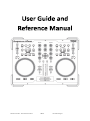
Professional Digital Producer
FEATURING
©American Audio® - www.americanaudio.eu
VMS2™
User Manual Page 1
©American Audio® - www.americanaudio.eu
VMS2™
User Manual Page 2
Please visit one of the following websites to view and download the VMS2™ MIDI table
chart:
www.americanaudio.us
www.americanaudio.eu
Please Note: All specifications and improvements to and in the design of this unit and this
manual are subject to change at any time without any prior written or published noticed.
6122 S. Eastern Ave
Los Angeles Ca. 90040
www.americanaudio.eu
©American Audio® - www.americanaudio.eu
VMS2™
User Manual Page 3
1. TABLE OF CONTENTS
1.
Table of Contents ................................................................................................................ 4
2.
Electrical Safety Precautions ............................................................................................... 6
3.
Important Safety Precautions ............................................................................................. 8
4.
Further Safety Instructions ............................................................................................... 11
5.
Unpacking.......................................................................................................................... 13
6.
Introduction ...................................................................................................................... 14
6.1 Customer Support .......................................................................................................... 14
7.
Set-Up Precautions ........................................................................................................... 15
7.1 Operating Determinations ............................................................................................. 15
8.
Main Features ................................................................................................................... 16
9.
Minimum System Requirements ...................................................................................... 17
9.1 PC Requirements ............................................................................................................ 17
9.2 Mac Requirements ......................................................................................................... 17
10.
Set-Up ............................................................................................................................ 18
10.1 Checking the Contents ................................................................................................. 18
10.2 Installing the Units........................................................................................................ 18
10.3 Connections .................................................................................................................. 18
11.
Software and ASIO Driver Installation........................................................................... 19
12.
General Functions and Controls .................................................................................... 20
12.1 Player Front .................................................................................................................. 20
12.2 Front Panel ................................................................................................................... 24
12.3 Rear Panel..................................................................................................................... 25
13.
Audio Interface Mode ................................................................................................... 27
13.1 4 Out Mode .................................................................................................................. 27
14.
MIDI Latency Modes ..................................................................................................... 28
©American Audio® - www.americanaudio.eu
VMS2™
User Manual Page 4
15.
EQ Modes ...................................................................................................................... 29
16.
Firmware Update .......................................................................................................... 30
17.
Computer Connection ................................................................................................... 32
17.1 Connecting the VMS2™ to your PC .............................................................................. 32
18.
Setup.............................................................................................................................. 33
19.
Cleaning ......................................................................................................................... 34
20.
Crossfader Replacement ............................................................................................... 35
20.1 Replacing the Crossfader.............................................................................................. 35
21.
ROHS – A Contribution to the Conservation of Environment ....................................... 36
22.
WEEE – Waste of Electrical and Electronic Equipment ................................................. 37
23.
Specifications................................................................................................................. 38
©American Audio® - www.americanaudio.eu
VMS2™
User Manual Page 5
2. ELECTRICAL SAFETY PRECAUTIONS
The lightning flash with an arrow triangular symbol is intended to alert the
user to the presence of non-insulated “dangerous voltage” within the
product’s enclosure, and may be of sufficient magnitude to constitute a
risk of electric shock.
The exclamation point triangular symbol is intended to alert the user to
the presence of important operating and maintenance (servicing)
instructions in the user manual accompanying the unit.
CAUTION
RISK OF ELECTRIC SHOCK! DO NOT OPEN!
TO REDUCE THE RISK OF ELECTRIC SHOCK, DO NOT
REMOVE THE COVER RACK. THERE ARE NO USER
SERVICEABLE PARTS INSIDE. REFER SERVICE TO YOUR
AUTHORIZED AMERICAN AUDIO® SERVICE DEALER.
Please carefully read and understand the instructions in this manual
thoroughly before attempting to operate this unit. These instructions
contain important safety information regarding the use and maintenance
of this unit. Take special care to follow all warning symbols and labels
both on the unit and printed in this manual. Also, Please keep this
manual with the unit, for future reference.
CAUTION:
Handle the power supply cord carefully. Do not damage or deform; it may cause
electric shock or malfunction when used. Hold the plug attachment when removing
from wall outlet. Do not pull on the cord.
To avoid electric shock, do not open the top cover when the unit is plugged in. If
problems occur with the unit, call your local American Audio® dealer.
Do not place metal objects or spill liquid inside the unit. Electric shock or malfunction
may occur.
©American Audio® - www.americanaudio.eu
VMS2™
User Manual Page 6
CAUTION:
TO PREVENT ELECTRIC SHOCK DO NOT USE THIS
(POLARIZED) PLUG WITH AN EXTENSION CORD,
RECEPTACLE OR OTHER OUTLET UNLESS THE BLADES
CAN BE CAREFULLY INSERTED TO PREVENT BLADE
EXPOSURE!
CAUTION:
USE OF CONTROLS OR ADJUSTMENTS OTHER THAN THOSE SPECIFIED HEREIN MAY
RESULT IN HAZARDOUS RADIATION EXPOSURE.
THE DEVICE SHOULD NOT BE ADJUSTED OR REPAIRED BY ANYONE EXCEPT PROPERLY
QUALIFIED SERVICE PERSONNEL.
NOTE:
NOTE:
This unit may cause interference to radio and
television reception.
This device uses a semiconductor laser. It is
recommended for use in a room at the
following temperature: 41˚- 95˚F or 5˚C 35˚C.
WARNING:
TO PREVENT FIRE OR SHOCK HAZARD, DO NOT
EXPOSE THIS DEVICE TO WATER OR MOISTURE!
©American Audio® - www.americanaudio.eu
VMS2™
User Manual Page 7
3. IMPORTANT SAFETY PRECAUTIONS
Read Instructions – All the safety and operating instructions should be read before the
product is operated.
Retain Instructions – The safety and operating instructions should be retained for future
reference.
Heed Warnings – All warnings on the product and in the operating instructions should be
adhered to.
Follow Instructions – All operating and use instructions should be followed.
Cleaning – The product should be cleaned only with a polishing cloth or a soft dry cloth.
Never clean with furniture wax, benzine, insecticides or other volatile liquids since they may
corrode the cabinet.
Attachments – Do not use attachments not recommended by the product manufacturer as
they may cause hazards.
Water and Moisture – Do not use this product near water — for example, near a bathtub,
wash bowl, kitchen sink, or laundry tub, in a wet basement or near a swimming pool and the
like.
Accessories – Do not place this product on an unstable cart, stand, tripod, bracket, or table.
The product may fall, causing serious injury to a child or adult and serious damage to the
product. Use only with a cart, stand, tripod, bracket, or table recommended by the
manufacturer, or sold with the product. Any mounting of the product should follow the
manufacturer’s instructions, and should use a mounting accessory recommended by the
manufacturer.
Cart – A product and cart combination should be moved with care. Quick
stops, excessive force, and uneven surfaces may cause the product and cart
combination to overturn.
Ventilation – Slots and openings in the cabinet are provided for ventilation and to ensure
reliable operation of the product and to protect it from overheating, and these openings
must not be blocked or covered. The openings should never be blocked by placing the
product on a bed, sofa, rug, or other similar surface. This product should not be placed in a
built-in installation such as a bookcase or rack unless proper ventilation is provided or the
manufacturer’s instructions have been adhered to.
Power Sources – This product should be operated only from the type of power source
indicated on the marking label. If you are not sure of the type of power supply to your home,
consult your product dealer or local power company.
©American Audio® - www.americanaudio.eu
VMS2™
User Manual Page 8
Location – The appliance should be installed in a stable location.
Nonuse Periods – The power cord of the appliance should be unplugged from the outlet
when left unused for a long period of time.
Grounding or Polarization
If this product is equipped with a polarized alternating current line plug (a plug
having one blade wider than the other), it will fit into the outlet only one way. This is
a safety feature. If you are unable to insert the plug fully into the outlet, try reversing
the plug. If the plug should still fail to fit, contact your electrician to replace your
obsolete outlet. Do not defeat the safety purpose of the polarized plug.
If this product is equipped with a three-wire grounding type plug, a plug having a
third (grounding) pin, it will only fit into a grounding type power outlet. This is a
safety feature. If you are unable to insert the plug into the outlet, contact your
electrician to replace your obsolete outlet. Do not defeat the safety purpose of the
grounding type plug.
Outdoor Antenna Grounding – If an outside
antenna or cable system is connected to the
product, be sure the antenna or cable system is
grounded so as to provide some protection
against voltage surges and built-up static
charges.
Article 810 of the National Electrical Code,
ANSI/NFPA 70, provides information with
regard to proper grounding of the mast and
supporting structure, grounding of the lead-in
wire to an antenna discharge unit, size of grounding conductors, location of antennadischarge unit, connection to grounding electrodes, and requirements for the grounding
electrode. See Figure 1.
Power Cord Protection – Power-supply cords should be routed so that they are not likely to
be walked on or pinched by items placed upon or against them, paying particular attention
to cords at plugs, convenience receptacles, and the point where they exit from the product.
Lightning – For added protection for this product during a lightning storm, or when it is left
unattended and unused for long periods of time, unplug it from the wall outlet and
disconnect the antenna or cable system. This will prevent damage to the product due to
lightning and power-line surges.
Power Lines – An outside antenna system should not be located in the vicinity of overhead
power lines or other electric light or power circuits, or where it can fall into such power lines
©American Audio® - www.americanaudio.eu
VMS2™
User Manual Page 9
or circuits. When installing an outside antenna system, extreme care should be taken to
keep from touching such power lines or circuits as contact with them might be fatal.
Overloading – Do not overload wall outlets, extension cords, or integral convenience
receptacles as this can result in a risk of fire or electric shock.
Object and Liquid Entry – Never push objects of any kind into this product through openings
as they may touch dangerous voltage points or short-out parts that could result in a fire or
electric shock. Never spill liquid of any kind on the product.
Servicing – Do not attempt to service this product yourself as opening or removing covers
may expose you to dangerous voltage or other hazards. Refer all servicing to qualified
service personnel.
Damage Requiring Service – Unplug this product from the wall outlet and refer servicing to
qualified service personnel under the following conditions:
When the power supply cord or plug is damaged.
If liquid has been spilled, or objects have fallen into the product.
If the product has been exposed to rain or water.
If the product does not operate normally by following the operating instructions.
Adjust only those controls that are covered by the operating instructions as an
improper adjustment of other controls may result in damage and will often require
extensive work by a qualified technician to restore the product to its normal
operation.
If the product has been dropped or damaged in any way.
When the product exhibits a distinct change in performance - this indicates a need
for service.
Replacement Parts – When replacement parts are required, be sure the service technician
has used replacement parts specified by the manufacturer or have the same characteristics
as the original part. Unauthorized substitutions may result in fire, electric shock, or other
hazards.
Safety Check – Upon completion of any service or repairs to this product, ask the service
technician to perform safety checks to determine that the product is in proper operating
condition.
Wall or Ceiling Mounting – The product should not be mounted to a wall or ceiling.
Heat – The product should be situated away from heat sources such as radiators, heat
registers, stoves, or other products (including amplifiers) that produce heat.
©American Audio® - www.americanaudio.eu
VMS2™
User Manual Page 10
4. FURTHER SAFETY INSTRUCTIONS
Read Instructions – All the safety and operating instructions should be read before the unit
is operated. The safety and operating instructions should be saved for future reference.
Heed Warnings – All warnings on the unit and in the operating instructions should be
adhered to.
Water and Moisture – The device should not be used near water - for example, near a bath
tub, kitchen sink, laundry tub, in a wet basement or near a swimming pool, etc.
Ventilation – The device should be situated so that its location or position does not interfere
with its proper ventilation. For example, the device should not be situated on a bed, sofa,
rug, or similar surface that may block the ventilation openings; or, placed in a built-in
installation, such as a bookcase or cabinet that may impede the flow of air through the
ventilation openings.
Heat – The device should be situated away from heat sources such as radiators, heat
registers, stoves, or other appliances (including amplifiers) that produce heat.
Power Sources – The device should be connected to a power supply only of the type
described in the operating instructions or as marked on the unit.
Servicing – The user should not attempt to service the device beyond that described in the
operating instructions. All other servicing should be referred to qualified service personnel.
The device should be serviced by qualified service personnel when:
The power-supply cord or the plug has been damaged.
Objects have fallen, or liquid has been spilled into the unit.
The unit has been exposed to rain or water.
The unit does not appear to operate normally or exhibits a marked change in
performance.
©American Audio® - www.americanaudio.eu
VMS2™
User Manual Page 11
The serial and model number for this unit is located on the rear panel. Please write down the
numbers here and retain for future reference.
Model No.
____________________________________________________________
Serial No.
____________________________________________________________
Purchase Notes ____________________________________________________________
Date of Purchase ____________________________________________________________
Dealer Name
____________________________________________________________
Dealer Address _____________________________________________________________
___________________________________________________________________________
___________________________________________________________________________
Dealer Phone
______________________________________________________________
©American Audio® - www.americanaudio.eu
VMS2™
User Manual Page 12
5. UNPACKING
Every VMS2™ has been thoroughly tested and has been shipped in perfect operating
condition.
Carefully check the shipping carton for damage that may have occurred during shipping.
If the carton appears to be damaged, carefully inspect your device for any damage and be
sure all equipment necessary to operate the device has arrived intact.
In case damage has been found or parts are missing, please contact our toll free customer
support number for further instructions.
Please do not return the device to your dealer.
©American Audio® - www.americanaudio.eu
VMS2™
User Manual Page 13
6. INTRODUCTION
Congratulations and thank you for purchasing the American Audio® VMS2™ media
controller. This device is a representation of American Audio’s® continuing commitment to
produce the best and highest quality audio products possible at an affordable price.
Please read and understand this manual completely before attempting to operate your new
device. This booklet contains important information concerning the proper and safe
operation of your new device.
6.1 CUSTOMER SUPPORT
American Audio® provides a toll free customer support line to provide set up help and to
answer any questions, should you encounter problems during your initial set-up or
operation. You may also visit us on the web at www.AmericanAudio.us for any comments or
suggestions.
Service Hours are Monday through Friday 08:30 to 17:00 GMT+1.
Voice: 0031 45 546 85 30
Fax: 0031 45 546 85 99
E-mail: [email protected]
For spare parts please look in our online part shop.
Caution!
There are no user serviceable parts inside this device. Do not attempt any repairs by yourself.
Doing so will void your manufactures warranty. In the unlikely event your device may require
service, please contact American Audio® customer support.
Do not discard the packing carton in the trash. Please recycle whenever possible.
©American Audio® - www.americanaudio.eu
VMS2™
User Manual Page 14
7. SET-UP PRECAUTIONS
Please be sure to make any connections before plugging the device in to an electrical outlet.
All fader and volume controls should be set to zero or minimum position, before the device is
switched on.
If the device has been exposed to drastic temperature fluctuation (e.g. after transportation), do
not switch on the device immediately. The arising condensation of water might damage your
device. Leave the device switched off until it has reached room temperature.
7.1 OPERATING DETERMINATIONS
When installing this device, please make sure that it is not exposed to extreme heat,
moisture or dust!
Do not operate the mixer in extremely hot (more than 40°C / 104°F) or extremely cold
(less than 5°C / 40°F) surroundings.
Keep the unit out of direct sunlight and away from heaters.
Operate the device only after becoming familiar with its functions. Do not permit
operation by persons not qualified for operating the unit. Most damages are the result
of unprofessional operation!
©American Audio® - www.americanaudio.eu
VMS2™
User Manual Page 15
8. MAIN FEATURES
3 Cue Points Per Side
2-Channel Mixer w/ Volume Faders
MIDI Control via USB
Stereo Master and Booth Outputs
Built-In 4 In 4 Out
Mic
Seamless Loop (uninterrupted loop
playback)
Master Volume Control
Full EQ on 2 MIDILOG Channels
Track & Deck Selectors
Crossfader Assign, Curve, & Reverse
Durable Touch Sensitive High-Res Jog
Wheel
Pitch Lock
One Mic Combo Jack
Pitch Bend
Innofader Compatible
82 MIDI Controls
USB/Analog Source Selects on Each
MIDILOG ™ Channel
©American Audio® - www.americanaudio.eu
VMS2™
User Manual Page 16
9. MINIMUM SYSTEM REQUIREMENTS
Note: System Requirements may differ due to manufacturer software!
9.1 PC REQUIREMENTS
Windows XP SP2 or Windows Vista (32-bit & 64-bit supported)
PIV 1.2GHz Computer (SSE2 CPU), AMD 64 or Greater
1024_768 SVGA Video
2 GIG RAM (Vista)
40MB Free on the Hard-Drive (Recommended 2000MB)
DirectX 9.0
9.2 MAC REQUIREMENTS
Mac OS X 10.5 PPC/Intel, 10.5.6 Intel, or 10.6 Intel
1.86GHz
2GB RAM
©American Audio® - www.americanaudio.eu
VMS2™
User Manual Page 17
10. SET-UP
10.1 CHECKING THE CONTENTS
Be sure your VMS2™ was shipped with the following:
VMS2™ Controller
Operating Instructions (This Booklet)
USB Cable
6V Power Adapter
Virtual DJ Software
Warranty card
10.2 INSTALLING THE UNITS
Place your unit on a flat surface or mount it in a secure rack mount case.
Be sure the player is mounted in a well-ventilated area where it will not be exposed to
direct sunlight, high temperatures, or high humidity.
Try to place the unit as far as possible from TVs and tuners, as the unit may cause
undesirable interference.
10.3 CONNECTIONS
Be sure main power is connected last to prevent any electrical damage.
AUDIO CONNECTIONS
Use RCA or XLR cables to connect the VMS2™ outputs to powered speakers or an amplifier.
Never connect this player's output to a mixers Phono inputs.
Caution: To avoid severe damage to the unit, be sure the power is off when making
connections to the unit.
©American Audio® - www.americanaudio.eu
VMS2™
User Manual Page 18
11. SOFTWARE AND ASIO DRIVER INSTALLATION
Insert the disc into your computer cd drive and click on the CD icon.
Depending on the type of computer you are operating, choose the *.exe file for PC or the
*.dmg file for MAC.
Choose your desired language and
click OK.
Read the following information and
click Next.
Follow the screen prompts to install
the software.
The ASIO Driver installation will open
during the Virtual DJ installation.
PC users, follow the screen
prompts for proper installation.
Mac install is automatic after
clicking on the *.dmg file.
©American Audio® - www.americanaudio.eu
VMS2™
User Manual Page 19
12. GENERAL FUNCTIONS AND CONTROLS
12.1 PLAYER FRONT
(1) Sync Button – Use this button to set this deck to master and auto sync the other deck's
tempo to the master.
(2) Bank Buttons – These buttons are used to store 3 cue points.
(3) Cue Button – These buttons are used to activate a channels‘ Cue mode. The Cue LED will
glow when a channels‘ Cue mode is activated. The Cue function sends a channels‘ incoming
signal to the headphones. The cue level is adjusted by the Cue Level Knob.
©American Audio® - www.americanaudio.eu
VMS2™
User Manual Page 20
Note: The MIDILOG Cue button has an additional function. During power-on, hold this button
down to toggle the Post EQ Mode on and off. For more on this, please refer to the Virtual DJ
Setup described in chapter 11 (Software and ASIO Driver Installation).
(4) Navigation Buttons – These buttons allow easy navigation of your music library on your
software.
(5) Master Volume and Booth Controls
Master Volume Control – This knob is used to control the master output level. To avoid
distorted output, try to maintain an average output signal level no greater than +4dB.
To avoid speaker damage that may be caused by excessive volume, be sure this knob is
always set to zero (completely down) before turning the unit on.
Booth Level – This knob is used to adjust the monitor volume output level. Turn the
knob in a clockwise direction to increase the monitor volume.
(6) MIDILOG Mixer Section
Channel Gain Control – This adjustment is used to adjust the audio source signal input gain
for a channel. Never use the gain control to adjust a channels output volume. Setting the
gain level properly will ensure a clean output signal. An improper gain level adjustment will
send a distorted signal throughout the entire audio line which may damage speakers and
amplifiers. To properly set a channels gain level control:
1. Be sure the Master Volume Control is set to level 4.
2. Set the Channel Fader to level 8.
3. Begin playback on an audio source connected to the channel you are adjusting.
4. Use the Gain Control to adjust an average output volume of +4 dB.
5. Repeat this step for all channels
Channel Treble Control – This knob is used to adjust the treble levels of a channel allowing
for a maximum treble gain of +6dB or maximum decrease of -100dB. Turning the knob in a
counter-clockwise direction will decrease the amount of treble applied to a channel signal,
turning the knob in a clockwise direction will increase the amount of treble applied to a
channel signal.
Channel Midrange Control – This knob is used to adjust the midrange levels of a channel
allowing for a maximum midrange gain of +6dB or maximum decrease of -100dB. Turning
the knob in a counter-clockwise direction will decrease the amount of midrange applied to a
channel signal, turning the knob in a clockwise direction will increase the amount of
midrange applied to a channel signal.
©American Audio® - www.americanaudio.eu
VMS2™
User Manual Page 21
Channel Bass Control – This knob is used to adjust the low frequency levels of a channel
allowing for a maximum bass gain of +6dB or maximum signal decrease of -100dB. Turning
the knob in a counter-clockwise direction will decrease the amount of bass applied to a
channel signal, turning the knob in a clockwise direction will increase the amount of bass
applied to a channel signal.
(7) IN, OUT, Reloop, & Loop Buttons
IN Button – “Cue On The Fly” - This function allows you to set a Cue Point without
music interruption (“on the fly”). This button also sets the starting point of a seamless
loop.
OUT Button – This button is used to set the ending point of a loop. A loop is started by
pressing the IN Button, pressing the OUT Button sets the loop ending point. The loop
will continue to play until the Out Button is pressed once again.
Reloop Button – If a seamless loop has been made, but the player is not actively in
seamless loop mode (a loop is not playing), pressing the Reloop Button will instantly
reactivate the seamless loop mode. To exit loop, press the Out Button.
(8) Search Buttons
This search button allows you to quickly scan backwards through a track.
This search button allows you to quickly scan forwards through a track.
(9) Vinyl – Pushing this button activates Vinyl mode.
(10) Load Buttons – These buttons are used to load the selected song to the assigned deck in
the software.
(11) Channel Fader – These faders are used to control the output signal of any source
assigned to its particular channel.
(12) Crossfader – This fader is used to blend the output signals of channels A and B together.
When the fader is in the full left position (channel A), the output signal of channel A will be
controlled by the master volume level. The same fundamentals will apply for channel B.
Sliding the fader from one position to another will vary the output signals of channels A and
B respectively. When the crossfader is set in the center position, the output signals of both
the channels A and channels B will be even.
(13) Channel Volume Level Indicators – The LED indicators that run along each channels EQ
section are used to measure incoming signal levels. Use these indicators to visually maintain
an average signal output of +4dB. A consistent average output level of +4dB will produce a
clean output signal. When no Cue sources are selected, these indicate the volume level on
the Master Output. When one or more Cue sources are selected, these indicate the volume
levels on all of the Cue sources combined. At power-on, these indicate the VMS2™ firmware
©American Audio® - www.americanaudio.eu
VMS2™
User Manual Page 22
version. If the left side lights up 1 LED, and the right side lights up 3 LEDs, the firmware
version is 1.3.
(14) Pause Button – Press this button to pause whatever music source is playing.
(15) Play Button – Press this button to play your desired music source.
(16) CUE – Pressing the CUE button during playback immediately pauses playback and
returns the track to the last set cue point. The red CUE LED will glow when the unit is in cue
mode. The LED will also flash every time a new Cue Point is set. The CUE button can be held
down to momentarily play the track. When you release the CUE button, it instantly returns
to the Cue Point. You can also tap the CUE button to create a „Bop Effect“.
(17) Jog Wheel – This wheel has three functions:
Attention: Make sure that nothing is touching or resting on the jog wheels when you power
on the VMS2™.
The wheel works as a pitch bend during playback. Turning the wheel clockwise can
increase the pitch percentage up to 100%, and turning the wheel in the counterclockwise direction can decrease the pitch percentage down to -100%. The pitch bend
will be determined on how long you turn the jog wheel continuously.
The jog wheel also controls the scratch effect, when the scratch effect is active.
The jog wheel can also serve as frame search.
Note: The inside of the wheel is touch sensitive and the outside edge of the wheel is not.
Example: You can scratch by touching the inside or center of the wheel, and pitch bend when
you touch the outside edge of the wheel.
(18) Pitch Bend Buttons
(-) Pitch Bend Button – The (-) pitch bend function creates a momentary “Slow Down” in the
BPM’s (Beats per minute) while it is playing. This will allow you to match the beats between
two playing audio sources. Remember, this is a momentary function. When you remove your
finger from the pitch button, the BPM’s will automatically return to the Pitch slider's pitch
value. Holding down this button will give a maximum of -100% pitch. Use this function to
slow to another playing music source. Be sure to notice that this function is a momentary
pitch adjustment, for a more precise adjustment use the Pitch Slider (20) to match the BPM’s
with another playing music source.
(+) Pitch Bend Button – The (+) pitch bend function creates a momentary “Bump” in the
BPM’s (Beats per minute) while it is playing. This will allow you to match the beats between
two playing audio sources. Remember, this is a momentary function. When you remove your
finger from this button, the BPM’s will automatically return to the Pitch slider's selected
pitch. Holding down this button will give a maximum of +100% pitch.
©American Audio® - www.americanaudio.eu
VMS2™
User Manual Page 23
(19) Shift – Enables secondary MIDI commands on buttons and jog wheels. Example: Press
Shift and Vinyl to activate Keylock.
(20) Pitch Slider – This slider is used to adjust the playback pitch percentage. The slider is a
set adjustment and will remain set until the pitch slider is moved or the pitch function has
been turned off.
12.2 FRONT PANEL
MIC SECTION (21-23)
The VMS2™ is equipped with a microphone input, easy to use, no ASIO routing required. The
microphone channel has an independent On/Off switch, Gain control, and Tone control.
(21) Mic On/Off – Turns the microphone on and off. When your microphone is on, the
button will be backlit by a red LED.
(22) Mic Gain Control – Increase or decrease the microphone signal level.
(23) Mic Tone – Adjust the vocal tone on the microphone input.
MIXER CONTROLS (24-25)
The VMS2™ can be used as a MIDI control, a standalone mixer, or in combination giving you
maximum control of your music collection whether it be on vinyl, digital CD's or Computer DJ
software (Virtual DJ included).
(24) USB/Analog Switch – These will switch the corresponding channel from USB audio
stream or analog audio input. USB will route the software assigned ASIO audio channel thru
the corresponding MIDILOG channel. Analog will route the analog audio input from the rear
panel thru the corresponding MIDILOG channel.
(25) Normal/Reverse (Crossfader Mode) – Switches the crossfader from normal to reverse
mode. In reverse mode the CF A assignments will be on the right of the crossfader and the
CF B on the left.
(26) Cue/Master Knob – Sets the headphones output from Cue or Master. When set to the
Cue position, the headphones will receive the signal from any and all channels with the Cue
button activated. When set to the Master position, the headphones will receive the pre
©American Audio® - www.americanaudio.eu
VMS2™
User Manual Page 24
fader master output signal, allowing you to cue the master at any output level and even if it
is fully off. Any knob settings in between Cue and Master will blend the Cue and Master
signals.
(27) Headphones Gain – Will set the output level of the headphones.
(28) Headphones Jack – Connect your headphones to this jack. The headphones signal is
controlled by the controls described previously.
(29) Curve Knob – This knob will adjust the curve of the crossfader from mix curve, dipped
curve, to scratch curve.
12.3 REAR PANEL
(30) Power Switch – This switch will turn the VMS2™ on and off. When the unit is powered
on, the power indicator LED will glow. Attention: Make sure that nothing is touching or
resting on the jog wheels when you power on the VMS2™.
(31) XLR Balanced Outputs – The VMS2™ has RCA (unbalanced) and XLR (balanced) connections to connect to amplifiers or connect directly to powered speakers. It is highly
recommended that the XLR outputs are used for any connection of more than 20ft. Never
connect the XLR outputs and the RCA master outputs at the same time; this may affect your
output. To set your desired volume, use the Master Volume (5) knob.
(32) Booth Outputs – The VMS2™ offers a secondary output usually used to monitor your
mix or to route to an outboard recording device. This output has an independent volume
control, the Booth (5) knob.
(33) RCA Outputs – The VMS2™ has RCA (unbalanced) and XLR (balanced) connections to
connect to amplifiers or connect directly to powered speakers. It is highly recommended
that the XLR outputs are used for any connection of more than 20ft. Never connect the XLR
outputs and the RCA outputs at the same time; this may affect your output. To set your
desired volume, use the Master Volume (5) knob.
(34) RCA Inputs – RCA connectors for CD players, turntables, and other analog inputs.
©American Audio® - www.americanaudio.eu
VMS2™
User Manual Page 25
MIDILOG 1 & 2: Phono/Line level RCA inputs are used to connect turntables, CD
players, MP3 players, or other line level sources. The type of input must directly reflect
the selected mode of the Line/Phono Selector Switch. Turntables equipped with MM
pickup cartridges (All DJ turntables use MM pickup cartridges) may be connected to
these jacks as long as the Line/Phono Selector Switch is in the Phono position. CD
players, MP3 players, and other line level instruments may only be connected to these
jacks as long as the Line/Phono Selector Switch is in the Line position.
(35) Phono Ground – Be sure to connect turntable ground leads to either or both of the two
available ground terminals. This will reduce the humming and popping noises associated
with magnetic phono cartridges.
(36) MIC – XLR and 1/4" combo jack for microphone connection. The volume output level for
the microphone will be controlled by its own respective volume knob.
(37) Line/Phono Selector Switches – These switches are used to change the voltage line
levels of their respective Line/Phono RCA inputs jacks. When connecting turntables with
magnetic cartridges to these jacks, be sure the corresponding switch is in the Phono
position; and when using line level input devices be sure this switch is in the Line position.
(38) USB Port – Connect here to your PC for MIDI interface and USB interface (audio ins and
outs).
(39) Power Supply – The power supply is not required, but the headphones may be
underpowered, and there is an increased chance of audio distortion.
©American Audio® - www.americanaudio.eu
VMS2™
User Manual Page 26
13. AUDIO INTERFACE MODE
13.1 4 OUT MODE
The VMS2™ can act like a 4x4
audio interface. Your USB audio
is routed through the VMS2™'s
MIDILOG Ch. #1 and #2 inputs.
If you wish to route the inputs
via USB for software play
through or Timecode control,
set your desired VMS2™
Channel to the USB setting and
the channels' Line/Phono
Selector Switch (37) to the
correct setting.
Note: For the best performance,
if no inputs are in use, set the
Inputs to Disabled by clicking on
the ASIO Driver Interface.
Your inputs and outputs can be
set to channels 1-8, but your
software may not support the
ASIO stream of the channel
numbers.
Check the software manual to
make sure it does.
©American Audio® - www.americanaudio.eu
VMS2™
User Manual Page 27
14. MIDI LATENCY MODES
There are two MIDI latency modes; Normal mode and Turbo mode. Normal mode has a MIDI
latency of 10 milliseconds, this is the default mode. Turbo mode has a MIDI latency of 1
millisecond.
To set the VMS2™ to Turbo mode, do as follows:
Before powering on, press and hold the Cue, Play, and Pause buttons on the left side.
Hold the buttons until the Channel Volume Level Indicators (13) light up with the code
version. Read more about the firmware version in chapter 12.1 Player Front (under 13 Channel Volume Level Indicators).
It is recommended that you use the default mode if your computer does not meet the
recommended system requirements or if you are using Windows Vista. It is also strongly
recommended that you close all programs running in the background; this will free up RAM
and minimize the CPU process. If you are using a laptop, turn off your wireless card if
possible, since this may cause sound problems. Allow your computer’s hard drive to have at
least 20% free space.
©American Audio® - www.americanaudio.eu
VMS2™
User Manual Page 28
15. EQ MODES
The EQ for the USB audio can work in
two different modes, Pre & Post EQ.
These EQ modes work in the 4 out
interface mode that is described in
chapter 13.1 4 Out Mode.
In Pre EQ, the USB audio signal is
affected by the VMS2™ EQ. Pre EQ is
the default EQ. In Pre EQ mode the
ASIO Driver will list the VMS2™ device
number; the first number in the
sequence will be a "0" (See picture).
Note: Beware that mapping the MIDI on the EQ knobs in this mode will cause your audio to
process the EQ from the software and VMS2™ EQ.
Post EQ is for users who prefer using
the EQ from their software. To toggle
the Post EQ mode on and off, do as
follows:
Before powering up the VMS2™,
press and hold the Forward
Search Button (8) on deck 2 and
then power on the unit.
Release the button - your
computer may reinstall the
VMS2™ as a new device, please
allow 10-20 seconds for the
change to take place.
Confirm the EQ change by checking the ASIO Driver configuration. The first number in the
sequence will be a "1" in this mode (See picture).
Note: Make sure you are using software where you can map the MIDI from the EQ and that
the EQ has been mapped when using this mode.
©American Audio® - www.americanaudio.eu
VMS2™
User Manual Page 29
16. FIRMWARE UPDATE
The included version of Virtual DJ includes a
Firmware update utility. It is necessary to
install this. To update your VMS2™:
Please check your computer audio
settings and ensure that the VMS2™ is
not set as a default playback, playback
recording, or MIDI device. This will
interfere with the update and software
applications.
Click Start Menu > All Programs >
Virtual DJ > FIRMWARE Update.
Select the VMS2™ or USB Audio Device
(Windows XP). Load the update file by
clicking browse and going to the file
location.
Wait until the bar is filled in completely
and "Upgrade Complete" is displayed.
Unplug the USB and shut down the
VMS2™.
©American Audio® - www.americanaudio.eu
VMS2™
User Manual Page 30
You may receive some Error windows like you see below.
Select the proper device in device select window.
Please check your computer audio setting and
ensure that the VMS2™ is not set as a default
playback, playback recording, or MIDI device. This
will interfere with the update and software
applications. Also, make sure that any software
that uses MIDI or the Audio interface is closed.
©American Audio® - www.americanaudio.eu
VMS2™
User Manual Page 31
17. COMPUTER CONNECTION
17.1 CONNECTING THE VMS2™ TO YOUR PC
Connect the VMS2™ to your PC by using the USB ports located on the rear of the VMS2™
and your PC. Connect the supplied USB cable to the USB port on the rear of the VMS2™, and
the other end connects to the USB port on your computer.
Note: Before connecting your VMS2™ to your computer or laptop, we highly recommend that
you install the provided software. The Virtual DJ version included with this product is specifically tailored to work with the VMS2™ with no setup required. The setup of other non-factory
authorized drivers and software is far more complex and in some instances not as reliable.
©American Audio® - www.americanaudio.eu
VMS2™
User Manual Page 32
18. SETUP
©American Audio® - www.americanaudio.eu
VMS2™
User Manual Page 33
19. CLEANING
Due to fog residue, smoke, and dust, cleaning the mixer should be carried out periodically to
residue build up.
Use normal glass cleaner and a soft cloth to wipe down the outside casing.
Use a cleaner specially designed for electronics to spray in and around the knobs and
switch. This will reduce small particle built up that can affect the proper operation of
the device.
Cleaning should be carried out every 30-60 days to prevent heavy built up.
Always be sure to dry all parts completely before plugging the device in.
Cleaning frequency depends on the environment in which the device operates (i.e. smoke,
fog residue, dust, dew).
©American Audio® - www.americanaudio.eu
VMS2™
User Manual Page 34
20. CROSSFADER REPLACEMENT
The crossfader is “Hot Swappable” which
means it may be replaced at any time, even
when power is applied.
Replace with American Audio VMS2™
crossfader (part# Z-FF-8).
If you wish to upgrade to an Innofader, please
order the Innofader model which comes with
the VMS2™ plate cover to protect the
Innofader from damage during handling of the
VMS2™. If you upgrade to the Innofader,
please make sure the power is off before
upgrading to limit the chance of damage to
the Innofader and/or VMS2™ during
installation.
Replacing with any other model fader may seriously damage your mixer.
20.1 REPLACING THE CROSSFADER
1. Disconnect the mixers main power supply.
2. Using a Phillips screw driver, unscrew the two outside screws on each side that hold the
cross fader assembly in place.
3. Gently remove the crossfader assembly from its seated position. You may need to
wiggle the crossfader slightly to remove it.
4. After removing the crossfader assembly, disconnect the ribbon cable that attaches the
cross fader to the PC board. Grasp the crossfader by its base and pull the ribbon cable
by its connector not the actual cables. The connector is designed to only fit one way, so
don’t worry about the connector’s orientation.
5. Unscrew the two inner screws that connect the crossfader to the crossfader plate.
6. Connect the new crossfader to the ribbon cable and replace in reverse order.
Note: For Innofader installation instructions please visit:
http://innofader.com/mixers.php?id=75
©American Audio® - www.americanaudio.eu
VMS2™
User Manual Page 35
21. ROHS – A CONTRIBUTION TO THE CONSERVATION OF ENVIRONMENT
The European Union has adopted a directive on the restriction/prohibition of the use of
hazardous substances. This directive, referred to as ROHS, is a frequently discussed topic in
the electronic industry.
It restricts, among other things, six materials: Lead (Pb), Mercury (Hg), Hexavalent Chromium
(CR VI), Cadmium (Cd), Polybrimated Biphenyls as flame retardant (PBB), Polybrominated
Diphenyl, also a flame retardant (PBDE). The directive applies to nearly all electronic and
electrical devices whose mode of operation involves electric or electromagnetic fields – in
short: each kind of electronics we have around us in our households or at work.
As manufacturers of products of the brands of AMERICAN AUDIO®, AMERICAN DJ®, ELATION
Professional and ACCLAIM Lighting, we are obligated to comply with the ROHS directive.
Therefore, as early as two years prior to the directive coming into force, we started our
search for alternative environmentally friendly materials and manufacturing processes.
Well before the ROHS directive took effect, all of our products were manufactured meeting
the standards of the European Union. With regular audits and material tests we can still
assure that the components we use are always ROHS-compliant and that the manufacturing
process, as far as the state of technology allows, is environmentally friendly.
The ROHS directive is an important step to the protection of our environment. We, as
manufactures, feel obligated to make our contribution in this respect.
©American Audio® - www.americanaudio.eu
VMS2™
User Manual Page 36
22. WEEE – WASTE OF ELECTRICAL AND ELECTRONIC EQUIPMENT
Every year thousands of tons of electronic components, which are harmful to the
environment, end up at the waste disposals around the world. To ensure the best possible
disposal or recovery of electronic components, the European Union has adopted the WEEE
directive.
The WEEE-system (Waste of Electrical and Electronic Equipment) can be compared with the
system of the “Green Spot”, which has been in use for several years. The manufactures have
to make their contribution to the utilization of waste at the time they release the product.
Money resources obtained by doing so will be applied to develop a common system of waste
management. Thereby we can ensure professional and environmentally friendly scraping
and recycling program.
As manufactures, we are part of the German system of EAR and we make our contribution
towards it.
(Registration in Germany: DE41027552)
That means that products of AMERICAN DJ® and AMERICAN AUDIO® can be left in the
collection points free of charge and they will be used in the recycling program. Products of
ELATION Professional, which are used only by professionals, shall be handled by us. Please
send Elation products directly to us at the end of their lifetime so that we can professionally
dispose of them.
Like the above ROHS, the WEEE directive is an important contribution to the environment
protection and we are glad to help to clean the environment with this disposal system.
We are happy to answer any of your inquiries and welcome your suggestions at:
[email protected]
©American Audio® - www.americanaudio.eu
VMS2™
User Manual Page 37
23. SPECIFICATIONS
Model:
American Audio® VMS2™ - PC Media Controller
Dimensions:
399 (L) x 300 (W) x 40 (H) mm
15.7" (L) x 12 (W) x 1.5" (H)
Installation:
Place on flat surface or mount in flat case
Weight:
10,9 Lbs. / 4,93 Kg
Power supply:
DC 6V Single Voltage
AC 100V, 50/60Hz (Japan)
AC 110V, 60Hz (Colombia)
AC 120V, 60Hz (U.S.A. and Canada)
AC 127V, 60Hz (Mexico)
AC 220V, 50Hz (Chile and Argentina)
AC 220V, 60Hz (Philippines and Korea)
AC 230V, 50Hz (Europe, New Zealand, South Africa, Singapore)
AC 240V, 50Hz (Australia and U.K.)
Power Consumption:
6W
Environ. Conditions:
Operating Temperature: 5 to 35°C
Humidity: 25 to 85% RH (non-condensing)
Storage Temperature: -20 to 60˚C
Accessories:
USB 2.0 Cable
Switching Adaptor
ITEM
NORMAL
LIMIT
CONDITION
Gain Max, EQ Flat
5V +/-0.5dB
5V +/-1dB
Line & Mixed Out
5.5V +/-0.5dB
5.5V +/-1dB
1KHz, 0dB
Phones
2V
1,8V
1KHz, -20dB
Output Level
©American Audio® - www.americanaudio.eu
VMS2™
User Manual Page 38
Channel Balance (From 0 to -40db For Mixed Out)
Line
Within 0,5dB
Mixed Out
Within 1dB
L/R Separation
Line
97dB
85dB
1KHz, 0dB
Mixed Out
95dB
85dB
1KHz, 0dB (Max. Out,
EQ Flat)
Line
0,025%
0,03%
1KHz, 0dB
Mixed Out
0,025%
0,03%
1KHz, 0dB (Max. Out,
EQ Flat)
Phones
0,045%
0,03%
1KHz, 0dB (1V
Output)
Line
97dB
85dB
1KHz, 0dB
Mixed Out
97dB
85dB
1KHz, 0dB (Max. Out,
EQ Flat)
T.H.D. + NOISE
S/N Ratio
Dynamic Range (Max. Output, EQ Flat)
Line
96dB
85dB
1KHz,-60dB
Mixed Out
94dB
85dB
1KHz,-60dB
Line
10-20KHz +/-0,3dB
10-20KHz +/-1dB
Mixed Out
10-20KHz +/-0,3dB
10-20KHz +/-1dB
2V
1,8V
Frequency Response
Phones
Max. Output
©American Audio® - www.americanaudio.eu
VMS2™
1KHz, 0dB, THD=1%
User Manual Page 39
NOTES:
Specifications and improvements in the design of this unit and this manual are subject to
change without any prior written notice.
CHECK THE AMERICAN AUDIO WEBSITE FOR DOWNLOADABLE USER SOFTWARE UPDATES.
©American Audio® World Headquarters
6122 S. Eastern Ave.
Los Angeles, CA 90040 USA
Tel: 323-582-3322
Fax: 323-582-3311
www.americanaudio.us
[email protected]
American DJ Europe
Junostraat 2
6468 EW Kerkrade
Netherlands
Tel: +31 45 546 85 00
Fax: +31 45 546 85 99
www.americandj.eu
[email protected]
©American Audio® - www.americanaudio.eu
VMS2™
User Manual Page 40