1
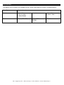
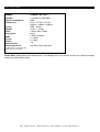
X-MOVE LED PLUS
User Instructions
A.D.J. Supply Europe B.V.
Junostraat 2
6468 EW Kerkrade
The Netherlands
www.americandj.eu
Rev. 6/08
Contents
GENERAL INFORMATION ........................................................................................................................................................ 3
GENERAL INSTRUCTIONS ........................................................................................................................................................ 3
FEATURES ................................................................................................................................................................................ 3
HANDLING PRECAUTIONS....................................................................................................................................................... 3
SAFETY PRECAUTIONS ............................................................................................................................................................ 4
SET UP ..................................................................................................................................................................................... 4
SYSTEM MENU CHART ............................................................................................................................................................ 7
SYSTEM MENU ........................................................................................................................................................................ 8
OPERATION ........................................................................................................................................................................... 10
UC3 CONTROL ....................................................................................................................................................................... 11
DMX TRAITS ......................................................................................................................................................................... 12
FUSE REPLACEMENT ............................................................................................................................................................. 13
CLEANING.............................................................................................................................................................................. 13
TROUBLE SHOOTING............................................................................................................................................................. 13
SPECIFICATIONS .................................................................................................................................................................... 14
ROHS and WEEE .................................................................................................................................................................. 15
A.D.J. Supply Europe B.V. – www.americandj.eu – X-Move LED Plus™ Instruction Manual Page 2
INTRODUCTION
GENERAL INFORMATION
Unpacking: Thank you for purchasing the X-Move LED Plus™ by American DJ ® . Every X-Move LED Plus™
has been thoroughly tested and has been shipped in perfect operating condition. Carefully check the shipping carton for damage that may have occurred during shipping. If the carton appears to be damaged,
carefully inspect your fixture for any damage and be sure all equipment necessary to operate the unit has
arrived intact. In the event damage has been found or parts are missing, please contact our toll free customer
support number for further instructions. Please do not return this unit to your dealer without contacting
customer support first.
Introduction: The X-Move LED Plus is a eight channel DMX intelligent , moving head, mini LED fixture. The XMove LED Plus™ can operate as a stand lone fixture or in a Master/Slave configuration. The X-Move LED
Plus™ has three operating modes; a sound active, show mode, DMX controlled. For best results use fog or
special effects smoke to enhance the beams projections. The X-Move LED Plus offers new advanced high
performance light source – 30% brighter than the original X-Move LED 20W LED source
Customer Support: If you encounter any problems, please contact your trusted American Audio shop.
We also offer the possibility, to contact us directly: You can contact us via our website www.americandj.eu or
via email: www.americandj.eu
Warning! To prevent or reduce the risk of electrical shock or fire, do not expose this unit to rain or moisture.
Warning! This may cause severe eye damage. Avoid looking directly into the light source at all times!.
GENERAL INSTRUCTIONS
To optimize the performance of this product, please read these operating instructions carefully to familiarize
yourself with the basic operations of this unit. These instructions contain important safety information regarding
the use and maintenance of this unit. Please keep this manual with the unit, for future reference.
FEATURES
• DMX-512 Protocol Compatible (Eight DMX Channels)
• RGB + White
• 3 Operating Modes - Sound Active, Show Mode, & DMX Control
• Internal Microphone
• Digital Display for Address and Function Setting
• UC3 Controller (Not Included)
• 4 Preprogrammed Shows
HANDLING PRECAUTIONS
Caution! There are no user serviceable parts inside this unit. Do not attempt any repairs yourself, doing so
will void your manufactures warranty. In the unlikely event your unit may require service please contact
American DJ®.
During operation the housing may become extremely hot. Avoid touching the unit with bare hands while in use.
American DJ® will not accept any liability for any resulting damages caused by the non-observance of this
manual or any unauthorized modification to this unit.
A.D.J. Supply Europe B.V. – www.americandj.eu – X-Move LED Plus™ Instruction Manual Page 3
SAFETY PRECAUTIONS
For Your Own Personal Safety, Please Read and Understand This Manual Completely Before You
Attempt To Install Or Operate This Unit!
• To reduce the risk of electrical shock or fire, do not expose this unit rain or moisture
• Do not spill water or other liquids into or on to your unit.
• Be sure that the local power outlet match that of the required voltage for your unit.
• Do not attempt to operate this unit if the power cord has been
frayed or broken.
• Do not attempt to remove or break off the ground prong from the electrical cord. This prong is used to reduce
the risk of electrical shock and fire in case of an internal short.
• Disconnect from main power before making any type of connection.
• Do not remove the cover under any conditions. There are no user serviceable parts inside.
• Never operate this unit when it’s cover is removed.
• Always be sure to mount this unit in an area that will allow proper ventilation. Allow about 6” (15cm) between
this device and a wall.
• Do not attempt to operate this unit, if it becomes damaged.
• This unit is intended for indoor use only, use of this product outdoors voids all warranties.
• Always mount this unit in safe and stable matter.
• Power-supply cords should be routed so that they are not likely to be walked on or pinched by items placed
upon or against them, paying particular attention to cords at plugs, convenience recep- tacles, and the point
where they exit from the appliance.
• Cleaning -The fixture should be cleaned only as recommended by the manufacturer. See page 18 for
cleaning details.
• Heat -This fixture should be situated away from heat sources such
as radiators, heat registers, stoves, or other appliances (including
amplifiers) that produce heat.
• The fixture should be serviced by qualified service personnel when:
A. Objects have fallen, or liquid has been spilled into the appliance.
B. The appliance has been exposed to rain or water.
C. The appliance does not appear to operate normally or exhibits a marked change in performance.
SET UP
Power Supply: Before plugging your unit in, be sure the source voltage in your area matches the required
voltage for your American DJ® X-Move LED Plus.™ The American DJ® X-Move LED Plus™ is available in a
120v and 220v version. Because line voltage may vary from venue to venue, you should be sure your unit
voltage matches the wall outlet voltage before attempting to operate you fixture. Also be sure to only use the
included I.E.C. power cable supplied with the unit, this cable matches the voltage and current requirements of
the unit.
DMX-512: DMX is short for Digital Multiplex. This is a universal protocol used by most lighting and controller
manufactures as a form of communication between intelligent fixtures and controllers. A DMX controller sends
DMX data instructions from the controller to the fixture. DMX data is sent as serial data that travels from fixture
to fixture via the DATA “IN” and DATA “OUT” XLR terminals located on all DMX fixtures (most controllers only
have a DATA “OUT” terminal).
DMX Linking: DMX is a language allowing all makes and models of different manufactures to be linked
together and operate from a single controller, as long as all fixtures and the controller are DMX compliant. To
ensure proper DMX data transmission, when using several DMX fixtures try to use the shortest cable path
possible. The order in which fixtures are connected in a DMX line does not influence the DMX addressing. For
example; a fixture assigned a DMX address of 1 may be placed anywhere in a DMX line, at the beginning, at
A.D.J. Supply Europe B.V. – www.americandj.eu – X-Move LED Plus™ Instruction Manual Page 4
SET UP (continued)
the end, or anywhere in the middle. Therefore, the first fixture controlled by the controller could be the last
fixture in the chain. When a fixture is assigned a DMX address of 1, the DMX controller knows to send DATA
assigned to address 1 to that unit, no matter where it is located in the DMX chain.
Data Cable (DMX Cable) Requirements (For DMX and Master/Slave Operation): The X-Move LED Plus™
can be controlled via DMX-512 protocol. The X-Move LED Plus™ is be a eight channel DMX
unit. The DMX address is set electronically using the controls on the front panel of the unit.
Your unit and your DMX controller require a approved DMX-512 110 Ohm Data cable for
data input and data output (Figure 1). We recommend Accu-Cable DMX cables. If you are
making X-Move LED Plus™ Set Up your own cables, be sure to use standard 110-120 Ohm
shielded cable (This cable may be purchased at almost all professional sound and lighting
stores). Your cables should be made with a male and female XLR connector on either end of
the cable. Also remember that DMX cable must be daisy chained and cannot be split.
Figure 1
Notice: Be sure to follow figures two and three when making your own cables. Do not use the ground lug on
the XLR connector. Do not connect the cable’s shield conductor to the ground lug or allow the shield conductor
to come in contact with the XLR’s outer casing. Grounding the shield could cause a short circuit and erratic
behavior.
Figure 2
XLR Pin Configuration
Pin1 = Ground
Pin2 = Data Compliment (negative)
Pin3 = Data True (positive)
Figure 3
A.D.J. Supply Europe B.V. – www.americandj.eu – X-Move LED Plus™ Instruction Manual Page 5
SET UP (continued)
Special Note: Line Termination. When longer runs of cable are used, you may need to use a terminator on
the last unit to avoid erratic behavior. A terminator is a 110-120 ohm 1/4 watt resistor which is connected
between pins 2 and 3 of a male XLR connector (DATA + and DATA -). This unit is inserted in the female XLR
connector of the last unit in your daisy chain to terminate the line. Using a cable terminator (ADJ part number
Z-DMX/T) will decrease the possibilities of erratic behavior.
Termination reduces signal errors and avoids
signal transmission problems and interference.
It is always advisable to connect a DMX
terminal, (Resistance120 Ohm 1/4 W) between
PIN 2 (DMX-) and PIN 3 (DMX +) of the last
fixture.
Figure 4
5-Pin XLR DMX Connectors. Some manufactures use 5-pin XLR connectors for DATA transmission in place
of 3-pin. 5-pin XLR fixtures may be implemented in a 3-pin XLR DMX line. When inserting standard 5-pin XLR
connectors in to a 3-pin line a cable adaptor must be used, these adaptors are readily available at most
electric stores. The chart below details a proper cable conversion.
Conductor
Ground/Shield
Data compliment (- signal)
Data True (+ signal)
Not used
Not used
3-Pin XLR to 5-Pin XLR Conversion
3-pin XLR Female (Out)
Pin 1
Pin 2
Pin 3
5-pin XLR Male (In)
Pin 1
Pin 2
Pin 3
Pin 4 – Do Not Use
Pin 5 – Do Not Use
A.D.J. Supply Europe B.V. – www.americandj.eu – X-Move LED Plus™ Instruction Manual Page 6
SYSTEM MENU CHART
DMX 515 Address setting
Show Mode 1
Showe Mode 2
Showe Mode 3
Show Mode 4
Slave Mode „Normal”
Slave mode „2 Light Show”
Sound Mode „ON”
Sound Mode „OFF”
Blackout Mode „Yes Blackout”
Blacout Mode „No Blackout”
Pan Normal
Pan Inversion
Tilt Normal
Tilt Invesion
LED on
LED off
Normal
Inversion
Focus Adjust
Self-Test
TemperatureTest
Fixture Hours
Software Version
Reset
A.D.J. Supply Europe B.V. – www.americandj.eu – X-Move LED Plus™ Instruction Manual Page 7
SYSTEM MENU
System Menu: When making adjustments you can press ENTER to confirm your setup or you can wait
8 seconds for automatic setup. To exit without making any adjustments press the MENU button.
ADDR - DMX Address Setting.
1. Tap the either the MENU, UP, or DOWN buttons until “ADDR” is displayed, press ENTER.
2. The current address will now be displayed and flashing. Press the UP or DOWN buttons to find your desired
address. Press ENTER to set your desired DMX address.
SHND
- This will let you choose one of the four preprogrammed shows. See show descriptions
below.
1. Tap the either the MENU button until “SHND” is displayed, press ENTER. Either “SH 1”, “SH 2”, “SH 3” or
“SH 4” will be displayed.
2. Tap the UP or DOWN buttons to find you desired show and then press ENTER to confirm and exit.
SHOWS:
Show 1 - For fixtures placed on the floor, the tilt movement angle is 210°
Show 2 - For fixtures fixed to the ceiling or truss, the tilt movement angle is 90°.
Show 3 - For fixtures placed on a table or stage. The beam is projected at the audience’s direction; i.e. in front
of the stage. Pan movement angle (left to right to left) is 160°. Tilt movement angle is 90°.
Show 4 - For fixtures fixed to the ceiling. The beam is projected at the audience’s direction; i.e. in front of the
stage. Pan movement angle (left to right to left) is 160°. Tilt movement angle is 90°.
SLND - This will let you set unit as a master or slave in a master/slave configuration.
1. Tap the MENU button until “SLND” is displayed, press ENTER. Either “SL 1” or “SL 2” will be displayed.
2. Tap the UP or DOWN buttons until your desired setting is displayed, press ENTER to confirm.
Note: In a Master/Slave configuration you can set one fixture to Master and then set the next fixture to “SL 2”,
the fixtures will now have contrast movement to each other.
SOUN - Sound Active mode.
1. Tap the MENU button until “SOUN” is displayed, press ENTER.
2. The display will show either “ON” or “OFF”. Press the UP or DOWN buttons to select “ON” to activate sound
active mode, or “OFF” to deactivate sound active mode.
3. Press ENTER to confirm.
BLND - Blackout or Stand by mode.
1. Tap the MENU button until “BLND” is displayed, press ENTER. Either Yes or No will be displayed.
2. To activate Blackout tap the UP or DOWN buttons until “Yes” is displayed, press ENTER to confirm. The
fixture will now be in Blackout mode. To deactivate Blackout mode, select “No” and press Enter.
I PAN - Pan Inversion
1. Tap the MENU button until “I PAN” is displayed, press ENTER. Either NO or 1 will be displayed.
2. To activate the Pan inversion tap the UP or DOWN buttons until I is displayed, press ENTER to
confirm. To deactivate Pan inversion, select No and press Enter.
I TLT - Tilt Inversion
1. Tap the MENU button until “I TLT” is displayed, press ENTER. Either NO or 1 will be displayed.
2. To activate the Tilt inversion tap the UP or DOWN buttons until I is displayed, press ENTER to confirm. To
deactivate Tilt inversion, select No and press Enter.
LED - With this function you can have the LED display turn off after 10 seconds.
1. Tap the MENU button until “LED” is displayed, press ENTER.
2. The display will show either “ON” or “OFF”. Press the UP or DOWN buttons to select “ON” to keep the LED
display on at all times, or “OFF” to switch to have the LED display switch off after 10 seconds.
3. Press ENTER to confirm.
DISP - This function will reverse the display 180º.
A.D.J. Supply Europe B.V. – www.americandj.eu – X-Move LED Plus™ Instruction Manual Page 8
1. Tap the MENU button until “DISP” is displayed, press ENTER.
2. Press ENTER to “flip” the display. Press ENTER to “flip” it again. Press ENTER when you have made your
desired setup.
SYSTEM MENU (continued)
FADJ - This function will give you a you are able to focus the lens for a clear LED output.
1. Tap the MENU button until “FADJ” is displayed, press ENTER. The fixture will turn a different way each time
the ENTER button is pressed.
2. With the spot pointed at a flat wall or surface, at the distance it will be set up, you can turn the lens to adjust
the clarity. Press MENU to exit.
TEST - This function will run a self test program. The test program will test pan/tilt movement and
colors.
1. Tap the MENU button until “TEST” is displayed, press ENTER.
2. The fixture will now run a self test.
TEMP - With this function you can check the temperature of the fixture.
1. Tap the MENU button until “TEMP” is displayed, press ENTER.
2. The temperature of the fixture will now be displayed. Press MENU to exit.
FHRS - With this function you can display the running time of the unit.
1. Tap the MENU button until “FHRS” is displayed, press ENTER.
2. The running time of the fixture will now be displayed. Press MENU to exit.
VER - With this function you can display the version software of the unit.
1. Tap the MENU button until “VER” is displayed, press ENTER.
2. The software version will now be displayed. Press MENU to exit
RSET - Use this function to reset the unit.
1. Tap the MENU button until “RSET” is displayed, press ENTER.
2. The fixture will now reset
OTIL - With this function you can adjust and set the fixtures home position.
1. Press the ENTER button for at least 5 seconds to enter into offset mode.
2. Press the UP or DOWN buttons until “OTIL” is displayed, and press ENTER. The display will begin to flash.
3. Press the UP or DOWN buttons to adjust to your desired home position. Once you have found your desired
position press the ENTER button to set and save, or press the MENU button to return to return to offset
functions without any changes. If you do not press any buttons for 8 seconds the fixture will return to the offset
functions automatically.
A.D.J. Supply Europe B.V. – www.americandj.eu – X-Move LED Plus™ Instruction Manual Page 9
OPERATION
Operating Modes: The X-Move LED Plus™ can operate in three different modes. In each mode you can run
the fixture as a stand alone fixture or in a master/slave configuration. This next section will detail the
differences in the operating modes.
• Sound Active mode The fixture will react to sound, chasing through the built-in programs.
• Show mode The fixture will run one of four shows that you choose.
• DMX control mode This function will allow you to control each individual fixtures traits with a standard DMX-512 controller such as
™
the Elation® Show Designer.
Master-Slave Operation This function will allow you to link up to 16 units together and operate without a
controller. The units will be sound activated. In Master-Slave operation one unit will act as the controlling unit
and the others will react to the controlling units programs. Any unit can act as a Master or as a Slave.
1. Using approved DMX data cables, daisy chain your units together via the XLR connector on the rear of the
units. Remember the Male XLR connector is the input and the Female XLR connector is the output. The first
unit in the chain (master) will use the female XLR connector only - The last unit in the chain will use the male
XLR connector only. For longer cable runs we suggest a terminator at the last fixture.
2. On the Master unit find your desired show and set that show by pressing the ENTER button.
3. On the slave units tap the MENU button until “SLND” is displayed, and Press ENTER. Choose either “SL 1”
or “SL 2” and press ENTER. See page 10 for more info.
4. The slave units will now follow the Master unit.
Universal DMX Control: This function allows you to use a Elation® universal DMX-512 controller to control
the chases and patterns, dimmer and strobe. A DMX controller allows you to create unique programs tailored
to your individual needs.
1. The X-Move LED Plus™ is a eight DMX channel DMX fixture. See pages 16-17 for detailed description of
the DMX values and traits.
2. To control your fixture in DMX mode, follow the set-up procedures
on pages 5-7 as well as the set-up specifications that are included with your DMX controller.
3. Use the controller’s faders to control the various DMX fixture traits.
4. This will allow you to create your own programs.
5. Follow the instruction on page 9 to set the DMX address.
6. For longer cable runs (more than a 100 feet) use a terminator on the last fixture.
7. For help operating in DMX mode consult the manual included with your DMX controller.
Sound Active Mode: This mode allows either single unit or several units linked together, to run to the beat of
the music.
1. Tap the MENU button until “SOUN” is displayed, and press ENTER. Tap the UP or DOWN buttons so that
“ON” is displayed and press ENTER.
2. The optional UC3 Controller (not included) may be used to control different functions including blackout.
Show Mode: This mode allows either a single unit or several units linked together, to run one of four shows
that you choose.
1. Tap the MENU button until “SHND” is displayed, and press ENTER.
2. Tap the UP or DOWN buttons until you find your desired show, and press ENTER.
A.D.J. Supply Europe B.V. – www.americandj.eu – X-Move LED Plus™ Instruction Manual Page 10
UC3 CONTROL
The optional UC3 Controller (not included) may be used to control different functions including blackout.
Stand By
Blackout the unit
Function
1.Sync. Strobe
2. Async strobe
3. Sound Strobe
Show1-4
1. Select Color
2. Select Gobo
Mode
Sound (LED OFF)
Show( LED Slow
Blinking)
LED ON
A.D.J. Supply Europe B.V. – www.americandj.eu – X-Move LED Plus™ Instruction Manual Page 11
DMX TRAITS
Channel
1
Value
Function
0 - 255
PAN
0 - 255
TILT
COLORS
WHITE
ORANGE
BLUE
GREEN
YELLOW
PINK
LIGHT BLUE
LIGHT GREEN
LIGHT YELLOW
RAINBOW EFFECT SLOW - FAST
SOUND ACTIVE
2
3
0 - 14
15 - 29
30 - 44
45 – 59
60 - 74
75 - 89
90 - 104
105 - 119
120 - 127
128 - 254
255
4
0-7
8 - 14
15 - 21
22 - 28
29 - 36
37 - 43
44 - 50
51 - 57
58 - 63
64 - 71
72 - 78
79 - 85
86 - 92
93 - 100
101 - 107
108 - 114
115 - 121
122 - 127
128 - 254
255
5
0-7
8 - 15
16 - 131
132 - 139
140 - 180
181 - 190
191 - 231
232 - 239
240 - 247
248 - 255
6
7
0 - 255
8
GOBO WHEEL
OPEN
GOBO 1
GOBO 2
GOBO 3
GOBO 4
GOBO 5
GOBO 6
GOBO 7
GOBO 8
OPEN SHAKE
GOBO 1 SHAKE
GOBO 2 SHAKE
GOBO 3 SHAKE
GOBO 4 SHAKE
GOBO 5 SHAKE
GOBO 6 SHAKE
GOBO 7 SHAKE
GOBO 8 SHAKE
GOBO WHEEL ROTATION SLOW - FAST
SOUNE ACTIVE
SHUTTER/STROBE
BLACKOUT
SHUTTER OPEN
STROBING SLOW - FAST
SHUTTER OPEN
SHUTTER SLOW OPEN - FAST CLOSE
SHUTTER OPEN
SHUTTER FAST OPEN - SLOW CLOSE
SHUTTER OPEN
RANDOM STROBE
SHUTTER OPEN
0-7
8 - 28
29 - 49
50 - 70
71 - 91
92 - 112
113 - 133
134 - 154
155 - 175
176 - 196
197 - 217
218 - 238
239 - 255
DIMMER 0% - 100%
MOVING HEAD MOVEMENT
NO FUNCTION
MOVEMENT 1
MOVEMENT 2
MOVEMENT 3
MOVEMENT 4
MOVEMENT 5
MOVEMENT 6
MOVEMENT 7
MOVEMENT 8
MOVEMENT 9
MOVEMENT 10
MOVEMENT 11
MOVEMENT 12
0 - 255
MOVEMENT SPEED FAST - SLOW
A.D.J. Supply Europe B.V. – www.americandj.eu – X-Move LED Plus™ Instruction Manual Page 12
FUSE REPLACEMENT
Locate and remove the unit’s power cord. Once the cord has been removed located the fuse holder located
inside the power socket. Insert a flat-head screw driver into the power socket and gently pry out the fuse
holder. Remove the bad fuse and replace with a new one. The fuse holder has a built-in socket for a spare
fuse be sure not to confuse the spare fuse with active fuse.
CLEANING
Fixture Cleaning: Due to fog residue, smoke, and dust cleaning the internal and external optical lenses and
mirror should be carried out periodically to optimize light output. Cleaning frequency depends on the
environment in which the fixture operates (I.e. smoke, fog residue, dust, dew). In heavy club use we
recommend cleaning on a monthly basis. Periodic cleaning will ensure longevity, and crisp output.
1. Use normal glass cleaner and a soft cloth to wipe down the out- side casing.
2. Use a brush to wipe down the cooling vents and fan grill.
3. Clean the external optics with glass cleaner and a soft cloth every 20 days.
4. Clean the internal optics with glass cleaner and a soft cloth every 30-60 days.
5. Always be sure to dry all parts completely before plugging the unit back in
TROUBLE SHOOTING
Trouble Shooting: Listed below are a few common problems that you may encounter, with solutions.
No light output from the unit;
1. Be sure you have connected your unit into a standard 120v wall outlet.
2. Be sure the external fuse has not blown. The fuse is located on the rear panel of the unit.
3. Be sure the fuse holder is completely and properly seated.
Unit does not respond to sound;
1. Low frequencies (bass) should cause the unit to react to sound.
Tapping on the microphone, quiet or high pitched sounds may
not activate the unit..
A.D.J. Supply Europe B.V. – www.americandj.eu – X-Move LED Plus™ Instruction Manual Page 13
SPECIFICATIONS
Model:
X-Move LED Plus™
Voltage*:
Power Consumption
Dimensions:
115v/60Hz or 230v/50Hz
49W
8”(L) x 7.5”(W) x 12.5”(H)
205mm x 190mm x 320mm
RGB + White
10 Lbs. / 4.5 kgs
2 Amp (120v & 230v)
None
8 DMX Channels
8 + White
8 + Spot
Yes
Any Safe, Secure Position
Colors:
Weight:
Fuse:
Duty Cycle:
DMX:
Colors:
Gobos:
Sound Active
Working Position:
*Voltage is preset at the factory
and is not user selectable
Please Note: Specifications and improvements in the design of this unit and this manual are subject to change
without any prior written notice.
A.D.J. Supply Europe B.V. – www.americandj.eu – X-Move LED Plus™ Instruction Manual Page 14
ROHS and WEEE
Dear Customer,
ROHS – A great Contribution to the Conservation of Environment
The European Union has adopted a directive on the restriction / prohibition of the use of hazardous
substances. This directive, referred to as ROHS, is a frequently discussed topic in the electronic industry.
It restricts, among other things, six materials: Lead (Pb), Mercury (Hg), hexavalent chromium (CR VI),
cadmium (Cd), polybrimated biphenyls as flame retardant (PBB), polybrominated diphenyl, also a flame
retardant (PBDE). The directive applies to nearly all electronic and electrical devices whose mode of operation
involves electric or electromagnetic fields – in short: each kind of electronics we have around us in our
households or at work.
As manufacturers of products of the brands of AMERICAN AUDIO, AMERICAN DJ, ELATION Professional
and ACCLAIM Lighting, we are obligated to comply with the RoHS directive. Therefore, as early as two years
prior to the directive coming into force, we started our search for alternative environmentally friendly materials
and manufacturing processes.
Well before the RoHS directive took effect, all of our products were manufactured meeting the standards of the
European Union. With regular audits and material tests we can still assure that the components we use are
always RoHS-compliant and that the manufacturing process, as far as the state of technology allows, is
environmentally friendly.
The ROHS directive is an important step to the protection of our environment. We, as manufactures, feel
obligated to make our contribution in this respect.
WEEE – WASTE OF ELECTRICAL AND ELECTRONIC EQUIPMENT
Every year thousands of tonnes of electronic components, which are harmful to the environment, end up at the
waste disposals around the world. To ensure the best possible disposal or recovery of electronic components,
the European Union has adopted the WEEE directive.
The WEEE-system (Waste of Electrical and Electronic Equipment) can be compared with the system of the
“Green Spot”, which has been in use for several years. The manufactures have to make their contribution to
the utilization of waste at the time they release the product. Money resources obtained by doing so will be
applied to develop a common system of waste management. Thereby we can ensure professional and
environmentally friendly scraping and recycling program.
As manufactures, we are part of the German system of EAR and we make our contribution towards it.
(Registration in Germany: DE41027552)
That means that products of AMERICAN DJ and AMERICAN AUDIO can be left in the collection points free of
charge and they will be used in the recycling program. Products of ELATION Professional, which are used
only by professionals, shall be handled by us. Please send Elation products directly to us at the end of their
lifetime so that we can professionally dispose of them.
Like the above ROHS, the WEEE directive is an important contribution to the environment protection and we
are glad to help to clean the environment with this disposal system.
We are happy to answer any of your inquiries and welcome your suggestions at: [email protected]
A.D.J. Supply Europe B.V. – www.americandj.eu – X-Move LED Plus™ Instruction Manual Page 15
A.D.J. Supply Europe B.V.
Junostraat 2
6468 EW Kerkrade
The Netherlands
www.americandj.eu
A.D.J. Supply Europe B.V. – www.americandj.eu – X-Move LED Plus™ Instruction Manual Page 16