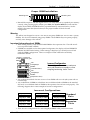
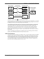
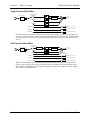
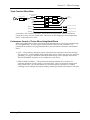
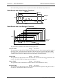
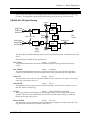
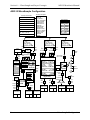
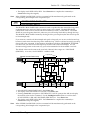
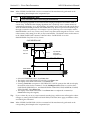
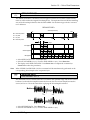
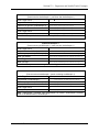
1
Preface
Welcome!
Congratulations and thank you for your purchase of the ENSONIQ ASR-10 Advanced Sampling
Recorder, another milestone in digital sampling keyboards. The ASR-10 revolutionizes the way
sampling is integrated into a workstation, by including 24-bit dynamic effects processing and
allowing the stereo audio input to be monitored, sampled, and resampled through the effects.
And only ENSONIQ offers all the expressive control that turns a sampler into a truly musical
instrument.
Sampling
The ASR-10 features true stereo Sigma-Delta (one-bit) 64 times oversampling technology with a
selectable sample rate of 30kHz or 44.1 kHz. Samples can be recorded from a variety of input
sources including: the stereo audio inputs, the optional DI-10 Digital I/O Board (consumer
AES/EBU digital interface) or the ASR-10’s own Main Audio Output (for resampling). The ASR10 can sample while the sequencer is playing, and can even sample its own sequencer playback.
CD quality output circuitry provides state of the art playback performance. The ASR-10 has all
the on-board editing functions you’ll ever need. Autolooping, volume smoothing, gain
normalization, and multiple types of crossfading provide complete control over your sampled
sounds.
An advanced Time Compression/Expansion function allows you to change the length or tempo
of a sample without affecting the pitch, a necessity for dance music or broadcast needs.
Synthesis Functions
Not only does the ASR-10 provide superb stereo sampling, it is also a full function synthesizer,
allowing you to reshape your sampled sounds with maximum flexibility. 31 voice polyphony,
multiple filters and envelopes, and a comprehensive modulation matrix gives the ASR-10 the
power to manipulate your WaveSamples into many exciting new sounds.
Effects
The ASR-10 incorporates effects processing into a sampler in new and exciting ways — with 50
different 24-bit effect algorithms, the ASR-10 provides a complete arsenal of signal processing
and conditioning tools for your use. State-of-the-art Reverbs, Chorusing, Flanging, Phasing,
Distortion, Digital Delays, and Speaker Effects, will make your sampled sounds and sequenced
music sound totally professional. Signal conditioning effects, like EQ, Compression, and
Ducking can be used to process sounds as they are being sampled to get the perfect sound every
time.
The ASR-10 offers continuous audio monitoring of the stereo audio inputs on two dedicated
Audio Tracks. The audio inputs can be monitored through the effects and if desired, audio input
can be sampled through the effects. Audio Tracks also allow live external signals to play through
the effects processor, so that you can use the ASR-10’s high quality effects on other instruments in
your rig, or allow fellow musicians to plug right in and play — no mixer required! The ASR-10
also has the ability to resample sounds with effects in real time. For example: add reverb to a
drum sample, resample it, then reuse the effects processor to further color your music.
Sequencing
The ASR-10 is also a 16-track sequencing workstation with complete mixdown capabilities. You
can record and edit your performances with a wealth of creative tools. And only ENSONIQ
sequencers allow you to audition your changes to decide which version to keep. This flexible
combination of high fidelity sampling and synthesis, versatile effects processing, and sequencing
is what makes the ASR-10 unique.
i
Preface
ASR-10 Musician’s Manual
Audio Track Recording Capability
Version 2 O.S. adds two tracks of digital audio recording capability to the ASR-10. Audio Tracks
can be recorded directly into RAM (RAMTracks™) or directly to a SCSI storage device (hard
disk, removable media, etc.) via the optional SP-3 SCSI Interface (DiskTracks™). Now you can
combine live performances with MIDI sequenced tracks for full production recording within the
ASR-10. Sing, play your guitar, blow your horn — add whatever live performances you wish.
Recognizing that you want to get up and running quickly, we strongly recommend that you try
the section titled “An Audio Track Tutorial” in Section 18 — Audio Track Applications to get a feel
for the Audio Track recording process.
Support for the Optional DI-10 Digital I/O Interface
ASR-10 Version 2 supports the optional DI-10 Digital I/O Interface. When installed, the DI-10
provides direct digital input and output connection to and from the ASR-10 using RCA-type
connectors. The Digital Output will provide 44.1 kHz digital output of the Main Out mix when
the current effect uses a 44.1 kHz sample rate. The Digital Input can be used for direct digital
sampling from an external digital audio source at 44.1 or 48 kHz.
The Digital Input and Output conforms to the S/PDIF standard (Sony/Phillips Digital Interface
Format). S/PDIF is a digital audio communication standard for digital hardware devices. Be
sure that any digital devices used with the DI-10 conform to this standard. For more information
about using the DI-10 Digital I/O Interface, refer to the DI-10 Manual.
Note:
If you wish to record the 44.1 kHz digital output of the ASR-10 to a DAT recorder, the DAT
recorder must be able to record from its digital input at 44.1 kHz. Some older/consumer DAT
recorders do not record at 44.1 kHz as a copy protection scheme: These DAT recorders will not
record the ASR-10’s 44.1 kHz digital output.
Additional 44.1 kHz Effect Algorithms
The O.S. disk also includes 12 additional effect algorithms, designed exclusively for the ASR-10,
that use the 44 .1 kHz system sample rate (note: polyphony is reduced to 23 voices). Audio
Tracks recorded at the 44.1 kHz sample rate can be output directly from the ASR-10’s Digital I/O
Output jack (which requires the optional DI-10 Digital I/O Interface). For a complete description
of all the effect algorithms, see later in this document.
Clean Up and Maintenance
Only clean the exterior of your ASR-10 with a soft, lint-free, dry (or slightly damp) cloth. You can
use a slightly dampened cloth (with a mild neutral detergent) to remove stubborn dirt, but make
sure that the ASR-10 is thoroughly dry before turning on the power. Never use alcohol, benzene,
volatile cleaners, solvents, abrasives, polish or rubbing compounds.
About The Manual
The Musician’s Manual is your guide to unlocking the full power of the ASR-10. At this point,
you’re probably anxious to plug in your ASR-10 in and get playing. The rest of this section
contains important information about power, grounding, amplification and care of the floppy
drive. We recommend that you read through it, and then follow the Tutorial. The Tutorial is
designed to provide step-by-step procedures for performing basic operations on the ASR-10.
After the initial “I just gotta hear it” phase has passed and you’re ready to utilize the full
potential of the ASR-10, please take the time to read through the sections in this manual on
sampling, programming, sequencing, effects, and storage. The Musician’s Manual is designed to
be used as a reference tool. Both manuals provide valuable information and tips that will speed
up the learning process and ensure your maximum enjoyment of this powerful musical
instrument.
ii
Preface
Thank-you again for choosing ENSONIQ. Enjoy the music!
iii
Preface
ASR-10 Musician’s Manual
Power
1
2
Insert the line cord into the line receptacle on the back of the ASR-10 (2), next to the power switch
(1). Plug the other end of the cable into a grounded AC outlet. The proper voltage for your ASR10 is listed on the Serial Number label on the rear panel. Turn the ASR-10 power on and make
sure the display lights up. If not, check your connections and power source.
Power — Polarization and Grounding
Like many modern electrical devices, your ASR-10 has a three-prong power cord with earth
ground to ensure safe operation. Some products have power cords with only two prongs and no
earth ground. To ensure safe operation, modern products with two-prong power cords have
polarized plugs that can only be inserted into an outlet the proper way. Some products, such as
older guitar amplifiers, do not have polarized plugs and can be connected to an outlet incorrectly.
This may result in dangerous high voltages on the audio connections that could cause you
physical harm or damage any properly grounded equipment to which they are connected, such
as your ENSONIQ product.
To avoid shock hazards or equipment damage, we recommend the following precautions:
• If you own equipment with two pronged power cords, check to see if they are polarized or
non-polarized. You might consider having an Authorized Repair Station change any nonpolarized plugs on your equipment to polarized plugs to avoid future problems.
• Exercise caution when using extension cords or plug adapters. Proper polarization should
always be maintained from the outlet to the plug. The use of polarized extension cords and
adapters is the easiest way to maintain proper polarity.
• Whenever possible, connect all products with grounded power cords to the same outlet
ground. This will ensure a common ground level to prevent equipment damage and
minimize hum in the audio output.
AC outlet testers are available from many electronic supply and hardware stores. These can be
used to check for proper polarity of outlets and cords.
iv
Disk Care
Preface
Ground Loops
Sometimes currents flowing through the ground line generate a signal seen by another part of the
circuit sharing the same ground. In other words, if there are two identical signal paths within a
circuit, they can form a loop which can result in hum and/or noise. If you are using equipment
that has 3-prong “grounded” AC power cords, you may suffer from a ground loop resulting from
the interconnection of this equipment. The following diagram shows how cascading or
“chaining” the output of one 3-prong grounded system into the input of another 3-prong
grounded system with a standard unbalanced 2 conductor cord (like a 1/4” guitar cable) can
result in a ground loop.
Unbalanced Output to Unbalanced Input.
Single conductor shielded cable
SIGNAL PATH
3-Prong
"Grounded"
System
3-Prong
+
+ "Grounded"
System
(circuit ground)
>
<
Unbalanced Output to Unbalanced Input.
Single conductor shielded cable
SIGNAL PATH
3-Prong
"Grounded"
System
2-Prong
+
+"UNGrounded"
System
(circuit ground)
Ground Loop
Earth Ground
FIG. 1
Earth Ground
FIG. 2
Fig. 1 depicts a system interconnection where a ground loop can exist. Fig. 2 depicts a system
interconnection where a ground loop does NOT exist. When interconnecting 3-prong grounded
systems, you can use signal isolation transformers to prevent ground loops. This coupling
transformer effectively isolates two interconnected system signal grounds, while still allowing
the signal to pass through.
AC Line Conditioning
As is the case with any computer device, the ASR-10 is sensitive to sharp peaks and drops in the
AC line voltage. Lightning strikes, power drops or sudden and erratic surges in the AC line
voltage can scramble the internal memory and, in some cases, damage the unit’s hardware. Here
are a few suggestions to help guard against such occurrences:
• A Surge/Spike Suppressor. The cheaper of the options, a surge/spike suppressor absorbs
surges and protects your gear from all but the most severe over-voltage conditions. You can
get multi-outlet power strips with built-in surge/spike suppressors for little more than the
cost of unprotected power strips, so using one is a good investment for all your electronic
equipment.
• A Line Conditioner. This is the best, but by far the more expensive, way to protect your gear.
In addition to protecting against surges and spikes, a line conditioner guards the equipment
against excessively high or low line voltages. If you use the ASR-10 in lots of different
locations with varying or unknown AC line conditions, you might consider investing in a line
conditioner.
Disk Care
v
Preface
ASR-10 Musician’s Manual
Amplification
Connect the Main Audio Outputs of the ASR-10 to the line level inputs of a mixer, instrument
amplifier, stereo, or any other sound system, using 1/4 inch audio cables. If your system is
stereo, connect the Left and Right Main Outputs to two channels of your mixer, stereo, etc. If it’s
mono, use either of the Main Audio Outputs, but make sure nothing is plugged into the other
output. For listening through headphones, plug the phones into the rear panel jack marked
Phones. If you’re running the ASR-10 through a mixer, in stereo, be sure to pan the left input
channel on the mixer fully left, and the right input channel fully right.
It is a good idea to make sure your audio system is turned off (or down) when making
connections, to avoid damaging speakers or other components.
Note:
The ASR-10 outputs are line-level, and are intended to be connected only to line-level inputs,
such as those on a mixer, stereo pre-amp, keyboard amp, etc. Connecting the ASR-10 audio
outputs to a mic-level input, such as a guitar amp or the microphone jacks on a tape deck, is not
recommended, and might result in damage to the device input.
Move the Volume Slider all the way up. As with any digital musical instrument, the ASR-10 will
give the best results if you keep the Volume Slider full on, and use the volume control on your
mixer or amp to adjust its level.
Switch the audio system on, and adjust the amplifier volume for normal listening levels. If you
hear no sound while playing the keyboard, switch the audio system off and check your
connections.
Running Your ASR-10 Through a Home Stereo System
If you are thinking about amplifying your ASR-10 through your home stereo, a word of caution is
in order. A home stereo is great for playing CD’s, albums, tapes — the dynamic range of these
media is limited, and your speakers aren’t usually subjected to extreme volume changes and
frequency transients. While the dynamic range of CD’s is significantly greater than LP’s or tapes,
the output of a CD player is still conservative compared to the uncompressed, unlimited linelevel output of a pro-level keyboard. Running your ASR-10 — or any pro-level keyboard
through a home stereo at high volume levels can damage your speakers, not to mention the
impedance mis-match this can create. If your only means of amplification is your home stereo,
then try to keep your levels on the conservative side.
vi
Disk Care
Preface
Care and Feeding of the Disk Drive
The ASR-10’s built-in disk drive is used to store all your Instruments, Banks, and Sequencer data,
as well as System Exclusive messages from other MIDI devices. The ASR-10 uses a Quad-density
disk drive that can store 1600 Kilobytes of data on a Double-Sided High-Density (DSHD) 3.5”
micro-floppy disk and 800 Kilobytes of data on a Double-Sided Double-Density (DSDD) 3.5”
micro-floppy disk. The disks are enclosed in a protective plastic carrier with an automatic shutter
to protect the diskette from physical damage. It is important not to alter this carrier in any way.
The 3.5” disks have a sliding writeprotection tab so that you can protect
your sounds and sequences against
accidental erasure. Sliding the writeprotection tab in the lower left corner of
the disk so that the window is closed
will allow you to store information on
the disk. Sliding the tab so that the
window is open will protect the disk
against being accidentally reformatted
or having files deleted. Double-Sided
High Density disks can be easily
identified because they have an
additional window (with no writeprotection tab) located on the lower
right corner of the disk.
Double-Sided High-Density (DSHD)
Disk
Window
Write Protect Tab
Double-Sided Double-Density (DSDD)
No Disk
Window
Write Protect Tab
Floppy disks are a magnetic storage medium, and should be treated with the same care you’d
give important audio tapes. Just as you would use high quality audio tapes for your important
recording needs, we recommend using high quality floppy disks for your ASR-10. Here are a few
Do’s and Don’t’s concerning disks and the disk drive.
Do’s:
• Use either Double-Sided High-Density (DSHD) or Double-Sided Double-Density (DSDD) 3.5
inch Micro-floppy disks. Both types are available from almost any computer store and many
music stores carry them as well.
• Keep your disks and the disk drive clean and free of dust, dirt, liquids, etc.
• Label your disks and keep a record of what is saved on each.
• Only transport your unit with nothing in the drive.
Don’t’s:
• Don’t use Single-Sided (SSDD or SSSD) disks. These disks have not passed testing on both
sides. While a single-sided disk might work successfully with the ASR-10, it is possible that
you will eventually lose important data to a disk error if you try using Single-Sided disks.
• Don’t put anything other than a disk or the plastic sheet in the disk drive.
• Don’t transport the unit with a disk in the drive.
• Don’t expose disks to extremes of temperature. Temperatures below 50˚ F and above 140˚ F
can damage the plastic outer shell.
• Don’t expose your disks to moisture.
• Don’t dry your disks in a microwave oven.
• Don’t subject disks to strong magnetic fields. Exposure to magnetic energy can permanently
damage the information on the disk. Keep disks away from speaker cabinets, tape decks,
power cables, airline x-ray equipment, power amplifiers, TV sets, and any other sources of
magnetic energy.
• Don’t eject the disk while the drive is operating (i.e. when the disk drive light is on).
Disk Care
vii
Preface
ASR-10 Musician’s Manual
Backing-up the O.S. Disk
Since floppy disks are vulnerable to the affects of magnetic fields, we highly recommend making
back-up copies of your O.S. disk. Doing so can save time and frustration in the unlikely event
that the O.S. disk becomes damaged. Since the tutorial files and the additional 44.1 kHz effect
algorithms are on the O.S. disk, you will need a HD (high density) disk to save all of the
information. We’ll use the COPY FLOPPY DISK command to back up the disk. Here’s how:
1. Slide open the plastic write-protect tab on the original O.S. disk (you should be able to see
through the little square hole) so that the disk is write-protected (protected from being written
to). This is an extra precaution to safeguard the data.
2. Press Command, then System•MIDI, and scroll to the COPY FLOPPY DISK command.
3. Press Enter•Yes.
The display shows INSERT SOURCE DISK (the one you want to copy).
4. Insert the source disk, then press Enter•Yes.
The drive will engage and the display will flash READING SOURCE DISK. Once the drive
stops, the display will change to show INSERT DEST DISK.
5. Insert the destination disk (the one you want to copy to) and press Enter•Yes.
If the destination disk is unformatted, the display will ask ERASE AND FORMAT DISK?
Press Enter•Yes to format the disk. When formatting is complete, the drive will engage and
the display will flash WRITING DEST DISK.
After writing to the destination disk, the display will read VERIFYING DEST DISK. If the
copy is complete, the display will read DISK COMMAND COMPLETED.
If you do not want to copy all of the tutorial files or the 44.1 kHz effect algorithms, use the
Command/System•MIDI, COPY O.S. TO DISK command (as described in Section 2 —
System•MIDI).
We recommend that you use the copied O.S. disk for daily use, and store the original O.S. disk in
a safe place. If your O.S. disk becomes damaged and you do not have a back-up copy made, your
local Authorized ENSONIQ Dealer can make a new copy for you (you must supply the disk).
viii
Backing-Up the O.S. Disk
Preface
Accessories
These optional accessories are available from your Authorized ENSONIQ Dealer:
• OEX-6sr Output Expander — The OEX-6sr gives the ASR-10 six additional outputs, grouped
in three stereo pairs in addition to the built-in stereo outputs. Each WaveSample, or an entire
instrument/track can be assigned to any of the stereo pairs and panned within the stereo field.
• SP-3 SCSI Kit — This SCSI (Small Computer Serial Interface) allows the ASR-10 to
communicate with a hard drive, CD ROM player, or computer. Hard drives provide a faster,
more convenient way to store instrument, sequencer, bank, and MIDI files. The SP-3 must be
installed by an Authorized ENSONIQ Repair Station.
• DI-10 Digital I/O Board (S/PDIF) — Allowing digital input and output using RCA-type
connectors. The DI-10 must be installed by an Authorized ENSONIQ Repair Station.
• Model CVP-1 CV PEDAL — A Control Voltage Foot Pedal which can be assigned as a
modulator within the voice section of the ASR-10 or used as a volume pedal.
• ENSONIQ Model SW-10 Dual Foot Switch — Can be used for hands-free patch select control
(when plugged into the Patch Select jack) or used for modulation control, voice sustain, or
starting, stopping, and continuing the internal sequencer (when plugged into the Foot Switch
jack).
• ENSONIQ Model SW-6 Foot Switch — A single damper piano style foot switch, for sustain,
or to function as the right patch select button.
• CDR Series — These CD ROMs offer a vast array of instruments, banks, and sequence/song
arranged in directories by file types. The CDR Series also features Direct Macros, which
allows instant access (direct-dial) to any instrument file.
• AS –Series Sound Libraries — The AS sound libraries are designed exclusively for the ASR10, provided on five High Density disks.
• SL, SLT, and ESS Sound Libraries — The ASR-10 can read all of the disks designed for the
EPS Series. These disks offer the largest, most accurate, responsive, and musical sampled
sounds available anywhere. These sounds are divided into three separate libraries: SL, a
series of five-disk sets featuring sounds specifically designed for the EPS-16 PLUS, but fully
compatible with the ASR-10; SLT, a series of ten-disk packs originally designed by top sound
programmers for the EPS, also compatible with the ASR-10; and ESS, three-disk “Signature
Series” sets designed by renowned industry performers and producers like Joey DeFrancesco,
Jason Miles, Maurice White, The System, Nile Rodgers, David Hentschel, and others.
An Important Note About Non-ENSONIQ Accessories and Your ENSONIQ
Warranty
ENSONIQ highly recommends that users who wish to add SCSI or a Digital I/O Interface to their
ASR-10 use ENSONIQ-made accessories. However, for those who wish to purchase a nonENSONIQ product, there are some important things to know about non-ENSONIQ products and
your ASR-10’s warranty:
• ENSONIQ will not approve any Non-ENSONIQ SCSI kits or Digital I/O Interfaces for the
ASR-10.
• If your ASR-10 requires servicing, and a non-ENSONIQ accessory is installed, ASR-10 owners
will pay a service fee to have it removed so that a technician can diagnose the base unit.
• If it is determined that the use of an unapproved Non-ENSONIQ product caused damage,
then the repair of that damage is not covered by the ENSONIQ warranty. Any nonENSONIQ product which requires opening the case must be installed by an Authorized
ENSONIQ Repair Station.
• In addition, if it is found that continued use of a non-ENSONIQ product causes damage to
your ASR-10, any future service that your unit might require may not be covered under the
ENSONIQ warranty.
An Important Note
ix
Preface
ASR-10 Musician’s Manual
Need More Help?
Whether you’re an aspiring programmer looking for additional information about basic sampling
techniques and MIDI theory, or a professional sound designer working with advanced
applications, you may want more detailed information that is beyond the scope of this manual.
The following books can help enhance your understanding of sampling, synthesis, MIDI, and
related topics. These, in addition to the numerous monthly magazines, provide a wealth of
information. While we don’t endorse any one of these publications, we offer this partial list as a
resource for you to draw on.
The Mix Bookshelf
For prices and more information call: 1-800-233-9604
MIDI
MIDI FOR MUSICIANS, Craig Anderton
THE MIDI MANUAL, David Huber
THE MIDI HOME STUDIO, Howard Massey
THE NEXT MIDI BOOK, Rychner & Walker
THE MIDI BOOK, Steve De Furia, Joe Scacciaferro
THE MIDI RESOURCE BOOK, Steve De Furia, Joe Scacciaferro
HOW MIDI WORKS, Dan Walker
MIDI SYSTEMS & CONTROL, Francis Rumsey
USING MIDI, Helen Casabona, David Frederick
MIDI, THE INS, OUTS AND THRUS, Jeff Rona
SAMPLING
THE SAMPLING BOOK, Steve De Furia, Joe Scacciaferro
SAMPLING BASICS, Bobby Maestas
SYNTHESIZERS
GUITAR SYNTH & MIDI, Guitar Player Magazine
SECRETS OF ANALOG AND DIGITAL SYNTHESIS, Steve De Furia
SYNTHESIZER PERFORMANCE & REAL TIME TECHNIQUES, Jeff Pressing
SYNTHESIZER BASICS, Dean Friedman
MUSIC & TECHNOLOGY, H.P. Newquist
A SYNTHESIST'S GUIDE TO ACOUSTIC INSTRUMENTS, Howard Massey
Alfred Publishing Company
For prices and more information call 1-818-891-5999
MIDI
ADVANCED MIDI APPLICATIONS, GPI
BASIC MIDI APPLICATIONS, GPI
WHAT IS MIDI?, GPI
SYNTHESIZERS
BEGINNING SYNTHESIZER, GPI
PLAYING SYNTHESIZERS, GPI
SYNTHESIZER PROGRAMMING, GPI
Hal Leonard Publishing
For prices and more information call 1-414-774-3630
MIND OVER MIDI, GPI
SYNTHESIZER TECHNIQUE (REVISED), GPI
x
Preface
Monthly Magazines
The following magazines offer many specific articles and columns that can provide a plethora of
useful information.
THE TRANSONIQ HACKER
For prices and more information about this independent news magazine for ENSONIQ
Users, call 1-503-227-6848
KEYBOARD
For subscription rates and more information call 1-800-289-9919
ELECTRONIC MUSICIAN
For subscription rates and more information call 1-800-888-5139
HOME & STUDIO RECORDING
For subscription rates and more information call 1-818-407-0744
MIX
For subscription rates and more information call 1-800-888-5139
EQ
For subscription rates and more information call 1-212-213-3444
xi
Section 1 — Controls & Architecture
This section provides an introduction to the ASR-10’s many controls and rear panel connections,
a conceptual overview of the system, a guide to understanding memory, and a discussion of
editing various types of parameters. We suggest you read this section carefully — it will help
you get the most out of your ASR-10.
Rear Panel Connections
MIDI
1
2
Thru
In
Out
3
4
5
Patch Select
6
Foot Switch
7
Pedal•CV
8
1) Power
The power switch turns the ASR-10 on and off. When you turn the power on, the display lights
up and shows “PLEASE INSERT DISK,” which is the prompt to load the operating system.
2) AC Line In
The supplied line cord connects here. The correct voltage for the ASR-10 is on the rear panel
along with the serial number. If you travel, remember the ASR-10 will only operate on the listed
voltage.
3) MIDI Thru
This jack “passes on” all MIDI (Musical Instrument Digital Interface) information received by the
ASR-10 to other MIDI devices. Information generated by the ASR-10 itself does not go to this jack
— the Thru jack merely echoes what comes into the MIDI In jack.
4) MIDI In
This jack receives MIDI information from other MIDI instruments or computers.
5) MIDI Out
This jack transmits MIDI information generated by the ASR-10 keyboard and/or sequencer to
other instruments and computers.
6) Patch Select (Foot Switch)
If you connect the optional SW-10 Dual Foot Switch in this jack, it duplicates the function of the
Patch Select buttons, allowing hands-free patch select changes. This jack requires a dual foot
switch and will not work properly with a single foot switch (SW-2 or SW-6).
7) Foot Switch
This jack supports either one or two foot switches depending on what is plugged into it:
• If you plug the ENSONIQ Model SW-2 Foot Switch (which came with your ASR-10) into this
jack, it will act as a Sustain pedal. Holding it down will cause notes to continue to sustain
after the key has been released.
• Or you can connect the optional ENSONIQ Model SW-10 Dual Foot Switch here. The SW-10 is
a dual (piano-type) foot switch with two separate pedals. When the SW-10 is connected, the
Right Foot Switch will act as a sustain pedal and the Left Foot Switch is assignable.
1
Section 1 — Controls and Architecture
Note:
ASR-10 Musician’s Manual
If you are using a single foot switch (SW-2 or SW-6), the Edit/System•MIDI, LEFT FOOT SW
parameter should be set to OFF. This will prevent unexpected behaviour. Remember that the
Foot Switch jack is optimized for use with a dual foot switch (SW-10), and when a single foot
switch is connected, it behaves like the Right Foot Switch.
When the SW-2 is connected
to the Foot Switch jack:
It acts as the
Sustain Pedal.
When the SW-10 is connected to
the Foot Switch jack:
The Left Foot Switch
is assignable.
The Right Foot Switch acts
as the Sustain Pedal.
A parameter on the Edit/System•MIDI page (press Edit, then System•MIDI, then scroll until
the display reads “LEFT FOOT SW=OFF”) determines the function of the Left Foot Switch.
Tip:
2
The Sustain pedal can be used to dynamically “latch” the current amount of pressure being
exerted on the keyboard. Here’s how:
1) Select a sound that responds to pressure. Choose a sustaining sound like an organ.
2) Play a key and press into the keyboard until you can hear the pressure modulation
affect the sound of the note.
3) Press and hold the Sustain pedal.
4) Release the key. You will hear that the sound continues to be modulated by pressure
at the depth to which you were pressing.
5) Play a different key. Notice that the new note is not modulated. You can now press
into the keyboard and modulate the new note independent of the note that is
sustained. When the current pressure output exceeds the latched level, pressure on
the new note will modulate both notes.
6) To release the “latched” pressure value on the sustained note, either press the
“latched” key again, or release the Sustain pedal.
Rear Panel Connections
Section 1 — Controls and Architecture
8) Pedal•CV
This jack is for connecting an optional ENSONIQ Model CVP-1 Control Voltage Foot Pedal,
which is assignable as a modulator to various parameters within the ASR-10. The pedal gives
you a handy alternative modulation source when, for example, you would want to use the Mod
Wheel but both hands are busy.
ENSONIQ
CVP-1
Control Voltage Foot Pedal
A CV pedal plugged into this jack can also act as a Volume pedal, controlling the volume of the
currently selected Instrument•Sequence Track(s). A parameter on the Edit/System•MIDI page
(press Edit, then System•MIDI, then scroll until the display reads PEDAL=VOLUME MIDI=7),
determines whether the CV pedal will act as a modulator or as a volume pedal. Set to
PEDAL=VOLUME to use the CV pedal to control volume.
Pedal/CV Specs: 3-conductor (Tip= control voltage input, Ring=510 ohm resistor to +5 Volts,
Sleeve= ground). 36 KOhm input impedance, DC coupled. Input voltage range=0 to 3 volts DC.
Scan rate=32mS (maximum recommended modulation input= 15 Hz). For use with an external
control voltage, use a 2-conductor cable with the voltage on the tip and the sleeve grounded.
Rear Panel Connections
3
Section 1 — Controls and Architecture
ASR-10 Musician’s Manual
Rear Panel Connections Cont’d.
Digital I/O
SCSI
Output
Expander
10
11
Mic
Line
Input
Level
Out
In
9
12
13
Audio Input
B/Right A/Left
Main Out
Right/Mono
Left/Mono
15
14
Phones
16
9) Digital I/O — Input/Output
The DI-10 Digital I/O Interface (S/PDIF) provides direct Digital Input and Output connection to
and from the ASR-10 using RCA-type connectors. The Digital Output will provide direct 44.1
kHz digital audio output of the Main Output mix when the current effect uses a 44.1 kHz sample
rate. The Digital Input can be used for direct digital sampling from an external digital audio
source at 44.1 or 48 kHz.
The Digital Input and Output conforms to the S/PDIF standard.
Note:
If you wish to record the 44.1 kHz digital output of the ASR-10 to a DAT recorder, the DAT
recorder must be able to record from its digital input at 44.1 kHz. Some older/consumer DAT
recorders do not record at 44.1 kHz as a copy protection scheme: these DAT recorders will not
record the ASR-10’s 44.1 kHz digital output.
10) SCSI Interface
This space is for the optional SP-3 SCSI kit that allows the ASR-10 to transfer data to and from a
SCSI-compatible hard disk, CD ROM player, or exchange information with computers at very
high speed.
11) Output Expander (AUX 1, 2, 3)
This multi-pin connector is used to connect the optional OEX-6sr Output Expander box, which
provides the ASR-10 with three pairs of stereo outputs (or 6 individual outs) in addition to the
built-in stereo outputs. Each WaveSample, or an entire Instrument•Sequence Track, can be
assigned to any of the three AUX stereo pairs and can be independently panned within the stereo
field.
12) Mic/Line Switch
This switch is used to change between either a mic (up) or a line (down) level input source.
13) Input Level Trim Control
This knob allows you to amplify the level of the external signal source.
4
Rear Panel Connections
Section 1 — Controls and Architecture
14) Audio Input — B/Right and A/Left
These jacks are the Right and Left Audio Inputs into the ASR-10 for sampling or Audio Track
monitoring of external analog audio sources.
SPECS: 140 KOhm input impedance, AC coupled. The Audio Inputs have 2 ranges: Line and
Mic. With the Mic/Line switch set to Line, the
ASR-10 will accommodate signals from +15.5dBV (Input Level Trim control fully
counterclockwise) to -16.5dBV (Input Level Trim control fully clockwise). With the Mic/Line
switch set to Mic, the ASR-10 will accommodate signals from -11.5dBV (Input Level Trim control
fully counterclockwise) to -43.5dBV (Input Level Trim control fully clockwise). Matching the
appropriate input level with the correct settings of the Mic/Line switch and Input Level Trim
control will bring the external signal source up to clipping level.
15) Main Out — Right/Mono and Left/Mono
To operate the ASR-10 in stereo, connect these outputs to two discrete channels of your mixer
and pan the mixer channels right and left. Note that either of the audio outputs can be used as a
mono output. If you want to listen to the output in mono, make sure that only one of the output
jacks is connected.
16) Phones
To listen to the ASR-10 in stereo through headphones, plug the phones into this jack. The phones
output contains a mix of the signal from the main outputs. Headphone volume is controlled by
the volume slider on the front panel. Note that plugging headphones into this jack does not
automatically turn off the audio in the right and left outputs.
Rear Panel Connections
5
Section 1 — Controls and Architecture
ASR-10 Musician’s Manual
Front Panel Controls
Almost everything you do on the ASR-10 — whether it’s selecting a sound, editing that sound,
adjusting the tuning, etc. — is controlled from the front panel using the following controls:
Instrument
Env 1
Env 2
Env 3
Load
1
(Select Preset)
Seq•Song
Pitch
2
3
Filters
Amp
Command
4
System•MIDI
LFO
(Directory)
7
5
Wave
6
Layer
(Create Preset)
Edit
Effects
8
9
Track
Cancel
0
Volume
Data Entry
No
1
2
Enter
3
Yes
4
1) Volume Slider
This controls the overall volume of the ASR-10 audio outputs.
2) Mode Buttons
These three buttons are the key to finding your way around the ASR-10. The ASR-10 is always in
one of these three Modes — LOAD, COMMAND, or EDIT. The current mode is selected by
pressing the appropriate mode button. The highlighted word in the upper left corner of the
display tells you which is the current mode.
• LOAD mode is the one you will be in most often — since the ASR-10 lets you continue playing
while loading sounds and sequences, LOAD mode also doubles as the “Performance” mode.
When the LOAD indicator is flashing, the display is showing you disk files for loading. When
the LOAD indicator is lit but not flashing, the display is showing you the name(s) of the
instruments in the Internal Memory.
Tip:
In flashing LOAD mode (when the LOAD indicator is flashing), successive presses of the
Instrument, Seq•Song, System•MIDI, or Effects buttons will scroll through the available files
of that type on the selected storage device.
• COMMAND mode is used to execute a wide variety of commands, such as: saving
instruments, banks, and sequences to disk; copying instruments, layers, and WaveSamples
from one internal location to another; creating and modifying sequences and songs; and
manipulating WaveSamples and their loops in various ways... just to name a few.
Tip:
In COMMAND mode, successive presses of each of the 14 page buttons will scroll through the
Command screens, one at a time.
• EDIT mode is used to select and modify a great many variables — or parameters — ranging
from the volume of a WaveSample, to the velocity response of the instrument, to the MIDI In
Mode. Edit mode is also the mode in which all sequence recording and mixing is done.
Tip:
6
In EDIT mode, successive presses of each of the 14 page buttons will scroll through the Edit
screens, one at a time.
Front Panel Controls
Section 1 — Controls and Architecture
3) Page Buttons
Within each mode, the available disk files, commands, and parameters are organized into Pages.
A page is selected by pressing one of these fourteen page buttons. Once you are on the correct
page, you use the Data Entry Controls to scroll through the files, commands or parameters on
the page. A given page will have different functions depending on the current mode. Each mode
has a different set of pages available. Not all fourteen page buttons are active in all three modes.
The ten numbered page buttons also double as a numeric keypad for “direct-dialing” a given disk
file, command, or parameter or for sending MIDI Program Changes.
4) Data Entry Controls
Once you are in the desired mode and have selected the proper page, you use the controls in the
data entry section to: locate and load the desired file (in Load mode); locate and execute the
desired command (in Command mode); or locate and modify the value of the desired parameter
(in Edit mode).
• The Data Entry Slider and the Up and Down Arrow buttons will: move through the files on
the current disk or directory (in flashing LOAD mode); change the value of the current
parameter (in Edit mode); or respond when the ASR-10 asks you for further input during the
execution of a command (in Command mode).
• The Left and Right Arrow buttons are used primarily to move to the next parameter or
command on the current page.
Tip:
To advance by screens (instead of by parameters), while holding down the Right Arrow button,
press the Up Arrow button, or while holding down the Left Arrow button, press the Down
Arrow button.
• The Enter•Yes and Cancel•No buttons are used to either proceed with or cancel the function
currently showing on the display.
Tip:
When editing any parameter, pressing Cancel•No will reset the parameter to the value it was set
to before it was last edited.
Tip:
In Load mode, successive presses of the Cancel•No button will alternate between solid and
flashing Load modes.
Tip:
When editing any parameter that has a center value, there is an easy way to reach that value.
While holding down the Down Arrow button, press the Up Arrow button, then quickly release
both buttons.
Parametric Programming
The method used to modify or edit programs, presets and system parameters is called Pagedriven Parametric Programming, which sounds like a mouthful, but don’t worry. Once you’ve
grasped a few basic concepts you’ll find that operating the ASR-10 is quite simple, given its many
capabilities.
It is likely that you have already encountered some form of parametric programming on other
synthesizers or samplers. What this means is that instead of having a separate knob or slider for
each function, you have one master Data Entry Slider and the Up/Down and Left/Right Arrow
buttons, which adjust the value of whichever parameter you select.
This approach has many advantages, the most obvious is that it greatly reduces the amount of
hardware — knobs, switches, faders, etc. needed to control a wide variety of functions. If the
ASR-10 had a separate control for each function, it would literally have hundreds of knobs.
Front Panel Controls
7
Section 1 — Controls and Architecture
ASR-10 Musician’s Manual
Additional Front Panel Controls
6
Left
7
Right
8
Sample
FX Select
Source Select
FX Bypass
Peak
5
Signal
Input Level
Record
1
2
3
4
5
6
7
8
Instruments
Sequence Tracks
Stop
A
B
Audio Tracks
Continue
10
11
9
Play
5) Display
The ASR-10 Display is divided into two main sections: the Indicator Lights in the top half of the
window and the 22-character Alphanumeric Display at the bottom of the window.
Mode Indicator
LOAD
Page Indicator
INST
FILE 2
Sequencer
Status
STOP
GRAND
PIANO
22-character Alphanumeric Display
The indicator lights will tell you which mode the ASR-10 is in (Load, Command, or Edit); which
page it is on; and the sequencer status (Stop, Play, Record, etc.). The 22-character alphanumeric
display is used to show you information about specific files, commands, parameters, etc. It will
also ask you for additional input when necessary, such as which track you want to load an
instrument into, or which WaveSample you want to edit.
6) Input Level LED Meters
These 2 dedicated Input Level meters provide separate Left/Right metering of the Audio Input
levels, pre-FX, at all times. The green Signal LEDs light at -24 dB. The red Peak LEDs light at 6
dB below clipping.
7) Sample•Source Select Button
This button is used to initiate sampling (digitally recording sounds) by the ASR-10. The Record
Source selected on this page will determine the audio signal that will be monitored on the Audio
Tracks.
8
Front Panel Controls
Section 1 — Controls and Architecture
8) FX Select•FX Bypass Button
This button acts as the “master” control switch for the built-in effects, determining which, if any
effect will be used and how it will interact with the instruments that reside in the internal
memory. The controls on this page also determine the current sample rate and polyphony.
9) Instrument•Sequence Track Buttons — 1 through 8
These eight buttons are used to select, deselect, and “stack” the various instruments that are
loaded into the internal memory of the ASR-10. For each of the eight locations, the two LEDs
above the button indicate whether an instrument is Loaded into that location (red LED lit) and
whether it is Selected (yellow LED lit). See “Playing Instruments” later in this section for a full
discussion of the Instrument•Sequence Track buttons.
Each instrument location is also a sequencer track — that is, whatever is recorded on track 1 of a
sequence will play the instrument that is loaded into location #1. When you are recording,
editing or mixing sequences and songs, you use these buttons to select the current track.
10) Audio Track Buttons — A and B
Audio Tracks are used to record RAMTracks and DiskTracks. The two Audio Track buttons
control audio monitoring of the stereo audio inputs through effects (if desired), enabling you to
monitor during sampling, sing along (or play a guitar) to sequencer playback, or record your
performance to the Audio Tracks. Each Audio Track has its own Edit/Track MIX, PAN, and
OUT bus assignment. The signal monitored on Audio Tracks is the signal that will be sampled or
recorded to the Audio Tracks.
Each Audio Track button contains 2 LEDs:
• The left LED is red, and is labelled “Source Monitor.” When lit, it indicates that the Audio
Track Record Source (set on the Sample•Source Select page, REC SRC parameter) can be
monitored on the Audio Track, and that a voice is being used to monitor this audio signal.
When the Source Monitor LED is off, the Audio Track is muted and inaudible.
When REC SRC= MAIN-OUT, the audio inputs are disabled, and both Source Monitor LEDs
remain off at all times. This happens because REC SRC= MAIN-OUT recording is all ASR-10
generated audio that is routed to BUS1, 2, or 3, and the Source Monitor voices are not needed
to monitor this REC SRC, as it is always audible out the Main Outs.
• The right LED is yellow, and is labelled “SELECTED.” When lit, it indicates that the track is
selected for parameter editing and/or Audio Track Recording, and that the Audio Signal
Source being monitored on the track is selected for sampling. When the SELECTED LED is
off, the track’s Edit/(audio) Track parameters cannot be edited, and the Audio Signal Source
being monitored on the track will not be sampled and will not be recorded to Audio Tracks.
See Section 12 — Sequencer and Audio Track Concepts for more information on Audio Tracks.
11) Sequencer “Transport Controls”
These three buttons are used to control the ASR-10’s internal multi-track sequencer.
Front Panel Controls
9
Section 1 — Controls and Architecture
ASR-10 Musician’s Manual
Performance Controllers
The ASR-10 features a number of real-time performance controllers that can modify sounds as you
play for maximum expressiveness. Three of the most important controllers are located to the left
of the keyboard:
Patch Select
Buttons
Pitch Bend
Wheel
Modulation
Wheel
• PATCH SELECT BUTTONS — These two buttons are used to select alternate groups of voices
(called Layers) within a sound. The ASR-10 can be programmed so that the sound changes
(sometimes in subtle ways, sometimes radically) when you play notes with one or both Patch
Select buttons held down As you play instruments on the ASR-10, make sure you explore
what these buttons do to each sound.
• PITCH BEND WHEEL — This wheel bends the pitch of a note up or down. The wheel is
normally centered, where it has no effect on the pitch — moving the wheel up or down will
bend the note by the amount specified in the Bend Range parameters contained on the
Edit/System•MIDI page (for GLOBAL BEND RANGE) and on the Edit/Pitch page (for an
individual WaveSample’s BEND RANGE).
• MODULATION WHEEL — Perhaps the most common use of the Mod Wheel is to add
vibrato, but it can also be assigned as a modulator anywhere within the ASR-10 voice
architecture to alter the pitch, brightness, volume and a great many other aspects of the sound.
10
Performance Controllers
Section 1 — Controls and Architecture
Pressure (After-touch)
Another important controller is Pressure. Pressure (often called after-touch) is a modulator that
allows you to change the sound in various ways by pressing down harder on a key or keys after
the initial keystrike. The ASR-10 keyboard is capable of generating two types of pressure —
Channel Pressure and Poly-Key™ Pressure.
Like the mod wheel or foot pedal, pressure is a modulator and can be chosen wherever a
modulator is selected in the programming section (see Section 9 — WaveSample and Layer Concepts)
of the ASR-10. Pressure can be assigned to alter the pitch or volume of voices, filter cutoff
frequency, LFO rate or depth, pan location, etc.
There are two types of Pressure:
• Channel Pressure, also called Mono pressure, affects all notes that are playing when you exert
pressure on any of the keys. For example, if you play a three note chord, pressing down
harder on any of the three notes of the chord will modulate all three notes. This type of
pressure is the more common of the two types.
Most MIDI instruments that currently implement pressure send and receive only channel
pressure. If you are playing such an instrument from the ASR-10, you should set the ASR-10
to send channel pressure. (Note that some devices, including all ENSONIQ products, respond
to both types of pressure.)
• Poly-Key™ Pressure, also referred to as polyphonic pressure, is a more sophisticated and
expressive type of pressure. Poly-Key pressure affects each key independently. For example,
if you play a three-note chord, pressing down harder on any of the three notes of the chord
will modulate only that note. The other two notes will remain unaffected.
Each Instrument•Sequence Track can be programmed to generate Poly-Key pressure,
channel pressure or none at all. If you wish to change the pressure type for a given track, you
can do so on the Edit/Instrument page.
Tip:
Poly-Key pressure generates a tremendous amount of data and will consume sequencer memory
much faster than other types of events, such as notes and program changes. You should turn
pressure off when sequencing instruments which do not respond to pressure, such as piano and
drum sounds.
About Pressure
11
Section 1 — Controls and Architecture
ASR-10 Musician’s Manual
Architecture
“Booting” the ASR-10
Insert the power cord into the line receptacle on the back of the ASR-10, next to the power switch.
Plug the other end of the cable into a grounded AC outlet. The proper voltage for your ASR-10 is
listed on the Serial Number label on the rear panel. Turn the ASR-10 power on and make sure
the display lights up. If not, check your connections and power source.
The ASR-10 Operating System (O.S.) — the computer program that tells the hardware what to do
— is “disk based.” This means that each time you turn the ASR-10 on, the first disk you insert
must be one containing an ASR-10 Operating System (see the disk label). This is called “booting”
the machine. Insert the disk with the label facing up and the sliding metal door facing away from
you. The display will read LOADING SYSTEM while the O.S. is being loaded. You should
always use the latest (highest-numbered) Operating System. If the first disk you put in the drive
doesn’t contain the ASR-10 Operating System — the display will flash O.S. NOT ON DISK or
DISK NOT FORMATTED. Just remove that disk and insert a proper ASR-10 O.S. disk.
Note:
We recommend that you use a copy of the original O.S. Disk for daily use, and store the original
O.S. Disk in a safe place. For more information, see the Preface.
Right after the ASR-10 is finished loading the Operating System, and before it puts itself into
LOAD mode, it will calibrate its keyboard. During calibration the software scans each key and
optimizes its velocity and pressure response. The display will briefly read TUNING KBD HANDS OFF. It is important that you don’t play or hold down any keys during this time (see
below).
Once it has “booted” the ASR-10 is ready to operate, but it won’t make any sound until you
LOAD an instrument into its internal memory and then select that instrument by pressing its
Instrument•Sequence Track button. These functions will be covered later in this section.
Keyboard Calibration
Each time you switch it on, the ASR-10 will go through a boot-up routine that includes
calibrating the keyboard — a process by which the ASR-10 software is able to scan the entire
keyboard and optimize the response of each key. This ensures that the keyboard is always fine
tuned for the best possible response. The calibration process only takes about three seconds.
Never play the keyboard while it’s calibrating:
After you turn on the ASR-10 and insert the Operating System in the drive, the display will show
LOADING SYSTEM, then TUNING KBD - HANDS OFF. You should not play the keyboard
while this message is on the display. After about three seconds, the display will automatically
switch to show the instrument files on the current disk and the ASR-10 is ready for use.
If you do play the keyboard while it’s calibrating:
Playing keys during calibration will cause the display to show KBD FAILED - RETRY? Press
Enter•Yes to allow it to calibrate again, taking care not to play keys this time. In short, you
should make it a point not to play keys during the first few moments after turning the unit on.
If the KBD FAILED message appears without touching the keys:
If the display repeatedly shows KBD FAILED RETRY? even when you are not touching keys
during calibration, this would indicate a hardware problem and the unit should be serviced by an
Authorized ENSONIQ Repair Station.
Using the ASR-10 as a sound module only, after getting repeated KBD FAILED messages:
If you want to use the unit as a sound module after the display shows repeated KBD FAILED
RETRY? messages, press Cancel•No. This will disable the Poly-Key™ keyboard completely, but
the ASR-10 will respond normally to all button presses and incoming MIDI information from
another MIDI instrument.
12
Architecture
Section 1 — Controls and Architecture
Memory
Disk Memory vs. Internal Memory
The instruments, banks, and sequences that the ASR-10 plays are stored on 3.5” micro-floppy
disks. The ASR-10 uses a high-density (HD) drive, allowing you to uses both Double-Sided
High-Density and Double-Sided Double-Density disks:
Disk Type
Format
(Sector Offset)
Kilobytes
Sample Words
Blocks
High-Density
ENSONIQ
(offset 0)
1600
800k
3176
High-Density
COMPUTER
(offset 1)
1440
720k
2863
Double-Density
ENSONIQ
(offset 0)
800
400
1585
Double-Density
COMPUTER
(offset 1)
720
360k
1426
A Block is a handy unit that the ASR-10 uses to measure Internal and Disk memory — 1
Block=256 sample words; 4 Blocks=1k sample words.
Sounds and sequences must be loaded from the disk into the internal memory of the ASR-10
before they can be played. Once it’s loaded into memory, an ASR-10 sound or sequence is
completely independent of the copy on the disk — you can do anything you want to it without
harming the version on the disk, unless you intentionally save the changes. You should feel free
to experiment as much as you like with the instrument, layer, and WaveSample parameters of
any sound that came with the ASR-10. As long as you have it safely on the disk, you can just
reload it and start over if your experiments go awry.
Important:
The data in the ASR-10 internal RAM Memory is not retained when the power is turned off.
Anything in memory, whether Instruments, Banks, or sequencer data, must be saved to disk
before you switch the power off, or it will be gone forever.
Warning!
If you are unfamiliar with installing SIMMs, or do not want to risk the possibility of causing
damage to the SIMMs or your ASR-10, we highly recommend having an Authorized ENSONIQ
Dealer install them. We also recommend reading all of the SIMM information before attempting
to install SIMMs in your ASR-10.
Purchasing SIMMs
Here is some important information you should know about purchasing the proper SIMMs:
• The ASR-10 was designed to use 1m x 8 or 4m x 8 (Macintosh) non-parity SIMMs (not 1m x 9
or 4m x 9 parity SIMMs). We highly recommend using this type of SIMMs.
• We do not recommend using parity SIMMs (designed for IBM PC compatibles). These SIMMs
may not operate properly, and may cause damage to the ASR-10.
• We recommend using SIMMs with an access speed of 80 nanoseconds or faster.
About Memory
13
Section 1 — Controls and Architecture
ASR-10 Musician’s Manual
What is a SIMM?
SIMM is an acronym which stands for Single In-line Memory Module. SIMMs have become the
industry standard used by most computers (both IBM and Mac compatible) to expand the
computer’s memory. Because of this, SIMMs are readily available in most computer software
stores, and from mail order organizations. The ASR-10 memory, like a computer, is also
expanded using SIMMs.
Drams (amount varies)
Alignment
Notch
Latching Hole
Edge Connector
Internal Memory
As it comes out of the box, the ASR-10 contains 2 MegaBytes or 1 MegaWord of internal memory
(a word is one single sample, or 16 bits). That’s enough for 31.5 (mono) or 15.75 (stereo) seconds
of sampling at a 29.8 KHz sample rate, or about 400,000 notes of sequencer memory.
This internal memory is shared by sounds and the sequencer. The memory is distributed
dynamically between instruments and sequences, which means that the more sounds you have in
memory, the less sequencer memory you have, and vice versa.
Expanding the ASR-10 Memory
If you want to expand the memory, the ASR-10 can address up to 16 MegaBytes/8 MegaWords,
using industry standard 1m x 8 or 4m x 8 non-parity SIMMs. There are five different memory
allocations, as shown below:
SIMMS 1m x 8 (standard)
4m x 8
1m x 8
1m x 8 & 4m x 8
SIMMS Used
two
two
four
two & two
MegaBytes
2
8
4
10
MegaWords
1
4
2
5
Blocks
3,800*
16,000*
7,900*
20,000*
* Actual block count may vary due to different O.S. Versions.
4m x 8
four
16
8
31,000*
Accessing SIMMs
To access the SIMMs in your ASR-10, make sure all cables, especially the power cable, are
unplugged from the ASR-10. Turn the unit upside down on a soft surface with the keys facing
away from you. Remove the two screws holding the trap door and remove the trap door from
the bottom of the ASR-10. As it comes from the factory, the ASR-10 would look like this
underneath the trap door:
STD
EXP
Move jumper when
adding expansion memory
MEM EXP JMP
Standard SIMM Slots
Jumper is connected for
STANDARD SIMM Memory.
Move to the other pins when
using Expansion SIMM Slots.
Two 1-MegaByte SIMMs
Expansion SIMM Slots
Expansion slots are empty
14
About Memory
Section 1 — Controls and Architecture
You will notice that there are two slots with SIMMs installed, and two slots that are empty.
These empty slots are called Expansion SIMM Slots, and are used for adding additional SIMMs
(when expanding the memory). Directly above the Standard SIMM Slots, you will find the
Memory Expansion Jumper.
About the Memory Expansion Jumper
The Memory Expansion Jumper allows you to access the information in the Expansion SIMM
Slots. It must be moved to the EXP (Expansion) pins in order for any SIMMs plugged into the
expansion slots to be recognized. If you do not have any SIMMs plugged into the Expansion
slots, the Memory Expansion Jumper must be installed on the STD (Standard) pins, or the ASR-10
will not boot up (display will be blank).
Installing SIMMs
Memory is user-installable in 1, 2, 4, 5, and 8 MegaWord configurations, with 1 and 4 MegaByte
SIMMs, as shown below. There are only five possible memory configurations available on the
ASR-10, as shown in the diagram:
1
MegaWord
Jumper is connected
to STD (Standard) pins
2
MegaWords
4
Jumper is connected
to EXP (Expansion) pins
Two
1-MegaByte
SIMMs
(StandardSlots)
MegaWords
Jumper is connected
to STD (Standard) pins
Two
4-MegaByte
SIMMs
(StandardSlots)
Four
1-MegaByte
SIMMs
Expansion
Slots
empty
Expansion
slots
empty
(as shipped from the factory)
5
MegaWords
Jumper is connected
to EXP (Expansion) pins
Two
4-MegaByte
SIMMs
(StandardSlots)
8
MegaWords
Jumper is connected
to EXP (Expansion) pins
Four
4-MegaByte
SIMMs
Two
1-MegaByte
SIMMs
(ExpansionSlots)
THESE ARE THE ONLY CONFIGURATIONS THAT WILL WORK PROPERLY! Any other
configurations will not yield the maximum memory available, or provide the optimal
performance.
About Memory
15
Section 1 — Controls and Architecture
ASR-10 Musician’s Manual
About the SIMM Socket
The SIMM socket uses the pins on the end of the latching posts to hold the SIMM in place. The
alignment notch on the SIMM prevents it from being installed backwards. Once installed, the
retaining posts hold the SIMM in place securely, preventing it from dropping out of the socket
inside the ASR-10.
ASR–10 SIMM Socket
Latching Posts
Retaining Post
Retaining Post
To Remove a SIMM from a SIMM Socket:
Bend the two retaining posts out of the way…
just far enough to remove the SIMM
• Carefully spread open the retaining posts found on each end of the SIMM. Only spread the
posts as far apart as needed to clear the board; these posts can easily break if too much force is
applied. If broken, it will be very difficult to secure a new SIMM back into that socket. We
suggest spreading one post at a time; that way it’s easier to control the amount of pressure
being applied to remove the SIMM.
• Once the retaining posts are out of the way, tilt the SIMM toward you, and lift up and out of
the socket.
To Install a SIMM into a SIMM Socket:
SIMM Installation - Side View
Push
Step 1
Press until SIMM
locks into position
Step 2
• Place the connector edge of the SIMM into the SIMM Socket, pressing down slightly. The
latching holes on each end of the SIMM will line up with the latching posts when the SIMM is
seated properly.
• Tilt the SIMM back into the socket until the retaining posts snap in front of the SIMM. A
properly installed SIMM should look like this:
16
About Memory
Section 1 — Controls and Architecture
Proper SIMM Installation
Retaining Post
Retaining Post
• Reinstall the trap door with the original screws. To verify that you’ve expanded your memory
correctly, after powering up the ASR-10, press Edit, then System•MIDI and scroll until the
display shows FREE SYSTEM BLOCKS= (expanded memory amount in blocks). See the
memory allocation chart (found earlier) for the proper number of blocks for each
configuration.
Warning
The ASR-10 was designed to use 1m x 8 or 4m x 8 non-parity SIMMs (not 1m x 9 or 4m x 9 parity
SIMMs). We do not recommend using parity SIMMs. These SIMMs may not operate properly,
and may cause damage to the ASR-10.
Important Information about SIMMs
• When adding memory, only install D-RAM SIMMs in the expansion slots. The ASR-10 will
not accept static RAM or ROMs.
• If SIMMs are installed in a less than optimal configuration, the display will read SIMMS IN
WRONG SOCKETS after booting. If this message is displayed, you should power off and
check the SIMMs configuration. Here is a example of what could be the most likely
installation mistake:
Jumper is connected
to EXP (Expansion) pins
Two
1-MegaByte
SIMMs
(Standard Slots)
Two
4-MegaByte
SIMMs
(Expansion Slots)
Incorrect Configuration
This configuration can cause continuous
noise and distortion on sounds or when
sampling/monitoring Audio Tracks.
• Any configuration which does not use two or four SIMMs will not work (the system will not
even boot up).
• Any combination of SIMMs in which there are two different kinds of SIMMs in the standard
slots and/or two different kinds of SIMMs in the expansion slots will not work properly. The
following diagram shows some examples of incorrect configurations:
Incorrect Configurations
1-MegaByte SIMM
4-MegaByte SIMM
4-MegaByte SIMM
4-MegaByte SIMM
1-MegaByte SIMM
1-MegaByte SIMM
4-MegaByte SIMM
4-MegaByte SIMM
1-MegaByte SIMM
1-MegaByte SIMM
1-MegaByte SIMM
4-MegaByte SIMM
Standard
Slots
Expansion
Slots
• These incorrect configurations of 1 and 4 MegaByte SIMMs could produce inaccurate
About Memory
17
Section 1 — Controls and Architecture
ASR-10 Musician’s Manual
information concerning the number of blocks, or noise and distortion.
• If the jumper is not moved from the “STD” position to the “EXP” position, no memory in the
expansion slots will be recognized. The wrong number of blocks will be displayed on the
Edit/System•MIDI page.
• If the jumper is moved from the “STD” to the “EXP” position and there are no SIMMs in the
expansion slots, the system will not boot up (display will be blank).
• 1m x 9 or 4m x 9 parity SIMMs (for IBM PC compatibles) should not be used. Only 1m x 8 or
4m x 8 (Macintosh) SIMMs should be used.
Troubleshooting Memory Expansion
If the correct number of blocks is not displayed on the Edit/System•MIDI page:
1. Make sure that there is no mix-up between 4m x 8 and 1m x 8 SIMMs (or that the store did not
sell you the wrong parts).
2. Check that the jumper is in the correct position.
3. Check that you are using one of the five proper configurations. Improper configurations may
work, but they will not work properly.
Make sure that you are careful when removing the SIMMs. If the plastic retaining posts are
broken, the SIMMs will not stay in place, and the main board will have to be replaced at an
Authorized ENSONIQ Repair Station (a costly error).
An Important Note About ElectroStatic Discharge
SIMMs are susceptible to ElectroStatic Discharge (ESD) commonly known as “static.”
ElectroStatic Discharge can destroy or damage SIMMs. In order to minimize the possibility of
causing ESD damage, here are some procedures you can follow when installing SIMMs:
1. Before installing SIMMs, you should be grounded by using a ground strap to discharge any
static electric charge built up on your body. The ground strap attaches to your wrist and a
ground source allowing your hands to be free to work.
2. Avoid any unnecessary movement, such as scuffing your feet when handling SIMMs, since
most movement can generate additional charges of static electricity.
3. Minimize the handling of the SIMMs. Keep them in their static free packages until needed.
Only transport or store the SIMMs in their protective packages.
4. When handling the SIMMs, avoid touching the connector pins. Try to handle the SIMMs by
the edges only.
If you have any questions concerning the use of SIMMs, the ASR-10, or for additional technical
support, please contact ENSONIQ Customer Service at (610) 647-3930 Monday through Friday
9:30 a.m. to 12:15 p.m. and 1:15 p.m. to 6:30 p.m. Eastern Time.
18
About Memory
Section 1 — Controls and Architecture
About Instruments
We refer to ASR-10 sounds as Instruments. A grand piano, an electric bass, a multi-sampled drum
set, a complete string section — each of these would be an example of an instrument. You can
load up to eight instruments into the ASR-10, memory permitting, and have instant access to any
or all of them.
Each instrument contains four different Patches that are selected with the Patch Select buttons.
These patches allow a single instrument to have four different inflections, voicings, tunings, or
synth-type program variations all available at the press of a button.
An instrument can be any size (within the limits of memory) — one instrument might consist of a
single WaveSample that plays over the entire keyboard, while another might have as many 127
different WaveSamples.
For controlling remote devices, you can create an instrument that contains no samples at all and
assign it to play only out MIDI, on a particular MIDI Channel.
Loading an Instrument
You can load up to eight different instruments into the ASR-10 at once (within the limits of
memory). First, insert a disk containing one or more instrument files into the disk drive.
• Press Load. The LOAD indicator flashes.
• Press Instrument. The display looks like this:
LOAD
INST
STOP
When the LOAD indicator is flashing, the ASR-10 is showing you disk files (think of it as a
question mark — the ASR-10 is saying “Load the file showing on the display?”). Pressing the
Up/Down Arrow buttons takes you through the files on the disk. If there are none, the display
will read “NO INST OR BANK FILES.”
Whenever a disk file is displayed as above, you can press the Left or Right Arrow button to see
the size of that file in Blocks (a Block is 256 samples; 4 Blocks=1K sample words). Press the Left
or Right Arrow button again to return to the file name.
• Use the Data Entry Slider or the Up/Down Arrow buttons to view the various instrument files
on the disk. Each file has its own File Number. When an instrument file is showing, the INST
indicator is lit. The BANK Indicator will light when a bank file is showing.
• Find the instrument you want to load, and press Enter•Yes. The display will say PICK
INSTRUMENT BUTTON. The ASR-10 is asking in which instrument location you want to
load the sound into.
• Press any of the eight Instrument•Sequence Track buttons. The ASR-10 will begin
immediately loading the instrument into the selected location. The display reads LOADING
FILE… and the left red LED flashes while the instrument is being loaded.
About Instruments
19
Section 1 — Controls and Architecture
LOAD
INST
ASR-10 Musician’s Manual
STOP
Once the instrument has been loaded, the display briefly shows “FILE LOADED.” The left red
LED above the Instrument•Sequence Track button stops flashing and remains solidly lit,
indicating that there is now an instrument loaded in that location which can be selected by
pressing that button.
If you tell the ASR-10 to load an instrument into a location that already has an instrument loaded
(left red LED lit), the new instrument will be loaded into that location and the one that was there
will be automatically deleted.
If You Run Out of System Memory
You might have to delete an instrument(s) before loading the new one. If there are already one or
more instruments loaded into the ASR-10, there might not be enough free memory to load the
new one. In this case, the display will say PICK INST TO DELETE. At this point you have three
choices. You can:
1. Press any loaded Instrument•Sequence Track button. That instrument will be deleted from
memory and the new one will be loaded; or,
2. Press Enter•Yes. The ASR-10 will delete an instrument (or instruments, as needed) for you,
starting from the highest-numbered one in memory; or,
3. Press Cancel•No. The load command will be canceled with no harm done.
Note:
You can continue to select and play existing instruments while the new one loads. No more
“down-time” waiting for the next sound to load. With the ASR-10, you can be loading the next
sound you need while continuing to play the currently selected sound.
Deleting an Instrument from the Internal Memory
Sometimes you will want to delete an instrument from memory — to free up some memory for
sampling, for instance. Make sure you have saved the instrument to disk before deleting it.
Here’s how:
• Verify that the instrument you want to delete is selected.
• Press Command, then Instrument.
• Press the Right Arrow button repeatedly until the display reads DELETE INSTRUMENT.
• Press Enter•Yes. The display asks DELETE <INST NAME>?
• Press Enter•Yes (or press Cancel•No to abort the procedure).
Tip:
20
There is a “shortcut” method for deleting an instrument from internal memory. First, press the
Instrument•Sequence Track button of the instrument you would like to delete. Then, while
holding down the Instrument•Sequence Track button, press Cancel•No.
About Instruments
Section 1 — Controls and Architecture
About Banks
Banks provide a way to load a whole group of instruments and sequences into the ASR-10 with a
few button presses. When you save a bank to disk, it is like taking a “snapshot” of the contents of
the ASR-10 Internal memory — the bank file contains information about which instruments are
loaded into which of the eight Instrument•Sequence Track locations, and which song and
sequences (if any) are currently loaded in Internal Memory. When you load a bank, the ASR-10
will set up Internal Memory in the same state it was in when you saved the bank file, loading
those instruments into the same locations and, if you choose, loading the song with its related
sequences. A bank will also save any Performance Presets you have created.
For example, you might have a piano loaded into Instrument•Sequence Track 1, a bass in
Instrument•Sequence Track 2, and drums in Instrument•Sequence Track 3, and you have
created a number of Performance Presets containing different keyboard configurations of those
instruments. Let’s say you also have in memory a song, which is composed of 12 sequences. If
you now save the contents of memory as a bank, you can later call up this exact setup by loading
the bank.
The bank file on a disk doesn’t contain the actual instrument and sequence files — it is just a set
of instructions telling the ASR-10 what files to load and where to load them. All the instruments
and the song in a bank must be saved to disk individually before saving the bank.
Note:
Any instruments already loaded into locations not used by the bank will be left intact (memory
permitting). You can select and play such instruments while the bank loads.
To Load a Bank
• Press Load, then Instrument.
• Use the Up/Down Arrow buttons to view the different files.
LOAD
INST
STOP
BANK
FILE 4
SOUND BANK 1
When a bank file is showing, the BANK indicator lights on the display along with the INST
indicator.
• Once a bank file is showing, press Enter•Yes. The ASR-10 will begin loading the instruments
and the song data. As it loads each instrument the display tells you what it’s doing. As soon
as any of the instruments are finished loading, you can select that instrument and play while
the rest of the bank loads.
At some point in the loading process, you may encounter the following message:
LOAD
INST
STOP
BANK
INSERT <DISK NAME>-ENTER
This prompt is informing you that an instrument or song saved as part of the bank is on a
different disk than the disk currently in the drive. When this occurs:
• Eject the current disk in the disk drive and replace it with the disk that matches the Disk Label
ID requested by the ASR-10.
About Banks
21
Section 1 — Controls and Architecture
ASR-10 Musician’s Manual
• Press Enter•Yes. The ASR-10 will resume loading until completed, or until the point when it
needs another disk.
• When it has finished loading the instruments, the ASR-10 will load the song (if any) and then
set up any copied instruments included in the bank.
Playing Instruments
• First, press Load until LOAD is solidly lit in the display to make sure you are in LOAD Mode.
Now we’ll look at the eight Instrument•Sequence Track buttons and how they function in
LOAD Mode.
L
S
1
2
3
4
5
6
7
8
Instrument•Sequence Track Buttons
These buttons represent a location or “slot” into which an instrument can be loaded. The two
LEDs above each button tell you if there’s an instrument loaded into that location and whether
it’s selected, deselected or “stacked.”
• The red LED lights to indicate that an instrument is loaded into that location and can be
selected by pressing that button. In the illustration above, we see that instruments are loaded
into locations 1, 2, 3, and 4. If none of the red LEDs are lit, no instruments are loaded. The red
LED flashes while an instrument is being loaded from disk.
• The yellow LED lights when the instrument is selected (i.e. active on the keyboard). You select
an instrument by pressing its Instrument•Sequence Track button. Pressing the button a
second time “deselects” the instrument, turning off the yellow LED. In the illustration,
Instrument #2 is selected. If none of the yellow LEDs are lit, that means that no instruments
are selected, and playing the keyboard won’t make any sound.
• The yellow LED flashes when the instrument is “Stacked” with one or more instruments. An
instrument that is stacked will play simultaneously with any other instruments that are
selected or stacked. You stack an instrument by pressing its button twice in rapid succession (or
“double-click” on the Instrument•Sequence Track button, to borrow a term from those
computers that use a “mouse”). In the illustration above, Instrument•Sequence Track # 3 is
stacked with Instrument•Sequence Track #2. You will hear both instruments when you play
the keyboard (wherever their keyboard ranges overlap, that is).
• Select a loaded instrument (one whose red LED is lit) by pressing its Instrument•Sequence
Track button. The display now looks like this:
LOAD INST
STOP
Once you have loaded one or more instruments, select the instrument you want to play by
pressing the appropriate Instrument•Sequence Track button. The LOAD indicator stops
flashing, and the ASR-10 shows you the name of the selected instrument, and its volume setting.
You can adjust the volume of the instrument with the Data Entry Slider or the Up/Down Arrow
buttons. This lets you easily balance the levels of several instruments when splitting the
keyboard or stacking sounds. If any other instruments are loaded, you can select them in the
same way and adjust their volumes. Each time you select an instrument, its name and volume
setting will appear in the display.
22
About Banks
Section 1 — Controls and Architecture
Note:
Instruments can be played from an external MIDI controller, without being selected, when
Edit/System•MIDI, MIDI IN MODE=MULTI or MONO-B see Section 2 — System•MIDI for
details.
Tip:
When TRANSMIT ON = INST CHAN, on the Edit/System•MIDI page, editing the VOLUME
value will transmit MIDI Volume messages (Controller #7) on the selected Instrument•Sequence
Track’s MIDI OUT CHANNEL (on the Edit/Instrument page).
Tip:
To adjust the volume of each loaded Instrument without selecting them, first select one
instrument, and then use the Left/Right Arrow buttons to view the volumes of the other
Instruments that are loaded.
• Try selecting different instruments. Try “double-clicking” to stack instruments. Click once on
a selected or stacked instrument to deselect it.
• Pressing the Load button again returns you to viewing disk files (LOAD flashing). You can
also press Cancel•No to toggle back and forth between looking at disk files (LOAD flashing)
and looking at instruments in the internal memory (LOAD indicator lit but not flashing).
Keyboard Range (How Instruments Share the Keyboard in Load Mode)
Whenever the ASR-10 is in Load Mode (which is the normal performance mode) you are not
limited to one instrument on the keyboard at a time (or two, or three for that matter). Each
instrument has a Keyboard Range, which is the section of the keyboard that it will occupy when
selected.
The range of an instrument can be as much as the full 127 keys of the MIDI Specification (for
playing the ASR-10 from an external controller via MIDI) or as little as a single key. Up to eight
instruments can inhabit the keyboard in a way that might be termed a “Pile o’ Instruments.”
Imagine four pieces of paper, each a different size, piled on top of each other:
2
1
3
4
In the picture above, sheet #2 is on top of the pile — all of it is showing. The other three sheets
are partially covered up. Now suppose we could magically bring sheet #3 up to the top of the
pile. The pile would look like this:
Playing Instruments
23
Section 1 — Controls and Architecture
ASR-10 Musician’s Manual
Now all of #3 is showing:
Numbers 1, 2 and 4 are partially
showing, partially covered up.
3
2
1
4
If we now bring #4 to the top of
the pile, Numbers 1 and 2 are
still partially visible, but #3 is
completely covered up.
3
1
4
2
So it is with instruments loaded into the ASR-10 in Load mode. When you select an instrument,
it is brought to the top of the pile. That is, you will hear the most recently selected instrument over
its whole range when you play the keyboard. Any previously selected or stacked instruments
will be “covered up” wherever their ranges overlap with that of the newly selected one.
Wherever an instrument is not “covered up,” it will continue to play on the keyboard. So you
can see that “splitting” the keyboard is as easy as selecting two or more instruments with
different (or overlapping) ranges.
• All instruments that are selected (yellow LED lit) are “on the pile,” even if they are partially
covered up by another instrument.
Now let’s try the “sheets of paper” analogy in terms of instruments on the keyboard. Suppose
you have two instruments loaded into the ASR-10:
• Instrument #1 is a piano sound, whose range is the entire keyboard;
• Instrument #2 is a bass sound, whose range is only the bottom two octaves.
The ranges of the two instruments can be shown like this:
Instrument #1 — Piano
Instrument #2 — Bass
24
Keyboard Range
Section 1 — Controls and Architecture
If you select the piano, it will play over the whole keyboard, covering up the bass entirely:
Piano
Bass
Now you select the bass. This brings it to the top of the pile, and it covers up the piano, but only
in the region where their ranges overlap (the bottom two octaves):
Bass
Piano
If you play now, you will hear the bass in the bottom two octaves and the Piano over the rest of
the keyboard. If you deselect the bass (by pressing its instrument button again) its yellow LED
goes out and it returns the whole keyboard range to the piano.
This same logic applies no matter how many instruments are loaded and selected. Whichever
one you select comes to the “top of the pile.”
Note:
The “Pile” described here only exists in Load Mode. In Edit and Command modes, only one
instrument can be selected at a time.
Stacking Instruments
With either the bass or the piano selected, double-click the other Instrument•Sequence Track
button. Now in the lower two octaves you hear the bass and the piano.
Bass and Piano Stacked
Instruments that you “stack” by double-clicking their instrument buttons will play simultaneously
with whatever other instruments are on the pile. Selecting another instrument (by pressing its
Instrument•Sequence Track button and not by double-clicking), will bring that instrument to
the top, covering up any stacked instruments as well as any selected ones. Up to all eight
instruments can be stacked at once.
Additional Notes:
• Whenever a selected instrument is covered up completely by the selection of another, its
yellow LED goes out — it is automatically deselected.
• Up to all eight instruments can be selected and can play on some part of the keyboard at once,
as long as none is covered up completely.
• You can reset any instruments key range. This is done on the Edit/Instrument page.
Keyboard Range
25
Section 1 — Controls and Architecture
ASR-10 Musician’s Manual
Loading Sequencer Data
There are two ways that ASR-10 Sequencer data can be stored on a disk:
• SONG File. A song file contains a song and all its related sequences. Loading a song file from
disk will completely erase the current contents of the ASR-10 sequencer memory, replacing
whatever is there with the song and sequences from the disk file.
• SINGLE SEQUENCE File. This type of file contains just one sequence. Loading a single
sequence file will not erase the sequencer data already in memory — the new sequence simply
becomes one more sequence in the internal memory which can be selected or used as a step in
a song. There can be up to 80 sequences in memory at once.
Loading a Song or a Single Sequence from Disk
Both types of sequencer files are accessed from the Load/Seq•Song page.
• Press Load, then press Seq•Song.
The LOAD indicator flashes, meaning that the ASR-10 is showing you disk files.
• Press the Up or Down Arrow button until the file you want to Load is showing on the display:
LOAD
STOP
SEQ SONG
FILE 6
BLUES IN F
When a Song file is showing, the SONG indicator lights next to the SEQ indicator.
LOAD
STOP
SEQ
FILE 8
FIRST VERSE
When a single Sequence file is showing, only the SEQ indicator lights.
• Press Enter•Yes to load the sequencer file showing on the display. After you have loaded a
song or sequence, it is automatically selected.
Important:
Remember that loading a song or sequence does not ensure that the right instruments are loaded
into the proper Instrument•Sequence Track locations. Each track of each sequence will play
whatever instrument is in that location at the time. The way to make sure everything is in the
right place is to save the contents of memory (including the song) as a bank.
26
About the Sequencer
Section 1 — Controls and Architecture
Selecting a Sequence/Song
Press the Edit button, then the Seq•Song button. The following screen will appear:
STOP
SEQ
EDIT
Current Sequence
or Song
Bar and Beat Location within
current Sequence or Song
This screen is where you select a sequence or the song. With the selected sequence or song
underlined (as shown above), use the Up/Down Arrow buttons or the Data Entry Slider to select
a different sequence or song. You can always get back to this screen by double-clicking the
Seq•Song button (when in Edit mode). The display will indicate whether a song is selected:
This will appear when a Song
is selected.
STOP
SEQ
SONG
EDIT
Playing a Sequence/Song
Try selecting a sequence, and pressing the Play button in the sequencer section, to the right of the
display. The selected sequence will begin to play.
While one sequence is playing you can select another one. You will see the name of the new
sequence in the display, but the original one will continue to play. When the first sequence is
finished, the sequencer will switch to the new sequence, and it will play. In this fashion you can
string sequences together in real time, as they play.
Press the Stop•Continue button or the Left Foot Switch to stop the current sequence.
About the Sequencer
27
Section 1 — Controls and Architecture
ASR-10 Musician’s Manual
Saving Sequencer Data
Saving a Single Sequence to Disk
Use the SAVE CURRENT SEQUENCE command to save a single sequence.
• On the Edit/Seq•Song page, select the sequence you want to save.
• Insert a formatted disk into the drive.
• Press Command, then press Seq•Song.
• Press the Left or Right Arrow button until the display reads SAVE CURRENT SEQUENCE.
• Press Enter•Yes.
• Edit the Sequence Name (if needed):
STOP
CMD
SEQ
The display shows the current name of the sequence, with a cursor (underline) beneath the first
character. If you want to give the sequence a new name, do so at this time. Use the Data Entry
Slider or the Up/Down Arrow buttons to change the underlined character, then press the
Left/Right Arrow buttons to move the underline. Repeat until the display shows the name you
want (if you don’t need to rename the sequence, just skip this step).
• Press Enter•Yes. The display will read SAVING <FILE NAME> while the sequence is being
saved.
• If there is already a sequence file with the same name on the disk, the display will ask DELETE
OLD VERSION? Press Enter•Yes to save the sequence, replacing the one on the disk. Or
press Cancel•No to abort the procedure.
• If there is not enough free space on the disk, the display will say NOT ENOUGH DISK
SPACE. Save the sequence to another disk (or delete some files from the disk).
• If you try to SAVE CURRENT SEQUENCE while the song is selected, the ASR-10 will not
execute the command, responding USE SAVE SONG + ALL. Again, make sure the sequence
is selected before trying to save it.
28
About the Sequencer
Section 1 — Controls and Architecture
Saving a Song (along with all Sequences) to Disk
Once you have created a song or made changes to an existing one, you can save the song to a
formatted ASR-10 disk. In addition to saving the song itself, the SAVE SONG + ALL SEQS
command saves all the individual sequences currently in memory (whether they are part of the
song or not). To save a song:
• Insert a formatted disk into the drive.
• Press Command, then press Seq•Song.
• Press the Left or Right Arrow button until the display reads SAVE SONG + ALL SEQS.
• Press Enter•Yes.
• Edit the song name (if needed):
STOP
CMD SEQ
The display shows the current name of the song, with a cursor (underline) beneath the first
character. If you want to give the song a new name, do so at this time. Use the Data Entry Slider
or the Up/Down Arrow buttons to change the underlined character, then press the Left/Right
Arrow buttons to move the underline. Repeat until the display shows the name you want (if you
don’t need to rename the song, just skip this step).
• Press Enter•Yes. The display will read SAVING <SONG NAME> while the song is being
saved.
• If there is already a song file with the same name on the disk, the display will ask DELETE
OLD VERSION? Press Enter•Yes to save the song, replacing the one on the disk. This is for
updating songs to which you have made changes. Or press Cancel•No to abort the
procedure.
• If there is not enough free space on the disk, the display will say NOT ENOUGH DISK
SPACE. Save the song to another disk (or delete some files from the disk).
• Note that the song and all sequences in memory are saved as one file. You cannot extract a
single sequence from a song file and load it separately. If you want access to a sequence
individually, you must first load the song into the internal memory, and then save the
individual sequence using the SAVE CURRENT SEQUENCE command.
Deleting a File from Disk
Deleting of disk files is done from Load mode. To delete (erase) a file from a disk:
• Press Load, followed by the page button (Instrument, Seq•Song, System•MIDI, or Effects)
for the type of file you want to delete.
• Press the Up or Down Arrow button until the file you want to delete is showing on the
display.
• While holding down the Load button, press Cancel•No. The display will ask DELETE <FILE
NAME>?
• Press Enter•Yes. Press Cancel•No to abort this procedure.
About the Sequencer
29
Section 1 — Controls and Architecture
ASR-10 Musician’s Manual
Managing Your System Headroom
The ASR-10’s 16-bit stereo output converters provide 96dB of dynamic range. This figure of 96dB
is referred to as the system headroom. Since the ASR-10 is capable of playing 31 notes of
polyphony, this 96dB of system headroom must be divided amongst these 31 voices. If the
output level of all sustaining voices exceeds 96dB, this will result in clipping. As a result, normal
sample playback is attenuated by 12dB to allow multiple voices to sustain simultaneously
without clipping, as shown below:
With Attenuation (BOOST=OFF)
Normal Sample
Normal Sample
Playback Attenuation
Attenuated Sample
-12dB
Combined Samples
still remain within
the system
headroom
-12dB
Without Attenuation (BOOST=ON)
Normal Sample
Normal Sample Playback
without Attenuation
Combined Samples
will result in
clipping
There may be times that this attenuated level does not offer enough perceived loudness for a
certain type of sound. For example, percussion sounds only play at their peak volume for a brief
instant before decaying quickly to a lower volume. As a result, it is often desirable to have that
peak volume be even louder than the loudest attenuated level. This is the purpose for the
Edit/Amp BOOST parameter. It provides a 12dB boost in volume to allow a WaveSample to use
all 96dB of headroom. Since it is unlikely that two percussion sounds will both use the entire
96dB of headroom at the same exact instant, it is a relatively safe assumption that turning boost
on for multiple percussion sounds will not result in clipping.
30
Managing Headroom
Section 1 — Controls and Architecture
Normal Sample
Normal Sample
Playback Attenuation
Attenuated Sample
-12dB
Combined Samples
still remain within
the system
headroom
-12dB
Drum Sample
Drum Sample Playback
without Attenuation
The BOOST parameter should not be turned on for all WaveSamples.
Sustaining sounds can remain at their peak volume for as long as a key is held down. As a result,
if boost is turned on for a sustaining sound, it is very likely that playing multiple notes will result
in clipping, even if the notes are not all started at the same time.
After sampling with REC SRC= MAIN-OUT, the Edit/Amp BOOST parameter is automatically
set to ON for the new WaveSample. This is done because you have sampled a signal that was
attenuated by 12dB and now the sample will be played back attenuated by another 12dB.
Turning BOOST= ON, compensates for this effect. As a final step, after sampling the MAIN
OUT, it is recommended that you optimize your use of headroom by setting the Edit/Amp
BOOST= OFF, and performing the Command/Amp NORMALIZE GAIN command on the new
WaveSample.
The key to managing your headroom is to determine which non-sustaining sounds will be the
loudest, and set the BOOST parameter ON only for those sounds.
Audio Track Headroom
The Audio Tracks are permanently set to BOOST= ON. To prevent clipping, the Edit/Track MIX
parameter for the Audio Tracks defaults to MIX= 60. When MIX= 99, the Audio Track will use
the entire 96dB dynamic range. If you hear clipping when monitoring audio input on an Audio
Track, first adjust the Mic/Line Switch and the Input Level trim control so that the red Input
Level Peak LEDs only light occasionally (the red Peak LEDs light at 6dB below clipping), and
then set the Edit/Track MIX parameter to a lower value.
Managing Headroom
31
Section 1 — Controls and Architecture
ASR-10 Musician’s Manual
Parameter Illustrations
The ASR-10 accesses parameters and commands through Pages. Each page is accessed by two
button presses, the first being a Mode button and the second a Page button. Most parameters
will also have a Direct-Dial number. This number can be pressed immediately after pressing the
proper Mode and Page button to get to a specific parameter directly, bypassing scrolling with the
Left/Right Arrow buttons.
When describing parameters or commands in this manual, parameter illustrations are used to
communicate the location of the parameter and how to get there. For example:
Page Name
Parameter Name(s) and description(s)
m
EDIT
INST
m
PATCH (Layer Enable/Disable)
Press Edit / Instrument / 0
i
Directions to locate
These illustrations not only help to divide the manual into easy to locate sections for each screen,
they also provide the following three important pieces of information about the parameter being
discussed:
• Page Name — The page in which the parameter resides. In this case, it is the
Edit/System•MIDI page.
• Parameter(s) — This tells you the name of the parameter or parameters as they’re listed in that
screen.
• Directions to Locate — This tells you how to get to the parameter screen. The directions will
contain the Direct-Dial number for the parameter if one exists. If not, it will advise you to
scroll to the parameter.
32
Section 2 — System•MIDI
These pages contain parameters and commands that affect the ASR-10 as a whole.
Edit/System•MIDI Page
This page contains global system and MIDI parameters. Due to the large number of parameters
on this page, not all parameters have a direct dial number. Those that do will have that number
listed in its parameter illustration. Parameters without direct dial numbers can be accessed with
the Left/Right Arrow buttons.
Tip:
By double-clicking the System•MIDI button in Edit mode, you can toggle between the first
System Parameter and the first MIDI parameter.
Note:
The settings for most of these parameters will be saved to the O.S. disk when you perform the
SAVE GLOBAL PARAMETERS command (defined earlier).
System Parameters
EDIT
SYSTEM•MIDI
FREE SYSTEM BLOCKS
Press Edit / System•MIDI / 0
This page shows the amount of available internal memory (in blocks).
EDIT
SYSTEM•MIDI
FREE DISK BLOCKS
Press Edit / System•MIDI / scroll using the arrow buttons
This page shows the amount of available memory (in blocks) on the disk currently in the drive
(or on whatever SCSI Storage Device is selected as the storage device).
EDIT
SYSTEM•MIDI
MASTER TUNE
Press Edit / System•MIDI / 1
Adjusts the overall master tuning of the keyboard up or down as much as one semitone. A value
of +0 will set the ASR-10 to concert A=440 tuning.
Range: -99 to +99 cents
EDIT
SYSTEM•MIDI
GLOBAL BEND RANGE
Press Edit / System•MIDI / scroll using the arrow buttons
Use this parameter to adjust the pitch bend range. The bend range is adjustable in one-semitone
increments from 0 to 12. Each ASR-10 WaveSample can have its own bend range (which will
override the global bend range) or can use this global bend range.
Range: 0 to 12 semitones
Note:
When MASTERTUNE and GLOBAL BEND RANGE are edited, the ASR-10 will transmit the
current value as a Registered Parameter Select message, on the MIDI BASE CHANNEL.
1
Section 2 — System•MIDI
EDIT
SYSTEM•MIDI
ASR-10 Musician’s Manual
TOUCH (Velocity and Pressure Response)
Press Edit / System•MIDI / scroll using the arrow buttons
Allows you to adjust both the pressure and velocity response of the keyboard to match your
playing style and technique. For each of the four velocity settings SOFT, MED, FIRM, HARD
there are four pressure thresholds 1, 2, 3, 4, for a total of 16 available settings. The pressure
threshold can be varied between 1 (minimum force required to bring in pressure) and 4
(maximum force required to bring in pressure).
• SOFT 1, SOFT 2, SOFT 3, SOFT 4 — This is for someone with a light touch. On any of these
settings, a minimum of velocity is required to reach the maximum level of any velocitycontrolled parameter. The pressure threshold is adjustable from SOFT 1 to SOFT 4 as
described above.
• MED 1 MED 2, MED 3, MED 4 — Slightly harder keystrikes are required to reach maximum
velocity levels. The pressure threshold is adjustable from MED 1 to MED 4 as described
above.
• FIRM 1, FIRM 2, FIRM 3, FIRM 4 — These settings represent average velocity sensitivity. One
of these settings should be right for the player with an average touch. The pressure threshold
is adjustable from FIRM 1 to FIRM 4 as described above.
• HARD 1, HARD 2, HARD 3, HARD 4 — These settings are for the strong player who strikes
the keys hard. It provides the widest possible range of velocity sensitivity. The pressure
threshold is adjustable from HARD 1 to HARD 4 as described above.
EDIT
SYSTEM•MIDI
PEDAL (VOLUME / MOD)
Press Edit / System•MIDI / 2
The optional CV Pedal (model CVP-1) can be used as a volume pedal or as a modulator. When
PEDAL= VOLUME, the pedal will only affect the volume of the selected Instrument•Sequence
Track(s), and it will be transmitted via MIDI as MIDI controller #7. When PEDAL=MOD, it will
affect any modulation destination that has PEDAL selected as a modulator, and it will be
transmitted via MIDI as MIDI controller #4. When PEDAL= VOLUME the ASR-10 will still
receive PEDAL (MIDI controller #4) messages via MIDI.
Note:
Some Yamaha™ TX modules (depending on the software version) receive MIDI controller #4 as
volume. If PEDAL=MOD MIDI=4, and the pedal is not plugged in, the MIDI controller #4 value
transmitted will default to 0, which could shut down the volume of the TX.
• When set to PEDAL=VOLUME MIDI=7 the optional CV Pedal acts as a volume pedal for the
selected Instrument•Sequence Track(s).
• When set to PEDAL=MOD MIDI=4 the optional CV Pedal acts as a modulation pedal, and will
cease to act as a volume pedal.
2
Edit/System•MIDI Parameters
Section 2 — System•MIDI
EDIT
SYSTEM•MIDI
LEFT FOOT SW
Press Edit / System•MIDI / scroll using the arrow buttons
When the optional SW-10 Dual Foot Switch is plugged into the rear panel Foot Switch jack, this
page allows the Left Foot Switch to perform a variety of assignable functions. The Right Foot
Switch is permanently dedicated to function as the Sustain pedal.
• OFF — This setting makes the ASR-10 ignore the Left Foot Switch. If you are using the single
foot switch (SW-2) which came with the ASR-10, then you should keep this parameter set to
OFF (the SW-2 will only function as a sustain pedal).
• FX MODSRC — This setting allows the left foot switch to function as an effects modulation
source, assignable to any modulation destination in any effect.
• SAMPL YES — This setting allows you to initiate sampling with the Left Foot Switch. After
pressing the Sample•Source Select button, successive presses of the Left Foot Switch will
behave as though the Enter•Yes button has been pressed.
• STOP/CONT — When set to STOP/CONT, the left pedal of the SW-10 duplicates the action of
the Stop•Continue button. When in standby record, pressing the Left Foot Switch will
initiate recording.
Note:
If you are using a single foot switch (SW-2 or SW-6), this parameter should be set to OFF to
prevent unexpected behaviour.
Note:
If you want the SW-10 to duplicate the behavior of the Patch Select buttons, plug it into the Patch
Select jack located on the rear panel. The Patch Select jack requires a dual foot switch and will not
work properly with a single foot switch (SW-2 or SW-6).
EDIT
SYSTEM•MIDI
AUTO-LOOP FINDING (ON/OFF)
Press Edit / System•MIDI / 3
This parameter enables or disables the “Expert-System” auto-loop function. If the auto-loop
function is enabled, the ASR-10 will automatically go to zero crossings (with matching wave
direction) whenever you move the loop start or end pointer. This is a very useful feature because
finding zero crossings is essential to creating glitch-free loops. If the auto-loop function is
disabled, the loop start and end parameters will move in one-sample increments.
Note:
AUTO-LOOP FINDING will not function on a WaveSample that exists in a stereo layer (i.e. a
layer in which STEREO LAYER LINK = ON).
Edit/System•MIDI Parameters
3
Section 2 — System•MIDI
ASR-10 Musician’s Manual
MIDI Parameters
Few developments in recent years have had as great an impact on the way we make music as has
the emergence of MIDI. Whether you are simply linking two keyboards together, playing a synth
from a guitar controller, or driving a rack of samplers from a drum pad controller, MIDI makes it
all possible. The evolution of MIDI has facilitated the merging of existing technologies and has
inspired the creation of new technologies. ENSONIQ has always been an industry leader in
MIDI development, and the ASR-10 embodies the latest advances in a state-of-the-art sequencer,
controller keyboard, and multi-timbral sound generator.
EDIT
SYSTEM•MIDI
MIDI BASE CHANNEL
Press Edit / System•MIDI / 5
Selects the Base Channel on which the ASR-10 transmits and receives MIDI messages. The base
channel is used to receive MIDI data while the ASR-10 is in POLY and MONO A modes. This is
the MIDI channel that the ASR-10 will transmit on when Edit/System•MIDI, TRANSMIT
ON=BASE CHANNEL. System Exclusive messages are always sent and received on the base
channel.
Any of 16 MIDI channels may be selected as the base MIDI channel of the ASR-10. The effect of
setting the base channel varies depending on the setting of the TRANSMIT ON= parameter, the
MIDI Mode and whether data is being transmitted or received.
Receive
In POLY mode, keys, controllers, and program changes are only recognized if
received on the base channel. In MONO A mode, program changes are received
only on the base channel. The base channel is also used in MONO A mode as the
first channel of the 8 channel range.
Transmit
The ASR-10 has two different MIDI transmitting schemes, depending on the
setting of the TRANSMIT ON= parameter. When TRANSMIT ON=BASE
CHAN, the ASR-10 always transmits only on the base channel. When
TRANSMIT ON=INST CHAN, the ASR-10 always transmits on the
Edit/Instrument, MIDI OUT CHANNEL for each Instrument.
Range: MIDI channels 1 through 16.
EDIT
SYSTEM•MIDI
TRANSMIT ON (INST CHAN/BASE CHAN)
Press Edit / System•MIDI / 6
• When set to INST CHAN, each of the eight ASR-10 instruments will send on its own MIDI
channel (or not at all, if assigned LOCAL status). Each instrument will have its own MIDI
program number and its own PRESSURE setting.
• When set to BASE CHAN, the ASR-10 will always transmit notes, controllers and program
changes on the Base MIDI channel and only on that channel, no matter what
Instrument•Sequence Tracks are selected or stacked.
EDIT
SYSTEM•MIDI
BASECHAN PRESSURE
Press Edit / System•MIDI / scroll using the arrow buttons
When TRANSMIT ON=BASE CHAN, the ASR-10 will send either Key or Channel pressure or no
pressure at all, depending on the setting of this parameter. When TRANSMIT ON=INST CHAN,
this setting is ignored and each instrument transmits pressure according to its own
Edit/Instrument PRESSURE MODE setting.
4
Edit/System•MIDI Parameters
Section 2 — System•MIDI
• When BASECHAN PRESSURE=OFF, no pressure will be transmitted via MIDI.
• When BASECHAN PRESSURE=KEY, the ASR-10 will transmit the most expressive type of
pressure — key pressure via MIDI. The ASR-10’s Poly-Key™ Pressure lets you modulate each
note independently. If you press down on any given key within a chord, only that note will be
affected by pressure—all other notes remain unmodulated.
• When BASECHAN PRESSURE=CHAN, the ASR-10 will transmit the most common type of
pressure—channel pressure, via MIDI. With channel pressure, after a note is played, pressing
down harder on the key will modulate every note currently playing. Like a mod wheel,
channel pressure is “global,” it affects the entire keyboard when activated.
You can consult the MIDI implementation chart of the MIDI device you will be using with the
ASR-10, to see which, if any, type of pressure it responds to. Set this parameter to the
appropriate value when playing or sequencing a particular device from the ASR-10.
EDIT
SYSTEM•MIDI
MIDI IN MODE
Press Edit / System•MIDI / 7
This parameter determines how MIDI information will be received by the ASR-10 and its various
Instruments. MIDI In Mode has no effect on what MIDI information is transmitted.
There are five MIDI modes implemented in the ASR-10:
• OMNI — In this mode the ASR-10 will receive on all 16 MIDI channels. This mode is useful
when you are only using a few instruments, and you are not concerned with setting up
different channels for each device.
• POLY — In this mode the ASR-10 will receive only on the Base MIDI channel. MIDI
information on all other channels will be ignored.
• MULTI — An ENSONIQ innovation, MULTI mode is the key to unlocking the potential of the
ASR-10 as a multi-timbral receiver from an external MIDI sequencer. In MULTI mode, the 8
tracks of the current song or sequence, and the 8 individual instruments, can receive MIDI
information independently and polyphonically on up to 8 different MIDI channels.
• MONO A — This mode is optimized for use with a MIDI guitar controller.
• MONO B — This mode is optimized for use with a MIDI guitar controller, with the added
benefit of assigning a different instrument to each string.
Note:
In OMNI, POLY and MONO A modes, incoming MIDI will only play those
Instrument•Sequence Tracks that are “Selected” or “Stacked.”
Note:
In MULTI and MONO B modes, independent of what Instrument•Sequence Tracks are
“Selected” or “Stacked” on the front panel, the sounds you will hear when notes are received via
MIDI will depend entirely on what MIDI channel(s) the MIDI data is received on.
Note:
In MULTI and MONO B modes, different MIDI receive channels must be selected for each
Instrument•Sequence Track that you want to receive via MIDI. The MIDI receive channel for
each Instrument•Sequence Track is set with the Edit/Track, MULTI-IN MIDI CHAN parameter.
If more than one sequence track is set to the same MULTI IN MIDI CHAN, only the lowest
numbered Instrument•Sequence Track will receive via MIDI.
Note:
In MULTI and MONO B modes, notes played on the ASR-10’s own keyboard are not affected by
incoming MIDI Controller messages. Only the ASR-10’s own controllers will affect notes played
on the ASR-10’s keyboard.
Edit/System•MIDI Parameters
5
Section 2 — System•MIDI
ASR-10 Musician’s Manual
MONO Modes
MONO modes are particularly useful for driving the ASR-10 from a guitar controller, or any
other application where having up to eight independent, monophonic channels is desirable. The
ASR-10 offers two types of MONO mode operation:
• MONO A is the mode you will probably use most often. This is the mode to use when you
want to play the same sound on all the strings of your guitar controller. In MONO A, the
ASR-10 receives on eight consecutive MIDI channels (the MIDI BASE CHANNEL through
MIDI BASE CHANNEL +7) and will play whatever Instrument•Sequence Track(s) are
selected or stacked on the front panel. In other words, the ASR-10 behaves as it does in POLY
or OMNI modes, except that it receives monophonically on multiple MIDI channels. This
provides the advantage of multiple tracks that will respond independently to controllers
received on multiple channels, but you do not have to set up the instruments for each track
separately.
• MONO B is the mode to use if you want to be able to play a different sound on each string of
your guitar controller. In MONO B, each Instrument•Sequence Track receives on its own
Edit/Track MULTI-IN MIDI channel. In other words, the ASR-10 behaves as it does in
MULTI mode, except that each Instrument•Sequence Track receives monophonically on
multiple MIDI channels. This is the only way to get a different sound on each string when
using a MIDI guitar controller.
Global Controllers in MONO A and B Modes
Global controllers are controllers sent on one channel that affect all other channels
simultaneously. They can be useful in reducing the number of MIDI events required to achieve
particular effects, and can thereby reduce the delays sometimes associated with overloading
MIDI. Some guitar controllers can transmit global controllers, and the ASR-10 can respond to
them.
In MONO mode (A or B) the base channel minus one becomes the MIDI channel for global
controllers (pitch bend, pressure, etc.). For example, if the base channel is channel 3, any
controllers received on channel 2 will be interpreted as global controllers and will affect all voices
being played. If the base channel is channel 1, channel 16 becomes the channel for global
controllers. Each track will also respond independently to controllers sent on its own channel.
For example, each guitar string on a MIDI guitar can send independent pitch bend, while the
“whammy bar” controller could be sent on the global channel to affect all voices.
Note:
The ASR-10 will not receive note data via MIDI on the base channel minus one in MONO A and
B modes. Therefore, we recommend that the MIDI BASE CHANNEL parameter on the
Edit/System•MIDI page be set to the same channel as the Instrument•Sequence Track with the
lowest numbered Edit/Track MULTI-IN MIDI CHAN number.
For more information on using MULTI and MONO modes, see Section 17 — Sequencing/MIDI
Applications.
EDIT
SYSTEM•MIDI
MIDI CONTROLLERS (ON/OFF)
Press Edit / System•MIDI / scroll using the arrow buttons
This determines whether the ASR-10 will send and receive MIDI controllers — pitch bend, mod
wheel, pressure, volume, sustain, etc. When OFF, the ASR-10 will not transmit or receive MIDI
controllers.
6
Edit/System•MIDI Parameters
Section 2 — System•MIDI
EDIT
SYSTEM•MIDI
MIDI SYS-EX (ON/OFF)
Press Edit / System•MIDI / scroll using the arrow buttons
This parameter determines whether the ASR-10 will send and receive MIDI System Exclusive
messages, such as remote programming instructions or WaveSample dumps. When OFF, the
ASR-10 will neither transmit nor receive System Exclusive messages.
Note:
This parameter does not have to be ON for the ASR-10 to record and store Sys-Ex messages from
external devices using the MIDI SYS-EX RECORDER function on the Command/System•MIDI
page.
EDIT
SYSTEM•MIDI
MIDI PROG CHANGE (ON/OFF)
Press Edit / System•MIDI / 8
This parameter enables (ON) or disables (OFF) ASR-10 reception of program changes via MIDI
(the default is ON).
To Send a MIDI Program Change from the ASR-10:
• Hold down an Instrument•Sequence Track button.
• While holding down the Instrument•Sequence Track button, “type in” the number (from 1-128)
of the desired program change on the numeric keypad buttons of the ASR-10; then
• Release the Instrument•Sequence Track button. When the button is released, the program
change is sent.
If the ASR-10 has been set to TRANSMIT ON= INST CHAN, the program change will be sent on
the MIDI channel of the instrument whose button you held down while typing in the number. If
it is set to TRANSMIT ON= BASE CHAN, the program change will always be sent on the base
channel.
MIDI program changes can also be sent by setting TRANSMIT ON=INST CHAN and then
editing the Edit/Instrument, MIDI OUT PROGRAM value.
When Instrument•Sequence Tracks are selected in solid LOAD mode, the ASR-10 will transmit
the MIDI OUT PROGRAM number for the selected Instrument•Sequence Track(s).
Receiving Program Changes
What the ASR-10 does when it receives a program change depends on the current MIDI IN
MODE.
If the MIDI IN MODE = OMNI, POLY, or MONO A, incoming program changes 1-24 will
Select, Deselect, or Stack the eight Instrument•Sequence Tracks of the ASR-10 in the following
fashion:
• Program changes 1-8 will Select ASR-10 Instruments 1-8 (center yellow LED will light), if
received by an instrument which is not selected.
• Program changes 1-8 will Deselect Instruments 1-8 (center yellow LED will go out), if received
by an instrument which is already selected.
• Program changes 9-16 will Stack Instruments 1-8 (center yellow LED will flash).
• Also, program changes 17-24 will select Performance Presets 1-8.
If the MIDI IN MODE = MULTI or MONO B, incoming program changes are used to load
Instruments as well as Banks into Instrument•Sequence Track locations and to enter and exit
directories. To load a given file into an Instrument•Sequence Track location, press the Load
Edit/System•MIDI Parameters
7
Section 2 — System•MIDI
ASR-10 Musician’s Manual
button, and send the ASR-10 a program change that is the file number +1 on the
Instrument•Sequence Track’s Edit/Track MULTI-IN MIDI CHANNEL. To load a Bank file,
send the ASR-10 a program change that is the Bank file number +1. When a program change is
received, the ASR-10 will load the appropriate file from the currently selected storage device
(FLOPPY, SCSI 0-7). Incoming MIDI program changes 101-128 will invoke Macros 0-27.
Note:
In MULTI and MONO B modes, program change 1 has a special function, which is to EXIT TO
the previous directory. This is particularly useful for moving around a SCSI Storage Device from
a remote MIDI controller or computer.
EDIT
SYSTEM•MIDI
MIDI SONG SELECT (ON/OFF)
Press Edit / System•MIDI / scroll using the arrow buttons
When this parameter is ON, a remote sequencer or drum machine can be instructed to select a
new song when you load a new song into the ASR-10, or when the currently loaded song is
selected (the default is ON). The song can be assigned a MIDI Song Select number from 0
through 127. MIDI Song Select numbers 0 through 127 are transmitted via MIDI when you load a
new song into the ASR-10, or when the currently loaded song is selected.
When the song is selected, MIDI Song Select numbers can be assigned as follows:
• Press Command, then Seq•Song. Scroll to SEQUENCER INFORMATION.
• Press Enter•Yes. Scroll left until the display reads MIDI SONG SELECT=##.
• Select a MIDI Song Select number 0 through 127 using the Data Entry Controls.
MIDI Song Select numbers are stored with the song when you save the song to disk.
EDIT
SYSTEM•MIDI
MIDI XCTRL NUMBER
Press Edit / System•MIDI / 9
Range: 0 to 127
Most controllers on a synthesizer — mod wheel, breath controller, or foot pedal, for example —
have a MIDI controller number that can be assigned to this parameter. Doing so will make a
particular external controller available as a modulator to any of your programs.
One modulation source that can be selected is XCTRL (external controller). When the ASR-10
receives MIDI Controller messages corresponding to this controller number, they will be routed
to all parameters that have been programmed with XCTRL as a modulation source. Suppose, for
example, you are playing the ASR-10 from a keyboard with a breath controller (or want to use a
breath controller as a modulator when playing the ASR-10 keyboard). You can set up a
WaveSample on the ASR-10 in which the filter cutoff frequency is modulated by XCTRL. If you
then set “XCTRL=02,” the breath controller can modulate the filter, or any other parameter that
has its modulation source set to XCTRL.
The following controller numbers are commonly supported:
Number
1
2
4
6
7
10
8
Controller
Modulation Wheel
Breath Controller
Foot (Pedal) Controller
Data Entry
Volume
Pan
Number
64
66
70
71
72
73
74
Controller
Sustain
Sostenuto
Sound Variations (Patch Selects)
Harmonic Content (Timbre)
Release Time
Attack Time
Brightness
Edit/System•MIDI Parameters
Section 2 — System•MIDI
Although the range of this control is from 0 to 127, many of the values other than those listed
above have no “approved” function, yet. They exist to provide flexibility and to accommodate
future MIDI standards.
EDIT
SYSTEM•MIDI
MULTI CONTROLLERS
Press Edit / System•MIDI / scroll using the arrow buttons
This parameter determines whether local controllers (such as the patch select buttons, volume
pedal, mod wheel, etc.) will affect all tracks or only the selected track(s). Setting this to ON is
useful if you are playing the ASR-10 from an external drum pad or guitar controller in MULTI or
MONO B modes and want local controllers to affect all the tracks.
• ON — Local controllers will affect all Instrument•Sequence Tracks when the ASR-10 is in
MULTI or MONO B modes.
• OFF — Local controllers will affect only the Instrument•Sequence Tracks selected or layered
from the front panel, no matter what is being received via MIDI.
EDIT
SYSTEM•MIDI
ENTER PLAYS KEY
Press Edit / System•MIDI / scroll using the arrow buttons
This parameter determines the note value (A0 to C8) that pressing Enter•Yes on this screen (or
on the Edit Context page) will play. In other words, pressing Enter•Yes on either the Edit
Context page, or on this screen will be the equivalent of playing a note on the keyboard, at a
velocity of 127. This provides a way to manually trigger notes from the front panel of the ASR-10
without playing the keyboard. See Section 16 — Instrument Programming Applications for more
information.
Edit/System•MIDI Parameters
9
Section 2 — System•MIDI
ASR-10 Musician’s Manual
Command/System•MIDI Page
Due to the large number of commands on this page, not all commands have a direct dial number.
Those that do will have that number listed in its command illustration. Commands without
direct dial numbers can be accessed with the Left/Right Arrow buttons.
CMD
SYSTEM•MIDI
FORMAT FLOPPY DISK
Press Command / System•MIDI / 0
Before you can save ASR-10 instruments, banks, or sequences to a disk it must be formatted. You
can use a blank disk or one that was previously formatted by a different device, such as a
computer. Note that formatting will completely erase anything on the disk.
• Insert the disk to be formatted into the drive.
• Press Command, then System and scroll to FORMAT FLOPPY DISK.
• Press Enter•Yes. The display will read DISK LABEL=DISK000
Use the Data Entry Slider and the Arrow buttons to give the disk a unique name by which
you can identify that disk. This is very important, as the ASR-10 will ask you for this disk by
name if an instrument or song on the disk is used in a bank. Also, make sure you write the
Disk Label name on the outside of each disk after you are done formatting it. After assigning
a Disk Label, you can change the default prompt from DISK000 to the last label you assigned
by using the “SAVE GLOBAL PARAMETERS” command (discussed later in this section). In
doing this, you can ensure that all of your personal disks will have the same first four
characters.
• Press Enter•Yes.
The display will read FORMAT TYPE. Here you select which type of formatting you would
like to use to format your floppy disk:
ENSONIQ — this standard format allows the ASR-10 to read the disk, and offers the largest
amount of free blocks (DSDD disks format to 800k and DSHD disks format to 1600k).
COMPUTER — this unique format provides a lower disk capacity, but by having the first sector
labelled sector 1, allows MAC and IBM computers that are running the appropriate translation
software to read the disks.
• After choosing a format type, press Enter•Yes.
The display will read ERASE AND FORMAT DISK?
• Press Enter•Yes.
While the disk is being formatted, the display reads FORMATTING… When it’s done the
display says FORMAT COMPLETE. If the format fails, the display will read FORMAT FAILED.
Try again with a different disk.
Note:
10
After formatting a disk you can, if you want, copy the ASR-10 Operating System (O.S.) onto that
disk (see below). Having the O.S. on your sound disks can be convenient. However, putting the
O.S. on a disk leaves a little less space for saving instruments and sequences.
System•MIDI Commands
Section 2 — System•MIDI
CMD
SYSTEM•MIDI
COPY O.S. TO DISK
Press Command / System•MIDI / 1
Use this command to put the ASR-10 Operating System (O.S.) on a new disk that you have
formatted, or to update the Operating System on an existing disk with a newer version.
Note:
The Operating System can only be copied to a blank disk, or a disk (with or without sounds and
sequences) that has an existing operating system on it. You cannot copy the Operating System to
a disk that only has instruments or sequences. Attempts to do so will result in an error message.
This procedure requires erasing whatever is in the ASR-10 Internal Memory, so make sure that
any important data has been saved to disk. Also, you’ll need a disk containing the Operating
System that you want to copy.
• Insert the disk containing the O.S. you want to copy (the source disk) into the drive.
• Select COPY O.S. TO DISK.
• Press Enter•Yes.
The display says MUST ERASE MEMORY, OK? If you need to save any sounds or sequences,
press Cancel•No and save the data before proceeding.
• Press Enter•Yes. The display says INSERT MASTER O.S. DISK. Make sure the source O.S.
disk is in the drive.
• Press Enter•Yes. The display says READING O.S. INTO MEMORY, and then INSERT
FORMATTED DISK.
• Insert the disk onto which you want to copy the O.S. (the destination disk) into the drive.
• Press Enter•Yes. The display reads WRITING O.S. TO DISK while the O.S. is being copied to
the disk.
When it’s done, the display reads COPY O.S. DONE. ANOTHER? If you want to copy the same
O.S. to another disk, insert another formatted disk and press Enter•Yes. You can repeat this
procedure as many times as you like. This makes it easy to update all your O.S. disks when a
new ASR-10 Operating System is released.
• When you are done, press Cancel•No.
System•MIDI Commands
11
Section 2 — System•MIDI
CMD
SYSTEM•MIDI
ASR-10 Musician’s Manual
SAVE GLOBAL PARAMETERS
Press Command / System•MIDI / 2
The SAVE GLOBAL PARAMETERS Command saves the settings for the following parameters:
•
•
•
•
•
•
•
All Edit/System•MIDI parameters
All Sample•Source Select parameters
The current FX Select•FX Bypass page setting
All Edit (audio) Track parameter settings
The MULTI-IN MIDI CHAN settings on the Edit/Track page
The Edit/Seq•Song CLOCK SOURCE, CLICK settings, and SEQ COUNTOFF mode
The Source Monitor status for the audio tracks
These parameters are global to the ASR-10 and are not saved with the instruments, sequences, or
banks. For example, if you have a firm playing style, it would be convenient to set the ASR-10
always to respond to your particular playing style. You would set TOUCH=FIRM 4 on the
Edit/System•MIDI page, then perform the SAVE GLOBAL PARAMETERS command to a disk
containing the current Operating System.
• Select SAVE GLOBAL PARAMETERS. Make sure you have a formatted, non-write-protected
disk containing the most recent Operating System in the disk drive.
• Press Enter•Yes. The display reads DISK COMMAND COMPLETED.
The next time you “boot” the ASR-10 with that disk, the new settings will be loaded in as the
defaults.
Tip:
If you use several different MIDI reception configurations in your studio, make several copies of
the O.S. disk, and save different GLOBAL PARAMETERS on each one. You can then use the
LOAD GLOBAL PARAMETERS command (Command/System•MIDI page) to load the different
configurations from each O.S. disk.
CMD
SYSTEM•MIDI
LOAD GLOBAL PARAMETERS
Press Command / System•MIDI / 3
This command allows you to load global parameters from disk, without having to reboot the
ASR-10.
• Select LOAD GLOBAL PARAMETERS. Make sure you have the disk containing the global
parameters and operating system loaded into the disk drive.
• Press Enter•Yes. The display reads DISK COMMAND COMPLETED.
CMD
SYSTEM•MIDI
CREATE DIRECTORY
Press Command / System•MIDI / 4
Use this command to create a new directory on the current disk. Directories are not generally
necessary when working with floppy disks, as it is unlikely that you will fit more than 38 files on
a floppy. However, a hard disk (which can be used with the optional SP-3 SCSI Interface) can
hold hundreds of files, and directories are a necessary part of managing and organizing those
files. See the Small Computer System Interface (SCSI) Manual, included with the optional SP-3 Small
Computer System Interface, for details.
12
System•MIDI Commands
Section 2 — System•MIDI
CMD
SYSTEM•MIDI
CHANGE STORAGE DEVICE
Press Command / System•MIDI / 5
Use this command to determine whether the ASR-10 will use floppy disk or an external SCSI
Storage Device.
• Select CHANGE STORAGE DEVICE. Press Enter•Yes.
• Select LOAD DEVICE=FLOPPY/SCSI 0 through 7.
• You must press Enter•Yes to change the storage device. Otherwise, you will get the
COMMAND ABORTED message.
• Press Enter•Yes. The display reads COMMAND COMPLETED.
CMD
SYSTEM•MIDI
SAVE MACRO FILE
Press Command / System•MIDI / 6
Macros provide a way to move quickly from one place in the directory structure to another. They
are primarily for use with a SCSI Storage Device.
• Press Enter•Yes. The display will read FILENAME= MACROFILE 1.
Use the Data Entry Slider and the Arrow buttons to name the macro file. This will help you to
identify your files quickly. After you’ve named your macro file,
• Press Enter•Yes.
The display will read SAVING (macro file name), then it will show COMMAND
COMPLETED.
See Macros later in this section for more information.
CMD
SYSTEM•MIDI
COPY FLOPPY DISK
Press Command / System•MIDI / 7
The COPY FLOPPY DISK command lets you duplicate the contents of one entire disk (the source
disk) onto another disk (the destination disk). This function will only work if both disks are the
same size (both High Density disks or both Double Density disks). It is a good practice to
regularly back up your valuable data — including the O.S. disk that came with the ASR-10 — in
this way. You can use either blank or formatted disks. During the COPY FLOPPY DISK
command, the ASR-10 will ask you if you want to format the blank disk. Make sure the
formatted destination disks do not contain any files that you want to keep because they will be
erased. It is also a good idea to write-protect the source disk, so there’s no chance of losing data.
Note:
This procedure uses the internal memory to temporarily hold the information while copying it
between disks. The fewer files you have loaded in the internal memory before you start, the
fewer times you will have to swap disks during the copy procedure. You will only have to swap
disks if the size of the source disk you are copying is greater than the amount of free internal
memory.
To Make a Backup Copy of a Disk:
• Slide open the plastic write-protect tab on the source disk (the original) so that the disk is write
protected (you can see through the hole). This is an extra precaution to safeguard the data.
• From the COPY FLOPPY DISK command, press Enter•Yes. The display shows INSERT
SOURCE DISK (the one you want to copy).
• Insert the source disk, then press Enter•Yes.
• The drive will engage and the display will flash READING SOURCE DISK. Once the drive
stops, the display will change to show INSERT DEST DISK.
• Insert the destination disk (the one you want to copy to), and then press Enter•Yes. If the
System•MIDI Commands
13
Section 2 — System•MIDI
ASR-10 Musician’s Manual
destination disk is unformatted, the display will ask ERASE AND FORMAT DISK? Press
Enter•Yes to format the disk. When formatting is complete, the drive will engage and the
display will flash WRITING DEST DISK.
• After writing to the destination disk, the display will read VERIFYING DEST DISK. If the
copy is complete, then the display will read DISK COMMAND COMPLETED.
• If the size of the source disk you are copying is greater than the amount of free internal
memory, the display will change to show INSERT SOURCE DISK again. Repeat the preceding
four steps as prompted by the ASR-10 display until the display
Note:
When a disk is copied, the Disk Label Number is copied from the source disk to the destination
disk.
COPY FLOPPY messages:
• DISK WRITE-PROTECTED — When asked for the destination disk you inserted a writeprotected disk. The destination disk must have the write-protect tab closed (so you can’t see
through the hole).
• DISK IS NOT SOURCE DISK or DISK IS NOT DESTINATION DISK — You put the wrong
disk in the drive when prompted for a certain disk. This is not fatal; it doesn’t abort the copy
procedure. Just insert the requested disk and proceed.
CMD
SYSTEM•MIDI
MIDI SYS-EX RECORDER
Press Command / System•MIDI / 9
The ASR-10 can be used to receive, store, and send MIDI System Exclusive (Sys-Ex) messages.
These Sys-Ex messages can be saved to and loaded from disk. Since the ASR-10 erases the Internal
Memory to “buffer” incoming Sys-Ex signals, you should make sure that any important data has been
saved to disk before performing this command.
The MIDI Sys-Ex recorder in the ASR-10 lets you store to disk things like:
• The program (patch) memory of any MIDI synth,
• Patterns from a drum machine,
• The sequence memory of a MIDI sequencer,
• Sample data dumps from samplers and sampling drum machines, and
• The preset memory of any MIDI effects device.
SAVING System Exclusive Data from an External Device
•
•
•
•
•
Connect the MIDI Out of the sending device to the MIDI In of the ASR-10.
Make sure that the ASR-10 O.S. disk is in the disk drive.
Select MIDI SYS-EX RECORDER.
Press Enter•Yes. The display reads MUST ERASE MEMORY OK?
Press Enter•Yes. The display reads WAITING... The ASR-10 is ready to record any System
Exclusive message that it receives.
• Send the Sys-Ex data from the external device to the ASR-10. The display will flash
RECEIVING while the Sys-Ex data is being received by the ASR-10. If the Sys-Ex data have
been received successfully, the ASR-10 will display CANCEL=QUIT ENTER=SAVE.
At this point, you can send the ASR-10 another Sys-Ex message (from a different device, for
example) which will be stored right after the first one. You can save as many different messages
as memory permits in a single Sys-Ex block. Each time a message is received, the display will
flash RECEIVING and then return to CANCEL=QUIT ENTER=SAVE. When the data is later
retransmitted, all the messages will be sent out in the order they were received. In this way you
could load new data into all your devices with a single Sys-Ex Load command from the ASR-10.
14
System•MIDI Commands
Section 2 — System•MIDI
To save the Sys-Ex file to disk:
• Insert a formatted disk into the ASR-10.
• Pressing Enter•Yes displays FILENAME=SYS-EX FILE. You can name your Sys-Ex file by
using the data entry controls, if you wish.
• Press Enter•Yes. The display reads SAVING <filename>, then DISK COMMAND
COMPLETED.
• Pressing Cancel•No aborts the command.
LOADING System Exclusive Data from Disk and SENDING to an External Device
• Connect the MIDI Out of the ASR-10 to the MIDI In of the receiving device.
• Press Load, then System•MIDI. Scroll until the desired Sys-Ex file is selected. The display
looks something like this:
LOAD
MIDI
STOP
FILE 1 - SYS-EX FILE
•
•
•
•
Press Enter•Yes. The display reads LOADING <filename>.
The display then reads CANCEL=QUIT ENTER=SEND.
Press Enter•Yes to send the Sys-Ex file to a receiving device, or
Press Cancel•No to abort the command.
After you have sent your MIDI Sys-Ex file to a receiving device, the CANCEL=QUIT
ENTER=SEND screen returns. You can retransmit the data by pressing Enter•Yes, in case it was
not properly received the first time for some reason.
• Once the data has been successfully received by the external device, you can, if you wish,
make a back-up copy of the file onto a different disk.
• Press Cancel•No. The ASR-10 asks RESAVE FILE TO DISK?
• Press Enter•Yes to save the Sys-Ex file to disk, or Cancel•No if you don’t want to make a
backup.
CMD
SYSTEM•MIDI
WRITE DISK LABEL
Press Command / System•MIDI / scroll using the arrow buttons
This command is used to label ASR-10 disks with a unique seven character Disk I.D. These labels
are used to give each of your ASR-10 disks a unique identity, thereby allowing banks to load
from multiple disks.
To label an ASR-10 disk:
• Select WRITE DISK LABEL.
• Press Enter•Yes.
The display will read USE CURRENT LABEL? Pressing the Enter•Yes allows you to use the
disk label from the last disk read by the drive. This can speed up the labelling process, as it is
likely you’ll want to keep the same first four alpha-numeric characters, changing only the
three-digit number at the end of the label. If not, pressing Cancel•No defaults to DISK000.
• Use the data entry controls to label the disk. Be sure to give it a unique label that is not used
on any of your other disks.
• Press Enter•Yes. The display briefly reads DISK COMMAND COMPLETED, then returns to
the Command/System•MIDI page.
System•MIDI Commands
15
Section 2 — System•MIDI
CMD
SYSTEM•MIDI
ASR-10 Musician’s Manual
COPY SCSI DRIVE
Press Command / System•MIDI / scroll using the arrow buttons
This command enables you to copy the data from one SCSI Storage Device to another of the same
capacity (they must have exactly the same capacity for the process to work) or copy data from
one cartridge of a removable SCSI Storage Device to another cartridge. This command does not
de-fragment the files as it copies them from the source drive to the destination drive. It merely
copies the data sector by sector.
SCSI Drive Hook-Up
When using the COPY SCSI DRIVE command to copy data between two drives of the same size,
connect a SCSI cable between one port of one drive to the SCSI connector on the rear of the ASR10. Then, run a second SCSI cable from the first drive’s remaining SCSI port to a port on the
second drive. The order of the drives does not matter. However, each drive must have a
different SCSI ID number in order for the ASR-10 to differentiate between the source and
destination drives. Also, it is time to stress again that the two drives must be the same size (in
memory capacity) for the process to work properly. The easiest way to ensure this is to use the
same model by the same manufacturer for both drives. However, several manufacturers use the
same drive mechanism in their drives, which will also work. Call the drive manufacturer to get
complete details on your specific drive(s).
Note:
If you’re hooking up multiple drives, refer to the Small Computer System Interface (SCSI) Manual
for instructions on how to correctly set termination for each individual drive.
For copying data between two cartridges of a removable drive, connect a SCSI cable between one
of the SCSI ports on the drive and the SCSI connector on the ASR-10.
Using the COPY SCSI DRIVE Command
The following procedure is the basic method for copying data between two SCSI Storage Devices
of the same size or two cartridges of a removable drive.
• With the drive(s) connected as stated above, press Command, followed by System•MIDI.
This places you on the Command/System•MIDI page.
• Use the data entry controls to scroll to the COPY SCSI DRIVE command. Press Enter•Yes.
• The display reads FROM DRIVE=SCSI #. Use the Up/Down Arrow buttons to set the SCSI ID
number to that of the source drive (the drive that contains the data you wish to copy). For
more information on SCSI ID number, refer to the Small Computer System Interface (SCSI)
Manual that you received when SCSI was installed on your ASR-10. Press Enter•Yes.
• The display now reads TO DRIVE=SCSI #. Use the Up/Down Arrow buttons to set the SCSI
ID number to that of the destination drive (the drive to which you wish to copy the data). If
copying between two cartridges of a removable drive, set the TO DRIVE and FROM DRIVE
parameters to the same number. Press Enter•Yes.
• If the destination drive needs to be formatted, the ASR-10 will display the message FORMAT
SCSI DRIVE. Pressing Enter•Yes will cause the drive to be formatted. Immediately
afterward, the ASR-10 begins copying the data from the source drive to the destination drive.
Note:
16
When using a removable drive, the ASR-10 will issue prompts for inserting the source and
destination disks. These refer to the separate cartridges, and are switched in the same manner as
floppy disks in the COPY FLOPPY command. It is also very important to let the drive “spin-up”
each time you switch between Source and Destination cartridges before hitting the Enter•Yes
button to continue.
System•MIDI Commands
Section 2 — System•MIDI
CMD
SYSTEM•MIDI
BACKUP/RESTORE
Press Command / System•MIDI / scroll using the arrow buttons
The BACKUP/RESTORE command allows you to make a backup copy of all of the information
on a SCSI Storage Device. If the drive later fails and must be reformatted, or if you are switching
to another drive, you can restore the drive from the backup copy.
• Press Command, then System•MIDI, and scroll until “BACKUP/RESTORE” appears in the
display.
• Press Enter•Yes. The ASR-10 will show:
SYSTEM
STOP
CMD
FUNCTION=BACKUP
This allows you to select either the BACKUP or RESTORE function. Use the Up/Down Arrow
buttons or the Data Entry Slider to select the correct function.
• Press Enter•Yes, and the ASR-10 will display:
SYSTEM
STOP
CMD
DEVICE=SCSI 0
This allows you to select the device that you want to backup or restore. You may only select SCSI
0 through 7. Press Enter•Yes. The ASR-10 will display:
SYSTEM
STOP
CMD
STORAGE DEVICE=FLOPPY
This allows you to select the device that you want to use to store the backup data. You may select
SCSI 0 through 7, or the FLOPPY drive. Press Enter•Yes, and the ASR-10 will proceed with
either BACKUP or RESTORE.
System•MIDI Commands
17
Section 2 — System•MIDI
ASR-10 Musician’s Manual
BACKUP
Note:
If you are using removable cartridges as your backup storage device, you must boot the ASR-10
with a formatted cartridge in the drive. Otherwise, the ASR-10 will not recognize the drive as a
valid device. Subsequent cartridges need not be formatted beforehand; they will be
automatically formatted as part of the backup procedure.
The BACKUP utility first scans the SCSI Storage Device to see how many disks (or cartridges)
will be necessary to hold the backup data. While this scan occurs, you will see the names of
directories appear briefly in the display. When the scan is finished, the ASR-10 displays:
YOU NEED nn DISKS, OK? (“nn” is the number of disks needed to hold the backup data).
• If you press Cancel•No, the command will abort without copying any data.
• If you have enough disks (or cartridges), press Enter•Yes.
If the SCSI Storage Device contains an ASR-10 Operating System, the ASR-10 will first copy the
operating system onto the backup storage device. Next, the ASR-10 saves a file that contains a
“snapshot” of the directory structure for the SCSI Storage Device. This file is named BACKUP
FILE, and appears as a SYSTEM EXCLUSIVE file; however, it contains no valid Sys-Ex data.
After these two files, the ASR-10 proceeds to copy each file on the SCSI Storage Device.
Whenever a new disk (or cartridge) is necessary, the ASR-10 will prompt:
SYSTEM
STOP
CMD
INSERT NEXT BACKUP DISK
Insert a disk and press Enter•Yes. If you insert an unformatted disk (or cartridge), the ASR-10
will automatically format it. If the disk is not blank, the ASR-10 will erase the files on the disk
before proceeding to copy files to it. As you insert each disk, be sure to write the disk number
somewhere on the disk label. If the ASR-10 encounters errors reading from or writing to the SCSI
Storage Device, it will display a descriptive error message and wait for you to press Enter•Yes.
After you press Enter•Yes, the ASR-10 will display CONTINUE ?
If you press Enter•Yes, the ASR-10 will move on to the next file and proceed with the backup.
When all of the files have been copied, the ASR-10 will go back to the Command page, displaying
BACKUP/RESTORE. The actual backup may take more or less disks than the original estimate,
depending upon errors reading files and bad sectors encountered writing files.
18
System•MIDI Commands
Section 2 — System•MIDI
RESTORE
The RESTORE utility first checks the SCSI Storage Device to see if it needs formatting or erasing.
If so, it will automatically format and erase the disk. Next, the ASR-10 displays:
SYSTEM
STOP
CMD
INSERT DISK #1
After you insert the first backup disk (or cartridge) and press Enter•Yes, the ASR-10 copies the OS
(if necessary) from the backup disk. Then, it loads the BACKUP FILE and recreates all of the
directories on the SCSI Storage Device. When completed, if you are restoring to a different SCSI
device number than the one you backed up, the ASR-10 will display TRANSLATE SCSI x TO y ?
Where x is the SCSI ID of the storage device you backed up, and y is the SCSI ID of the storage
device you are restoring. Pressing the Enter•Yes button here will cause the ASR-10 to change all
BANKS and MACRO files that contained file paths for x to file paths which point at y. Pressing
Cancel•No here will not abort the command; it merely answers “no” to the question.
Note:
If you restore to a different device than the one you backed-up, and you answer “no” to the
translate question, most of your banks will probably be useless.
The ASR-10 will restore the files one at a time. You will be prompted to insert each disk when
necessary. If you insert the wrong-numbered disk, the ASR-10 will show WRONG DISK
INSERTED.
If this happens, insert the correct disk and press Enter•Yes.
Notes About BACKUP/RESTORE
The RESTORE utility will automatically defragment the SCSI Storage Device, resulting in faster
access times for some files.
If you have backed-up your SCSI Storage Device and you accidentally erase a file, you don't need
to restore the entire drive to get back that one file. Any of the copied files may be loaded directly
from the backup disks without going through the restore process.
If you are backing up to removables, and it is your experience that they are faster when formatted
with an INTERLEAVE other than 1, pre-format the necessary cartridges using the FORMAT
command that allows you to specify the INTERLEAVE.
System•MIDI Commands
19
Section 2 — System•MIDI
CMD
SYSTEM•MIDI
ASR-10 Musician’s Manual
CONFIGURE AUDIO TRACKS
Press Command / System•MIDI / scroll using the arrow buttons
SYSTEM
STOP
CMD
This command enables and disables Audio Track playback and recording. It also determines
whether Audio Tracks will be recorded direct-to-disk via the SCSI port, or whether they will
reside in RAM and must be manually saved to disk as part of a SONG + ALL SEQS file.
For details about using this command, see Section 12 — Sequencer and Audio Track Concepts.
CMD
SYSTEM•MIDI
FORMAT SCSI DRIVE
Press Command / System•MIDI / scroll using the arrow buttons
This command is for formatting a SCSI Storage Device for use with the optional SP-3 Small
Computer System Interface. See the Small Computer System Interface (SCSI) Manual for details.
20
System•MIDI Commands
Section 2 — System•MIDI
Macros
What Is a Macro?
It may have occurred to you that with the large number of files that a SCSI Storage Device can
contain, it would be nice to be able to get directly to a directory or specific file quickly rather than
having to scroll through all your files. Macros allow you to do this. In the ASR-10, a macro is a
shortcut command that allows you to get to a file or directory on your SCSI Storage Device (or
floppy) with just two or three button presses.
Complete understanding and utilization of macros is very important to the effective use of your
SCSI Storage Device. Spend time to make sure that these concepts are clear to you, and that you
set up macros to get you to all the directories and files that you use often.
Organizing your files in directories makes it easier to locate an individual file, but moving up and
down through directories can become tedious if you are working with a specific set of files that
are in different directories. Macros allow you to assign a number (1-28) to an individual file
location. You use or invoke the macro by holding down Load while entering the macro number
(using the numeric keypad), and when you release Load, the ASR-10 will automatically go to the
correct directory for the requested file and display its name.
The group of up to 28 currently defined macros may be stored as a Macro File. These macro files
appear along with directories on the Load/System•MIDI page. You can have many macro files
on disk, but the only macros that are in effect are the macros from the most recently loaded macro
file. Only one can be loaded in at a time, giving you access to twenty-eight macros. The best
place to save these files is in the root directory. The default macro file created by the formatting
procedure is located in the Root Directory of the SCSI Storage Device, and is called MACROFILE
1. A macro file having this or any other name will be automatically loaded at bootup if it is found
as file number 5 in the Root Directory. If you want to use other macros, the first thing you should
do is load the desired macro file after you boot from the SCSI Storage Device.
The macro file created by the formatting procedure, named MACROFILE 1, contains macros
predefined for getting to the various directories in the default directory structure, as follows:
1 FLOPPY DRIVE
About Macros
2
5
8
0
FACTORY SNDS
FACTORY SEQS
FACTORY BNKS
MACRO FILE
3 MY SOUNDS
6 MY SEQUENCES
9 MY BANKS
21
Section 2 — System•MIDI
Note:
ASR-10 Musician’s Manual
All macro operations are performed with the Load button held down, and take effect when the
Load button is released.
Loading a Macro File
• Press Load then System•MIDI, and scroll to the macro file that you wish to load.
• Press Enter•Yes to load a new set of 28 macros into the ASR-10.
Creating a Macro
• Find the file or directory to which you want to assign a macro. Press and hold the Load button,
type any number from 1 to 28, while still holding Load, press Enter•Yes, then release Load.
The macro assignment will remain in effect until another macro file is loaded or the ASR-10 is
rebooted.
Invoking a Macro
• Press and hold the Load button, type and release the number of the desired macro. When you
release the Load button, the ASR-10 will go to the file that is assigned to the macro. If the file
is a directory, you will need to press Enter•Yes to actually enter the directory. If no file is
assigned to the macro, the macro number will be displayed, and nothing else will happen. In
MULTI and MONO B modes, incoming MIDI program changes 101-128 will invoke Macros 027.
Saving a Macro File
• First, invoke macro 0 (zero) to get back to the proper directory for the currently loaded macro
file (macro 0 is a special macro that is always automatically assigned to the currently loaded
macro file and cannot be reassigned. It is used to allow you to easily get back to the directory
where the macro file that you last loaded is located. This makes saving your modified macro
files easier).
• Press Command, then System•MIDI, and scroll to the SAVE MACRO FILE command and
press Enter•Yes. The name of the current macro file will be displayed.
• The display will show FILE NAME = MACROFILE 1. If you want to create a new macro file,
edit the name of the file, and press Enter•Yes when you are ready. The new macro file will be
saved in the same directory as the old macro file(s).
• If you wish to update the old file, just press Enter•Yes. When the ASR-10 displays DELETE
OLD VERSION? press Enter•Yes only if you wish to replace the old macro file with the new
set of macros. This will save your newly defined set of macros into the macro file that was last
loaded.
You can have as many different macro files as you want by giving them different names. You
may also save them into any directory, although it is a good idea to save them in the root
directory so that they are easy to load when you boot up. Remember that macros can take you to
any file or directory, no matter how far down the file path. Also remember that you must resave
the macro file any time you add new macros and want them to be there the next time you boot
the ASR-10.
Tip:
22
A good example of the use of macros would be to assign macro 11 to a directory consisting solely
of bank files. Now, whenever you want to save your current group of instruments (and any
saved song file) as a bank, simply invoke macro 11 that selects your bank directory, and then use
the SAVE BANK command (press Command, then Instrument, and scroll to SAVE BANK). This
saves you from having to locate your bank directory each time. Another useful application of
macros is the transfer of files from floppy disks onto your SCSI Storage Device.
About Macros
Section 2 — System•MIDI
“Direct Dialing” on CD-ROMs with Direct Macros
ENSONIQ formatted CD-ROMs have a unique Direct-Macro number assigned to each individual
file location (see the CD-ROM manual for Direct-Dial listings), and can be “direct dialed” —
accessed directly through the use of its four-digit “Direct Macro” number. Note that these Direct
Macros are used exclusively for locating Instrument files. Demos, banks, effects, songs, and
sequences can be located in the normal way.
The Direct Macros perform in a straightforward way. The first digit of the Direct Macro takes
you into the corresponding root directory, the second digit takes you into the corresponding subdirectory, and the last two digits take you to the corresponding Instrument file within that subdirectory. For example, using the ENSONIQ CDR-3 disk, Direct Macro 1201 will take you into
root directory 1 (the STRINGED directory), sub-directory 2 (the ACOUSTC GUIT sub-directory)
file 01 (the GUILD TWELVE Instrument).
Invoking a Direct Macro
You can directly locate any Instrument on a CD-ROM disk by entering its Direct Macro number:
• Find the Instrument you wish to locate in the CD-ROM Manual and note the four-digit Direct
Macro number directly to the left of the Instrument name.
• Press and hold the Load button on the ASR-10.
• While continuing to hold the Load button, enter the four-digit Direct Macro number on the
ASR-10 keypad.
• Release the Load button. As soon as the ASR-10 has located the Instrument on the CD-ROM
disk it will display the Instrument name.
• Load the sound in the normal way — press the Enter•Yes button, then select the location into
which you want the Instrument loaded by pressing one of the eight Instrument•Sequence
Track buttons.
In addition, you can enter a root directory without entering a sub-directory by using a Direct
Macro that ends with the digits “000”. For example, you can enter the PERCUSSION directory
(without entering any of its sub-directories) by holding the Load button, typing 3000, then
releasing the Load button.
Note:
You do not need to manually select the CD-ROM as the storage device to make the Direct Macros
work properly — the Direct Macros handle that for you.
Tip:
You can quickly move to the root level directory from anywhere else by invoking Direct Macro
1000. Hold the Load button, type 1000, release the Load button, and hit Enter in response to the
EXIT TO ROOT prompt in the ASR-10 display.
Import ant!
All Direc t M acro ope rations are pe rform ed with the Load button held down, and tak e effect whe n the
Load button is release d.
About Macros
23
Section 3 — Instrument, Bank, & Preset Concepts
This section offers a basic overview of the concepts involved in selecting, creating, editing, and
understanding Instruments, Banks and Performance Presets. For more detailed descriptions of
the actual parameters, refer to the following section.
Instruments
The ASR-10 keeps all its sounds in a format called an Instrument. This format is used for all disk
storage. The internal structure of an Instrument has three levels: Instrument, Layer, and
WaveSample. Up to 127 WaveSamples are grouped together into layers, and there can be up to
eight layers in the instrument. Their relationship is shown in the following diagram:
Instrument
parameters
An Instrument
A Layer
Layer
parameters
A WaveSample
WS parameters
wave data
At the instrument level, there are parameters that affect the whole instrument: for example the
MIDI functions and the patch select settings. These parameters are found on the Edit/Instrument
page. Parameters that affect each layer are found on the Edit/Layer page. Each distinct area of
WaveSample editing (i.e. Pitch, Filter, Amp) has its own Edit page.
1
Section 3 — Instrument, Bank, and Preset Concepts
ASR-10 Musician’s Manual
Loading an Instrument
You can load up to eight different instruments into the ASR-10 at once (within the limits of
memory). First, insert a disk containing one or more instrument files into the disk drive.
• Press Load. The LOAD indicator flashes.
• Press Instrument. The display looks like this:
LOAD
INST
STOP
When the LOAD indicator is flashing, the ASR-10 is showing you disk files (think of it as a
question mark — the ASR-10 is saying “Load the file showing on the display?”). Pressing the
Up/Down Arrow buttons takes you through the files on the disk. If there are none, the display
will read “NO INST OR BANK FILES.”
Whenever a disk file is displayed as above, you can press the Left or Right Arrow button to see
the size of that file in Blocks (a Block is 256 samples; 4 Blocks=1K sample words). Press the Left
or Right Arrow button again to return to the file name.
• Use the Data Entry Slider or the Up/Down Arrow buttons to view the various instrument files
on the disk. Each file has its own File Number. When an instrument file is showing, the INST
indicator is lit. The BANK Indicator will light when a bank file is showing.
• Find the instrument you want to load, and press Enter•Yes. The display will say PICK
INSTRUMENT BUTTON. The ASR-10 is asking in which instrument location you want to
load the sound into.
• Press any of the eight Instrument•Sequence Track buttons. The ASR-10 will begin
immediately loading the instrument into the selected location. The display reads LOADING
FILE… and the left red LED flashes while the instrument is being loaded.
LOAD
INST
STOP
Once the instrument has been loaded, the display briefly shows “FILE LOADED.” The left red
LED above the Instrument•Sequence Track button stops flashing and remains solidly lit,
indicating that there is now an instrument loaded in that location which can be selected by
pressing that button.
If you tell the ASR-10 to load an instrument into a location that already has an instrument loaded
(left red LED lit), the new instrument will be loaded into that location and the one that was there
will be automatically deleted.
2
About Instruments and Banks
Section 3 — Instrument, Bank, and Preset Concepts
Saving an Instrument to Disk
After you have created a new ASR-10 instrument, or made changes to an existing instrument,
you can save the instrument to a formatted ASR-10 disk with the following steps:
• Insert a formatted disk into the drive. If you don’t have a formatted disk, format one before
proceeding.
• Press Command, then Instrument. This puts you on the Command/Instrument page, that
contains all the instrument-related commands. Check to make sure that the instrument you
want to save is selected. If not, press its Instrument•Sequence Track button to select it.
• Press the Left or Right Arrow button until the display reads SAVE INSTRUMENT (or use this
shortcut — after pressing Command, double-click on the Instrument button).
• Press Enter•Yes.
• Edit the Instrument Name (if needed):
INST
STOP
CMD
The display shows the current name with a cursor (underline) beneath the first character. If you
want to give the instrument a new name, do so at this time. Use the Data Entry Slider or the
Up/Down Arrow buttons to change the underlined character, then press the Left or Right Arrow
button to move the underline. Repeat until the display shows the name you want (if you don’t
need to rename the instrument, just skip this step).
• Press Enter•Yes.
The display will read SAVING <INST NAME> while the instrument is being saved. Note that
you can continue playing the keyboard while the instrument is being saved, and you can
select other instruments. You cannot get out of COMMAND mode until the save procedure is
done.
• If there is already an instrument file with the same name on the disk, the display will ask
DELETE OLD VERSION? Press Enter•Yes to save the instrument, replacing the one on the
disk. This is for updating instruments to which you have made changes. Or press Cancel•No
to abort the procedure.
• If there is not enough free space on the disk for the instrument, the display will say NOT
ENOUGH DISK SPACE. Save the instrument to another disk (or delete some files from the
disk).
Banks
Banks provide a way to load a whole group of instruments and sequences into the ASR-10 with a
few button presses. When you save a Bank to disk, it is like taking a “snapshot” of the contents
of the ASR-10 internal memory. The Bank file stores the following information:
•
•
•
•
•
Which instruments are loaded into each Instrument•Sequence Track location
Which song and its related sequences are loaded into the internal memory
Up to eight discrete Performance Presets
The Bank Effect and its parameter settings
The Edit/Track MIX, PAN, OUT, and EFFECT MOD CONTROL setting for each
Instrument•Sequence Track
For example, you might have a piano loaded into Instrument•Sequence Track 1, a bass in
Instrument•Sequence Track 2, and drums in Instrument•Sequence Track 3, and you have
created a number of performance presets containing different keyboard configurations of those
instruments. Let’s say you also have a song in memory, that is composed of 12 sequences. If you
now save the contents of memory as a Bank, you can later call up this exact setup by loading the
Bank.
Important Notes About Banks
• The Bank file on a disk doesn’t contain the actual instrument and song files — it is just a set of
About Instruments and Banks
3
Section 3 — Instrument, Bank, and Preset Concepts
ASR-10 Musician’s Manual
instructions telling the ASR-10 what to load and where to load it. All the instruments and the
song in a Bank must be saved to disk separately (or loaded in from a disk with a proper Disk
Label ID) prior to saving the Bank.
• Any instruments already loaded into locations not affected by the Bank will be left intact
(memory permitting). You can select and play such instruments while the Bank loads. Also,
any instruments included in the Bank that are already in memory will be left there and not
reloaded, even if they are in different Instrument•Sequence Track locations in the new Bank.
In such a case the ASR-10 will simply move the instrument to the new location.
• The instrument and song files referred to by a Bank can be on many different disks. Each time
you load an Instrument or Song, the ASR-10 “remembers” what disk it was loaded from.
When you load a Bank file, the ASR-10 will ask by name for any disks it needs to load the files
included in the Bank. This is why it is very important that you give each of your disks a
unique name (Disk Label ID) and write that name on the disk itself.
• If there was a song in memory when the Bank was saved, the ASR-10 will automatically load
the song as part of the Bank. If you want the Bank to load without a song, erase the contents
of the sequencer memory before saving the Bank to disk.
To Load a Bank
• Press Load, then Instrument.
• Use the Up/Down Arrow buttons to view the different files.
LOAD
INST
STOP
BANK
FILE 4
SOUND BANK 1
When a Bank file is showing, the BANK indicator lights on the display along with the INST
indicator.
• Once a Bank file is showing, press Enter•Yes. The ASR-10 will begin loading the instruments
and the song data. As it loads each instrument the display tells you what it’s doing. As soon
as any of the instruments are finished loading, you can select that instrument and play while
the rest of the Bank loads.
At some point in the loading process, you may encounter the following message:
LOAD
INST
STOP
BANK
INSERT <DISK NAME>-ENTER
This prompt is informing you that an instrument or song saved as part of the Bank is on a
different disk than the disk currently in the drive. When this occurs:
• Eject the current disk in the disk drive and replace it with the disk that matches the Disk Label
ID requested by the ASR-10 (you are writing these names on your disks, aren’t you?).
• Press Enter•Yes. The ASR-10 will resume loading until completed, or until the point when it
needs another disk.
• When it has finished loading the instruments, the ASR-10 will load the song (if any) and then
set up any copied instruments included in the Bank.
4
About Instruments and Banks
Section 3 — Instrument, Bank, and Preset Concepts
Saving the Contents of Memory as a Bank
Saving a bank is like taking a “snapshot” of the contents of the ASR-10 memory. When you later
load a bank, the ASR-10 “looks” at that snapshot and tries to recreate what was in memory when
the bank was saved. You can use banks to automatically load a new group of instruments and/or
a new song.
Banks are valuable for this reason: ASR-10 songs and sequences have no way of knowing which
instruments are loaded into various Instrument•Sequence Track locations. Suppose, for
example, you record a track with a piano instrument, but then load a kazoo sample into the
instrument location where the piano was. The track will now play on the kazoo. By using banks
you load instruments into their “proper” location. The Bank file stores the following information:
•
•
•
•
•
Which instruments are loaded into each Instrument•Sequence Track location
Which song and its related sequences are loaded into the internal memory
Up to eight discrete Performance Presets
The Bank Effect and its parameter settings
The Edit/Track MIX, PAN, OUT, and EFFECT MOD CONTROL setting for each
Instrument•Sequence Track
It’s easy to save the contents of the ASR-10 memory as a bank. Just remember that any
instruments in the internal memory, as well as the song, must be saved separately before they can
be saved as a bank.
• Save any instruments in memory to disk using the SAVE INSTRUMENT command on the
Command/Instrument page.
• Save the song to disk (if you want a song as part of the bank) using the SAVE SONG + ALL
SEQS command on the Command/Seq•Song page.
• Press Command, then Instrument.
• Press the Left or Right Arrow button until the display reads SAVE BANK.
• Press Enter•Yes. The display shows:
INST
STOP
CMD
The display shows the current name with a cursor (underline) beneath the first character. If you
want to give the bank a new name, do so at this time. Use the Data Entry Slider or the Up/Down
Arrow buttons to change the underlined character, then press the Left or Right Arrow button to
move the underline. Repeat until the display shows the name you want. (If you are updating an
existing bank, don’t rename the bank; just press Enter•Yes and then press Enter•Yes once more
in response to the question DELETE OLD VERSION?).
• Press Enter•Yes.
Note:
It’s not necessary for the instruments and song to be saved on the same disk as the bank. Each
instrument, the song, and bank can be saved on separate disks, but make sure the disks are
labelled (WRITE DISK LABEL command found on Command/System•MIDI page) so that the
bank can locate the information properly.
About Instruments and Banks
5
Section 3 — Instrument, Bank, and Preset Concepts
ASR-10 Musician’s Manual
Performance Presets
Once you have a number of instruments loaded into the ASR-10, there are so many possible
combinations for selecting, stacking, mixing, and manipulating the ranges of those instruments
that it can get a bit hard to manage during a performance. That is where Performance Presets
come in.
For each bank, you can create eight performance presets which allow you to store different
keyboard configurations. By selecting a performance preset you can instantly recreate the state of
the “pile” at the time the preset was created. These eight performance presets are saved with the
bank, and are loaded each time a bank is loaded.
Within each preset, the following information is saved for instant recall:
• Which instruments are selected, deselected, or stacked (on the “pile” in Load mode)
• The current “locked in” status of the patch select buttons for each Instrument•Sequence
Track
• The Edit/Track MIX (volume level), PAN, OUT Bus routing, and EFFECT MOD CONTROL
settings for each Instrument•Sequence Track
• The Edit/Instrument MIDI OUT CHANNEL number, MIDI OUT PROGRAM number,
PRESSURE mode setting, MIDI STATUS setting, PATCH SELECT MODE setting, INST (key)
RANGE , and XPOS (transpose) settings for each Instrument•Sequence Track
Selecting Performance Presets
When the ASR-10 is in Load mode (the LOAD indicator solidly lit), pressing the Page buttons
numbered 1-8 (not the Instrument•Sequence Track buttons) will select the eight performance
presets once they’ve been created.
Tip:
To select Performance Presets when in Edit, Command, or (flashing) Load mode:
• While holding down Load, press and release Instrument.
• The display will show:
LOAD
INST
SELECT A PRESET NUMBER
Press a number (page) button to select a Performance Preset. After pressing a number button, the
display will return to (solid) Load mode.
This function is labeled on the front panel as (Select Preset) under the Load button.
If there are no Performance Presets defined, the display will briefly show the following message
and then return to (solid) Load mode:
LOAD
INST
NO PRESETS ARE DEFINED
If a selected Performance Preset has not been defined, the display will briefly show the following
message and then return to (solid) Load mode:
LOAD
INST
PRESET NOT DEFINED
6
About Performance Presets
Section 3 — Instrument, Bank, and Preset Concepts
Note:
When the LOAD indicator is flashing, the display is showing you disk files for loading. When
the LOAD indicator is lit but not flashing, the display is showing you the name(s) of the of
instruments in the Internal Memory.
Important Notes about Performance Presets
• Pressing Page button #0 will deselect all the instruments in memory and return them to the
original settings for INST (key) RANGE, XPOS (transpose), MIX, etc. that were in effect when
they were loaded (or most recently saved to disk). This will undo the effects of any presets
currently in effect. You can press Page button #0 at any time (whether a preset is in effect or
not) to return all your instruments to their “starting points.”
• If you save an instrument to disk while a preset is in effect, all the current values will be saved
with the instrument. Be careful that you don’t accidentally save an instrument with some
strange values that you had meant to be part of a temporary setup. You can select Page button
#0 before saving the instrument to avoid this.
• If no preset has been created for one of the eight possible locations, pressing that number will
have no effect.
Creating a Performance Preset
Whenever you have set up some configuration of instruments (in Load mode) that you want to
preserve for later recall, you can save that configuration as a performance preset with the
following steps:
•
•
•
•
In Load mode, set up the instruments in memory in some configuration you want to preserve.
Press Command, then Instrument.
Press the Left or Right Arrow button until the display shows CREATE PRESET.
Press Enter•Yes. The display shows:
INST
CMD
PRESET NUMBER=1 *UND*
In this example, preset number 1 is undefined (*UND* will only appear when a preset is
undefined).
Tip:
In (solid) Load mode, there is a quick way to get to this screen. First set up the Instruments in
memory in the configuration that you want to preserve. While holding down the Command
button, press and release the Instrument button.
• Use the Data Entry Slider or the Up and Down Arrow buttons to select a preset number 1-8.
This will determine where (of the eight possible performance preset locations) the current
keyboard configuration will be saved.
• Press Enter•Yes. The display reads COMMAND COMPLETED and the preset is made.
• Press Load to return to the “Pile.” Pressing the number that you selected for the preset will
now instantly recall this keyboard configuration. Repeat this procedure for each performance
preset you want to create, selecting a new number (from 1-8) for each.
Note:
Performance presets are saved to disk only when you save the contents of memory as a bank.
When you load a bank, any presets that were present at the time the bank was saved will be
recreated.
About Performance Presets
7
Section 3 — Instrument, Bank, and Preset Concepts
ASR-10 Musician’s Manual
Suggested Uses for Performance Presets
The most obvious use for performance presets is to have instant access to different combinations
of instruments selected, stacked, and mixed in various ways. Here are some other possibilities:
• Easier access to patch select variations. Suppose you have selected the piano sound and
“locked in” some patch variation (by holding down the desired combination of patch select
buttons, and then pressing an Instrument•Sequence Track button). By creating a preset
while the alternate patch is “locked in,” you can later return to that sound just by selecting the
preset.
• Controlling remote MIDI devices. Suppose you have created one or more MIDI instruments
for sequencing remote MIDI devices from the ASR-10. Each performance preset can store a
different MIDI OUT PROGRAM number, VOLUME setting, INST (key) RANGE and XPOS
(transpose) amount for each of those remote MIDI devices. When you select a preset, each
instrument that has a status of MIDI or BOTH (SEND KEYS TO= on the Edit/Instrument
page) will transmit a program change and MIDI volume message on its designated MIDI OUT
CHANNEL (assuming TRANSMIT ON = INST CHAN on the Edit/System•MIDI page) to the
appropriate remote device. Performance presets let you store up to eight totally different
configurations. This allows you to easily recall stacks and combinations of remote MIDI
devices.
Performance Tip — Creating Keyboard Splits
One of the most common uses of presets is a keyboard split, in which your left hand plays an
“accompaniment” sound and your right hand plays a “solo” sound. This is easy to set up on the
ASR-10 by stacking the two sounds and assigning them different INST (key) RANGES. You can
save this arrangement as a preset so that any time you select that preset, you’ll recall the
keyboard split. In fact, using this method you can create up to eight split points across the
keyboard.
Since each Instrument•Sequence Track in the keyboard split has its own XPOS (transpose)
value, you are not limited to bass notes on the piano just because it’s on the bottom of the
keyboard. On the Edit/Instrument page, set the INST (key) RANGE to the keys you want to play
and then transpose the sound up or down until it’s playing in the range you want.
8
About Performance Presets
Section 4 — Instrument, Bank, & Preset Parameters
This section offers detailed descriptions of the commands and parameters used in selecting,
creating, and editing Instruments, Banks and Performance Presets. For an overview of the
concepts involved, refer to the previous section.
Edit/Instrument Page
The parameters on this page are used to modify the individual Instrument(s). To access these
parameters press Edit, then Instrument.
Tip:
When Edit/Instrument parameters are displayed, pressing a loaded Instrument•Sequence Track
button will display the Edit/Instrument values for the selected Instrument. This feature provides
quick access to the same parameter for different instruments when setting instrument parameter
values relative to one another.
EDIT
INST
PATCH (Layer Enable/Disable)
Press Edit / Instrument / 0
Using the Patch Select Buttons
The two patch select buttons above and to the left of the wheels can be programmed to provide
instant access to up to four completely different sounds within each instrument. The alternate
sound might be a different set of samples, or the same samples with different envelopes, or a
chorused version of the sound, or perhaps a different range of an instrument.
What you are doing when you press either or both of the patch select buttons is selecting
different layers to play. A layer is a group of wave samples spread across the keyboard — each
instrument can have up to eight layers. For each of the four possible patches, any of these eight
layers can be made to play or to remain silent.
• The patch select buttons are “momentary” — an alternate patch will play only on notes played
while the button is held down unless you “lock in” a Patch.
• To “lock in” a particular patch so that it will play without having to hold any buttons: while
holding down the patch select button(s) corresponding to the patch you want to “lock in,”
simply press the Instrument•Sequence Track button.
• To return to the default patch (neither patch button down) after you have “locked in” one of
the other patches, press the Instrument•Sequence Track button again (with neither of the
patch select buttons held down).
1
Section 4 — Instrument, Bank, and Preset Parameters
ASR-10 Musician’s Manual
Here’s how a typical instrument might react when you press the different patch select buttons:
With neither Patch
Select button pressed:
The Display
shows:
Patch
Select
The Display
shows:
Patch
Select
The Display
shows:
Patch
Select
The Display
shows:
Press
Press
Press
• A number means that a given layer is enabled, and will play in that patch;
• A dash means that the layer is disabled for that patch and will not play.
Programming Patches
The PATCH parameter allows you to program a layer—or combination of layers—to either play
or not play depending on which patch select buttons are pressed.
To program patches:
• Select the instrument on which you would like to program patches.
• Select the 00 PATCH parameter (no patch select button pressed).
• With no patch select buttons pressed, use the Left/Right Arrow buttons to select the
individual layers and the Up/Down Arrow buttons to enable and disable them. This will
program the default patch (the one that will play with no patch select buttons pressed).
• Once the default patch is programmed, press the left patch select button. Notice that the left
hand character in the display is now an asterisk, rather than a zero. This indicates the status of
the particular patch select button.
• With the left patch select button held down, use the Left/Right Arrow buttons to select the
individual layers and the Up/Down Arrow buttons to enable and disable them, as you did
with the default patch.
• Repeat the procedure with the right hand patch select button held down, then with both patch
select buttons held down.
• Remember to resave the instrument after you’ve made any changes.
The Patch Select buttons are transmitted and received over MIDI as MIDI controller #70.
2
Edit/Instrument Parameters
Section 4 — Instrument, Bank, and Preset Parameters
EDIT
INST
KEYDOWN LAYERS
Press Edit / Instrument / 1
This parameter determines which layer(s) will be triggered when the keyboard is played.
• Select KEYDWN LAYERS=########. Use the cursor and the Up/Down Arrow buttons to
select either a number (layer enabled on keydown) or a dash (layer disabled on keydown) for
each layer.
EDIT
INST
KEYUP LAYERS
Press Edit / Instrument / 2
This parameter determines which layer(s) will be triggered when a key is released. A good
example of this would be the “thunk” sound made by a harpsichord when you release a key.
This release sound can be sampled separately and placed in a layer that you designate as a keyup
layer. If you want a layer to be triggered only when keys are released, be sure to turn that layer
off with the KEYDWN LAYERS parameter.
• Select KEYUP LAYERS=########. Use the cursor and the Up/Down Arrow buttons to select
either a number (layer enabled on keyup) or a dash (layer disabled on keyup) for each layer.
EDIT
INST
MIDI OUT CHANNEL
Press Edit / Instrument / 3
Use this parameter to determine which MIDI channel the instrument will transmit on, if the
TRANSMIT ON= parameter on the EDIT/System•MIDI page is set to INST CHANNEL. Any of
the 16 MIDI channels can be selected.
If TRANSMIT ON=BASE CHANNEL, the ASR-10 will only transmit on the Base MIDI channel
(also on the EDIT/System•MIDI page) no matter which MIDI channel is selected.
Also, if the instrument has been assigned LOCAL status, it won’t matter what MIDI channel you
assign here — playing that instrument will not transmit any MIDI information.
Note:
Sequence playback will always transmit on the MIDI OUT CHANNEL, even if
Edit/System•MIDI, TRANSMIT ON=BASE CHAN.
Range: MIDI channels 1 to 16
Edit/Instrument Parameters
3
Section 4 — Instrument, Bank, and Preset Parameters
EDIT
INST
ASR-10 Musician’s Manual
MIDI OUT PROGRAM
Press Edit / Instrument / 4
This parameter allows you to choose which program change number will be transmitted via
MIDI when the instrument is selected. If the instrument’s Edit/Instrument MIDI STATUS is set
to LOCAL, it won’t matter what this parameter is set to because the instrument will not transmit
program changes. The MIDI OUT PROGRAM for each instrument is stored in the eight
performance presets, so you can use presets to transmit new program changes from any
instrument that has its MIDI STATUS set to BOTH, MIDI or EXT. Editing this value will transmit
the program change number that is displayed.
Range: l to 128
MIDI OUT PROGRAM numbers can be entered directly from the numeric keypad from any
mode. Here’s how:
• While holding down the appropriate Instrument•Sequence Track button (the one that will
transmit on the desired MIDI channel), use the numeric keypad (page buttons) to type in the
program number that you want to transmit.
• Release the Instrument•Sequence Track button when you want to transmit the program
change that you have entered. The program change will be transmitted at the moment the
button is released.
Tip:
EDIT
INST
PRESSURE MODE
Press Edit / Instrument / 5
If TRANSMIT=INST CHAN (on the Edit/System•MIDI page) then this parameter determines
which type of pressure—channel or Poly-Key™, or no pressure at all—will be transmitted on the
instrument’s MIDI OUT CHANNEL. If the instrument MIDI STATUS= LOCAL or BOTH, this
parameter determines what type of pressure (if any) the instrument will respond to when you
play the keyboard.
When PRESSURE MODE=OFF:
• Local voices played from the keyboard or the sequencer will not respond to pressure.
• The sequencer will not record pressure into any tracks you record.
• The sequencer will not play back any key or channel pressure messages recorded on the track.
• The instrument will not transmit or receive pressure of either type via MIDI.
Note:
You should select PRESSURE MODE=OFF whenever you don’t want or need pressure for a given
instrument, particularly when sequencing. Pressure data eats up sequencer memory rapidly, so
whenever you record a track (whether it plays LOCALLY, via MIDI or BOTH), with a sound that
doesn’t respond to pressure, set this parameter to OFF. This will avoid wasting valuable
sequencer memory, and will avoid clogging up the MIDI data stream with a lot of unnecessary
pressure information.
When PRESSURE MODE=KEY:
• Local voices played from the ASR-10 keyboard will respond to key pressure only.
• The sequencer will record key pressure into any tracks you record.
• The sequencer will play back any key pressure messages recorded on the track, and will
ignore any channel pressure on the track.
• The ASR-10 keyboard will only transmit key pressure out via MIDI; however,
• Either channel pressure or key pressure will be received via MIDI.
4
Edit/Instrument Parameters
Section 4 — Instrument, Bank, and Preset Parameters
When PRESSURE MODE=CHAN:
• Local voices played from the ASR-10 keyboard will respond to channel pressure only.
• The sequencer will record channel pressure into any tracks you record.
• The sequencer will play back any channel pressure messages recorded on the track, and will
ignore any key pressure on the track.
• The ASR-10 keyboard will only transmit channel pressure out via MIDI, however.
• Either channel pressure or key pressure will be received via MIDI.
Note:
When SEQ REC SOURCE = MULTI on the Edit/Seq•Song page, the ASR-10 sequencer will
always record both channel and key pressure (received via MIDI), no matter what the PRESSURE
MODE parameter is set to.
At present, channel pressure is recognized by more MIDI devices than key pressure. If you are
playing or sequencing an external MIDI device from the ASR-10 and pressure doesn’t seem to
have an effect, it could be the ASR-10 is set to transmit key pressure and the receiving instrument
only recognizes channel pressure. In this case, set this parameter to PRESSURE MODE= CHAN
when playing or sequencing that instrument.
EDIT
INST
MIDI STATUS
Press Edit / Instrument / 6
This parameter will determine whether the instrument will play LOCALLY (only on the ASR-10),
or via MIDI, or BOTH. There are four possible settings:
• BOTH — The instrument will be played locally and will transmit via MIDI when the
instrument is played from the keyboard or the sequencer. In addition, incoming MIDI will
play internal voices.
• LOCAL — The instrument will only play local (internal) voices, and will not transmit via
MIDI. Incoming MIDI will also play local voices.
• MIDI — Keys, controllers, etc. will be transmitted via MIDI when the instrument is played
from the keyboard or the sequencer. The keyboard or the sequencer will not play ASR-10
voices at all. However, incoming MIDI will play internal voices. This is comparable to Local
Off on some keyboards. Use this status when you want to create MIDI-only instruments for
playing or sequencing Remote MIDI Devices.
• EXT — This mode is similar to MIDI, except that incoming MIDI will not play internal voices.
Note:
These settings are in effect only when TRANSMIT ON=INST CHANNEL on the
Edit/System•MIDI page.
TRACK STATUS =
Playing the keyboard plays local voices
Playing the keyboard transmits via MIDI
Playing the sequencer track (pressing Play) plays
local (internal) voices
Playing the sequencer track (pressing Play)
transmits via MIDI
Incoming MIDI data plays local voices
Edit/Instrument Parameters
BOTH
Yes
Yes
Yes
LOCAL
Yes
No
Yes
MIDI
No
Yes
No
*EXT*
No
Yes
No
Yes
No
Yes
Yes
Yes
Yes
Yes
No
5
Section 4 — Instrument, Bank, and Preset Parameters
EDIT
INST
ASR-10 Musician’s Manual
SIZE (in blocks)
Press Edit / Instrument / 7
This display shows how much internal memory the instrument occupies. This is a readout only
and can’t be modified. Size is shown in Blocks. One Block=256 samples (or words). Four
Blocks=1k sample/word.
When you want to know if there’s enough room to save a particular instrument to a particular
disk, you can compare the instrument size (shown here), to the FREE DISK BLOCKS shown on
the Edit/System•MIDI page.
INST NAME
EDIT
INST
Press Edit / Instrument / 8
You can use this parameter to change the name of an existing instrument, or name a new one that
you’ve just created. The display shows the twelve-character name of the instrument with a
cursor beneath the first character. Newly sampled or created instruments are given the default
name UNNAMED INST.
• Select NAME=####. Use a combination of the Arrow buttons and Data Entry Slider to
name/rename the instrument.
EDIT
INST
PATCH SELECT MODE
Press Edit / Instrument / 9
This parameter differs from the PATCH parameter (earlier in this section) in that this parameter
allows you to permanently “lock in” one of the four patch variations, or to select a special HELD
mode. The PATCH parameter, on the other hand, programs which combinations of layers will
play for each of the four patch select button assignments.
Setting
LIVE
-00-0*-*0-**HELD
Patch used by track
uses the current state of the buttons to select a patch
always uses the 00 patch
always uses the 0* patch
always uses the *0 patch
always uses the ** patch
uses the patch set by the first key hit while pressing the patch buttons
The HELD setting is special because it lets you easily hold a patch select variation by playing a
key on the keyboard while pressing the patch select button(s). The first key you play after
pressing the patch select buttons will hold that patch select variation as the current patch for the
track. You may then continue to play without having to press the patch select buttons, thus
making two-handed playing easier. If you wish to return to the 00 patch, press either of the patch
select buttons and release it before you play the next note. This will hold the 00 patch.
6
Edit/Instrument Parameters
Section 4 — Instrument, Bank, and Preset Parameters
EDIT
INST
INST (Key) RANGE
Press Edit / Instrument / scroll using the arrow buttons
This parameter allows you to set the keyboard range of the instrument. Keyboard ranges are
very important in the creation of keyboard splits and layers. The ASR-10 allows you to set the
keyboard range in a very easy fashion.
• Select the LO=__ half of Instrument Key Range parameter, then:
1. Play Low Key
2. Play High Key
Make sure after you’ve set the ranges that you change screens before playing the keyboard again.
The Instrument key range parameter is always active when shown on the display. You can also
use the Data Entry Slider and the Up/Down Arrow buttons to set the key range.
Range: KY0 to K11, C0 to G9
Note:
Keys in the octave below C0 are displayed as KY0 through K11. These values are only accessable
when the instrument is transposed up.
Note:
If you set the Low Key higher than the High Key, the instrument is in effect turned off and will
make no sound. If you do this, simply reset the parameters.
EDIT
INST
XPOS OCT - SEMI (Transpose)
Press Edit / Instrument / scroll using the arrow buttons
Each instrument can have its pitch transposed (raised or lowered) by octaves and semitones
within an eight octave range. The transpose setting affects both the pitch played by Local ASR-10
voices and the key number transmitted via MIDI.
The Left/Right Arrow buttons will toggle the underline (showing the active field) between octave
and semitone.
Octave Range: -4 to +4 octaves
Semitone Range: -11 to +11 semitones
Tip:
It is possible to extend the transposition outside of the normal range by using the Up/Down
Arrow buttons to edit the semitone value to a maximum of + or - 9 octaves and 11 semitones,
although this may cause unexpected results.
Edit/Instrument Parameters
7
Section 4 — Instrument, Bank, and Preset Parameters
ASR-10 Musician’s Manual
Command/Instrument Page
CMD
INST
CREATE NEW INSTRUMENT
Press Command / Instrument / 0
Use this command to create a new instrument. This is useful for creating instruments that will
only play out via MIDI (MIDI Instruments).
•
•
•
•
CMD
INST
Select CREATE NEW INSTRUMENT.
Press Enter•Yes. The display reads SELECT UNUSED INSTR=##.
Press one of the unused Instrument•Sequence Track buttons.
Press Enter•Yes. The display reads COMMAND COMPLETED.
COPY INSTRUMENT
Press Command / Instrument / 1
Use this command to copy the selected instrument. This is useful for making copies of an
instrument in several tracks for sequencing. The copies don’t use any internal memory, they just
“point to” the data in the original instrument.
•
•
•
•
Tip:
Select COPY INSTRUMENT.
Press Enter•Yes. The display reads SELECT UNUSED INST=##.
Press one of the unused Instrument•Track buttons.
Press Enter•Yes. The display reads COMMAND COMPLETED.
Try the following shortcut to copy an Instrument:
• Make sure the instrument you want to copy is selected.
• While holding down the empty Instrument•Track button that you want to copy the selected
instrument to, press Enter•Yes.
CMD
INST
DELETE INSTRUMENT
Press Command / Instrument / 2
Use this command to delete the selected instrument from the Internal Memory. Note that this
command has no effect on disk files, only on the Internal RAM Memory.
• Select DELETE INSTRUMENT.
• Press Enter•Yes. The display reads DELETE <name of Instrument>?
• Press Enter•Yes. The display reads COMMAND COMPLETED.
Tip:
8
Try the following shortcut to delete an Instrument:
• Make sure the instrument you want to delete is selected.
• While holding down the Instrument•Track button of the instrument you want to delete, press
Cancel•No.
Command/Instrument Page
Section 4 — Instrument, Bank, and Preset Parameters
CMD
INST
SAVE INSTRUMENT
Press Command / Instrument / 3
Use this command to save the selected instrument to floppy disk (or to a SCSI device). This is
important because the ASR-10 does not save any Instruments, Banks, Presets or Sequence/Songs
internally — if you were to power down, you would loose any unsaved information.
• Insert a formatted disk into the drive. If you don’t have a formatted disk, format one before
proceeding.
• Check to make sure that the instrument you want to save is selected. If not, press its
Instrument•Sequence Track button to select it.
• Press the Left or Right Arrow button until the display reads SAVE INSTRUMENT (or use this
shortcut — after pressing Command, double-click on the Instrument button).
• Press Enter•Yes.
• The display shows the current name with a cursor (underline) beneath the first character. If
you want to give the instrument a new name, do so at this time. Use the Data Entry Slider or
the Up/Down Arrow buttons to change the underlined character, then press the Left or Right
Arrow button to move the cursor. Repeat until the display shows the name you want (if you
don’t need to rename the instrument, just skip this step).
• Press Enter•Yes.
The display will flash SAVING <INST NAME> while the instrument is being saved. Note that
you can continue playing the keyboard while the instrument is being saved, and you can
select other instruments. You cannot get out of Command mode until the save procedure is
done.
• If there is already an instrument file with the same name on the disk, the display will ask
DELETE OLD VERSION? Press Enter•Yes to save the instrument, replacing the one on the
disk. This is for updating instruments to which you have made changes. Or press Cancel•No
to abort the procedure.
• If there is not enough free space on the disk for the instrument, the display will say NOT
ENOUGH DISK SPACE. Save the instrument to another disk (or delete some files from the
disk).
CMD
INST
SAVE BANK
Press Command / Instrument / 4
Use this command to save the current Bank. Banks provide a way to load a whole group of
instruments and sequences into the ASR-10 with a few button presses. When you save a Bank to
disk, it is like taking a “snapshot” of the contents of the ASR-10 internal memory. The Bank file
stores the following information:
• Which instruments are loaded into each Instrument•Sequence Track location
• Which song and its related sequences are loaded into the internal memory
• Up to eight discrete Performance Presets
• The Bank Effect and its parameter settings
• The Edit/Track MIX, PAN, OUT, and EFFECT MOD CONTROL setting for each
Instrument•Sequence Track
It’s easy to save the contents of the ASR-10 memory as a bank. Just remember that any
instruments in the internal memory, as well as the song, must be saved separately before they can
be saved as a bank.
• Save any instruments in memory to disk using the SAVE INSTRUMENT command.
• Save the song to disk (if you want a song as part of the bank) using the SAVE SONG + ALL
Command/Instrument Page
9
Section 4 — Instrument, Bank, and Preset Parameters
ASR-10 Musician’s Manual
SEQS command on the Command/Seq•Song page.
• Select SAVE BANK.
• Press Enter•Yes. The display shows:
INST
STOP
CMD
The display shows the current name with a cursor (underline) beneath the first character. If you
want to give the bank a new name, do so at this time. Use the Data Entry Controls to name the
bank (as explained earlier in SAVE INSTRUMENT). (If you are updating an existing bank, don’t
rename the bank; just press Enter•Yes and then press Enter•Yes once more in response to the
question DELETE OLD VERSION?).
• Press Enter•Yes.
Note:
It’s not necessary for the instruments and song to be saved on the same disk as the bank. Each
instrument, the song, and bank can be saved on separate disks, but make sure the disks are
labeled with a unique disk label (see the WRITE DISK LABEL command found on
Command/System•MIDI page) so that the bank knows which disk the files are saved on, and
can locate the information properly.
CMD
INST
CREATE PRESET
Press Command / Instrument / 5
This command is used to create each of the eight Performance Presets within a Bank.
Within each preset, the following information is saved for instant recall:
• Which instruments are selected, deselected, or stacked (on the “pile” in Load mode)
• The current “locked in” status of the patch select buttons for each Instrument•Sequence
Track
• The Edit/Track MIX (volume level), PAN, OUT Bus routing, and EFFECT MOD CONTROL
settings for each Instrument•Sequence Track
• The Edit/Instrument MIDI OUT CHANNEL number, MIDI OUT PROGRAM number,
PRESSURE mode setting, MIDI STATUS setting, PATCH SELECT MODE setting, INST (key)
RANGE , and XPOS (transpose) settings for each Instrument•Sequence Track
•
•
•
•
In Load mode, set up the instruments in memory in some configuration you want to preserve.
Press Command, then Instrument.
Press the Left or Right Arrow button until the display shows CREATE PRESET.
Press Enter•Yes. The display shows:
INST
CMD
PRESET NUMBER=1 *UND*
In this example, preset number 1 is undefined (*UND* will only appear when a preset is
undefined).
Tip:
There is a quick way to get to this screen in any mode. First set up the Instruments in memory in
the configuration that you want to preserve. While holding down the Command button, press
and release the Instrument button.
• Use the Data Entry Slider or the Up and Down Arrow buttons to select a preset number 1-8.
This will determine where (of the eight possible performance preset locations) the current
keyboard configuration will be saved.
• Press Enter•Yes. The display reads COMMAND COMPLETED and the preset is made.
10
Command/Instrument Page
Section 4 — Instrument, Bank, and Preset Parameters
• Press Load to return to the “Pile.” Pressing the number that you selected for the preset will
now instantly recall this keyboard configuration. Repeat this procedure for each performance
preset you want to create, selecting a new number (from 1-8) for each.
This function is labeled on the front panel as (Create Preset) under the Command button.
Note:
Performance presets are saved to disk only when you save the contents of memory as a bank.
When you load a bank, any presets that were present at the time the bank was saved will be
recreated.
CMD
INST
DELETE INST EFFECT
Press Command / Instrument / 6
This command deletes the Effect portion of an instrument. This is a handy “memory saver.” If
memory is tight and you’re using several instruments through a single BANK effect, deleting the
effect from each of the individual instruments in memory can free up enough memory to squeeze
in that final track. Deleting the effect from an instrument trims about three blocks from its size.
•
•
•
•
Select the Instrument•Sequence Track that has the effect that you want to delete.
Select DELETE INST EFFECT.
Press Enter•Yes.
The display shows COMMAND COMPLETED.
After performing this command, the instrument itself will contain no effect. However, the
instrument can still use the BANK or ROM effects.
Command/Instrument Page
11
Section 5 — Effect Concepts
This section offers a basic overview of the concepts involved in selecting, creating, editing, and
understanding Effects. For more detailed descriptions of the actual parameters, refer to the
following section.
Understanding ASR-10 Effects
The ASR-10 has a powerful built in signal processor that can produce an extraordinary variety of
effects. What is more important, its functions are integrated with, rather than added onto, the
rest of the sampler. The flexible bus routing scheme and the extensive real-time control give the
ASR-10 its dynamic effects capability.
The ASR-10 offers continuous audio monitoring of the stereo audio inputs on two dedicated
Audio Tracks. The audio inputs can be monitored through the Effects, and if desired, audio
input can be sampled through the Effects. The ASR-10 also has the ability to resample sounds
with effects in real time. For example: add reverb to a drum sample, resample it, then reuse the
effects processor to further color your music.
The ASR-10’s advanced digital signal processing system is based on the ENSONIQ Signal
Processor (ESP) chip. The ESP is designed specifically for digital audio signal processing, and in
the ASR-10 it works in tandem with a fourth generation version of the Digital Oscillator Chip
(DOC IV, a.k.a. OTTO) and an external 16-bit digital-to-analog converter, to provide a very highquality output signal.
The digital effects processing has been designed to complement the advanced performance
features of the ASR-10, and many of the effects can have specific parameters modulated by
various performance controls such as the modulation wheel, Poly-Key™ pressure, and others.
The effects are fully programmable and may be customized for particular applications. Effects
are most often stored as part of an Instrument, although each bank has its own independent
effect. Each of these types of effects is treated a little differently and will be described
individually later in this section.
The ASR-10 has three distinct types of effects: Instrument Effects, Bank Effects, and ROM Effects,
all of which behave in different ways.
Note:
In this manual you may notice the term algorithm. An algorithm is the basic signal processing
building block in the ASR-10. The word “effect” could be used instead of algorithm, but some
algorithms can produce several sonic effects simultaneously. Each algorithm has a set of
parameters used to control the effect(s) it produces.
1
Section 5 — Effect Concepts
ASR-10 Musician’s Manual
INST (Instrument) Effects
Each instrument that you load into the ASR-10 contains an effect and a complete set of parameter
values that determine how that effect will sound. The effect is present even if none of the voices
in the instrument are routed through the effect (e.g. all voices are sent to the AUX 1, 2, or 3
destination busses), or FX= OFF, BANK, or ROM on the FX Select•FX Bypass page. Whenever
you save an instrument, the effect settings are also saved with the instrument.
The current Instrument effect is displayed by pressing the FX Select•FX Bypass button and
scrolling with theData Entry Slider or the Up/Down Arrow buttons until the display shows FX=
INST, and edited by pressing Edit, then Effects.
Note:
To delete an instrument’s effect, use the Command/Instrument DELETE INST EFFECT
Command.
Tip:
When the FX Select•FX Bypass page is displayed, and FX= INST, pressing a loaded
Instrument•Sequence Track button will display that instrument’s effect. This feature provides a
quick way to view which effect is assigned to each instrument.
BANK Effect
Each bank contains an effect and a complete set of effect parameters. When selected, this effect
applies to all instrument/tracks (or their instrument voices) that are routed to BUS 1, 2, or 3. You
can think of Instrument Effects as individual effects and Bank Effect as a global effect.
The Bank Effect is saved with each bank. It will remain unaffected until a new bank is loaded,
unless it is specifically edited. Switching instruments within the bank will not select a new effect.
Whenever an independent effect file (one that is not attached to either an instrument or a bank) is
loaded from disk into the ASR-10, it is placed in the Bank Effect location.
The Bank Effect is displayed by pressing the FX Select•FX Bypass button and scrolling with the
Data Entry Controls until the display shows FX= BANK, and edited by pressing Edit, then
Effects.
ROM Effect
In addition to the Bank Effect, that can be changed by loading in a new effect from disk, or
Command/Effect, COPY CURRENT EFFECT command (more on that later in the section), there
are a large number of additional ROM Effects.
ROM Effects are similar to the Bank Effect in that they perform globally, affecting all instruments
residing in memory. However, they differ in the fact that while the Bank Effect can be replaced,
the ROM Effects are stored in Read Only Memory and will always reside in the ASR-10. Even after
turning off the ASR-10, the ROM Effects will stay in memory.
The ROM Effects are displayed by pressing the FX Select•FX Bypass button and scrolling with
the Data Entry controls. If you edit any of the parameters of a ROM effect (on the Edit/Effects
page), that effect is instantly copied into the Bank Effect location.
Tip:
2
To return to the ROM Effect location after editing any parameters (after the ROM effect has
become the Bank Effect), from the FX Select•FX Bypass page, press Cancel•No. This function
can also serve as a handy “MIDI panic button” (all notes off) to stop any droning notes received
via MIDI.
Understanding ASR-10 Effects
Section 5 — Effect Concepts
Selecting Effects
Pressing FX Select/FX Bypass…
FX Select
calls up the FX Select screen
FX Bypass
STOP
CMD
FX=INST EFFECT NAME
On this screen, you select the Effect mode:
FX=
OFF
When OFF
is selected,
all sounds
are dry,
regardless
of their
output
setting.
BANK/ROM#
INST
1
2
3
4
5
6
7
8
When INST is selected, the instruments
control the effect. In this mode, each time an
instrument is selected, its related effect is
loaded into the ASR–10. Any stacked
instruments will use the primary instrument's
effect.
Both BANK and the
ROM effects are
GLOBAL effects.
When selected, they
become the effect for
all instruments. Each
instrument still has
control over its Output
Bus and Mix controls.
The main parameter of the FX Select/FX Bypass page is the effects selector. Changing this
parameter causes a new effect to be selected, which in turn changes the type of parameters that
will be available on the Edit/Effects page. This parameter may also change the Effect Type,
which will affect how individual instruments within the internal memory will interact with the
effect (see the preceding discussion on effect types). Selecting a new effect will automatically set
all of the effect parameters to their default values for the new effect. The ROM Effects, those that
always reside within the internal memory of the ASR-10, are selected here.
ROM Effects List
These are the available ROM Effects within the ASR-10:
HALL REVERB
44KHZ REVERB
ROOM REVERB
DUAL DELAYS
44KHZ DELAYS
CHORUS+REVRB
PHASER+REVRB
FLANGER+REV
ROT. SPKR+REV
CHOR+REV+DDL
CMP+DIST+REV
DIST+CHO+REV
WAH+DIST+REV
Selecting Effects
Hall, left to right (transverse) reflections
A hall reverb utilizing the 44KHZ playback rate
A reverb featuring a shorter, room-like decay
A dual delay with separate left and right delay times
A dual delay utilizing the 44KHZ playback rate
Four-voice chorus combined with reverb
Phase shifter combined with reverb
Flanger combined with reverb
Rotating speaker simulator with reverb and distortion
Chorus with reverb plus digital delay
Compression, Distortion, and Reverb. Great for guitar and amp
simulation with acoustic feedback
Distortion with chorus and reverb
“Volume-Wah” effect with distortion and reverb
3
Section 5 — Effect Concepts
SMALL ROOM
LARGE ROOM
HALL REVERB2
SMALL PLATE
LARGE PLATE
REVRSE REVRB
REVRSE REVB2
GATED REVERB
NLIN REVRB 1
NLIN REVRB 2
NLIN REVRB 3
MULTITAP DDL
EQ+DELAY LFO
VCF+DISTORT
GUITAR AMP1
GUITAR AMP2
GUITAR AMP3
SPKR CABINET
TUNABLE SPKR
EQ+CHOR+DDL
EQ+VIBR+DDL
EQ+FLNGR+DDL
EQ+TREM+DDL
PHASER+DDL
8-VOICE CHOR
PITCH SHIFT
PITCH+DDL
FAST PITCHSH
EQ+CMPRESSOR
EXPANDER
KEYED EXPNDR
INVRS EXPNDR
DE-ESSER
DUCKER
RUMBLE FILTR
PARAM EQ
VAN DER POL
4
ASR-10 Musician’s Manual
An ambient room reverb
A room reverb with larger ambience
This hall reverb offers a large acoustic space
A tight sounding plate reverb
Simulates a larger plate reverb
A reverb that gradually increases, simulating a backwards sound
Like REVRSE REVRB, this algorithm will retrigger by a
controllable input signal level
The popular gated reverb sound
Non linear reverb with a short duration time
Non linear reverb with a long duration time.
Similar to NLIN REVRB 1, with less stereo movement
Four independent controllable delays
A stereo delay with LFO modulation
Combines a voltage control filter and a raspy distortion.
The warm sound of a Hard Rock guitar amp
The “bluesy” sound of a guitar amp
An inverse expander with a bright distortion amp for lead sounds
Simulates an open back speaker
An EQ controllable speaker sound
EQ with chorus plus digital delay
EQ with vibrato plus digital delay
EQ with flanger and digital delay
EQ with tremolo and digital delay
Phaser with a digital delay
A rich chorus with eight different voices
Splicer type pitch shifter
A pitch shifter and a digital delay
Pitch shifter designed for pitch correction
EQ with a compressor
Performs downward expansion of input signals
An expander that is triggered from another source
Creates sustain by expanding low signal levels
Compresses sibilant frequencies
One signal controls the volume of another signal by compression
High pass filter in cascade with a low pass filter
Minimum phase four band parametric EQ
Adds synthetic high harmonics, brightening the overall sound
Selecting Effects
Section 5 — Effect Concepts
Sample Rate
Each Effect has a defined number of voices that it can play, based on its sample rate. To view the
current sample rate, from the FX Select screen, press the Left Arrow button. The display shows:
LOAD
INST
31 VOICES AT 30 KHZ
Pressing the Right Arrow button will return you to the FX Select screen.
Note:
Changing the Effect could change the sample rate that will be viewed in sample mode. A lower
sample rate gives you a longer sample time, because it takes fewer samples per second. A higher
sample rate allows you to sample with increased fidelity (because it takes more samples per
second). Changing the sample rate also affects the polyphony:
If the sample rate is…
30 kHz
44 kHz
Note:
then polyphony is…
31 voices
23 voices
and the sample time is…
longer
shorter
When the optional DI-10 Digital Interface is installed, the Digital Output will provide digital
audio output of the Main Output mix, if the current effect uses a 44.1 KHz sample rate
Instruments and Banks
The complete effects setup, including the values of all effect parameters, is saved when you save
an instrument. It is also saved with each bank. The ASR-10 is smart about switching effects, since
all sound must stop for an instant when it changes effects.
When are New Effects Loaded Into the ESP chip?
• When you select an instrument from one of the Instrument•Sequence Track buttons with
FX=INST on the FX Select/FX Bypass page, the effect saved in that instrument will be loaded
into the ESP, and you will hear the sound with its associated effect.
• When you load a new Bank, a new Bank Effect is loaded into the ESP.
• When you load an individual effect (one that is not part of a Bank or an Instrument), it is
loaded into the ESP and becomes the new Bank Effect.
• When you select or layer instrument/tracks with FX=BANK or FX=ROM on the FX Select/FX
Bypass page, the effect is not changed.
Whenever a new effect is loaded into the ESP, the audio output will pause briefly, allowing the
instructions that create the new effect algorithm to be loaded into the ESP. If an effect differs only
by variation in parameter values, then this pause will not occur.
Selecting Effects
5
Section 5 — Effect Concepts
ASR-10 Musician’s Manual
Loading and Saving ASR-10 Effects
Loading an Effect File
You can load an effect from disk into the internal memory of the ASR-10. The effect will load into
the Bank effect location, replacing whatever effect was there previously.
First, insert a disk containing one or more effect files into the disk drive.
• Press Load. The LOAD indicator flashes.
• Press Effects. The display looks something like this:
LOAD
FILE
STOP
1
MONDO REVERB
When the LOAD indicator is flashing, the ASR-10 is showing you disk files. Pressing the
Up/Down Arrow buttons takes you through the effect files on disk. If there are none, the display
will read NO EFFECT FILES.
Whenever a disk file is displayed as above, you can press the Left or Right Arrow button to see
the size of that file in Blocks (a Block is 256 samples; 4 Blocks=1K samples). Press the Left or
Right Arrow button again to return to the file name.
• Use the Data Entry Slider or the Up/Down Arrow buttons to view the various effect files on
the disk. Each file has its own File Number.
• Find the effect you want to load, and press Enter•Yes. The ASR-10 will load that effect into
the BANK effect slot. When finished, the display will read DISK COMMAND COMPLETED.
Saving an Effect to Disk
Use the SAVE BANK EFFECT command to save an effect to disk. If you wish to save, as a
separate effects file, either a ROM effect or an INST effect, you must first copy the effect into the
BANK effect using the COPY CURRENT EFFECT parameter on the Command/Effects page (see
Section 6 — Effect Parameters) and then save it.
•
•
•
•
•
Insert a formatted disk into the drive.
Press Command, then press Effect.
Press the Left or Right Arrow button until the display reads SAVE EFFECT.
Press Enter•Yes.
Edit the effect name (if necessary):
The display shows the current name of the effect, with a cursor (underline) beneath the first
character. If you want to give the effect a new name, do so at this time. Use the Data Entry
Slider or the Up/Down Arrow buttons to change the underlined character, then press the
Left/Right Arrow buttons to move the underline. Repeat until the display shows the name you
want. If you are saving a ROM effect, the name will not be able to be edited (if you don’t need to
rename the effect, just skip this step).
• Press Enter•Yes. The display will read SAVING <FILE NAME> while the effect is being
saved.
• If there is already an effect file with the same name on the disk, the display will ask DELETE
OLD VERSION? Press Enter•Yes to save the effect, replacing the one on the disk. Or press
Cancel•No to abort the procedure.
• If there is not enough free space on the disk, the display will show NOT ENOUGH DISK
SPACE. Save the effect to another disk (or delete some files from the disk).
6
Selecting Effects
Section 5 — Effect Concepts
Programming Effects
The ASR-10 effects are highly programmable. Each effect has a wide variety of parameters for
editing. The FX Select/FX Bypass page contains the parameter for selecting which effect will be
used. This page controls how all of the other effect screens (found on the Edit/Effects page) will
be configured and displayed. When this parameter is changed, a new effect is selected which
causes several important things to occur:
•
•
•
•
a new effect is loaded, causing a brief pause in the audio output
the number of voices and the system sample rate may change
the effect parameters are redefined for the particular effect selected
the effect parameter values are reset to their default settings
Effect Variations
The first parameter screen is similar for all of the effects (the display shows VAR=). It selects one
of four Effect Variations, which feature various “preset” patches, letting you quickly access
several set-ups within the same effect. Each of these four variations is individually editable and
can act as four effect edit buffers. Each Effect Variation can have two different Modulation
Sources, Destination parameters, and defined modulation ranges (for a total of eight different
modulatable parameters).
The Effects Busses
The output of every voice in the ASR-10 is assigned to a stereo bus. A bus, like the bus of a
mixing board, mixes together all the voices assigned to that bus into a single stereo pair. Of the
six busses on the ASR-10, three are inputs into the signal processor (BUS1, BUS2, and BUS3), and
three are direct paths to the AUX outputs on the optional Output Expander, bypassing all effect
processing (dry). The Destination Bus assignment for each WaveSample is set on the Edit/Amp
page. The voice settings in the sound can be overridden for each bank from the FX Select/FX
Bypass page.
Effects Mixing
All effects have separate mixing controls for the BUS1, BUS2, and BUS3 (when not used as a DRY
path) busses. They are found on three screens within the Edit/Effects page, and will have
slightly different wording depending on the effect they’re contained within.
When an effect having a single processing function (such as reverb only) is selected, both busses
BUS1 and BUS2 are routed to it. When using a dual or multi-effect, BUS1 will generally route the
signal through both or all effects, with BUS2 routing only through the second effect. In most
cases, the BUS3 bus is reserved as a DRY path to the main outputs.
Selecting Effects
7
Section 5 — Effect Concepts
ASR-10 Musician’s Manual
Single Function Effect Mixer
Destination Bus
BUS1
Voice Output
Vol
Pan
BUS1
L
L
Effect 1
R
R
Main
Outputs
BUS2
BUS2
BUS3
BUS3
L
Output Expander
AUX 1
R
L
AUX 2
Output Expander
R
L
AUX 3
Output Expander
R
The above diagram shows the effects busses and the output mixing. Every voice is assigned to
one of the four stereo busses, which go around or through the effects processing. The heavy lines
are stereo paths. Some effects, such as HALL REVERB, also have a Dry/Wet mix of BUS3 into
Effect 1.
Dual Function Effect Mixer
Destination Bus
Voice Output
BUS1
Effect 1
BUS1
L
Vol
L
Effect 2
Pan
R
R
Main
Outputs
BUS2
BUS2
BUS3
BUS3 is
generally DRY
L
AUX 1
Output Expander
R
L
Output Expander
AUX 2
R
L
Output Expander
AUX 3
R
When the selected effect is a combined effect that has more than one signal processing function
(such as chorus and reverb), the BUS 1 bus feeds Effect 1 and Effect 2, and the BUS2 bus feeds
Effect 2 only. Within effects there may also be Dry/Wet mixes (such as the Chorus Mix within
the CHORUS+REVERB effect).
8
Selecting Effects
Section 5 — Effect Concepts
Triple Function Effect Mixer
Destination Bus
Voice Output
Vol
Pan
BUS1
Effect 1
BUS1
L
R
L
Effect 2
R
Main
Outputs
BUS2
BUS2
Effect 3
BUS3
BUS3
L
AUX 1
Output Expander
R
L
AUX 2
Output Expander
R
L
AUX 3
Output Expander
R
Some effects, such as DIST+CHO+REV, use the above mixing scheme. Effect 1 and Effect 2
usually have a Dry/Wet mix within them. This mixer can be configured as three independent
effects, or three effects in a series.
Performance Control of Tracks When Using Bank Effects
When using a Bank Effect, all the instruments in the internal memory are always routed through
the same global effect. In order to gain some individual control for each instrument, two
parameters on the Edit/Track page determine how each instrument will interact with the Bank
Effect.
• OUT — This parameter determines which of the Busses the instrument will be sent through.
The options are: WAVESAMPLE, BUS1, BUS2, BUS3, AUX1, AUX2, and AUX3. By using this
parameter you can give individual instruments different Dry/Wet or multiple effect mixes.
The WAVESAMPLE output bus is not available for Audio Tracks.
• EFFECT MOD CONTROL — This parameter determines whether the controllers of a
particular instrument will be routed to control the effect. This is an important setting when
using a Bank Effect: since all instruments are routed through the same effect, it could be
confusing to have multiple instruments sending conflicting controller information to the effect.
Selecting Effects
9
Section 5 — Effect Concepts
ASR-10 Musician’s Manual
Predefined Effect Modulation Parameters
Several of the effects allow real-time control of a single predefined parameter within the effect,
such as the Reverb Mix or Flanger Feedback. Each of these effects will have its own Modulator
Select screen, where the modulator and mod amount are selected. Each Effect Variation can have
a different assigned Modulation Source and Amount (for a total of four different modulatable
parameters). This screen will look different from effect to effect, but it will always be the last
screen on the Edit/Effect page. The screen has two parameters:
• Mod Source — This selects the source for modulating the defined parameter within the
selected effect.
• Mod Amount (Mix) — This sets the amount the Mod Destination will be modulated by the
Mod Source.
The following modulation sources can alter the effects in performance:
Mod Source
WHEEL
PBEND
PRESS
PEDAL
XCTRL
KBD
VEL
KEYDN
SUSTN
FSW-L
PATCH
OFF
10
Modulation effect derived from
the value of the mod wheel
the value of the pitch wheel (50% output at rest)
the channel pressure value for the selected track
the value of the Pedal/CV input
uses the value of the assignable external MIDI controller, set on the
Edit/System•MIDI page
the number of the last key played
average velocity of all keys played simultaneously
ON when any keys are held down, otherwise OFF
ON when sustain pedal is held down; otherwise OFF
uses the left foot switch of the optional SW-10 Foot Switch; ON when
held down, otherwise OFF (Edit/System•MIDI LEFT FOOT SW must
be set to FX MODSRC for this to function as an FX modulator)
four discrete values, ranging from off (no patch select buttons held) to
full ON (both patch selects held)
no modulation
Selecting Effects
Section 5 — Effect Concepts
Selectable Effect Modulation Parameters
Most of the effects allow real-time control of selectable parameters and share common
modulation control parameters. Within these effects, each Effect Variation can have two different
Modulation Sources, Destination parameters, and defined modulation ranges (for a total of eight
different modulatable parameters). The Modulation Control Parameters are always the last eight
parameters on the Edit/Effect page:
• MOD SRC 1 — Modulation Source 1
• MOD SRC 2 — Modulation Source 2
Sources: WHEEL, PBEND, PRESS, PEDAL, XCTRL, KBD, VEL, KEYDN, SUSTN, FSW-L,
PATCH, or OFF
These parameters select the modulation sources used to modulate the parameter Destinations.
Each Effect Variation has a choice of two discrete mod sources.
• DST 1 — Mod1 Destination Parameter
• DST 2 — Mod2 Destination Parameter
Ranges: various (selected parameter name)
The Destination parameters select which effect parameters will be modulated by the modulation
sources. The choice of parameters varies depending on the selected effect. Any parameter within
an algorithm can be selected. Each Effect Variation has a choice of two different mod
destinations.
Tip:
Once the destination has been defined, you can toggle between the DST (Destination) parameters
and the actual parameter that is selected to be modulated, by alternate presses of the Enter•Yes
button. When the parameter being modulated is displayed, you can watch the actual value
change as the mod source output changes. You cannot edit a parameter when it is assigned as a
modulator destination. Disabling modulation of a parameter will restore its saved value.
• MIN 1 — Mod 1 Param Range Minimum
• MAX1 — Mod 1 Param Range Maximum
• MIN 2 — Mod 2 Param Range Minimum
• MAX2 — Mod 2 Param Range Maximum
Ranges: 0 to 99
These four parameters set the minimum and maximum amount (based on a percentage of the
selected parameter’s range) that the Mod Destination will be modulated by the Mod Source.
Inverting the amounts will also invert the Mod effect.
Remember
In order for the effect modulation to work, the EFFECT MOD CONTROL parameter on the
Edit/Track page must be set to ON for the selected Instrument•Sequence Track.
Selecting Effects
11
Section 6 — Effect Parameters
This section offers detailed descriptions of the commands and parameters used in selecting,
creating, and editing effects. For a basic overview of the concepts involved, refer to the previous
section.
Command/Effects Page
The commands on this page allow you to copy and save effects.
CMD
EFFECTS
SAVE BANK EFFECT
Press Command / Effects / 0
This parameter is used to save the BANK effect to disk (or SCSI device) as a separate file that can
be loaded at any time. Only the BANK effect can be saved directly to disk. Conversely, when
you load an effect file from disk, it is always loaded into the BANK effect location. If you wish to
save either a ROM effect or an INST (instrument) effect as a separate effects file, you must first
copy the effect into the BANK effect (see below) and then save it.
• Select SAVE BANK EFFECT.
• Press Enter•Yes. The display shows the file name associated with the current BANK effect.
You can rename the effect using the Arrow buttons and the Data Entry Slider if you wish.
• Press Enter•Yes to save the effect file to disk.
CMD
EFFECTS
COPY CURRENT EFFECT
Press Command / Effects / 1
This command is used to copy an effect either from the bank to an instrument, or the other way
around. It can also be used to copy one of the ROM effects into an instrument or to the BANK
effect. The effect that is copied (the source effect) is always the one currently selected on the FX
Select•FX Bypass page.
• Select COPY CURRENT EFFECT.
• Press Enter•Yes. The display shows the DIRECTION parameter. Using the Up/Down Arrow
buttons, select either COPY TO BANK to take the effect from the currently selected instrument
and copy it into the BANK effect, or COPY TO INST to take the effect currently displayed on
the FX Select•FX Bypass page and copy it to one of the instruments in the internal memory.
• Press Enter•Yes. If you’ve selected COPY TO BANK in the previous step, the display will
briefly read COMMAND COMPLETED and the procedure will be done. However, if COPY
TO INST was selected, use the Instrument•Sequence Track buttons to select which
instrument you wish to copy the BANK effect into. Once the destination instrument has been
selected, press Enter•Yes.
1
Section 6 — Effect Parameters
ASR-10 Musician’s Manual
Edit/Effects Page
Each of the effects has multiple screens containing a particular set of parameters associated with
that effect. Press the Edit button, followed by the Effects button to access these parameters.
Effect Variations
The first parameter screen is similar for all of the effects (the display shows VAR= ). It selects one
of four Effect Variations, which feature various “preset” patches, letting you quickly access
several set-ups within the same effect. Each of these four variations is individually editable and
can act as four effect edit buffers. Each Effect Variation can have two different Modulation
Sources, Destination parameters, and defined modulation ranges (for a total of eight different
modulatable parameters). Subsequent screens are variable, and contain pertinent parameters that
provide the flexibility for customizing the effects.
ROM-01 HALL REVERB
ROM-02 44KHZ REVERB
ROM-03 ROOM REVERB
These effects algorithms provide studio-quality stereo reverb. The BUS1, BUS2, and BUS3
parameters can be routed into the effect with different Dry/Wet mixes. HALL REVERB is a
reverb with a long decay, featuring left to right (transverse) reflections. 44KHZ REVERB is a hall
reverb utilizing the 44KHZ system sample rate (polyphony is reduced to 23 voices). ROOM
REVERB features a shorter, room-like decay.
The parameters available in these three effect algorithms are:
DECAY TIME
Range: 0 to 99
Controls the amount of time it takes for the reverberation to decay to a low level (-60 dB) after the
input signal stops.
LOW FREQ DECAY
Range: -99 to +99
This control will boost or cut the rate at which low frequencies will decay.
DIFFUSION
Range:
0 to 99
This parameter determines whether the early reflections will appear as a series of discrete echoes
(lower values) or will be more diffused (higher values).
HI FREQ DAMPING
Range: 0 to 99
This parameter controls the rate of attenuation of high frequencies in the decay of the
reverberation. As natural reverb decays, some high frequencies tend to get absorbed by the
environment. Increasing the value of this parameter will filter out increasing amounts of high
frequency energy.
HI FREQ BANDWIDTH
Range: 0 to 99
The High Frequency Bandwidth parameter acts as a low pass filter on the signal going into the
reverb, controlling the amount of high frequencies that will pass into the effect. The higher the
setting, the more high frequencies are allowed to pass.
DETUNE RATE
Range: 0 to 99
This parameter controls the LFO rate of detuning incorporated within the reverb. Detuning
creates a slight pitch shift into the reverberated signal, giving it a more natural sounding decay
by breaking up resonant nodes.
2
Edit/Effects Parameters
Section 6 — Effect Parameters
DETUNE AMT
Range: 0 to 99
This parameter controls the depth of the detuning, that is, how much the pitch will change. Low
values yield a metallic sound. Some voices sound best with very low values.
ROOM and HALL REVERB Range: 0 to 500
44KHZ REVERB Range: 0 to 340
This parameter creates a delay in the amount of time it takes before the original signal is fed into
the reverb. The range is based in milliseconds.
PRE-DELAY TIME
ROM-04 DUAL DELAYS
ROM-05 44KHZ DELAYS
A professional quality stereo digital delay. DUAL DELAYS uses the standard 30KHZ (31 voice)
system sample rate, while 44KHZ DELAYS utilizes the 44KHZ system sample rate (polyphony is
reduced to 23 voices). Both algorithms have identical parameters. Both BUS1 and BUS2 can have
different Mix, Feedback, and Delay Time settings. BUS3 is dry.
BUS1 (and 2) DELAY MIX
Range: 0 to 99
This parameter controls the mix between the original signal and the delay. Setting this parameter
to 0 will allow only the unprocessed signal to be heard, while a setting of 99 will eliminate it
completely, with only the delay portion remaining.
BUS1 (and 2) FEEDBACK
Range: 0 to 99
Determines the amount of signal that will be fed from the output of the right delay back into the
input, increasing the number of repeats in the delay.
Dual Delays Bus1 Range: 0 to 2000
44 KHZ Delays Bus1 Range: 0 to 1300
Bus2 Range: 0 to 150
Determines the amount of the amount of time between delays. Each value increases the delay
time by 1 millisecond. The Left and Right channels are independently adjustable.
BUS1 (and 2) DELAY TIME
ROM-06 CHORUS+REVRB
This effect combines a four-voice chorus with the standard reverb. Assign a voice to BUS1 to get
both chorus and reverb, or use BUS2 for reverb only. Use BUS3 to bypass the effect (dry).
BUS1 REV AFTER CHOR
Range: 0 to 99
This parameter determines how much of the signal that is sent to BUS 1 (the chorus) will also go
to the reverb — it is a Reverb Mix for the chorused signal.
BUS2 REVERB MIX
Range: 0 to 99
This parameter controls the Dry/Wet mix of the Reverb for voices sent to BUS2.
REVERB DECAY TIME
HI FREQ BANDWIDTH
LOW FREQ DECAY
REVERB DETUNE RATE
DIFFUSION
REVERB DETUNE AMT
HI FREQ DAMPING
See the descriptions under HALL REVERB.
Edit/Effects Parameters
3
Section 6 — Effect Parameters
ASR-10 Musician’s Manual
EARLY RFLECTION LEV
Range: 0 to 99
Controls the level of pre-echoes of the input signal added directly to the reverb output.
CHORUS RATE
Range: 0 to 99
This parameter controls the four rates of modulation of the delay time of the chorus. The delay
modulation produces vibrato and tremolo.
CHORUS AMT
Range: 0 to 99
This parameter controls the depth of vibrato and tremolo.
CHORUS MIX
Range: 0 to 99
This parameter controls the Dry/Wet mix within the chorus itself.
CHORUS FEEDBACK
Range: -99 to +99
This parameter controls the amount of feedback applied to the chorus. The sign of the value
determines the polarity of the feedback. Feedback accentuates the complexity of the “swept”
signal.
ROM-07 PHASER+REVRB
A 12-pole phase shifter with reverb. Assign a sound to BUS1 for phaser plus reverb; to BUS2 for
just reverb; and to BUS3 to bypass the effect (dry).
BUS1 REVERB MIX
Range: 0 to 99
This parameter controls the Dry/Wet mix of the Phaser into the Reverb.
BUS2 REVERB MIX
Range: 0 to 99
This parameter controls the Dry/Wet mix of the Reverb.
REVERB DECAY TIME
HI FREQ BANDWIDTH
LOW FREQ DECAY
REVERB DETUNE RATE
DIFFUSION
REVERB DETUNE AMT
HI FREQ DAMPING
See the descriptions under HALL REVERB.
EARLY RFLECTION LEV
See the description under Chorus+Reverb.
PHASE CENTER
Range: 0 to 99
This parameter controls the center of the phaser width.
PHASE RATE
Range: 0 to 99
This parameter controls the rate of modulation of the phaser poles.
PHASE WIDTH
Range: 0 to 99
This parameter controls the amount of modulation applied to phaser poles.
PHASE FEEDBACK
Range: -99 to +99
This parameter controls the amount of feedback applied to the phaser. The sign of the value
determines the polarity of the feedback.
4
Edit/Effects Parameters
Section 6 — Effect Parameters
PHASE DEPTH
Range: 0 to 99
This parameter controls the depth of the notches created by the phasing.
ROM-08 FLANGER+REV
The FLANGER+REV algorithm is similar to the Chorus+Reverb algorithm with a single LFO.
Assign a voice to BUS1 to get the flanger plus reverb, and use BUS2 for reverb only. BUS3 is dry.
BUS1 REVERB MIX
Range: 0 to 99
This parameter controls the Dry/Wet mix of the Flanger into the Reverb.
BUS2 REVERB MIX
Range: 0 to 99
This parameter controls the Dry/Wet mix of the Reverb for signals sent to BUS2.
REVERB DECAY TIME
HI FREQ BANDWIDTH
LOW FREQ DECAY
REVERB DETUNE RATE
DIFFUSION
REVERB DETUNE AMT
HI FREQ DAMPING
See the descriptions under HALL REVERB.
EARLY RFLECTION LEV
See the description under Chorus+Reverb.
FLANGE CENTER
Range: 0 to 99
This parameter controls the center of the flanger width.
FLANGE RATE
Range: 0 to 99
This parameter controls the rate of modulation of the flanger effect.
FLANGE WIDTH
Range: 0 to 99
This parameter controls the range of the high to low frequency sweep in the flanger effect.
FLANGE FEEDBACK
Range: -99 to +99
This parameter controls the amount of feedback applied to the flanger. The sign of the value
determines the polarity of the feedback.
FLANGE DEPTH
Range: 0 to 99
This parameter controls the depth of the notches created by the flanging effect.
ROM-09 ROT. SPKR+REV
A rotating speaker simulation with reverb and distortion. Assign a voice to BUS1 to get both
rotary speaker with distortion and reverb, and use BUS2 for reverb only. BUS3 is a dry bus (no
effect). There are selections on the Variations screen for the Rotary Speaker without Distortion.
BUS1 REV AFTER ROTO
Range: 0 to 99
This parameter controls the Dry/Wet reverb mix of the Rotary Speaker.
BUS2 REVERB MIX
Range: 0 to 99
This parameter controls the Dry/Wet mix of the Reverb from signals sent to BUS2.
Edit/Effects Parameters
5
Section 6 — Effect Parameters
ASR-10 Musician’s Manual
REVERB DECAY TIME
DIFFUSION
HI FREQ DAMPING
See the descriptions under Hall Reverb.
ROTOR FAST
Range: 0 to 99
Determines the rate of the rotary speaker when in the “Fast” setting. The higher the value, the
faster the rate.
ROTOR SLOW
Range: 0 to 99
Determines the rate of the rotary speaker when in the “Slow” setting. ROTOR SLOW determines
the manual level for the rotary speaker rate when FAST-SLOW SWITCH= OFF, or when the
selected modulator is at zero output level. Again, the higher the value, the faster the rate.
ROTOR INERTIA
Range: 0 to 99
Determines how long it will take for the rotor effect to speed up and slow down after switching
from fast to slow or vice versa. Adjust this parameter to simulate the effect of the rotary speaker
gradually picking up speed.
FAST-SLOW SWITCH
Range: see below
Determines how the rotary speaker will switch between slow and fast speeds. The behavior of
the switch accurately reflects an actual rotary speaker, taking time to speed up or slow down,
based on the value of the ROTOR INERTIA parameter above. Any effect modulator can act as
the FAST-SLOW SWITCH. How the modulators will switch the rotor speed fall into two
categories:
• WHEEL, PBEND, PRESS(ure), PEDAL, XCTRL, KBD, and VEL — These modulation sources
act like a switch to turn on or off the fast rotor speed. To reverse the polarity of the switch, set
ROTOR SLOW faster than ROTOR FAST.
• KEYDN, SUSTN, FSW-L, PATCH — These modulation sources toggle the rotor speed between
slow and fast. Every time the modulation source moves from zero in a positive direction, the
rotating speaker effect changes speeds from slow to fast or fast to slow.
DIST GAIN IN/OUT
In and Out Range: 0 to 99
The IN parameter determines the input signal gain into the amplifier simulation, creating a tubelike overdrive.
The OUT parameter controls the output of the amplifier distortion. There is a (fixed) clean path in
parallel with the distortion. Therefore, to eliminate distortion, set this parameter to zero.
SPEAKER GAIN
Range: 0 to 99
Controls the level of the signal (distorted or not) applied to the rotary speaker. High gain will
simulate a broken speaker. Also use higher settings when using little or no distortion, because
distortion raises the signal level to the speaker.
DISTORTION FILTER
Range: 0 to 99
A three-pole, low pass filter following the amplifier simulation. This parameter controls the filter
cutoff resulting in a brighter sound (for higher values) or a darker sound (low values).
ROM-10 CHOR+REV+DDL
Chorus with digital delay and reverb. Assign a voice to BUS1 for Chorus and Reverb, BUS2 for
Reverb only, and BUS3 for Digital Delay (DDL).
6
Edit/Effects Parameters
Section 6 — Effect Parameters
BUS1 REV AFTER CHOR
REVERB DETUNE RATE/AMT
BUS2 REVERB MIX
CHORUS RATE/AMT
REVERB DECAY TIME
CHORUS MIX
LOW FREQ DECAY
CHORUS FEEDBACK
HI FREQ DAMPING
See the descriptions under Chorus+Reverb.
BUS3 DDL MIX
Range: 0 to 99
The BUS3 DDL Mix determines the Dry/Wet mix of the Digital Delay.
DDL TIME L/R
Range: 0 to 1500
This parameter determines the delay time for the left and right channels independently. It is
adjustable from 0 to 1500 in 1 millisecond increments.
DDL FEEDBACK
Range: 0 to 99
The DDL Feedback parameter controls the amount of feedback applied to the Digital Delay.
ROM-11 CMP+DIST+REV
A screaming guitar-and-amp simulator that features not only compression, distortion, and
reverb, but flanging and EQ as well. BUS1 routes the signal through each of these effect
processors, while BUS2 is used for reverb only. BUS3 is dry.
CMP+DIST+REV Signal Routing
BUS3
Reverb to Compressor Feedback
Flange
Comp
Distort
EQ
Bus1
BUS1
L
Reverb
R
Main
Outputs
Bus2
BUS2
BUS1 REV AFTER DIST
Range: 0 to 99
This parameter controls the Dry/Wet mix of the Distortion.
BUS2 REVERB MIX
HI FREQ DAMPING
REVERB DECAY TIME
See the descriptions under HALL REVERB.
COMPRESSOR THRESHLD
Range: 0 to 99
This parameter controls the threshold level for the compressor. As the input signal dies away
below the threshold, the compressor will increase the gain of the system, causing feedback to
increase as well. Normal compression is “72.”
Edit/Effects Parameters
7
Section 6 — Effect Parameters
ASR-10 Musician’s Manual
DIST GAIN IN and OUT
Ranges: 0 to 99
These two parameters control the levels going into and coming out of the distortion effect. For
more distortion, use a high input level and turn the output level down to keep the volume under
control. For less distortion, use a low input level and a higher output level.
DIST LPF/HPF
Range: 0 to 99
The DIST LPF parameter filters out high frequencies after the distortion signal path. The lower
the value, the less high frequencies pass through. The DIST HPF parameter filters out low
frequencies after the distortion signal path. The higher the value, the less low frequencies pass
through.
DIST FLANGE RATE
Range: 0 to 99
This parameter controls the rate of modulation of the notches due to the flanger effect. A setting
of 0 effectively turns the flanger off.
SYSTEM FEEDBACK
Range: -99 to +99
This parameter controls the amount of signal applied from the output of the reverb back into the
input of the compressor. The sign of the value determines the polarity of the feedback.
Note:
Since the feedback level is taken from BUS1, if BUS1 is set to +0 or a low value, feedback will
have little or no consequence. Also, it is important to note that since the signal is being taken
from the reverb, that is also fed by BUS2, voices sent to BUS2 will enter the feedback loop along
with the BUS1 signals.
ROM-12 DIST+CHO+REV
A brighter guitar-and-amp simulator that features distortion, chorus, and reverb, but without the
compressor. The three effects can be run in a serial or parallel configuration, depending on how
the three BUS parameters are set. This effect uses the triple function effect mixing scheme.
BUS1 DIST INTO CHOR MIX
Range: 0 to 99
This parameter determines how much of the output from the distortion bus will be fed into Bus2
for added chorusing. Setting this parameter to 0 will cause the output from the distortion bus to
go directly to the main outputs.
CHOR INTO REV MIX
Range: 0 to 99
This parameter determines how much of the output from the chorus bus will be fed into Bus3 for
added reverb. Setting this parameter to 0 will cause the output from the chorus bus to go directly
to the main outputs.
BUS3 REVERB MIX
Sets the Dry/Wet mix of the reverb.
Range:
DIST GAIN IN and OUT
Ranges:
See the description under CMP+DIST+REV.
0 to 99
0 to 99
DIST FILTER FC
Range: 0 to 99
This determines the filter cutoff frequency (brightness) of the distortion.
DIST FILTER Q
Range: 1 to 25
This parameter determines the level of the resonant peak at the filter cutoff point. While the
FILTER FC parameter determines where (at what frequency) this peak will occur, the Q setting
controls the presence of the peak.
8
Edit/Effects Parameters
Section 6 — Effect Parameters
DISTORTION MIX
Range: 0 to 99
Determines the Dry/Wet, or in this case, dirty/clean mix of the signal. A value of 0 yields a clean
signal; 99 yields an all distortion signal.
REVERB DECAY TIME
HI FREQ BANDWIDTH
LOW FREQ DECAY
REVERB DETUNE RATE/AMT
HI FREQ DAMPING
See the descriptions under HALL REVERB.
EARLY RFLECTION LEV
CHORUS MIX
CHORUS RATE/AMT
See the descriptions under CHORUS+REVERB.
ROM-13 WAH+DIST+REV
A guitar and amp simulator, featuring distortion, compression, reverb, and a resonant filter
following the amplitude of the signal. Assign a sound to BUS1 for Wah distortion and reverb;
use BUS2 for reverb only. BUS3 is dry.
BUS1 REV AFTER DIST
Range: 0 to 99
This parameter controls the Dry/Wet mix of the Distortion.
BUS2 REVERB MIX
REVERB DAMPING
REVERB DECAY TIME
See the descriptions under HALL REVERB.
COMPRESSOR THRESHLD
DIST GAIN IN and OUT
See the descriptions under CMP+DIST+REV.
WAH FILTER CENTER
Range: 0 to 99
Determines where the resonant peak of the wah will occur. Higher values create a higher pitched
wah.
WAH RANGE
Range: -99 to +99
Controls how much depth the wah will have. This is analogous to how far you move a wah-wah
pedal back and forth.
SYSTEM FEEDBACK
See the descriptions under CMP+DIST+REV.
Edit/Effects Parameters
9
Section 6 — Effect Parameters
ROM-14 SMALL ROOM
ROM-15 LARGE ROOM
ROM-16 HALL REVERB2
These three algorithms offer a studio quality reverb that can be controlled with a high degree of
precision. The BUS1 and BUS2 parameters can be routed into the effect with different Dry/Wet
mixes. BUS3 is a dry path. SMALL ROOM provides ambience; LARGE ROOM provides a larger
ambience, and HALL REVERB2 is a large acoustic space providing a high density reverb.
SMALL ROOM, LARGE ROOM, HALL REVERB2 Signal Routing
Echo Time
Echo Time
BUS1 Left
LPF
Definition
(Decay Diffuser)
Diffuser
BUS2 Left
LPF
Echo Time
Main
Outputs
Echo Time
BUS1 Right
LPF
L
Diffuser
BUS2 Right
Definition
(Decay Diffuser)
R
LPF
These three reverb algorithms share essentially the same signal routing topology. The signal
enters a low pass filter and goes directly through the diffusers which smear the signal. The signal
is then routed to a larger decay diffuser, known as Definition, and is diffused over a period of
time (creating a decay). There are taps from both the left and right Definition that are routed to
the output to create a synthesized stereo output. A signal from the Definition goes through a low
pass filter followed by a low frequency decay parameter, which controls the rate of decay of the
low frequencies. There is also a parameter at this stage that controls the decay time of both the
left and right signals. The left and right signals are routed back into the Definition. There are
two echo times between the diffuser and the definition that can be routed directly to the output,
or sent back through the definition. The BUS1 and BUS2 MIX parameters allow you to create a
Dry/Wet mix. BUS3 (not shown) is a dry signal.
The parameters available for these three algorithms are:
Small Room Range: 0.20 to 100.0 sec.
Large Room Range: 0.20 to 150.0 sec.
Hall Reverb2 Range: 0.70 to 250.0 sec.
Controls the amount of time it takes for the reverberation to decay away to a very low level after
the input signal stops. In the room reverbs we don’t recommend higher settings, which tend to
create an infinite and unnatural sustain. Since most rooms don’t naturally have a large decay, set
this low for the best sound. However, higher values are recommended for the hall reverb.
DECAY TIME
Edit/Effect Parameters
1
Section 6 — Effect Parameters
ASR-10 Musician’s Manual
PREDELAY TIME
Range: 0 to 450 ms
Controls the amount of time it takes for the original signal to be presented to the reverb. Higher
values denote a longer delay.
LF DECAY TIME
Range: -99 to +99
This parameter acts like a tone control and will boost (positive values) or cut (negative values) the
rate at which low frequencies will decay.
HF DAMPING
Range: 0 to 99
This parameter controls the rate of attenuation of high frequencies in the decay of the
reverberation. As natural reverb decays, some high frequencies tend to get absorbed by the
environment. Increasing the value of this parameter will gradually filter out (dampen) more and
more high frequency energy.
HF BANDWIDTH
Range: 1 to 99
The high frequency bandwidth acts as a low pass filter on the signal going into the reverb,
controlling the amount of high frequencies that will pass into the effect. The higher the setting,
the more high frequencies are allowed to pass. This functions like a tone control on a guitar.
DIFFUS1
Range: 0 to 99
This parameter smears the input signal transients, to diffuse and smooth the sound. Lower values
will cause impulse sounds to appear as a series of discrete echoes, while higher values tend to
increase the smear (smoother sounding with fewer discrete echoes). We recommend settings of
50 for starters.
DIFFUS2
Range: 0 to 99
This parameter, similar to and in series with Room Diffusion1, performs the same way but
controls lower frequency ranges. Experiment with different levels between the diffuser
parameters to find the settings that are right for your source.
DECAY DEFINITION
Range: 0 to 99
This parameter controls the rate at which echo density is increased with time. Setting this
parameter too high can cause the echo density to build at a rate which exceeds the decay rate. A
general rule of thumb: DECAY DEFINITION should not exceed the LF DECAY TIME added to
the DECAY TIME.
DETUNE RATE
Range: 0 to 99
This parameter controls the LFO rate of detuning introduced into the reverberation decay.
Detuning creates a slight oscillating pitch shift into the decay, giving it a more natural sound by
breaking up resonant modes.
DETUNE DEPTH
Range: 0 to 99
This parameter controls the depth of the detuning, that is, how much the pitch will change. Low
values yield a metallic sound. Some sounds may require very low values, while others sound
more natural with higher values.
PRIMARY SEND LEVEL
Range: -99 to +99
This parameter controls the level of the diffused input signal into the reverb definition.
REFL 1 TIME
Range: 0 to 120 milliseconds
This parameter controls the delay time for the first pre-echo. Pre-echoes are the first sounds that
have been reflected back from the walls or reflective “live” surfaces. Higher values delay the
diffused signal more.
2
Edit/Effect Parameters
Section 6 — Effect Parameters
REFL 1 LEVEL
Range: 0 to 99
This parameter controls the level of the first pre-echo. This pre-level controls the echo send to the
Definition.
REFL 1 SEND
Range: 0 to 99
This parameter controls the level of the first pre-echo, with the echo routed directly to the output.
REFL 2 TIME
Range: 0 to 120 milliseconds
This parameter controls the delay time for the second pre-echo.
REFL 2 LEVEL
Range: 0 to 99
This parameter controls the level of the second pre-echo. As a signal continues to bounce off the
different reflective surfaces (walls), it decreases in volume. This parameter should not be set too
high, to create a natural sounding echo.
REF 2 SEND
Range: 0 to 99
This parameter controls the level of the second pre-echo, with the echo routed directly to the
output.
POSITN BAL (1 to 3)
Ranges: -99 to +99
The Position Balance parameters simulate the depth of the room/hall. Think of these parameters
as three different microphones placed at various distances within the room/hall (the first is
closest to the front, the third is farthest from the front). When the range (volume) is higher for
POSITN BAL (1), the sound appears closer to the front, whereas a higher setting for POSITN BAL
(3) appears farther from the front, suggesting a deeper (wetter) room/hall.
MOD SRC 1
MOD SRC 2
DST 1
DST 2
MIN 1
MIN 2
MAX 1
MAX 2
These modulation parameters are explained in detail in Section 5 — Effect Concepts.
ROM-17 SMALL PLATE
ROM-18 LARGE PLATE
A plate reverb takes the vibrations from a metal plate and uses them to create a metallic sounding
reverb. SMALL PLATE is a tight sounding plate reverb, and LARGE PLATE simulates a larger
plate reverb. Small plate reverbs are most often used in the studio for drums and percussion,
while large plate reverbs are often used to enhance a vocalist’s performance.
Small Plate, Large Plate Reverb Signal Routing
BUS1 Left
Diffuser
BUS2 Left
Definition
(Decay Diffuser)
L
LPF
Main
Outputs
BUS1 Right
Diffuser
BUS2 Right
Definition
(Decay Diffuser)
LPF
R
The two plate reverb algorithms share exactly the same signal routing topology. The internal
Edit/Effect Parameters
3
Section 6 — Effect Parameters
ASR-10 Musician’s Manual
values of the components (not user programmable) differentiate the large and small plate
reverbs. The signal goes directly through the diffusers which smear the signal. The signal is then
routed to a larger diffuser, known as Decay Definition, and is diffused over a period of time
(creating a decay). The signal is then routed to the output, and then goes through a low pass
filter. There is a parameter that controls the Decay Time of both the left and right signals (shown
as triangles above). This signal is then routed back into the definition. There is also an external
dry signal (not shown) that goes directly from the input to the output (BUS3). The BUS1 and
BUS2 MIX parameters can be routed into the effect for different Dry/Wet mixes.
The user-controllable parameters for the plate reverbs algorithms are:
Small Plate Range: 0.2 to 100.0 sec.
Large Plate Range: 0.4 to 140.0 sec.
This parameter controls the amount of time it takes for the reverberation to decay. Percussion
sounds best using SMALL PLATE. High values of decay time sound good on these algorithms.
DECAY TIME
Small Plate Range: 0 to 500 ms
Large Plate Range: 0 to 430 ms
This parameter controls the amount of time it takes for the input signal to be presented to the
plate reverb. A value of 0 would offer no delay.
PREDELAY TIME
HF DAMPING
Range: 0 to 99
Increasing the value of this parameter will gradually filter out increasing amounts of highfrequency energy. Higher values yield an abrupt decay. This parameter controls the cut off of a
low pass filter in series with the decay within the definition.
HF BANDWIDTH
Range: 1 to 99
This parameter acts as a low-pass filter on the output of the plate reverbs, controlling the amount
of high frequencies present. The higher the setting, the more high frequencies are allowed to pass
through, offering a brighter ringing sound. Some interesting effects can be created by using a
mod controller over a large range.
DIFFUS1
Range: 0 to 99
The DIFFUS1 parameter smears the input signal to create a smoother sound. Lower values will
cause impulse sounds to appear as a series of discrete echoes, while higher values tend to
increase the smear, making the echoes less apparent.
DIFFUS2
Range: 0 to 99
This Diffuser, similar to and in series with the previous one, offers control over lower frequency
ranges. Plate Reverbs tend to sound metallic, and the diffusers help to smear the signal,
eliminating the metallic sound.
DECAY DEFINITION
Range: 0 to 99
This parameter controls the rate at which echo density increases with time. Higher values can
cause the echo density to build at a rate that exceeds the decay rate. Try to select the highest
value that works with your sound source for the best performance.
ER LEV (1 to 4)
Ranges: -99 to +99
These parameters control four early reflection levels. Setting these levels to lower values will
produce a wetter sound. These four reflection levels are close to the input of the DECAY
DEFINITION.
4
Edit/Effect Parameters
Section 6 — Effect Parameters
L/R BALANCE
Range: -99 to +99
This parameter controls the left/right stereo balance of the plate reverb signal. A setting of -99
would offer hard left, whereas a setting of +99 would offer hard right. A setting of +0 would
place the reverb in the center of the stereo spectrum.
MOD SRC 1
MOD SRC 2
DST 1
DST 2
MIN 1
MIN 2
MAX 1
MAX 2
These parameters are explained in detail in Section 5 — Effect Concepts.
ROM-19 REVRSE REVRB
REVRSE REVRB produces a reverberation that gradually increases, simulating a backwards
sound with a maximum duration of several seconds. When a signal enters this algorithm, the
plate reverb (from which this algorithm is derived) is almost instantaneously turned on, and then
the output volume is ramped up. This algorithm will only trigger one time. REVERSE REVERB
is triggered by an input signal level (THRESHOLD) determined by the user. Once triggered, the
reverse envelope will proceed to completion, and ignore subsequent trigger levels. If you are
looking for a reverse effect that will retrigger, try using REVRSE REVB 2. The topology of the
Reverse Reverb is similar to the Plate Reverb. The BUS1 and BUS2 MIX parameters offer
different dry/wet mixes.
The parameters available for this algorithm are:
HOLD TIME
RELEASE
TIME
ATTACK TIME
LEVEL
SIGNAL
TIME
HOLD TIME
Range: 1ms to 10.0s
This parameter controls the amount of time that the reverse envelope will sound after it has been
triggered. Rule of thumb: don’t set the HOLD TIME much longer than the ATTACK TIME.
ATTACK TIME
Range: 1ms to 10.0s
This parameter sets the duration over which the reverb builds. It is recommended that you set
this value less than the HOLD TIME.
RELEASE TIME
Range: 1ms to 10.0s
This parameter determines the release time after the HOLD TIME has elapsed. Generally this
time is very short. Lower values offer an abrupt cutoff.
TRIGGER THRESHOLD
Range: -96 to +0 dB
Set this parameter as low as possible to work with your particular sound source. To eliminate
false triggering, it should not be set too low. When the input signal rises above this threshold, the
reverse envelope will begin.
Edit/Effect Parameters
5
Section 6 — Effect Parameters
ASR-10 Musician’s Manual
HF DAMPING
Range: 0 to 99
This parameter sounds best when set to low values. It has the same function as in the Plate
Reverb, which is to filter out more and more high frequency energy. For the most natural
sounding reverse effect, we recommend a setting of 0.
DIFFUS1
Range: 0 to 99
DIFFUS1 smears the input signal making a smoother sounding reverb. This parameter controls
the high frequency ranges. For percussion sounds, high values are recommended.
DIFFUS2
Range: 0 to 99
Similar to and in series with DIFFUS1, this parameter controls lower frequency ranges.
DECAY DEFINITION
Range: 0 to 99
The DECAY DEFINITION controls the rate at which echo density is increased with time. If set
too high, the echo density will build at a rate that exceeds the decay rate. This can be used for a
special effect.
SLAPBACK TIME
Range: 0 to 530ms
This parameter controls the delay time of an internal dry signal to create a slapback. This effect
helps to simulate a backwards reverb, since now the dry signal appears at the end. In general we
recommend the BUS Mixes be set all wet (99) for this effect. Rule of thumb: Set this parameter at
about the same value as the HOLD TIME.
SLAPBACK LEVEL
Range: 0 to 99
This parameter adjusts the volume of the slapback (internal dry) signal. A value of 0 would
eliminate audible slapback.
MOD SRC 1
MOD SRC 2
DST 1
DST 2
MIN 1
MIN 2
MAX 1
MAX 2
These parameters are explained in detail in Section 5 — Effect Concepts.
ROM-20 REVRSE REVB2
REVRSE REVB2 is identical to REVRSE REVRB, except this algorithm will retrigger by an
assigned input signal level (threshold) determined by the user. Once triggered, the reverse
envelope will proceed to completion, unless retriggered by subsequent input signals. If you are
looking for a reverse effect that will not retrigger, try using the previous reverse reverb
algorithm. The BUS1 and BUS2 MIX parameters are used to select different Dry/Wet mixes.
The parameters available for this algorithm are:
HOLD TIME
Range: 1ms to 10.0s
This parameter controls the amount of time that the reverse will sound after it has been triggered.
Rule of thumb: Don’t set the HOLD TIME much longer than the ATTACK TIME.
ATTACK TIME
Range: 1ms to 10.0s
This parameter sets the duration over which the reverb builds. It is recommended that you set
this value less than the HOLD TIME.
6
Edit/Effect Parameters
Section 6 — Effect Parameters
RELEASE TIME
Range: 1ms to 10.0s
This parameter determines the RELEASE TIME after the HOLD TIME has elapsed. Generally
this time is very short. Lower values offer an abrupt cutoff.
TRIGGER THRESHOLD
Range: -96 to +0 dB
Set this parameter as low as possible to work with your particular sound source. To eliminate
false triggering, it should not be set too low. When the input signal rises above this threshold, the
reverse envelope will begin.
PRE-TRIGGER TIME
Range: 0 to 530 ms
This parameter is used to capture transients that occur before the trigger. This parameter is
critical to the sound quality. The user determines how much pretrigger sound will be injected
into the reverse reverb tank.
HF DAMPING
Range: 0 to 99
This parameter sounds best when set to low values. Its function is to filter out more and more
high frequency energy. For the most natural sounding reverse effect, we recommend a setting of
0.
DIFFUS1
Range: 0 to 99
DIFFUS1 smears the input signal making a smoother sounding reverb. This parameter controls
the high frequency ranges. For percussion sounds, high values are recommended.
DIFFUS2
Range: 0 to 99
Similar to and in series with DIFFUS1, this parameter controls lower frequency ranges.
DECAY DEFINITION
Range: 0 to 99
DECAY DEFINITION controls the rate at which echo density is increased with time. If set too
high, the echo density will build at a rate that exceeds the decay rate. This can be used for a
special effect.
MOD SRC 1
MOD SRC 2
DST 1
DST 2
MIN 1
MIN 2
MAX 1
MAX 2
These parameters are explained in detail in Section 5 — Effect Concepts.
ROM-21 GATED REVERB
GATED REVERB provides an excellent gated reverb. When a reverb is muted part way through, it
creates a gated sound. To achieve this gated effect, both the Gated and Reverse reverbs must gate a
number of internal parameters, not just the output amplitude envelope. It is however, the output
amplitude over which the user has control. The ASR-10 offers a highly controllable gated reverb,
optimized for percussive instruments, but useful for any input signal. The gate is first opened
when the input signal passes the trigger threshold. This trigger threshold is set as low as possible
by the user, so that none of the input signal is missed. The gated reverb is distinguished from the
reverse reverb by retriggering whenever the input signal passes a retrigger (user programmable)
threshold (see diagrams). The gate will stay open as long as the input signal remains above the
retrigger threshold, and all the input signals will be accumulated under this gate until the total
input signal level falls below the retrigger threshold. When this happens, the Hold Time will begin
(as shown in the diagram below). The reason there are two thresholds is to eliminate false
retriggering and to ensure precise hold time durations. If you desire a separate gate on each note,
use the Non Lin reverbs. The topology for the Gated Reverb is derived from the Plate Reverb. The
Edit/Effect Parameters
7
Section 6 — Effect Parameters
ASR-10 Musician’s Manual
BUS1 and BUS2 parameters can be routed into the effect with different Dry/Wet mixes.
Gated Reverb with a High Retrigger Threshold
Hold Time
Release
Attack Time
Retrigger
Level
Trigger
Signal
Time
Gated Reverb with a Low Retrigger Threshold
Level
Hold Time
Hold Time
Hold Time
Hold Time
Hold Time
Hold Time
Hold Time
Hold Time
Hold Time
Retrigger
Trigger
Signal
Time
The parameters available for the Gated Reverb algorithm are:
ATTACK TIME
Range: 1ms to 10.0s
This parameter sets the ATTACK TIME of the gated reverb once the incoming signal has reached
the trigger level. Generally the attack should be short and not set longer than the HOLD TIME.
This parameter should not be used to achieve a reverse reverb envelope, because here the attack
volume increases whereas in the Reverse Reverb the attack volume accelerates.
HOLD TIME
Range: 1ms to 10.0s
This parameter sets the amount of time that the reverb will hold after the retrigger and before the
release. The HOLD TIME will begin again if retriggered.
DECAY TIME
Range: 0.2 to 100.0 sec.
This parameter controls the amount of time it takes for the reverberation to decay.
RELEASE TIME
Range: 1ms to 10.0s
This parameter sets the amount of time after the HOLD TIME has elapsed for the gated reverb to
shut down. Generally these times are very short.
8
Edit/Effect Parameters
Section 6 — Effect Parameters
TRIGGER THRESH
Range: -96 to +0 dB
This parameter sets the signal level that triggers the gated reverb. When the incoming signal
reaches this value, it triggers (starts) the gated reverb. Higher values would require a stronger
incoming signal. Set this parameter as low as possible to work with your particular source, but
not too low to cause false triggering.
RETRIGGER THRESH
Range: -96 to +0 dB
This parameter sets the level at which the gated reverb will retrigger. For precise HOLD TIME
that begins at the onset of the incoming source, this parameter should be set higher than the
incoming signal to prevent retriggering. After the incoming signal reaches the trigger threshold,
the gated reverb is activated. Every time the signal reaches the retrigger threshold, the gated
reverb will retrigger causing the HOLD TIME to restart.
If the level of this parameter is set lower than the incoming signal, the gated reverb will continue
to retrigger. With a high DECAY TIME, this adds a cavernous quality to percussion instruments.
HF DAMPING
Range: 0 to 99
This parameter sounds best when set to low values. Its function is to filter out more and more
high frequency energy. For the most natural sounding reverse effect, we recommend a setting of
0.
DIFFUS1
Range: 0 to 99
DIFFUS1 smears the input signal making a smoother sounding reverb. This parameter controls
the high frequency ranges. For percussion sounds, high values are recommended.
DIFFUS2
Range: 0 to 99
Similar to and in series with DIFFUS1, this parameter controls lower frequency ranges.
DEFINITION
Range: 0 to 99
DEFINITION controls the rate at which echo density is increased with time. If set too high, the
echo density will build at a rate that exceeds the decay rate. This can be used for a special effect.
SLAPBACK
Range: 0 to 500 ms
This parameter controls the delay time of an internal dry stereo signal to create a slapback. In
general the SLAPBACK is greater or equal to the HOLD TIME to achieve a reverse effect.
SLAPBACK LEVEL
Range: 0 to 99
This parameter adjusts the volume of the slapback (internal dry) signal. A value of 0 would
eliminate any audible slapback.
ER LEV (1 to 4)
Ranges: -99 to +99
These parameters control four Early Reflection Levels. Setting these levels to lower values will
produce a wetter sound.
L/R BALANCE
Range: -99 to +99
This parameter controls the left/right stereo balance of the gated reverb signal. A setting of -99
would offer hard left, whereas a setting of +99 would offer hard right. A setting of +0 would
place the reverb in the center of the stereo spectrum.
MOD SRC 1
MOD SRC 2
DST 1
DST 2
MIN 1
MIN 2
MAX 1
MAX 2
These parameters are explained in detail in Section 5 — Effect Concepts.
Edit/Effect Parameters
9
Section 6 — Effect Parameters
ASR-10 Musician’s Manual
ROM-22 NLIN REVRB 1
ROM-23 NLIN REVRB 2
ROM-24 NLIN REVRB 3
Non Lin Reverbs can be used to obtain blooming reverb, gated reverb, reverse reverb and early
reflections. In general, they do not produce an exponentially decaying reverb. Unlike the Hall,
Room and Plate reverbs, NLIN REVRB 1, 2, and 3 pass the input signal through the reverb
diffusers only once. For this reason the reverb diffusers are called Density, to distinguish them
from the other reverb diffusers (called Definition). Density controls the amount of echo density,
as opposed to the rate of increase of echo density. Other reverbs give limited control of early
reflections. The Non Lin reverbs purposely impose a coloration on the resulting sound. The
BUS1 and BUS2 parameters can be routed into the effect with different Dry/Wet mixes.
• NLIN REVRB 1 is optimized for shorter duration effects (approx. 0.5 sec.)
• NLIN REVRB 2 offers approx. a 1.5 sec. duration
• NLIN REVRB 3 is sonically similar to NLIN REVRB 1, but there is less stereo movement,
making it better suited for drum tracks
Non Lin Reverb Signal Routing
Echo Time
Echo Time
L
BUS1 Left
Density
Diffuser
LPF
BUS2 Left
Main
Outputs
BUS1 Right
Density
Diffuser
LPF
R
BUS2 Right
Echo Time
Echo Time
The signal goes directly through a diffuser which smears the signal. The signal is then routed to
a decay diffuser, known as Density, and is diffused over a period of time. Within the density the
signal goes through a high-frequency damper. The signal is then routed to the output. After the
density, the signal passes through a low pass filter. There are two echo times between the
diffuser and the density. There is also an external dry signal (not shown) that goes directly from
the input to the output (BUS3). The BUS1 and BUS2 MIX parameters can be routed into the effect
with different Dry/Wet mixes.
The parameters available for the Non Lin Reverbs are:
ENVELOPE LEVEL 1
ENVELOPE LEVEL 2
ENVELOPE LEVEL 9
LEVEL
SIGNAL
TIME
ENV LEV (1 to 9)
Ranges: 0 to 99
These parameters control the output tap levels sequenced in time across the density from input to
output. Envelope Level 1 is tapped right after the diffusers and before the echoes (see the
diagram). If this is undesirable, set ENV LEV1 to 0. Envelope Levels 8 and 9 are positioned at
the very end of the Density; setting these too high can cause excessive ringing. Envelope Levels
8 and 9 are also very dry. Set all nine tap levels to find the envelope for your application. We
recommend the average Envelope Level not to exceed a value of 45 to prevent overdriving these
reverbs.
HF DAMPING
Range: 0 to 99
HF DAMPING is located within the density. This parameter selects the amount of high
10
Edit/Effect Parameters
Section 6 — Effect Parameters
frequency energy to be filtered out.
HF BANDWIDTH
Range: 1 to 99
The high frequency bandwidth parameter acts as a low pass filter on the output signal,
controlling the amount of high frequencies that will be heard. The higher the setting the more
high frequencies are heard. This works the same way that a tone control would work on a guitar.
DIFFUS1
Range: 0 to 99
This parameter smears the input signal transients of higher frequency ranges. Higher values are
recommended for smoother percussion. Very low values will give a highly repetitive echo-like
sound. DIFFUS1 and 2 exist within each diffuser block (see diagram).
DIFFUS2
Range: 0 to 99
DIFFUS2 is similar to DIFFUS1, but offers control of lower frequencies. In general a setting of 50
can be considered an equal mix of dry/diffused sound; this setting is a good starting point.
DENSTY 1
Range:
Density 1 controls the number of echoes.
0 to 99
DENSTY 2
Range: 0 to 99
Density 2 controls the number of echoes in a lower frequency range. In general to get the
smoothest sound, DENSTY 2 is usually less than the value of DENSTY 1.
PRIMARY SEND LEVEL
Range: -99 to +99
This parameter controls the level of the diffused input signal which is nearly instantaneous with
respect to the input. This signal is injected directly into the Density at the specified level.
Non Lin 1, 3 Range: 0 to 600 ms
Non Lin 2 Range: 0 to 85 ms
This controls the amount of time it takes for the first pre-echo to be injected into the Density. Preechoes are the sounds that have been reflected back from the walls or other reflective surfaces.
REFL 1 TIME
REFL 1 SEND LEVEL
Range: -99 to +99
This parameter controls the level of the first pre-echo.
Non Lin 1, 3 Range: 0 to 600 ms
Non Lin 2 Range: 0 to 85 ms
This controls the amount of time it takes for the second pre-echo to be injected into the Density.
REFL 2 TIME
REFL 2 SEND LEVEL
Range: -99 to +99
This parameter controls the level of the second pre-echo. Experiment with both positive and
negative on all echoes to change the tonal character of the results.
L/R BALANCE
Range: -99 to +99
This parameter controls the left/right stereo balance of the gated reverb signal. A setting of -99
would offer hard left, whereas a setting of +99 would offer hard right. A setting of +0 would
place the reverb in the center of the stereo spectrum.
MOD SRC 1
MOD SRC 2
DST 1
DST 2
MIN 1
MIN 2
MAX 1
MAX 2
These parameters are explained in detail in Section 5 — Effect Concepts.
Edit/Effect Parameters
11
Section 6 — Effect Parameters
ASR-10 Musician’s Manual
ROM-25 MULTITAP DDL
MULTITAP DDL produces four independent controllable delays. The BUS1, BUS2, and BUS3
MIX parameters can be routed into the effect with different dry/wet mixes. This algorithm
sounds best with a mix of wet and dry.
DLY 1 TIME
Range: 0 to 2186 ms
This parameter sets the amount of delay time for the independent delays. Experiment with
different settings to find the right mix for your sound source and application. Some interesting
effects can be implemented by using a real time modulation controller for these parameters.
DLY 1 RGN
Range: 0 to 99
This parameter determines the amount of signal that will be fed from the output back into the
input, increasing the number of repeats in the delays. A setting of 99 would offer an infinite
delay.
DLY 1 LEVEL
Range: 0 to 99
This parameter adjusts the volume of the delayed signals against the original dry signal. A level
of 0 will offer no audible delay.
DLY 1 PAN
Range: -99 to +99
This parameter determines the location of the delays in the stereo spectrum. A value of -99 is
panned far left, and +99 is far right.
DLY 2 TIME
DLY 3 TIME
DLY 4 TIME
DLY 2 RGN
DLY 3 RGN
DLY 4 RGN
DLY 2 LEVEL
DLY 3 LEVEL
DLY 4 LEVEL
DLY 2 PAN
DLY 3 PAN
DLY 4 PAN
Each of the four discrete delays has identical parameters and ranges as described above.
REGEN DAMPING
Ranges: 0 to 99
This parameter controls the cutoff of a low pass filter on the feedback signal, which adjusts the
amount of damping to the feedback signals. The higher the number, the more the signals are
dampened.
MOD SRC 1
MOD SRC 2
DST 1
DST 2
MIN 1
MIN 2
MAX 1
MAX 2
These parameters are explained in detail in Section 5 — Effect Concepts.
12
Edit/Effect Parameters
Section 6 — Effect Parameters
ROM-26 EQ + DELAY LFO
EQ + DELAY LFO features a stereo digital delay that provides LFO modulation of a wide range
of delays. This algorithm sounds great with an electric piano, but try it with any source!
EQ+DELAY LFO Signal Routing
Regen
Damping
(LPF)
BUS1 Left
BUS2 Left
BUS3 Left
Left
Delay
EQ
Input Level Trim
BUS1 Right
BUS2 Right
BUS3 Right
Cross
Regen
L
Main
Outputs
LFO
Output Level
EQ
Right
Delay
Right
Delay
Input
(On/Off)
Damping
(LPF)
R
Regen
The BUS1, BUS2, and BUS3 MIX parameters can be routed into the effect with different Dry/Wet
mixes.
The parameters available for this algorithm are:
DLY TIME L
Range: 0 to 845 ms
This parameter determines the amount of time between the input signal and the left delay
output.
DLY TIME R
Range: 0 to 845 ms
This parameter determines the amount of time between the input signal and the right delay
output. Set this differently from the left delay time to achieve dotted 1/8th note type effects.
LFO RATE
Range: 0 to 99
This parameter controls the rate of pitch modulation which is the LFO. To achieve a chorusing
effect, this rate must be very slow.
LFO WIDTH
Range: 0 to 99
This parameter controls the excursion of pitch modulation. Since the rate is usually very slow,
then the width is usually large.
L/R LFO
Range: OUT-OF-PHASE or IN-PHASE
When this parameter is IN-PHASE, the left and right choruses will modulate their detunes
together. When set to OUT-OF-PHASE, the detune on the left channel will go up while the
detune on the right will go down.
DELAY REGEN
Range: -99 to +99
This parameter controls the amount of regen (regeneration) applied to the delay time taps. The
sign of the value determines the polarity of the regen.
Edit/Effect Parameters
13
Section 6 — Effect Parameters
ASR-10 Musician’s Manual
DLY CROSS REGEN
Range: -99 to +99
This parameter allows you to feedback the delayed signals to their opposite sides; the left voice
crosses to the right voice, and the right voice crosses to the left voice. A setting of +99 or -99 will
cause infinite delay. Be careful, if the delay regen is set too high, it may cause this parameter to
“blow up.”
REGEN DAMPING
Range: 0 to 99
This parameter adjusts the cutoff of a low pass filter on the feedback signal, which controls the
amount of damping to the feedback signals. The higher the number, the more the signals are
damped.
R DELAY INPUT
Range: OFF or ON
This parameter disables the input into the right side delay line. The right delay line will still get
input from the DDL CROSS REGEN. This allows a ping-pong delay effect.
R OUTPUT LEVEL
Range: 0 to 99
This parameter controls the right output signal level.
BASS FC
Range: 0 to 1000 Hz
This parameter sets the cutoff frequency of the lower frequency band shelving filter.
GAIN
Range: -48 to +24 dB
This parameter sets the amount of boost or cut applied to the low shelving filter.
TREBLE FC
Range: 1KHz to 15KHz
This parameter sets the cutoff frequency of the high shelving filter.
GAIN
Range: -48 to +24 dB
This parameter sets the amount of boost or cut applied to the high shelving filter.
EQ TRIM
Range: -24 to +0 dB
This parameter allows you to adjust the input volume of the EQs to eliminate the possibility of
clipping boosted signals.
MOD SRC 1
MOD SRC 2
DST 1
DST 2
MIN 1
MIN 2
MAX 1
MAX 2
These parameters are explained in detail in Section 5 — Effect Concepts.
14
Edit/Effect Parameters
Section 6 — Effect Parameters
ROM-27 VCF+DISTORT
VCF+DISTORT combines a voltage control filter and a raspy distortion. Three effects can be
obtained: Distortion, Wah-wah, and Auto-wah. The last two functions use the same VCF. These
filters can be disabled or used as EQ if desired. There is a second VCF that exists after the
distortion. It can be set to act like a simple speaker simulator, or it can be modulated in parallel
with the pre-distortion VCF.
VCF+DISTORT Signal Routing
BUS1 Left
BUS2 Left
BUS3 Left
BUS1 Right
BUS2 Right
BUS3 Right
Variable
HiPass
Filter
Pre-Dist
VCF
Env Fol
Clip
Distortion
Level In
Post-Dist
VCF
Distortion Distortion Env Fol
Level Out Bypass
Main
Outputs
L
R
The BUS1, BUS2, and BUS3 MIX parameters can be routed into the effect with different Dry/Wet
mixes.
The parameters available for this algorithm are:
DIST LEVEL IN
Range: 0 to 99
This parameter controls the gain going into the distortion effect. DIST LEVEL IN will boost the
signal level up to 48 dB. For more distortion, use a high input level gain and turn the DIST
LEVEL OUT down to keep the volume under control. For less distortion, use a low gain input
level and a higher output volume.
DIST LEVEL OUT
Range: 0 to 99
This parameter controls the gain coming out of the distortion effect. Generally, if the DIST
LEVEL IN is set high, set this parameter lower to control the volume.
PRE-DIST VCF FC
Range: 1 to 99
This parameter determines the filter cut off frequency before the distortion. Higher values have a
brighter sound. This parameter can be modulated, using a CV Pedal for a wah-wah pedal effect.
To disable the distortion filter, set this parameter to 99. To use as an EQ, set the desired value
and make sure PRE-DIST ENV FOL is +0. To use as the auto-wah, set this parameter close to 1
(lower values) and turn on PRE-DIST ENV FOL.
PRE-DIST VCF Q
Range: 1 to 25
This parameter determines the level and width of the resonant peak at the filter cutoff point.
While the PRE-DIST VCF FC parameter determines where (at what frequency) this peak will
occur, the PRE-DIST VCF Q setting controls the presence of the peak. This setting is important for
the auto-wah effect.
PRE-DIST ENV FOL
Range: -99 to +99
This parameter determines how much the amplitude of the incoming signal will modify the
distortion filter cutoff frequency. When set to +0, no modification will occur. When set to mid
positive values, the PRE-DIST VCF FC will go high, but then come down to its nominal setting.
When set to negative mid values, the PRE-DIST VCF FC will go low, and then go back up to its
nominal setting How quickly it does so is determined by the ATTACK and RELEASE
parameters. This sound is the auto-wah; positive values will boost the high frequencies, offering
an “oww-oww” sound, and negative values will cut the high frequencies, producing a “dweepdweep” sound.
Edit/Effect Parameters
15
Section 6 — Effect Parameters
ASR-10 Musician’s Manual
POST-DIST VCF FC
Range: 01 to 99
This parameter determines the filter cut off frequency after the distortion. Higher values have a
brighter sound. This parameter can also be modulated, using a CV Pedal for a wah-wah pedal
effect. To disable the post-distortion filter, set this parameter to 99.
POST-DIST VCF Q
Range: 1 to 25
This parameter determines the level and width of the resonant peak at the filter cutoff point.
While the FC (filter cutoff) parameter determines where (at what frequency) this peak will occur,
the Q setting controls the presence of the peak. This setting is important for the auto-wah effect.
POST-DIST ENV FOL
Range: -99 to +99
This parameter determines how much the amplitude of the incoming signal will modify the
distortion filter cutoff frequency. When set to +0, no modification will occur. When set to mid
positive values, FC will go high, but then come down to its nominal setting. When set to negative
mid values, FC will go low, and then go back up to its nominal setting How quickly it does so is
determined by the ATTACK and RELEASE parameters. This sound is the auto-wah; positive
values will boost the high frequencies, offering an “oww-oww” sound, and negative values will
cut the high frequencies, producing a “dweep-dweep” sound.
ATTACK
Range: 50µs to 10.0s
This parameter sets the attack of the envelope follower (i.e. determines how closely the attack is
followed) once the incoming signal has been detected. Generally the attack should be short.
RELEASE
Range: 1ms to 10.0s
This parameter sets the amount of time after the incoming signal has ceased for the envelope
follower to shut down. Generally these times are longer than the attack times.
DISTORTION BYPASS
Range: OFF or ON
This parameter allows you to bypass the distortion (as shown on the signal routing diagram).
PRE-EQ HP FC
Range: 0 to 1000 Hz
This parameter filters out the low frequencies before the EQ. The higher the value, the less low
frequencies will pass through.
MOD SRC 1
MOD SRC 2
DST 1
DST 2
MIN 1
MIN 2
MAX 1
MAX 2
These parameters are explained in detail in Section 5 — Effect Concepts.
ROM-28 GUITAR AMP 1
ROM-29 GUITAR AMP 2
These algorithms recreate the warm sound of a guitar amplifier. They do this by emulating tube
distortion characteristics. These algorithms are good for all stringed instruments. GUITAR AMP
1, designed for Hard Rock, offers more distortion than GUITAR AMP 2, which is optimized for
“bluesy” type sounds. The BUS1 and BUS2 MIX parameters can be routed into the effect with
different Dry/Wet mixes.
16
Edit/Effect Parameters
Section 6 — Effect Parameters
The parameters available for this algorithm are:
PREAMP GAIN
Range: -48 to +48 dB
This parameter adjusts the amount of boost or cut applied to the incoming signal. We
recommend a setting of +0 dB, since these emulations were optimized for distortion there. Lower
preamp gains will result in less distortion, while higher preamp gains will yield clipping
distortion. For low preamp gain, it may be desirable to use low tube bias values.
OUTPUT LEVEL
Range: 0 to 99
This parameter controls the output level of the main amp before the output EQ.
TUBE BIAS
Range: 0 to 99
For preamp gains approximately 0 dB, this parameter controls the emphasis of even to odd
harmonics which determines the tone of the amp; mid values emphasize even harmonics and
offer a warmer (“glowing tube”) sound, while the highest values may sound like tubes going
bad. Tube bias and preamp gain are independent parameters. For low preamp gain, it may be
desirable to use low tube bias values, because this more closely imitates the operation of a real
amplifier.
PRE-EQ TRIM
Range: -24 to +0 dB
This parameter controls the input level to the pre-amp EQ to eliminate the possibility of clipping
boosted signals.
PRE-EQ HIGH
Range: 4 to 1000 Hz
This parameter filters out the low frequencies before the preamp. The higher the value, the less
low frequencies pass through.
PRE-EQ FC
Range: 0 to 9999 Hz
This parameter determines the center frequency of the parametric filter before the preamp.
Higher values have a brighter sound.
PRE-EQ GAIN
Range: -48 to +24 dB
This parameter adjusts the amount of boost or cut applied to the parametric filter in front of the
preamp.
PRE-EQ Q
Range: 1 to 18
This parameter determines the width of the resonant peak at the parametric filter center
frequency. While the Filter center parameter determines where (at what frequency) this peak will
occur, the Q setting controls the presence of the peak.
GATE OFF
Range: -96 to +0 dB
This parameter sets the lower threshold level at which the noise gate shuts off the audio.
GATE ON
Range: -96 to +0 dB
This parameter sets the upper threshold level at which the noise gate passes the audio. The
higher second threshold prevents false “turn ons.”
GATE RELEASE
Range: 1ms to 10.0s
This parameter sets the amount of time after the signal has elapsed for the noise gate to shut
down. For a longer sustain, set this parameter higher.
HIGH PASS FC
Range: 4 to 1000 Hz
This parameter filters out the low frequencies of the main amp prior to the speaker. The higher
the value, the less low frequencies pass through.
Edit/Effect Parameters
17
Section 6 — Effect Parameters
ASR-10 Musician’s Manual
EQ1 FC
Range: 0 to 9999 Hz
This parameter determines the filter center frequency of the parametric in the main amp stage.
Higher values have a brighter sound.
GAIN
Range: -48 to +24 dB
This parameter adjusts the amount of boost or cut applied to the main amp parametric.
EQ1 Q
Range: 1 to 18
This parameter determines the width of the resonant peak of the filter center. While the Filter
center parameter determines where (at what frequency) this peak will occur, the Q setting
controls the presence of the peak.
EQ2 FC
Range: 0 to 9999 Hz
This parameter determines the filter center frequency of the second parametric in the main amp
stage. Higher values have a brighter sound.
GAIN
Range: -48 to +24 dB
This parameter adjusts the amount of boost or cut applied to the second main amp parametric.
EQ2 Q
Range: 1 to 18
This parameter determines the width of the resonant peak of the second filter center.
LOW PASS FC
Range: 2.0 to 15.0 KHz
This parameter filters out the high frequencies of the speaker. The lower the value, the less high
frequencies pass through. This speaker filter is less selective than the speaker cabinet emulation
algorithms.
MOD SRC 1
MOD SRC 2
DST 1
DST 2
MIN 1
MIN 2
MAX 1
MAX 2
These parameters are explained in detail in Section 5 — Effect Concepts.
ROM-30 GUITAR AMP 3
GUITAR AMP 3 combines an inverse expander with a bright distortion for amp lead sounds.
The inverse expander may be thought of as a compressor that amplifies all signals below the
threshold. This algorithm is good for heavy metal and hard rock guitar solos. The BUS1 and
BUS2 parameters can be routed into the effect with different Dry/Wet mixes.
The parameters available for this algorithm are:
PREAMP GAIN
Range: -48 to +48 dB
This parameter adjusts the amount of boost or cut applied to the EQ’d incoming signal. Lead
sounds are obtained using high gain.
OUTPUT LEVEL
Range: 0 to 99
This parameter controls the output level before the output EQ.
PRE-EQ TRIM
Range: -24 to +00 dB
This parameter controls the input level to the preamp EQ to eliminate the possibility of clipping
boosted signals.
18
Edit/Effect Parameters
Section 6 — Effect Parameters
PRE-EQ FC
Range: 0 to 9999 Hz
This parameter determines the filter center frequency of the parametric in the preamp stage.
Higher values have a brighter sound.
PRE-EQ GAIN
Range: -48 to +24 dB
This parameter adjusts the amount of boost or cut applied to the preamp parametric.
PRE-EQ Q
Range: 1 to 18
This parameter determines the width of the resonant peak at the filter center. While the Filter
center parameter determines where (at what frequency) this peak will occur, the Q setting
controls the presence of the peak.
EXPANSION RATIO
Range: 1:1 to 40:1, infinity
This parameter sets the amount of inverse expansion. Expansion occurs below the threshold. If
this is set to 3:1 for example, it will expand the change in signals below the threshold by three
times in an attempt to make the signal amplitude approach the threshold level.
THRESHOLD
Range: -96 to +0 dB
This parameter sets the inverse expander threshold level. Signals beneath this level will be
expanded, while signals that are above will be unaffected. As the input signal dies away below
the threshold, the expander will increase the gain of the signal.
GATE OFF
Range: -96 to +0 dB
This parameter sets the lower threshold level at which the noise gate shuts off the audio.
GATE ON
Range: -96 to +0 dB
This parameter sets the upper threshold level at which the noise gate passes audio. This higher
second threshold prevents false “turn ons.”
GATE RELEASE
Range: 1ms to 10.0s
This parameter sets the amount of time after the signal has elapsed for the noise gate to shut
down. For a longer sustain, set this parameter higher.
HIGH PASS FC
Range: 4 to 1000 Hz
This parameter filters out the low frequencies of the main amp prior to the speaker. The higher
the value, the less low frequencies pass through.
EQ1 FC
Range: 0 to 9999 Hz
This parameter determines the filter center frequency of the parametric in the main amp stage.
Higher values have a brighter sound.
GAIN
Range: -48 to +24 dB
This parameter adjusts the amount of boost or cut applied to the main amp parametric.
EQ1 Q
Range: 1 to 18
This parameter determines the width of the resonant peak at the filter center. While the Filter
center parameter determines where (at what frequency) this peak will occur, the Q setting
controls the presence of the peak.
EQ2 FC
Range: 0 to 9999 Hz
This parameter determines the filter center frequency of the second parametric in the main amp
stage. Higher values have a brighter sound.
Edit/Effect Parameters
19
Section 6 — Effect Parameters
ASR-10 Musician’s Manual
GAIN
Range: -48 to +24 dB
This parameter adjusts the amount of boost or cut applied to the second main amp parametric.
EQ2 Q
Range: 1 to 18
This parameter determines the width of the resonant peak of the second filter center.
LOW PASS FC
Range: 2.0 to 15.0 KHz
This parameter filters out the high frequencies of the speaker. The lower the value, the less high
frequencies pass through. True speaker emulations are provided as separate algorithms.
MOD SRC 1
MOD SRC 2
DST 1
DST 2
MIN 1
MIN 2
MAX 1
MAX 2
These parameters are explained in detail in Section 5 — Effect Concepts.
ROM-31 SPKR CABINET
SPKR CABINET simulates the warm sound of an opened back speaker cabinet. Speaker Cabinet
is fabulous for a guitar, bass or any other stringed instrument. This algorithm contains the
resonances and the nonlinearity of a real musical instrument speaker. The BUS1 and BUS2
parameters can be routed into the effect with different Dry/Wet mixes. For a brighter speaker
emulation, try using TUNABLE SPKR.
The parameters available for this algorithm are:
OUTPUT GAIN
Range: -48 to +24 dB
Since speaker cabinets are “lossy,” output gain is required to compensate losses in perceived
volume. Setting this gain too high will cause clipping of the output signal.
MOD SRC 1
MOD SRC 2
DST 1
DST 2
MIN 1
MIN 2
MAX 1
MAX 2
These parameters are explained in detail in Section 5 — Effect Concepts.
ROM-32 TUNABLE SPKR
Tunable Speaker offers an EQ controllable speaker sound that is brighter than SPKR CABINET.
By tuning three parametric filters, you can simulate many different speaker cabinet sounds that
are used in all styles of music. The BUS1 and BUS2 parameters can be routed into the effect with
different Dry/Wet mixes. The parameters available for this algorithm are:
MID1 FC
Range: 0 to 9999 Hz
This parameter sets the center of the mid-frequency parametric. Higher values have a brighter
sound.
GAIN
Range: -48 to +24 dB
This parameter sets the amount of cut (negative values) or boost (positive values) applied to this
mid-frequency parametric.
MID1 Q
Range: 1 to 18
This parameter is a bandwidth control that determines the width of the resonant peak at the
center of the frequency band. By raising the value, you can produce a narrower bandwidth.
20
Edit/Effect Parameters
Section 6 — Effect Parameters
MID2 FC
MID3 FC
GAIN
GAIN
MID2 Q
MID3 Q
These parameters are identical to the previous ones, but can be assigned to control different
bandwidths within the mid-range.
INPUT TRIM
Range: -24 to +0 dB
This parameter allows you to adjust the input level before the EQs to eliminate the possibility of
clipping boosted signals.
OUTPUT GAIN
Range: -48 to +24 dB
Since speaker cabinets are “lossy,” output gain is required to compensate losses in perceived
volume. Setting this gain too high will cause clipping of the output signal.
MOD SRC 1
MOD SRC 2
DST 1
DST 2
MIN 1
MIN 2
MAX 1
MAX 2
These parameters are explained in detail in Section 5 — Effect Concepts.
ROM-33 EQ+CHOR+DDL
EQ+CHOR+DDL combines an EQ with a chorus and a digital delay. This is the industry
standard chorus effect, designed with very long delays to provide a modulated detune effect.
This algorithm sounds great with a guitar, but try it with any source!
EQ+CHOR+DDL Signal Routing
Echo Level
Echo
BUS1 Left
EQ
Chorus
(Delay)
L
BUS2 Left
Input Level Trim
Regen Control
Main
Outputs
BUS1 Right
EQ
BUS2 Right
Chorus
R
The signal enters a programmable EQ, which is preceded by an input level trim (EQ TRIM). The
signal is then routed to the chorus which is heard directly at the output. There is also a delayed
unchorused signal (sharing the same delay lines) that is routed back into the chorus. There is also
a second signal from the delay line that is routed to the right side. There are two discrete echo
times tapped out before the chorus delay line. These are unchorused echoes. The signal from the
echoes is routed directly to the outputs. There is also a dry signal (not shown) that goes directly
from the input to the output (BUS3). The BUS1 and BUS2 MIX parameters can be routed into the
effect with different Dry/Wet mixes.
Edit/Effect Parameters
21
Section 6 — Effect Parameters
ASR-10 Musician’s Manual
The parameters available for the EQ+CHOR+DDL are:
CHOR RATE
Range: 0 to 99
This parameter controls the rate of pitch modulation which is the chorus. To achieve chorusing,
this rate must be very slow.
CHOR WIDTH
Range: 0 to 99
This parameter controls the excursion of pitch modulation. Since the rate is usually very slow,
then the width is usually very large.
CHORUS CENTER
Range: 0 to 99
This parameter controls the nominal delay time of the chorus about which the delay modulation
occurs. Adjusting this parameter will change the tonal character of the effect. This delay time is
not related to the regen delays or the echo delays.
L/R LFO
Range: OUT-OF-PHASE or IN-PHASE
When this parameter is IN-PHASE, the left and right choruses will modulate their detunes
together. When set to OUT-OF-PHASE, the detune on the left channel will go up while the
detune on the right will go down.
DLY TIME L
Range: 0 to 1500 ms
This parameter controls the time delay for the left channel regen delay, and has nothing to do
with the chorus effect.
DLY TIME R
Range: 0 to 1500 ms
This parameter controls the time delay for the right channel regen delay, and has nothing to do
with the chorus effect.
DELAY REGEN
Range: -99 to +99
This parameter controls the amount of regeneration applied to the delay time taps. The sign of
the value determines the polarity of the regen.
ECHOTIME L
Range: 0 to 1500 ms
This parameter controls the chorus echo time for the left side. Higher settings yield a deeper
echo. There are two discrete echoes, one to the left and one to the right.
ECHOTIME R
Range: 0 to 1500 ms
This parameter controls the chorus echo time for the right side. Higher settings yield a deeper
echo.
ECHO LEVEL
Range: 0 to 99
This parameter controls the volume of the discrete echo for both the left and right sides. Higher
values offer louder echo, while a value of 0 will eliminate the echo. For sustained sounds, mid
echo levels yield a “poor man’s reverb.”
BASS FC
Range: 0 to 1000 Hz
This parameter sets the cutoff frequency of the lower frequency band shelving filter.
GAIN
Range: -48 to +24 dB
This parameter sets the amount of boost or cut applied to the low shelving filter.
TREBLE FC
Range: 01KHz to 15KHz
This parameter sets the cutoff frequency of the high shelving filter.
22
Edit/Effect Parameters
Section 6 — Effect Parameters
GAIN
Range: -48 to +24 dB
This parameter sets the amount of boost or cut applied to the high shelving filter.
EQ TRIM
Range: -24 to +00 dB
This parameter allows you to adjust the input volume of the EQs to eliminate the possibility of
clipping boosted signals.
MOD SRC 1
MOD SRC 2
DST 1
DST 2
MIN 1
MIN 2
MAX 1
MAX 2
These parameters are explained in detail in Section 5 — Effect Concepts.
ROM-34 EQ+VIBR+DDL
EQ+VIBR+DDL combines a vibrato effect (a pitch shifter modulating over a very small range)
with EQ and digital delay. Many vintage guitar amplifiers offered a vibrato control, but don’t
feel that this effect is limited to guitars, try this with other sources as well. There is a sample &
hold parameter that doesn’t hold the instantaneous pitch shift, but if set properly will provide a
“chirping” effect when acting on the input signal.
EQ+VIBR+DDL Signal Routing
BUS1 Left
EQ
Vibrato
Delay
L
Echo
BUS2 Left
EQ Trim
BUS1 Right
Delay
Feedback
EQ
Vibrato
Echo
Level
Main
Outputs
R
BUS2 Right
In this effect the signal enters a programmable EQ, which is preceded by an input level trim. The
signal is then routed to the vibrato. The vibrato is routed directly to the output. The vibrato also
passes through the delay which is then regenerated back into the delay. A different delay signal
is routed to the output on the right side. This constitutes a “ping-pong” delay effect. The Delay
Feedback parameter between the delay sends controls the delay feedback amount. There are also
two echoes that are sent to the left and right outputs respectively. The signal from the two echoes
has one level control. There is also an external dry signal (not shown) that goes directly from the
input to the output (BUS3). The BUS1 and BUS2 MIX parameters can be routed into the effect
with different Dry/Wet mixes.
The parameters available for this algorithm are:
VIBR RATE
Range: 0 to 99
This parameter sets the amount of modulation. Higher values create a faster vibrating rate.
WIDTH
Range: 0 to 99
This parameter sets the width (adjusts the amount) of the modulation.
Edit/Effect Parameters
23
Section 6 — Effect Parameters
ASR-10 Musician’s Manual
L/R LFO
Range: OUT-OF-PHASE or IN-PHASE
This parameter controls the vibrato pitch direction of the left and right channels. When OUT-OFPHASE, the quadrature pitch change on the left channel will lag 90˚ from the right. When INPHASE, both channels will change pitch together.
SAMPLE/HOLD RATE
Range: 0 to 100
This parameter controls the sample rate of a sample and hold network. This is applied to the
LFO within the vibrato. When in hold (low values), it causes rhythmic chirps in the pitch of the
audio signal. Higher values will increase the number of holds per second, making the vibrato
flow more smoothly. The sample and hold function is turned off when set to 0.
DELAY TIME L
Range: 0 to 1500 ms
This parameter controls the time delay on the left regenerated delay.
DELAY TIME R
Range: 0 to 1500 ms
This parameter controls the time delay on the right nonregenerated delay.
DELAY FEEDBACK
Range: -99 to +99
This parameter controls the amount of positive or negative feedback applied to the regenerated
delay. The sign of the value determines the polarity of the feedback. A value of +0 will eliminate
any feedback. This parameter controls both left and right levels.
ECHOTIME L
Range: 0 to 1500 ms
This parameter controls the echo time for the left side. Higher settings yield a deeper echo.
There are two discrete echoes, one to the left and one to the right.
ECHOTIME R
Range: 0 to 1500 ms
This parameter controls the echo time for the right side.
ECHO LEVEL
Range: 0 to 99
This parameter controls the volume of the discrete echo for both the left and right sides. A
setting of 0 will eliminate any audible echo.
BASS FC
Range: 0 to 1000 Hz
This parameter selects the cutoff frequency of the low shelving filter.
BASS GAIN
Range: -48 to +24 dB
This parameter sets the amount of boost or cut applied to the low shelving filter.
TREBLE FC
Range: 01KHz to 15KHz
This parameter selects the cutoff of the upper frequency band high shelving filter.
TREBLE GAIN
Range: -48 to +24 dB
This parameter sets the amount of boost or cut applied to the high shelving filter.
EQ TRIM
Range: -24 to +0 dB
This parameter allows you to adjust the input volume before the EQs to eliminate the possibility
of clipping boosted signals.
MOD SRC 1
MOD SRC 2
DST 1
DST 2
MIN 1
MIN 2
MAX 1
MAX 2
These parameters are explained in detail in Section 5 — Effect Concepts.
24
Edit/Effect Parameters
Section 6 — Effect Parameters
ROM-35 EQ+FLNGR+DDL
EQ+FLNGR+DDL combines an EQ with a flanger and a digital delay. Use flanging to get that
“jet aircraft woosh” effect.
EQ+FLANGER+DDL Signal Routing
BUS1 Left
EQ
Flanger
Delay
L
Echo
BUS2 Left
Echo
Level
Input Level Trim
Main
Outputs
Delay
Feedback
BUS1 Right
EQ
Flanger
R
BUS2 Right
In this algorithm the signal enters an input level trim (EQ TRIM) followed by a programmable
EQ, and then is routed to the flanger. The flanger is routed directly to the output. The left
channel signal passes through the delay and is routed back into the flanger. Another signal from
the delay is routed to the output on the right side. The DELAY FEEDBACK parameter controls
both delay levels. There are two discrete echoes that are sent to the left and right outputs
respectively. The signal from both echoes has one level control (ECHO LEVEL). There is also an
external dry signal (not shown) that goes directly from the input to the output (BUS3). The BUS1
and BUS2 MIX parameters can be routed into the effect with different Dry/Wet mixes.
The parameters available for this algorithm are:
FLANGE RATE
Range: 0 to 99
This parameter controls the rate of modulation of the flanger effect.
WIDTH
Range: 0 to 99
This parameter controls the range of the high to low frequency sweep in the flanger effect.
FLANGE CENTER
Range: 0 to 99
This parameter controls the sweep center of the flanger effect. The larger the flanger center, the
wider will be the available width.
FLANGE FEEDBACK
Range: -99 to +99
This parameter controls the amount of feedback applied from the output to the flanger input.
The sign of the value determines the polarity of the feedback.
NOTCH DEPTH
Range: -99 to +99
This parameter controls the depth of the notches created by the flanging effect. A setting of +0
will disable the flanging effect. A setting of +0 will also provide a doppler effect for wide
moderately slow LFO rates.
L/R LFO
Range: OUT-OF-PHASE or IN-PHASE
This parameter determines whether the flanger on the left and right channels is modulating INPHASE or OUT-OF-PHASE.
SAMPLE/HOLD RATE
Range: 0 to 100
This parameter controls the sample rate of a sample and hold network. This is applied to the
LFO within the flanger. When in hold, the effect will be to create momentarily fixed notches
within the frequency spectrum (if the notch depth is not +0). A setting of 1 will have the largest
space between samples. Higher values will increase the number of holds per second, making the
flanging flow more smoothly. The sample and hold function can be turned off (when set to 0).
DLY TIME L
Range: 0 to 1500 ms
This parameter controls the time delay for the left channel regen delay. This is the “ping.”
DLY TIME R
Edit/Effect Parameters
Range:
0 to 1500 ms
25
Section 6 — Effect Parameters
ASR-10 Musician’s Manual
This parameter controls the time delay for the right channel regen delay. This is the “pong.”
DELAY FEEDBACK
Range: -99 to +99
This parameter controls the level of the delay time taps. The sign of the value determines the
polarity of the feedback.
ECHO TIME L
Range: 0 to 1500 ms
This parameter controls the flanger echo time for the left side. Higher values yield a deeper echo.
ECHO TIME R
Range: 0 to 1500 ms
This parameter controls the flanger echo time for the right side.
ECHO LEVEL
Range: 0 to 99
This parameter controls the volume of the discrete echoes for both the left and right sides. A
setting of 0 would eliminate any audible echo.
BASS FC
Range: 0 to 1000 Hz
This parameter sets the cutoff frequency of the lower frequency band shelving filter.
GAIN
Range: -48 to +24 dB
This parameter sets the amount of boost or cut applied to the low shelving filter.
TREBLE FC
Range: 1KHz to 15KHz
This parameter selects the cutoff of the upper frequency band high shelving filter.
GAIN
Range: -48 to +24 dB
This parameter sets the amount of boost or cut applied to the high shelving filter.
EQ TRIM
Range: -24 to +0 dB
This parameter allows you to adjust the input volume of the EQs to eliminate the possibility of
clipping boosted signals.
MOD SRC 1
MOD SRC 2
DST 1
DST 2
MIN 1
MIN 2
MAX 1
MAX 2
These parameters are explained in detail in Section 5 — Effect Concepts.
26
Edit/Effect Parameters
Section 6 — Effect Parameters
ROM-36 EQ+TREM+DDL
EQ+TREM+DDL combines a tremolo effect, which is a pulsating change in volume, with an EQ
and a digital delay.
EQ+TREM+DDL Signal Routing
BUS2
BUS1 Left
EQ
Tremolo
Input Level Trim
BUS1 Right
EQ
Delay
Regen
Tremolo
L
Echo
Echo
Level
Main
Outputs
R
The signal enters an input level trim (EQ TRIM) followed by a programmable EQ, and is then
routed to the tremolo. The tremolo is routed directly to the output. The left channel signal
passes through the digital delay and is routed back into the delay. There is another signal from
the delay that is routed to the output on the right side. One regen parameter (DELAY
FEEDBACK) between the delay sends controls the left and right delay level. This constitutes the
“ping-pong” effect. There are two echoes that are sent to the left and right outputs respectively.
The signal from the two discrete echoes has one level control. There is also an external dry signal
(not shown) that goes directly from the input to the output (BUS3). The parameters available for
this algorithm are:
BUS1 DLY AFT TREM
Range: 0 to 99
This parameter determines how much of the signal that is sent to BUS 1 (the tremolo) will also go
to the delay — it is a delay mix for the tremolo signal.
BUS2 DELAY MIX
Range: 0 to 99
This parameter controls the Dry/Wet mix of the delay for voices sent to BUS2. There is no
tremolo routed to BUS2 (see diagram).
TREM RATE
Range: 0 to 99
This parameter sets the rate of modulation. Mid values create a faster wavering sound. This
parameter, when used in conjunction with the SAMPLE/HOLD RATE parameter, can create
some interesting staccato effects.
DEPTH
Range: 0 to 99
This parameter sets the depth of amplitude modulation.
L/R LFO
Range: OUT-OF-PHASE or IN-PHASE
This parameter controls whether the left and right channels of the stereo tremolo will modulate
IN-PHASE or OUT-OF-PHASE.
SAMPLE/HOLD RATE
Range: 0 to 100
This parameter controls the sample rate of a sample and hold network applied to the LFO within
the tremolo. When in “Hold,” the effect will be to fix the instantaneous amplitude (if the depth is
not 0). A setting of 1 will have the largest space between holds. Lower settings create a staccato
effect, whereas higher values will increase the amount of samples, making the tremolo flow more
smoothly. This parameter can also be turned off (when set to 0).
Edit/Effect Parameters
27
Section 6 — Effect Parameters
ASR-10 Musician’s Manual
DLY TIME L
Range: 0 to 1500 ms
This parameter controls the time delay for the left channel regen delay, and has nothing to do
with the tremolo effect.
DLY TIME R
Range: 0 to 1500 ms
This parameter controls the time delay for the right channel regen delay.
DELAY FEEDBACK
Range: -99 to +99
This parameter controls the amount of regen applied to the delay time taps. The sign of the value
determines the polarity of the regen. A value of +0 will eliminate the audible delay.
ECHO TIME L
Range: 0 to 1500 ms
This parameter controls the tremolo echo time for the left side. Higher settings yield a deeper
echo.
ECHO TIME R
Range: 0 to 1500 ms
This parameter controls the tremolo echo time for the right side.
ECHO LEVEL
Range: 0 to 99
This parameter controls the volume of the discrete echo for both the left and right sides.
BASS FC
Range: 0 to 1000 Hz
This parameter selects the cutoff frequency of the lower frequency band shelving filter.
GAIN
Range: -48 to +24 dB
This parameter sets the amount of boost or cut applied to the low shelving filter.
TREBLE FC
Range: 1KHz to 15KHz
This parameter selects the cutoff frequency of the upper frequency band high shelving filter.
GAIN
Range: -48 to +24 dB
This parameter sets the amount of boost or cut applied to the high shelving filter.
EQ TRIM
Range: -24 to +0 dB
This parameter allows you to adjust the input volume of the EQs to eliminate the possibility of
clipping boosted signals.
MOD SRC 1
MOD SRC 2
DST 1
DST 2
MIN 1
MIN 2
MAX 1
MAX 2
These parameters are explained in detail in Section 5 — Effect Concepts.
ROM-37 PHASER+DDL
PHASER+DDL combines a phaser with a digital delay. The phaser creates non-harmonically
spaced moving notches in the signal spectrum, whereas a flanger creates harmonic spacing. This
phaser implements a stereo twelve pole phasing network to achieve time delay which is a
function of frequency; this is what differentiates the phaser from the flanger. The phasing effect
is achieved within the Phaser topology, so it does not depend upon the external mix. A delay is
included at the left output of the phaser that feeds back into the phaser (see the diagram). Setting
the phaser DELAY FEEDBACK parameter (shown at the knobs) to 0 will disable this delay
function. The DELAY FEEDBACK also controls the delay feed forward level of another tap sent
28
Edit/Effect Parameters
Section 6 — Effect Parameters
to the right channel. This delay topology achieves a 1.5 second ping-pong effect, and is very
effective as a “poor man’s reverb.” The BUS1 and BUS2 parameters can be routed into the effect
with different Dry/Wet mixes. BUS3 (not shown) is a dry path.
Phaser+DDL Signal Routing
Delay Feedback
BUS1 Left
BUS2 Left
L
Phaser
(LFO)
Delay
Main
Outputs
Phaser
Feedback
BUS1 Right
BUS2 Right
Delay
Feedback
Phaser
(LFO)
R
The parameters available for this algorithm are:
PHASE RATE
Range: 0 to 99
The LFO is within the phaser network. This parameter controls the rate of modulation of the
phaser poles. The higher the value the faster the rate. Lower values work best with sustained
signals.
WIDTH
Range: 0 to 99
This parameter controls the width of the notch excursion. For large excursions set this parameter
to 99 which can give a very high “woosh” and a very low “woosh.”
PHASE CENTER
Range: -99 to +99
This parameter controls the phaser pole center. High values raise the nominal spectral location of
the “woosh” sound, while low values lower the “woosh.” The range from high to low is
controlled with the phaser width.
PHASER FEEDBACK
Range: -99 to +99
This parameter controls the amount of feedback applied to the left and right channel phaser. The
sign of the value determines the polarity of the feedback.
NOTCH DEPTH
Range: -99 to +99
This parameter controls the depth of the notches created by the phasing. Deep notches occur in
the phased spectrum when the parameter is set to 99. When this parameter is set to +0, there
exists no phasing (i.e. notches), but there is a doppler effect with higher phase rates.
L/R LFO
Range: OUT-OF-PHASE or IN-PHASE
This parameter determines whether the phaser on the left and right channels is modulating INPHASE or OUT-OF-PHASE.
Edit/Effect Parameters
29
Section 6 — Effect Parameters
ASR-10 Musician’s Manual
SAMPLE/HOLD RATE
Range: 0 to 100
This parameter controls the sample rate of a sample and hold network applied to the LFO within
the phaser. When in hold, the effect will be to create momentarily fixed notches within the
frequency spectrum (if the notch depth is not +0). A setting of 1 will have the largest space
between samples. Higher values will increase the number of holds per second, making the
phasing flow more smoothly. The sample and hold function can be turned off (when set to 0).
DLY TIME L
Range: 0 to 1600 ms
This parameter sets the delay time for the left side. This is the “ping.”
DLY TIME R
Range: 0 to 1600 ms
This parameter controls the feed forward delay time for the right side. This is the “pong.”
DELAY FEEDBACK
Range: -99 to +99
This parameter controls the feedback amount for the delay effect. The sign of the value
determines the polarity of the feedback. A value of +0 will eliminate the delay effect. This
parameter also controls the feed forward level.
MOD SRC 1
MOD SRC 2
DST 1
DST 2
MIN 1
MIN 2
MAX 1
MAX 2
MAX 2
These parameters are explained in detail in Section 5 — Effect Concepts.
ROM-38 8-VOICE CHOR
8-VOICE CHOR offers a symphonic chorused sound having eight different voices and using
eight separately randomized LFOs. This algorithm also offers a user programmable stereo delay
in a cross coupled configuration between the left and right chorused outputs (see diagram). This
algorithm is good for creating an ensemble of instruments from single sources (there is no
internal filtering applied to any of the chorused voices). The BUS1 and BUS2 parameters can be
routed into the effect with different Dry/Wet mixes. BUS3 (not shown) is a dry path. For this
algorithm we recommend a Mix of around 50 for a starting point.
8-VOICE CHOR Signal Routing
Chorus Regen
BUS1 Left
4 Voice
Chorus
BUS2 Left
L
Delay
Delay
Regen
Main
Outputs
Delay
BUS1 Right
BUS2 Right
4 Voice
Chorus
R
Chorus Regen
30
Edit/Effect Parameters
Section 6 — Effect Parameters
LFO RATE
Range: 0 to 99
This parameter controls the eight ganged rates of modulation of the respective voices. This
modulation produces an effect similar to both vibrato and tremolando occurring at the same
time.
WIDTH
Range: 0 to 99
This parameter controls the excursion of the vibrato of all the individual voices.
STEREO SPREAD
Range: 0 to 99
This parameter offers a synthesized stereo field. The highest value is true stereo, intermediate
values have the left and right signals mixed on both sides, and the lowest value yields only the
left input channel from the right and left outputs. This parameter, though not a stereo pan,
provides some interesting stereo effects when controlled by a modulation source.
CHORUS REGEN
Range: 0 to 99
This parameter determines the amount of signal that will be fed from the output of the chorus
back into the input of the chorus. A value of 0 will eliminate the regeneration effect.
L REGEN TIME
Range: 0 to 800 ms
This parameter controls the amount of time that the non-chorused signal will delay for the left
channel.
R REGEN TIME
Range: 0 to 800 ms
This parameter controls the amount of time that the non-chorused signal will delay for the right
channel.
DELAY REGEN
Range: 0 to 99
This parameter determines the amount of signal that will be fed from the delay output back into
the chorus input, increasing the number of repeats in the delay for high values. A value of 0 will
eliminate the delay effect.
MOD SRC 1
MOD SRC 2
DST 1
DST 2
MIN 1
MIN 2
MAX 1
MAX 2
These parameters are explained in detail in Section 5 — Effect Concepts.
ROM-39 PITCH SHIFT
The Pitch Shifters allow you to change the pitch of a signal to any pitch desired within a range of
one octave in either direction. The ASR-10 offers three different pitch shift algorithms, each
designed with a different purpose:
• PITCH SHIFT offers a 1 unit splicer type pitch shifter.
• PITCH+DDL combines a pitch shifter with a DDL (described later).
• FAST PITCHSH is a 1 unit pitch shifter designed for pitch correction.
These algorithms sound best with a Mix of wet and dry. Try using a modulation controller for
the Mix parameter to bring in or fade out the pitch shifted signal. Try the different pitch shifters
until you find the one that works best with your sound source, and for your application. This
first algorithm is a “splicer type” of pitch shifter, which means that it drops or adds small
sections of the original signal to the effect. PITCH SHIFT does not incorporate zero crossing
detection. This pitch shifter is best used for a doubling effect. Splicer type pitch shifters are
Edit/Effect Parameters
31
Section 6 — Effect Parameters
ASR-10 Musician’s Manual
popular because for low pitch shift ratios, splicing is infrequent. These pitch shifters can create
very interesting stereo fields by panning each of two pitch shifted voices selectively, and because
of the inherent time delay modulation of the algorithm. The BUS1 and BUS2 parameters can be
routed into the effect with different Dry/Wet mixes. BUS3 (not shown) is a dry path.
The parameters available for this algorithm are:
VC 1 SEMI
Range: -12 to +12
This parameter allows you to adjust the pitch of Voice 1 up to an octave above or below the
original pitch in semi-tones (half steps).
VC 1 FINE
Range: -99 to +99
This parameter allows you to fine tune the pitch of Voice 1.
VC 1 VOL
Range: 0 to 99
This parameter allows you to adjust the volume of Voice 1. A setting of 0 would eliminate any
audible pitch shift.
VC 1 PAN
Range: -99 to +99
This parameter allows you to assign the location of Voice 1 in the stereo field. A value of -99
would be far left, and +99 would be far right.
VC 2 SEMI
Range: -12 to +12
This parameter allows you to adjust the pitch of Voice 2 up to an octave above or below the
original pitch in semi-tones.
VC 2 FINE
Range: -99 to +99
This parameter allows you to fine tune the pitch of Voice 2.
VC 2 VOL
Range: 0 to 99
This parameter allows you to adjust the volume of Voice 2. A setting of 0 would eliminate any
audible pitch shift.
VC 2 PAN
Range: -99 to +99
This parameter allows you to assign the location of Voice 2 in the stereo field. A value of -99
would be far left, and +99 would be far right.
QUALITY
Range: LONG/SMOOTHER or SHORT/COARSER
This parameter allows you to choose between a long/smooth setting, or a short/coarse setting. A
smooth setting would sound best with slower sustaining chords, whereas a coarse setting would
enhance a rapidly played musical passage. Depending on your sound source and musical needs,
set this parameter accordingly. This parameter actually controls the effect transport delay;
smooth yields a long transport delay, coarse yields a short transport delay.
LFO RATE
Range: 0 to 99
This parameter controls the rate of pitch modulation that creates a chorusing effect. To achieve
chorusing, this rate must be very low.
WIDTH
Range: 0 to 99
This parameter controls the excursion of pitch modulation. Since the rate is usually very low,
then the width is usually very large.
32
Edit/Effect Parameters
Section 6 — Effect Parameters
MOD SRC 1
MOD SRC 2
DST 1
DST 2
MIN 1
MIN 2
MAX 1
MAX 2
These parameters are explained in detail in Section 5 — Effect Concepts.
Note:
When KBD is selected as a MOD SRC, and VC1 SEMI or VC2 SEMI is selected as the DST
(destination), the pitch will increase one semitone at a time above middle C (C4), and decrease
one semitone at a time below middle C (Middle C being zero). After each octave, the pitch shift
will “wrap” and start again (the pitch can’t be modulated more than one octave in either
direction).
ROM-40 PITCH+DDL
PITCH+DDL combines a pitch shifter with a digital delay. PITCH+DDL uses a continual
crossfading technique of pitch shifting. This technique maintains the stereo field exactly. This
pitch shifter works best for large pitch shift ratios, in some circumstances. Another feature of this
algorithm is a digital delay that feeds back into the pitch shift. This feature allows spiraling
upward or downward pitch shifts. The BUS1 and BUS2 parameters can be routed into the effect
with different Dry/Wet mixes. BUS3 (not shown) is a dry path. This algorithm sounds best with
a Mix of wet and dry. Try using a modulation controller for this parameter to fade in or fade out
the pitch shifted signal.
PITCH+DDL Signal Routing
Regen
BUS1 Left
BUS2 Left
Pan
Vc 1
Stereo
Shifter
Main
Outputs
Delay
Dry to DDL
BUS1 Right
BUS2 Right
L
Delay Mix
Vc 2
Stereo
Shifter
Pan
R
Main
Outputs
Regen
The parameters available for this algorithm are:
VC 1 SEMI
Range: -12 to +12
This parameter allows you to adjust the pitch of Voice 1 up to an octave above or below the
original pitch in semi-tones.
VC 1 FINE
Range: -99 to +99
This parameter allows you to fine tune the pitch of Voice 1.
VOICE 1 VOL
Range:
This parameter adjusts the volume of Voice 1.
0 to 99
VOICE 1 PAN
Range: -99 to +99
This parameter allows you to assign the location of Voice 1 in the stereo field. A value of -99
would be far left, and +99 would be far right.
Edit/Effect Parameters
33
Section 6 — Effect Parameters
ASR-10 Musician’s Manual
VC 2 SEMI
Range: -12 to +12
This parameter allows you to adjust the pitch of Voice 2 up to an octave above or below the
original pitch in semi-tones.
VC 2 FINE
Range: -99 to +99
This parameter allows you to fine tune the pitch of Voice 2. Slight shifts create something like a
chorused effect.
VOICE 2 VOL
Range:
This parameter adjusts the volume of Voice 2.
0 to 99
VOICE 2 PAN
Range: -99 to +99
This parameter allows you to assign the location of Voice 2 in the stereo field. A value of -99
would be far left, and +99 would be far right.
DRY LEVEL TO DDL
Range: 0 to 99
This parameter allows you to bypass the pitch shifter with an internal dry signal, and send it
through the digital delay. Higher values would send more of the dry signal to the delay. The
purpose of this parameter is to mix the dry signal appropriately with the pitch shifted delay
signals.
DLY TIME L
Range: 0 to 1500 ms
This parameter controls the amount of time for the pitch shifted signal to delay from the left
input.
DLY TIME R
Range: 0 to 1500 ms
This parameter controls the amount of time for the pitch shifted signal to delay from the right
input.
DLY MIX
Range: 0 to 99
This parameter controls the mix between the delay signal and the pitch shifted signal. A setting
of 0 would be all pitch shifter, and no delay. A setting of 99 will be all delay and no direct pitch
shift.
DLY REGEN
Range: -99 to +99
This parameter controls the amount of feedback from the output of the delay back into the input
of the pitch shifter. This allows you to create special effects with ascending/descending delays.
MOD SRC 1
MOD SRC 2
DST 1
DST 2
MIN 1
MIN 2
MAX 1
MAX 2
These parameters are explained in detail in Section 5 — Effect Concepts.
ROM-41 FAST PITCHSH
FAST PITCHSH has a transport delay of only 10 ms and a maximum detune ratio of one
semitone. Try shifting the voices slightly in both positive and negative values to create a fat
sound. This algorithm should be used for pitch correction (for instance, try using the mod wheel
as a pitch controller). The BUS1 and BUS2 parameters can be routed into the effect with different
Dry/Wet mixes. BUS3 is a dry path. Depending on its usage, this algorithm generally sounds
best with a Mix of dry and wet. Try using the modulation wheel for the Mix parameter to bring
in or fade out the pitch shifted signal.
34
Edit/Effect Parameters
Section 6 — Effect Parameters
The parameters available for this algorithm are:
VOICE 1 FINE
Range: -99 to +99
This parameter allows you to fine tune the pitch of Voice 1.
VOICE 1 VOL
Range: 0 to 99
This parameter allows you to adjust the volume of Voice 1. A setting of 0 would eliminate any
audible pitch shift.
VOICE 1 PAN
Range: -99 to +99
This parameter allows you to assign the location of Voice 1 in the stereo field. A value of -99
would be far left, and +99 would be far right.
VOICE 2 FINE
Range: -99 to +99
This parameter allows you to fine tune the pitch of Voice 2.
VOICE 2 VOL
Range: 0 to 99
This parameter allows you to adjust the volume of Voice 2. A setting of 0 would eliminate any
audible pitch shift.
VOICE 2 PAN
Range: -99 to +99
This parameter allows you to assign the location of Voice 2 in the stereo field. A value of -99
would be far left, and +99 would be far right.
LFO RATE
Range: 0 to 99
This parameter controls the rate of pitch modulation that creates a chorusing effect. To achieve
chorusing, this rate must be very low.
WIDTH
Range: 0 to 99
This parameter controls the excursion of pitch modulation. Since the rate is usually very low,
then the width is usually very large.
MOD SRC 1
MOD SRC 2
DST 1
DST 2
MIN 1
MIN 2
MAX 1
MAX 2
These parameters are explained in detail in Section 5 — Effect Concepts.
ROM-42 EQ+CMPRESSOR
EQ+CMPRESSOR combines an EQ with a full feature compressor. For high compressor ratios,
this algorithm functions as a limiter. This algorithm operates by compressing (attenuating)
signals above the threshold and passing the signals below the threshold. For higher ratios and
lower thresholds, this algorithm can be used to create sustain. EQ exists in both signal and side
chain paths, in contrast to the EXPANDER that has filtering in only the side chain path.
Signal Level
Attenuate
Threshold
Pass
Time
Edit/Effect Parameters
35
Section 6 — Effect Parameters
ASR-10 Musician’s Manual
The parameters available for this algorithm are:
COMP GAIN
Range: -48 to +48 dB
This parameter boosts the compressed signal level.
COMP RATIO
Range: 1/1 to 40/1, infinity
This parameter sets the amount of compression. The range is based on decibels (dB) above the
threshold. If this is set to 4/1 for example, it will compress changes in signals above the
threshold by one quarter. When this is set to infinity, it acts as a limiter.
COMP THRESHOLD
Range: -96 to +0 dB
This parameter sets the threshold level. Signals that exceed this level will be compressed, while
signals that are below will be unaffected. To turn off the compressor, set the level to +0 dB.
COMP ATTACK
Range: 50µs to 100ms
This parameter determines the attack rate after the initial signal has been detected and before the
compression takes affect.
COMP RELEASE
Range: 1ms to 10.0s
This parameter determines how long it takes for the compression to be fully deactivated after the
input signal drops below the threshold level. This is generally chosen longer than the attack
time.
GATE OFF
Range: -96 to +0 dB
This parameter sets the lower threshold level at which the noise gate shuts off the audio.
GATE ON
Range: -96 to +0 dB
This parameter sets the upper threshold level at which the noise gate passes audio. This higher
second threshold prevents false “turn ons.”
GATE RELEASE
Range: 1ms to 10.0s
This parameter determines how long it takes for the gate to be fully released after the input signal
drops below the threshold level. Lower settings yield a quick gate.
BASS FC
Range: 0 to 1000 Hz
This parameter sets the cutoff frequency of the lower frequency band shelving filter.
GAIN
Range: -48 to +24 dB
This parameter sets the amount of boost or cut applied to the low shelving filter.
TREBLE FC
Range: 1KHz to 15KHz
This parameter sets the cutoff frequency of the upper frequency band high shelving filter.
GAIN
Range: -48 to +24 dB
This parameter sets the amount of boost or cut applied to the high shelving filter.
EQ TRIM
Range: -24 to +0 dB
This parameter allows you to adjust the input volume of the EQs, to eliminate the possibility of
clipping boosted signals.
MOD SRC 1
DST 1
MIN 1
MAX 1
36
MOD SRC 2
DST 2
MIN 2
MAX 2
Edit/Effect Parameters
Section 6 — Effect Parameters
These parameters are explained in detail in Section 5 — Effect Concepts.
Edit/Effect Parameters
37
Section 6 — Effect Parameters
ASR-10 Musician’s Manual
ROM-43 EXPANDER
EXPANDER performs downward expansion of input signals. For high expansion ratios this
algorithm functions as a gate. This algorithm operates by expanding (attenuating) signals below
the threshold and passing the signals above the threshold. The Threshold is a parameter defined
by the user. This algorithm can be used to eliminate noise. There is no EQ in the audio path;
high and low pass filtering is provided on the side chain only. This algorithm possesses two
unique features:
1) The ADSR in this algorithm has Attack, Sustain, and Release (the sustain is called the HOLD
TIME).
2) This algorithm contains a trigger mask function. This function is used primarily to extract a
click track from drum tracks. Once triggered, this function inserts a zero signal level into the
side chain detector for an amount of time determined by the user. This function becomes
triggered if TRIGGER MASK is enabled and if the side chain signal falls below the Trigger
MASK THRESHOLD.
Signal Level
Pass
Threshold
Attenuate
Time
EXPANSION RATIO
Range: 1/1 to 1/40, INF
This parameter sets the amount of expansion. The range is based on decibels (dB) below the
threshold. If this is set to 1/4 for example, it will expand changes in signals below the threshold
by a factor of four. When this is set to infinity, it acts as a gate. A setting of 1/1 offers no
expansion.
THRESHOLD
Range: -96 to +0 dB
This parameter sets the threshold level. Signals that exceed this level will be unaffected, while
signals that are below will be expanded. To turn off the expander, set the level to -96 dB.
ATTACK TIME
Range: 50µs to 100ms
This parameter determines the attack rate after the initial signal has been detected and before the
expansion takes affect.
RELEASE TIME
Range: 1ms to 10.0s
This parameter determines the release rate after the signal has been detected below the threshold
level. This is generally chosen longer than the ATTACK TIME.
HOLD TIME
Range: 1ms to 10.0s
This parameter is the detection sustain time in the ADSR that constitutes attack, sustain, and
release.
EQ GAIN
Range: -48 to +48 dB
This parameter controls the amount of boost applied to the output signal of the high/low pass
filter. This accounts for insertion loss through those filters.
HIGH PASS FC
Range: 4 to 8000 Hz
This sets the cutoff frequency of the lower frequency band high pass shelving filter.
LOW PASS FC
Range: 100 Hz to 15 KHz
This parameter sets the amount of boost or cut applied to the low pass filter.
38
Edit/Effect Parameters
Section 6 — Effect Parameters
TRIGGER MASK
Range: OFF or ON
This parameter enables the trigger mask function. Once triggered, the side chain detector will see
no input signal for a duration specified by the TRIGGER TIME.
TRIGGER TIME
Range: 1ms to 10.0s
This parameter sets the duration over which the side chain detector will be blacked out. This
parameter is useful for isolating the first bar of a drum track.
MASK THRESHOLD
Range: -96 to +0 dB
This parameter sets the trigger mask threshold level. Signals that fall below this level will trigger
the mask function. The trigger mask function uses the (expander) THRESHOLD as upward
hysteresis. Therefore, the MASK THRESHOLD should always be set lower than the (expander)
THRESHOLD.
OUTPUT GAIN
Range: -48 to +48 dB
This parameter sets the amount of cut (negative values) or boost (positive values) applied to the
expander on the output volume. We recommend a starting application of +0 dB.
MOD SRC 1
MOD SRC 2
DST 1
DST 2
MIN 1
MIN 2
MAX 1
MAX 2
These parameters are explained in detail in Section 5 — Effect Concepts.
ROM-44 KEYED EXPNDR
KEYED EXPNDR operation is identical to the Expander. The only difference is that the left signal
(BUS1 or BUS2 hard left) is expanded as determined by the key. The key is the right channel
signal (BUS1 or BUS2 hard right). Make sure your sources are routed this way in order for this
effect to work properly. BUS3 is a dry path.
KEYED EXPANDER Signal Routing
BUS1 Left
L
Expander
BUS2 Left
Side Trim
Keyed
Expander
Output
Mixer
Main
Output
Filtering
(side chain)
BUS1 Right
R
BUS2 Right
EXPANSION RATIO
Range: 1/1 to 1/40, INF
This parameter sets the amount of expansion. The range is based on decibels (dB) below the
threshold. If this is set to 1/4 for example, it will expand changes in signals below the threshold
by a factor of four. When this is set to infinity, it acts as a gate. A setting of 1/1 offers no
expansion.
Edit/Effect Parameters
39
Section 6 — Effect Parameters
ASR-10 Musician’s Manual
THRESHOLD
Range: -96 to +0 dB
This parameter sets the threshold level. Signals that exceed this level will be unaffected, while
signals that are below will be expanded. To turn off the expander, set the level to -96 dB.
ATTACK TIME
Range: 50µs to 100ms
This parameter determines the attack rate after the initial signal has been detected and before the
expansion takes affect.
RELEASE TIME
Range: 1ms to 10.0s
This parameter determines the release rate after the signal has been detected below the threshold
level. This is generally chosen longer than the attack time.
HOLD TIME
Range: 1ms to 10.0s
This parameter is the detection sustain time in the ADSR which constitutes attack, sustain, and
release.
EQ GAIN
Range: -48 to +48 dB
This parameter controls the amount of boost applied to the output signal of the high/low pass
filter. This accounts for insertion loss through those filters.
HIGH PASS FC
Range: 4 to 8000 Hz
This parameter sets the cutoff frequency of the lower frequency band high pass shelving filter.
LOW PASS FC
Range: 100 Hz to 15 KHz
This parameter sets the amount of boost or cut applied to the low pass filter.
TRIGGER MASK
Range: OFF or ON
This parameter enables the trigger mask function. Once triggered, the side chain detector will see
no input signal for a duration specified by the TRIGGER TIME.
TRIGGER TIME
Range: 1ms to 10.0s
This parameter sets the duration over which the side chain detector will be blacked out. This
parameter is useful for isolating the first bar of a drum track.
MASK THRESHOLD
Range: -96 to +0 dB
This parameter sets the trigger mask threshold level. Signals that fall below this level will trigger
the mask function. The trigger mask function uses the (expander) THRESHOLD as upward
hysteresis. Therefore, the MASK THRESHOLD should always be set lower than the (expander)
THRESHOLD.
OUTPUT MIX
Range: 0 to 99
This parameter mixes the output of the left signal with the output of the right signal. This is the
output mixer that is shown in the diagram.
OUTPUT GAIN
Range: -48 to +48 dB
This parameter sets the amount of cut (negative values) or boost (positive values) applied to the
expander on the output volume. We recommend a starting application of +0 dB.
MOD SRC 1
MOD SRC 2
DST 1
DST 2
MIN 1
MIN 2
MAX 1
MAX 2
These parameters are explained in detail in Section 5 — Effect Concepts.
40
Edit/Effect Parameters
Section 6 — Effect Parameters
ROM-45 INVRS EXPNDR
INVRS EXPNDR creates sustain by expanding the signal so that the signal levels above threshold
are passed and levels below threshold are boosted to create a more even sound. A traditional
expander would have the opposite effect: that is a signal level below threshold would be
attenuated. An inverse expander is much like a compressor in so far as they both can be used to
create sustained sounds, and de-emphasize transient signals. EQ exists in both signal and side
chain paths, in contrast to the Expander that has filtering in only the side chain path.
Signal Level
Pass
Threshold
Boost
Time
The parameters available for this algorithm are:
EXPANSION RATIO
Range: 1/1 to 40/1, INF
This parameter sets the amount of expansion. The range is based on decibels (dB) below the
threshold. If this is set to 3/1 for example, it will expand the changes in signals that are below the
threshold level by three times. We recommend starting with settings near 1/1 (a setting of
exactly 1/1 disables expansion).
THRESHOLD
Range: -96 to +0 dB
This parameter sets the threshold level. Signals below this level will be boosted, while signals
that are above will be unaffected. As the input signal dies away below the threshold, the
expander will increase the signal gain. To turn off the inverse expander, set the threshold to 96dB.
ATTACK TIME
Range: 50µs to 100ms
This parameter determines the time after the initial signal amplitude has been detected for the
expansion to take affect.
RELEASE TIME
Range: 1ms to 10.0s
This parameter determines how long it takes for the expansion to be fully deactivated after the
input signal rises above the threshold level. This is generally longer than the ATTACK TIME.
GATE OFF
Range: -96 to +0 dB
This parameter sets the lower threshold level at which the noise gate shuts off the audio.
GATE ON
Range: -96 to +0 dB
This parameter sets the upper threshold level at which the noise gate passes audio. This second
parameter provides hysteresis.
BASS FC
Range: 0 to 1000 Hz
This parameter sets the cutoff frequency of the lower frequency band shelving filter.
GAIN
Range: -48 to +24 dB
This parameter sets the amount of boost or cut applied to the low shelving filter.
TREBLE FC
Range: 1KHz to 15KHz
This parameter sets the cutoff frequency of the upper frequency band high shelving filter.
Edit/Effect Parameters
41
Section 6 — Effect Parameters
ASR-10 Musician’s Manual
GAIN
Range: -48 to +24 dB
This parameter sets the amount of boost or cut applied to the high shelving filter.
EQ TRIM
Range: -24 to +0 dB
This parameter allows you to adjust the level of the signal entering the EQ, to eliminate the
possibility of clipping boosted signals.
MOD SRC 1
MOD SRC 2
DST 1
DST 2
MIN 1
MIN 2
MAX 1
MAX 2
These parameters are explained in detail in Section 5 — Effect Concepts.
ROM-46 DE-ESSER
DE-ESSER is a stereo algorithm that compresses sibilant frequencies (like the “ess” sound) as they
become louder. This algorithm was designed for vocalists, but it can also be used to control the
boomy sound of a guitar or the ringing sound of drums by adjusting the side-chain
appropriately.
DE-ESSER Signal Routing
Output Gain
BUS1 Left
BUS2 Left
L
Compressor
(synthesis)
Main
Outputs
R
(Side
Chain In)
EQ
(analysis)
BUS1 Right
BUS2 Right
EQ Trim
The parameters available for this algorithm are:
OUTPUT GAIN
Range: -48 to +48 dB
This parameter sets the amount of cut (negative values) or boost (positive values) applied to the
de-esser on the output volume. We recommend a starting application of +0 dB.
COMP RATIO
Range: 1/1 to 40/1, INF
This parameter sets the amount of compression. The range is based on decibels (dB) above the
threshold. If this is set to 4/1 for example, it will compress changes in signals above the
threshold by one quarter. When this is set to infinity, it acts as a limiter.
THRESHOLD
Range: -96 to +0 dB
This parameter sets the threshold level. Signals that exceed this level will be compressed, while
signals that are below will be unaffected.
ATTACK TIME
Range: 50µs to 100ms
This parameter determines the attack rate after the initial signal has been detected and before the
compression takes affect.
42
Edit/Effect Parameters
Section 6 — Effect Parameters
RELEASE TIME
Range: 1ms to 10.0s
This parameter determines how long it takes for the compression to be fully deactivated after the
input signal drops below the threshold level. This is generally chosen longer than the attack
time.
GATE OFF
Range: -96 to +0 dB
This parameter sets the lower threshold level at which the noise gate shuts off the audio.
GATE ON
Range: -96 to +0 dB
This parameter sets the upper threshold level at which the noise gate passes audio. This higher
second threshold prevents false “turn ons.”
HIGH PASS FC
Range: 4 to 8000 Hz
This parameter controls a hi pass filter frequency for the side chain EQ. This is useful for deessing.
BASS FC
Range: 0 to 1000 Hz
This parameter sets the cutoff frequency of the lower frequency band shelving filter.
GAIN
Range: -48 to +24 dB
This parameter sets the amount of boost or cut applied to the low shelving filter.
MID1 FC
Range: 0 to 9999 Hz
This parameter sets the center of the mid-frequency parametric.
GAIN
Range: -48 to +24 dB
This parameter sets the amount of boost or cut applied to this frequency parametric.
MID1 Q
Range: 1 to 18
This parameter is a bandwidth control that determines the width of the resonant peak at the
center of the frequency band. By raising the band you can produce a narrower bandwidth.
MID2 FC
GAIN
MID2 Q
These three parameters are identical to the previous three parameters, and can be used to control
different bandwidths within the mid range.
TREBLE FC
Range: 1KHz to 15KHz
This parameter sets the cutoff frequency of the upper frequency band high shelving filter.
GAIN
Range: -48 to +24 dB
This parameter sets the amount of boost or cut applied to the high shelving filter.
EQ TRIM
Range: -48 to +0 dB
This parameter adjusts the input level to the side chain EQ, which performs analysis on the input
signal to selectively compress it.
MOD SRC 1
MOD SRC 2
DST 1
DST 2
MIN 1
MIN 2
MAX 1
MAX 2
These parameters are explained in detail in Section 5 — Effect Concepts.
Edit/Effect Parameters
43
Section 6 — Effect Parameters
ASR-10 Musician’s Manual
ROM-47 DUCKER
The DUCKER algorithm is a compressor that automatically lowers the level of a signal (such as
music) when another signal (like an announcer voice-over) comes in. When the voice-over
leaves, the level of the original signal is restored. This algorithm is useful for voice-overs, Rap,
and DJ work. In order for this algorithm to work properly, the music (audio source to be ducked)
must be sent to BUS1 or BUS2 hard left, and the voice-over is sent to BUS1 or BUS2 hard right. In
this set up, BUS1 or BUS2 (hard right) is considered the side chain to a traditional compressor.
This algorithm employs an internal mixer that mixes left and right inputs to a mono output.
The gate function is achieved for high compression ratios. In this application a transient signal
source, such as a snare drum, can gate on and off some other music signal, to achieve an
externally controllable staccato effect.
DUCKER Signal Routing
BUS1 Left
BUS2 Left
Output
Gain
Compressor
(synthesis)
L
Ducker
Output
Mixer
(Side
Chain In)
Main
Output
(mono)
EQ
(analysis)
R
BUS1 Right
EQ Trim
BUS2 Right
OUTPUT GAIN
Range: -48 to +48 dB
This parameter sets the amount of cut (negative values) or boost (positive values) applied to the
ducker on the output volume. We recommend a starting application of +0 dB.
OUTPUT MIX
Range: 0 to 99
This parameter mixes the output of the music signal (BUS1 or BUS2 hard left) with the output of
the ducker (voice-over) signal (BUS1 or BUS2 hard right) to a mono output. This is the Ducker
Output Mixer that is shown in the diagram.
COMP RATIO
Range: 1/1 to 40/1, INF
This parameter sets the amount of compression. The range is based on decibels (dB) above the
threshold. If this is set to 4/1 for example, it will compress changes in signals above the
threshold by one quarter. When this is set to infinity, it acts as a limiter.
THRESHOLD
Range: -96 to +0 dB
This parameter sets the threshold level. Signals that exceed this level will be compressed, while
signals that are below will be unaffected.
ATTACK TIME
Range: 50µs to 100ms
This parameter determines the attack rate after the initial signal has been detected and before the
compression takes affect.
44
Edit/Effect Parameters
Section 6 — Effect Parameters
RELEASE TIME
Range: 1ms to 10.0s
This parameter determines how long it takes for the compression to be fully deactivated after the
input signal drops below the threshold level. This is generally chosen longer than the ATTACK
TIME.
GATE OFF
Range: -96 to +0 dB
This parameter sets the lower threshold level at which the noise gate shuts off the audio.
GATE ON
Range: -96 to +0 dB
This parameter sets the upper threshold level at which the noise gate passes audio. This higher
second threshold prevents false “turn ons.”
BASS FC
Range: 0 to 1000Hz
This parameter sets the cutoff frequency of the lower frequency band shelving filter.
GAIN
Range: -48 to +24 dB
This parameter sets the amount of boost or cut applied to the low shelving filter.
MID1 FC
Range: 0 to 9999 Hz
This parameter sets the center of the mid-frequency parametric.
GAIN
Range: -48 to +24 dB
This parameter sets the amount of boost or cut applied to this frequency parametric.
MID1 Q
Range: 1 to 18
This parameter is a bandwidth control that determines the width of the resonant peak at the
center of the frequency band. By raising the band you can produce a narrower bandwidth.
MID2 FC
GAIN
MID2 Q
These three parameters are identical to the previous three parameters, and can be used to control
different bandwidths within the mid range.
TREBLE FC
Range: 1KHz to 15KHz
This parameter sets the cutoff frequency of the upper frequency band high shelving filter.
GAIN
Range: -48 to +24 dB
This parameter sets the amount of boost or cut applied to the high shelving filter.
HIGH PASS FC
Range: 4 to 8000 Hz
This parameter controls the boost or cut of the high pass filter frequency applied to the input
signal. This is useful for ducking.
EQ TRIM
Range: -48 to +0 dB
This parameter adjusts the input level to the side chain EQ, which performs analysis on the input
signal to selectively compress it.
MOD SRC 1
MOD SRC 2
DST 1
DST 2
MIN 1
MIN 2
MAX 1
MAX 2
These parameters are explained in detail in Section 5 — Effect Concepts.
Edit/Effect Parameters
45
Section 6 — Effect Parameters
ASR-10 Musician’s Manual
ROM-48 RUMBLE FILTR
RUMBLE FILTR is a high pass filter in cascade with a low pass filter, fourth order (24dB per
octave). The high pass filter is good for eliminating turntable rumble. The low pass filter is good
for eliminating hiss. The BUS1, BUS2, and BUS3 MIX parameters can be routed into the effect
with different Dry/Wet mixes. For this algorithm, we recommend mid values of the Mix.
The parameters available for the Rumble Filter are:
HIGH PASS FC
Ranges: 4 to 8000 Hz
This parameter controls the boost or cut of the high pass filter frequency applied to the input
signal.
LOW PASS FC
Ranges: 100 Hz to 15 KHz
This parameter controls the boost or cut of the low pass filter frequency applied to the input
signal.
FILTER GAIN
Ranges: -48 to +48 dB
Because the cascade of high pass with low pass causes an insertion loss, this parameter allows
you to boost the filtered output signal.
MOD SRC 1
MOD SRC 2
DST 1
DST 2
MIN 1
MIN 2
MAX 1
MAX 2
These parameters are explained in detail in Section 5 — Effect Concepts.
ROM-49 PARAM EQ
PARAM EQ offers a minimum phase four band parametric EQ. The parameters available for this
algorithm are:
BASS FC
Range: 0 to 1000 Hz
This parameter sets the center of the low frequency parametric.
GAIN
Range: -48 to +24 dB
This sets the amount of boost or cut applied to this low frequency parametric.
MID1 FC
Range: 0 to 9999 Hz
This parameter sets the center of the mid frequency parametric.
GAIN
Range: -48 to +24 dB
This sets the amount of boost or cut applied to this mid frequency parametric.
MID1 Q
Range: 1 to 18
This parameter is a bandwidth control that determines the width of the resonant peak at the
center frequency band. By raising the value you can produce a narrower bandwidth.
MID2 FC
GAIN
MID2 Q
These three parameters are identical to the previous three parameters, and are used to control
different bandwidths within the mid range.
46
Edit/Effect Parameters
Section 6 — Effect Parameters
TREBLE FC
Range: 1 to 15 KHz
This parameter sets the center frequency of the high frequency parametric.
GAIN
Range: -48 to +24 dB
This parameter sets the amount of boost or cut applied to this high frequency parametric.
EQ TRIM
Range: -24 to +0 dB
This parameter allows you to adjust the input level trim to the EQs to eliminate the possibility of
clipping boosted signals.
MOD SRC 1
MOD SRC 2
DST 1
DST 2
MIN 1
MIN 2
MAX 1
MAX 2
These parameters are explained in detail in Section 5 — Effect Concepts.
ROM-50 VAN DER POL
VAN DER POL Filter adds synthetic high harmonics to the input signal, brightening the overall
sound. This newly designed algorithm is most often used in the studio for vocalists, but feel free
to experiment with this algorithm using your favorite instrument as well. This algorithm features
prominent transient enhancement that makes it ideal for “plucked” sounds. The filter in this
algorithm operates on the signal prior to enhancement. Set the filter to enhance the frequency
region that you desire. Then use the BUS1 MIX parameter to mix the enhanced signal with the
dry signal. For this algorithm we recommend mid values of the Mix.
The parameters available for the Van Der Pol Filter are:
HIGH PASS FC
Ranges: 4 to 8000 Hz
This parameter controls the boost or cut of the high pass filter frequency applied to the input
signal.
LOW PASS FC
Ranges: 100 Hz to 15 KHz
This parameter controls the boost or cut of the low pass filter frequency applied to the input
signal.
FILTER GAIN
Ranges: -48 to +48 dB
Because the cascade of high pass with low pass causes an insertion loss, this parameter allows
you to boost the filtered output signal.
MOD SRC 1
MOD SRC 2
DST 1
DST 2
MIN 1
MIN 2
MAX 1
MAX 2
These parameters are explained in detail in Section 5 — Effect Concepts.
Edit/Effect Parameters
47
Section 7 — Sampling/Signal Source Concepts
This section provides an overview of the sampling process. For a complete list of the sampling
parameters, refer to the following section.
What is Sampling?
Before getting into talking about samples and sampling, let’s begin with a simple explanation of
sound. A sound begins as a series of vibrations, or pressure waves, in the air. When these
vibrations reach the diaphragm of a microphone, they cause it to move back and forth. This
creates a fluctuating electrical signal that rises and falls around a center, or zero line.
A simple sound wave, once it has been converted into an electrical signal, might look like this:
+100%
0
-100%
A conventional analog tape recorder would record this signal by converting the electrical
fluctuations into magnetic fluctuations and then imprinting a continuous (or “analog”) copy onto
the magnetic surface of the tape.
A digital sampling system, such as the ASR-10 or a digital tape recorder, works a little differently.
When you digitally record the sound, the level of the signal is measured (or “sampled”)
thousands of times per second, and each number is recorded as a number in memory. If the same
signal that was shown in the analog recording illustration above was recorded digitally, it would
look like this:
Signal level measured
The digital sampler does not record the actual sound but rather encodes a series of discrete
numbers, each of which represents the level of the signal at a given instant in time.
On playback, the ASR-10 reconstructs the original signal by “connecting the dots,” producing an
output voltage that corresponds to the numbers in its memory (shown below). This voltage can
then be amplified and sent to speakers, which turn it back into pressure waves in the air so that
we can hear it.
142
Section 7 — Sampling/Signal Source Concepts
Sample Rate
The sample rate determines how often the signal is measured (that is, how close together the dots
would be in the illustration above). A sample rate of 30 kHz, for example, means that the ASR-10
is sampling the signal 30,000 times each second. A higher sample rate will yield a more accurate
picture of the waveform and better high frequency response. But keep in mind that a higher
sample rate also will use up the ASR-10 memory more quickly, since you are generating more
numbers per second that have to be stored in memory.
The ASR-10 can sample at either 30 kHz (actually 29,761.9 samples per second) or 44 kHz
(44,100.0 samples per second). To give you some frame of reference, Compact Discs are also
recorded at 44.1 kHz, and Digital Audio Tape (DAT) is recorded at 48 kHz. You can adjust the
ASR-10 sample rate by changing the current effect algorithm on the FX Select•FX Bypass page.
Note:
When the current system sample rate is 44.1 kHz, the Digital Output will provide direct digital
audio output of the Main Output mix, when the optional DI-10 Digital I/O Board is installed.
Aliasing
A digital sampler can only accurately record frequencies up to one half that of the sample rate.
This frequency (half the sample rate) is known as the Nyquist frequency, named after the fellow
who figured that out. Trying to sample sounds that contain frequencies above half the sample
rate will result in aliasing, the creation of false (or “alias”) low-frequency tones, when playing the
sound back.
Suppose we were to sample the wave from our previous example at a much lower sample rate
(fewer times per second), like this:
Signal level measured
When the ASR-10 tries to reproduce this sound (to connect the dots, as it were) the resulting
wave bears little resemblance to the original, because there are not enough sample points to
accurately recreate it:
Original signal
Low-frequency alias
To prevent aliasing, the ASR-10 has a 64 times oversampling, one-bit Sigma-Delta, stereo A/D
input converter, which offers superior audio fidelity.
What is Sampling?
143
Section 7 — Sampling/Signal Source Concepts
ASR-10 Musician’s Manual
Getting Ready to Sample
Here are a few things you can do that will result in your getting better quality samples.
• Start with the cleanest possible signal — This may seem obvious, but a sample (or any
recording) can only be as good as the original signal, so you should pay attention to the signal
path. For example, if you are feeding the audio input of the ASR-10 from a mixer, using a
direct out from the individual channel is better than using an auxiliary send because there are
fewer preamps (and thus less noise) in the chain. If you do use an auxiliary or a main send,
make sure only the channel(s) you intend to sample are turned up in that send.
• Record the sound on tape and sample from the tape — This is not always possible, but it
tends to yield better results because now the sound is repeatable. This is important when
adjusting the input level — before sampling you can play the sound as many times as
necessary, watching the meter and adjusting the level of the signal into the ASR-10, until you
have just the right level — high enough to get the best possible dynamic range, yet low
enough to avoid clipping. The other good reason for sampling from tape also has to do with
repeatability. Suppose you are sampling a horn section live, directly into the ASR-10, and
suddenly they play that one excruciatingly perfect note that you’ve been waiting for all your
life. But after making the sample you discover that the input level was a little too high and the
sample is clipped. Or, you want to put a slightly different EQ on it, or maybe some reverb.
Unfortunately, you will never get them to play that note just the same way again, so the
moment is lost. If you had it on tape, you could simply make your adjustments and sample it
again.
Easy Sampling
Let’s try a simple one-shot sample. First we need a source. For example, a microphone — but
any source, such as a synthesizer, the output of a mixer, a guitar, etc. could be used. That sound
source should be connected to one of the Audio Input jacks of the ASR-10.
The rear panel Mic/Line switch is used to set the ASR-10’s Audio Input to accept either a linelevel signal (such as that from a mixer, guitar, or a synthesizer) when in the down position, or a
mic-level signal (from a microphone) when in the up position.
Adjust the ASR-10 sample rate by changing the current effect algorithm on the FX Select•FX
Bypass page (or select 23 VOICE 44K or 31 VOICE 30K to monitor the signal source dry). A
higher sample rate will yield a more accurate sample with better high frequency response, but
will use up memory more quickly. The ASR-10 can sample at either 30 kHz (actually 29,761.9
samples per second) or 44 kHz (44,100.0 samples per second).
To initiate sampling press the Sample•Source Select button to the right of the display. The
display shows:
Press:
The Display Shows:
Press:
Sample
Source Select
REC SRC=INPUTDRY LEFT
1-8
The RECORD SOURCE parameter has 2 fields. Field 1 determines which Audio Source will be
sampled. Field 2 determines whether the Audio Source will be sampled in stereo or mono.
144
What is Sampling?
Section 7 — Sampling/Signal Source Concepts
The available REC SRC Field 1 values are:
• INPUTDRY — This is the base setting, and it allows you to sample Audio Inputs dry (with no
effect). Audio Track A monitors the left channel of the REC SRC, and Audio Track B
monitors the right channel. You can hear how the dry signal will sound through the currently
selected effect as it is monitored on the Edit/(audio) Track OUT bus.
• INPUT+FX — This value allows you to sample Audio Inputs wet (with the currently selected
effect) on BUS1. All other voices are dry. Any WaveSamples, Instrument•Sequence Tracks or
Audio Tracks that were routed to BUS1, 2, or 3 will all show OUT=DRY- -FX BUS IN USE on
their Edit/Amp or Edit/Track, OUT bus screens.
When REC SRC= INPUT+FX, the ESP chip is dedicated to processing the Audio Inputs, and
the audio tracks monitor the direct output of the ESP chip. The left effects channel is
monitored on Audio Track A and the right channel on Audio Track B. The Wet/Dry mix is
set on the Edit/Effects page. Note that when the current effect is gain-dependent (for example
distortion or compression), the effect output may not sound the same as it would if REC SRC=
INPUTDRY. This happens because when the REC SRC= INPUT+FX, the audio input source is
routed directly into the effects processor at full level. To compensate, adjust the volume of the
external audio source.
• MAIN-OUT — This allows you to resample any ASR-10-generated audio routed to OUT
BUS1, 2, or 3. In VU mode, instruments can be Selected and Stacked in any combination
before sampling. The “pile” is playable from the keyboard, or via MIDI. You can also press
Play to start the sequencer and sample sequences and songs. The current effect also remains
unchanged. For the optimal signal-to-noise ratio, the Volume Slider should be at maximum
when sampling the MAIN-OUT.
Tip:
When REC SRC= MAIN-OUT, you can use the volume slider in real time to sample volume fadeins and outs.
Tip:
After sampling the MAIN OUT, the Edit/Amp BOOST parameter is automatically set to ON in
order to match the level between the original WaveSample and the resampled WaveSample. As a
final step, after you’re happy with the resampled results, you can futher optimize the
WaveSample by setting the Edit/Amp BOOST parameter to OFF, and performing the
Command/Amp NORMALIZE GAIN command.
• DIGITAL — Sample the Digital Input (requires the optional DI-10 Digital I/O interface). If no
digital interface is installed, this setting is not available.
The available REC SRC Field 2 values are:
• LEFT — Sample the LEFT channel of the REC SRC in MONO
• RIGHT — Sample the RIGHT channel of the REC SRC in MONO
• L+R — Sample both the LEFT and RIGHT channels of the REC SRC simultaneously in
STEREO
Using the Audio Tracks During Sampling
Pressing the Audio Track buttons will also change the REC SRC Field 2 value to reflect the
current combination of selected Audio Tracks. For instance, if you press the Audio Track A
button, the REC SRC Field 2 value changes to LEFT. If you press Audio Track B, the REC SRC
Field 2 value changes to RIGHT. If you press Audio Track A and while holding it down press
Audio Track B, the REC SRC Field 2 value changes to L+R. When both Audio Tracks are
selected (both yellow LEDs lit), holding one Audio Track button and pressing the other one will
change the REC SRC Field 2 value to LEFT. Both Audio Tracks will become Source Monitor
disabled (no red LEDs lit).
Easy Sampling
145
Section 7 — Sampling/Signal Source Concepts
ASR-10 Musician’s Manual
For more information about Selecting, Enabling, and Disabling Audio Tracks, see Section 12 —
Sequencer and Audio Track Concepts.
Note:
Whenever the Sample•Source Select button is pressed, the current FX settings remain
unchanged.
Once you’ve selected the Record Source field values for your signal source, press either an
unloaded (no red LED lit) Instrument•Sequence Track button (the recommended way to select a
destination Instrument) or press the Enter•Yes button. If the Enter•Yes button is pressed, the
display will ask:
PICK SAMPLE INSTRUMENT
• Press an unloaded (no left red LED lit) Instrument•Sequence Track button. If you select an
Instrument•Sequence Track where there is already an instrument loaded, the ASR-10 will
display the multisampling screen. Don’t do that yet.
After you’ve pressed an unloaded Instrument•Sequence Track button, the ASR-10 goes into
Level-Detect (or VU) mode:
lights to indicate clipping
Level-Detect
(or VU) Mode:
Input signal level
AMP
Sampling Threshold
In Level-Detect mode the display acts like a peak-reading VU meter. The vertical bars on the
display lighting from left to right show the level of the incoming signal. The star represents the
sampling threshold — the ASR-10 will not begin recording until the signal crosses this level. The
sampling threshold provides a way to make the ASR-10 “wait” until the signal reaches a certain
level before it begins to record. The ASR-10 offers twenty possible sampling threshold levels.
Pressing the Up Arrow button raises the threshold; pressing the Down Arrow button lowers it.
The AMP indicator light will flash if the input source clips (i.e. if the dynamic range of the input
source exceeds the 96 dB dynamic range of the ASR-10).
Tip:
While in Level-Detect Mode, you can select, deselect and stack (double-click)
Instrument•Sequence Tracks, and can play them from the keyboard and/or via incoming MIDI,
even during sampling. You can also press Play and Stop•Continue to sample along with
sequence playback, or even to sample sequence playback when REC SRC= MAIN-OUT. This
way, what you are about to sample can “sync-up” to what you’ve already sequenced or sampled
(pitch, timing, etc.). If you scroll right or left to view any of the other sampling screens, you will
only hear the destination instrument (the instrument into which you are sampling).
Before you proceed, there are a number of sampling parameters you can adjust. These
parameters are explained in detail in Section 8 — Sampling/Signal Source Parameters.
146
Easy Sampling
Section 7 — Sampling/Signal Source Concepts
Setting the Input Level
As mentioned previously, optimizing the input level is crucial in sampling. Record at too low a
level and you don’t use all the bits of resolution that are available in the system — the sample
will be too quiet and overly noisy. Record at too high a level and you will introduce clipping,
which tends to be extremely harsh and unpleasant. For the sake of this and the examples that
follow, we will assume that you are using an input signal from a repeatable source, such as a tape
player, record, CD or synthesizer, whose level you can adjust.
• When REC SRC= INPUTDRY or INPUT+FX, the software VU meter is supplemented by two
hardware Signal and Peak Input Level LED meters. These two dedicated Input Level meters
provide separate Left/Right metering of the Audio Input levels, pre-FX, at all times. The
green Signal LEDs light at -24 dB. The red Peak LEDs light at 6 dB below clipping.
Left
Right
Peak
Signal
Input Level
• Play the signal into the ASR-10. Watch the display to see if the AMP indicator lights (this light
indicates overload, or clipping). If it does light, turn the signal down a bit. If the AMP
indicator does not light when you play the sound, turn the signal up a little. Now play the
sound into the ASR-10 again, watching the indicator and adjusting the signal accordingly.
• Repeat this until you have found the point just barely below where the AMP indicator lights.
This is the optimum recording level. With a little practice you can quickly get a good level
every time.
AMP
Input signal level
Peak level
(overload)
indicator
Once you have the level adjusted:
• Press Enter•Yes or press the Left Foot Switch to initiate sampling. The display will show
WAITING… until the threshold is exceeded. During sampling the display shows:
RECORDING xxx SEC LEFT
The xxx value (range 000 to 999) will count down in real time when sampling. Remember that if
the sampling threshold (the star) is set higher than the input signal level (the vertical bars), the
ASR-10 will not begin sampling until the input signal crosses the threshold. Pressing Cancel•No
while the sampling screen reads WAITING… will abort sampling, and the ASR-10 will return to
Level–Detect mode.
• Play the sound to be sampled; play the synth, start the recording, or speak into the
microphone.
• Press Cancel•No or press the Left Foot Switch to stop sampling. If you don’t stop it by
pressing Cancel•No or the Left Foot Switch, the ASR-10 will continue sampling until it has
used up all the available memory.
Easy Sampling
147
Section 7 — Sampling/Signal Source Concepts
Note:
ASR-10 Musician’s Manual
In order to use the Left Foot Switch to start and stop sampling, the LEFT FOOT SW parameter on
the Edit/System•MIDI page must be set to LEFT FOOT SW= SAMPL YES.
After you have stopped sampling (or the memory is full) the display will flash the following
message:
PLAY ROOT KEY OR ENTER
The Root Key is the note on the ASR-10 keyboard from which the sample will play back at
“unity” (the same pitch as the original input signal). Whichever key you press in response to the
PLAY ROOT KEY OR ENTER prompt is the key that will play back exactly what you sampled.
Tip:
You can also press the Enter•Yes button in response to the PLAY ROOT KEY OR ENTER
prompt. This assigns the root key to the same number that the Edit/System•MIDI ENTER
PLAYS KEY parameter is set to — allowing you to record samples without using the keyboard or
MIDI input. Remember, you can assign different WaveSample ranges and change the pitch using
the Edit/Instrument parameters.
Normalizing Gain
After you’ve recorded a satisfactory sample, you should then perform the Command/Amp
NORMALIZE GAIN command, to optimize use of the full dynamic range of the ASR-10. To do
this:
• Press Command, then Amp and scroll until the display reads NORMALIZE GAIN.
• Press Enter•Yes to invoke the command. The display will read DATA BEING PROCESSED,
followed by COMMAND COMPLETED.
For more information on the NORMALIZE GAIN command, see Section 10 — Wave Data
Parameters.
Default Output Routings
• When REC SRC= MAIN-OUT, and a new WaveSample is created, its Edit/Amp, OUT value
will be set to BUS3 (Dry).
• When REC SRC= INPUT+FX, and a new WaveSample is created, its Edit/Amp, OUT value
will be set to BUS3 (Dry).
• When REC SRC= INPUTDRY, and a new WaveSample is created, its Edit/Amp, OUT value
will be set to the same value as the Edit/(audio) Track, OUT parameter for the Audio Track
through which the RECORD SOURCE was monitored.
• When REC SRC= DIGITAL, and a new WaveSample is created, its Edit/Amp, OUT value will
be set to the same value as the Edit (audio) Track, OUT parameter for the Audio Track
through which the RECORD SOURCE was monitored.
148
Easy Sampling
Section 7 — Sampling/Signal Source Concepts
MultiSampling
Many sounds require that you make more than one sample, with each sample covering a
different range of the instrument. This is because if you transpose a sound too far (up or down)
from its original pitch it begins to sound unnatural. Another application for making multiple
samples is when you are sampling something like a drum set, where you want several entirely
different sounds on the keyboard at once.
The ASR-10 makes it easy to “multisample” — which is what we call this process of making
several samples within one Instrument.
• Make your first sample as described above in “Easy Sampling.”
• Press the Sample•Source Select button.
• Press the Instrument•Sequence Track button of the instrument you just sampled.
When you select an existing instrument from the REC SRC screen, the following multisampling
screen (also called the Sampling Context screen) appears:
Instrument Name
Layer Number
Wavesample Number
Here you see:
• The first eight letters of the instrument name (which is always UNNAMED for newly sampled
sounds);
• The number of the current layer; and
• Which WaveSample will be sampled after you press Enter•Yes. The default here is NEW,
meaning that a new WaveSample will be created in the same layer of the instrument.
• Press Enter•Yes. This puts you back in Level-Detect mode. Now proceed to sample the new
WaveSample just as you did the first one:
• Adjust the incoming level so that it doesn’t clip.
• Press Enter•Yes or the Left Foot Switch to begin sampling.
• Play the sound to be sampled.
• Press Cancel•No to stop sampling.
• Play the new Root Key — the key at which you want the new sample to play back.
Once you have assigned a Root Key to the new sample, the ASR-10 automatically adjusts the split
point to be midway between the Root Keys of the two samples.
Follow the exact same procedure to continue making multiple samples within the instrument.
Multi-Sampling
149
Section 7 — Sampling/Signal Source Concepts
ASR-10 Musician’s Manual
Sampling Over an Existing WaveSample
Let’s suppose you have made four multisamples of some instrument, and you want to go back
and redo the third one. The procedure is almost the same as that for making a new multisample:
instead of pressing Enter•Yes while WS=NEW, you will first pick one of the existing
WaveSamples by playing it on the keyboard.
• Press Sample•Source Select, then select the instrument into which you want to sample.
The multisampling screen appears as before.
• Move the cursor (underline) to WS =__
The cursor should be beneath the WaveSample select parameter (WS=__). If it’s not, use the
Right Arrow button move it there.
• Play the keyboard to select the WaveSample to redo.
As you play notes you will see the word NEW replaced by the number of the WaveSample
you are hearing. As you play different notes, the WaveSample number is updated. When you
hear the one you want to redo, and see its number on the display, it is selected to be sampled
over. Or you can scroll to the WaveSample number you want to redo using the Up/Down
Arrow buttons, or the Data Entry Slider.
Play the keyboard until you hear (and see the number of)
the wavesample you want to redo
• Press Enter•Yes and continue with sampling as before. The original WaveSample will be
erased, and will be replaced by the new one.
When you sample over an existing WaveSample, the ASR-10 will preserve the keyboard range,
all WaveSample parameters (envelopes, etc.) and, when possible, the loop points of the original
sample.
Note:
150
When you sample into a layer that already contains WaveSamples, the existing WaveSamples in
that layer will not be audible if the Instrument is selected in VU mode.
Sampling Over an Existing Sample
Section 7 — Sampling/Signal Source Concepts
Stereo Sampling
The ASR-10 offers true stereo sampling, through Effects if desired. The ASR-10 also allows real
time stereo resampling of notes played on the keyboard, or received via MIDI. Here’s how to
sample in stereo:
• Press the Sample•Source Select button. The display shows:
REC SRC=INPUTDRY L+R
When only one Audio Track is Selected, holding one Audio Track button and pressing the other
one will change the REC SRC Field 2 value to L+R (as shown above), selecting both Audio Tracks
and enabling stereo sampling. The Audio Track button that is held (i.e. pressed first) will become
Solidly-Selected, and the other track will become Flashing-Selected. Now both Audio Tracks will
operate as a paired (stereo) unit.
Tip:
You can also use the Data Entry controls to select both Audio Tracks (L & R). ATRK-A (Audio
Track A) will become Solidly-Selected, and ATRK-B (Audio Track B) will become FlashingSelected.
Once you’ve selected the Record Source field values for your signal source, press either an
Instrument button (the recommended way to select a destination Instrument) or press the
Enter•Yes button. If the Enter•Yes button is pressed, the display will ask:
PICK SAMPLE INSTRUMENT
• Press an unused (no left red LED lit) Instrument•Sequence Track button. The ASR-10 goes
into Level-Detect (or VU) mode:
Level-Detect
(or VU) Mode:
Input signal level
Sampling Threshold
In this mode, when recording in stereo, the VU meter will monitor the louder of the two channels
signals. Once you have the level adjusted:
• Press Enter•Yes or press the Left Foot Switch to initiate sampling. The display will show
WAITING… until the threshold is exceeded. The AMP annunciator will light if the Input
Source clips. During sampling the display shows:
RECORDING xxx SEC LEFT
The xxx value (range 000 to 999) will count down in real time when sampling. Press any button
to stop sampling. Remember that if the sampling threshold (the star) is set higher than the input
signal level (the vertical bars), the ASR-10 will not begin sampling until the input signal crosses
the threshold. Pressing Cancel•No while the sampling screen reads WAITING will abort
sampling, and the ASR-10 will return to Level-Detect mode.
Sampling Over an Existing Sample
151
Section 7 — Sampling/Signal Source Concepts
ASR-10 Musician’s Manual
• Play the sound to be sampled; play the synth, start the recording, or speak into the
microphone.
• Press Cancel•No or press the Left Foot Switch to stop sampling. If you don’t stop it by
pressing Cancel•No or the foot switch, the ASR-10 will continue sampling until it has used up
all the available memory.
After you have stopped sampling (or the memory is full), the display flashes PLAY ROOT KEY
OR ENTER. The Root Key is the note on the ASR-10 keyboard from which the sample will play
back at “unity” (the same pitch as the original input signal). Whichever key you press in
response to the PLAY ROOT KEY OR ENTER prompt is the key that will play back exactly what
you sampled. The samples you’ve just created are stored in companion layers.
Tip:
You can also press the Enter•Yes button in response to the PLAY ROOT KEY OR ENTER
prompt. This assigns C4 as the root key, and allows you to record samples without using the
keyboard. Remember, you can assign different WaveSample ranges and change the pitch using
the Edit/Instrument parameters.
Companion Layers
Stereo Samples are stored in pairs of adjacent Layers (1&2, 3&4, 5&6, or 7&8), with the LEFT
channel always stored in an odd numbered Layers (1, 3, 5 or 7), and the RIGHT channel stored
across the same Key-Range in the next higher even numbered Layer. These are called companion
layers.
The Edit/Layer parameter STEREO LAYER LINK=xxx is automatically set to ON after a Stereo
Sample is recorded. When this parameter is turned ON in the selected Layer, it is simultaneously
turned ON in the companion layer. When STEREO LAYER LINK=ON, simultaneous editing of
both channels of a Stereo Sample is enabled (see below).
LAYER
EDIT
STEREO LAYER LINK=ON
The Stereo Layer Link parameter is located at Edit/Layer screen address “99”, and can be quickly
accessed by double-clicking the Layer button after pressing the Edit button.
• When STEREO LAYER LINK=ON, editing Layer or WaveSample parameters in one layer will
edit the same parameters in the companion layer. Editing with the Data Entry Slider will set
the current parameter in both layers to the same absolute value. Editing with the Up/Down
Arrow buttons will edit parameter values in both layers relative to one another.
• When STEREO LAYER LINK=OFF, you can independently edit layers that contain one
channel of a Stereo Sample.
• If the companion layer does not exist, STEREO LAYER LINK cannot be turned ON in the
Selected Layer.
152
Sampling Over an Existing Sample
Section 7 — Sampling/Signal Source Concepts
Looping
One of the fundamental challenges of sampling is to make efficient use of the sampler’s memory.
You simply cannot sample the entire duration of every event. Plus, you usually want a sound to
continue playing as long as you’re holding the key down, regardless of how long the original
event was. This is why we employ Looping.
When we loop a segment of sound, what we are doing is playing through to the end of the
looped segment and then instantly starting back at the beginning of the loop, as if playing one
continuous sound. It’s a lot like a tape loop — a segment of recording tape with the two ends
spliced together so that it cycles repeatedly.
Consider that a low note on a grand piano can last 30 seconds or more from the time the key is
struck to the time it decays into silence. Sampling this entire event does not make sense because:
• You could use up all your sampling memory on one note, leaving no memory for
multisampling; and
• After the initial attack transients die down, the sound of the piano string settles into what is
essentially a repeating waveform. This means that you can select one cycle of this repeating
waveform and loop it (play it over and over). All the data after the loop can then be removed
(truncated) because you don’t need it. This conserves memory.
One cycle of the wave
can be "looped"
The data after the loop can be
Truncated to conserve memory
The sound will reach the loop and then
play that single cycle over and over.
The decay of the original sound can be
recreated using the Amplitude Envelope
A piano, solo violin, guitar, or woodwind are all sounds that you could loop in this way.
However, there are other sounds that do not settle into a repeating waveform. A full pipe organ,
string section or a choir would be good examples of such sounds. These sounds remain
extremely complex throughout their duration. Using a single-cycle loop on a choir sample would
cause the sound to suddenly become very static and one dimensional when it reaches the looped
section. These complex, ever-changing sounds require that we employ longer loops — repeating
a large segment of the sound rather than just a single wave cycle.
Generally, successful loops fall into one of two categories — single-cycle loops, which we refer to
as short loops, and loops of about a second or more, which we call long loops. Which type to use
depends on the sound. If the sound settles into something relatively static, use a short loop. If
the sound is composed of many elements that constantly chorus and interact with each other over
time, you will need to use a long loop.
Auto-Loop Finding
When you loop a sample, it is important that the beginning and end of the loop “match up” to
form a continuous wave shape — otherwise the loop will pop or click each time it reaches the
splice point. For this reason, the best loop points are those which occur where the wave crosses
the zero line (called a “zero crossing”) and where the direction of the wave at the loop start
matches that at the loop end.
The ASR-10 has a system parameter called AUTO-LOOP FINDING that, when ON, allows you to
choose only loop start and loop end points which meet these criteria.
Press Edit, then System•MIDI, and scroll until the display shows AUTO-LOOP FINDING =
<ON,OFF>, and set it to ON. Now, whenever you move the loop start of any WaveSample, the
ASR-10 will automatically jump to the next zero crossing which matches the wave direction at the
Looping
153
Section 7 — Sampling/Signal Source Concepts
ASR-10 Musician’s Manual
loop end, and vice versa. This does not, in itself, guarantee a good loop but it will save you lots
of time and trouble by ruling out all those splice points which definitely won’t work.
Short (Single-Cycle) Loops
As discussed previously, a short (single-cycle) loop is appropriate when the sustain portion of the
sound is a more or less repeating wave. The best way to find out if a short loop is right for a
given sound is to try it and see if it works. If fact, the best way to learn about looping generally is
to experiment with moving both the loop start and the loop end around in a WaveSample and
listening to the results.
There is a simple technique for finding a short loop. For this example we will sample some
sound with a simple sustain, such as a clean guitar or bass sound, or a synth patch without a lot
of chorusing.
First press Edit, then System•MIDI and make sure AUTO-LOOP FINDING=ON.
Next connect the signal source to the ASR-10 Audio In, set the input level, and sample the sound.
After you have played the root key to conclude the sampling process, the ASR-10 puts you on the
Edit/Wave page, which is just where you want to be to turn the loop on.
• Press the Up Arrow button twice to select MODE=LOOP FORWARD. Now hold down a key
and listen to the sound. The default settings for a new WaveSample are LOOPSTART=00%,
LOOPEND=99%, meaning that the whole sample is currently looping over and over.
• Scroll right to the LOOP START parameter, underlining the coarse adjust (the number to the
right, in parentheses). Use the Data Entry Slider to move the loop start up, past the beginning
of the sound. Try a setting of (25) to start. This puts the loop start 25% of the way into the
WaveSample. Play the sound and listen.
• Scroll right to the LOOP END parameter, again underlining the coarse adjust (the number in
parentheses) which should be at (99). Use the Data Entry Slider to move the loop end down
as far as it can go. It will stop at (25) or wherever you set the loop start to, because you cannot
adjust the loop end before the loop start. The loop start and loop end are now at the same
place in the WaveSample. Play the sound. When it hits the loop, it will go supersonic because
the ASR-10 is trying to loop on just one sample.
• Scroll two steps to the left to select the loop end fine adjust (the number just after
LOOPEND=). Press the Up Arrow button once and play the sound. The pitch of the loop
should be a little lower —you have moved the loop end away from the loop start to the first
potentially good splice point.
• Press the Up Arrow button again and listen to the sound. With each press of the Up Arrow
button, the pitch of the loop should go down as the ASR-10 moves the loop end to the next
zero crossing. Keep pressing the Up Arrow button, one press at a time, until the loop sustains
at the same pitch as the sound before the loop. This is a single-cycle loop.
• After you’ve found a good loop, you should move the sample end back to the same point as
the loop end, then truncate the WaveSample to reclaim the memory that is no longer needed.
(TRUNCATE WAVESAMPLE is found on the Command/Wave page.)
154
Looping
Section 7 — Sampling/Signal Source Concepts
Adjusting Loop Position
Before truncating the WaveSample, you may decide that the loop occurs too early in the sound
(before all the attack transients have died down) or too late (wasting memory). The ASR-10 has a
way to move the whole loop (start and end) around while keeping its relative length intact.
• While still on the EDIT/Wave page (press Edit, then Wave if you are not) scroll until the
display shows LOOPPOS= ## (##). This is the loop position parameter. The number shown
here is that of the loop start, but adjusting this parameter will move both loop start and loop
end together, leaving the length (and thus the pitch) of the loop unaffected.
• Underline the loop position coarse adjust (the number in parentheses) and try moving the loop
position around while listening to the sound. Find the place where the loop works most
naturally with the rest of the sound. Note that you might have to readjust the loop end
slightly after moving the loop position, particularly if the sound has pitch variations in it.
• Again, once you’ve found a loop you like, move the SAMPLE END back to the loop end, and
truncate the WaveSample.
Long Loops
If a single-cycle loop doesn’t work for a particular sound, try a longer loop. The idea is the same
— a segment of the sound is repeated again and again, but the long loop encompasses many
cycles of the sound. Long loops retain the tonal complexity and sense of “movement” in the
original sound, and will therefore work better for sounds like vocals, strings, flutes, stacked synth
sounds, etc.
Sample Start
Loop Start
Loop End
Once it reaches the Loop End the wave returns instantly to the Loop Start
and plays the loop segment over and over until the key is released
Sample End
Data after the Loop End can be
truncated to conserve memory
There is no one simple procedure for getting a perfect long loop every time — it all depends on
the sound. Some sounds are easy to loop; other sounds seem to defy all attempts to find a good
loop. Especially difficult to loop are those sounds whose timbre and volume change radically
over time. You’ll find, however, that the ASR-10 provides a wide variety of tools for getting the
best possible results with even the most difficult sounds. By following the guidelines below (and
not being afraid to experiment) you should be able to get an acceptable loop on virtually any
sample.
• The AUTO-LOOP FINDING parameter should be on when looking for a long loop.
• Sample a sound, play the root key, and set the loop mode to MODE=LOOP FORWARD.
• Scroll to the LOOP START parameter, underlining the coarse adjust (in parentheses), and
move the loop start forward past the initial attack of the sound. Try starting with a value
somewhere between 15 and 40 percent. Hold down a key and listen to the loop.
• Scroll to the LOOP END parameter, again underlining the coarse adjust. While holding down
a key, use the Data Entry Slider to move the loop end back towards the loop start. The closer
to the loop start it gets (that is, the shorter the loop) the more noticeable the loop will sound.
The idea is to find the shortest possible loop (to conserve memory) which doesn’t sound
obviously “looped.”
Looping
155
Section 7 — Sampling/Signal Source Concepts
ASR-10 Musician’s Manual
• While holding down a key you can scroll back and forth between the LOOP START and LOOP
END, changing the coarse and fine adjust for each, listening to how different parts of the
sound loop.
• Most often you will find a loop that works fairly well except that the splice point is noticeable.
In this case, try performing one (or more) of the cross fades contained on the Command/Wave
page. Crossfading can smooth out the timbral differences between LOOP START and LOOP
END, making the transition less abrupt.
• A loud bump or “pop” at the splice point usually indicates a volume difference between loop
start and loop end. Try using the Command/Wave, VOLUME SMOOTHING command on
the loop before doing a cross fade.
• Again, once you have a good loop, move the sample end back and then truncate the
WaveSample.
156
Looping
Section 8 — Sampling/Signal Source Parameters
This section describes the sampling and signal source parameters. For a general overview of the
concepts involved, refer to the previous section.
Sampling Parameters
There are a number of sampling parameters you can adjust. These parameters are accessed by
pressing the Left/Right Arrow buttons while in Level-Detect mode. To enter Level-Detect mode:
Press:
The Display Shows:
Press:
Sample
Source Select
REC SRC=INPUTDRY LEFT
1-8
• Press the Sample•Source Select button to the right of the display. This is the Record Source
parameter screen. The RECORD SOURCE parameter has 2 fields. Field 1 determines which
Audio Source will be sampled. Field 2 determines whether the Audio Source will be sampled
in stereo or mono. For more information about these fields, see Section 7 — Sampling/Signal
Source Concepts.
• Press an unused (no left red LED lit) Instrument•Sequence Track button.
Sample
Inst•Track
SAMPLING THRESHOLD LEVEL
Press Sample•Source Select / Instrument•Sequence Track
After you’ve pressed an unused Instrument•Sequence Track button, the ASR-10 goes into
Level-Detect (or VU) mode:
Level-Detect
(or VU) Mode:
Input signal level
Sampling Threshold
In Level-Detect mode, the display acts like a peak-reading VU meter. The vertical bars on the
display lighting from left to right show the level of the incoming signal. The star represents the
sampling threshold — the ASR-10 will not begin recording until the signal crosses this level. The
Sampling Threshold provides a way to make the ASR-10 “wait” until the signal reaches a certain
level before it begins to record. The ASR-10 offers 21 possible sample threshold levels.
To Adjust the Sampling Threshold Level:
• Press the Up Arrow button to raise the threshold, or the Down Arrow button to lower it.
When the sampling threshold is set to minimum (the star all the way to the left of the display) the
ASR-10 will begin sampling as soon as you hit Enter•Yes. The higher (further to the right) you
set the threshold, the higher the input signal will have to be before the ASR-10 begins recording.
Tip:
By adjusting the sampling threshold level, you can avoid recording a lot of empty space (silence)
at the beginning of your sample.
1
Section 8 — Sampling/Signal Source Parameters
Sample
Inst•Track
ASR-10 Musician’s Manual
SAMPLE RATE
Press Sample / Instrument•Track / Scroll using the Left/Right Arrow buttons
This read-only parameter shows the current system sample rate, as determined by the current
effect on the FX Select•FX Bypass page. If you attempt to edit this parameter using the Data
Entry Controls, the display shows either CURRENT EFFECT IS 30K or CURRENT EFFECT IS
44K.
Read-only Range: 29.7619 or 44.1000 KHZ
Now press the Right Arrow button again.
Sample
Inst•Track
PRE TRIGGER
Press Sample / Instrument•Track / Scroll using the Left/Right Arrow buttons
Range: 0 to 119 ms (30kHz) or 0 to 39 ms (for 44kHz)
This lets the ASR-10 start the sample before the sampling threshold is reached. The problem with
using a high sampling threshold is that you can sometimes chop off low-level information at the
beginning of the sound (below the threshold), making it sound clipped and unnatural. That’s
where the PRE TRIGGER parameter comes in.
The ASR-10 initially records the sample into a “buffer memory” of up to 119 milliseconds. You
determine the length of this buffer with the pre trigger amount. Now when you press Enter•Yes,
you get the benefits of being able to use a higher threshold without chopping off the beginning of
the sound.
After the sampling threshold is reached, the ASR-10 will “back up” the SAMPLE START by the
amount of the time selected in the PRE TRIGGER parameter. This allows sound just below the
threshold level (which would otherwise be lost) to be retained, as shown below:
L
E
V
E
L
Input signal Level
Sampling
Threshold
TIME
Press
Enter
Pre Trigger
A pre-trigger amount of 10 to 20 ms should be adequate in most cases. You could set it higher to
ensure that you don’t miss any of the sound, or when using a very high sample threshold. In any
case, a little silence in front of the sound is better than clipping it short, because you can later
move the sample start forward to eliminate the dead space, and then truncate the WaveSample.
• Press the Right Arrow button again.
2
Sampling Parameters
Section 8 — Sampling/Signal Source Parameters
Sample
Inst•Track
SAMPLE TIME
Press Sample / Instrument•Track / Scroll using the Left/Right Arrow buttons
Range: Various
This tells you how much sampling time is available, taking into account the current system
sample rate and the amount of free Internal Memory. This is a read-only parameter and can not
be adjusted (though changing the system sample rate on the FX Select•FX Bypass page will cause
this number to change).
• Pressing the Right Arrow button once more returns you to the Level-Detect mode.
Additional Multi-Sampling Parameters
When you begin multi-sampling (making several samples within one instrument), there are three
additional parameters that appear on the multi-sampling screen. These parameters allow you to
record a new (additional) sample, sample over (replace) an already existing sample, or select a
new/different layer within an already existing instrument.
Once you’ve recorded your first sample and you want to make a second sample within the same
Instrument:
• Press the Sample•Source Select button.
• Press the Instrument•Sequence Track button of the instrument you just sampled.
When you select an existing instrument from the REC SRC screen, the following multi-sampling
screen (also called the Sampling Context screen) appears:
Instrument Name
Layer Number
WaveSample Number
The multi-sampling parameters are:
• Instrument Name — The first eight letters of the instrument name (which is always
UNNAMED for newly sampled instruments) are shown. This is a read-only parameter and
cannot be adjusted.
• Layer Number — This parameter shows the number of the current layer. Use the Left/Right
Arrow buttons to select this parameter, and the Up/Down Arrows to choose an already
existing layer, or a new layer (LYR=N). Remember, each instrument can have up to eight
different layers.
If you’ve recorded a stereo sample, the layer parameter will show either an L or an R
following the layer number, indicating that they contain the Left or Right channels of a stereo
sample.
• WaveSample Number — This parameter determines which WaveSample will be sampled after
you press Enter•Yes. The default here is NEW, meaning that a new WaveSample will be
created. You can however, select an existing WaveSample to sample over by using the
Up/Down Arrow buttons, the Data Entry Slider, or by pressing a key on the keyboard.
Sampling Parameters
3
Section 8 — Sampling/Signal Source Parameters
ASR-10 Musician’s Manual
When you sample over an existing WaveSample, the ASR-10 will preserve the keyboard range,
all WaveSample parameters (envelopes, etc.) and, when possible, the loop points of the
original sample.
Note:
When an illegal layer (such as an existing mono layer) is chosen as the destination for stereo
samples, the following message will be briefly displayed:
SELECT A STEREO LAYER
If no legal companion layers are available in the selected Instrument, the display will also show
the above screen.
Select a legal layer and press Enter•Yes to return to Level-Detect mode.
4
Sampling Parameters
Section 9 — WaveSample & Layer Concepts
This section provides an overview of the concepts behind editing an ASR-10 WaveSample. For
more detailed descriptions of the actual parameters, refer to the following section.
ASR-10 Instrument Configuration
Each ASR-10 instrument consists of up to eight Layers, and up to 127 WaveSamples. Each
WaveSample within an ASR-10 instrument consists of the following:
•
•
•
•
•
•
a digital oscillator playing a wave from memory
two multi-mode digital filters
one LFO (Low Frequency Oscillator)
one random NOISE generator
three complex envelope generators for controlling pitch, filter, and volume
a versatile matrix modulation scheme with 15 routable modulation sources
About WaveSamples
The WaveSample is the most basic unit of sound within the ASR-10. A WaveSample can be
anything — a drum, a note on a piano, a sound effect, or your voice. Each WaveSample has its
own set of WaveSample parameter settings. Several WaveSamples can be grouped together to
form Layers, and up to eight layers can reside within an instrument.
An Instrument
Instrument
parameters
A Layer
Layer
parameters
A WaveSample
WS parameters
wave data
The diagram on the following page shows the configuration of one ASR-10 WaveSample.
WaveSample Configuration
1
Section 9 — WaveSample and Layer Concepts
ASR-10 Musician’s Manual
ASR-10 WaveSample Configuration
Envelope Template
CURRENT VALUE
FULL ON
ALL ZEROS
FULL VELRANGE
SLOW STRING
PIANO DECAY
PERCUSSION
RAMP UP
RAMP DOWN
SHORT BLIP
BRASS FILTER
REPEAT TRIANG
REPEAT RAMP
WIND PITCH
REVERB
SAVED
Envelope Parameters
Envelope Template
Hard Vel Levels 1 2 3 4 5
Soft Vel. Levels 1 2 3 4 5
Times
12345
2nd Release Time - Level
Attack Time Velocity Amount
Keyboard Time Scaling
Soft Velocity Curve (OFF,
VEL, VEL 1, VEL 2)
Env Mode (normal/finish/repeat)
Mod Sources
LFO
NOISE
ENV 1
ENV 2
PR+VL
VEL 1
VEL
VEL 2
ENV 1
Wave
Mod Source
Wave
Mod
Amt
Noise
Rate
Loop mode
Samp start
Samp end
Loop start
Loop end
Loop pos
LFO
Mode
Delay
LFO Depth
Mod Source
2
Cut Kbd
off Amt
F2:
ENV 3
Env 2
Amt
E
S
P
Cut Kbd
off Amt
Filter Mode:
WS Volume
(Env 3 Amt)
Main
Out
BUS1
F2
BUS2
Off
Loop Pos
Start
Start+LP
Loopstrt LFO
Loop End Amt
Lpstrt-X
Transwav
Depth
Mod
Amt
Env 2
Amt
F1:
F1
Range
1Smpl-2MG
Depth
ENV 2
Env 1
Mod
Amt
Noise
Gen.
Noise
Amt
Root Fine Bend
Key TuneRange
KBD
PITCH
WHEEL
PEDAL
XCTRL
PRESS
WL+PR
OFF
LFO
L
BUS3
AUX1
Digital
Oscillator
LFO Wave
Pitch
Mod
Amt
TRIANGLE
SINE/TRI
SINEWAVE
POS /TRI
POS /SINE
SAWTOOTH
SQUARE
Amplifier
Boost
Crossfade
Breakpoints
A
B
C
D
Rate
F1
Mod Source
Rate
Mod
Amt
LFO Rate
Mod Source
F2
Mod Source
AUX3
Expander
Pan
Position
Digital Filter
F2
Mod
Amt
Output
Output
Bus
Volume
Mod
Amt
F1
Mod
Amt
AUX2
R
Volume
Mod Source
Pan
Mod
Amt
Pan
Mod Source
Pitch
Mod Source
WaveSample Configuration
Section 9 — WaveSample and Layer Concepts
Selecting a WaveSample or Layer for Editing (the Edit Context page)
In the next two sections of the manual, all the tools available for shaping a raw WaveSample will
be covered. Almost all of these parameters and commands will require you to select either a
WaveSample or layer for editing. The procedure for doing this is quite simple:
• Press the Instrument•Sequence Track button for the instrument you want to edit.
• Press the Edit button. The ASR-10 displays the Edit Context page:
Instrument Name
Layer Number
WaveSample Number
You see the currently selected instrument, layer (stereo or mono), and WaveSample.
• Press the Left/Right Arrow buttons to move the cursor (underline) until it is beneath the
WaveSample Number (WS=__ ).
• Play the keyboard to select the WaveSample you want to work on. When you play the
keyboard, the WaveSample Number showing on the display will change as you as you play
different WaveSamples. Whichever WaveSample Number is showing is considered the
current “edit WaveSample” — the one that will be affected by any WaveSample Edit or
Command functions.
• Pressing Edit again will return you to the last Edit page you were on. This lets you select a
different WaveSample and then quickly return to the same parameter (SAMPLE START or
END, for example) that you were editing.
• To perform editing on all WaveSamples in an entire layer, make sure the cursor is beneath the
Layer Number (LYR=__ ). The WaveSample Number reads WS=ALL. You can select the
various layers within the instrument by using the Data Entry Controls. Only layers active in
the current patch can be edited (active layers are displayed on the Edit/Instrument PATCH=
parameter). If the layer number has an “L” or an “R” directly after it, then it is defined as a
Left or Right stereo layer. Any edits to WaveSamples in a stereo layer will also affect the
WaveSamples in its companion layer, even if the companion layer is not active in the current
patch.
• To perform editing on all active layers and WaveSamples in an instrument, make sure the cursor is
beneath the Instrument Name. The Layer Number reads LYR=A. Now any WaveSample parameter
edits will affect all layers and WaveSamples in the current patch.
• When LYR=A or WS=ALL, the Data Entry Controls function as described below:
Note:
When STEREO LAYER LINK= ON, editing layer or WaveSample parameters in one layer will
edit the same parameter in the companion layer. Editing with the Data Entry Slider will set the
current parameter in both layers to the same absolute value. Editing with the Up/Down Arrow
buttons will edit parameter values in both layers relative to one another.
Tip:
When the cursor is beneath the Layer Number on the Edit Context page, selecting any
WaveSample Edit page, and pressing different keys, will display the parameter values for the
WaveSamples assigned to that key range in the selected layer.
Tip:
When editing any WaveSample parameter, pressing Cancel•No will reset the parameter to the
value it was set to before it was edited.
About WaveSamples
3
Section 9 — WaveSample and Layer Concepts
ASR-10 Musician’s Manual
WaveSample Commands
There are many commands for working with WaveSamples and wave data. Rather than putting
them all on one page, they are broken down into three pages.
The Command/Wave page contains the standard copy and delete commands for WaveSamples,
plus several looping commands.
The Command/Amp and Command/LFO pages contain amplitude and wave data processing
commands respectively. Some of these are fairly low-level operations that are rarely used. They
are included for completeness.
Note:
Always make sure the WaveSample you want to edit is selected on the Edit page.
Messages
• NO EDIT WS SELECTED — go to the Edit page and select a WaveSample you want to work
on.
• WAVESAMPLE IS A COPY — means the WaveSample you are editing is not an original, but a
copy. If you press Enter•Yes in response to this message, the ASR-10 will take the data from
the original WaveSample and copy it into the WaveSample you are editing. This will make
the instrument you are editing larger. If this is undesirable, use the WAVESAMPLE
INFORMATION command to find which WaveSample is the original. Then perform the
command on the original.
• LAYER NOT IN PATCH — press Edit, then Instrument and select the correct layer. Use the
Arrow buttons and enable the layer in the current patch.
• SAMPLES NOT SAME SIZE — means that the WaveSample is in a stereo layer, and its
companion WaveSample is not the same size. This message is designed to prevent accidental
damage to mono WaveSamples in stereo layers. If you’re sure that you want to perform the
command, press Edit/Layer and set STEREO LAYER LINK= OFF.
• NO AUDITION - OK? — when there is not enough free memory available for the Audition
function to operate, this screen will appear. This is because the Audition function requires as
much free memory as the size of the sample being processed. When processing samples in
stereo layers, the Audition function requires twice as much free memory. If you press
Enter•Yes in response to this message, the ASR-10 will execute the command without any
audition. Pressing Cancel•No will abort the command.
Note:
Wherever you see the notation ##, that symbol will represent the numeric value of a parameter
whose setting or level is considered arbitrary to the subsequent discussion. For example, if
SCALE DEPTH= ## DB, the ## represents the entire range of this parameter. You can use the
Data Entry Slider or Up/Down Arrow buttons to explore the range of values.
WaveSample Commands in Stereo Layers
When Edit/Layer STEREO LAYER LINK= ON, the wave data commands on the
Command/Wave, Command/Amp, and Command/LFO pages will be simultaneously
performed on the corresponding WaveSample in the companion layer.
4
WaveSample Commands
Section 9 — WaveSample and Layer Concepts
Modulators
About Modulation
To modulate something is simply to cause it to change. Within the voice architecture of the ASR10 we begin by setting basic, or manual, levels for the pitch, brightness, and volume of a voice,
and we then modulate those levels in various ways to create movement and dynamics.
Suppose you switch on your stereo, and turn the volume half way up. We can call this the
manual volume setting. It will stay at that level until it’s changed. Now suppose that you take
the volume knob of your stereo and begin quickly turning it up and down, so the volume gets
continuously louder and softer, louder and softer. What you would be doing is modulating the
volume of your stereo. Your hand would be the Modulation Source and volume would be the
Modulation Destination. If you were to take the treble control, and do the same to that knob, you
would be modulating the brightness of your stereo. In this case, brightness would be the
Modulation Destination.
In much the same way we modulate various levels within the ASR-10 (though generally the
approach is less haphazard). There are 15 different Modulation Sources (or modulators) available,
and they can each be independently assigned to vary the manual levels for a great many aspects
of a voice, including real time control of aspects of the current effects algorithm. The parameter
that will be modulated by the modulator is called the Modulation Destination. In a stereo layer,
the right channel will always use the modulation sources and destinations of the left channel.
Selecting a Modulator
On those programming pages where a modulator can be selected to modulate a given
modulation destination, the display shows MOD=__ (short for Modulation Source). A modulator
is chosen by selecting (underlining) the MOD= parameter with the Left/Right Arrow buttons,
and then using the Data Entry Slider or the Up/Down Arrow buttons to select among the 15
available modulation sources.
Tip:
Moving the Data Entry Slider all the way up selects OFF, which is handy if you don’t want a
modulator applied to a particular destination.
Let’s take, for example, the Pitch Mod parameter, which is where you apply modulation to the
pitch of a WaveSample (i.e. Pitch is the modulation destination). Press Edit, then Pitch. Next,
press the Right Arrow button repeatedly until the following display appears:
PITCH
EDIT
PITCH MOD=LFO
Modulator
*
+Ø
Modulation Amount
Modulation Amount
As shown above, where a modulation source is selected, the parameter immediately to its right
controls the Modulation Amount which controls how deeply the selected modulator will affect the
level to which it is being applied.
Press the Right Arrow button to underline the Modulation Amount, and use the data entry
controls to adjust it. Modulation amount can be positive or negative. A modulation amount of
+00 has the same effect as turning the modulator OFF.
Modulators
5
Section 9 — WaveSample and Layer Concepts
Tip:
ASR-10 Musician’s Manual
When editing any parameter that has a center value (+00), there is an easy way to reach that
value. While holding down the Down Arrow button, press the Up Arrow button, then quickly
release both buttons.
Modulation Sources
The 15 Modulation Sources available on the ASR-10 are as follows:
•
•
•
•
•
•
•
•
LFO - Low Frequency Oscillator
NOISE - Noise Generator
ENV 1 - Envelope 1
ENV 2 - Envelope 2
PR+VL - Pressure + Velocity
VEL 1 - Convex Velocity Curve
VEL - Linear Velocity Curve
VEL 2 - Concave Velocity Curve
•
•
•
•
•
•
•
•
KBD - Keyboard Tracking
PITCH - Pitch Bend Wheel
WHEEL - Modulation Wheel
PEDAL - Voltage Control Foot Pedal
XCTRL - External Controller (MIDI)
PRESS - Pressure (After-touch)
WL+PR - Mod Wheel + Pressure
OFF - No Mod Source selected
• LFO — Low Frequency Oscillator
The Low Frequency Oscillator generates only very low frequency waves below the audio
spectrum, which can produce vibrato, tremolo, and many other effects, depending on the LFO
wave selected, and where it is applied as a modulator. There are seven possible waveshapes
for the LFO.
• NOISE — Noise Generator
The Noise Generator produces a randomly changing level. It is useful for modulating, among
other things, the pitch of a WaveSample (Edit/Pitch page). Applied to pitch with large
modulation amounts it tends to create strange “computer sound” effects. Small modulation
amounts (around +2 to +4) can create a subtle random movement in the sound, which can
impart a more natural quality.
When STEREO LAYER LINK= ON, the NOISE modulation source in the right layer will be
synchronized with the NOISE modulation source in WaveSamples assigned to the same or
overlapping key zones in the left layer.
• ENV 1, ENV 2
The ASR-10 has three complex Envelopes. Envelopes are used to create changes over time in
brightness, pitch, volume, etc.
• ENV 1 is permanently routed to the pitch of the WaveSample, though it can be assigned as
modulator elsewhere if you wish.
• ENV 2 is permanently routed to the filter cutoff frequency. It also can be assigned as a
modulator elsewhere.
• ENV 3 is a special case. ENV 3 always controls the volume of the WaveSample, and cannot be
selected as a modulator.
• PR+VL — Keyboard Pressure + Velocity
This is one of two “combination” modulators. When this modulator is selected, both pressure
and velocity will affect the modulation destination. After the note-on velocity has modulated
the note played, pressing into the keyboard will change the modulator output set by velocity.
After pressure has been exerted on the keyboard, pressure becomes the modulator until the
note is released.
6
Modulators
Section 9 — WaveSample and Layer Concepts
• VEL 1, VEL, VEL 2 — Velocity
Velocity means how hard you strike a key. Selecting VEL 1, VEL, or VEL 2 as a modulator
allows you to modulate any manual level with velocity. Velocity as a modulation source only
goes positive (though assigning a negative modulation amount will make the net result be to
reduce the level with increased velocity). Each velocity modulator has its own response curve,
shown below:
VEL1
(convex)
VEL
(linear)
VEL2
(concave)
100
100
100
50
50
50
0
0
50
Keyboard
Velocity
100
0
0
50
100
Keyboard
Velocity
OUTPUT
0
50
100
Keyboard
Velocity
• KBD — Keyboard Tracking
This uses the position of a note on the keyboard as a modulator. The scaling effect of this
modulator is figured over the full 128 MIDI key numbers:
+100
+50
0
-50
-100
ASR–10 keyboard
88-note piano keyboard
MIDI Key numbers 0-127
As the above illustration shows, the effect on KBD as the modulator goes negative as well as
positive. The effect of KBD is to reduce the manual level of notes below the break point
(middle C, C4, MIDI Note #60), and increase the manual level on notes above the break point.
Negative modulation amounts will do the opposite.
• PITCH — Pitch Bend Wheel
This complex modulator groups the Pitch Bend Wheel, along with any other pitch modulators
and pitch tables assigned to the instrument, to form a combined modulator. PITCH takes the
amounts of each individual modulation source (as well as any pitch table information
assigned to the instrument) and adds them together, taking the sum total as the modulation
amount. Applied to the filter cutoff frequency for example, this would cause notes to become
brighter as you bend them upwards and more muted as you bend them down (or the opposite
with negative modulation amounts), in addition to the effect of any other filter cutoff
modulators. If a pitch table was employed, the brightness would increase and decrease with
the individual pitch assigned to each note, in addition to the effect of the pitch wheel and any
other modulators. The value of the pitch bend wheel is 0 to 99, normally at the center (50% at
rest).
Modulators
7
Section 9 — WaveSample and Layer Concepts
ASR-10 Musician’s Manual
• WHEEL — Modulation Wheel
The Mod Wheel to the left of the keyboard is assignable wherever a modulator is selected. To
use the mod wheel for vibrato (one common application), WHEEL must be assigned to
modulate the LFO, and the LFO Amount set to some number other than zero on the
Edit/Pitch page. The mod wheel’s effect is positive-going only, from 0 (wheel towards you) to
+99 (wheel away from you). Negative modulation amounts will reverse the effect.
• PEDAL — Voltage Control Foot Pedal
This selects the optional CVP-1 Foot Pedal, which can be plugged into the Pedal•CV jack on the
ASR-10 rear panel, as a modulator. Its effect is positive-going only, like the mod wheel. It can
be applied wherever a modulator is selected.
Note that the Foot Pedal will only act as a modulator when the Pedal Function parameter is set
to PEDAL=MOD on the Edit/System•MIDI page. When that parameter is set to
PEDAL=VOL, the Foot Pedal will act as a volume pedal, not as a modulator (though this has
no effect on incoming MIDI Foot Pedal data).
• XCTRL — External Controller (MIDI only)
An external controller (such as a Breath Controller, etc.) that is received via MIDI from another
synthesizer or controller, can be assigned as a modulator within ASR-10 instruments. On the
Edit/System•MIDI page, you can select the number of the external controller that will be
recognized by the ASR-10.
Tip:
You don’t have to be playing the ASR-10 from an external instrument for this to work. For
example, if you have a keyboard with a Breath Controller, do the following:
• Connect the breath controller’s MIDI Out to the ASR-10 MIDI In.
• Make sure both instruments have controllers enabled (Edit/System•MIDI page).
• Select Breath Controller as the external controller that will be received by the ASR-10
(XCTRL=02, also on the Edit/System•MIDI page).
• Assign XCTRL as a modulator for LFO level, Filter Cutoff frequency, or some other manual
level within a WaveSample.
• Play the sound from the ASR-10 keyboard, while blowing into the Breath Controller connected
to the sending instrument. The modulation will have the same effect as if you were playing
from the sending instrument.
• PRESS — Pressure (After-touch)
Pressure, also called after-touch, is a modulator that varies a manual level within a voice
depending on how hard you press down on a key or keys. After you have struck a key, and
while the note is sustaining, continuing to press down harder on the key brings in pressure.
The ASR-10 keyboard generates pressure, and by using this modulator you can add a
tremendous amount of expression to your sounds without ever taking your hands off the
keyboard.
Pressure comes in two varieties — Poly-Key™ pressure (or Polyphonic pressure), which affects
each note individually, and Channel pressure (or Mono pressure) which affects all notes that
are playing when you exert pressure on any key. Either type of pressure is available on the
ASR-10, and both types are received via MIDI.
The PRESSURE MODE parameter on the Edit/Instrument page determines which of the two
types of pressure will be used by the instrument. When set to KEY or CHAN, the ASR-10 will
generate the selected pressure type, and will receive both types via MIDI. This parameter can
also be set to OFF, in which case the instrument will not respond to pressure internally, nor
will it transmit or receive pressure via MIDI.
8
Modulators
Section 9 — WaveSample and Layer Concepts
Note that not all instruments are necessarily programmed to respond to pressure. If pressure
seems to have no effect when you play certain instruments, it is likely that the programmer
did not assign pressure as a modulator anywhere within the instrument.
The effect of pressure as a modulator is positive going only, though assigning a negative
modulation depth will cause increased pressure to reduce manual levels.
• WL+PR — Wheel + Pressure
Another combination modulator. When selected, both the mod wheel and pressure will affect
the modulation destination. This can be good for modulating LFO depth when using the LFO
for vibrato. Either the Mod Wheel or Pressure can then be used to generate vibrato.
• OFF
Modulation is disabled.
Modulators
9
Section 10 — Wave Data Parameters
This section covers the parameters and commands that relate directly to the wave data, including
sample length, playback direction, volume commands, and looping. For an overview of the
WaveSample Programming concepts, refer to the previous section.
Edit/Wave Page
The parameters on this page control all the WaveSample pointers such as sample start, sample
end, loop points, etc. Also on this page, you can choose the playback mode and set up
modulation of the sample start and/or loop position.
EDIT
WAVE
MODE (WS Playback Mode)
Press Edit / Wave / 0
This parameter allows you to select one of five possible WaveSample playback modes.
• FORWARD-NO LOOP — The ASR-10 plays through the WaveSample once, from sample start
to sample end.
• BACKWARD-NO LOOP — The ASR-10 plays through the WaveSample once, only in reverse,
from sample end to sample start.
• LOOP FORWARD — The ASR-10 will play forward from sample start to loop end and return
to loop start and will continue playing the loop while the key is depressed. Once the key is
released the loop continues playing as the WaveSample envelopes away.
• LOOP BIDIRECTION — The ASR-10 will play forward from sample start. At loop end, the
ASR-10 will play the WaveSample in reverse to the loop start, playing the loop section back
and forth until the key is released.
• LOOP AND RELEASE — The ASR-10 will play forward from sample start and will continue
playing the loop while the key is depressed. As soon as the key is released the ASR-10 will go
into release mode from wherever it is and will keep playing until the end of the WaveSample,
playing data after the loop. LOOP AND RELEASE works in conjunction with Envelope 3,
which needs to have its MODE parameter set to FINISH and its time and level values adjusted
properly.
EDIT
WAVE
SMPL START
Press Edit / Wave / 1
This parameter allows you to set the sample start point. To conserve memory, it’s a good idea to
move the Sample Start and Sample End to eliminate any “dead space” at beginning or end, and
then truncate the WaveSample using the TRUNCATE WAVESAMPLE command on the
Command/Wave page (later in this section).
When the SAMPLE START or SAMPLE END parameters are displayed on the Edit/Wave page
there are two ways to adjust them — you can move in large steps by adjusting the percent setting,
or move one sample at a time by choosing the fine adjust.
EDIT
Sample Start Number (fine adjust)
WAVE
Location in percent of entire wavesample (coarse adjust)
The Coarse Adjust reading is the one in parentheses. Changing this value will move the Sample
Start in steps of one percent of the entire WaveSample. Use the Data Entry Slider or the
Up/Down Arrow buttons to move the Sample Start ahead until the dead space is gone when you
play.
Edit/Wave Page
1
Section 10 — Wave Data Parameters
ASR-10 Musician’s Manual
Once you have gotten close using the percent setting, press the Left Arrow button to underline
the Fine Adjust setting. Now the Data Entry Slider or the Up/Down Arrow buttons will move
the SAMPLE START in small steps (less than 1%), letting you fine-tune its exact position while
playing the sample.
EDIT
WAVE
SAMPLE END
Press Edit / Wave / 2
This parameter allows you to set the sample end point. Again you see the sample number (Fine
Adjust) and the percent (Coarse Adjust). Use the data entry controls to edit this parameter in the
same fashion as the SAMPLE START parameter.
Loop Parameters
The LOOPSTART, LOOPEND, and LOOPPOS parameters all provide both Coarse and Fine
Adjust values for adjusting the position of the loop.
EDIT
WAVE
LOOPSTART
Press Edit / Wave / 3
This parameter allows you to set the loop start point. After making a sample it is often necessary
to “loop” (play over and over) a portion of the sound, so that it can sustain indefinitely when the
key is held down. Getting a good loop tends to be the most difficult part of sampling.
Here are a few steps to get you started once you have sampled a sound that you want to loop:
• Turn ON the AUTO-LOOP FINDING parameter on the Edit/System•MIDI page:
Press Edit, then System•MIDI, then scroll left to the parameter AUTO-LOOP FINDING.
Make sure it is ON. When AUTO-LOOP FINDING=ON, every time you move the LOOP
START or LOOP END points of a WaveSample, the ASR-10 picks only “optimized” loop
points – ones most likely to work.
• On the Edit/Wave page, the MODE parameter determines whether the WaveSample will loop
(among other things). Set it to MODE=LOOP FORWARD.
• Select the LOOP START parameter.
Move the cursor to underline the Loop Start Percent value (the number in parentheses). While
holding down a note, move it away from the beginning of the WaveSample (the 25% to 50%
range is usually a good starting point).
LOOP START is used in conjunction with the next parameter.
EDIT
WAVE
LOOPEND
Press Edit / Wave / 4
This parameter allows you to set or change the loop end point. In addition to the Coarse and
Fine Adjust values, the LOOPEND parameter also provides a fractional value (the number after
the decimal point) that adjusts the end point of the loop by 1/16ths of a sample. This is especially
helpful for fine-tuning short loops.
Move the cursor to underline the Loop End Percent value (in parentheses) and move it towards
the beginning of the WaveSample, using the data entry controls to adjust in the same fashion as
the LOOP START parameter. Move the LOOP START and the LOOP END around until you find
the best sounding loop.
2
Edit/Wave Page
Section 10 — Wave Data Parameters
Note:
The maximum loop length is 1.5 MegaWords.
Tip:
There is a quick way to copy any of the SAMPLE START, SAMPLE END, LOOP START, and
LOOP END parameter values from one parameter to another. This can eliminate the hassle of
having to write the value down when, for example, you want the SAMPLE START to be set to the
same value as the LOOP START, or vice versa. To use this function:
• Underline the value to be copied.
• Press the Enter•Yes button.
• Go to the parameter that you want to paste the copied value into (make sure this destination
parameter value is underlined).
• Press the Cancel•No button.
EDIT
WAVE
LOOPPOS
Press Edit / Wave / 5
This parameter displays the LOOP START but moves both LOOP START and LOOP END,
keeping the size of the loop the same. It lets you search for the perfect loop location after you’ve
set up an optimal loop length.
EDIT
WAVE
MOD / SRC
Press Edit / Wave / 6 (Mod Type) 7 (Mod Source)
These parameters allow you to modulate certain parameters of the wave and select the mod
source. The first parameter is WAVE MOD TYPE. This specifies which of the wave parameters
the modulation will be affecting. There are seven possible MOD TYPES:
• OFF — Wave modulation is disabled.
• LOOP POS — Selecting this setting will modulate the loop position of the wave, moving it
forward (towards the end of the wave) with positive values and backward (toward the
beginning of the wave) with negative values.
• START — The SMPL START will be modulated.
• START+LP — Both the SMPL START and the Loop Position will be modulated. When
START+LP is selected, sample playback will always begin at the LOOP START value, rather
than at the SMPL START value.
• LOOPSTRT — Modulates the Loop Start parameter. This will have the effect of either making
the loop shorter (by using positive modulation values to move the Loop Start point closer to
the Loop End) or longer (negative values moving the Loop Start away from the Loop End).
• LOOP END — Works the same as LOOPSTRT, but from the back end.
• LPSTRT–X — This setting works the same as LOOPSTRT, but a pitch correction scheme is now
employed to keep the pitch constant as the loop gets longer and shorter.
• TRANSWAV — Similar to LOOP POS, but the loop will move in increments of exactly one
loop length. For example, with LOOPSTART at 0 and LOOPEND at 100, positive modulation
will cause the loop to jump to LOOPSTART 100, LOOPEND 200, and then LOOPSTART 200,
LOOPEND 300, etc. When this setting is selected, the MOD RANGE parameter (see below)
has no effect, but the MOD AMOUNT (also below) sets the number of “jumps” that will
happen over the full range of the controller (MOD SRC).
Any of the 15 ASR-10 modulation sources can be used as the SRC (Modulation Source) for the
wave modulation.
EDIT
WAVE
MOD AMT / RANGE
Press Edit / Wave / 8 (Mod Amount) 9 (Mod Range)
Edit/Wave Page
3
Section 10 — Wave Data Parameters
ASR-10 Musician’s Manual
Use these parameters to set the amount of wave modulation selected with the previous
parameter. The wave modulation amount has two components:
• MOD AMT — This determines the amount of modulation that will be added to the wave
parameter specified in the WAVE MOD TYPE parameter. This parameter has a value range of
-99 to +99, allowing both positive and negative modulation amounts.
• RANGE — This portion of the parameter determines range that will be covered by the MOD
AMT. This range is displayed in sample size. The reason for this is due to the nature of
sampled instruments. Where on a synthesizer you would have waves or oscillators that had a
defined length that was always the same, with samplers the wave size is always different from
instrument to instrument, due to the sample time and rate at which each was sampled. The
MOD AMT has no way of knowing this sample size, so the ASR-10 uses the RANGE to tell it.
Range: 1 Sample to 2 MegaSamples
To determine what size to set the RANGE parameter, go to the SAMPLE END parameter and
look at the Sample End number. This number tells you how large the selected sample is in size.
You can then select the RANGE value that comes closest to the actual size of the sample.
If you were working with a very small sample you would adjust the wave modulation amount to
something like this MOD AMT=+99 RANGE=128. If you were working with a much larger
sample you would adjust the wave modulation to MOD AMT=+99 RANGE=1 MG
(MegaSample). Think of RANGE as a multiplier, and MOD AMT=-99 TO +99 as fine tuning.
4
Edit/Wave Page
Section 10 — Wave Data Parameters
Command/Wave Page
CMD
WAVE
CREATE NEW WAVESAMPLE
Press Command / Wave / 0
A primary function of the ASR-10 is to create new WaveSamples by sampling external sound
sources. However, the ASR-10 also can create a WaveSample without sampling. The CREATE
NEW WAVESAMPLE command creates a small square-wave without sampling. This is useful as
a tuning reference, or for experimenting with voice parameters on a static wave.
CMD
WAVE
COPY WAVESAMPLE
Press Command / Wave / 1
Use this command to make a copy of the currently selected WaveSample and its data, or a copy
of its parameters only (when used within an instrument).
COPY WAVESAMPLE lets you apply different WaveSample parameter settings to the same
wave data. You can copy the parameters and data of the original WaveSample, or just the
parameters. When copying within an instrument, selecting PARAMS ONLY helps conserve
memory.
• Select COPY WAVESAMPLE. Press Enter•Yes.
• The display reads TO INST=UNNAMED. Press an Instrument•Sequence Track button to
choose the destination instrument (if necessary). Press Enter•Yes.
• The display reads TO LAYER=##. Using the Up/Down Arrow buttons, select a destination
layer. Press Enter•Yes.
• Use the Up/Down Arrow buttons to select COPY=PARAMS ONLY or COPY=PARAMS &
DATA. Press Enter•Yes. The display reads WAVESAMPLE ## CREATED.
CMD
WAVE
DELETE WAVESAMPLE
Press Command / Wave / 2
Use DELETE WAVESAMPLE to erase unneeded WaveSamples from an instrument in memory.
For example, you can delete the drum sound WaveSamples that you don’t need from a drum kit.
Doing this can help you conserve memory.
• Be sure the WaveSample you want to delete is selected on the Edit page.
• Select DELETE WAVESAMPLE. Press Enter•Yes.
• The display will read DELETE WAVESAMPLE ##? If this is the WaveSample you want to
delete, press Enter•Yes. If not, press Cancel•No.
Note:
When STEREO LAYER LINK= ON, this command will be simultaneously performed on the
corresponding WaveSample in the companion layer.
CMD
WAVE
WAVESAMPLE INFORMATION
Press Command / Wave / 3
You can use WAVESAMPLE INFORMATION to name a WaveSample; find out the sample rate;
whether or not a WaveSample is a copy; and what the root key is. The WAVESAMPLE
INFORMATION command is used primarily for reference, and is useful for keeping track of
things when you are developing sounds.
Command/Wave Page
5
Section 10 — Wave Data Parameters
ASR-10 Musician’s Manual
• Select WAVESAMPLE INFORMATION. Press Enter•Yes.
• The display reads WS NAME=#####. Use the data entry controls to name the WaveSample
as you would any other file. Press Enter•Yes.
• The display reads SAMPLE RATE=##KHZ. You can now use the Up/Down Arrow buttons to
change the sample rate at which the sample will play. Notice that changing the sample rate
effectively changes the playback pitch as well. Press Enter•Yes.
• The display reads ROOT KEY=##. The Up/Down Arrow buttons will now change the root
key. Press Enter•Yes.
• If the WaveSample is a copy, the display will read COPY OF LYR ## WS ##. This parameter
is display only, and cannot be changed.
If you get the message, LAYER NOT IN PATCH, press Edit, then Instrument. Use the Arrow
buttons to enable the layer in the current patch.
CMD
WAVE
TRUNCATE WAVESAMPLE
Press Command / Wave / 4
Truncating removes data before the sample start, and/or after the sample end at the same time.
The memory formerly used by the truncated data is then returned to the available memory.
Before:
SAMPLE
START
SAMPLE
END
After:
SAMPLE
START
SAMPLE
END
• Select TRUNCATE WAVESAMPLE. Press Enter•Yes.
Note:
When STEREO LAYER LINK= ON, this command will be simultaneously performed on the
corresponding WaveSample in the companion layer.
About Loop Commands
In the following loop commands, the messages INCREMENT LOOPSTART, or DECREMENT
LOOPEND may appear. When they do, the ASR-10 is letting you know there’s a problem with
the loop length. Try changing the FADE ZONE. You could also press Edit, then Wave, and
adjust the loop points. To move the loop points one sample at a time, make sure AUTO-LOOP
FINDING (on the Edit/System•MIDI page) is OFF.
Note:
6
Whenever the KEEP=OLD NEW message appears, the ASR-10 is giving you the chance to
“audition” the results of the operation, before you commit any changes to memory.
Command/Wave Page
Section 10 — Wave Data Parameters
CMD
WAVE
CROSS FADE LOOP
Press Command / Wave / 5
The idea behind cross fading is to blend the data preceding the start of the loop with the data at
the end of a loop, for a smooth transition between the two. The CROSS FADE LOOP command is
a simple cross fade that works well with periodic waveforms that are relatively constant in tone.
The default values are: SCALE DEPTH=3 dB; FADE ZONE=50%.
SCALE DEPTH determines the amount of volume drop that will have occurred in the original
material at the halfway point of the cross fade. The material that is being added will follow an
inverse curve, moving up to the same level at the halfway point. The result should be an even
level of volume as the cross fade occurs.
The FADE ZONE determines the percentage of the loop over which the cross fade will occur. A
setting of 99% would cause the cross fade to begin at the beginning of the loop. Lower values
will start the fade nearer the end of the loop, causing the fade to occur in a shorter period of time.
Manual Ranges: FADE ZONE=1% to 99%; SCALE DEPTH=3 dB to 6 dB. With manual ranges, 3
dB will give you an exponential curve, while 6 dB is linear.
CROSS FADE LOOP
WS
WS = Wavesample Start
0%
Cross fade
pre-loop data
into end of loop
fade zone = 50%
LS
Loop Length
100%
LE WE
LS = Loop Start
LE = Loop End
WE = Wavesample End
Cross fade front
of loop into
post-loop data
FINAL RESULT:
WS
LS
LE WE
• Select CROSS FADE LOOP. Press Enter•Yes.
• The display reads USE DEFAULT VALUES? Press Enter•Yes.
• The display reads KEEP=OLD/NEW. Underline NEW and play the keyboard to hear the new
loop, or underline OLD to hear the original. Underline NEW and press Enter•Yes to keep the
new loop. Or, press Cancel•No to keep the old loop (the old loop will be kept no matter the
location of the cursor).
• Pressing Cancel•No in response to USE DEFAULT VALUES, prompts the ASR-10 to display
the manual values for this command. Use the Left/Right Arrow buttons to scroll to select:
SCALE DEPTH=(3.0, 3.5, 4.0, 4.5, 5.5, or 6.0 DB) and FADE ZONE (PERCENT)=(1 to 99). Use
the Up/Down Arrow buttons, or the Data Entry Slider to change the scale depth or fade zone.
Press Enter•Yes.
• The display reads KEEP= OLD/NEW. Press Enter•Yes to complete the command (or
Cancel•No to keep the original).
Note:
When STEREO LAYER LINK= ON, this command will be simultaneously performed on the
corresponding WaveSample in the companion layer.
Command/Wave Page
7
Section 10 — Wave Data Parameters
CMD
WAVE
ASR-10 Musician’s Manual
REVERSE CROSS FADE
Press Command / Wave / 6
The REVERSE CROSS FADE loop command helps eliminate tonal bumps, and smoothes out the
tonal content of the loop. REVERSE CROSS FADE works well with multiple source sounds such
as string sections, brass ensembles, and choirs. The default and manual values are the same as in
the CROSS FADE LOOP command.
REVERSE CROSS FADE LOOP
(first step before regular Cross Fade Loop)
WS
0%
LS
Loop length
100%
LE
Fade out loop, ...
copy and reverse loop data, ...
and add reversed copy
WE
Copy &
reverse
INTERMEDIATE RESULT:
LS
WS
LE
WE
(then a Cross Fade Loop is performed using the intermediate result)
• Select REVERSE CROSS FADE. Press Enter•Yes.
• The screen will ask, USE DEFAULT VALUES? Press Enter•Yes.
• Pressing Cancel•No in response to USE DEFAULT VALUES, prompts the ASR-10 to display
the manual values for this command. Use the Left/Right Arrow buttons to scroll to select
SCALE DEPTH=## DB and FADE ZONE (PERCENT)=##. Press Enter•Yes.
• The display reads KEEP=OLD NEW. Press Enter•Yes to complete the command (or
Cancel•No to keep the original).
Note:
When STEREO LAYER LINK= ON, this command will be simultaneously performed on the
corresponding WaveSample in the companion layer.
CMD
WAVE
ENSEMBLE CROSS FADE
Press Command / Wave / 7
ENSEMBLE CROSS FADE is essentially a cross fade loop with the FADE ZONE set to l00%. If
you use the default values, the ASR-10 may tell you DEFAULTS CANNOT BE SET. Then it will
advise, INCREMENT LOOP START or, DECREMENT LOOP END (Edit/Wave page). This is
because the data preceding the loop is shorter than the loop itself. For ENSEMBLE CROSS FADE
to work, the fade zone must be l00% of the loop length. You can either make sample start smaller
so that you add more data preceding the loop, or move the loop around using loop position on
the Edit/Wave page. The only manual value here is SCALE DEPTH which is the same as in the
CROSS FADE LOOP command. The fade zone is not a parameter, because it is always assumed
to be l00% of the loop length.
• Select ENSEMBLE CROSS FADE. Press Enter•Yes.
• The display reads USE DEFAULT VALUES? Press Enter•Yes.
• Pressing Cancel•No in response to USE DEFAULT VALUES, prompts the ASR-10 to display
the manual values for this command. Use the Left/Right Arrow buttons to scroll to select
SCALE DEPTH=## DB. Press Enter•Yes.
8
Command/Wave Page
Section 10 — Wave Data Parameters
• The display reads KEEP=OLD/NEW. Press Enter•Yes to complete the command (or
Cancel•No to keep the original).
Note:
When STEREO LAYER LINK= ON, this command will be simultaneously performed on the
corresponding WaveSample in the companion layer.
CMD
WAVE
BOWTIE CROSS FADE LOOP
Press Command / Wave / 8
The BOWTIE CROSS FADE LOOP command is used to equalize the data around the loop points
so the transition in to and out of the loop splice point is very smooth. The BOWTIE CROSS
FADE LOOP works well on sounds with a lot of ambience, reverb, or other effects. The FADE
ZONE can never be greater than 50%, otherwise you will overlap data halfway through the loop.
The BOWTIE CROSS FADE is limited by the length of the post-loop data (the data from loop end
to WaveSample end).
If you truncate a sound with WaveSample end equal to loop end, you can not use the bowtie loop,
because it needs some data after loop end to make the loop. There would not be enough post-loop
data to follow the command. If this happens, the ASR-10 will advise, DECREMENT LOOPEND.
For the bowtie you need to have the loop away from the ends of the WaveSample. You can
decrement loop position in the same way you had incremented it for the ensemble cross fade.
The default values are the same as the cross fade. Manual value ranges are: FADE ZONE
(PERCENT): 1% to 50%; SCALE DEPTH: 3.0 dB to 6.0 dB.
0%
Bowtie Cross Fade Loop
A
Loop length 100%
B
C
LS
WS
D
LE
WE
A (in)
A (out)
B (out)
B (in)
C (in)
C (out)
D (out)
D (in)
WS
LS
LE
WE
• Select BOWTIE CROSS FADE LOOP. Press Enter•Yes.
• The display reads USE DEFAULT VALUES? Press Enter•Yes.
• Pressing Cancel•No in response to USE DEFAULT VALUES, prompts the ASR-10 to display
the manual values for this command. Use the Left/Right Arrow buttons to scroll to select:
SCALE DEPTH=## DB, and FADE ZONE (PERCENT)=##. Press Enter•Yes.
• The display reads KEEP=OLD/NEW. Press Enter•Yes to complete the command (or
Cancel•No to keep the original).
Note:
When STEREO LAYER LINK= ON, this command will be simultaneously performed on the
corresponding WaveSample in the companion layer.
Command/Wave Page
9
Section 10 — Wave Data Parameters
CMD
WAVE
ASR-10 Musician’s Manual
BIDIRECTIONAL X-FADE
Press Command / Wave / 9
BIDIRECTIONAL X-FADE is optimized for use with bidirectional loops. One advantage of the
bidirectional loop (which you can select by setting MODE= LOOP BIDIRECTION on the
Edit/Wave page) is that it makes a loop that sounds twice as long as the amount of data being
used. It does this by playing the loop forward and backward. As a result, the bidirectional loop
is very memory conservative and is best suited for ensemble sounds that have a slowly
modulated sustain, such as the bowing in a string section.
The default and manual values are the same as the cross fade. It is very important to remember
that the loop points should be adjusted with autolooping off. Unlike other looping algorithms
that look for a “zero crossing,” BIDIRECTIONAL X-FADE works best when the loop points are
set to the peaks in the waveform.
BIDIRECTIONAL CROSS FADE LOOP
WS
0%
LS
A
Loop length 100%
LE
WE
B
C
reverse
B
D
reverse
A
D
C
FINAL RESULT:
WS
LS
LE
WE
• Select BIDIRECTIONAL X-FADE. Press Enter•Yes.
• The display reads USE DEFAULT VALUES? Press Enter•Yes.
• Pressing Cancel•No in response to USE DEFAULT VALUES, prompts the ASR-10 to display
the manual values for this command. Use the Left/Right Arrow buttons to scroll to select:
SCALE DEPTH=## DB, and FADE ZONE (PERCENT)=##. Press Enter•Yes.
• The display reads KEEP= OLD/NEW. Press Enter•Yes to complete the command (or
Cancel•No to keep the original).
Note:
10
When STEREO LAYER LINK= ON, this command will be simultaneously performed on the
corresponding WaveSample in the companion layer.
Command/Wave Page
Section 10 — Wave Data Parameters
A Note About the COPIES WILL CHANGE Message
When using the following MAKE LOOP LONGER, SYNTHESIZE LOOP, or CONVERT SAMPLE
RATE commands, you should select only the layer that contains the WaveSample you want to
work on. If there are copies of the WaveSample you are editing elsewhere in the instrument, the
ASR-10 will display the following message:
STOP
CMD
WAVE
COPIES WILL CHANGE-OK?
For instance, if you try to execute the CONVERT SAMPLE RATE command and the COPIES
WILL CHANGE-OK? message appears, it is possible the conversion may produce apparent pitch
problems while the Audition page is displayed. This is because the pitch parameters haven’t
been converted yet. However, they will be converted once you decide to choose KEEP= NEW.
With the MAKE LOOP LONGER and SYNTHESIZE LOOP commands, the loops may sound odd
until you choose KEEP=NEW.
CMD
WAVE
MAKE LOOP LONGER
Press Command / Wave / scroll using the arrow buttons
If you are having a hard time getting a satisfactory loop—after you’ve tried the other looping
commands—try making the loop longer. This process physically enlarges the loop, making the
periodicity of the loop less noticeable. However, there is a trade-off: longer loops use more
memory. The default and manual values are the same as in the CROSS FADE LOOP command.
This is not recommended for bidirectional loops.
MAKE LOOP LONGER
(first step before regular cross fade)
WS
WS = Wavesample Start
LS = Loop Start
0%
LS
Fade out end of loop
fade zone = 50%
Loop Length
100%
LE
WE
Copy &
reverse
LE = Loop End
WE = Wavesample End
Intermediate result:
WS
LS
LE
WE
• Select MAKE LOOP LONGER. Press Enter•Yes.
• The display reads USE DEFAULT VALUES? Press Enter•Yes.
• Pressing Cancel•No in response to USE DEFAULT VALUES, prompts the ASR-10 to display
the manual values for this command. Use the Left/Right Arrow buttons to scroll to select:
SCALE DEPTH=## DB, and FADE ZONE (PERCENT)=##. Press Enter•Yes.
• The display reads KEEP=OLD/NEW. Press Enter•Yes to complete the command (or
Cancel•No to keep the original).
Command/Wave Page
11
Section 10 — Wave Data Parameters
Note:
ASR-10 Musician’s Manual
When STEREO LAYER LINK= ON, this command will be simultaneously performed on the
corresponding WaveSample in the companion layer.
CMD
WAVE
SYNTHESIZED LOOP
Press Command / Wave / scroll using the arrow buttons
This is the looping algorithm to use when all other looping techniques have failed to make a
smooth loop. Unlike the other looping algorithms, the “synth loop” uses a certain amount of
random data processing. It’s a “loop anything” algorithm, which works well with special effects.
With the SMOOTHNESS parameter, the smoother the loop, the more processes the ASR-10 goes
through to create the synth loop. For example, if you do synth loop on a voice sample, and the
SMOOTHNESS is set to very coarse, it may create a loop that sounds irregular or nervous. At the
other extreme, if the setting is too fine, it may sound metallic. The default values are the same as
in the CROSS FADE LOOP command. Manual values: FADE ZONE=1% to 99%.
SMOOTHNESS=Very Fine to Very Coarse.
SYNTHESIZED LOOP
WS
LS
LE
WE
merge data
fade cone
xfade zone
loop data after
randomizing
using fade cone
FINAL RESULT:
WS
LS
LE
WE
•
•
•
•
Select SYNTHESIZED LOOP. Press Enter•Yes.
The display reads USE DEFAULT VALUES? Press Enter•Yes.
The display reads KEEP=OLD NEW. Press Enter•Yes.
Pressing Cancel•No in response to USE DEFAULT VALUES, prompts the ASR-10 to display
the manual values for this command. Use the Left/Right Arrow buttons to scroll to select:
FADE ZONE (PERCENT)=##, and SMOOTHNESS=VERY FINE, FINE, MEDIUM, COARSE,
VERY COARSE. Press Enter•Yes.
• The display reads KEEP=OLD NEW. Press Enter•Yes to complete the command (or
Cancel•No to keep the original).
Tip:
If you’ve done all you can to create a smooth sounding loop, and there are still irregular volume
changes, try setting LOOP START and LOOP END (on the Edit/Wave page) to different values ,
and redoing this command.
Note:
When STEREO LAYER LINK= ON, this command will be simultaneously performed on the
corresponding WaveSample in the companion layer.
12
Command/Wave Page
Section 10 — Wave Data Parameters
CMD
WAVE
CONVERT SAMPLE RATE
Press Command / Wave / scroll using the arrow buttons
This command effectively resamples a WaveSample at a different sampling rate. You can start
sampling with a high rate, then if you need more memory later, you can convert to a lower
sample rate. The ASR-10 lets you compare these conversions before committing them to
memory. When you convert from a higher to a lower sample rate, it’s like transposing the
WaveSample up the keyboard: you play fewer samples and the sound is shorter. Conversely, a
lower to a higher sample rate has the effect of transposing down the keyboard: the sound gets
bigger, and stretches out.
Range: 48.0 kHZ to 6.25 kHZ.
• Select CONVERT SAMPLE RATE. Press Enter•Yes.
• The display reads SAMPLE RATE=## KHZ. Use the Data Entry Slider or Up/Down Arrow
buttons to select a new sample rate. Press Enter•Yes.
• The display reads KEEP=OLD NEW. Press Enter•Yes to complete the command (or
Cancel•No to keep the original).
Note:
When STEREO LAYER LINK= ON, this command will be simultaneously performed on the
corresponding WaveSample in the companion layer.
CMD
WAVE
TIME COMPRESS/EXPAND
Press Command / Wave / scroll using the arrow buttons
The TIME COMPRESS/EXPAND command shortens or lengthens the WaveSample duration,
without affecting pitch. This is useful for “stetching” a WaveSample to fit a particular tempo, for
example. To use this command:
• Press the Enter•Yes button after choosing a WaveSample to be edited. The display shows:
STOP
CMD
WAVE
AMOUNT=100.00 PERCENT
Range: 50 to 250
Values less than 100 shorten the duration, and values greater than 100 lengthen the duration.
• Press Enter•Yes , or scrolling right will display the QUALITY screen:
STOP
CMD
WAVE
QUALITY = 99
Range: 0 to 99
Higher values offer better fidelity on the compressed/expanded WaveSample, however, it takes
longer to process this command.
Tip:
Set the QUALITY parameter to 0 (or a low level) when checking the duration time for your
particular application. This allows you to quickly verify that the time duration is correct, because
it takes the least amount of time to process the data. When you know the exact duration amount,
set the QUALITY parameter to 99, for the best fidelity.
Command/Wave Page
13
Section 10 — Wave Data Parameters
ASR-10 Musician’s Manual
• Pressing Enter•Yes from the QUALITY screen will execute the Command. The display will
read:
STOP
CMD
WAVE
xx PERCENT DONE
Range: 0 to 99
The xx value field counts up in real time. Pressing Cancel•No will abort the command.
If the selected WaveSample is a copy of another (or if there are copies of this WaveSample), the
following screen will appear:
STOP
CMD
WAVE
COPIES WILL CHANGE-OK?
• Pressing Enter•Yes will take you to the PERCENT DONE screen, as explained above.
Note:
When STEREO LAYER LINK= ON, this command will be simultaneously performed on the
corresponding WaveSample in the companion layer.
CMD
WAVE
COPY WAVE PARAMETERS
Press Command / Wave / scroll using the arrow buttons
This command will copy all the WaveSample parameters (but not the wave data) from a source
WaveSample to a destination WaveSample. All the parameters (envelopes, filters, amp, pitch,
mod parameters, etc.) are copied from the source WaveSample to the destination WaveSample,
except for the actual sample pointers (sample start/end, loop start/end) and root key.
• Select COPY WAVE PARAMETERS. Press Enter•Yes.
• The display reads TO INST=## L=## WS=##. Select the destination instrument, layer, and
WaveSample. The current (or Edit) WaveSample is used as the source.
• Press Enter•Yes. The display reads COMMAND COMPLETED.
14
Command/Wave Page
Section 10 — Wave Data Parameters
Command/Amp Page (Amplitude Commands)
CMD
AMP
NORMALIZE GAIN
Press Command / Amp / 0
This command maximizes the dynamic range of a WaveSample. NORMALIZE GAIN always
works on the currently selected WaveSample (selected on the Edit page) and has no parameters.
It will make the sound louder, unless it is already at full level. NORMALIZE GAIN finds the
largest sample value, and uses that to scale the whole range of the sample to its absolute full
level.
Before:
After:
Press Enter•Yes to invoke the command. The display will read DATA BEING PROCESSED,
followed by COMMAND COMPLETED.
Note:
When STEREO LAYER LINK= ON, this command will be simultaneously performed on the
corresponding WaveSample in the companion layer.
For more information, see Managing Headroom in Section 1 — Controls and Architecture.
CMD
AMP
VOLUME SMOOTHING
Press Command / Amp / 1
VOLUME SMOOTHING works like a dynamic compressor. The idea is to remove amplitude
changes. The degree to which it does this is determined by “smoothness.” It works on a given
range of sound, determined by the start and end address parameters. This command is very
useful for smoothing out a loop, and getting rid of clicks caused by volume bumps.
For instance, if you are working with a piano loop, there is a natural envelope that is always
decaying. If you try to loop on the section that is decaying, the loop end data will be at a much
lower amplitude than the beginning. You would end up with a click, because of an abrupt
change in amplitude. VOLUME SMOOTHING will help make the level constant. When the
ASR-10 displays DATA RANGE TOO SMALL, it is advising you that the minimum range to
perform this command is 256 samples.
This command is most useful for loops, but you can use it on the whole sample. If you wanted to
remove a natural envelope from a piano, for example, you can use volume smoothing over the
whole length of the sample. You can then superimpose any amplitude envelope from the ASR-10
over that sample. Value ranges: SCALE DEPTH=3.0 to 6.0 dB. SMOOTHNESS=VERY FINE to
VERY COARSE.
Before:
After:
START
ADDR
END
ADDR
START
ADDR
END
ADDR
• Select VOLUME SMOOTHING. Press Enter•Yes.
Command/Amp Page
15
Section 10 — Wave Data Parameters
ASR-10 Musician’s Manual
• The display reads USE LOOP FOR RANGE? Press Enter•Yes to automatically set the start
and end addresses to the loop points.
• Select START ADDR=## (##). Use the Left/Right Arrow buttons to scroll through the various
screens. Use the Up/Down Arrow buttons to change the values in the display.
• Scroll to and select END ADDR=## (##). Scroll to and select the SCALE DEPTH=## DB.
Scroll to and select the SMOOTHNESS=####. Press Enter•Yes.
• Select KEEP=OLD NEW. Press Enter•Yes to complete the command.
• Pressing Cancel•No for USE LOOP FOR RANGE? lets you adjust the start and end addresses
manually.
• Select START ADDR=## (##). Scroll to and select the END ADDR= ## (##).
• Scroll to and select the SCALE DEPTH=## DB. Scroll to and select the SMOOTHNESS=####.
Press Enter•Yes.
• The display reads KEEP=OLD NEW. Press Enter•Yes to complete the command (or
Cancel•No to keep the original).
Note:
When STEREO LAYER LINK= ON, this command will be simultaneously performed on the
corresponding WaveSample in the companion layer.
About Mix, Merge, and Splice
The MIX, MERGE, and SPLICE commands are very similar. You will always be working on a
pair of WaveSamples—source and destination WaveSamples. These commands take a source WS
and mixes, merges, or splices it into a destination WS. FR INST=## L=## WS=##, determines the
source. TO INST=## L=## WS=## determines the destination. For best results the source and
destination WaveSample should be in the same instrument, in different layers.
CONVERT SOURCE PITCH and CONVERT DEST PITCH let you combine WaveSamples that
were sampled at different sample rates, or were on different root keys. If the WaveSamples are
on the same root key, but have different sampling rates, their data will be different. The ASR-10
can’t simply add them together because they would be out of tune with each other. It has to
convert the sample rate of one or the other.
Before executing these commands, you should assign the layer containing the destination
WaveSample to a different patch (on the Edit/Instrument page) than the patch containing the
source. This way, when you “audition” the sound after the commands have been executed, you
can specifically hear the final results of the operation, and not the final results and the source
WaveSample together. This process is similar to that described in the COPY WAVESAMPLE
command.
Note:
16
When using the MERGE or SPLICE commands, the VOLUME BALANCE function only lets you
hear the relative volumes of the source and destination WaveSamples, not the final results. You
will be able to hear the final results after the WaveSamples have been merged or spliced.
VOLUME BALANCE controls the relative volumes of the source and destination WaveSamples.
When the value is negative, the source WaveSample is louder. And when the value is positive,
the destination is louder.
Command/Amp Page
Section 10 — Wave Data Parameters
MIX WAVESAMPLES
CMD
AMP
Press Command / Amp / 2
Mixing WaveSamples is a lot like layering two WaveSamples. It adds all of the wave data from
the two WaveSamples together, resulting in a single composite WaveSample. For example, to
make a “bowed voice,” you would assign the “bow” WaveSample to one layer, then the “voice”
WaveSample to a different layer, and use “mix” to combine them digitally into one WaveSample.
1st WaveSample
2nd WaveSample
2nd WaveSample
After:
Before:
•
•
•
•
•
•
Select MIX WAVESAMPLES. Press Enter•Yes.
The display reads ARE SAMPLES LAYERED? Press Enter•Yes.
Select FR INST=## L=## WS=##.
Scroll to TO INST=## L=## WS=##.
Scroll to CONVERT SOURCE PITCH, or CONVERT DEST. PITCH. Press Enter•Yes.
Scroll to VOLUME BALANCE=(-99 to +99). Use the Data Entry Slider to set the balance
between the two.
• Press Enter•Yes. The display shows KEEP=OLD/NEW. Press Enter•Yes to keep the mixed
WaveSamples, or Cancel•No to keep the originals intact.
MERGE WAVESAMPLES
CMD
AMP
Press Command / Amp / 3
MERGE WAVESAMPLES takes source wavedata, and cross fades it into destination wavedata.
MERGE WAVESAMPLES has many of the same parameters as MIX, with the addition of SCALE
DEPTH and FADE ZONE. The SCALE DEPTH and FADE ZONE operate the same as with the
cross fade command.
1st WaveSample
Before:
•
•
•
•
•
•
•
2nd WaveSample
2nd WaveSample
After:
Select MERGE WAVESAMPLES. Press Enter•Yes.
The display reads ARE SAMPLES LAYERED? Press Enter•Yes.
Select FR INST=## L=## WS=##. Scroll to TO INST=## L=## WS=##.
Scroll to SCALE DEPTH=## DB. Scroll to FADE ZONE (PERCENT)=##.
Scroll to CONVERT SOURCE PITCH or CONVERT DEST. PITCH.
Scroll to VOLUME BALANCE=##. Press Enter•Yes.
The display reads KEEP=OLD/NEW. Press Enter•Yes to keep the merged WaveSamples, or
Cancel•No to keep the originals intact.
Command/Amp Page
17
Section 10 — Wave Data Parameters
ASR-10 Musician’s Manual
SPLICE WAVESAMPLES
CMD
AMP
Press Command / Amp / 4
This command takes the end of a source sample, and splices it to the beginning or start of the
destination sample. SPLICE WAVESAMPLES is just like a tape splice—a butt splice. You can
also think of it as MERGE with a zero length FADE ZONE.
1st WaveSample
2nd WaveSample
2nd WaveSample
After:
Before:
•
•
•
•
•
Select SPLICE WAVESAMPLES. Press Enter•Yes.
The display will ask ARE SAMPLES LAYERED? Press Enter•Yes.
Select FR INST=## L=## WS=##. Scroll to TO INST=## L=## WS=##.
Scroll to CONVERT SOURCE PITCH. Scroll to CONVERT DEST. PITCH.
Scroll to VOLUME BALANCE= (-99 to +99). Use the Data Entry Slider to set the balance
between the two.
• Press Enter•Yes. The display reads KEEP=OLD/NEW. Press Enter•Yes to keep the spliced
WaveSamples, or Cancel•No to keep the originals intact.
CMD
AMP
FADE IN
Press Command / Amp / 5
This command scales the volume of the wave data from 0% to 100% to create a digital FADE IN
of the sound. First, select a data range, using the start and end addresses, then choose an
appropriate fade curve. 3 dB fades are very smooth and analogous to the way our hearing
responds to sound.
Before:
After:
START END
ADDR ADDR
•
•
•
•
•
Note:
18
START END
ADDR ADDR
Select FADE IN. Press Enter•Yes.
Select START ADDR=## (##). Scroll to END ADDR=## (##).
Scroll to SCALE DEPTH=## DB. Press Enter•Yes.
The display reads KEEP=OLD NEW.
Press Enter•Yes to complete the command (or Cancel•No to keep the original).
When STEREO LAYER LINK= ON, this command will be simultaneously performed on the
corresponding WaveSample in the companion layer.
Command/Amp Page
Section 10 — Wave Data Parameters
CMD
AMP
FADE OUT
Press Command / Amp / 6
This command scales the volume of the wave data from 100% to 0% to create a digital FADE
OUT of the sound. The parameters are the same as above.
Before:
After:
START
ADDR
•
•
•
•
•
Note:
END
ADDR
Select FADE OUT. Press Enter•Yes.
Select START ADDR=## (##). Scroll to END ADDR=## (##).
Scroll to SCALE DEPTH=## (##). Press Enter•Yes.
The display reads KEEP=OLD NEW.
Press Enter•Yes to complete the command (or Cancel•No to keep the original).
When STEREO LAYER LINK= ON, this command will be simultaneously performed on the
corresponding WaveSample in the companion layer.
Command/Amp Page
19
Section 10 — Wave Data Parameters
ASR-10 Musician’s Manual
Command/LFO Page (Data Commands)
CMD
LFO
CLEAR DATA
Press Command / LFO / 0
Use this command when you want silence as part of the WaveSample. Use the “start and end”
addresses to select the section of WaveSample data you want to clear.
Before:
START
ADDR
END
ADDR
After:
• Select CLEAR DATA. Press Enter•Yes.
• Select START ADDR=## (##). Scroll to END ADDR=## (##).
• Press Enter•Yes to complete the command (or Cancel•No to abort the procedure).
Note:
When STEREO LAYER LINK= ON, this command will be simultaneously performed on the
corresponding WaveSample in the companion layer.
CMD
LFO
COPY DATA
Press Command / LFO / 1
COPY DATA enables you to copy a section of wave data from one WaveSample and paste it over
part of another WaveSample, replacing the data that was previously there. Use the “start and
end” addresses, to copy wave data from a source to a destination. In fact, source and destination
could be the same WaveSample, or the destination WaveSample could be in a different
instrument.
Before:
•
•
•
•
20
After:
First WaveSample
Second WaveSample
Second WaveSample
START END
ADDR ADDR
DEST
ADDR
DEST
ADDR
Select COPY DATA. Press Enter•Yes.
Select FR INST=## L=## WS=##. Scroll to START ADDR=## (##).
Scroll to END ADDR=## (##). Scroll to TO INST=## L=## WS=##.
Scroll to DEST ADDR=## (##). Press Enter•Yes to complete the command (or Cancel•No to
abort the procedure).
Command/LFO Page
Section 10 — Wave Data Parameters
CMD
LFO
REPLICATE DATA
Press Command / LFO / 0
The REPLICATE DATA command is used to append a section of wave data to itself as many
times as will fit within the original WaveSample size. The replicated data will fill the remaining
area of the WaveSample that lies after the END ADDR. Set the data range with the “start and
end” addresses.
REPLICATE DATA
WaveSample Memory
0%
100%
WS = Wavesample Start
LS = Loop Start
WS
LE = Loop End
source start
LS
LE
WE
WE = Wavesample End
source length
first append
second append
last append
• Select REPLICATE DATA. Press Enter•Yes.
• Select START ADDR=## (##). Scroll to END ADDR=## (##). Press Enter•Yes.
• The display reads KEEP=OLD NEW. Press Enter•Yes to complete the command (or
Cancel•No to abort the procedure).
Note:
When STEREO LAYER LINK= ON, this command will be simultaneously performed on the
corresponding WaveSample in the companion layer.
CMD
LFO
REVERSE DATA
Press Command / LFO / 3
The REVERSE DATA command takes the wave data in the specified range and turns it around
backward, so that the last sample becomes the first one, the next-to-last sample becomes the
second, and so on. It has the same effect as playing the WaveSample backward.
Before:
START
ADDR
END
ADDR
After:
• Select REVERSE DATA. Press Enter•Yes.
• Select START ADDR=## (##). Scroll to END ADDR=## (##).
Command/LFO Page
21
Section 10 — Wave Data Parameters
ASR-10 Musician’s Manual
• Press Enter•Yes to complete the command (or Cancel•No to abort the procedure).
Note:
When STEREO LAYER LINK= ON, this command will be simultaneously performed on the
corresponding WaveSample in the companion layer.
CMD
LFO
INVERT DATA
Press Command / LFO / 4
This command inverts the phase of the selected wave data. This is the equivalent of playing the
WaveSample upside down, with all frequency peaks becoming valleys and vice versa. If you’re
performing advanced WaveSample manipulation it is sometimes helpful to invert the phase of a
signal for the purposes of cross fading. This will sometimes produce a smoother cross fade point.
Before:
START
ADDR
END
ADDR
After:
• Select INVERT DATA. Press Enter•Yes.
• Select START ADDR=## (##). Scroll to END ADDR=## (##).
• Press Enter•Yes to complete the command (or Cancel•No to abort the procedure).
Note:
When STEREO LAYER LINK= ON, this command will be simultaneously performed on the
corresponding WaveSample in the companion layer.
CMD
LFO
ADD DATA
Press Command / LFO / 5
This command is similar to COPY DATA, except it adds a section of the wave data from one
WaveSample into part of another WaveSample, creating a composite of the two, according to the
source and destination ranges. It could be the same WaveSample, or two different ones. When
PREVENT CLIPPING is enabled, the ASR-10 (if necessary) will scale down the destination and
source data, so the added data doesn’t result in clipping.
1st WaveSample
After:
Before:
START
ADDR
•
•
•
•
•
22
2nd WaveSample
2nd WaveSample
END
ADDR
DEST
ADDR
Select ADD DATA. Press Enter•Yes.
Select FR INST=## L=## WS=##. Scroll to START ADDR=## (##).
Scroll to END ADDR=## (##). Scroll to TO INST=## L=## WS=##.
Scroll to DEST ADDR=##(##). Scroll to PREVENT CLIPPING=(NO/YES). Press Enter•Yes.
The display reads KEEP=OLD NEW. Press Enter•Yes to complete the command (or
Cancel•No to abort the procedure).
Command/LFO Page
Section 10 — Wave Data Parameters
CMD
LFO
SCALE DATA
Press Command / LFO / 6
This command is a “sound sculpting” tool that will enable you to shape the volume contour of
the waveform. As in the other commands, you select some range of data using the start and end
addresses. You also set the scaling range with SCALE START and SCALE END points. These
are multipliers. SCALE START is a multiplier used at the beginning of the source range. SCALE
END is the multiplier used at the end of the source range. If the two scale points are the same,
it’s like multiplying the whole range of data by the same number. So, if you wanted to drop the
level in half, you would set SCALE START and END to 0.5. SCALE DEPTH works as described
previously. If the scale points are different, the data will be scaled using a scaling curve whose
depth is controlled by the SCALE DEPTH.
•
•
•
•
Note:
Select SCALE DATA. Press Enter•Yes.
Select START ADDR=## (##). Scroll to END ADDR=## (##). Scroll to SCALE START=##.
Scroll to SCALE END=##. Scroll to SCALE DEPTH=## DB. Press Enter•Yes.
The display reads KEEP=OLD NEW. Press Enter•Yes to complete the command (or
Cancel•No to abort the procedure).
When STEREO LAYER LINK= ON, this command will be simultaneously performed on the
corresponding WaveSample in the companion layer.
Command/LFO Page
23
Section 11 — WaveSample & Layer Parameters
This section covers the parameters which can be edited independently for each individual
WaveSample within an Instrument. For a general overview of the concepts involved, refer to
Section 9 — WaveSample and Layer Concepts.
Edit/Pitch Page
Use parameters on this page to adjust the pitch of the selected WaveSample(s).
Note:
When STEREO LAYER LINK= ON, all pitch modulation in the right layer will be slaved to the
settings in the WaveSamples assigned to the same or overlapping key zones in the left layer. This
includes BEND RANGE, NOISE RATE, and all pitch modulation. Pitch modulation settings for
WaveSamples in the right layer will be ignored.
EDIT
PITCH
ROOT KEY - FINE (Fine Tune)
Press Edit / Pitch / 1
These parameters allow you to change the WaveSample root key and adjust its fine tuning. The
root key is the key at which the WaveSample plays back at the same pitch as it was recorded.
Scroll right to select the fine tune range.
Root Key Range: KY0 to K11, C0 to G9
Fine Tune Range: -99 to +99 cents
Note:
Keys in the octave below C0 are displayed as KY0 through K11. These values are only accessible
when the Instrument is transposed up.
EDIT
PITCH
LFO AMOUNT
Press Edit / Pitch / 2
This parameter allows you to set the amount by which the LFO will modulate pitch (for vibrato,
etc.).
Range: -15.7 to +15.7 semitones
EDIT
PITCH
ENV 1 AMOUNT
Press Edit / Pitch / 3
This parameter allows you to set the amount by which ENV 1 will modulate pitch.
Range: -15.7 to +15.7 semitones
EDIT
PITCH
NOISE RATE - AMOUNT
Press Edit / Pitch / 5
These parameters control the NOISE generator. The noise generator produces a randomly
changing level. Its main use is to randomize or “humanize” the pitch. You can also use it to
modulate the filters, amplitude, etc. NOISE RATE determines how frequently the random levels
will change. Use the Right Arrow button to select AMOUNT. Noise AMOUNT determines the
amount by which the NOISE generator will modulate pitch.
Rate range: 0 to 99
Amount: -99 to +99
Edit/Pitch Parameters
1
Section 11 — WaveSample and Layer Parameters
EDIT
PITCH
ASR-10 Musician’s Manual
BEND RANGE
Press Edit / Pitch / 6
This parameter allows you to set the pitch bend range on the WaveSample level.
Range: 0 through 12 semitones, GLOBAL
Note:
When BEND RANGE=GLOBAL the WaveSample will use the GLOBAL BEND RANGE setting
on the Edit/System•MIDI page.
EDIT
PITCH
PITCH MOD - AMOUNT
Press Edit / Pitch / 7
Use this parameter to assign one of fifteen modulators to modulate pitch, and to set the amount
(depth) of that modulator.
Range: -99 to +99
EDIT
PITCH
WS RANGE LO - HI
Press Edit / Pitch / scroll using the arrow buttons
This parameter determines the key range the selected WaveSample will cover. Select the WS
RNG LO parameter, play the key that you want to be the low key, the cursor will then
automatically switch to the HI parameter, which can then be set in the same fashion.
Range: KY0 to K11, C0 to G9
Note:
Keys in the octave below C0 are displayed as KY0 through K11. These values are only accessible
when the Instrument is transposed up.
Note:
As with the instrument key range, if you accidentally set the High Key below the Low Key, the
selected WaveSample will not be heard.
Command/Pitch Page
These commands allow you to create, delete and manipulate pitch tables. The ASR-10 can store
up to eight user-defined pitch tables in each instrument. Each layer can use a different pitch
table. Which pitch table a given layer will use is selected on the Edit/Layer page.
CMD
PITCH
EDIT PITCH TABLE
Press Command / Pitch / 0
Use this command to create or edit a pitch table.
• Sample a sound or load a sound from disk. If you sampled a sound, pick C4 as the root key.
• Select EDIT PITCH TABLE.
• Press Enter•Yes. When no pitch tables exist in the currently selected instrument, the display
reads CREATE NEW PITCH TBL? Pressing Enter•Yes will assign the newly created pitch
table to the currently selected layer. Note that when STEREO LAYER LINK= ON, this
command will also assign the newly created pitch table to the companion layer.
• If multiple pitch tables exist in the current instrument, you must first assign a layer in the
2
Edit/Pitch Parameters
Section 11 — WaveSample and Layer Parameters
instrument to use the pitch table that you want to edit (with the PITCH TBL parameter on the
Edit/Layer page), and then invoke the pitch table command. If you’re editing an existing
pitch table, the CREATE NEW PITCH TBL prompt will not appear.
• Press Enter•Yes. The display reads KEY E4 = * 0 CENTS. This is the default display. If you
press any key on the keyboard the display will change. Pressing Cancel•No will abort this
command.
• Press Middle C on the keyboard. The display now looks like this:
CMD
PITCH
KEY C4 = C4
0
CENTS
Playback Pitch
Source Key
Fine Tune
The source key can be thought of as the physical location of the key on the keyboard. The
playback pitch can be the same as the source key—as shown in the display—or it can be any pitch
from A0 to C8. The range of the fine tune is 0 to 99 cents. This allows you to create microtunings. Here’s how:
• Play C4+ on the keyboard (the source key), or use the Up/Down Arrow buttons or the Data
Entry Slider to select the source key.
• Press the Right Arrow button twice to move the cursor under the Fine Tune value, and change
it to 50 CENTS.
CMD
PITCH
KEY C+4 = C+4
50
CENTS
Playback Pitch
Source Key
Fine Tune
You have just defined a new interval between C and C4+. The interval has now been stretched
by 50 cents. You can now repeat this procedure for each key on the keyboard to create your own
custom pitch table.
Press the Right Arrow button until the display shows TBL NAME= PITCHTABLE 1 (the default
pitch table name). You can name your custom pitch table using the Left/Right Arrow buttons to
move the cursor, and the Data Entry Slider or the Up/Down Arrow buttons to select the
characters. After you’ve named your custom pitch table:
• Press Enter•Yes to exit EDIT PITCH TABLE.
Note:
For the following commands, you can’t COPY, DELETE, or EXTRAPOLATE the STANDARD or
NO PITCH pitch tables. If you try, the NO EDIT PITCH TABLE message will be displayed. You
must create a new pitch table first using the EDIT PITCH TABLE command.
Pitch Commands
3
Section 11 — WaveSample and Layer Parameters
CMD
PITCH
ASR-10 Musician’s Manual
COPY PITCH TABLE
Press Command / Pitch / 1
This command will copy a pitch table either within an instrument or from one instrument to
another instrument. If you want to have multiple pitch tables within an instrument, start by
selecting a layer that uses the pitch table to be copied. Use the COPY PITCH TABLE command to
make a copy of the pitch table used by the currently selected layer. Next, assign a layer to use the
pitch table copy (with the PITCH TBL parameter on the Edit/Layer page). Finally, with that
layer selected, use the EDIT PITCH TABLE command to edit the pitch table copy to suit your
needs. Remember to rename your newly edited pitch table to avoid confusion.
• Select COPY PITCH TABLE.
• Press Enter•Yes. The display reads TO INST= (name). Select the instrument where you
would like the pitch table to be placed. Each instrument can contain up to 8 different pitch
tables.
• Press Enter•Yes. The display reads PITCH TABLE (number) CREATED.
CMD
PITCH
DELETE PITCH TABLE
Press Command / Pitch / 2
This command will erase (delete) a pitch table. Any layers that used the pitch table that was
deleted will have their Edit/Layer PITCH TBL parameter automatically set to use the
(STANDARD) western equal temperment tuning.
CMD
PITCH
EXTRAPOLATE PITCH TBL
Press Command / Pitch / 3
Use this command to extend pitch table relationships across the keyboard. In other words, you
can take the intervals defined between any two keys or group of keys, and extend that same
relationship over the entire keyboard.
• Select EXTRAPOLATE PITCH TBL.
• Press Enter•Yes. The display reads SOURCE LO=## HI=## (## is a key number). This
determines the range of the extrapolation.
• Play the low key of the range you wish to extrapolate.
• Scroll right to underline HI=##.
• Play the high key of the range you wish to extrapolate.
• Press Enter•Yes.
4
Pitch Commands
Section 11 — WaveSample and Layer Parameters
ASR-10 Filters
Each ASR-10 voice has its own pair of digital filters, F1 and F2, that are connected in series. The
filter settings determine which frequencies will be allowed to pass through to the output.
Low-Pass and High-Pass
A low-pass filter allows only those frequencies below the filter cutoff frequency to pass—higher
frequencies are filtered out. The reverse is true for the high-pass filters. In the ASR-10, the first
filter (F1) is always a low-pass filter. The second filter (F2) can be either a high-pass or low-pass
filter.
Poles — Rolloff Curves
“Pole” is an engineering term that describes the steepness of a filter. Each additional pole gives a
filter a steeper rolloff curve. In the ASR-10, four poles are available, but they are divided between
two filters; either as 2 and 2, or as 3 and 1. A single-pole filter will rolloff at 6 dB per octave; a 2pole, 12 dB per octave; a 3-pole, 18 dB per octave; and 4-pole, 24 dB per octave. To reproduce a 4pole low-pass filter (for that “classic” analog synth sound) you would set both filters to 2-pole
low-pass. Each filter would then roll-off at 12 dB per octave, resulting in a total 24 dB per octave
rolloff.
Cutoff Frequency
Every filter has a “knee” in the response curve, known as the cutoff frequency. This is the
frequency at which the filter begins filtering out frequencies. The filter cutoff frequency can
remain fixed over time, or it can be varied by modulating the filter with an envelope, LFO,
velocity, etc. You can create some very interesting filter configurations by using a different
modulator for each filter. For instance, try using pressure to modulate the filter. You can drive
one filter up with pressure, while simultaneously driving the other down.
About Filters
5
Section 11 — WaveSample and Layer Parameters
ASR-10 Musician’s Manual
Edit/Filters Page
Use the parameters on this page to adjust the filters.
MODE (Filter Mode)
EDIT
FILTERS
Press Edit / Filters / 0
Use this parameter to choose one of the four filter modes.
The following diagrams show some possible filter configurations. On the left are the response
curves of the two filters shown separately. On the right are some possible shapes of the
combined filters.
• MODE F1=3/LP F2=1/LP. F1 is a 3 pole low-pass filter. F2 is a 1-pole low-pass filter.
amplitude
0
amplitude
freq.
cutoff
0
18 db / oct
amplitude
freq.
cutoff
+
frequency
0
6 db / oct
=
frequency
(when F1 and F2
are tuned to the
same frequency)
frequency
4 pole / Low-pass
Or
amplitude
Filter 2 = 1 pole / Low-pass
Filter 1 = 3 pole / Low-pass
24 db / oct
freq.
cutoff
6 db / oct
freq.
cutoff #2
freq.
cutoff #1
0
24 db / oct
frequency
4 pole / Low-pass
• MODE F1=2/LP F2=2/LP. F1 is a 2-pole low-pass filter. F2 is also a 2-pole low-pass filter.
amplitude
24 db / oct
freq.
cutoff
(when F1 & 2 are
tuned to the
freq.)
0
amplitude
0
freq.
cutoff
12 db / oct
amplitude
+
frequency
Filter 1 = 2 pole / Low-pass
0
freq.
cutoff
12 db / oct
frequency
Filter 2 = 2 pole / Low-pass
same
frequency
4 pole / Low-pass
=
Or
amplitude
12 db / oct
freq.
cutoff #1
freq.
cutoff #2
0
24 db / oct
frequency
4 pole / Low-pass
6
About Filters
Section 11 — WaveSample and Layer Parameters
• MODE F1=3/LP F2=1/HP. F1 is a 3-pole low-pass filter. F2 is a 1-pole high-pass filter.
+
Filter
1
=
=
3/LP
Filter
2
=
F
1/HP
F
Bandpass
• MODE F1=2/LP F2=2/HP. F1 is a 2-pole low-pass filter. F2 is a 2-pole high-pass filter.
=
+
Filter
EDIT
FILTERS
1
=
2
pole
/
Low-pass
F
Filter
2
=
2
pole
/
High-pass
F
Bandpass
CUTOFF F1 (Filter 1) - F2 (Filter 2)
Press Edit / Filters / 1
These parameters allow you to set the initial filter cutoff frequency for each of the two filters.
With a low-pass filter, a setting of 150 lets all the original signal pass through the filter. With a
high-pass filter, a setting of 0 lets through all of the original signal. This setting represents the
“filter floor,” or manual level. The effect of any selected modulators will be added to (or
subtracted from) this level.
Ranges: 0 to 150
EDIT
FILTERS
ENV2 AMT F1 (Filter 1) - F2 (Filter 2)
Press Edit / Filters / 2
Use these parameters to set the depth or amount by which Env 2 will modulate the filter cutoff
frequency. Modulation amounts can be positive or negative.
Ranges: -99 to +99
EDIT
FILTERS
KBD AMOUNT F1 (Filter 1) - F2 (Filter 2)
Press Edit / Filters / 3
These parameters set the amount by which the location of a note on the keyboard will modulate
the filter cutoff frequency (filter keyboard tracking). This allows the relative brightness of a
sound to remain constant over the keyboard. To have a filter track the keyboard exactly you
should set KBD AMT to +50.
Ranges: -99 to +99
Edit/Filters Parameters
7
Section 11 — WaveSample and Layer Parameters
EDIT
FILTERS
ASR-10 Musician’s Manual
F1 MOD - AMOUNT
Press Edit / Filters / 7
Use this parameter to select a modulation source and the modulation amount for the Filter 1
cutoff frequency. Any of the fifteen available modulators can be applied to modulate the Filter 1
cutoff frequency. Modulation amounts can be positive or negative.
Range: -99 to +99
EDIT
FILTERS
F2 MOD - AMOUNT
Press Edit / Filters / 8
This parameter serves the same function as F1 MOD - AMOUNT, but controls Filter 2. It operates
in an identical fashion. Any of the fifteen available modulators can be applied to modulate the
Filter 2 cutoff frequency.
Edit/Amp Page
The parameters on this page control the amplitude (or volume) of the WaveSample.
EDIT
AMP
WS VOLUME - PAN
Press Edit / Amp / 1 (for Volume) 2 (for Pan)
WaveSample Volume
Use this parameter to set the volume of an individual WaveSample. This parameter also controls
the amount by which ENV 3 will modulate the WaveSample volume.
Range: 0 to 99
WaveSample Pan
Use this parameter to assign a WaveSample to a location in a stereo field, either within the main
outputs, or any of the pairs of outputs on the optional Output Expander.
Range: -99 (full left) to +99 (full right)
EDIT
AMP
VOLUME MOD - AMOUNT
Press Edit / Amp / 7
This parameter allows you to assign a modulator to control the volume of an instrument, layer,
and/or WaveSample. Any of the fifteen available modulators can be applied to modulate
volume. Raising this value will lower the unmodulated volume of the WaveSample(s), creating
the headroom necessary for the volume modulation. Note that the AMOUNT value is positivegoing only. To obtain negative volume modulation, you must edit the A-B FADE IN and C-D
FADE OUT values (see later in this Section).
Amount Range: 0 to 99
EDIT
AMP
PAN MOD - AMOUNT
Press Edit / Amp / 8
This parameter allows you to assign a modulator to control the panning of an instrument, layer,
and/or WaveSample. Any of the fifteen available modulators can be applied to modulate pan.
Range: -99 to +99
8
Edit/Filters Parameters
Section 11 — WaveSample and Layer Parameters
EDIT
AMP
A - B FADE IN - TO
EDIT
AMP
C - D FADEOUT - TO
Press Edit / Amp / 3
Press Edit / Amp / 4
Volume Modulator Cross Fade Breakpoints
The cross fade breakpoints (A and B, C and D) allow you to scale the effect of the volume
modulator (selected with the Edit/Amp VOLUME MOD parameter) to create keyboard, velocity,
or other types of cross fades. Using the cross fade breakpoints, you can customize how the
volume modulator will affect the volume of the WaveSample accross the range (or throw) of its
output. This lets you use velocity, keyboard position, pressure or any other modulator to cross
fade between WaveSamples.
Think of the A-B FADE IN/C-D FADEOUT parameters as a trapezoid, whose shape will affect
the output of the modulator assigned to the Edit/Amp VOLUME MOD parameter. The A-B
FADE IN value sets the point along the throw of the volume modulator that the modulator’s
output value will begin to rise above zero (i.e. fade in). The A-B FADE TO value sets the point
along the throw of the volume modulator that the modulator’s output value will have risen to its
maximum output. The C-D FADE OUT value sets the point along the throw of the volume
modulator that the modulator’s output value will begin to fall from maximum (i.e. fade out). The
C-D FADE TO value sets the point along the throw of the volume modulator that the
modulator’s output value will have fallen to zero.
The default values are “A-B FADE IN=0 TO 127” and “C-D FADE OUT=127 TO 127,” imposing
the following shape on the output of the volume modulator. In this example the Mod Wheel is
the volume modulator:
max output
BCD
zero output A
0
127
modulator throw
wheel down
wheel up
To reverse the polarity of the volume modulator, set the values as follows:
“A-B FADE IN=0 TO 0” and “C-D FADE OUT=0 TO 127.” The shape imposed on the output of
the volume modulation is as follows; again, the Mod Wheel is the volume modulator:
max output BC
zero output
A
0
D
127
modulator throw
wheel down
Note:
wheel up
Whenever you cross fade between WaveSamples, the WaveSamples must be in different layers,
since only one WaveSample can occupy a given key within a single layer.
See Section 16 — Instrument Programming Applications for information on programming keyboard
cross fades.
Edit/Amp Parameters
9
Section 11 — WaveSample and Layer Parameters
ASR-10 Musician’s Manual
FADECURVE
EDIT
AMP
Press Edit / Amp / 5
This parameter determines what type of curve will be used when fading samples in and out
between breakpoints A-B and C-D. There are two possible fadecurves:
• CROSSFADE — This convex curve features a steep initial rise/drop off. It is best used when a
quick change between breakpoints is desired, as in a keyboard or velocity cross fade.
• LINEAR — This linear curve ramps up and down evenly, making it preferable when smoother
transitions between breakpoints are appropriate, such as when using pressure to cross fade.
BOOST
EDIT
AMP
Press Edit / Amp / 6
Setting this parameter to ON gives the selected WaveSample a +12dB boost in volume. Be careful
that adding boost to a sample doesn’t cause it to become so loud that it starts to clip.
Range: OFF, ON
OUT (Output Routing)
EDIT
AMP
Press Edit / Amp / 9
This parameter enables you to assign instruments, layers, or WaveSamples to any of the three
effects busses. With the OEX-6sr Output Expander (optional) connected, it also allows you to
assign instrument, layers, and WaveSamples to any of the three additional auxillary stereo
outputs. This diagram shows how voices are routed through the Effects Processor and Output
Expander.
Output Expander
AUX 3
L
R
AUX 2
L
R
AUX 1
L
R
AUX 3
AUX 2
WaveSample/Track
Output
Effects Processor
Pan
L
R
BUS 3
L
Vol
Main Out
AUX 1
BUS 2
Volume
Slider
R
BUS1
Range: BUS 1, BUS 2, BUS 3, AUX 1, AUX 2, or AUX 3
Note:
10
When Sample•Source Select/REC SRC Field 1 is set to INPUT+FX, all Voices go DRY, and any
WaveSamples that were routed to BUS 1, 2, or 3 will all show OUT= DRY - - FX BUS IN USE on
this screen.
Edit/Amp Parameters
Section 11 — WaveSample and Layer Parameters
ASR-10 Envelopes
Each ASR-10 WaveSample has three envelopes. These envelopes are hard-wired to the pitch,
filter cutoff frequency, and amplitude of the WaveSample. Env 1 and Env 2 can also be assigned
elsewhere, wherever a modulator is selectable. Each of the three envelope buttons is directly
above the page button for the function it’s associated with:
• Env 1 is routed to WaveSample pitch.
• Env 2 is routed to WaveSample filter cutoff frequency.
• Env 3 is routed to WaveSample amplitude (volume).
The indicator lights in the display tell you which one of the three Envelope pages you are on. For
example when you are on the Edit/Env 2 page, the FILTER and ENV indicators are lit.
About ENV 3
In the ASR-10, the response of the WaveSample volume, ENV 3, and the Instrument mix level all
use the same (non linear) response curve. As shown below, setting any of these volume controls
to 50 will attenuate a sound by 16 dB.
HARD OR SOFT LEVEL RESPONSE (dB)
99
75
50
25
6
0
LEVEL AMPLITUDE
0 dB
-8 dB
-16 dB
-32 dB
-56 dB
-∞ (infinity)
Typical ASR-10 Envelope
The figure below shows a typical ASR-10 envelope shape:
T1
T2
T3
T4
Key held
T5
2nd
release
time
2
99
3
1
4
HARD VEL Levels
5
2
3
2nd release level
4
5
1
SOFT VEL Levels
0
Key
Down
TIME
Key
Up
The ASR-10 envelope is a descendant of the venerable ADSR (attack, decay, sustain, release)
envelope, with a number of refinements. While the ADSR envelope gives you control over three
times segments and one level, the ASR-10 envelopes have six times and six levels.
What’s more, the envelope parameters allow you to describe two entirely different shapes; one
for maximum velocity (HARD VEL) and one for minimum velocity (SOFT VEL). When a key is
struck, the envelope generator actually interpolates between the two, creating a curve that is a
combination of the two based on the incoming velocity.
ASR-10 Envelopes
11
Section 11 — WaveSample and Layer Parameters
ASR-10 Musician’s Manual
Edit/Env 1, Env 2, Env 3 Pages
Each of the three Envelope pages (Edit/Env 1, Edit/Env 2, and Edit/Env 3) contain the following
parameters. Use these parameters to adjust the envelopes.
HARD VEL LEVELS
EDIT
ENV
Press Edit / Env1, Env2, or Env3 / 1
HARDVEL shows the five levels for the envelope that will be used with maximum velocity.
Level-1 is the initial level; in a traditional ADSR shape, Level-1 is always set to zero. Level-5 is
the sustain level.
SOFT VEL LEVELS
EDIT
ENV
Press Edit / Env1, Env2, or Env3 / 2
SOFTVEL shows the five levels for the envelope that will be used with minimum velocity.
99
2
3
1
4
5
2
3
4
5
1
0
EDIT
ENV
TIMES
Press Edit / Env1, Env2, or Env3 / 3
TIMES shows five time parameters. The first four are the times between the five levels. The fifth
time is the (first) release time.
T1
T2
T3
T4
Key held
2nd
release
time
T5
99
0
12
Edit/Env 1, Env 2, Env 3 Parameters
Section 11 — WaveSample and Layer Parameters
ENVELOPE TIMES
time
time
time
time
time
value (in sec) value (in sec) value (in sec) value (in sec) value (in sec)
0
1
2
3
4
5
6
7
8
9
10
11
12
13
14
15
16
17
18
19
.00
.01
.02
.03
.04
.06
.07
.08
.08
.09
.10
.11
.11
.12
.13
.14
.15
.16
.17
.19
20
21
22
23
24
25
26
27
28
29
30
31
32
33
34
35
36
37
38
39
.20
.22
.23
.25
.27
.29
.31
.33
.35
.38
.41
.44
.47
.50
.54
.58
.62
.66
.71
.76
40
41
42
43
44
45
46
47
48
49
50
51
52
53
54
55
56
57
58
59
.82
.88
.94
1.0
1.0
1.1
1.2
1.3
1.4
1.5
1.6
1.7
1.8
2.0
2.1
2.3
2.4
2.6
2.8
3.0
60
61
62
63
64
65
66
67
68
69
70
71
72
73
74
75
76
77
78
79
3.2
3.5
3.7
4.0
4.3
4.6
4.9
5.3
5.7
6.1
6.5
7.0
7.5
8.1
8.6
9.3
9.9
10
11
12
80
81
82
83
84
85
86
87
88
89
90
91
92
93
94
95
96
97
98
99
13
14
15
16
17
18
19
21
22
24
26
28
30
32
34
37
39
42
45
49
2ND RELEASE (TIME) - LEV
EDIT
ENV
Press Edit / Env1, Env2, or Env3 / 4
2ND RELEASE time and 2nd release LEVEL provide one more breakpoint in the envelope, which
occurs after the release (T5). The LEVEL value controls where the breakpoint will be placed
relative to the current value of the envelope at the time the key was released.
The following diagram illustrates how the 2nd RELEASE time and LEVEL affect both the
HARDVEL and SOFTVEL levels of an envelope.
=
T1
T2
T3
T4
Key held
T5
2nd
release
99
2nd release level
0
Edit/Env 1, Env 2, Env 3 Parameters
13
Section 11 — WaveSample and Layer Parameters
ASR-10 Musician’s Manual
ATTACK TIME VEL AMT
EDIT
ENV
Press Edit / Env1, Env2, or Env3 / 5
ATTACK TIME VELOCITY AMOUNT makes TIME-1 shorter with increasing velocity. If TIME-1
is set to zero this parameter will have no effect.
Range: 0 to 99
KBD TIME SCALING
EDIT
ENV
Press Edit / Env1, Env2, or Env3 / 6
KBD TIME SCALING changes the envelope times above and below the root key. Positive values
make the envelope shorter for keys above the root key, and longer for keys below the root key.
Negative values have the opposite effect. The root key is not affected by this parameter. 2ND
RELEASE time is also not affected by this parameter.
Range: -99 to +99
SOFT VEL CURVE
EDIT
ENV
Press Edit / Env1, Env2, or Env3 / 7
This parameter determines how incoming velocity will affect the envelope’s interpolation
between the SOFTVEL and HARDVEL level settings. There are four settings:
• OFF — The envelope uses only the HARDVEL levels, regardless of velocity.
• VEL, VEL1, or VEL2 — Incoming velocity will modulate the envelope levels between the
SOFTVEL and HARDVEL level settings, according to one of the following velocity curves:
VEL
(linear)
VEL1
(convex)
VEL2
(concave)
100
100 Hard Vel
100
Level
0
50
Keyboard
Velocity
14
100
50
50
50
0
0
0
0
50
Keyboard
Velocity
100
50
Soft Vel
Level
100
Keyboard
Velocity
Edit/Env 1, Env 2, Env 3 Parameters
Section 11 — WaveSample and Layer Parameters
EDIT
ENV
ENVELOPE MODE
Press Edit / Env1, Env2, or Env3 / 8
ENVELOPE MODE has three states:
• NORMAL: as pictured in the previous envelope diagrams.
• FINISH: envelope runs its full cycle, ignoring the key-up event.
• REPEAT: In this mode, the envelope will run through levels 2 through 5, using times 1
through 4, repeatedly as long as the key is down.
EDIT
ENV
ENVELOPE (Envelope Template)
Press Edit / Env1, Env2, or Env3 / 0
The last parameter on the Envelope page usually reads ENVELOPE=CURRENT VALUE. This is
the envelope template parameter.
There are a number of “typical” envelope templates permanently stored in the ASR-10; they each
have a name. When you select one of these envelopes, its twenty-one parameters are copied into
the envelope of the WaveSample or WaveSamples you are editing. The old values are
temporarily saved as the CURRENT VALUE. You can go back to CURRENT VALUE any time
you wish, unless you change any of the values in one of the template envelopes. Editing
individual parameters of any envelope causes it to become the CURRENT VALUE of that
particular envelope.
The following diagram illustrates the 14 typical envelope templates.
Edit/Env 1, Env 2, Env 3 Parameters
15
Section 11 — WaveSample and Layer Parameters
ASR-10 Musician’s Manual
Envelope Templates
99
= Key Down
99
= Key Up
FULL ON
0
0
99
99
ALL ZEROS
0
0
RAMP DOWN
SHORT BLIP
99
99
max. vel.
FULL VEL RANGE
min. vel.
0
0
99
99
SLOW STRING
0
0
99
99
REPEAT TRIANG
PIANO DECAY
0
99
PERCUSSION
99
0
0
REPEAT RAMP
99
0
BRASS FILTER
0
WIND PITCH
99
RAMP UP
REVERB
0
Copying Envelopes
Pressing Enter•Yes while the envelope template parameter is displayed causes the current set of
parameters to be saved in a special buffer. The message ENVELOPE PARAMS SAVED will
appear briefly. There is only one SAVED envelope in the entire ASR-10 at any one time. This
envelope becomes your own template, which can be selected on the envelope template page by
selecting ENVELOPE=SAVED. You can use this function to copy an envelope from one
WaveSample to another.
16
Edit/Env 1, Env 2, Env 3 Parameters
Section 11 — WaveSample and Layer Parameters
Edit/LFO Page
The parameters on this page control the Low Frequency Oscillator (LFO) that can be used to
create vibrato, tremolo and other effects. To access these parameters, press Edit then LFO.
EDIT
LFO
WAVE - RATE
Press Edit / LFO / 1 (for Wave) 2 (for Rate)
LFO Wave
Use this parameter to select one of the seven LFO waveforms:
• TRIANGLE — the triangle wave is commonly used to modulate pitch to produce vibrato.
• SINE/TRI — a mixture of a sine and triangle wave, a sort of pointy sine wave.
• SINEWAVE — the sine wave is a pure fundamental frequency, more rounded in its peaks and
valleys than the triangle wave.
• POS/TRI — the POS/TRI is a positive-only triangle wave useful for simulating vibrato on
instruments like the guitar, where vibrato techniques are limited to bending the note up.
• POS/SINE — the POS/SINE is a positive-only sine wave, similar in application to the
POS/TRI.
• SAWTOOTH — the sawtooth wave is commonly used for special effects.
• SQUARE — this positive-only square wave is useful for producing in-tune trill effects.
+100
+100
+100
0
0
0
-100
-100
TRIANGLE
-100
SINE/TRI
SINEWAVE
+100
+100
+100
+50
+50
0
0
0
POS/TRI
-100
POS/SINE
SAWTOOTH
+100
0
SQUARE
-100
Edit/LFO Parameters
17
Section 11 — WaveSample and Layer Parameters
ASR-10 Musician’s Manual
LFO Rate
This parameter allows you to set the rate (or speed) of the LFO, making the LFO modulation
faster or slower.
Range: 0 to 99
LFO FREQUENCIES
value
0
1
2
3
4
5
6
7
8
9
10
11
12
13
14
15
16
17
18
19
EDIT
LFO
time
(in Hz) value
.05
20
.05
21
.06
22
.06
23
.06
24
.07
25
.07
26
.08
27
.08
28
.09
29
.10
30
.11
31
.13
32
.14
33
.17
34
.20
35
.25
36
.33
37
.50
38
1.0
39
time
(in Hz)
1.25
1.50
1.75
2.00
2.25
2.50
2.75
3.00
3.25
3.50
3.75
4.00
4.25
4.50
4.75
5.00
5.25
5.50
5.75
6.00
value
40
41
42
43
44
45
46
47
48
49
50
51
52
53
54
55
56
57
58
59
time
(in Hz)
6.25
6.50
6.75
7.00
7.25
7.50
7.75
8.00
8.25
8.50
8.75
9.00
9.25
9.50
9.75
10.00
10.25
10.50
10.75
11.00
value
60
61
62
63
64
65
66
67
68
69
70
71
72
73
74
75
76
77
78
79
time
(in Hz)
11.25
11.50
11.75
12.00
12.25
12.50
12.75
13.00
13.25
13.50
13.75
14.00
14.25
14.50
14.75
15.00
15.25
15.50
15.75
16.00
value
80
81
82
83
84
85
86
87
88
89
90
91
92
93
94
95
96
97
98
99
time
(in Hz)
16.25
16.50
16.75
17.00
17.25
17.50
17.75
18.00
18.25
18.50
18.75
19.00
19.25
19.50
19.75
20.00
20.25
20.50
20.75
21.00
LFO DEPTH - DELAY
Press Edit / LFO / 3 (for Depth) 4 (for Delay)
LFO Depth
LFO DEPTH controls the initial amount of LFO. The effect of any LFO DEPTH modulator will be
added to this amount.
Range: 0 to 99
LFO Delay
DELAY controls the time it takes for the LFO to go from zero to the amount set with the LFO
DEPTH parameter. Values above 0 will cause the LFO to take longer to achieve its full depth.
This is useful for creating delayed vibrato, tremolo, etc.
Range: 0 to 99
18
Edit/LFO Parameters
Section 11 — WaveSample and Layer Parameters
EDIT
LFO
LFO MODE
Press Edit / LFO / 5
Use this parameter to set the LFO in one of two modes:
• RESTART OFF — The LFO will cycle continuously without restarting.
• RESTART ON — The LFO waveform will return to the beginning of its cycle each time a new
key is struck.
EDIT
LFO
DEPTH MOD - AMOUNT
Press Edit / LFO / 7
This parameter allows you to select a modulation source and the modulation amount for LFO
DEPTH. The effect of LFO DEPTH MOD is added to the effect of the LFO DEPTH parameter.
Either parameter can be used to generate LFO modulation. If you have the LFO DEPTH set to
zero, you can still get LFO modulation by using any of the modulation sources on this page. Any
of the fifteen available modulators can be applied to modulate LFO DEPTH .
EDIT
LFO
RATE MOD - AMOUNT
Press Edit / LFO / 8
This parameter allows you to select a modulation source and the modulation amount for the LFO
RATE. The effect of RATE MOD is added to the effect of the LFO RATE parameter. Any of the
fifteen available modulators can be applied to modulate the LFO RATE.
Edit/LFO Parameters
19
Section 11 — WaveSample and Layer Parameters
ASR-10 Musician’s Manual
Edit/Layer Page
The parameters on this page control the layers within an instrument. To access them press Edit,
then Layer.
EDIT
LAYER
LYR GLIDEMODE
Press Edit / Layer / 0
Use this parameter to create a portamento glide between notes. This is a monophonic effect that
is triggered when you play legato notes. When set to PEDAL, you must play legato notes (or
sustained notes) and depress the foot pedal to start the glide. The ASR-10 uses constant-time
glide: it will take the same amount of time to glide between notes that are close together (i.e. C4
to D4) as it will to glide between notes that are far apart (i.e. C4 to C7). Glide time is determined
by the LAYER GLIDETIME parameter.
For monophone voice assignment without glide, set LAYER GLIDEMODE to LEGATO,
TRIGGER, or MINIMODE, and set the LAYER GLIDETIME to zero.
• OFF — Glide is off. This is normal polyphonic operation with no portamento.
• LEGATO — Enables monophonic voice assignment, allowing only one voice to be active in the
layer. If a key is depressed before another is released, the voice will glide from the old note to
the new one. The envelopes and WaveSamples are retriggered or restarted each time there is a
new key down.
• PEDAL — Enables the sustain pedal to start the polyphonic glide. In this mode, the glide and
polyphony are controlled by the sustain pedal. When the pedal is up, there is no glide and the
layer is fully polyphonic. When the sustain pedal is depressed, the glide is enabled, and the
polyphony is limited to the number of notes being sounded at the moment. For example, with
the pedal up play a three-note chord. Press the sustain pedal and lift your fingers off the keys
(the three notes will sustain). Now press another key: one of these sustaining notes will glide
to the new note. The envelopes and WaveSamples are retriggered, or restarted, each time
there is a new key down. Keeping a key down will prevent the note from being stolen. This
allows controlled voice leading.
• TRIGGER — This mode plays monophonically, with the envelopes and WaveSamples
retriggering, or restarting, each time there is a new key down. This mode works just like
LEGATO mode, except that it has no “note memory” (see below). It is ideal for adding
monophonic piano “thuds” to piano instruments.
• MINIMODE — Similar to mono mode on old analog synths. The voice will play with onevoice polyphony, and new notes will glide from the previous note if the previous note is still
held. Unlike the LEGATO, PEDAL, or TRIGGER modes, the envelopes and WaveSamples are
only restricted from the beginning when you play staccato—play a new note with no other
keys down.
Note:
20
LEGATO and MINIMODE feature “note memory.” If you release a key while still holding down
another key, the pitch will glide back to the note you are holding. Holding down the sustain
pedal will dynamically disable note memory.
Edit/Layer Parameters
Section 11 — WaveSample and Layer Parameters
GLIDE MODES
Mode
LEGATO
PEDAL
Staccato
Glide
NO
YES
Legato
Glide
YES
YES
Legato
Retrigger
YES
YES
Note
Memory
YES
NO
TRIGGER
MINIMODE
NO
NO
YES
YES
YES
NO
NO
YES
(with pedal
down)
EDIT
LAYER
LAYER GLIDETIME
Press Edit / Layer / 1
Use this parameter to set the speed of the glide between notes. Lower values yield a faster glide;
higher numbers, a slower glide.
Range: 0 to 99
EDIT
LAYER
LEGATO LAYER
Press Edit / Layer / 2
The legato layer is an ENSONIQ innovation that enables the ASR-10 to capture the elusive
nuances of acoustic instruments. The sound of a wind instrument, the flute for example, is
different when it is “tongued” than when notes are played in a connected manner (called legato).
When two notes are “slurred” or “trilled” the characteristic attack of the second note is not
present. The ASR-10 allows a simulation of this effect when used with one of the glide modes.
The rules for glide, described above, determine when two notes will be connected. The glide
time determines how fast it will get to the new note. The legato layer parameter selects which
layer, and therefore what sound, will play on the new note.
For example, suppose that layer one is a flute sample with a tongued attack, and layer two is a
flute sustain without any attack. To use this function:
On the Edit/Instrument page:
• Enable both layer 1 and layer 2 in the patch. The display reads 00 PATCH=1 2 - - - - - -.
• Scroll right, enable layer 1, the attack, as a keydown layer. Disable layer two as a keydown
layer. The display reads KEYDWN LAYERS=1 - - - - - - -.
On the Edit/Layer page for layer 1:
• Set GLIDEMODE=LEGATO.
• Set LEGATO layer=2.
• Adjust GLIDETIME as you see fit.
If a key is depressed before another is released, the new note will play the WaveSample in the
Legato layer (layer 2).
Edit/Layer Parameters
21
Section 11 — WaveSample and Layer Parameters
EDIT
LAYER
ASR-10 Musician’s Manual
LYR VEL LO - HI
Press Edit / Layer / 3
This parameter allows you to set the velocity range in which the layer will respond. Outside the
range selected, the layer will not play.
Range: 0 to 127
EDIT
LAYER
PITCH TBL
Press Edit / Layer / 4
This parameter determines whether a layer will use the STANDARD (equal tempered) pitch
table, or play each WaveSample in the layer at the pitch it would play on C4 (NO PITCH), or use
any pitch table you create. See the discussion of the Command/Pitch EDIT PITCH TABLE
command earlier in this section for more on creating and editing pitch tables.
Range: STANDARD, NO PITCH, USER PITCH TABLES 1-8.
EDIT
LAYER
LYR NAME
Press Edit / Layer / 5
Use the data entry controls to change the name of an existing layer, or name a new one that
you’ve just created (the Left/Right Arrow buttons move the cursor, and the Data Entry Slider
and the Up/Down Arrow buttons change the characters).
EDIT
LAYER
DELAY - VEL AMOUNT
Press Edit / Layer / 6 (for Delay) 7 (for Velocity Amount)
The DELAY parameter determines how long voices within the selected layer will wait after a key
is struck before playing. This parameter is adjustable from 0 to 5000, with each value increasing
the delay by 1 millisecond.
The VELOCITY AMOUNT is a modulation amount, with velocity serving as a dedicated
modulation source. Positive values will cause harder velocities to increase the DELAY time.
Negative values will cause harder velocities to decrease the DELAY time. Setting the DELAY to
zero will disable velocity modulation of DELAY time.
EDIT
LAYER
LAYER RESTRIKE TIME
Press Edit / Layer / 8
This parameter sets the amount of decay voices within the selected layer will have after they have
been restruck. The higher the value, the longer the decay time.
Range: 0 to 99
22
Edit/Layer Parameters
Section 11 — WaveSample and Layer Parameters
EDIT
LAYER
STEREO LAYER LINK
Press Edit / Layer / 9
Stereo samples are stored in pairs of adjacent layers (1&2, 3&4, 5&6, or 7&8), with the LEFT
channel always stored in an odd numbered layer (1, 3, 5 or 7), and the RIGHT channel stored
across the same key range in the next higher even numbered layer. These paired adjacent layers
are called companion layers.
The STEREO LAYER LINK parameter is automatically turned ON after a stereo sample is
recorded. When this parameter is turned ON in the selected LAYER, it is simultaneously turned
ON in the companion layer. When STEREO LAYER LINK= ON, simultaneous editing of both
channels of a Stereo Sample is enabled (see below).
When STEREO LAYER LINK= ON, editing layer or WaveSample parameters in one layer will
edit the same parameter in the companion layer. Editing with the Data Entry Slider will set the
current parameter in both layers to the same absolute value. Editing with the Up/Down Arrow
buttons will edit parameter values in both layers relative to one another.
When STEREO LAYER LINK= ON, all pitch modulation in the right layer will be slaved to the
settings in the WaveSamples assigned to the same or overlapping key zones in the left layer. This
includes BEND RANGE, NOISE RATE, and all pitch modulation. Pitch modulation settings for
WaveSamples in the right layer will be ignored.
STEREO LAYER LINK can be turned OFF to allow independent editing of layers that contain one
channel of a stereo sample.
If the companion layer does not exist, STEREO LAYER LINK cannot be turned ON in the selected
layer. The screen will display NO COMPANION LAYER.
When performing wave data commands with STEREO LAYER LINK= ON, both the selected
WaveSample and the WaveSample in the companion layer must be the same size. If the two
WaveSamples are not the same size, the display will read SAMPLES NOT SAME SIZE, and the
command will not be performed.
Tip:
You can quickly access this parameter by double-clicking the Layer button when in Edit mode.
Range: OFF, ON
Edit/Layer Parameters
23
Section 11 — WaveSample and Layer Parameters
ASR-10 Musician’s Manual
Command/Layer Page
These commands allow you to create, copy, and delete whole layers.
CMD
LAYER
CREATE NEW LAYER
Press Command / Layer / 0
Use this command to create a new layer in the currently selected instrument.
• Select CREATE NEW LAYER.
• Press Enter•Yes. The display reads LAYER ## CREATED.
CMD
LAYER
COPY LAYER
Press Command / Layer / 1
Use this command to copy an existing layer and all the WaveSamples in it, either within an
instrument or from one instrument to another.
• Select COPY LAYER. The display reads TO INST=UNNAMED INST.
• Select the destination instrument. Press Enter•Yes.
• Select COPY=PARAMS ONLY/PARAMS+DATA. It is a good idea to choose PARAMS ONLY
when copying a layer within the same instrument, allowing the wave data to be shared. This
will conserve memory. However, always choose PARAMS+DATA when copying a layer from
one instrument to another, or else the destination instrument will not contain the wave data
when it is saved to disk, and subsequently reloaded.
• Press Enter•Yes. The display reads LAYER ## CREATED.
Note:
When STEREO LAYER LINK= ON, this command will also copy the companion layer. However,
in order for this to work properly, there must be two undefined adjacent layers available.
CMD
LAYER
DELETE LAYER
Press Command / Layer / 2
Use this command to delete a layer in the currently selected instrument. This will delete all
WaveSamples in the selected layer as well.
•
•
•
•
Note:
24
Choose the layer you want to delete.
Select DELETE LAYER.
Press Enter•Yes. The display reads DELETE LAYER ##.
Press Enter•Yes or Cancel•No.
If you get the message NO EDIT LAYER SELECTED, simply press Edit and select the layer you
want to copy or delete, and then proceed with the command.
Edit/Layer Parameters
Section 12 — Sequencer & Audio Track Concepts
This section contains an introduction to the ASR-10 sequencer and all the information you’ll need
to get started sequencing. For more detailed descriptions of the actual parameters, refer to the
following section.
Sequencing on the ASR-10
The ASR-10 sequencer incorporates a range of features and capabilities you would expect to find
in stand-alone or computer sequencers, yet with the advantage of being part of an integrated
system.
The ASR-10 is both powerful and easy to use — having your sampler, sequencer, and master
keyboard controller right at your fingertips in one unit is what makes the ENSONIQ approach to
digital sequencing so intuitive and efficient.
If you can’t wait to start sequencing, you can turn right to “Recording a Sequence” later in this
section. We recommend, however, that you come back and familiarize yourself with the many
other sequencer controls and functions described in this section. This is the only way to truly
take advantage of the power of the ASR-10 sequencer.
Digital Sequencing
Imagine a recorder which, instead of recording the sounds of an instrument, records the same
kind of digital information that is sent and received via MIDI — key down, key up, key number
and velocity, pitch bend, mod wheel, program changes and so on — and you have imagined a
digital sequencer.
A sequencer records and plays back the “control information” rather than the actual notes. This
means that there is no degradation of the sound in the recording process no matter how many
times you overdub or rerecord a part. A sequencer is sort of like an electronic player piano.
It is important to bear in mind that a sequencer only records what you play. Sequencer memory
is used up on the basis of Events (keys struck, controllers, etc.), while a tape recorder’s memory
(the tape) is always used up by the same amount over a fixed period of time.
This means that a sequencer will use virtually the same amount of memory to record 100 notes,
whether you play those notes over ten seconds or ten minutes. When you strike a key, the
sequencer records a Key Down event. It then counts the clock pulses until you release the key,
when it records a Key Up event. The amount of time between the key down and the key up
doesn’t really affect the amount of memory required to record the note. Compare this to an
audio tape recorder. With tape, time is the main factor. A tape recorder will use the same
amount of tape to record a minute of music, whether the signal contains one note or one
hundred.
You might say that tape is linear — it is used at a fixed rate, while digital sequencer memory is
dynamic — it is used only as needed. Understanding the difference will help you to manage the
ASR-10 sequencer memory. For example, while key events (the notes you play) use up relatively
little memory each, controllers such as pressure, mod wheel, pitch bend, etc., are recorded as a
flood of numbers that can fill up the memory in a hurry. Thus, if you’re trying to squeeze one
more track into a sequence when there is not much memory left, you should go easy on the
controllers.
Sequencer Basics
1
Section 12 — Sequencer and Audio Track Concepts
ASR-10 Musician’s Manual
What is a Sequence?
A sequence on the ASR-10 is a collection of eight independent tracks and their associated notes,
controllers, etc.
The ASR-10 can have up to 80 sequences in its internal memory at once. Each sequence has its
own 12 character name and time signature. A sequence can be up to 999 bars long.
You select the current sequence (the sequence you want to play or record) on the Edit/Seq•Song
page. Press Edit, then double-click on Seq•Song to go directly to the Select Seq/Song parameter.
You can save an individual sequence to disk, though in most cases it is more useful to save the
entire song with all its related sequences.
What is a Song?
The sequences in memory can be chained together into a song. There can only be one song in
memory at a time. The song also has its own 12 character name.
The song is selected on the Edit/Seq•Song page just as you would select a sequence. When the
song is selected, the SONG indicator lights on the display.
In Song mode, sequences are assigned to play consecutively in any order, with up to 99 Steps, and
up to 63 Repetitions of each step. Within each song step, individual tracks within the sequence
can be muted or transposed.
After chaining together sequences into a song, you can record another complete set of songlength tracks that are separate from the individual sequence tracks, but share the same
instruments. These “Song Tracks” are stored with the song. This makes the ASR-10 sequencer a
sixteen track recorder (see Song Mode later in this section).
When you save a song to disk (using the SAVE SONG + ALL SEQS command on the
Command/Seq•Song page), the ASR-10 automatically saves all the sequences currently in
memory along with the song (it doesn’t save the instruments; they must be saved separately).
When you later load the song into memory (by itself or as part of a Bank), all the sequences will
be loaded in along with it.
Banks
The way to make sure that all the instruments are loaded into the proper locations, all the mix
and pan levels for each track are properly preserved, and that the proper effect and related
settings are in place is to save the whole contents of the ASR-10 memory as a Bank. Loading a
bank file (instead of loading the song and the various instruments separately) ensures that every
instrument will be loaded into the proper Instrument•Sequence Track location, so that the
tracks will all play the right sounds.
Sequencer “Transport Controls”
The three large buttons to the right of the Audio Track buttons serve to start and stop the
sequencer, and to put it into Record and Overdub modes. In addition to these three buttons, the
Left Foot Switch (available only when an optional SW-10 Dual Pedal Foot Switch is connected to
the ASR-10 Foot Switch jack and the Edit/System•MIDI LEFT FOOT SW= STOP/CONT) can be
used to start and stop the sequencer when both hands are busy.
2
Sequencer Basics
Section 12 — Sequencer and Audio Track Concepts
Record
Stop
Play
Left Foot Switch
Continue
• Pressing Play will start the current sequence or the song (whichever is selected) playing from
the beginning.
• Pressing Stop•Continue will stop the sequencer (if pressed while it is running); or will play
the current sequence or the song from wherever it was last stopped (if pressed while the
sequencer is stopped).
• The Left Foot Switch will duplicate the behavior of the Stop•Continue button.
• Pressing Play while holding down Record will start the sequencer recording on the current
track from the beginning of the sequence or song.
• Pressing Stop•Continue while holding down Record will start the sequencer recording on the
current track from wherever it was last stopped.
• Pressing Record while the sequencer is playing will put the sequencer into “Punch In” mode.
It will wait for you to either start playing, or press the Left Foot Switch before going into
Record on the current track.
Sequencer Status
The sequencer is always in one of the following states; the sequencer Status Indicators in the
upper right part of the display always tell you what the current status is:
PLAY
•PLAY
•REC
—
—
•ODUB
•PLAY
Playing
Recording
—
ODUB
Sequencer Basics
on
Overdub:
(flashing)
going
•REC
current
—
into
Sequence
current
Track,
Re-recording
Countoff
Play,
or
the
first
current
playing
Record
or
prior
Song
pass
Track
to
Overdub
(flashing)
—
Record
Standby:
you
to
play
before
going
into
Track
only)
waiting
Record
for
(first
• ODUB (flashing) — "Punch-in" Standby: waiting
for you to either play or press the Left Foot
Switch before going into Overdub
3
Section 12 — Sequencer and Audio Track Concepts
ASR-10 Musician’s Manual
Loading and Saving Sequencer Data
There are two ways that ASR-10 Sequencer data can be stored on a disk:
• SONG File. A song file contains a song and all its related sequences. Loading a song file from
disk will completely erase the current contents of the ASR-10 sequencer memory, replacing
whatever is there with the song and sequences from the disk file.
• SINGLE SEQUENCE File. This type of file contains just one sequence. Loading a single
sequence file will not erase the sequencer data already in memory — the new sequence simply
becomes one more sequence in the internal memory which can be selected or used as a step in
a song. There can be up to 80 sequences in memory at once.
Loading a Song or a Single Sequence from Disk
Both types of sequencer files are accessed from the Load/Seq•Song page.
• Press Load, then press Seq•Song.
The LOAD indicator flashes, meaning that the ASR-10 is showing you disk files.
• Press the Up or Down Arrow button until the file you want to Load is showing on the display:
LOAD
STOP
SEQ SONG
FILE 6
BLUES IN F
When a SONG file is showing, the SONG indicator lights next to the SEQ indicator.
LOAD
STOP
SEQ
FILE 8
FIRST VERSE
When a single SEQUENCE file is showing, only the SEQ indicator lights.
• Press Enter•Yes to load the sequencer file showing on the display. After you have loaded a
song or sequence, it is automatically selected.
Important:
Remember that loading a song or sequence does not ensure that the right instruments are loaded
into the proper Instrument•Sequence Track locations. Each track of each sequence will play
whatever instrument is in that location at the time. The way to make sure everything is in the
right place is to save the contents of memory (including the song) as a bank.
4
Sequencer Basics
Section 12 — Sequencer and Audio Track Concepts
Saving a Single Sequence to Disk
Use the SAVE CURRENT SEQUENCE command to save a single sequence.
• On the Edit/Seq•Song page, select the sequence you want to save.
• Insert a formatted disk into the drive.
• Press Command, then press Seq•Song.
• Press the Left or Right Arrow button until the display reads SAVE CURRENT SEQUENCE.
• Press Enter•Yes.
• Edit the Sequence Name (if needed):
STOP
CMD
SEQ
The display shows the current name of the sequence, with a cursor (underline) beneath the first
character. If you want to give the sequence a new name, do so at this time. Use the Data Entry
Slider or the Up/Down Arrow buttons to change the underlined character, then press the
Left/Right Arrow buttons to move the underline. Repeat until the display shows the name you
want (if you don’t need to rename the sequence, just skip this step).
• Press Enter•Yes. The display will read SAVING <FILE NAME> while the sequence is being
saved.
• If there is already a sequence file with the same name on the disk, the display will ask DELETE
OLD VERSION? Press Enter•Yes to save the sequence, replacing the one on the disk. Or
press Cancel•No to abort the procedure.
• If there is not enough free space on the disk, the display will say NOT ENOUGH DISK
SPACE. Save the sequence to another disk (or delete some files from the disk).
• If you try to SAVE CURRENT SEQUENCE while the song is selected, the ASR-10 will not
execute the command, responding USE SAVE SONG + ALL. Again, make sure the sequence
is selected before trying to save it.
Saving a Song (along with all Sequences) to Disk
Once you have created a song or made changes to an existing one, you can save the song to a
formatted ASR-10 disk. In addition to saving the song itself, the SAVE SONG + ALL SEQS
command saves all the individual sequences currently in memory (whether they are part of the
song or not). To save a song:
• Insert a formatted disk into the drive.
• Press Command, then press Seq•Song.
• Press the Left or Right Arrow button until the display reads SAVE SONG + ALL SEQS.
• Press Enter•Yes.
• Edit the song name (if needed):
STOP
CMD SEQ
The display shows the current name of the song, with a cursor (underline) beneath the first
character. If you want to give the song a new name, do so at this time. Use the Data Entry Slider
or the Up/Down Arrow buttons to change the underlined character, then press the Left/Right
Arrow buttons to move the underline. Repeat until the display shows the name you want (if you
don’t need to rename the song, just skip this step).
Sequencer Basics
5
Section 12 — Sequencer and Audio Track Concepts
ASR-10 Musician’s Manual
• Press Enter•Yes. The display will read SAVING <SONG NAME> while the song is being
saved.
• If there is already a song file with the same name on the disk, the display will ask DELETE
OLD VERSION? Press Enter•Yes to save the song, replacing the one on the disk. This is for
updating songs to which you have made changes. Or press Cancel•No to abort the
procedure.
• If there is not enough free space on the disk, the display will say NOT ENOUGH DISK
SPACE. Save the song to another disk (or delete some files from the disk).
• Note that the song and all sequences in memory are saved as one file. You cannot extract a
single sequence from a song file and load it separately. If you want access to a sequence
individually, you must first load the song into the internal memory, and then save the
individual sequence using the SAVE CURRENT SEQUENCE command.
Selecting a Sequence/Song
Press the Edit button, then the Seq•Song button. The following screen will appear:
STOP
SEQ
EDIT
Current Sequence
or Song
Bar and Beat Location within
current Sequence or Song
This screen is where you select a sequence or the song. With the selected sequence or song name
underlined (as shown above), use the Up/Down Arrow buttons or the Data Entry Slider to select
a different sequence or song. The display will indicates whether a song is selected:
This will appear when a Song
is selected.
STOP
SEQ
SONG
EDIT
Tip:
You can always get back to the Current Sequence/Song screen by double-clicking the Seq•Song
button (when in Edit mode).
Playing a Sequence/Song
Try selecting a sequence, and pressing the Play button in the sequencer section, to the right of the
display. The selected sequence will begin to play.
While one sequence is playing you can select another one. You will see the name of the new
sequence in the display, but the original one will continue to play. When the first sequence is
finished, the sequencer will switch to the new sequence, and it will play. In this fashion you can
string sequences together in real time, as they play.
Press the Stop•Continue button or the Left Foot Switch to stop the current sequence.
6
Sequencer Basics
Section 12 — Sequencer and Audio Track Concepts
Sequence Tracks
Each sequence is composed of up to eight tracks, which correspond to the eight
Instrument•Sequence Track locations. That is, each instrument location also doubles as a track.
Whatever is recorded on a given track will play on the instrument that is loaded into that
Instrument•Sequence Track location.
You can only record on one track at a time. All sequence recording is done in Edit mode, and in
Edit mode you can only select one Instrument•Sequence Track at a time.
You “mix down” sequences on the Edit/Track page. From the screens on this page you can play,
mute, or solo each track; you can also adjust the MIX level, PAN setting, and Output Bus for each
track (MIX, PAN, and OUT for each track are remembered when you save a bank).
The Audio Tracks also allow you to adjust the MIX level, PAN setting, and Output Bus for each
track.
Note:
When Editing Tracks, remember that the selected Track’s (Instrument•Sequence Track or Audio
Track with its yellow LED solidly lit) parameters are the ones that are being viewed.
Creating a New Sequence
• Press Command, then double-click the Seq•Song button. The display shows CREATE NEW
SEQUENCE.
• Press Enter•Yes. The display will show NEW NAME= SEQUENCE 02 (or 03, 04, etc.). There
is a cursor beneath the first character. You can now give the sequence a name of your
choosing, or use the default name by skipping the next step.
• Name the new sequence, using the Data Entry Slider or the Up/Down Arrow buttons to
change each character, and then pressing the Left/Right Arrow buttons to move the cursor to
the next character. Continue this until the display shows the name you want.
• Press Enter•Yes.
• Select the time signature for the new sequence (or, if the time signature that’s showing is the
one you want, just press Enter•Yes twice). The time signature for the sequence is set at this
time and cannot be changed later. Adjust the top half of the fraction (numerator), then scroll
right to select the bottom half of the fraction (denominator) and adjust that.
• Press Enter•Yes. The new sequence is created and becomes the currently selected sequence.
Sequencer Basics
7
Section 12 — Sequencer and Audio Track Concepts
ASR-10 Musician’s Manual
Recording a Sequence
Here we will describe recording a new sequence from scratch. First we will concentrate on
sequencing with the ASR-10 alone, and then cover recording MIDI instruments.
1) Create a New Sequence:
• Following the steps outlined earlier in this section, and create a new sequence.
2) Record the First Track:
• Select any loaded instrument by pressing its Instrument•Sequence Track button. This makes
it the current track.
• While holding down Record, press Play. The ASR-10 immediately puts you on the
Edit/Seq•Song page and the click track starts playing (assuming CLICK=ON or REC on the
Edit/Seq•Song page), at the current tempo. The first beat of each measure is emphasized.
• Adjust the tempo. Press the Right Arrow button three times to scroll to the TEMPO
parameter. Adjust it to the tempo you want with the Data Entry Slider, or press the
Enter•Yes button twice in a row to use the tap tempo function.
• Play the keyboard to start recording. The bar in which you start playing becomes bar 1 of the
sequence.
• Press Stop•Continue to end recording. The display will say XXX BARS - KEEP TRACK? The
length (in bars) of the first track determines the length of the sequence.
• Press Enter•Yes to keep the track, defining the length of the sequence, or
• Press Cancel•No to erase the first track and start over again.
3) Record Additional Tracks:
• Select a different track. Again, selecting any loaded instrument by pressing its
Instrument•Sequence Track button makes it the current track. Or you can leave the original
Instrument•Sequence Track selected and overdub (re-record) that track.
• While holding down Record, press Play. After a one bar count off (if COUNTOFF=CLICK on
the Edit/Seq•Song page) the ASR-10 goes into record and will record what you play on the
selected track.
• Press Stop•Continue. The display shows:
STOP
SEQ
EDIT
This is called the AUDITION page. While playing the sequence, press the Left/Right Arrow
buttons to move the cursor between OLD and NEW to hear the original track or audition the
new track.
• With NEW underlined, pressing Play will play the new track, and pressing Enter•Yes will
KEEP the new track, erasing the original. When OLD is underlined, pressing Play will play
the ORIGINAL track, and pressing Enter•Yes will KEEP the original track. Note that on this
page, pressing Cancel•No will always keep the original track.
8
Recording a Sequence
Section 12 — Sequencer and Audio Track Concepts
“Punching In” on a Track
Suppose you have a track that is fine for the first four bars but the next four bars need to be
redone. You can “Punch In” at any point in the track by doing the following:
• Select the track you want to record on.
• Press Play to start the sequence or song playing.
• Press Record. This puts the ASR-10 in Overdub Standby — the ODUB indicator flashes on the
display and the sequencer is waiting for you to play keys before going into record.
• Start playing (or press the Left Foot Switch) at the point where you want to punch in. As soon
as you play anything, the ASR-10 goes into Overdub (or Record for a new track) and records
what you play, leaving intact the part of the track before the punch in.
• Press Stop•Continue. You will see the Audition page as shown above, letting you play the
new or the old track before deciding which to keep.
Recording the Default Track MIX Setting
Each Instrument•Sequence Track has its own default MIX setting that is recorded each time that
a sequence track is recorded/overdubbed. This default MIX setting is fixed, and applies to the
entire duration of the track (unlike continuous volume changes recorded with the Foot Pedal, or
MIXDOWN VOLUME events recorded on the songs tracks — see later in this Section). If the
Edit/Track MIX value is edited during playback, the default track MIX setting will be restored
each time the sequence loops around. To permanently change the default MIX setting for a track:
• Set SEQ REC MODE= ADD on the Edit/Seq•Song page. This will prevent any unwanted
changes to existing track events.
• Select the Instrument•Sequence Track for which you want to adjust the MIX.
• Press Play, and then press Edit, followed by Track, and adjust the MIX value while listening to
the track until you find the proper level.
• Once you’ve decided on the MIX value, press Stop•Continue.
• While holding down Record, press Play. After the first bar of the sequence has been recorded,
press Stop•Continue.
• The KEEP= OLD/NEW Audition page will be displayed. You can’t audition the volume
change on the KEEP=OLD/NEW page. Select KEEP=NEW and press Enter•Yes to keep the
results. Press Play. You will now hear the new default MIX setting, and it will now be
permanently recorded on the track. If you don’t like the new default MIX setting, simply
repeat the above procedure and set a new MIX level.
• It’s a good idea to return to the Edit/Seq•Song page to set the SEQ REC MODE back to
REPLACE for later sequencing.
Tip:
You can use the optional CVP-1 Foot Pedal to record continuous volume changes onto a sequence
track. Set PEDAL=VOLUME on the Edit/System•MIDI page, and then record the Pedal•CV
controlled volume changes with SEQ REC MODE= ADD. This will record volume (MIDI
Controller #7) events onto the track, which can then be edited like any other sequencer event.
For information about mixing down song tracks, see Recording MIXDOWN VOLUME and
MIXDOWN PAN, later in this Section.
Recording Another Track with a Copy of the Same Instrument
You will sometimes find that you want to record a second track using the same instrument.
There is a quick way to make a “working copy” of any ASR-10 instrument in an unused location,
without copying the sample data (thus conserving memory).
Suppose, for example, that you have recorded a track with a piano sound on Track 1. Now you
want to record another track with the same sound, but with independent controllers, MIX level,
PAN, OUT bus, etc. You can copy the piano into any empty Instrument•Sequence Track
location (let’s say Track 4) by following these three steps:
Recording a Sequence
9
Section 12 — Sequencer and Audio Track Concepts
ASR-10 Musician’s Manual
To Copy an Instrument to Another Location:
1. Make sure the instrument you
want to make a copy of is selected.
Then,
Cancel
Enter
No
Yes
1
2
2. While holding down an unused
Instrument•Sequence Track
button . . .
3
4
5
6
7
8
3. Press Enter•Yes
The display will read PIANO COPIED. Instrument•Sequence Track 4 now contains a copy of
the piano in Instrument•Sequence Track 1. You can now record on this track just as you would
any other. Keys, controllers, etc. recorded on the new track will be independent from any
recorded on Instrument•Sequence Track 1. You can Solo, Mute, MIX and PAN the new track
independently from the original. The new track can be assigned to its own MULTI-IN MIDI
CHANNEL and OUT bus. The two tracks simply “point to” the same sound. You can make as
many copies of an instrument as you want. Instrument copies will not take up much additional
memory, because they contain only “pointers” to the original sound.
Additional Notes
• When you select an Instrument•Sequence Track location that contains a copy, it looks just
like the original — the name and all its instrument parameters will be the same. In LOAD
mode you can adjust the volume of a copied instrument, select, deselect and stack it as you
would any instrument.
• These copied instruments are temporary things — the song or sequence doesn’t know that it’s
playing a copy (in fact the song or sequence never knows what instruments are loaded into
which locations). Any copied instruments will be forgotten when the ASR-10 is turned off
unless you save the contents of memory as a bank (using the SAVE BANK command on the
Command/Instrument page). When you load a bank, the ASR-10 recreates any copied
instruments that were there when the bank was saved.
• You cannot edit the instrument, layer, or wavesample parameters of the copy independently.
Any parameter changes made to the copy will affect the original, and vice-versa.
• If you load a new instrument into the Instrument•Sequence Track location that contains the
original instrument, any copies of that instrument will be automatically deleted from memory.
☞ Note: When using the Version 2 O.S., the processing of sequencer editing may take a little
longer than when using previous O.S. Versions. This is because the ASR-10 ensures the
accurate processing of information, and needs to prepare Audio Tracks with each edit.
10
Recording a Sequence
Section 12 — Sequencer and Audio Track Concepts
MIDI Sequencing on the ASR-10 — MIDI Connections
You can sequence any remote MIDI device exactly as you would a local ASR-10 instrument:
• On the Edit/System•MIDI page, set the TRANSMIT ON parameter to TRANSMIT ON= INST
CHAN.
• Create a MIDI instrument as shown in Section 17 — Sequencing/MIDI Applications and assign
the MIDI instrument to transmit on the MIDI receive channel of the remote MIDI device you
want to sequence from this track.
• Now select the MIDI instrument and proceed with recording the track just as you would any
other track. All keys, controllers and program changes you record will be transmitted out via
MIDI to the remote device. You can mix, mute, and solo these MIDI tracks on the Edit/Track
page.
When sequencing multiple
remote MIDI devices, first
connect the various devices to
the ASR-10, and to each other,
as shown here. Connect the
MIDI Out jack of the ASR-10
to the MIDI In jack of the first
device. Then connect the
MIDI Thru jack of the first
device to the MIDI In jack of
the second device. Connect
the MIDI Thru jack of the
second device to the MIDI In
jack of the third device. An so
on, for as many devices as you
will be using.
Remote MIDI
Device #2
MIDI In
MIDI Thru
MIDI Thru
Remote MIDI
Device #3
MIDI In
MIDI Thru
MIDI In
Remote MIDI
Device #1
To additional
MIDI devices
MIDI Out
ASR-10
With this arrangement, once you set up the proper MIDI channels, etc. (see below), each remote
MIDI device will receive and play only the data that is intended for it, and will “pass along” all
other data. Also, each remote MIDI device can be played from its own keyboard without
affecting the others, because MIDI Thru jacks only pass along incoming MIDI data, and do not
transmit what is played on the instrument.
The above set up is ideal for controlling everything from the ASR-10. Simply by selecting the
Instrument•Sequence Track that is set to transmit on the same MIDI channel as a particular
remote MIDI device is set to receive on, you can:
• Play the remote MIDI device from the ASR-10 keyboard;
• Record a track that will play back on the remote MIDI device when you play the sequence or
song; and
• Send the remote MIDI device program changes and adjust its volume (assuming the device
receives MIDI Volume).
Once you have made the appropriate connections, and set up the MIDI configuration of the
tracks and all remote MIDI devices, you can use the ASR-10’s keyboard and its front panel to
control and record all the MIDI devices in your rig.
Recording a Sequence
11
Section 12 — Sequencer and Audio Track Concepts
ASR-10 Musician’s Manual
MIDI Mode and Channel — Remote MIDI Devices
The next step is to set up each remote MIDI device to receive only the MIDI information that is
intended for it. When each remote MIDI device is set to receive on a different MIDI channel (or a
number of them, for multi-timbral units) you can control them all right from the ASR-10.
For each remote MIDI device:
• Set to POLY (OMNI OFF) or MULTI Mode. Each remote MIDI device must be in a mode
where it receives only on its selected MIDI channel (or channels). This is usually referred to as
POLY (or OMNI OFF) mode for receiving on a single channel, or MULTI mode for receiving
independently on multiple channels. Consult the owner’s manual if there is any question
about a particular device.
• Select a MIDI receive channel or channels. The best idea is to assign each remote MIDI
device its own MIDI receive channel(s) and leave it that way. If you know, for instance, that a
certain synth is always set to receive on MIDI channel 4, you can quickly set up an
Instrument•Sequence Track to drive that synth by simply creating a MIDI instrument (see
Section 17 — Sequencing/MIDI Applications), then assigning that instrument to transmit on
MIDI channel 4. Also when each remote MIDI device is always set to its own distinct MIDI
channel, it means that different sequences and songs recorded at different times will always
play the right instrument on the right track.
Once you have assigned MIDI receive channels to each MIDI device in your rig, write them down,
and keep the paper handy for quick reference.
Recording MIDI Tracks
Once everything is set up, you can proceed with recording MIDI instruments exactly as you
would for instruments with LOCAL or BOTH status that will play locally. Tracks that are
transmitted out via MIDI are treated the same as internal tracks in terms of recording,
overdubbing, punching in, editing, etc. Follow the same steps outlined earlier in this section for
recording the first track and then for additional tracks.
For each successive track you record, the procedure will follow the same lines:
• Define the MIDI configuration for the Instrument•Sequence Track ,
• Record the track, and then
• Either keep or discard the new track from the KEEP=OLD/NEW page.
MIDI Instruments can be selected and stacked from the Instrument•Sequence Track buttons,
and can be muted or soloed from the Edit/Track page, the same as any other tracks.
Edit/Instrument parameters such as Volume, Key Zone, and Transpose all apply to MIDI tracks
just as they do with LOCAL tracks.
Most often you will be recording sequences and songs that play some MIDI instruments and
some LOCAL Instruments. When this is the case, be sure that you set the Edit/Instrument MIDI
STATUS to LOCAL (as opposed to BOTH) for the instruments on the tracks that you want to play
only on the ASR-10. This will avoid accidentally transmitting unintended MIDI data to any
external MIDI devices when you play the sequence or song.
12
Recording a Sequence
Section 12 — Sequencer and Audio Track Concepts
Recording Program Changes
The ASR-10 allows program changes to be recorded onto any track of a sequence at any point
within the sequence.
To record a program change onto a track:
• Make sure that RECORD MODE=ADD in the Edit/Seq•Song page.
• Enter Overdub mode by pressing Play, followed by the Record button. The “ODUB” indicator
light will begin flashing.
• While holding down the appropriate Instrument•Sequence Track button (the one that
corresponds to the track onto which you wish to record the program change), use the numeric
keypad to type in the program number you want to be recorded.
• Release the Instrument•Sequence Track button at the point within the sequence that the
program change should occur. The program change will be recorded on the track the moment
the button is released.
Recording into the ASR-10 Sequencer from a MIDI Controller
On many occasions, you may find it convenient to use an external controller to record a track into
the ASR-10’s internal sequencer. This could be for added authenticity (recording from Drum
Pads to get a “live drummer” feel), performance flexibility (recording from a weighted-action
MIDI keyboard controller like the ENSONIQ KS–32), or ease of use (a guitarist recording from a
guitar controller). No matter which type of MIDI controller you use, there are a few parameters
that need to be set in order to record into the sequencer.
Recording Onto a Single Track (One MIDI Channel)
• Connect a MIDI cable from the MIDI Out of the controller to the MIDI In of the ASR-10.
• Set the MIDI IN MODE to POLY on the Edit/System•MIDI page. The MIDI controller should
be in POLY mode as well.
• Set the ASR-10 MIDI BASE CHANNEL to the same MIDI channel that the MIDI controller is
set to transmit on.
• Select the track you want to record on by pressing the appropriate Instrument•Sequence
Track button on the ASR-10. Make sure the Instrument on the selected Instrument•Sequence
Track has its Edit/Instrument MIDI STATUS set to BOTH, LOCAL, or MIDI.
• On the Edit/Seq•Song page, set the SEQ REC SOURCE parameter to BOTH or MIDI.
Recording proceeds normally from this point, with the sequencer responding to the data from the
MIDI controller the same as it would to data from its own keyboard.
Recording Onto Several Tracks (Multiple MIDI Channels) — Multi-Track Record
When (Edit/Seq•Song) SEQ REC SOURCE=MULTI, the ASR-10 will record incoming MIDI
information simultaneously on all tracks that have an instrument loaded. This is ideal for
downloading a sequence created on an external sequencer all in one pass. The ASR-10 will not
record notes played on its own keyboard. Each track should be set to a different MULTI-IN MIDI
CHAN on the Edit/Track page. If two tracks have the same MULTI-IN MIDI CHAN, only the
lower numbered track will be recorded.
• Connect a MIDI cable from the MIDI Out of the external sequencer to the MIDI In of the ASR10.
• Set the MIDI IN MODE to either MONO B (for guitar controllers sending on individual
strings) or MULTI (for transferring data from another sequencer) on the Edit/System•MIDI
page.
• Disable countoff on both systems to avoid problems. On the ASR-10, this is found on the
Edit/Seq•Song page.
Recording a Sequence
13
Section 12 — Sequencer and Audio Track Concepts
ASR-10 Musician’s Manual
• Disable sequence looping on the external sequencer (LOOP=OFF).
• Create a new sequence with the correct time signature on the ASR-10.
• Set the individual MULTI-IN MIDI CHANNEL (found on the Edit/Track page) for each track,
matching MIDI channels with those that will be transmitted on by the external sequencer.
Different MIDI receive channels must be selected for each Instrument•Sequence Track that
you want to receive via MIDI. If more than one sequence track is set to the same MULTI IN
MIDI CHAN, only the lowest numbered Instrument•Sequence Track will receive via MIDI.
• Make sure that the Instruments on all of the tracks you want to record on have their
Edit/Instrument MIDI STATUS set to BOTH, LOCAL, or MIDI.
• On the Edit/Seq•Song page, set the SEQ REC SOURCE parameter to MULTI.
• If recording from an external sequencer, set the ASR-10 to sync to MIDI clocks. On the
Edit/Seq•Song page, select CLOCK SOURCE=MIDI. Set this parameter to INTERNAL if
recording “live” from a MIDI guitar or other multi-channel controller.
With these parameters set, pressing the Record button places the ASR-10 into Record Waiting
mode (the display will flash WAITING. . .). If external sync is used (CLOCK SOURCE=MIDI),
recording begins with the first MIDI clock received after the MIDI Start command. If internal
sync is selected (CLOCK SOURCE=INT), then recording begins when the first note is received.
Once the Stop•Continue button has been pressed, the ASR-10 displays the ###BARS-KEEP
TRACK? message. Pressing the Enter•Yes button will save the data. The EDITING DATA...
message is displayed while the sequencer is processing the data you have recorded. The time
required for processing depends on how much data and how many tracks were recorded. It can
take several minutes. You can either re-record or erase the tracks (or the entire sequence or song)
if you do not wish to keep the results after recording.
Multi-Track Record always operates in REPLACE mode, and when SEQ REC MODE= MULTI
the SEQ REC MODE parameter on the Edit/Seq•Song page is automatically set to REPLACE,
and cannot be edited. However, while tracks are being rerecorded in MULTI, both the original
and new tracks can be heard. This can be confusing, but only the new tracks are being recorded,
and when played back the sequence will sound fine.
Tip:
It is possible to record multi-track sequences from the keyboard, but only if you set the
Edit/Instrument MIDI Status to MIDI for each of the active (primary and layered)
Instrument•Sequence Tracks and then set up a MIDI loop (by connecting the ASR-10 MIDI Out
to its own MIDI In). This procedure is a bit tricky, and should only be attempted if you have a
good understanding of the system.
Note:
When SEQ REC SRC= MULTI, the sequencer will always record both channel and key pressure
received via MIDI, no matter what the Edit/Instrument PRESSURE MODE parameter is set to.
For more information about sequencing, see Section 17 — Sequencing/MIDI Applications.
14
Recording a Sequence
Section 12 — Sequencer and Audio Track Concepts
Song Mode
The ASR-10’s Song mode allows you to chain individual sequences together to form a song.
Since each sequence has a fixed length, tempo, and time signature, you can use the Song mode to
create works with tempo and time signature changes. However, Song mode on the ASR-10 lets
you do much more than just play sequences in order.
First, for each step of the song you can selectively mute or transpose any of the tracks in the
sequence. And second…
You can record in song mode. An ASR-10 song offers you another set of 8 tracks, called song tracks,
which let you record over the entire length of the song. The information recorded in these song
tracks is separate from information in the tracks of the individual sequences which comprise the
song. However, each song track does “share” an instrument with the same-numbered sequence
track. The following are a few things to remember about ASR-10 song mode:
• There is only one song in the ASR-10 at a time. Whenever the song is selected, (as opposed to
one of the sequences) the SONG indicator lights on the display:
STOP
SEQ
SONG
EDIT
Indicates that the
Song is selected
The SONG indicator remains lit as long as the song is selected, no matter what mode the ASR-10
is in or page it is on. Whenever the SONG indicator is not lit, an individual sequence is selected.
• You select the song in the same way that you select sequences, on the Edit/Seq•Song page
(press Edit, then double-click on Seq•Song).
• Songs are composed of steps. For each step of the song, you define:
• Which sequence will play during that step;
• The number of repetitions (REP) – how many times the sequence will play during the step;
• The status (Play, Mute, or Transpose) of each track of the sequence during the step; and
• The transpose amount, which determines how far any transposed tracks in that step will
be shifted up or down in pitch.
A song can contain as many as 99 steps, with up to 63 repetitions of each step.
• Putting together an ASR-10 song involves the following steps:
• Record (or load from disk) the various sequences that you want to combine to form the song.
• Construct the song, using the Edit SONG STEPS command on the Command/Seq•Song
page (see below).
• Record any song tracks.
• Save the song (along with its component sequences) using the SAVE SONG + ALL SEQS
command on the Command/Seq•Song page.
• As a final step, it’s always a good idea to save the contents of memory as a bank, so that
you can later load the song and load all the instruments into the proper locations, just by
loading the bank.
Song Mode
15
Section 12 — Sequencer and Audio Track Concepts
ASR-10 Musician’s Manual
Making a Song (Command/Seq•Song, EDIT SONG STEPS)
Once you have recorded a number of sequences that you want to chain together into a song:
• Press Command, then Seq•Song.
• Press the Left/Right Arrow buttons until the display shows EDIT SONG STEPS.
• Press Enter•Yes. The following page appears:
CMD SEQ
Action to take on pressing Enter:
• INS= Insert Step
• DEL= Delete Step
SONG
Sequence to play
during this step
STOP
STEP REP
Step Number
Number of repetitions
in the current step
There are four things that can be selected (underlined) on this screen:
• On the left you can choose INS (insert step) or DEL (delete step). This is normally set to INS,
for inserting new steps into your song (see the following page for details about deleting steps).
• In the middle of the screen you choose which sequence will play for this song step. This space
currently reads *UNDEFINED*, as shown above, when no steps have yet been defined for the
song.
• To the right of the display you see the step number (which in the case of a new song will be
step 1) and the number of repetitions (or reps) for that step.
For each song step that you want to create:
• Move the cursor (if it’s not already there) to underline the sequence name, which currently
reads *UNDEFINED*.
• Press the Up/Down Arrow buttons to select among the sequences in memory until the display
is showing the name of the sequence you want to play during that step.
• Scroll right to move the cursor to the number of repetitions (REP), and adjust the number of
times you want the sequence to play during the step. (If you only want the sequence to play
once during the song step, leave it set to 01.)
• Press the Right Arrow button again to reveal the following TRACK STATUS display:
CMD SEQ
Track 1
Track 3
Track 2
SONG
Track 5
Track 4
Track 7
Track 6
Track 8
STOP
STEP REP
Transpose Amount
(Only affects those Tracks
for which STAT= "T." )
Here, for each step of the song, you can select Play, Mute, or Transpose Status for each track of
the sequence.
• “P” means PLAY - tracks that show a “P” will play normally.
• “M” means MUTE - selecting “M” for a track will silence that track during the song step.
• “T” means TRANSPOSE - tracks that show a “T” will be transposed up or down, by the
amount shown to the right, for the duration of the step.
16
Song Mode
Section 12 — Sequencer and Audio Track Concepts
If you want to mute or transpose any of the tracks during that step, scroll until that track is
underlined, and use the Up/Down Arrow buttons to select “M” (mute) or “T” (transpose) for that
track.
If you have selected “T” to transpose any of the tracks during the song step, scroll right to
underline the Transpose (XPOS) Amount. This can be adjusted in one-semitone steps from -12
(down one octave) to +12 (up one octave). This control will only affect tracks for which “T”
Status has been chosen. Conversely, if you choose “T” status for one or more tracks, but leave the
Transpose Amount set at zero, it will have no effect.
• Press the Left or Right Arrow button to return to the first Song Step Editor screen.
Once the sequence and number of REPs are correct, press Enter•Yes to create step 1 of the song.
The display will briefly read “EDITING…,” and then will display step 2:
CMD SEQ
SONG
STOP
STEP REP
Now repeat the above procedure to define step two of the song.
For each step, choose a sequence and a number of repetitions and then press Enter•Yes to create
the step.
• There is always one *UNDEFINED* step after the last step in the song.
To Go to a Different Step in the Song:
Move the cursor to underline the step number, and use the Up/Down Arrow buttons to go to any
step within the song. After you have finished editing the song steps (or at any point during the
process, for that matter) you can go back through the song to check that all the steps are right.
To Change Anything in an Existing Song Step:
To change any of the variables (sequence to play, number of reps, track mute or transpose) within
a song step that has already been created, simply go to that step, as described above, select the
variable you want to change and change it. You don’t have to press Enter•Yes to make the
changes permanent. You only have to press Enter•Yes to actually insert or delete a step.
To Insert a Step Anywhere in the Song:
• Go to the step that you want the new step to precede. That is, if you want to insert a step
between step 2 and step 3, go to step 3.
• Move the cursor to underline the sequence name.
• Use the Up/Down Arrow buttons to select the sequence you want to play for the new step.
• Set the number of repetitions and any mute or transpose settings for the step as shown earlier.
• Press Enter•Yes. The new step is inserted. If, as in the example above, you go to step 3 and
insert a step, the step you inserted becomes the new step 3. What was step 3 becomes step 4,
and so on.
Song Mode
17
Section 12 — Sequencer and Audio Track Concepts
ASR-10 Musician’s Manual
To Delete a Step Anywhere in the Song:
• Go to the step that you want to delete.
• Move the cursor to underline INS at the left of the display.
CMD SEQ
STOP
STEP REP
SONG
• Press the Up Arrow button to change INS (insert) to DEL (delete).
• Press Enter•Yes. The step that was showing will be deleted.
When you are through editing the song, press Cancel•No to exit the song step editor. Press Edit
and then double-click on Seq•Song to go the Sequence/Song Select parameter. You will see that
the song is selected. Press Play to play the song. When playing back a song from this page, the
display shows:
CMD SEQ
Sequence playing in
the current step
SONG
BAR
Current step number
PLAY
STEP REP
Bar number
Repetition number
Song Tracks
A song on the ASR-10 is much more than simply a group of sequences chained together. Once
you have created a song and edited its steps, you can record another complete set of 8 songlength tracks. The length of the song tracks is determined by the combined length of the song’s
component sequences.
Recording Song Tracks
Let’s suppose you have constructed a song. For our example we will take a simple case:
• You have recorded three sequences, each using five tracks, and combined them into a song.
• Step one of the song is Sequence 01 (a 4-bar sequence) for 1 repetition;
• Step two is Sequence 02 (an 8-bar sequence) for 1 repetition; and
• Step three is Sequence 03 (a 4-bar sequence) for 1 repetition.
Your song would look like this:
Sequence 01: 4 bars
Instrument•Track #1
Sequence 02: 8 bars
Sequence 03: 4 bars
Seq. Track 1
Seq. Track 1
Seq. Track 1
Instrument•Track #2
Seq. Track 2
Seq. Track 2
Seq. Track 2
Instrument•Track #3
Seq. Track 3
Seq. Track 3
Seq. Track 3
Instrument•Track #4
Seq. Track 4
Seq. Track 4
Seq. Track 4
Seq. Track 5
Seq. Track 5
Seq. Track 5
Instrument•Track #5
Song: 16 bars
18
Song Mode
Section 12 — Sequencer and Audio Track Concepts
Now, with the song selected, you can enter Record (by holding down Record and pressing Play)
and record a new song-length track on any of the five tracks. Follow the same procedures for
recording song tracks that you would for sequence tracks. The only difference is that a song track
is associated with the song itself and not with the individual sequences that comprise the song.
Continuing with the previous example, the song tracks might look like this:
Instrument•Track #1
Instrument•Track #2
Instrument•Track #3
Instrument•Track #4
Instrument•Track #5
Instrument•Track #6
Seq. Track 1
Seq. Track 1
Seq. Track 1
Seq. Track 2
Seq. Track 2
Seq. Track 3
Seq. Track 3
Song Track 1
Seq. Track 2
Song Track 2
Seq. Track 3
Song Track 3
Seq. Track 4
Seq. Track 4
Seq. Track 4
Seq. Track 5
Seq. Track 5
Song Track 4
Seq. Track 5
Song Track 5
Track 6 not used by any Sequences
Song Track 6
Any notes and controllers recorded in a song track will play the instrument loaded into that
location — song tracks “share” the eight Instrument•Sequence Track locations with the
corresponding sequence tracks. Therefore they are not entirely independent. For example pitch
bends, sustain pedal, pressure, and any other controllers recorded into a song track will also
affect notes recorded on the corresponding sequence tracks.
For this reason it is often a good idea to record a song track in a location not used by any
sequences, as with track six in the illustration above. You could load a piano sound into
Instrument•Sequence Track 6 and record a song track with that sound that would remain
completely independent of any tracks in the individual sequences. Or, make a copy of an
instrument in an unused Instrument•Sequence Track location and record a song track using the
copy.
• When the song is selected, if you go to the Edit/Track page you will find a third screen has
been added — it looks just like the track status screen for a sequence except it says SNG
instead of SEQ in the left corner of the display. This shows you the status of the song tracks.
You can select P (play), M (mute), or S (solo) for any of the song tracks just as would sequence
tracks. Note, however, that changing the mix or pan of a song track will also affect any
corresponding sequence tracks.
Note:
Any recording or track editing performed while in song mode will affect the song tracks, not the
tracks of the individual sequences. To do any track editing (or additional recording) within the
individual sequences of a song, you must first select that sequence from the Edit/Seq•Song page.
Song Mode
19
Section 12 — Sequencer and Audio Track Concepts
ASR-10 Musician’s Manual
Recording MIXDOWN VOLUME and MIXDOWN PAN
The song tracks can record a dynamic mixdown that allows you to record volume and pan
changes over time. You can record continuous volume changes, by editing the Edit/Track MIX
parameter while recording with SEQ REC MODE= ADD on a song track. This will record
MIXDOWN VOLUME events onto the selected song track, overriding the default MIX setting for
the corresponding sequence track. This allows you to record fade in and out mixdown
information across multiple sequences. In addition, MIXDOWN PAN events can be recorded by
editing the Edit/Track PAN parameter while recording with SEQ REC MODE= ADD. Here’s
how:
1) Select the song by pressing Edit, then Seq•Song. Double-click the Seq•Song button, and use
the Data Entry Controls to select the song (the SONG indicator will light).
2) Scroll left and set SEQ REC MODE= ADD. This will prevent any unwanted changes to
existing song track events.
3) Select the Instrument•Sequence Track that corresponds to the song track on which you
want to record MIXDOWN VOLUME.
4) While holding down Record, press Play.
5) Press Edit, then Track, and when the sequencer enters Record/Overdub mode, adjust the
MIX value while the sequencer plays back. The volume changes you hear will be recorded as
MIXDOWN VOLUME events.
6) Press the Stop•Continue button, and press Play to listen to your newly recorded mix. If
your happy with the results, select KEEP= NEW on the Audition page, and then press
Enter•Yes to keep the results. The new MIXDOWN VOLUME events will now be
permanently recorded on the song track.
• Follow the same procedure to record MIXDOWN PAN events. At step 5 however, edit the
PAN value.
20
Song Mode
Section 12 — Sequencer and Audio Track Concepts
About Audio Tracks
Audio Tracks serve three basic purposes:
• Sing/Play through them — The Audio Tracks allow continuous audio monitoring of the stereo
audio inputs through effects (if desired), enabling you to sing along (or play a guitar) through
effects while playing a sequence, for example.
• Sample through them — The signal monitored through the Audio Tracks (mono or stereo) is
the signal that will be sampled.
• Record through them — Audio Tracks can be recorded directly into RAM (RAMTracks™) or
directly to a SCSI Storage Devcice (hard disk, removable media, etc.) via the optional SP-3
SCSI Interface (DiskTracks™).
The ASR-10 has two Audio Track buttons, labeled A and B. Each audio track has its own mix,
pan, and output bus assignment, as set on the Edit/Track page. The two Audio Track buttons
are located to the right of the Instrument•Sequence Track buttons:
Source Monitor
Selected
A
B
Audio Tracks
Each Audio Track button has 2 LEDs located directly above it:
• The left LED is red, and is labeled “Source Monitor.” When lit, it indicates that the Audio
Track Record Source (set on the Sample•Source Select page, REC SRC parameter) can be
monitored on the Audio Track, and that a voice is being used to monitor this audio signal.
When the Source Monitor LED is off, the Audio Track is muted and inaudible.
When REC SRC= MAIN-OUT, the audio inputs are disabled, and both Source Monitor LEDs
remain off at all times. This happens because REC SRC= MAIN-OUT recording is all ASR-10
generated audio that is routed to BUS1, 2, or 3, and the Source Monitor voices are not needed
to monitor this REC SRC, as it is always audible out the Main Outs.
• The right LED is yellow, and is labeled “SELECTED.” When lit, it indicates that the track is
selected for parameter editing and/or Audio Track Recording, and that the Audio Signal
Source being monitored on the track is selected for sampling. When the SELECTED LED is
off, the track’s Edit/(audio) Track parameters cannot be edited, and the Audio Signal Source
being monitored on the track will not be sampled and will not be recorded to Audio Tracks.
About Audio Tracks
21
Section 12 — Sequencer and Audio Track Concepts
ASR-10 Musician’s Manual
Selecting, Enabling, and Disabling Audio Tracks
When you want to select a single Audio Track that is not already selected, press its Audio Track
button. It’s yellow LED will light. When an Audio Track is selected (yellow LED lit), successive
presses of the Audio Track button will alternate between Source Monitor enable (red LED on)
and Source Monitor disable (red LED off) for that track.
To select an
Audio Track,
press its
button:
It's yellow
Selected LED
will light
(solidly):
A
Press the Audio Track
button again and the
red Source Monitor
LED will light:
A
Press
Press the Audio Track
button again to Source
Monitor disable the track
(red LED off):
A
A
Press
Press
When you want to select both Audio Tracks, hold down one Audio Track button, and press the
other Audio Track button. Both Audio Tracks will become Selected (both yellow LEDs lit) and
Source Monitor enabled (both red LEDs lit).
To select both
Audio Tracks:
A
B
Press first
then press
When both Audio Tracks are selected (both yellow LEDs lit), pressing the Audio Track button
with the flashing yellow LED will cause that track to become solidly-selected (solidly lit). The
previous solidly-selected Audio Tracks will become flashing-selected.
When both Audio Tracks
are selected:
A
B
Pressing the button with
the flashing LED:
A
B
Will make that track
solidly-selected:
A
B
Press
22
About Audio Tracks
Section 12 — Sequencer and Audio Track Concepts
When both Audio Tracks are selected (both yellow LEDs lit) and Source Monitor disabled (both red
LEDs off), pressing a solidly-selected Audio track button will cause both Audio Tracks to become
Source Monitor enabled (both red LEDs on). Successive presses of the solidly-selected Audio Track
will alternate between Source Monitor disable and Source Monitor enable for both tracks.
When both Audio Tracks
are selected and Source
Monitor is disabled:
A
B
Pressing a solidlyselected Track button:
A
B
Will make both tracks
become Source Monitor
enabled:
A
B
Press
• When both Audio Tracks are selected (both yellow LEDs lit), they will both remain selected in
Edit and Command Modes. The solidly-selected Audio Track is considered selected for
parameter editing in Edit Mode, and as the target for track commands in Command Mode. In
Edit and Command Modes, both Audio Tracks will be deselected as a pair (both Audio Track
yellow LEDs off), when an Instrument•Sequence Track is selected.
Note:
Audio input being monitored on an audio track will be muted during certain digital processing
operations.
How Audio Track Recording Works
Think of an Audio Track as a giant sample which is triggered by the sequencer. The sample is
referred to as an AudioSample, and the sequencer event that plays the sample is referred to as an
Audio Trigger. The Audio Trigger event specifies which AudioSample will play. Each Audio
Track can have multiple Audio Trigger events on it, one after the other, that will each trigger a
different AudioSample. However, each Audio Track can only trigger one AudioSample at a time.
Differences between Audio Track recording and sampling
• When recording an Audio Track, the ASR-10 automatically creates a trigger event for the data.
With ordinary sampling you would have to:
①
create the sample as a WaveSample in an Instrument.
②
go into record on the sequencer, and
③
trigger the sample where you want it to play (by playing a key and holding the key down
for the full length of the sample).
• The Audio Track audition mechanism greatly simplifies the process of recording a part,
listening to it in context with a sequence, and re-recording the part if desired.
• When you locate to a section of a sequence that contains audio data, the ASR-10 will play back
all the data (sequence and audio) from that point onward, even if the Audio Trigger event
started earlier. With a sample, you would not hear any audio playback if you located past the
sequencer key event that triggered it.
• The length of a DiskTrack is limited only by the size of your SCSI storage device, so you can
create much longer audio recordings than when using sampling.
• You can punch in/out with an AudioSample; you cannot with a WaveSample.
About Audio Tracks
23
Section 12 — Sequencer and Audio Track Concepts
ASR-10 Musician’s Manual
Methods of Recording Audio Tracks
RAMTracks — Record directly into internal memory. No additional hardware is required (16 Meg
RAM is recommended — record up to three minutes mono @44.1 kHz, 4.5 minutes mono @29.76
kHz with 16 Meg RAM). RAMTrack data is stored entirely in the SONG + ALL SEQS file type.
Audio Track data is stored in:
Audio Input
Internal RAM Memory
OR
ASR-10
DiskTracks — Record directly to a SCSI storage device (hard disk, removable media, etc.) via the
SCSI Interface (SP-3 option required for the keyboard version ASR-10). DiskTracks will work on a
standard ASR-10, although expanded RAM is recommended. Recording time is limited only by
the size of the SCSI storage device (as a general rule, 10 Meg = about one minute of stereo
recording @44.1 kHz).
Audio Track data stored in:
Audio Input
SCSI Port
SCSI Storage Device
OR
ASR-10
For more information about using SCSI with your ASR-10, including optional connector setups,
refer to the SP-3 SCSI Manual.
Audio Track Polyphony
Each Audio Track can use up to two voices of polyphony: Source monitoring requires one voice,
and playback requires another voice. You can recover two of these voices, turn the source
monitor off (red Source-Monitor LED unlit), and/or mute Audio Track playback on the
Edit/(audio) Track, ATRK PLAYBK STATUS page.
Types of Audio Tracks
The ASR-10 can record and play back two different types of Audio Tracks: sequence audio tracks
or song audio tracks.
Sequence Audio Tracks
An ASR-10 sequence is a collection of eight independent Instrument tracks and their associated
notes and controller data. Each sequence has its own pair of Audio Tracks, containing audio
trigger events that trigger a collection of AudioSamples from RAM or SCSI.
24
About Audio Tracks
Section 12 — Sequencer and Audio Track Concepts
Sequence Audio Tracks would look like this:
Sequence 01: 4 bars
Instrument•Track #1
Seq. Track 1
Instrument•Track #2
Seq. Track 2
Instrument•Track #3
Seq. Track 3
Instrument•Track #4
Seq. Track 4
Instrument•Track #5
Seq. Track 5
Instrument•Track #6
Seq. Track 6
Instrument•Track #7
Seq. Track 7
Instrument•Track #8
Seq. Track 8
Audio Track A
Sequence Audio Track A
Audio Track B
Sequence Audio Track B
Song Audio Tracks
An ASR-10 song is a group of sequences that have been chained together. Like sequences, the Song
has its own pair of Audio Tracks that span the entire length of the song. When the Song is selected,
and an Audio Track is selected, entering Record will record on a Song Audio Track (subject to the
resetting of the SET SONG ATRK PLAYBACK Command, explained later in this manual).
Continuing with the previous example, Song Audio Tracks might look like this:
Sequence 01: 4 bars
Instrument•Track #1
Instrument•Track #2
Instrument•Track #3
Instrument•Track #4
Instrument•Track #5
Instrument•Track #6
Instrument•Track #7
Instrument•Track #8
Audio Track A
Audio Track B
Sequence 02: 8 bars
Seq. Track 1
Sequence 03: 4 bars
Seq. Track 1
Seq. Track 1
Seq. Track 2
Seq. Track 2
Seq. Track 3
Seq. Track 3
Seq. Track 4
Seq. Track 4
Seq. Track 5
Seq. Track 5
Seq. Track 6
Seq. Track 6
Seq. Track 7
Seq. Track 7
Seq. Track 8
Seq. Track 8
Song Track 1
Seq. Track 2
Song Track 2
Seq. Track 3
Song Track 3
Seq. Track 4
Song Track 4
Seq. Track 5
Song Track 5
Seq. Track 6
Song Track 6
Seq. Track 7
Song Track 7
Seq. Track 8
Song Track 8
Sequence Audio Track A
Sequence Audio Track A
Sequence Audio Track A
Song Audio Track A
Sequence Audio Track B
Sequence Audio Track B
Sequence Audio Track B
Song Audio Track B
Song: 16 bars
Note:
In Song mode, the Audio Tracks will play either both of its Song Audio Tracks, both of its
Sequence Audio Tracks, or one of each. It can never play all four at once.
Song Audio Tracks have the added bonus of recording AUDIO-MIX and AUDIO-PAN
information that will affect the playback of the Audio Tracks for full mixdown capabilities. The
Command/(audio) Track, FILTER AUDIO EVENTS command can be used to remove AUDIOMIX and AUDIO-PAN events without removing the Audio Trigger events. see Section 13 for a
description of the Command/(audio) Track commands.
About Audio Tracks
25
Section 12 — Sequencer and Audio Track Concepts
ASR-10 Musician’s Manual
The ASR-10 can play a maximum of two Audio Tracks at one time. Since the Song contains two
song-length Audio Tracks, and the Song plays sequences that also have their own associated
Audio Tracks, you must decide which pair of Audio Tracks you want to play. Use the
Command/Seq•Song, SET SONG ATRK PLAYBACK command to do this.
Note:
All sequences used within a song must have the same Tempo and Time Signature in order to
record Song Audio Tracks.
All About Memory
How much memory you have for recording and playing back Audio Tracks is dependent on
whether you are configured for RAMTracks or for DiskTracks:
RAMTracks (Audio recorded into RAM)
RAMTracks are the simplest type of Audio Track Recording. However, even with the ASR-10
memory fully expanded (16 meg), RAMTracks do not offer as much recording time as
DiskTracks.
Internal RAM Memory and SIMMs
The internal RAM memory is shared by Instruments, sequences, and AudioSamples, and is
distributed dynamically. This means that the more sounds and sequences you have in memory,
the less AudioSample memory you have. This is why we recommend expanding the memory if
you plan to do a lot of RAMTrack recording. The ASR-10 can address up to 16 Megabytes/8
Megawords using industry standard SIMMs.
DiskTracks (Audio recorded to a SCSI storage device)
DiskTracks allow a longer recording time than RAMTracks, but require you to configure the
ASR-10 to recognize the SCSI storage device (how to configure the ASR-10 for DiskTracks will be
explained later). Because some internal (RAM) memory is required as a buffer, we recommend
expanding the ASR-10 memory to at least 4 Megabytes for improved performance.
Note:
26
DiskTrack performance is dependent on the speed of the SCSI storage device and the extent of
data fragmentation on the disk (see below).
About Audio Tracks
Section 12 — Sequencer and Audio Track Concepts
Memory Fragmentation
If you think of memory — either internal RAM or the space on a SCSI storage device — as a large
jigsaw puzzle, fragmentation can be thought of as missing pieces. Fragmentation occurs when
gaps in memory are left unused with data recorded on either side of the gaps. This can happen
as a result of erasing a file, and then saving a different file in its place. If the new file is larger or
smaller than the file that was erased, a gap in memory will remain. Fragmentation will adversely
affect the performance of any memory-based system, causing it to take longer to find each file.
The ASR-10 prevents fragmentation in its internal RAM by SHUFFLING DATA each time data is
added to or erased from memory. SCSI storage devices are unable to shuffle their data, and as a
result are prone to fragmentation. This fragmentation will affect DiskTrack performance. To
improve performance on a SCSI Storage Device and prevent fragmentation, start with a clean
disk, and don’t save Instrument files to the same SCSI Storage Device that you plan to use for
recording Audio tracks.
Memory-to-Recording Time — Conversion Table
The following table summarizes recording time for different memory capacities:
Memory/Disk Space
Megabytes Blocks (approx.)
10
19,000
44
85,000
105
205,000
150
292,000
300
585,000
Recording Time (minutes)
44.1 kHz
29.76 kHz
Mono
Stereo
Mono
Stereo
2
1
3
1.5
8
4
12
6
20
10
29
14.5
28
14
41
20.5
56
28
83
41.5
RAM Buffers
A RAM buffer is a temporary holding area in the ASR-10’s internal memory. Information that is
to be transferred to an external SCSI storage device is stored in this area. A large RAM buffer can
help the ASR-10 process greater amounts of information at one time, resulting in fewer transfers
to the SCSI storage device (which generally means a cleaner, smoother transfer of information).
Because of this, we recommend setting the SCSI BUFFER size to the largest amount available on
your ASR-10. The SCSI BUFFER size is set with the Command/System•MIDI,
CONFIGURE AUDIO TRACKS command (see later).
Preparing to Record Audio Tracks
There are four things that you must do before recording Audio Tracks in the ASR-10:
1.
Select the sample rate
2.
Configure the Audio Tracks
3.
Choose a Record Source
4.
Prepare the Audio Tracks
The following pages contain rules and steps that must be followed prior to recording.
About Audio Tracks
27
Section 12 — Sequencer and Audio Track Concepts
ASR-10 Musician’s Manual
Step One: Selecting the System Sample Rate
1.
Select the sample rate
2.
Configure the Audio Tracks
3.
Choose a Record Source
4.
Prepare the Audio Tracks
(select 30 or 44.1 kHz effects for use)
The sample rate of the current effect algorithm on the FX Select•FX Bypass page determines the
sample rate at which AudioSamples will be recorded.
Selecting an effect that uses a different sample rate than the rate at which previously recorded
AudioSamples were recorded and will change the pitch of this material during playback. For this
reason, we strongly recommend choosing one sample rate for the duration of an Audio Track
recording Project (SONG + ALL SEQS file).
When recording Audio Tracks, we do not recommend setting FX=INST on the FX Select•FX
Bypass page. Ideally, set FX=BANK. This will prevent Instrument selection from inadvertently
changing the system sample rate, and will ensure that the correct effect is saved when you save
the Bank.
Note:
If you plan to use the Digital I/O Output, make sure that a 44.1 kHz effect is selected.
For a complete list and descriptions of the 44.1 kHz effect algorithms contained on the Version 2
O.S. (or higher) floppy disk, see the Appendix.
28
About Audio Tracks
Section 12 — Sequencer and Audio Track Concepts
Step Two: Configuring Audio Tracks for RAMTrack or DiskTrack Recording
1.
Select the sample rate
2.
Configure the Audio Tracks
3.
Choose a Record Source
4.
Prepare the Audio Tracks
These procedures configure the Audio Tracks for either RAM or SCSI recording and playback, or
completely disable Audio Track recording and playback.
How to Configure the ASR-10 for RAMTrack recording:
1. On the Command/System•MIDI, CONFIGURE AUDIO TRACKS page, press the Enter•Yes
button. The display shows:
SYSTEM
STOP
CMD
2. Use the Data Entry Controls to set ATRK PLAY/REC=RAM. Note that this is the default
setting.
When ATRK PLAY/REC=RAM, entering record with an Audio Track solidly selected will
record AudioSamples into RAM on the solidly selected Audio Track. This is the default
setting for the CONFIGURE AUDIO TRACKS Command.
3. Press Enter•Yes again. The display will momentarily show COMMAND COMPLETED, and
you will be returned to the CONFIGURE AUDIO TRACKS command page.
How to configure the ASR-10 for DiskTrack recording:
1. Make sure that the ASR-10 and the SCSI storage device are both powered down. Then connect
the external SCSI storage device to the SCSI Connector on the rear panel of the ASR-10. For
more information about using SCSI with your ASR-10, refer to the SP-3 SCSI Manual.
2. Press Command, then System•MIDI, and use the Data Entry Controls to select the
CONFIGURE AUDIO TRACKS command:
SYSTEM
STOP
CMD
3. On this page, press the Enter•Yes button, and set ATRK PLAY/REC=SCSI:
SYSTEM
STOP
CMD
4. With the above screen set to ATRK PLAY/REC=SCSI, pressing Enter•Yes will display the
following:
SYSTEM
STOP
CMD
On this screen, you can select a size for the SCSI BUFFERS (a temporary holding area in the
About Audio Tracks
29
Section 12 — Sequencer and Audio Track Concepts
ASR-10 Musician’s Manual
ASR-10’s internal memory, where the ASR-10 stores information that is to be transferred to an
external SCSI storage device). The SCSI Buffer (spooling size) is based on the amount of ASR-10
internal RAM memory that is currently available, and may be different than the amount shown
in the illustration above. Larger numbers give you a greater safety margin for writing the data
out to disk. We recommend using the largest buffer size that your system will support.
5. Press Enter•Yes, and select the SCSI ACCESS SPEED:
SYSTEM
STOP
CMD
This defaults to 3, but can be increased or decreased (using the Data Entry Controls) to match
the speed of your connected SCSI storage device. Note that setting the SCSI ACCESS SPEED
too high can have an adverse effect on sequencer timing. We recommend starting with the
default value of 3, and only increase the value if the SCSI ACCESS TOO SLOW message is
displayed.
6. Press Enter•Yes, and select the REC SCSI DRIVE=xxxx:
SYSTEM
STOP
CMD
Set this to the SCSI storage device ID number that you want to record on. This will
automatically reset Command/System•MIDI, CHANGE STORAGE DEVICE to match the
same SCSI ID number. Selecting REC SCSI DRIVE=NONE will allow playback only from the
current SCSI storage device, and will disable Audio track recording.
7. Press Enter•Yes again. The display shows:
SYSTEM
STOP
CMD
This creates or resizes the Temporary Record Files, and defines the largest size that the
AudioSample can be when recorded to the SCSI storage device.
8. Press Enter•Yes again.
The ASR-10 will now prepare the SCSI storage device for recording DiskTracks. The display
will show PREPARING SCSI DEVICE (if it needs to access the SCSI device for anything),
followed by COMMAND COMPLETED, and then you will be returned to the CONFIGURE
AUDIO TRACKS command page.
Note:
30
RAM AudioSamples can still be played back along with SCSI AudioSamples when ATRK
PLAY/REC=SCSI.
About Audio Tracks
Section 12 — Sequencer and Audio Track Concepts
Understanding Temporary Record Files (REC FILE)
Temporary Record files are the area on the selected REC SCSI DRIVE that SCSI AudioSamples
will be recorded into. They are stored in file 38, a directory called AUDIO TRACKS, on the
selected REC SCSI DRIVE. This directory is created when you configure Audio Tracks for ATRK
PLAY/REC=SCSI. The two Temporary Record Files are named TEMPORARY000 and
TEMPORARY001, for Audio Tracks A and B respectively, and appear as Instrument files under
Load/Instrument when you are in the AUDIO TRACKS directory. REC FILE=CURRENT BLKS
uses any available space within the current Temporary Record File on the selected SCSI REC
DRIVE. If the Temporary file has a size of 0 Blocks or does not exist, you will get a NOT
ENOUGH DISK SPACE error message (i.e. there’s not enough disk space in the Temporary
Record File). The ASR-10 will be reconfigured for REC SCSI DRIVE=NONE. Note that you can
always create new Temporary files by reconfiguring (provided that you have enough disk space
left on your SCSI device).
Temporary Record Files are dedicated; one for Audio Track A, and the other for Audio Track B.
For example, if you configure for REC FILE=30000 BLKS, you can record 15000 Blocks on Audio
Track A, and 15000 Blocks on Audio Track B (15000 Blocks mono on each of A & B, or 15000
Blocks stereo on both A & B simultaneously, but not 30000 mono on either A or B).
Note:
Stereo Audio Track recording time is limited by the size of the smaller of the two Temporary
Record Files. If you have done some mono recording, and then enter Stereo recording, you may
get a NOT ENOUGH DISK SPACE message. We suggest reconfiguring with a REC FILE size
other than CURRENT or NONE to make more room.
Resizing Temporary Record Files to Zero Blocks
Resizing Temporary Record Files to zero blocks can free up disk space on your connected SCSI
storage device. You must first configure with REC SCSI DRIVE set to the Device ID for the SCSI
storage device that contains the Temporary Record Files, and then reconfigure for REC SCSI
DRIVE=NONE. If you configure for REC SCSI DRIVE=NONE without currently being
configured for a SCSI # (for example, first thing after power-up), the Temporary Record Files will
not be resized because the ASR-10 doesn’t recognize which SCSI ID # they reside on.
Deleting Temporary Record Files
You can delete the Temporary Record files manually just like any other disk file:
1.
Press Load, then System•MIDI.
2.
Enter the file 38 AUDIO TRACKS directory by pressing Enter•Yes. This is where all
DiskTrack AudioSamples reside.
3.
Press Load, then Instrument.
4.
Select the ASMPL—##### files that you want to delete using the Data Entry Controls.
5.
Press Cancel•No while holding down the Load button.
About Audio Tracks
31
Section 12 — Sequencer and Audio Track Concepts
ASR-10 Musician’s Manual
Auditioning DiskTracks
When auditioning a DiskTrack recording, you cannot switch between OLD and NEW on the
Audition page while the sequencer is in play. This is because the sequencer must be stopped to
properly prepare DiskTracks. The STOP SEQUENCER FIRST error message will be displayed if
you try. You must first press Stop•Continue, select OLD or NEW, and then press PLAY.
About Syncing Audio Tracks to MIDI Clocks
When recording or playing back Audio Tracks, we highly recommend the Edit/Seq•Song,
CLOCK SOURCE=INTERNAL (i.e. not slaved to an external MIDI clock). This is because the
external MIDI clock may not have a consistent tempo, and the Audio Track playback could drift
out of sync with the sequence tracks. When you configure Audio Tracks for DiskTracks
(ATRK PLAY/REC=SCSI), the ASR-10 automatically sets the sequencer CLOCK SOURCE
parameter to be INTERNAL. Then, as long as you have Audio Tracks configured for SCSI, you
cannot change the CLOCK SOURCE parameter. Whenever the Audio Tracks are reconfigured
for RAM or OFF, the CLOCK SOURCE parameter can be changed.
When Does the System Automatically Reconfigure for RAMTracks?
When the system boots up, it is configured for RAMTrack recording by default. Once it is
configured for SCSI, there are several ways it can be reconfigured back to RAM. One way is to
run the CONFIGURE AUDIO TRACKS command and set it manually. There are times when the
ASR-10 automatically reconfigures for RAMTracks (in order to free up memory that is being used
by the SCSI Buffers). This happens when you enter Sampling, BACKUP/RESTORE, COPY
FLOPPY DISK, COPY SCSI DRIVE, or use the MIDI SYS-EX RECORDER. In all these cases, the
ASR-10 needs the maximum RAM memory that’s available, and that means releasing the SCSI
buffers. Most of these actions (except entering sampling) will prompt you with “MUST ERASE
MEMORY-OK?” before continuing.
32
About Audio Tracks
Section 12 — Sequencer and Audio Track Concepts
Resampling Audio Track Playback
If you are configured for ATRK PLAY/REC=SCSI, and you enter sampling (i.e. get to the VU
page), the ASR-10 automatically reconfigures ATRK PLAY/REC=RAM. This eliminates the SCSI
BUFFERS in RAM, allowing for the maximum amount of sample RAM. This also prevents
sampling of DiskTrack playback, but DiskTrack data is usually too large to fit into sample RAM
anyway. You can still sample RAMTrack playback.
Tip:
Resampling RAMTrack playback (with Sample•Source Select, REC SRC=MAIN-OUT) allows
you to convert part or all of a RAMTrack into a WaveSample, through effects if desired. By
performing this, you will be able to process the RAMTrack AudioSample data with the
WaveSample commands. You can then truncate, normalize, loop, reverse, pitch correct, etc., and
then either sequence with the new WaveSample(s), or re-record them back to Audio Tracks with
REC SRC=MAIN-OUT. The sky’s the limit!
Tip:
Resample RAMTrack playback for one-finger triggering of an entire stereo Audio Track mix. If
you then play the original sequence, and play the key that triggers the sample of the sequence at
the same time, you can create a chorusing/flanging effect. To set the chorus/flange delay time,
move the pitch wheel slightly up or down while holding down the key to get ahead of or behind
the sequence playback; when you find the proper relationship, let go of the pitch wheel, and the
chorus/flange effect will remain.
How to disable Audio Track recording and playback
1. Press Command, then System•MIDI, and use the Data Entry Controls to select the
CONFIGURE AUDIO TRACKS command:
SYSTEM
STOP
CMD
2. On this page, press the Enter•Yes button, and use the Down Arrow button to set ATRK
PLAY/REC=OFF:
SYSTEM
STOP
CMD
When ATRK PLAY/REC=OFF, entering record with an Audio Track solidly selected will
record on the flashing selected Instrument•Sequence Track, not the solidly selected Audio
Track. If no Instrument•Sequence Tracks are selected when Record is entered, the last
selected Instrument•Sequence Track will automatically become flashing-selected.
3. Pressing Enter•Yes from the above screen will execute the command.
About Audio Tracks
33
Section 12 — Sequencer and Audio Track Concepts
ASR-10 Musician’s Manual
Step Three: Choosing a Record Source
1.
Select the sample rate
2.
Configure the Audio Tracks
3.
Choose a Record Source
4.
Prepare the Audio Tracks
The Sample•Source Select, REC SRC screen determines the RECORD SOURCE (Field 1) and
STEREO/MONO Record mode (Field 2) for Audio Track recording:
STOP
Record Source Field 1
Record Source Field 2
When REC SRC=
Entering Record will:
INPUTDRY
Record audio from the Audio Inputs dry, while monitoring the Audio Inputs through the
Edit/(audio) Track, OUT Bus.
INPUT+FX
Record and monitor audio from the Audio Inputs wet through BUS1, while monitoring
all other ASR-generated Audio dry.
Record any ASR-10 voices that are routed to BUS1/2/3. This includes any sequence
tracks that are playing local ASR-10 Instruments, and any notes played on the
keyboard or received via MIDI that play local ASR-10 Instruments. Audio Track
playback can itself be re-recorded according to the bounce-down rules described later.
Record audio from the Digital Input. For more information about using this record
source, refer to the DI-10 Digital I/O Manual.
MAIN-OUT
DIGITAL
1 or 2 Inputs?
The REC SRC Field 2 values determine whether the Audio Tracks will be mono or stereo:
• LEFT — the left channel of the REC SRC will be selected for Sampling and Audio Track
recording (MONO).
• RIGHT — the right channel of the REC SRC will be selected for Sampling and Audio Track
recording (MONO).
• L+R — both the left and right channels of the REC SRC will be selected for Sampling and
Audio Track recording (simultaneously in STEREO). Stereo Audio Track recording will create
two separate AudioSamples; one for the left, and one for the right.
☞ Note: When using REC SRC=INPUT+FX and recording a mono source (for example, a guitar
or a single mic) in stereo, through a stereo effect like reverb, you should use a “Y” cable into
both Audio Inputs. Otherwise the signal will only appear on one side of the stereo image.
Using the Audio Track Buttons to Select and Monitor Audio Tracks
Pressing the Audio Track buttons will also change the REC SRC Field 2 value to reflect the current
combination of selected Audio Tracks. For instance, if you press the Audio Track A button, the
REC SRC Field 2 value changes to LEFT. If you press Audio Track B, the REC SRC Field 2 value
changes to RIGHT. If you press Audio Track A and while holding it down press Audio Track B,
the REC SRC Field 2 value changes to L+R. When both Audio Tracks are selected (both yellow
LEDs lit), holding one Audio Track button and pressing the other one will change the REC SRC
Field 2 value to LEFT. Both Audio Tracks will become Source Monitor disabled (no red LEDs lit).
For more information about Selecting, Enabling, and Disabling Audio Tracks, see earlier in this
section.
The following diagrams explain the signal chain routing for the four different Record Sources.
34
About Audio Tracks
Section 12 — Sequencer and Audio Track Concepts
DIGITAL or INPUTDRY Signal Chain Routing
Instrument•Sequence Tracks
Source Monitor
CLICK
RAM
RAMTracks
OR
DiskTracks
Audio Input(s)
or
Digital I/O In
SCSI
FX
PAN
Playback
Monitor
MIX
Mixer
OUT
Processor
BUS1
BUS2
BUS3
AUX1
AUX2
AUX3
Main Out
AUX Outs
Bold lines suggest a stereo path
About the INPUT DRY and DIGITAL Signal Chain Routing
Audio Tracks can be thought of as a two-track recording studio with tape-monitor mix (but not
source-mix) capabilities — the Input source goes directly to “tape” before the “mixer” but is
always monitored through the mixer.
The Audio Input or Digital I/O In is recorded directly to RAMTracks or DiskTracks, before the
mixer. The mixer monitors both the Input source and the output of the RAMTracks or
DiskTracks. The FX Processor follows the mixer, for monitoring both the source and the
playback wet.
About Audio Tracks
35
Section 12 — Sequencer and Audio Track Concepts
ASR-10 Musician’s Manual
INPUT+FX Signal Chain Routing
Instrument•Sequence Tracks
Source Monitor
CLICK
BUS1
RAM
FX
Processor
Audio Input(s)
RAMTracks
OR
DiskTracks
SCSI
Digital I/O In
is disabled
PAN
Playback
Monitor
MIX
Mixer
OUT
BUS1
BUS2
BUS3
AUX1
AUX2
AUX3
Main Out
(DRY)
AUX Outs
Bold lines suggest a stereo path
About the INPUT+FX Signal Chain Routing
In this routing, the FX Processor is moved between the Audio Input (Digital I/O In is disabled)
and the RAMTracks or DiskTracks. The RAMTracks or DiskTracks record the direct output of
the FX Processor, and the Mixer monitors the output of the FX Processor (source). The Mixer also
monitors the output of the RAMTracks or DiskTracks, and will playback dry (without additional
processing). The Audio Input is hard-wired directly to BUS1. The FX Processor is not available
for processing Instrument•Sequence Tracks, the Click track, or RAMTrack or DiskTrack
playback. If the Edit/(audio) Track, OUT value is set to BUS1/2/3, the display will show
“OUT=DRY—FX BUS IN USE”, because the effects unit is not available on the “effects loop”
from the mixer. AUX1/2/3 are still available, as usual. The Edit/(seq) Track, OUT and
Edit/Amp, OUT parameters will also show “OUT=DRY—FX BUS IN USE” for any
Tracks/WaveSamples that are routed to BUS1/2/3.
36
About Audio Tracks
Section 12 — Sequencer and Audio Track Concepts
MAIN-OUT Signal Chain Routing
Audio Input(s)
and
Digital I/O In
are disabled
Recorded Signal
Instrument•Sequence Tracks
CLICK
RAM
RAMTracks
OR
DiskTracks
SCSI
OUT
Playback
Monitor
MIX
Mixer
Bold lines suggest a stereo path
FX
PAN
BUS1
BUS2
BUS3
AUX1
AUX2
AUX3
Processor
Main Out
AUX Outs
About the MAIN-OUT Signal Chain Routing (for Bounce-down)
The ASR-10 becomes a two-track re-mix studio with source-mix capabilities.
In this routing, the Audio Inputs and Digital I/O In are disabled. The Audio Track SourceMonitor LEDs remain off at all times. Any ASR-generated audio signal that is routed to
BUS1/2/3 will be recorded. The FX Processor follows the Mixer, so you will be recording the
output of the FX Processor. The output of the FX Processor is monitored out the Main Outs.
☞
Tip: When Sample•Source Select, REC SRC=MAIN-OUT, and Edit/Seq•Song, CLICK=REC,
the click will be muted to prevent it from being recorded. You can set it to ON and route it to
AUX1/2/3 if you want to hear it without recording it.
About Audio Tracks
37
Section 12 — Sequencer and Audio Track Concepts
ASR-10 Musician’s Manual
Step Four: Preparing Audio Tracks
1.
Select the sample rate
2.
Configure the Audio Tracks
3.
Choose a Record Source
4.
Prepare the Audio Tracks
Audio Tracks that contain data must be prepared before recording or playback. Preparing Audio
Tracks involves cueing up the first AudioSample for each Audio Track.
Preparing the Audio Tracks for recording and playback:
If the sequencer is stopped, selecting a sequence or song that has data recorded on its Audio
Tracks will not automatically prepare the Audio Tracks for playback. This happens because
preparing the Audio Tracks for playback requires some set-up time to cue up the first
AudioSample for each Audio Track. The SEQ indicator light will flash on all Seq•Song mode
screens (indicating that the current Sequence/Song has data recorded on its Audio Tracks) until
the Audio Tracks are prepared.
STOP
SEQ
EDIT
• After selecting a new sequence, you must either press Enter•Yes (when the sequence/song
name is underlined), or press an unselected Audio Track button, to prepare the Audio Tracks.
Each time a new Sequence/Song is selected, any currently selected Audio Tracks will be
automatically de-selected as a handy reminder.
• After selecting a Sequence/Song that has data recorded on its Audio Tracks, pressing Play
without either pressing Enter•Yes or selecting an Audio Track will play the sequence tracks
without playing the Audio Tracks. You must first press Stop•Continue, and then press
Enter•Yes, or select an unselected Audio Track, in order to prepare the Audio Tracks and be
able to play them.
• If the sequencer is stopped, pressing Enter•Yes (only when the sequence/song name is
underlined) or selecting an unselected Audio Track will cue up the Audio Tracks (if
necessary).
Whenever the first AudioSample for each Audio Track is being cued up for playback (after
pressing Enter•Yes on the Sequence Selection page, after selecting an Audio Track, or after
executing various sequencer commands), the display will flash the following message and
return to the last screen displayed:
SEQ
STOP
EDIT
After Audio Tracks are prepared, the current stopped location will be reset back to the start of
the sequence or song.
38
About Audio Tracks
Section 12 — Sequencer and Audio Track Concepts
How to Prepare Song Audio Tracks:
The ASR-10 can playback two Audio Tracks at one time. Since the song can contain data on its
own pair of Audio Tracks, and the sequences that make up the song can also contain data on
their Audio Tracks, you must decide which pair you want to play and whether or not you want
to record Song Audio Tracks. Before you begin, make sure that you have the song selected on the
Edit/Seq•Song, Sequence Selection page. Then:
1. On the Command/Seq•Song, SET SONG ATRK PLAYBACK page, press the Enter•Yes
button.
2. On this sub-page you will set the PLAY value:
IF:
THEN:
PLAY=SEQ ATRKS ONLY
You will be preparing to play back both sequence Audio Tracks only,
and to disallow Song Audio Track recording and playback.
PLAY=SONG-A + SEQ-B
You will be preparing to record and play back one Song Audio Track
using Audio Track A, and to play back the data on Audio Track B in
the sequences that make up the song. You will be unable to record or
play back from Song Audio Track B.
PLAY=SEQ-A + SONG-B
You will be preparing to record and play back one Song Audio Track
using Audio Track B, and to play back the data on Audio Track A in
the sequences that make up the song. You will be unable to record or
play back from Song Audio Track A.
PLAY=SONG ATRKS ONLY
You will be preparing to record and play back both Song Audio Tracks
only, and to ignore any data recorded on both Audio Tracks in the
sequences that make up the song.
3. Select the proper PLAY setting for your Audio Track recording using the Data Entry Controls,
and press Enter•Yes. The display will momentarily show COMMAND COMPLETED, and
you will be returned to the SET SONG ATRK PLAYBACK command page.
☞
A Note About Preparing Song Audio Tracks
When the Song is selected, the SEQ indicator light will always flash, whether or not the Song
contains data on either the Song Audio Tracks or any of the Sequence Audio Tracks in the
Sequences that make up the Song. This is done to ensure that you prepare the Audio Tracks
before attempting to record Song Audio Tracks, and so that the ASR-10 can check the sequences
that make up the Song to ensure that they all use the same Tempo and Time Signature.
Audio Tracks in “Chain Play”:
When using the “Chain Play” function to manually cue up a second sequence to play while one is
already playing, the second sequence will play its sequence tracks fine, but will not play its
Audio Tracks. This is due to the lack of necessary set-up time required to prepare the second
Sequence’s AudioSample data. You must first press Stop•Continue and then press Enter•Yes in
order to prepare the Audio Tracks.
About Audio Tracks
39
Section 12 — Sequencer and Audio Track Concepts
ASR-10 Musician’s Manual
Principles of Audio Track Recording
Which Track is Selected?
The solidly selected (yellow LED lit) track is always the target for recording;
STOP
SEQ
EDIT
1
2
3
4
5
6
7
Instruments
Sequence Tracks
8
Note:
Although the rack-mount ASR-10
button and LED placement is different
than the keyboard ASR-10, the
functionality is identical.
A
B
Audio Tracks
If the Audio Track LED is solidly selected, and Instrument•Sequence
track LED is flashing selected, you will be recording an Audio Track.
In LOAD mode, it is possible to have both an Audio Track and an Instrument solidly selected. If
you were to enter record mode on the ASR-10, the name of track you see on the display is the one
you are recording on:
If an Instrument•Sequence Track name is shown
in the display, it is the target for recording:
LOAD INST
STOP
If ATRK-A LEFT or ATRK-B RIGHT is shown in
the display, it is the target for recording:
LOAD INST
STOP
Tie the Jack to the Track
• If you are connected to the Audio Input A/Left jack (mono), you will be recording data to
Audio Track A. You will not be recording any AudioSample data to Audio Track B.
• If you are connected to the Audio Input B/Right jack (mono), you will be recording data to
Audio Track B. You will not be recording any AudioSample data to Audio Track A.
• If you are connected to both Audio Inputs (stereo), you will be recording two discrete
AudioSamples using Audio Track A and Audio Track B.
Note:
40
This does not imply that what is plugged into the jacks will determine which Audio Tracks will
be selected for recording. Remember, your record source is selected on the Sample•Source
Select page.
About Audio Tracks
Section 12 — Sequencer and Audio Track Concepts
Recording the first AudioSample
When you enter record for the first time with an Audio Track selected, you are recording both an
AudioSample (recorded audio data) and an Audio Trigger event that will trigger the recorded
AudioSample data. The Audio Trigger event is recorded automatically at the point at which you
enter record. For this example, imagine someone singing the alphabet:
Recording the first AudioSample on an Audio Track
Existing (or new) sequence length:
Audio Trigger event:
**************************
▼
AudioSample data:
ABCDEFGHIJKLMNOPQRSTUVWXYZ
Note: The AudioSample data will play for its entirety when triggered by an Audio Trigger
event (which is automatically recorded).
Overdubbing
Overdubbing allows you to re-record all or part of an Audio Track.
Recording Over an Audio Track
If you record over an existing Audio Track, it replaces all previous AudioSample data.
Recording over an existing Audio Track
Audio Trigger event:
▼
Original data of AudioSample 1:
Audio Trigger event:
ABCDEFGHIJKLMNOPQRSTUVWXYZ
▼
Data that you punch-in (AudioSample 2):
abcdefghijklmnopqrstuvwxyz
Note: AudioSample 1 is deleted. New AudioSample 2 is created.
Punching In on an Audio Track
Suppose you have an Audio Track that is fine for the first four bars, but the next four bars need to
be redone. You can “punch in” at any point in the Audio Track by doing the following:
1. Select the Audio Track(s) that you want to record on and prepare the Audio Tracks, as
explained earlier.
2. Press Play to start the sequence.
3. At the point that you want to start the “punch-in,” press Record.
As soon as you press Record, the ASR-10 will start recording, leaving intact the part of the
Audio Track before the punch-in.
4. Press Stop•Continue, or let the sequence/song end. You will see the Audition page, letting
you play the new or the old Audio Track before deciding which to keep.
General Punch-In & Out Rules
• An AudioSample that is playing at the time of punch-in will have its data changed.
• A new AudioSample recorded during the Playback of an existing AudioSample will be
“amalgamated” into the existing AudioSample, if the existing AudioSample was triggered
before the punch-in occurred.
• When you KEEP=NEW on the Audition page, a 10 msec cross-fade time is imposed on the splice
points at which the AudioSamples are amalgamated (there are no cross-fades in Audition).
• If an AudioSample is triggered to play during punch-in, the AudioSample will be deleted.
• If an AudioSample is changed or deleted as the result of a punch-in, any Audio Trigger Events
after the punch-out point that trigger any of the changed or deleted AudioSamples will be
silenced during Audition.
About Audio Tracks
41
Section 12 — Sequencer and Audio Track Concepts
ASR-10 Musician’s Manual
• See the punch-in examples below for more details.
☞
Note about Auditioning DiskTracks: If punching in on an existing AudioSample, the Audition
playback requires much more disk activity than what it would after a KEEP=NEW. (This is
because selecting KEEP=NEW converts the two separate AudioSamples into one AudioSample,
eliminating disk fragmentation if possible.) Therefore, you are more likely to experience missed
audio playback during Audition.
Amalgamation
Amalgamation is the way the ASR-10 automatically tries to unite all punched-in AudioSamples
into one AudioSample, which helps to avoid disk fragmentation.
Amalgamation of SCSI-based AudioSamples may require free disk space to build the
amalgamated AudioSample. This means that you might encounter a scenario wherein there is
enough room on disk to record, but not enough room to amalgamate. In this case, keeping NEW
after a punch-in will keep the NEW AudioSample without amalgamating it.
Punch-In Cases for Audio Track Overdubbing
Examples 1-5 describe the most common punch-in situations:
PUNCH-IN TABLE
In the following examples:
Audio Trigger event:
▼
Original data of AudioSample 1:
Audio Trigger event:
ABCDEFGHIJKLMNOPQRSTUVWXYZ
▼
Data that you punch-in (AudioSample 2):
abcdefghijklmnopqrstuvwxyz
PUNCH-IN Example 1:
(Punch-in and out occur during AudioSample 1)
Audio Trigger event:
▼
Original data of AudioSample 1:
ABCDEFGHIJKLMNOPQRSTUVWXYZ
Data that you punch-in (AudioSample 2):
..........abcdef..........
What you audition:
Audio Trigger event:
ABCDEFGHIJabcdefQRSTUVWXYZ
▼
What you keep:
ABCDEFGHIJabcdefQRSTUVWXYZ
Note: AudioSample 1 data has changed. It is the same size.
42
About Audio Tracks
Section 12 — Sequencer and Audio Track Concepts
PUNCH-IN Example 2:
(Punch-in before AudioSample 1, punch-out after AudioSample 1)
▼
Audio Trigger event:
Original data of AudioSample 1:
......ABCDEFGHIJKLMN......
Data that you punch-in (AudioSample 2):
abcdefghijklmnopqrstuvwxyz
What you audition:
Audio Trigger event:
abcdefghijklmnopqrstuvwxyz
▼
What you keep:
abcdefghijklmnopqrstuvwxyz
Note: AudioSample 1 is deleted. New AudioSample 2 is created.
PUNCH-IN Example 3:
(Punch-in during AudioSample 1, punch-out after AudioSample 1)
Audio Trigger event:
▼
Original data of AudioSample 1:
ABCDEFGHIJKLMNOPQRSTUVWXYZ
Data that you punch-in (AudioSample 2):
........................abcdefghijk
What you audition:
Audio Trigger event:
ABCDEFGHIJKLMNOPQRSTUVWXabcdefghijk
▼
What you keep:
ABCDEFGHIJKLMNOPQRSTUVWXabcdefghijk
Note: AudioSample 1 data has changed. It is also bigger.
PUNCH-IN Example 4:
(Punch-in before AudioSample 1, punch-out during AudioSample 1)
Audio Trigger event:
▼
Original data of AudioSample 1:
......ABCDEFGHIJKLMNOPQRSTUVWXYZ
Data that you punch-in (AudioSample 2):
abcdefghijk
What you audition:
Audio Trigger event:
abcdefghijkFGHIJKLMNOPQRSTUVWXYZ
▼
What you keep:
abcdefghijkFGHIJKLMNOPQRSTUVWXYZ
Note: AudioSample 1 is deleted. New AudioSample 2 is created. AudioSample 2 contains
some of the data that was in AudioSample 1.
About Audio Tracks
43
Section 12 — Sequencer and Audio Track Concepts
ASR-10 Musician’s Manual
PUNCH-IN Example 5:
(Punch-in over multiple AudioSamples)
Audio Trigger event:
▼
Original data of AudioSample 1:
Audio Trigger event:
ABCDEFGHIJKL...................
▼
Original data of AudioSample 2:
...............MNOP
▼
Audio Trigger event:
Original data of AudioSample 3:
.....................QRSTUVWXYZ
Data that you punch-in (AudioSample 4):
....abcdefghijklmnopqrstuv.....
What you audition:
Audio Trigger event:
ABCDabcdefghijklmnopqrstuvVWXYZ
▼
What you keep:
ABCDabcdefghijklmnopqrstuvVWXYZ
Note: AudioSample 1 data has changed. AudioSample 2 is deleted. AudioSample 3 is
deleted. Some of AudioSample 3’s data is now part of AudioSample 1.
More complex examples follow. Note that in these examples, the Audio Track being recorded on
contains multiple Audio Trigger Events that point to the same AudioSample data. These situations
only occur when you have used some Sequence or Track Commands (COPY SEQUENCE,
APPEND SEQUENCE, COPY AUDIO TRACK, etc.), and then have punched in over these
AudioSamples. We strongly suggest that you don’t do this.
Most Sequence Commands affect the Audio Triggers, but not the AudioSample data. Remember,
the same AudioSample can be triggered by many different sequences as a result of using the
COPY SEQUENCE or COPY AUDIO TRACK Commands. If you punch in on an AudioSample
that is used elsewhere, it will be modified elsewhere as well.
In PUNCH-IN Examples 6-8:
In the following examples, some of the original AudioSample data (shown in capital letters) is
triggered twice throughout the duration of the Audio Track. The data that you will be punching
in (lower case letters) will overlap part of the original AudioSample data.
PUNCH-IN Example 6:
(Punch-in changes AudioSample that is triggered by multiple Audio Trigger Events.)
Audio Trigger event:
▼
▼
▼
What you have:
ABCDEFGHIJKL...MNOP..ABCDEFGHIJKL
.......abcdefghij................
What you audition:
Audio Trigger event:
ABCDEFGabcdefghijOP..............
▼
▼
What you keep:
ABCDEFGabcdefghijOP..ABCDEFGabcde
Note: AudioSample 1 data has changed. AudioSample 1 has picked up the new data that
were punched-in. AudioSample 1 has also picked up some data from AudioSample 2.
AudioSample 2 is deleted. During audition, the ASR-10 does not play the second Audio
Trigger of new AudioSample 1. After keeping NEW, the second Audio Trigger of
AudioSample 1 plays the changed version.
44
About Audio Tracks
Section 12 — Sequencer and Audio Track Concepts
PUNCH-IN Example 7:
(Punch-in changes AudioSample that is triggered by multiple Audio Trigger Events.)
Audio Trigger event:
▼
▼
What you have:
ABCDEFGHIJKL.......ABCDEFGHIJKL..
.......abc.......................
What you audition:
Audio Trigger event:
ABCDEFGabcKL.....................
▼
▼
What you keep:
ABCDEFGabcKL.......ABCDEFGabcKL..
Note: AudioSample 1 data has changed. During audition, the ASR-10 does not play the
second Audio Trigger of new AudioSample 1. This example shows that if you correct a bad
note in the middle of one AudioSample, then all Audio Trigger Events that trigger that
AudioSample will pick up the correction. After keeping NEW, the second Audio Trigger of
AudioSample 1 plays the changed version.
PUNCH-IN Example 8:
(Punch-in changes AudioSample that is triggered by multiple Audio Trigger Events.)
Audio Trigger event:
▼
▼
What you have:
ABCDEFGHIJKL.......ABCDEFGHIJKL..
.......abcdefghijklmno...........
What you audition:
Audio Trigger event:
ABCDEFGabcdefghijklmno...........
▼
What you keep:
ABCDEFGabcdefghijklmno...........
Note: AudioSample 1 data has changed. During audition, the ASR-10 does not play the
second Audio Trigger of new AudioSample 1. After keeping NEW, the second Audio Trigger
of AudioSample 1 does not play the second Audio Trigger of new AudioSample 1.
About Audio Tracks
45
Section 12 — Sequencer and Audio Track Concepts
ASR-10 Musician’s Manual
Punching In on Copied Sequences
Recording Different Audio Tracks to Copied Sequences
If you copy a Sequence that contains data recorded on its Audio Tracks, and you want to record a
different version of the Audio Tracks into the copy, you must do the following in order to avoid
recording over the AudioSamples that are triggered by the original Sequence:
1. Copy the sequence using the Command/Seq•Song, COPY SEQUENCE Command.
2. Invoke Command/(audio) Track, ERASE AUDIO TRACK for Audio Tracks A and B, but
make sure ERASE=ATRK EVENTS ONLY
This will erase the Audio Trigger events, but will leave the AudioSamples intact to be played
back by the original Sequence. You can now record new Audio Track data into the copy without
affecting the original Sequence.
Punching In on a Copied Audio Track without Affecting the Original
You can record a mono punch-in on a copied Audio Track without affecting the AudioSample
data in the original Audio Track, by bouncing down (re-recording) the playback of one Audio
Track to another Audio Track. Here’s how:
1. Copy the sequence using the Command/Seq•Song, COPY SEQUENCE command. This will
copy the sequence data and the Audio Trigger events only (and not duplicate the
AudioSample data).
If the original sequence had data on both Audio Tracks, then the copied sequence triggers the
same data as the original sequence in both of its Audio Tracks. In order to record in the copy
without affecting the original, you must erase the Audio Trigger events in the copy.
2. Erase all trigger events from one Audio Track in the copied sequence by using the
Command/(audio) Track, ERASE AUDIO TRACK command. Make sure ERASE=ATRK
EVENTS ONLY. This will erase the Audio Trigger events, leaving the AudioSample data
intact. (hence not affecting the playback of the original sequence). Be sure to erase the Audio
Track that you don’t want to punch in on.
3. Bounce-down (with REC SRC=MAIN-OUT on the Sample•Source Select page, and
Edit/Seq•Song, MUTE ATRKS IN REC=NO; see below) from the Audio Track that you want
to punch-in on, to the one that you just erased. This will make a new AudioSample that you
can then safely punch-in on without affecting the original sequence.
46
About Audio Tracks
Section 12 — Sequencer and Audio Track Concepts
Bounce-Down
Bounce-down is the re-recording of the playback of existing tracks. You can bounce down two
tracks into one, allowing for unlimited overdubbing – create stacked background vocals, doubled
guitar parts, etc. A track can be bounced back to itself to add effects to a dry track, or to build up
multi-processed tracks using a different effect algorithm with each pass.
Tip:
When Sample•Source Select, REC SRC=MAIN-OUT, up to eight Instrument•Sequence Tracks
can be bounced down to one (or two) Audio Track(s), freeing up the eight Instrument•Sequence
Tracks for additional sequencing! Just set the Edit/Seq•Song, MUTE ATRKS IN REC=YES to
prevent the Audio Tracks from being re-recorded as well (see below).
Note:
SCSI speed on most SCSI Storage Devices tends to be too slow to allow the acurate transfer of
ASR-10 bounce-down information. Because of this, we do not recommend performing a 2-to-2
bounce-down using DiskTracks.
Audio Track Bounce-Down Rules — Recording the MAIN-OUT:
• When Sample•Source Select, REC SRC=MAIN-OUT, the Audio Inputs are disabled, and both
Source-Monitor LEDs remain off at all times. Only the Audio Track playback is monitored
through the Edit/(audio) Track settings. The Source Monitor voices are not needed to
monitor this REC SRC, as it is always audible out the MAIN OUTs.
• In combination with setting the Sample•Source Select, REC SRC=MAIN-OUT, setting the
Edit/Seq•Song, MUTE ATRKS IN REC=NO enables Audio Track playback, allowing Audio
Track playback to be re-recorded, or bounced down.
• Entering record with the Sample•Source Select, REC SRC=MAIN-OUT will record any ASR10 voices that are routed to BUS1/2/3. This includes any sequencer tracks that are playing
local ASR-10 Instruments, any notes played on the keyboard or received via MIDI that play
local ASR-10 Instruments, and any previously recorded Audio Tracks that have their
Edit/(audio) Track, ATRK PLAYBACK STATUS set to “P” (if the Edit/Seq•Song, MUTE
ATRKS IN REC=NO).
• Audio Tracks are always bounced-down through the Edit/(audio) Track settings, with the MIX
and PAN and FX processing settings being permanently imposed on the Audio data.
• When the Sample•Source Select, REC SRC Field 1 is set to MAIN-OUT, the following REC
SRC Field 2 settings determine whether entering Record will bounce both Audio Tracks down
to a single track (2 to 1), or will simply re-mix both Audio Tracks through new effects,
maintaining track discretion (2 to 2).
About Audio Tracks
47
Section 12 — Sequencer and Audio Track Concepts
ASR-10 Musician’s Manual
2-to-1 Bounce-Down
2-to-1 Bounce-Down is configured by setting the Sample•Source Select, REC SRC Field 1 to
MAIN-OUT and Field 2 to LEFT or RIGHT (i.e. this will be re-recorded in mono, since only one
track is selected). The selected Audio Track is the destination for the bounced-down
AudioSample. This creates a single AudioSample out of all AudioSamples that were triggered by
both Audio Tracks. The original material on the track that was not the destination (i.e.: was not
selected) for the bounce-down is left unchanged. Make sure that all Instrument•Sequence Tracks
are muted (on the Edit/(seq) Track, Status page or they will be bounced-down as well.
• If you are bouncing down to Audio Track A, you should adjust the Edit/(audio) Track PAN
settings to the left side, so that they will be recorded properly.
• If you are bouncing down to Audio Track B, you should adjust the Edit/(audio) Track PAN
settings to the right side, so that they will be recorded properly.
2-to-2 Bounce-Down
2-to-2 Bounce-Down is configured by setting the Sample•Source Select, REC SRC Field 1 to
MAIN-OUT and Field 2 to L+R (i.e. this will be re-recorded in stereo, since both tracks are
selected). This creates two AudioSamples — one for each Audio Track — out of all of the
AudioSamples that were triggered by both Audio Tracks. Make sure that all
Instrument•Sequence Tracks are muted (on the Edit/(seq) Track, Status page, or they will be
bounced-down as well.
Tip:
When Sample•Source Select, REC SRC=MAIN-OUT, and Edit/Seq•Song, CLICK=REC, the
click will be muted to prevent it from being recorded. You can set it to ON and route it to AUX 1,
2, or 3 if you still want to hear it during recording.
Notes on Bounce-down:
We strongly recommend that you perform a bounce-down to an empty track before Punching-In
on any Audio Track that has had Audio Track commands performed on it. This prevents any
confusion that could result from punching in on an Audio Track that contains multiple Audio
Trigger Events that trigger the same AudioSample. Be aware that this will probably increase the
memory used by AudioSamples. See punch-in rules above.
To monitor Audio Tracks without re-recording their playback during bounce-down, set the
Edit/(audio) Track, OUT value(s) to AUX1/2/3. With this setup, the Audio Track playback will
not be re-recorded, but any ASR-10 voices routed to BUS1/2/3 will be recorded.
Remember to mute any Sequence Tracks (on the Edit/(seq) Track Status page) that you don’t
want bounced down to the Audio Tracks.
When REC SRC=MAIN-OUT, the MAIN-OUT audio will be recorded post-Volume Slider. For
the optimal signal-to-noise ratio, the Volume Slider should be at maximum when recording the
MAIN-OUT.
Tip:
48
To quickly record global volume changes on both Audio Tracks simultaneously (and any other
voices routed to BUS 1/2/3), adjust the Volume Slider while recording a bounce-down. These
volume changes will be permanent.
About Audio Tracks
Section 12 — Sequencer and Audio Track Concepts
Song Audio Track Mixdown
Song Audio Tracks have the added bonus of recording AUDIO-MIX and AUDIO-PAN
information that will affect the playback of the Audio Tracks for full mixdown capabilities (the
Edit/Seq•Song, SONG ATRK REC parameter determines this). The Command/(audio) Track,
FILTER AUDIO EVENTS command can be used to remove AUDIO-MIX and AUDIO-PAN
events without removing the Audio Trigger events (see later in this document for a description of
the Audio Track commands).
Recording Audio-Mix and Audio-Pan information
1. Select a song (refer to the ASR-10 Musician’s Manual for steps in creating a song).
2. Select an Audio Track that has AudioSample data (by pressing its Audio Track button).
3. Press Edit, then Sequence•Song, and use the Data Entry Controls to select SONG ATRK
REC=AUDIO.
4. press the Up Arrow button once to change the display to SONG ATRK REC=MIX+PAN.
5. Press Record and while holding it down, press Play.
At this point, you can change the mix or pan of the Audio Track, and it will be recorded.
6. When the song is finished, select KEEP=NEW.
If you want to re-record your mixdown, you must first filter the audio events (see below).
How to Filter Audio Mixdown Events
1. Press Command, then Track.
2. Use the Data Entry Controls to select the FILTER AUDIO EVENTS command:
STOP
CMD
TRACK
3. Press Enter•Yes to invoke the command. The display shows:
STOP
CMD
TRACK
4. Use the Audio Track A and B buttons to select the Audio Track that you want to filter the
audio events.
5. Press Enter•Yes.
This page allows you to select either the AUDIO-MIX or the AUDIO-PAN events to erase
(which are selected using the Up/Down Arrow buttons or the Data Entry Slider).
6. Press Enter•Yes to filter the selected Audio Track. The display momentarily shows
SHUFFLING DATA, then allows you to Audition the newly filtered Audio Track. If there are
no events to filter, the display momentarily shows NO DATA ON SOURCE TRACK.
7. Select KEEP=NEW and press Enter•Yes to save the filtered version, or press Cancel•No to
abort the command.
About Audio Tracks
49
Section 12 — Sequencer and Audio Track Concepts
ASR-10 Musician’s Manual
How Existing Sequence Commands Affect Audio Tracks
Sequencer commands only affect the Audio Trigger events, and do not affect the associated
AudioSamples. Only the following functions will affect the AudioSamples:
•
•
•
•
•
Punching-in on an Audio Track
Command/Seq•Song, ERASE ALL AUDIOSAMPLES
Command/(audio) Track, DELETE AUDIOSAMPLE
Command/(audio) Track, ERASE AUDIO TRACK
When the SAVE SONG + ALL SEQS command is invoked, the SONG + ALL SEQS file type
can now be saved across multiple disks. It may be very large if it contains large RAM
AudioSamples.
• After performing the Command/Seq•Song, APPEND SEQUENCE, CHANGE SEQUENCE
LENGTH, and EDIT SONG STEPS Commands on Sequences that have data recorded on their
Audio Tracks, the “PREPARING AUDIO TRACKS” message will be displayed as Audio
Tracks are cued up for Playback.
Caution:
Most sequence commands only affect the Audio Triggers, and not the
AudioSample data. Remember, the same AudioSample can be triggered
by many different sequences as a result of using the COPY SEQUENCE
or COPY AUDIO TRACK Commands. If you punch in on an
AudioSample that is used elsewhere, it will be modified elsewhere as
well. We recommend performing sequence commands before recording
any data to Audio Tracks.
• The DELETE SEQUENCE and ERASE SONG + ALL SEQS Commands will NOT delete the
AudioSamples that are triggered by Events on the Sequence’s Audio Tracks.
50
About Audio Tracks
Section 12 — Sequencer and Audio Track Concepts
How Audio Tracks Function in Command and Edit Modes
There are two sets of track commands and track edit parameters: Sequence Track
commands/parameters, and Audio Track commands/parameters.
Which command or edit parameter you will see is based on whether an Audio Track or an
Instrument•Sequence Track is selected.
• When an Audio Track is selected in Command and Edit modes, the Audio Track’s Selected
LED will be solidly lit, and the currently selected Instrument•Sequence Track’s Selected
(yellow) LED will flash. The solidly-selected track is always considered the target for
Command/Track Commands:
STOP
CMD
TRACK
1
2
3
4
5
6
7
8
Instruments
Sequence Tracks
Note:
Although the rack-mount ASR-10
button and LED placement is different
than the keyboard ASR-10, the
functionality is identical.
A
B
Audio Tracks
If the Audio Track LED is solidly selected, and Instrument•Sequence
track LED is flashing selected, the Audio Track commands and Edit
parameters will be displayed.
• Selecting an Instrument•Sequence Track in Command mode will de-select both Audio
Tracks.
STOP
CMD
TRACK
1
2
3
4
5
Instruments
Sequence Tracks
6
7
8
Note:
Although the rack-mount ASR-10
button and LED placement is different
than the keyboard ASR-10, the
functionality is identical.
A
B
Audio Tracks
If the Instrument•Sequence Track LED is solidly selected, the Audio
Track LED is de-selected, and the Instrument•Sequence Track
commands and Edit parameters will be displayed.
• When both Audio Tracks are selected in LOAD mode, pressing Command will leave them
both selected — one Solidly-Selected and one Flashing-Selected. The Solidly-Selected Audio
Track is always considered the target for Command/(audio) Track Commands.
About Audio Tracks
51
Section 12 — Sequencer and Audio Track Concepts
ASR-10 Musician’s Manual
System Optimization Tips
Application Notes to Improve Performance:
Note that these are not required, but may improve situations where system bandwidth is being
limited by excess SCSI activity:
• Mute the first Audio Track before recording the second. This will cut down on disk activity
during record.
• When recording from the start of a sequence, record with a countoff. This allows one bar of
countoff time to verify recording files exist, instead of having to do this verification in real-time.
• When Audio Track recording, mute unneeded sequence tracks.
• Record Audio Tracks with a minimum timing reference, then copy over sequence tracks from
another sequence (or copy Audio Tracks over to the other sequence).
• Mute Audio Tracks before recording sequence tracks.
• For Audio Track bounce-down (assuming you’re bouncing-down Audio Track playback only,
and not sequence playback), set the SCSI ACCESS SPEED as high as possible. Sequencer track
playback may be compromised, but the AudioSamples will play back smoothly, and since this
what you are re-recording, the bounced-down data should be fine. Again, mute the sequence
tracks here, as well.
• For 2-track playback, SCSI storage devices that were recently formatted will perform better
than a SCSI storage device that had a lot of data on it prior to Audio Track recording. This is
true even if the SCSI storage device has been defragmented. This is because data that resides
on the outer edges of the SCSI storage device will reduce the disk head movement.
• The SCSI storage device manufacturer’s access times do NOT tell the whole story. Some SCSI
storage devices use highly intelligent caching schemes to greatly reduce the amount of disk
activity for the same amount of data transferred. Some SCSI storage devices have fast seek
times, but slow SCSI transfer times. Drives with segmented caches work much better for
multiple Audio Tracks.
• Some SCSI storage devices will time out after several minutes of no use. This puts the SCSI
storage device into an idle state. The first request to the SCSI storage device while it is in this
state takes longer to process because the motor may not be up to full speed. If you try to go
into record, this may result in a MEMORY OVERFLOW message. If you go into play, this
may result in a SCSI ACCESS TOO SLOW message. Subsequent SCSI storage device activity
is then fine. To get around the idle state, simply reselect the sequence and prepare it (press
Enter•Yes). This will wake the SCSI storage device up so the first real-time playback SCSI
transfer will be on time.
• Audio Tracks recording or playing back at 44.1KHz require much more SCSI activity than the
same sequence at 30KHz. If the MEMORY OVERFLOW message occurs during recording at
44.1KHz, you may be successful recording at 30KHz. Again, this is all dependent on what
type of SCSI storage device is at the other end of the SCSI cable.
• Follow all cabling tips in the SP-3 SCSI Manual, making the shortest possible path between the
ASR-10 and the SCSI storage device selected with the CONFIGURE AUDIO TRACKS
command, REC SCSI DRIVE parameter.
AudioSample Specs
• Each SONG + ALL SEQS (Project) file can have a maximum of 8192 AudioSamples.
• The map of contiguous blocks will allow approximately 500 fragments per sequence or song. So
if all AudioSamples were contiguous, this would allow up to 500 AudioSamples per sequence or
song. If each file consisted of two fragments, you could have up to 250 AudioSamples per
sequence or song (fragmentation is entirely dependent on the data already on the disk).
• Time limits per AudioSample (worst case): 80.1 minutes at 29.7KHz; 54.1 minutes at 44.1KHz.
52
About Audio Tracks
Section 12 — Sequencer and Audio Track Concepts
Error/Informational Messages (in alphabetical order)
If you configure for ATRK PLAY/REC=SCSI with REC
SCSI DRIVE set to one SCSI Device ID number, and then
you run CHANGE STORAGE DEVICE and set the current
storage device to a different SCSI Device ID number.
REC
SEQ
EDIT
This will also appear if you try to play DiskTracks from a
device that is not currently selected (regardless of what the
REC SCSI DRIVE is set to).
STOP
EDIT
TRACK
STOP
SEQ
EDIT
If you are configured for SCSI, with SCSI REC
DRIVE=NONE, and you try to enter record with an Audio
Track selected.
This message usually occurs when the ASR-10 is trying to
access the floppy drive or a removable SCSI storage
device when there is no disk or cartridge in the drive, or
when the SCSI storage device is spinning up.
If this message occurs, insert a floppy disk or cartridge in
the drive, then use the CHANGE STORAGE DEVICE
command to select the appropriate SCSI Device ID
number.
STOP
SEQ
EDIT
STOP
SEQ
EDIT
STOP
SEQ
EDIT
This is displayed when the ASR-10 can’t find the
Temporary Record Files when you entered record on an
Audio Track while configured for ATRK PLAY/REC=SCSI.
Just like floppy disks, some cartridges used with
removable SCSI storage devices have a switch to prevent
accidentally erasing files. If this message appears while
using a removable SCSI storage device, remove the
cartridge, and change the Write Protect Switch.
If encountered while using a SCSI storage device, this
error may indicate a problem with your SCSI cables. The
cable from the ASR-10 to the SCSI storage device may be
too long, or the system may not have proper termination.
Check all connections and make sure that you are using
the correct cables. Make sure you have the proper
termination. If this message appears repeatedly while files
are being saved to the SCSI storage device, then it is likely
that you are invisibly losing sectors of your SCSI storage
device. Correct the problem before continuing to use the
SCSI storage device. For more information, refer to the
SP-3 SCSI Manual
STOP
SEQ
EDIT
About Audio Tracks
DiskTrack recording has filled up the SCSI BUFFERS
before the data could be transferred to the SCSI storage
device. The sequencer will automatically stop recording,
the message will be displayed for two seconds, and the
ASR-10 will enter Audition Play. The AudioSample data
that was recorded before the overflow occurred is
processed as if you had pressed Stop•Continue to exit
recording. This may also be displayed if there is a
memory problem during RAMTrack recording or sampling.
53
Section 12 — Sequencer and Audio Track Concepts
STOP
SEQ
EDIT
ASR-10 Musician’s Manual
If the current Sequence/Song has data recorded on its
Audio Tracks, and there is not enough memory to cue up
the Audio Tracks for playback, this will be displayed when
you press Play or Stop•Continue, or when Enter•Yes is
pressed on the Edit/Seq•Song, Sequence Selection
screen.
After this message is displayed, the Audio Tracks will not
play, but the Sequence Tracks will play fine.
STOP
CMD
WAVE
If there is not enough memory to record Audio Tracks, this
will be displayed when you try to enter record with an
Audio Track selected.
If you try to run a command that requires more memory
than available, this will be displayed when you run the
command.
STOP
SEQ
EDIT
SYSTEM
STOP
CMD
This appears when you try to manually change the
Edit/Seq•Song, CLOCK SOURCE to MIDI when Audio
Tracks have been configured for DiskTrack recording.
The SCSI storage device selected is not an EPS/EPS-16
PLUS/ASR-10 formatted Storage Device, and cannot be
used by the ASR-10.
You may choose to reformat the SCSI storage device for
use with the ASR-10. Use caution, as this will erase all
previously saved data.
The allocated Temporary Record Files have been used up,
or you are configured for SCSI with REC FILE
SIZE=CURRENT, but no Temporary Record files exist on
the selected SCSI storage device.
PLAY
SEQ
EDIT
This will appear if you are trying to record a Song Audio
Track, but Command/Seq•Song, SET SONG ATRK
PLAYBACK is set to PLAY=SEQ ATRKS ONLY.
PLAY
SEQ
EDIT
It will also appear if you are trying to record Song Audio
Track A and PLAY=SEQ A + SONG B, or you are trying to
record Song Audio Track B and PLAY=SONG A + SEQ B.
STOP
SEQ
EDIT
STOP
SEQ
EDIT
54
RAMTrack recording has completely filled the ASR-10
internal memory during recording. The sequencer will
automatically stop recording, the message will be
displayed for two seconds, and the ASR-10 will enter
Audition Play. The AudioSample data that was recorded
before all memory was exhausted is processed as if you
had pressed Stop•Continue to exit recording.
If an Audio Track is selected, but the Audio Tracks have
not been prepared (i.e. data has not been cued up by
pressing Enter•Yes, or selecting an unselected Audio
Track while the sequencer is stopped), this will be
displayed when you try to enter record. The sequencer
will not enter record with an Audio Track selected until the
Audio Tracks have been prepared.
About Audio Tracks
Section 12 — Sequencer and Audio Track Concepts
STOP
SEQ
EDIT
This is displayed when you press Stop•Continue to stop
sequencer playback, and it means that the selected SCSI
storage device is not keeping up during audio playback.
This could be due to one or more of the following:
Within the Command/System•MIDI, CONFIGURE AUDIO
TRACKS command:
• SCSI BUFFERS too small
• SCSI ACCESS SPEED too slow
Problems relating to the External SCSI storage device:
• disk access time too slow
• disk seek time too slow
• disk drive not smart about caching
• disk drive SCSI interface too slow
• disk fragmented
You can continue to use the sequencer even though this
message appeared, because it is possible that some
problems can be detected but not heard. If you see this
message but didn’t hear a problem, you might want to
consider reconfiguring the Audio Tracks (using the
Command/System•MIDI, CONFIGURE AUDIO TRACKS
command) with larger SCSI BUFFERS and a slightly faster
SCSI ACCESS SPEED. If you hear glitching of the Audio
Tracks during playback, you should definitely look for this
message when you press Stop•Continue. Note that this
message does not appear in Audition Play.
STOP
EDIT
TRACK
If the Edit/(audio) Track, ASMPLNAME=*UNDEFINED*,
or if no AudioSamples exist, this will be displayed when
any AUDIOSAMPLE command is invoked.
Go to the ASMPLNAME parameter and use the Up/Down
Arrow buttons to choose a target AudioSample before
invoking the Command.
STOP
SEQ
SONG
EDIT
When auditioning a DiskTrack recording, you cannot
dynamically switch between OLD and NEW on the
Audition page while the sequencer is in play. If you try,
you will get this message.
PLAY
SEQ
EDIT
SYSTEM
This message appears when you try to record Song Audio
Tracks in a song made up of sequences containing
different Tempos and Time Signatures. Song Audio
Tracks can only be recorded in songs made up of
sequences of like tempos and time signatures.
STOP
CMD
The REC SCSI DEVICE selected in the CONFIGURE
AUDIO TRACK command is no longer connected. The
ASR-10 will be configured for ATRK PLAY/REC=SCSI, but
REC SCSI DRIVE=NONE (i.e. SCSI playback only) and
Buffers have been allocated.
Check your SCSI connections. If your SCSI storage
device has a changeable ID number, make sure it matches
the SCSI Device ID number you have chosen in the
CONFIGURE AUDIO TRACK command.
SYSTEM
CMD
About Audio Tracks
STOP
The SCSI BUFFERS size selected in the CONFIGURE
AUDIO TRACKS command is too large to fit in available
RAM. After this message is displayed, the ASR-10 Audio
Track configuration will be left unchanged. Choose a
smaller value and try again.
55
Section 13 — Sequencer & Audio Track Parameters
The following parameters control the ASR-10 sequencer. Parameters for creating and
manipulating sequences, the song, and the tracks contained within each are covered here. This
section also describes the Audio Track Edit/Track parameters. For a basic overview of the
concepts involved, refer to the previous section.
The Edit/Seq•Song Page
This page acts as the main “control panel” for sequencing.
EDIT
SEQ•SONG
CURRENT SEQUENCE/SONG - BAR - BEAT/STEP
Press Edit / Seq•Song / 0 (for Current Seq/Song) 1 (for Bar)
Current Sequence/Song
STOP
SEQ
EDIT
Current
Sequence
Bar and Beat Location
within current Sequence
This screen is where you select a sequence or the song. With the selected sequence or song name
underlined (as shown above), use the Up/Down Arrow buttons or the Data Entry Slider to select
a different sequence or song.
Tip:
You can always get back to the Current Sequence/Song screen by double-clicking the Seq•Song
button (when in Edit mode).
BAR/STEP — The GOTO Function
• Press the Right Arrow button to move the cursor to the BAR parameter. The display reads as
follows:
STOP
SEQ
EDIT
SEQUENCENAME BAR=001.01
This parameter shows the current location in the selected sequence or song. When the cursor is
under the Bar, Beat (or Step) Number, you can use the GOTO function to “go to” any location
within the sequence or song, by moving the Data Entry Slider or the Up/Down Arrow buttons to
select a new location, then pressing Enter•Yes. Pressing Play will always start the sequencer
from the beginning of the selected sequence. Pressing the Stop•Continue button will begin
playing the sequence from the selected bar.
Tip:
After using the GOTO function to go to a certain Bar, Beat (or Step) location, pressing Enter•Yes
twice with the cursor under the Bar, Beat (or Step) value will relocate the sequencer to the last
selected GOTO location.
Edit/Seq•Song Parameters
1
Section 13 — Sequencer and Audio Track Parameters
EDIT
SEQ•SONG
ASR-10 Musician’s Manual
TEMPO - LOOP
Press Edit / Seq•Song / 2 (for Tempo) 3 (for Loop)
STOP
SEQ
EDIT
Here you can adjust the tempo of the sequence in beats per minute, and the LOOP parameter.
When LOOP=ON the sequence will repeat continuously, when LOOP=OFF the sequence will
play once and stop. When CLOCK SOURCE= MIDI, the TEMPO value will read EXT, to indicate
that the tempo is controlled by incoming MIDI clocks.
Range: 20 to 250, EXT
Tap Tempo
When the TEMPO parameter is selected, tapping on the Enter•Yes button at the correct rate for
the desired tempo will update the TEMPO parameter to the new value.
EDIT
SEQ•SONG
CLOCK SOURCE
Press Edit / Seq•Song / 4
This parameter determines the sequencer CLOCK SOURCE. There are two possible choices:
• INTERNAL — The ASR-10 will use its own internal clock.
• MIDI — The ASR-10 will sync to incoming MIDI clocks from a remote device. This is useful
when syncing to a drum machine or external sequencer, but still recording on the ASR-10.
When CLOCK SOURCE= MIDI, pressing the Record button puts the ASR-10 into standby MIDI
sync record. The MIDI indicator light will flash and the display will show WAITING…
Recording will begin with the first MIDI clock received after a MIDI Start command. If the
Stop•Continue button is pressed before a MIDI Start command is received, the ASR-10 waits 5
seconds before stopping.
EDIT
SEQ•SONG
CLICK - CLICK NOTE VALUE
Press Edit / Seq•Song / 5
STOP
SEQ
EDIT
These two parameters control the metronome CLICK. The first parameter controls when the click
will be heard:
• REC — the click will be heard only when the sequencer is recording, and not when it is
playing. This is the default.
• OFF — the click will not be heard during Play or Record.
• ON — the click will be heard whenever the sequencer is running.
The second parameters controls the note value that the click will play:
Range: 1/2, 1/2T, 1/4, 1/4T, 1/8, 1/8T, 1/16, 1/16T, 1/32, 1/32T (“T”= triplets)
EDIT
SEQ•SONG
CLICK VOLUME
Press Edit / Seq•Song / 6
The volume of the click track is adjustable from 0 to 99.
2
Edit/Seq•Song Parameters
Section 13 — Sequencer and Audio Track Parameters
EDIT
SEQ•SONG
CLICK PAN - OUT (Output Routing)
Press Edit / Seq•Song / 7
Use the Data Entry Slider or the Up/Down Arrow buttons to pan the click track within the stereo
field (-99 to +99). The OUT value will route the click to one of the three stereo effect busses
(BUS1, 2, or 3), or send it to one of the three pairs of outputs on the optional Output Expander
(AUX1, 2, or 3). The panning and output routing of the click is handled in the same manner as
WaveSample panning and output routing.
EDIT
SEQ•SONG
SEQ COUNTOFF
Press Edit / Seq•Song / 8
When:
• SEQ COUNTOFF=OFF — the song or sequence will start playing or recording as soon as you
press Play, or Record and Play (i.e. there is no count off).
• SEQ COUNTOFF=ON — you will hear one bar of click track before the sequencer goes into
Play or Record.
• SEQ COUNTOFF=RECORD — you will hear one bar of click track before the sequencer goes
into Record, but not prior to going into Play.
• SEQ COUNTOFF=QUIET — there is a silent one-bar count before the sequencer goes into Play
or Record.
EDIT
SEQ•SONG
SEQ REC MODE
Press Edit / Seq•Song / 9
The SEQ REC MODE parameter determines how sequence data will be recorded by the ASR-10
sequencer when you enter Record. Use the Data Entry Slider or the Up/Down Arrow buttons to
choose between the following options:
• SEQ REC MODE=REPLACE — Anything recorded into an existing track will replace data that
was in the track previously. The sequencer will stop recording after reaching the end of the
sequence or song, and will enter Audition/Play mode. When the SEQ REC SOURCE=
MULTI, REPLACE is automatically selected, and cannot be edited.
• SEQ REC MODE=ADD — New data recorded into an existing track will be added to (or
merged with) data already in the track. The existing data will be left intact. Again, the
sequencer will exit Record after reaching the end of the sequence or song, and will enter
Audition/Play.
• SEQ REC MODE=LOOPED — As with ADD mode, new data recorded into an existing track
will be added to (or merged with) data already in the track. However, when SEQ REC
MODE=LOOPED, the sequencer will remain in Record for as many times as you play through
the song or sequence (rather than dropping out of Record after reaching the end). Think of
this as “Drum Machine mode” — as long as the sequence or song keeps playing, you can keep
adding parts until you stop the sequencer.
Edit/Seq•Song Parameters
3
Section 13 — Sequencer and Audio Track Parameters
EDIT
SEQ•SONG
ASR-10 Musician’s Manual
SEQ REC SOURCE
Press Edit / Seq•Song / scroll using the arrow buttons
This parameter determines what will be recorded when the MIDI IN MODE= MULTI on the
Edit/System•MIDI page — data from the keyboard, from incoming MIDI, or both. Setting this
parameter to MIDI is useful if you want to send data from the ASR-10 to a MIDI processor, then
record only the processed data coming back from the processor. This parameter only has an
effect in MULTI mode; in POLY or OMNI modes the sequencer always records BOTH.
• BOTH — The sequencer will record data received either from the keyboard or via MIDI on the
track’s MULTI IN MIDI channel.
• KEYBD — The sequencer will record data only from the keyboard.
• MIDI — The sequencer will record only data received via MIDI on the track’s MULTI IN MIDI
channel.
• MULTI — This setting allows you to record data onto multiple ASR-10 tracks simultaneously,
but only via MIDI. The ASR-10 will not record notes played on its own keyboard. This is
most useful for recording multiple tracks sent from external sequencers or played from guitar
controllers. The ASR-10 must be set to receive data from MIDI in MULTI mode (MIDI IN
MODE=MULTI on the Edit/System•MIDI page) in order for this feature to work correctly.
Multi-Track Record always operates in REPLACE mode, and when SEQ REC SOURCE=
MULTI, the SEQ REC MODE parameter is automatically set to REPLACE, and cannot be
edited.
Tip:
It is possible to record on multiple tracks simultaneously from the keyboard, but only if you set
the Edit/Instrument MIDI STATUS to MIDI for each of the active (primary and layered)
Instrument•Sequence Tracks and then set up a MIDI loop (by connecting the ASR-10 MIDI Out
to its own MIDI In). This procedure is a bit tricky, and should only be attempted if you have a
good understanding of the system.
EDIT
SEQ•SONG
SONG ATRK REC
Press Edit / Seq•Song / scroll using the arrow buttons
This parameter determines what will be recorded onto Song Audio Tracks when the Song is
selected, and you enter Record with an Audio Track selected.
AUDIO — the sequencer will record Audio Trigger Events in REPLACE mode. AudioSample
data is recorded according to the punch-in rules, described earlier. This is the default value
for this parameter.
MIX+PAN — the sequencer will record AUDIO-MIX and AUDIO-PAN events in ADD mode.
EDIT
SEQ•SONG
MUTE ATRKS IN REC
Press Edit / Seq•Song / scroll using the arrow buttons
This parameter determines whether or not Audio Track playback will be muted during Audio
Track recording.
YES — Audio Track playback will be muted during Audio Track recording. This is the default
value.
NO — Audio Track playback will not be muted during Audio Track recording.
☞
4
Note: In combination with setting the Sample•Source Select, REC SRC=MAIN-OUT, setting the
Edit/Seq•Song, MUTE ATRKS IN REC=NO, enables Audio Track Bounce-Down.
Edit/Seq•Song Parameters
Section 13 — Sequencer and Audio Track Parameters
Command/Seq•Song Page
These commands are used to create, copy, delete, name, and save sequences and the song.
Remember, pressing Cancel•No will cancel these commands.
CMD
SEQ•SONG
CREATE NEW SEQUENCE
Press Command / Seq•Song / 0
Use this command to create a new sequence.
• Select CREATE NEW SEQUENCE.
• Press Enter•Yes. This display allows you to name the sequence, using the Data Entry
Controls.
• Press Enter•Yes and use the Left/Right Arrows to define the time signature.
• Press Enter•Yes to complete the command.
CMD
SEQ•SONG
COPY SEQUENCE
Press Command / Seq•Song / 1
This command allows you to copy an entire sequence, including all tracks and sequence
parameters. COPY SEQUENCE lets you perform commands and edits on the “copy” while
preserving the source sequence.
• Select COPY SEQUENCE.
• Press Enter•Yes. The display reads FROM SEQ=SEQUENCE ##. Choose your source
sequence.
• Press Enter•Yes. The display reads NEW NAME=SEQUENCE ##. You can use the data
entry controls to change the name of the sequence, or use the default designation.
• Press Enter•Yes to complete the command.
CMD
SEQ•SONG
DELETE SEQUENCE
Press Command / Seq•Song / 2
Use this command to erase unwanted sequences.
• Select DELETE SEQUENCE.
• Press Enter•Yes. The display reads SEQ=SEQUENCE ##.
• Use the Data Entry Slider or the Up/Down Arrow buttons to select the sequence you want to
delete.
• When the sequence you want to delete is displayed, press Enter•Yes.
CMD
SEQ•SONG
SAVE CURRENT SEQUENCE
Press Command / Seq•Song / 3
Use this command to save the current sequence to disk.
• Make sure the sequence you want to save is selected.
• Select SAVE CURRENT SEQUENCE.
• Press Enter•Yes. The display reads NEW NAME=SEQUENCE ##. If you want to rename
your sequence, do so at this time using the data entry controls.
• Press Enter•Yes. The display reads SAVING SEQUENCE ##, and then DISK COMMAND
COMPLETED.
Seq•Song Commands
5
Section 13 — Sequencer and Audio Track Parameters
CMD
SEQ•SONG
ASR-10 Musician’s Manual
SAVE SONG AND ALL SEQS
Press Command / Seq•Song / 4
Use this command to save all sequencer memory to disk as a file.
• Select SAVE SONG + ALL SEQS.
• Press Enter•Yes. The display reads NEW NAME=–**SONG**. You can change the song name
at this point.
• Press Enter•Yes. The display reads SAVING–**SONG**, and then DISK COMMAND
COMPLETED.
CMD
SEQ•SONG
RENAME SONG/SEQUENCE
Press Command / Seq•Song / 5
Use this command to rename the current sequence or song.
• Make sure the song or the sequence you want to rename is selected.
• Select RENAME SONG/SEQUENCE.
• Press Enter•Yes. The display reads NEW NAME=SEQUENCE ##. Use the data entry
controls to rename the current sequence.
• Press Enter•Yes to complete the command.
CMD
SEQ•SONG
SEQUENCER INFORMATION
Press Command / Seq•Song / 6
You can use this command to find out the length of the sequence (in bars), the time signature, the
size of all sequencer data, and the size of the current sequence. In addition, you can keep track of
the duration of the current sequence in minutes, seconds, and fractions of a second. Scroll using
the Left/Right Arrow buttons to view these values. If the song is currently selected, an additional
parameter will be displayed: the MIDI SONG SELECT=##.
Tip:
When the song is selected, MIDI Song Select numbers can be assigned as follows:
• Select SEQUENCER INFORMATION.
• Press Enter•Yes. Scroll left until the display reads MIDI SONG SELECT=##.
• Select a MIDI Song Select number 0 through 127 with the Data Entry Controls.
The song can be assigned a MIDI Song Select number from 0 through 127. MIDI Song Select
numbers 0 through 127 are transmitted via MIDI when you load a new song into the ASR-10, or
when the currently loaded song is selected. MIDI Song Selects can be used to instruct a remote
sequencer or drum machine to select a new song. The MIDI SONG SELECT parameter (on the
Edit/System•MIDI page) must be set to “ON” for this to work. MIDI Song Select numbers are
stored with the song when you save the song to disk.
Note:
6
This page is mainly for information only. You cannot change any of the parameters (except for
the MIDI SONG SELECT number) from this page.
Seq•Song Commands
Section 13 — Sequencer and Audio Track Parameters
CMD
SEQ•SONG
ERASE SONG + ALL SEQS
Press Command / Seq•Song / 7
Using this command clears all the sequencer memory. Save to disk all sequences that are
important to you before performing this command.
• Select ERASE SONG + ALL SEQS.
• Press Enter•Yes. The display reads ERASE ALL SEQ DATA?
• Press Enter•Yes to complete the command (or Cancel•No to abort the procedure).
CMD
SEQ•SONG
APPEND SEQUENCE
Press Command / Seq•Song / 8
This command allows a sequence to be attached (appended) to the end of another sequence. The
FROM SEQ= (source) will be attached to the end of the TO SEQ= (destination). You can also
append a sequence to itself to make a longer sequence. For example, if you have a drum
sequence that is four bars long, you could append it to itself to create an eight bar sequence. Do it
again and you have a sixteen bar sequence. The source sequence must have the same time
signature as the destination sequence.
• Select APPEND SEQUENCE.
• Press Enter•Yes. The display reads FROM SEQ=SEQUENCE ##. This is the source sequence.
Use the Up/Down Arrow buttons to select the source sequence.
• Press Enter•Yes. The display reads TO SEQ=SEQUENCE ##. This is the destination
sequence. Use the Up/Down Arrow buttons to select the destination sequence.
• Press Enter•Yes to complete the command. The source sequence will be attached to the end of
the destination sequence. Press Cancel•No to abort the procedure.
CMD
SEQ•SONG
CHANGE SEQUENCE LENGTH
Press Command / Seq•Song / 9
Use this command to add bars to or delete bars from a sequence.
• Select CHANGE SEQUENCE LENGTH.
• Press Enter•Yes. The display reads ADD ## BARS AT ##.
If, for example, you wanted to add 2 bars to your sequence starting at bar 4, adjust the display
to look like this: ADD 2 BARS AT 4 .
• Press Enter•Yes to complete the command (or Cancel•No to abort the procedure).
• Or, you can underline ADD in the display and use the Up Arrow button to change it to
DELETE. You can now delete specific bars from the sequence using the above procedure.
• Press Enter•Yes to complete the command (or Cancel•No to abort the procedure).
Seq•Song Commands
7
Section 13 — Sequencer and Audio Track Parameters
CMD
SEQ•SONG
ASR-10 Musician’s Manual
EDIT SONG STEPS
Press Command / Seq•Song / scroll using the arrow buttons
This command is used to link sequences together to create a song. To do this:
• Select EDIT SONG STEPS.
• Press Enter•Yes. The display shows:
CMD SEQ
Action to take on pressing Enter:
• INS= Insert Step
• DEL= Delete Step
SONG
Sequence to play
during this step
STOP
STEP REP
Step Number
Number of repetitions
in the current step
There are four things that can be selected (underlined) on this screen:
• On the left you can choose INS (insert step) or DEL (delete step). This is normally set to INS,
for inserting new steps into your song (use the Up/Down Arrow buttons and select DEL to
delete the step).
• In the middle of the screen you choose which sequence will play for this song step. This space
currently reads *UNDEFINED*, as shown above, when no steps have yet been defined for the
song.
• To the right of the display you see the step number (which in the case of a new song will be
step 01) and the number of repetitions (or reps) for that step.
• Press the Right Arrow button until you see the following TRACK STATUS display:
CMD SEQ
Track 1
Track 3
Track 2
SONG
Track 5
Track 4
Track 7
Track 6
Track 8
STOP
STEP REP
Transpose Amount
(Only affects those Tracks
for which TRK= "T." )
Here, for each step of the song, you can select Play, Mute, or Transpose Status for each track of
the sequence.
• “P” means PLAY — tracks that show a “P” will play normally.
• “M” means MUTE — selecting “M” for a track will silence that track during the song step.
• “T” means TRANSPOSE — tracks that show a “T” will be transposed up or down, by the
amount shown to the right (in whole steps), for the duration of the step.
See Section 12 — Sequencer and Audio Track Concepts for a more detailed description of EDIT
SONG STEPS.
8
Seq•Song Commands
Section 13 — Sequencer and Audio Track Parameters
CMD
SEQ•SONG
ERASE ALL AUDIOSAMPLES
Press Command / Seq•Song / scroll using the arrow buttons
This command will erase all AudioSamples within the current SONG + ALL SEQS (Project) file
from RAM, SCSI, or BOTH. This will not erase SCSI resident AudioSamples that are triggered by
other SONG + ALL SEQS (Project) files.
• Press Enter•Yes. The display shows:
STOP
CMD SEQ
•
•
•
•
Use the Data Entry Controls to select RAM, SCSI, or BOTH.
Press Enter•Yes. The display asks “ERASE ASMPLS?”.
Pressing Enter•Yes will execute the command.
Pressing Cancel•No will abort the command.
CMD
SEQ•SONG
SET SONG ATRK PLAYBACK
Press Command / Seq•Song / scroll using the arrow buttons
This command determines which pair of Audio Tracks (Song or Sequence) will be played when
the Song is selected. It also enables or disables Song Audio Track recording.
• Press Enter•Yes. The display shows:
STOP
CMD SEQ
Range: SEQ ATRKS ONLY, SONG-A + SEQ-B, SEQ-A + SONG-B, SONG ATRKS ONLY
• Pressing Enter•Yes will execute the command. If any Audio Tracks have been recorded, the
PREPARING AUDIO TRACKS message will be briefly displayed while the Audio Tracks are
cued up for playback.
• This parameter defaults to PLAY=SEQ ATRKS ONLY upon booting.
• If the SONG is not selected when the SET SONG ATRK PLAYBACK command is invoked, the
song will be automatically selected.
• If the song is selected, and this is set to PLAY=SEQ ATRKS ONLY, trying to enter record on an
Audio Track results in the NOT SET FOR SONG ATRK message.
IF:
THEN:
PLAY=SEQ ATRKS ONLY
You will be preparing to play sequence Audio Tracks only, and to disallow Song
Audio Track recording and playback.
You will be preparing to record and play back a Song Audio Track using Audio Track
A, and to play the data on Audio Track B in the sequences that make up the song.
You will be unable to record or play back from Song Audio Track B.
You will be preparing to record and play back a Song Audio Track using Audio Track
B, and to play the data on Audio Track A in the sequences that make up the song.
You will be unable to record or play back from Song Audio Track A.
You will be preparing to record and play back Song Audio Tracks only, and to ignore
any data recorded on both Audio Tracks in the sequences that make up the song.
PLAY=SONG-A + SEQ-B
PLAY=SEQ-A + SONG-B
PLAY=SONG ATRKS ONLY
Seq•Song Commands
9
Section 13 — Sequencer and Audio Track Parameters
ASR-10 Musician’s Manual
Edit/(sequence) Track Page
These parameters control the sequencer tracks. The parameter values displayed apply to the
currently selected sequence track (yellow selected LED solidly lit). The settings for MIX, PAN,
OUT, and EFFECT MOD CONTROL are saved with the bank. To select a track for editing, press
the desired Instrument•Sequence Track.
Tip:
When Edit/Track parameters are displayed, pressing a loaded Instrument•Sequence Track
button will display the Edit/Track values for the selected track. This feature provides quick
access to the same parameter for different tracks when setting track parameter values relative to
one another.
EDIT
TRACK
SEQ TRACK STATUS (Mute/Play/Solo)
EDIT
TRACK
SNG TRACK STATUS (Mute/Play/Solo)
Press Edit / Track / 0
Press Edit / Track / 3 (when a song is selected)
The track status parameter allows you to control the playback status of each track within the
selected song or sequence. The cursor (underline) tells you which track is selected. To select a
different track, press its Instrument•Sequence Track button. The underline will move to that
track.
You can select any of the tracks which contain recorded data and use the Up/Down Arrow
buttons to select PLAY, SOLO, or MUTE status.
STOP
EDIT
Track 1
1
TRACK
Track 2
2
Track 3
3
Track 4
Track 5
4
5
Track 6
6
Track 7
7
Track 8
8
The display shows the status of each track:
•
•
•
•
“P” means PLAY — Tracks that show a “P” will play normally.
“S” means SOLO — Selecting “S” for any track will “solo” the track muting all the others.
“M” means MUTE — Selecting “M” for a track will silence that track.
A “Star” indicates that there is nothing recorded on that track (no track data). In the
illustration, Tracks 5, 6, 7, and 8 contain no sequence data.
When the song is selected, if you go to the EDIT/Track page you will find an additional
parameter screen has been added — it looks just like the track status screen for a sequence except
it says SNG instead of SEQ in the left corner of the display. This shows you the status of the song
tracks. You can select “P” (play), “M” (mute), or “S” (solo) for any of the song tracks just as you
would for sequence tracks.
10
Edit/Track Parameters
Section 13 — Sequencer and Audio Track Parameters
EDIT
TRACK
MIX - PAN
Press Edit / Track / 1 (for Mix) 2 (for Pan)
Track MIX
The MIX parameter controls the volume for each Instrument•Sequence Track. The ASR-10
stores a default MIX setting for each track of a sequence. When you record/overdub a sequence
track, the default MIX setting will be recorded onto the track. When you play a sequence back,
each track will have the correct volume balance.
Range: 0 to 99
Tip:
When TRANSMIT ON = INST CHAN, on the Edit/System•MIDI page, editing the MIX value
will transmit MIDI Volume messages (Controller #7) on the selected Instrument•Sequence
Track’s MIDI OUT CHANNEL (on the Edit/Instrument page).
Recording the Default Track MIX Setting
Each Instrument•Sequence Track has its own default MIX setting that is recorded each time that
a sequence track is recorded/overdubbed. This default MIX setting is fixed, and applies to the
entire duration of the track (unlike continuous volume changes recorded with the Foot Pedal, or
MIXDOWN VOLUME events recorded on the songs tracks — as described in the previous
Section). If the Edit/Track MIX value is edited during playback, the default track MIX setting
will be restored each time the sequence loops around. To permanently change the default MIX
setting for a track:
• Set SEQ REC MODE= ADD on the Edit/Seq•Song page. This will prevent any unwanted
changes to existing track events.
• Select the Instrument•Sequence Track for which you want to adjust the MIX.
• Press Play, and then press Edit, followed by Track, and adjust the MIX value while listening to
the track until you find the proper level.
• Once you’ve decided on the MIX value, press Stop•Continue.
• While holding down Record, press Play. After the first bar of the sequence has been recorded,
press Stop•Continue.
• The KEEP= OLD/NEW Audition page will be displayed. You can’t audition the volume
change on the KEEP=OLD/NEW page. Select KEEP=NEW and press Enter•Yes to keep the
results. Press Play. You will now hear the new default MIX setting, and it will now be
permanently recorded on the track. If you don’t like the new default MIX setting, simply
repeat the above procedure and set a new MIX level.
• It’s a good idea to return to the Edit/Seq•Song page to set the SEQ REC MODE back to
REPLACE for later sequencing.
Tip:
You can use the optional CVP-1 Foot Pedal to record continuous volume changes onto a sequence
track. Set PEDAL=VOLUME on the Edit/System•MIDI page, and then record the Pedal•CV
controlled volume changes with SEQ REC MODE= ADD. This will record volume (MIDI
Controller #7) events onto the track, which can then be edited like any other sequencer event.
For information about mixing down song tracks, see Recording MIXDOWN VOLUME and
MIXDOWN PAN, in the previous Section.
Edit/Track Parameters
11
Section 13 — Sequencer and Audio Track Parameters
ASR-10 Musician’s Manual
Track PAN
The PAN parameter controls the current pan position for each Instrument•Sequence Track.
This parameter allows you to give each track in a sequence or the song its own specific PAN
setting, overriding the WaveSample PAN settings (on the Edit/Amp page).
Range: -99 (full left) to +99 (full right), or WAVESAMPLE
When WAVESAMPLE is selected, each Instrument•Sequence Track will use the Edit/Amp
PAN settings that are contained within the instrument.
EDIT
TRACK
OUT (Output Routing)
Press Edit / Track / 4
The OUT parameter controls the output routing for each Instrument•Sequence Track. This
parameter allows you to override the Edit/Amp OUT settings for an instrument, and reroute
local sequence/song track playback to a specific output bus.
Range: WAVESAMPLE, BUS1, BUS2, BUS3, AUX1, AUX2, or AUX3
When WAVESAMPLE is selected, each Instrument•Sequence Track will use the Edit/Amp
OUT settings that are contained within the Instrument.
Note:
When Sample•Source Select/REC SRC Field 1 is set to INPUT+FX, all Voices go DRY, and any
Instrument•Sequence Tracks that were routed to BUS1, 2, or 3 will all show OUT= DRY - - FX
BUS IN USE on this screen.
Note:
Changing the MIX, PAN or OUT (Output Routing) of a song track will also affect any
corresponding sequence tracks.
EDIT
TRACK
EFFECT MOD CONTROL
Press Edit / Track / 5
Because of the dynamic nature of the ASR-10’s signal processor, instruments can interact and
control certain parameters of the selected effect. But what happens when you are using a BANK
or ROM effect, one that is accessed globally by all the instruments in memory? Without a way to
determine which of the instruments will have control of the effect, controllers from all of the
instruments would send confusing messages to the signal processor.
This parameter is specifically designed to be used when a sequence or song is using a BANK or
ROM effect, and acts as a “traffic cop” for the instrument controllers.
• ON — The Instrument•Sequence Track will control the effect with its controllers. Any
parameters within the effect that respond to controllers will take their cues from this
Instrument•Sequence Track.
• OFF — Controller information generated by the Instrument•Sequence Track will be ignored
by the signal processor.
Obviously, since this parameter is designed to let one instrument control the effect, you will want
to set one Instrument•Sequence Track to EFFECT MOD CONTROL= ON, and all others to OFF.
12
Edit/Track Parameters
Section 13 — Sequencer and Audio Track Parameters
EDIT
TRACK
MULTI-IN MIDI CHAN
Press Edit / Track / 6
Determines which MIDI channel (1 to 16) the selected Instrument•Sequence Track will receive
on if the MIDI IN MODE=MULTI or MONO B on the Edit/System•MIDI page. Remember, the
Edit/Instrument MIDI STATUS parameter has to be set to LOCAL, BOTH, or MIDI to receive
incoming MIDI data.
This parameter has no bearing on which channel the Instrument•Sequence Track will transmit
on (that is determined by the MIDI OUT CHANNEL parameter on the Edit/Instrument page).
Note:
In MULTI and MONO B modes, different MIDI receive channels must be selected for each
Instrument•Sequence Track that you want to receive via MIDI. If more than one sequence track
is set to the same MULTI IN MIDI CHAN, only the lowest numbered Instrument•Sequence
Track will receive via MIDI.
The MULTI-IN MIDI CHANNEL set-up for all eight Instrument•Sequence Tracks is saved with
the global parameters. Therefore, it is a good idea to use the SAVE GLOBAL PARAMETERS
command (on the Command/System•MIDI page) to put the MULTI-IN MIDI CHANNEL set-up
onto the disk containing your O.S. When the ASR-10 boots up, it will automatically install the
MULTI-IN MIDI CHANNEL settings for you.
Tip:
If you use several different MIDI reception configurations in your studio, make several copies of
the O.S. disk, and save different GLOBAL PARAMETERS on each one. You can then use the
LOAD GLOBAL PARAMETERS command (Command/System•MIDI page) to load the different
configurations for each O.S. disk.
Edit/Track Parameters
13
Section 13 — Sequencer and Audio Track Parameters
ASR-10 Musician’s Manual
Edit/(audio) Track Page
These parameters affect the REC SRC Signal Monitor. The parameter values displayed apply to
the currently selected audio track (yellow LED solidly lit). To select a track for editing, press the
desired Audio Track button.
The following Edit/(audio) Track parameters are located at the same screen address as the
corresponding Edit/(seq) Track screen, and they show the same current parameter.
Pressing an Audio Track button when the display is showing an Edit/(seq) Track parameter
screen that is not applicable to audio tracks, will display the last selected Edit/(audio) Track
screen. When the display is showing an Edit/(seq) Track parameter screen that is applicable to
audio tracks, pressing an Audio Track button will display the selected audio track’s value(s) for
the current parameter. While an audio track is selected, only applicable Edit parameter screens
will be subsequently displayed.
• When the Sample•Source Select REC SRC parameter is set to INPUTDRY, the audio tracks
monitor the Audio Inputs. The left Audio Input is monitored on Audio Track A and the right
Audio Input on Audio Track B.
• When the Sample•Source Select REC SRC parameter is set to INPUT+FX, the ESP chip is
dedicated to processing the Audio Inputs, and the audio tracks monitor the direct output of
the ESP chip. The left effects channel is monitored on Audio Track A and the right channel on
Audio Track B. The Wet/Dry mix is set on the Edit/Effects page.
• When the Sample•Source Select REC SRC parameter is set to MAIN-OUT, no audio signals
are monitored through the Edit/(audio) Track settings. All other ASR-10 instruments retain
their Edit/(seq) Track settings.
• When the Sample•Source Select REC SRC parameter is set to DIGITAL, the audio tracks
monitor the Digital Input. The left channel is monitored on Audio Track A and the right
channel on Audio Track B.
• Edit/(audio) Track parameter settings are saved with the global parameters (using the
Command/System•MIDI SAVE GLOBAL PARAMETERS command).
EDIT
(Audio) TRACK
ATRK PLAYBACK STATUS
Press Edit /(audio) Track / 0
Double-clicking the Track button on the Edit/(audio) Track page will reveal the following ATRK
PLAYBK STATUS parameter:
STOP
EDIT
TRACK
Range: * (TRACK is empty), P (play — TRACK contains data, and is unmuted), M (mute —
TRACK contains data, and is muted)
• Press the Audio Track buttons to move the cursor. Audio Tracks that are muted before
entering record will not have their data cued up, and will not play if unmuted during play.
Note:
14
When recording Audio Tracks with Edit/Seq•Song, MUTE ATRKS IN REC=YES, Audio Track
playback on the track being recorded on is automatically muted while the ASR-10 is in Record,
and the ATRK PLAYBK STATUS is displayed as below, and cannot be edited.
Audio Track Parameters
Section 13 — Sequencer and Audio Track Parameters
The currently implemented Edit/(audio) Track, MIX, PAN and OUT parameters affect both the
REC SRC signal monitor as well as the PLAYBACK monitor.
When the Sample•Source Select, REC SRC Field 1 is set to MAIN-OUT, only the Audio Track
Playback is monitored through the Edit/(audio) Track settings. The Audio Inputs are disabled,
and both Source-Monitor LEDs remain off at all times. The Source Monitor voices are not needed
to monitor this REC SRC, as it is always audible out the MAIN OUTs.
EDIT
TRACK
ATRK MIX - PAN
Press Edit / Track / 1 (for Mix) 2 (for Pan)
Audio Track MIX
The MIX parameter controls the volume for the signal being monitored on each audio track.
Range: 0 to 99
The default MIX value is 60, because BOOST is permanently ON on the Audio Tracks.
Audio Track PAN
The PAN parameter controls the current pan position for the signal being monitored on each
audio track.
Range: -99 (full left) to +99 (full right)
The default PAN settings are ATRK-A PAN= -99, and ATRK-B PAN= +99.
How MIX and PAN parameters work with Version 2 O.S.
The following chart describes how the Edit/(audio) Track, MIX and PAN parameters interact
with Audio Track source monitoring and playback. For more information, refer to the ASR-10
Musician’s Manual.
How the Audio Track MIX and PAN parameters work
Tip:
If you edit the values: in Mono:
In Stereo:
Sequencer plays back MIX or PAN:
The Display changes:
YES (mono)
YES (stereo)
NO
The Playback volume
changes:
YES (mono)
YES (stereo)
YES (mono)
The Monitor volume
changes:
YES (mono)
YES (stereo)
NO
Using the FILTER AUDIO EVENTS command on Sequence Audio Tracks will remove the
“default” Audio Track MIX events. The default MIX events are recorded each time you enter
record on an Audio Track. This is useful to prevent the playback of these events from interfering
with manual edits to the MIX value that you might make during bounce-down.
Audio Track Parameters
15
Section 13 — Sequencer and Audio Track Parameters
EDIT
TRACK
ASR-10 Musician’s Manual
OUT (Audio Track Output Routing)
Press Edit / Track / 4
This parameter allows you to route the signal being monitored on each audio track to a specific
output bus.
Range: BUS1, BUS2, BUS3, AUX1, AUX2, or AUX3
Note:
When Sample•Source Select/REC SRC Field 1 is set to INPUT+FX, all voices go DRY, and any
audio tracks that were routed to BUS1, 2, or 3 will all show OUT= DRY - - FX BUS IN USE on this
screen.
EDIT
(Audio) TRACK
ASMPLNAME (AudioSample Name)
Press Edit /(audio) Track / scroll using the arrow buttons
The ASMPLNAME parameter displays the name of the AudioSample that will be the target of all
Command/(audio) Track commands. This parameter can be edited to select any AudioSample
in the current SONG + ALL SEQS (Project) file, and once edited, does not necessarily reflect the
AudioSample triggered by the currently selected Audio Track.
The list of all AudioSamples in the current SONG + ALL SEQS (Project) file can be accessed with
the Data Entry Controls.
Whenever the sequencer is running, the ASMPLNAME value will be updated in real-time to
indicate the name of the AudioSample that was last triggered by an Audio Trigger Event on the
currently selected Audio Track.
After the sequencer is stopped, this parameter will always default to the name of the last
AudioSample that was being triggered by the selected Audio Track when the sequencer was
stopped. If no AudioSamples exist, or if the sequence or the song has just been selected, the
display will read:
STOP
EDIT
TRACK
If the ASMPLNAME parameter is edited while the sequencer is stopped, selecting an Audio
Track, or pressing Play will update the parameter value to reflect the currently triggered
AudioSample.
The ASMPLENAME parameter is duplicated in several Command/(audio) Track Commands. If
the ASMPLENAME parameter is edited within a Command, the Edit/(audio) Track,
ASMPLNAME parameter will inherit the edited value, and the current AudioSample context will
remain for use by other Commands (until either the Transport Controls or the GOTO function are
used).
Note:
16
As AudioSamples are recorded, they are each assigned a unique default name (ASMPL—#####).
AudioSamples can be renamed with the Command/(audio) Track, RENAME AUDIOSAMPLE
Command.
Audio Track Parameters
Section 13 — Sequencer and Audio Track Parameters
Command/Track Page
These commands allow you to manipulate sequence data on the individual tracks.
CMD
TRACK
QUANTIZE TRACK
Press Command / Track / 0
This command automatically corrects the timing of a track. After you have recorded a track, the
ASR-10 can post-quantize the track and move the notes to the nearest beat boundary. For
example, if you set quantize to 1/4, all the notes will be adjusted to the nearest quarter note. You
can compare the quantized track with the original track on the Audition page, before deciding
whether or not to keep the results.
• Select QUANTIZE TRACK.
• Press Enter•Yes. The display reads TRACK=##. Select the track you want to quantize by
pressing one of the active Instrument•Sequence Track buttons.
• Press Enter•Yes. The display reads QUANTIZE TO ##### NOTE. The quantize values are:
1/4, 1/4T (triplets), 1/8, 1/8T, 1/16, 1/16T, 1/32, 1/32T, 1/64, 1/64T notes. Select a quantize
value.
• Press Enter•Yes. The display reads ENTIRE TRACK. Pressing Enter•Yes at this point will
edit the entire track and place you on the Audition (KEEP=OLD/NEW) page. If you wish to
edit only a portion of the track, press the Up Arrow button until the display reads SET
RANGES. You can then press Enter•Yes and set both the key range and bar/beat range in
which the editing will take place. After setting these ranges, the editing will take place and
you will be placed on the Audition page. If you’ve previously set editing ranges for the
current song or sequence, you can use the Up Arrow button to call up USE RANGES.
Pressing Enter•Yes will commence editing based on the previously set range values.
• Press Enter•Yes if you want to keep the quantized version of the track, or Cancel•No to keep
the unquantized track.
CMD
TRACK
COPY TRACK
Press Command / Track / 1
This command copies the currently selected track (or any bar range of the track) to any other
track in any other sequence.
• Select COPY TRACK.
• Press Enter•Yes. The display reads FROM TRACK= ##. Select the source track by pressing
one of the active Instrument•Sequence Track buttons.
• Press Enter•Yes, or scroll right to select TO SEQ= (sequence name). Use the Up/Down Arrow
buttons to select a destination sequence.
• Scroll right to select TO TRACK= ##. This will default to the lowest numbered empty track.
Choose a destination track by pressing one of the active Instrument•Sequence Track buttons.
• Scroll right to select AT BAR= ##.
• Scroll right to select RANGE= ##. The range parameter lets you select either the entire range,
or set your own ranges; allowing you to define the key range, and the start and end bar/beat
to be copied.
• Press Enter•Yes. The display reads KEEP=OLD/NEW.
• Press Enter•Yes to keep the new track (or Cancel•No to keep the original track).
Track Commands
17
Section 13 — Sequencer and Audio Track Parameters
CMD
TRACK
ASR-10 Musician’s Manual
ERASE/UNDEFINE TRACK
Press Command / Track / 2
Use this command to erase a selected track. Keep in mind, even if you delete an instrument from
an Instrument•Sequence Track location, the sequence/song track data is still there until you
erase it. You can determine whether a track is defined by pressing Edit, then Track. Scroll to the
Track Status parameter. An asterisk indicates that a track is undefined.
• Select ERASE/UNDEFINE TRACK.
• Press Enter•Yes. The display reads TRACK=##. Select the track you want to erase by
pressing one of the active Instrument•Sequence Track buttons.
• Press Enter•Yes to complete the command (or Cancel•No to abort the procedure).
CMD
TRACK
FILTER EVENT
Press Command / Track / 3
This command provides a convenient way to eliminate (ERASE) or copy specific information in a
track, while leaving other track data intact.
• Select FILTER EVENT.
• Press Enter•Yes. The display reads TRACK=##. Select the track you want to edit by pressing
one of the active Instrument•Sequence Track buttons.
• Press Enter•Yes. The display shows the following:
STOP
CMD
TRACK
On this screen, by using the Data Entry Slider or the Up/Down Arrow buttons, you select the
type of event to be “filtered” (ERASED or COPIED). Editing this parameter will change the
Event type display, found by pressing the Right Arrow button. When MODE=COPY, the Event
type display reads “COPY TO TRACK (##).” When MODE=ERASE, the Event type display
reads “ERASE= (event type).”
The following event types are available for editing in this parameter:
•
•
•
•
•
•
•
CNTL-1.MODWHEEL — Mod Wheel
CNTL-4.PEDAL — Control Voltage
CNTL-7.VOLUME — Volume
CNTL-64.SUSTAIN — Sustain
CNTL-70.PATCHSEL — Patch Select
CNTL-XX. XCTRL — External Cnt
ALL.CONTROLLERS
•
•
•
•
•
•
•
CHANNEL-PRESSURE
MIXDOWN-VOLUME — Track Volume
MIXDOWN-PAN — Track Pan
PITCH-BEND — Pitch Bend Wheel
KEY-PRESSURE — Poly-Key Press
PROGRAM-CHANGE
KEY-EVENTS
Select the type of event for editing by using the Up/Down Arrow buttons, then press Enter•Yes.
At this point, there are two editing options:
• ERASE — This option will erase all events or a portion of events of the type specified. Press
Enter•Yes and the display will read ENTIRE TRACK. Pressing Enter•Yes at this point will
erase all of the selected events on the entire track and place you on the Audition page. If you
wish to erase only events in a portion of the track only, press the Up Arrow button until the
display reads SET RANGES. You can then press Enter•Yes and set both the key range and
bar/beat range in which the editing will take place. After setting these ranges, the editing will
18
Track Commands
Section 13 — Sequencer and Audio Track Parameters
take place and you will be placed on the Audition page. If you’ve previously set editing ranges
for the current song or sequence, you can use the Up Arrow button to call up USE RANGES.
Pressing Enter•Yes will commence editing based on the previously set range values.
• COPY — This option allows you to copy events to another track. Scroll right to select the
Track numnber value. Use the Instrument•Sequence Track buttons to select the destination
track. After selecting the destination track, press Enter•Yes. From this point on, the editing
proceeds from this point in the same manner as erasing events.
Note:
The Copy mode of the Filter Command works just like the Copy Track command: Data on the
destination track will be erased.
CMD
TRACK
MERGE TWO TRACKS
Press Command / Track / 4
This command merges all key and controller information from one track into another track. This
allows you to record several different tracks, all with the same instrument and MIDI
configuration, then merge them into one. This is useful for creating sound-on-sound type
sequences where you add rather than replace track data.
Note:
You may run into problems if you try to merge two tracks with similar controller events. For
instance, if you have pitch bend in your source track, and pitch bend in the destination track, and
you merge them together at the same point in the sequence, it will result in “controller fights.” If
this happens, first erase the controller from one of the tracks, and then merge the two tracks
together.
CMD
TRACK
EVENT EDIT TRACK
Press Command / Track / 5
Use this command to add, delete, lengthen, shorten, change the velocity, or the position of
individual notes in a track. EVENT EDIT TRACK is a very useful command. Here are the
fundamentals.
The sequencer uses “bars,” “beats,” and “clocks” to mark time during the recording of a track.
The illustration below represents a stream of events recorded during two bars of a track.
BAR 2
BAR 1
BARS
BEATS
CLOCKS
............................................................................................
96 per quarter note
note events
BAR 1
AC
*
BEAT 2
CLOCK 46
Track Commands
FA
DAF
C C#
*
note=F4
vel=88
length=22
clocks
*
CLOCK 47
CLOCK 48
CLOCK 49
ADF
*
CLOCK 50
B C#
A C G#
AC
note=A6
vel=95
length=12
clocks
*
*
CLOCK 51
CLOCK 52
CLOCK 53
19
Section 13 — Sequencer and Audio Track Parameters
ASR-10 Musician’s Manual
There are always 96 clocks per quarter note. The number of beats in a bar depends upon the time
signature of the sequence. The number of bars depends upon the sequence length.
Sequencer tracks are made up of note events that occur at some location in the track. The location
is defined in terms of bars, beats, and clocks. Note events consist of key, velocity, and duration
information.
In the illustration above, an event occurs at BAR 1, BEAT 2, CLOCK 48. The note event is key F4.
It was struck at a velocity of 88 (V=88). Its NOTE LENGTH (duration) is 22 CLOCKS. All this
information is displayed for each key event when you use the EVENT EDIT TRACK command.
You can change the key, velocity, or length of any key event. You also can delete events and
insert new ones.
The EVENT EDIT TRACK function works on an individual track basis.
• With the track you want to edit selected, press the Command button, followed by the Track
button. Scroll until the display shows EVENT EDIT TRACK. Press the Enter•Yes button.
The display shows:
Key Name
Event Value
STOP
BAR BEAT CLOCK
CMD
Event Cursor
Current Event Type
Event Location
This is the Event Locating screen.
Event Cursor
When this field is selected, you can use the Data Entry Slider or Up/Down Arrow buttons to step
ahead or back in time among the events in the track to find the one(s) you want to edit. When
you press the Up/Down Arrow buttons, it will advance to the next or previous event of the type
specified in the Event Type Filter. Moving the Data Entry Slider will scroll quickly through all
the events in the track. You will hear the notes in the sequence play as you step through the track.
Current Event Type
This displays the current event type being viewed. This parameter is display only and cannot be
changed from this screen.
Key Name
This parameter displays the key name that is either being played (when Current Event Type is
“KY” KEY EVENTS) or being affected by pressure (when Current Event Type is “KP” KEY
PRESSURE).
To change the Key Name for the current event, select the Key Name parameter and play the new
key on the keyboard.
Event Value
This shows the value of the current event. The values can be changed using the Data Entry
Slider or Up/Down Arrow buttons. These changes take place as they are made.
20
Track Commands
Section 13 — Sequencer and Audio Track Parameters
Event Location
Shows the current location in terms of Bar, Beat, and Clock. These three location fields can be
individually selected by repeated presses of the Left/Right Arrow buttons. This allows you use
the Up/Down Arrow buttons to step ahead or back in time by bars, beats or clocks, depending on
which field is selected. Note that this parameter does not alter the track data in any way, it
merely provides a method for locating and viewing events within a track.
Note:
When event editing a song track, there will be an additional display which will have two more
location values, corresponding to the step and repetition of the song. This screen can be found by
pressing the Right Arrow button once.
Press the Left Arrow button until you see the following:
STOP
CMD
EVENT TYPE=KY KEY-EVNT
EVENT TYPE — Event Type Filter
This controls which types of events will be shown on the Event Locating screen as you scroll up
through the events in the track. When set to AL = ALL EVNT, every event in the track will be
listed. When set to any other value, only events of the type selected will be selected. Events of all
other types will be left out of the list. When the Event Type is changed and you return to the
Event Locating screen, the display will jump directly to the next event of the type shown,
skipping other types. Event Types that can be selected here are:
MW MODWHEEL= Mod Wheel
FP FOOTPEDL= Foot Pedal
VL VOL-PEDL= Volume Pedal
SU SUSTAIN= Sustain Pedal
PS PATCH-SL= Patch Select
XC EXT-CONT= External Controller
CO ALL-CONT= All Controllers
CP CHANPRSR= Channel Pressure
MV MIX-VOL= Mixdown Volume
MP MIX-PAN= Mixdown Pan
PB PITCHBND= Pitch Bend Wheel
KP KEY-PRSR= Key Pressure
PC PROG-CHG= Program Change
KY KEY-EVNT= All Key Events
AL ALL-EVNT= All notes and controllers
Duration Screen for Key Events and Key Pressure Events
When event editing KY KEY-EVNTs or KP KEY-PRSR events on the Event Locating screen,
pressing the Right Arrow button once (when editing a sequence track), or twice (when editing a
song track) brings up an additional screen that looks like this:
STOP
CMD
DUR=ØØ1 BEATS
11
CLKS
These two parameters set the duration for a particular Key Event or Key Pressure Event in beats
and clocks. Remember, this screen only appears when the current event is a KY Key Event or KP
Key Pressure event.
Track Commands
21
Section 13 — Sequencer and Audio Track Parameters
ASR-10 Musician’s Manual
INSERT and DELETE
After selecting a location with the Event Locating screen, you can INSERT or DELETE events.
• From the Event Locating Screen, press the Enter•Yes button. The display reads:
STOP
CMD
INSERT
BAR BEAT
DELETE
CLOCK
EVENT
From this screen, you can use the Left/Right Arrow buttons to choose between the following:
1) INSERT a note, controller, or program change onto the selected track
2) DELETE a note controller, or program change from the selected track
• INSERT — This command is used to insert an event into the selected track. To utilize this
function, select the type of event to be inserted with the Event Type Filter. Scroll to the Event
Locating screen and select the location where the event is to be placed. On events other than
key events, set the desired event value. Finally, use this screen to insert the event. Pressing
Enter•Yes with INSERT underlined will insert the event.
• DELETE — Removes the event displayed on the Event Locating Screen. As with the INSERT
command, select the type of event to be removed with the Event Type Filter. Scroll to the
Event Locating screen and select the location where the event that is to be removed is located.
Finally, use this screen to remove the event. Pressing Enter•Yes with DELETE underlined
will remove the event.
Tip:
When a Key Event is deleted, the key number and velocity are remembered. The next time a Key
Event is inserted it will default to the value of the last Key Event deleted. This provides a
convenient way to move a single Key Event that may be off-time. This only applies to KY KEY
EVENTS.
Auditioning Changes
Once you have completed making changes to the track and would like to hear how they sound,
press the Cancel•No button. This places you on the Audition page. From here, you can decide
whether to keep the changes you’ve made, or go back and try again.
If you have not made any changes to the track, pressing Cancel•No exits the EVENT EDIT
TRACK command.
CMD
TRACK
TRANSPOSE TRACK
Press Command / Track / 6
Use this command to transpose notes in a track by as much as an octave, up or down.
•
•
•
•
•
•
Tip:
22
Select TRANSPOSE TRACK.
Press Enter•Yes. The display reads TRACK=##.
Select TRANSPOSE AMOUNT=## (Range -12 to +12 semitones).
Select RANGE. Set the key and bar/beat ranges as described in earlier commands.
Press Enter•Yes. The display reads KEEP=OLD/NEW.
Press Enter•Yes to complete the command (or Cancel•No to abort the procedure).
To transpose a track by more than one octave, use this command several times.
Track Commands
Section 13 — Sequencer and Audio Track Parameters
CMD
TRACK
SCALE EVENT
Press Command / Track / 7
Use this command to increase or decrease the effect of a controller in a track.
• Press Enter•Yes. The display reads TRACK=##.
• Scroll to SCALE=__. The controllers on this page include:
KEY-VELOCITY
CNTL-1.MODWHEEL
CNTL-4.PEDAL
CNTL-7.VOLUME
CNTL-64.SUSTAIN
CNTL-70.PATCHSEL
CNTL-XX.XCTRL
ALL.CONTROLLERS
CHANNEL-PRESSURE
MIXDOWN-VOLUME
MIXDOWN-PAN
PITCH-BEND
• Scroll to SCALE BY ##. This value is a percent. The Data Entry Slider sets the whole number
values; the Up/Down Arrow buttons set the fractional value. Values of less then 1.00 will
decrease the effect of a controller. Values greater than 1.00 will increase the effect of a
controller.
• Scroll to RANGE. Here you can select the entire range, or define a key range, and bar/beat to
be scaled.
• Press Enter•Yes. The display reads KEEP=OLD/NEW. Press the Play button to audition this
event.
• Press Enter•Yes to complete the command (or Cancel•No to abort the procedure).
CMD
TRACK
SHIFT TRACK BY CLOCKS
Press Command / Track / 8
This command allows you to shift all note events on a track forward or backward in time. This
can be useful for correcting MIDI delay, or creating a “lazy” or “rushed” feel when a track is
shifted relative to other tracks.
•
•
•
•
•
Scroll to SHIFT TRACKS BY CLOCKS.
Press Enter•Yes. The display reads TRACK=##.
Scroll to SHIFT AMOUNT=## (Range -96 to +96 clocks).
Press Enter•Yes. The display reads KEEP=OLD/NEW.
Press Enter•Yes to complete the command (or Cancel•No to abort the procedure).
Track Commands
23
Section 13 — Sequencer and Audio Track Parameters
ASR-10 Musician’s Manual
Command/(audio) Track Page
These commands allow you to manipulate Audio Track data.
CMD
(Audio) TRACK
COPY AUDIO TRACK
Press Command /(audio) Track / scroll using the arrow buttons
This command allows the currently selected Audio Track to be copied from the current Sequence
or the Song, to any other Audio Track in any sequence, or to the Song, in memory. This will erase
all existing Audio Track Events on the DESTINATION Audio Track.
• Select the Audio Track that you want to copy by pressing its Audio Track button.
• Press Enter•Yes to invoke the Command. The display shows:
STOP
CMD
TRACK
• Press Enter•Yes. The display shows:
STOP
CMD
TRACK
• Use the Data Entry Controls to select the DESTINATION (where you want the copied Audio
Track to reside) Sequence or Song. This defaults to the currently selected sequence or song
name.
• Press Enter•Yes. The display shows:
STOP
CMD
TRACK
• Use the Audio Track buttons to select the destination Audio Track.
• Press Enter•Yes. The display shows:
STOP
CMD
TRACK
• Use the Data Entry Controls to select the BAR where you want to place the Audio Trigger
Event (that will play the AudioSample).
24
Track Commands
Section 13 — Sequencer and Audio Track Parameters
• Press Enter•Yes. The display shows:
STOP
CMD
TRACK
• This command does not have any Audition.
• Pressing Enter•Yes will execute the Command. If a destination Track in a different Sequence
is selected as the target for the COPY, the PREPARING AUDIO TRACKS message will be
briefly displayed while the Audio Tracks are cued up for Playback.
CMD
(Audio) TRACK
ERASE AUDIO TRACK
Press Command /(audio) Track / scroll using the arrow buttons
This command will erase all Audio Trigger, Audio-Mix and Audio-Pan events from the currently
selected Audio Track.
• Pressing Enter•Yes will invoke the Command, revealing the following screens:
STOP
CMD
TRACK
Range: A or B (selected by pressing an Audio Track button)
A secondary parameter determines whether or not the command will erase all the RAM and
Disk AudioSamples that are triggered by the Audio Trigger events on the Audio Track being
erased, or if only the Audio Trigger, Audio-Mix and Audio-Pan events will be erased, leaving
the AudioSamples intact:
STOP
CMD
TRACK
Range: EVENTS + ASMPLS, ATRK EVENTS ONLY
• Pressing Enter•Yes will execute the Command. This command has no Audition.
CMD
(Audio) TRACK
SHIFT AUDIO TRACK
Press Command /(audio) Track / scroll using the arrow buttons
This command allows all Events on the currently selected Audio Track to be shifted by ±96
clocks.
• Pressing Enter•Yes will invoke the Command, revealing the following screens:
STOP
CMD
TRACK
Track Commands
25
Section 13 — Sequencer and Audio Track Parameters
ASR-10 Musician’s Manual
Range: A or B (selected by pressing an Audio Track button)
STOP
CMD
TRACK
Range: -96 to +96 clocks
• Pressing Enter•Yes will execute the Command. This command has Audition.
CMD
(Audio) TRACK
RENAME AUDIOSAMPLE
Press Command /(audio) Track / scroll using the arrow buttons
This command allows you to rename any single AudioSample in the current SONG + ALL SEQS
(Project) file. If the Edit/(audio) Track, ASMPLNAME=*UNDEFINED*, the SELECT ASMPL
FIRST error message will be displayed.
• Pressing Enter•Yes will invoke the Command, revealing the following screen:
STOP
CMD
TRACK
This screen allows you to use the Data Entry Controls to change the name of the AudioSample.
Caution:
If you rename a SCSI resident AudioSample, you should immediately
save the SONG + ALL SEQS file as well. If you forget to do this, and
reload your original SONG + ALL SEQS file later, you will have
renamed the file on disk but your original SONG + ALL SEQS file will be
looking for the old name, not the new one.
• Pressing Enter•Yes from the above screen will execute the Command, renaming the
AudioSample.
When renaming a disk AudioSample, the command changes the name of the file on the disk and
in the SONG + ALL SEQS (Project) file (which currently resides in the ASR-10’s RAM. If you
rename a disk AudioSample (using the Command/(audio) Track, RENAME AUDIOSAMPLE
Command) but forget to resave the SONG + ALL SEQS (Project) file before turning the unit off,
then the next time you load that SONG + ALL SEQS (Project) file, it will still be referencing the
AudioSample by the old name and unfortunately, not find it anywhere. The AudioSample file on
disk (which has the new name) is considered “orphaned” since it is not being referenced.
To Recover an Orphaned AudioSample
You can run the RENAME AUDIOSAMPLE command again, selecting the AudioSample in the
SONG + ALL SEQS (Project) file (the old name) and renaming it to the file on the disk (the new
name). The rename command will search for the disk file to rename and if it cannot find it, it will
still rename the AudioSample within the current SONG + ALL SEQS (Project) file. Now the
SONG + ALL SEQS (Project) file’s AudioSample and the disk AudioSample have the same name.
You must reselect the sequence and re-prepare it so that the prepare logic will load in the disk
information.
26
Track Commands
Section 13 — Sequencer and Audio Track Parameters
When performing the RENAME AUDIOSAMPLE command, make sure that you are renaming the
proper AudioSample. Once you’ve recovered the orphaned AudioSample, be sure to resave the
SONG + ALL SEQS file, or you may have to repeat this whole process again.
CMD
(Audio) TRACK
AUDIOSAMPLE INFO
Press Command /(audio) Track / scroll using the arrow buttons
This command provides information about the last AudioSample that was being triggered when
the sequencer was last stopped (i.e. the same AudioSample that was last displayed on the
Edit/(audio) Track, ASMPLNAME screen).
Pressing Enter•Yes will invoke the Command, revealing the following read-only screens.
STOP
CMD
TRACK
If the AudioSample has not been named, this defaults to “ASMPL—#####” (##### represents
the currently selected AudioSample file number).
STOP
CMD
TRACK
STOP
CMD
TRACK
Range: RAM, SCSI
STOP
CMD
TRACK
This display shows the size in blocks.
STOP
CMD
TRACK
The Sample Rate will be either 29.7619 or 44.1000.
• Pressing Enter•Yes from any of the above screens will exit the Command.
Track Commands
27
Section 13 — Sequencer and Audio Track Parameters
CMD
(Audio) TRACK
ASR-10 Musician’s Manual
FILTER AUDIO EVENTS
Press Command /(audio) Track / scroll using the arrow buttons
This command allows you to erase any Mix or Pan events associated with the Audio Tracks.
Range: AUDIO-MIX, AUDIO-PAN
• Pressing Enter•Yes will the invoke the Command. The display shows:
STOP
CMD
TRACK
• Use the Audio Track A and B buttons to select the Audio Track that you want to filter the
audio events.
• Press Enter•Yes.
• This page allows you to select either the AUDIO-MIX or the AUDIO-PAN events to erase.
• Press Enter•Yes to filter the selected track. The display momentarily shows SHUFFLING
DATA, then allows you to Audition the newly filtered Audio Track. If there are no events to
filter, the display momentarily shows NO DATA ON SOURCE TRACK.
• Select KEEP=NEW and press Enter•Yes to save the filtered version, or press Cancel•No to
abort the command.
28
Track Commands
Section 14 — Storage
This section covers all data storage functions.
Disk Storage — Using the Disk Drive to Save and Load Data
The ASR-10’s built-in disk drive is used to store all your Instruments, Banks, and Sequencer data,
as well as System Exclusive messages from other MIDI devices. The ASR-10 uses a high-density
(HD) disk drive, that can store 1600 Kilobytes of data on a Double-Sided High-Density (DSHD)
3.5” micro-floppy disk and 800 Kilobytes of data on a Double-Sided Double-Density (DSDD) 3.5”
micro-floppy disk. The disks are enclosed in a protective plastic carrier with an automatic shutter
to protect the diskette from physical damage. It is important not to alter this carrier in any way.
The 3.5” disks have a sliding writeDouble-Sided High-Density (DSHD)
protection tab so that you can protect
your sounds and sequences against
Disk
accidental erasure. Sliding the writeWindow
protection tab in the lower left corner
of the disk so that the window is closed
will allow you to store information on
Write Protect Tab
the disk. Sliding the tab so that the
window is open will protect the disk
against being accidentally reformatted Double-Sided Double-Density (DSDD)
or having files deleted. Double-Sided
High Density disks can be easily
identified because they have an
No Disk
additional window (with no writeWindow
protection tab) located on the lower
right corner of the disk.
Write Protect Tab
Floppy disks are a magnetic storage medium, and should be treated with the same care you’d
give important audio tapes. Just as you would use high quality audio tapes for your important
recording needs, we recommend using high quality floppy disks for your ASR-10. You should
keep your disks and the disk drive clean and free of dust, dirt, liquids, etc. Never put anything
other than a disk in the disk drive. Do not expose disks to extremes of temperature or to strong
magnetic fields. Also, never eject a disk while the drive is operating (the disk drive light is on).
ASR-10 Disk File Types
The ASR-10 disk storage system has been designed to allow maximum flexibility in saving,
loading and organizing your instrument and sequence data. Consequently, there are several
different types of files that can be saved:
• INSTRUMENT — individual ASR-10 instruments can be saved.
• BANK — contain “snapshots” of the currently loaded files.
• SEQUENCE — contains a single ASR-10 sequence.
• SONG + ALL SEQS — contains an entire song along with its related sequences.
• EFFECT — contains an effect algorithm that can be loaded to the BANK effect slot.
• MIDI SYS-EX data — In addition to the above types of ASR-10 data, you can use the disk
drive to save system exclusive data from other MIDI devices. The ASR-10 can serve as the
“librarian” for your other MIDI gear. This function is covered at the end of this section.
Disk Storage
1
Section 14 — Storage
ASR-10 Musician’s Manual
• MACROS — The file structure of the ASR-10 is set up so that each directory can hold up to 38
files. If any additional files are needed within the directory, a sub-directory must be created to
hold those extra files. When working with a directory/file structure that is several layers
deep, it is convenient to have a quick way to get to a sub-directory that is down deep in the
structure. MACROS allow you to do that by using direct-dialing in much the same way that
direct-dialing is used to access commands and parameters. The SAVE MACRO FILE
command (on the Command/System•MIDI page) allows you to save your macros to disk.
• O.S. — The computer program that controls the ASR-10 (the Operating System, or O.S.) is contained
on a disk and is loaded into RAM upon booting. The O.S. also contains the global parameter
settings that are saved with the Command/System•MIDI SAVE GLOBAL PARAMETERS
command. The disk that came with your ASR-10 contains the current O.S. Operating System
upgrades will be available from your Authorized ENSONIQ Dealer as they are released. The
COPY O.S. TO DISK command (on the Command/System•MIDI page) allows you to copy the
O.S. to a different disk.
Disk Capacity — Bytes, Blocks, and Files
The instruments, banks, songs, and sequences that the ASR-10 plays are stored on 3.5” microfloppy disks. The ASR-10 has a high-density (HD) drive, allowing you to use both Double-Sided
High-Density and Double-Sided Double-Density disks:
• Double-Density disks — can store 800 kilobytes of data, which translates into about 1600
Blocks.
• High-Density disks — can store 1600 kilobytes of data, which translates into about 3200
Blocks.
A Block is a handy unit which the ASR-10 uses to measure internal and disk memory — 1
Block=512 bytes=256 sample words; 2 Blocks=1k bytes; 4 Blocks=1k sample words.
ASR-10 disk files vary in size — how many will fit on a disk depends on the type of disk, the type
of formatting, the number of files, and the size of the files.
There are two types of formatting that can be used to format a floppy disk:
• ENSONIQ — this format offers the largest amount of free blocks.
• COMPUTER — this format has fewer free blocks, because it allows Macintosh™ and IBM™
computers running the appropriate translation software to read the disks.
Disk Type
Format
(Sector Offset)
Kilobytes
Sample Words
Blocks
High -Density
ENSONIQ
(offset 0)
1600
800k
3176
High-Density
COMPUTER
(offset 1)
1440
720k
2863
Double-Density
ENSONIQ
(offset 0)
800
400k
1585
Double-Density
COMPUTER
(offset 1)
720
360k
1426
There are limits to the number of files on a disk:
• Each disk can hold a maximum of 156 files.
• A disk can hold up to 60 files of any one file type, but no more than the total of 156 files of all
types will fit on a single disk.
2
Disk Storage
Section 14 — Storage
ASR-10 Disk Functions
FORMAT FLOPPY DISK — Formatting a Blank Disk
Before it can be used by the ASR-10 to store data, a disk must be formatted. Formatting puts
information on the disk which the ASR-10 needs to read and write files. In addition to formatting
a blank disk, the format procedure can be used to reformat a disk which has been used with some
other device, such as a personal computer or another musical instrument. Note that any data (of
whatever type) on a disk will be lost when the disk is formatted by the ASR-10.
To Format a floppy disk:
• Insert a blank, Double-Sided Double-Density or Double-Sided High-Density 3.5” micro-floppy
disk into the disk drive, with the label-side facing up, and the metal shutter facing away from
you. Make sure the plastic write-protect tab is in the closed position (no light showing
through the window).
• Press Command, followed by System•MIDI.
• Press the Right Arrow button repeatedly until the following screen appears:
SYSTEM
CMD
FORMAT FLOPPY DISK
• Press Enter•Yes. The display will read DISK LABEL=DISK000
Use the Data Entry Slider and the Arrow buttons to give the disk a unique name by which
you can identify that disk. This is very important, as the ASR-10 will ask you for this disk by
name if an instrument or song on the disk is used in a bank. Also, make sure you write the
Disk Label name on the outside of each disk after it has been formatted.
• Press Enter•Yes. The display will read FORMAT TYPE=. Here you select which type of
formatting you would like to use to format your floppy disk:
ENSONIQ — this standard format allows the ASR-10 to read the disk, and offers the largest
amount of free blocks (DSDD disks format to 800k and DSHD disks format to 1600k).
COMPUTER — this unique format provides a lower disk capacity, but (having the first sector
labelled sector 1) allows Macintosh and IBM computers that are running the appropriate
translation software to read the disks.
• After choosing a format type, press Enter•Yes.
• The display will read ERASE AND FORMAT DISK?
• Press the Enter•Yes button to proceed (pressing the Cancel•No button will return you to the
Command/System•MIDI page).
• While the ASR-10 is formatting the disk, the display reads *FORMATTING* The formatting
process takes between 80 and 160 seconds, depending on the format and disk type.
• When the formatting is done, the display reads DISK COMMAND COMPLETED, and then
you are returned to the Command/System•MIDI page. The disk is ready to have ASR-10 files
stored on it.
FORMAT FLOPPY DISK Messages:
• DISK DRIVE NOT READY — No disk in the drive.
• DISK FORMAT FAILURE -- DISK IS UNUSABLE. This indicates a defective disk. If you get
this message, we advise that you throw out the disk in question. Try again with another disk.
• DISK WRITE-PROTECTED — The plastic write-protect tab in the lower-left corner of the disk
must be closed (so you can’t see through the hole) before anything can be written to the disk.
Close the write-protect tab and try again.
COPY FLOPPY DISK — Making a Backup Copy of a Disk
The COPY FLOPPY DISK function lets you duplicate the contents of one entire disk (the source
disk) onto another disk (the destination disk). This function will only work if both disks are the
Disk Functions
3
Section 14 — Storage
ASR-10 Musician’s Manual
same size (both High-Density disks or both Double-Density disks). It is a good practice to
regularly back up your valuable data — including the O.S. disk which came with the ASR-10 —
in this way. You can use either blank or formatted disks. During the COPY FLOPPY DISK
command, the ASR-10 will ask you if you want to format the blank disk. Make sure the
formatted destination disks do not contain any files that you want to keep because they will be
erased. It is also a good idea to write-protect the source disk, so there’s no chance of losing data.
Note:
This procedure uses the internal memory to temporarily hold the information while copying it
between disks. The fewer files you have loaded in the internal memory before you start, the
fewer times you will have to swap disks during the copy procedure. You will only have to swap
disks if the size of the source disk you are copying is greater than the amount of free internal
memory.
To Make a Backup Copy of a Disk:
• Slide open the plastic write-protect tab on the source disk (the original) so that the disk is
write-protected (you can see through the hole). This is an extra precaution to safeguard the
data.
• Press Command, then System•MIDI.
• Press the Right Arrow button repeatedly until the display shows COPY FLOPPY DISK.
• Press Enter•Yes. The display shows INSERT SOURCE DISK (the one you want to copy).
• Insert the source disk, then press Enter•Yes.
• The drive will engage and the display will flash READING SOURCE DISK. Once the drive
stops, the display will change to show INSERT DEST DISK.
• Insert the destination disk (the one you want to copy to), and then press Enter•Yes. If the
destination disk is unformatted, the display will ask ERASE AND FORMAT DISK? Press
Enter•Yes to format the disk. When formatting is complete, the drive will engage and the
display will flash WRITING DEST DISK.
• After writing to the destination disk, the display will read VERIFYING DEST DISK. If the
copy is complete, then the display will read DISK COMMAND COMPLETED.
• If the size of the source disk you are copying is greater than the amount of free internal
memory, the display will change to show INSERT SOURCE DISK again. Repeat the preceding
four steps as prompted by the ASR-10 display.
Note:
When you copy a disk, the Disk Label Name is copied from the source disk to the destination
disk.
COPY FLOPPY messages:
• DISK WRITE-PROTECTED — When asked for the destination disk you inserted a writeprotected disk. The destination disk must have the write-protect tab closed (so you can’t see
through the hole).
• DISK IS NOT SOURCE DISK or DISK IS NOT DESTINATION DISK — You put the wrong
disk in the drive when prompted for a certain disk. This is not fatal; it doesn’t abort the copy
procedure. Just insert the requested disk and proceed.
4
Disk Functions
Section 14 — Storage
Loading and Saving ASR-10 Instruments
Loading an Instrument
You can load up to eight different instruments into the ASR-10 at once (within the limits of
memory). First, insert a disk containing one or more instrument files into the disk drive.
• Press Load. The LOAD indicator flashes.
• Press Instrument. The display might look like this:
LOAD
INST
STOP
When the LOAD indicator is flashing, the ASR-10 is showing you disk files (think of it as a
question mark - the ASR-10 is saying “Load the file showing on the display?”). Pressing the
Up/Down Arrow buttons takes you through the files on the disk. If there are none, the display
will read “NO INST OR BANK FILES.”
Whenever a disk file is displayed as above, you can press the Left or Right Arrow button to see
the size of that file in Blocks (a Block is 256 samples; 4 Blocks=1K samples). Press the Left or
Right Arrow button again to return to the file name.
• Use the Data Entry Slider or the Up/Down Arrow buttons to view the various instrument files
on the disk. Each file has its own File Number. When an instrument file is showing, the INST
indicator is lit. The BANK indicator will light when a bank file is showing.
• Find the instrument you want to load, and press Enter•Yes. The display will say PICK
INSTRUMENT BUTTON. The ASR-10 is asking in which instrument location you want to
load the sound into.
• Press any of the eight Instrument•Sequence Track buttons. The ASR-10 will begin
immediately loading the instrument into the selected location. The display reads LOADING
FILE… and the left red LED flashes while the instrument is being loaded.
LOAD
INST
STOP
Once the instrument has been loaded, the display briefly shows “FILE LOADED.” The left red
LED above the Instrument•Sequence Track button stops flashing and remains solidly lit,
indicating that there is now an instrument loaded in that location which can be selected by
pressing that button.
If you tell the ASR-10 to load an instrument into a location that already has an instrument loaded
(left red LED lit), the new instrument will be loaded into that location and the one that was there
will be automatically deleted.
Loading Instruments and Banks
5
Section 14 — Storage
ASR-10 Musician’s Manual
If You Run Out of System Memory
You might have to delete an instrument(s) before loading the new one. If there are already one or
more instruments loaded into the ASR-10, there might not be enough free memory to load the
new one. In this case, the display will say PICK INST TO DELETE. At this point you can:
• Press any loaded Instrument•Sequence Track button. That instrument will be deleted from
memory and the new one will be loaded; or,
• Press Enter•Yes. The ASR-10 will delete an instrument (or instruments, as needed) for you,
starting from the highest-numbered one in memory; or,
• Press Cancel•No. The load command will be canceled with no harm done.
Note:
You can continue to select and play existing instruments while the new one loads. No more
“down-time” waiting for the next sound to load. With the ASR-10, you can be loading the next
sound you need while continuing to play the currently selected sound.
Saving an Instrument to Disk
After you have created a new ASR-10 instrument, or made changes to an existing instrument,
you can save the instrument to a formatted ASR-10 disk with the following steps:
• Insert a formatted disk into the drive. If you don’t have a formatted disk, format one before
proceeding.
• Press Command, then Instrument. This puts you on the Command/Instrument page, that
contains all the instrument-related commands. Check to make sure that the instrument you
want to save is selected. If not, press its Instrument•Sequence Track button to select it.
• Press the Left or Right Arrow button until the display reads SAVE INSTRUMENT (or use this
shortcut — after pressing Command, double-click on the Instrument button).
• Press Enter•Yes.
• Edit the Instrument Name (if needed):
INST
STOP
CMD
The display shows the current name with a cursor (underline) beneath the first character. If you
want to give the instrument a new name, do so at this time. Use the Data Entry Slider or the
Up/Down Arrow buttons to change the underlined character, then press the Left or Right Arrow
button to move the underline. Repeat until the display shows the name you want (if you don’t
need to rename the instrument, just skip this step).
• Press Enter•Yes.
The display will read SAVING <INST NAME> while the instrument is being saved. Note that
you can continue playing the keyboard while the instrument is being saved, and you can
select other instruments. You cannot get out of COMMAND mode until the save procedure is
done.
• If there is already an instrument file with the same name on the disk, the display will ask
DELETE OLD VERSION? Press Enter•Yes to save the instrument, replacing the one on the
disk. This is for updating instruments to which you have made changes. Or press Cancel•No
to abort the procedure.
• If there is not enough free space on the disk for the instrument, the display will say NOT
ENOUGH DISK SPACE. Save the instrument to another disk (or delete some files from the
disk).
6
Loading Instruments and Banks
Section 14 — Storage
Loading and Saving ASR-10 Banks
To Load a Bank
• Press Load, then Instrument.
• Use the Up/Down Arrow buttons to view the different files.
LOAD
INST
STOP
BANK
FILE 4
SOUND BANK 1
When a bank file is showing, the BANK indicator lights on the display along with the INST
indicator.
• Once a bank file is showing, press Enter•Yes. The ASR-10 will begin loading the instruments
and the song data. As it loads each instrument the display tells you what it’s doing. As soon
as any of the instruments are finished loading, you can select that instrument and play while
the rest of the bank loads.
At some point in the loading process, you may encounter the following message:
LOAD
INST
STOP
BANK
INSERT <DISK NAME>-ENTER
This prompt is informing you that an instrument or song saved as part of the bank is on a
different disk than the disk currently in the drive. When this occurs:
• Eject the current disk in the disk drive and replace it with the disk that matches the Disk Label
ID requested by the ASR-10 (you are writing these names on your disks, aren’t you?).
• Press Enter•Yes. The ASR-10 will resume loading until completed, or until the point when it
needs another disk.
• When it has finished loading the instruments, the ASR-10 will load the song (if any) and then
set up any copied instruments included in the bank.
Loading Instruments and Banks
7
Section 14 — Storage
ASR-10 Musician’s Manual
Saving the Contents of Memory as a Bank
Saving a bank is like taking a “snapshot” of the contents of the ASR-10 memory. When you later
load a bank, the ASR-10 “looks” at that snapshot and tries to recreate what was in memory when
the bank was saved. You can use banks to automatically load a new group of instruments and/or
a new song.
Banks are valuable for this reason: ASR-10 songs and sequences have no way of knowing which
instruments are loaded into various Instrument•Sequence Track locations. Suppose, for
example, you record a track with a piano instrument, but then load a kazoo sample into the
instrument location where the piano was. The track will now play on the kazoo. By using banks
you load instruments into their “proper” location. The Bank file stores the following information:
•
•
•
•
•
Which instruments are loaded into each Instrument•Sequence Track location
Which song and its related sequences are loaded into the internal memory
Up to eight discrete Performance Presets
The Bank Effect and its parameter settings
The Edit/Track MIX, PAN, OUT, and EFFECT MOD CONTROL setting for each
Instrument•Sequence Track
It’s easy to save the contents of the ASR-10 memory as a bank. Just remember that any
instruments in the internal memory, as well as the song, must be saved separately before they can
be saved as a bank.
• Save any instruments in memory to disk using the SAVE INSTRUMENT command on the
Command/Instrument page.
• Save the song to disk (if you want a song as part of the bank) using the SAVE SONG + ALL
SEQS command on the Command/Seq•Song page.
• Press Command, then Instrument.
• Press the Left or Right Arrow button until the display reads SAVE BANK.
• Press Enter•Yes. The display shows:
INST
STOP
CMD
The display shows the current name with a cursor (underline) beneath the first character. If you
want to give the bank a new name, do so at this time. Use the Data Entry Slider or the Up/Down
Arrow buttons to change the underlined character, then press the Left or Right Arrow button to
move the underline. Repeat until the display shows the name you want. (If you are updating an
existing bank, don’t rename the bank; just press Enter•Yes and then press Enter•Yes once more
in response to the question DELETE OLD VERSION?).
• Press Enter•Yes.
Note:
8
It’s not necessary for the instruments and song to be saved on the same disk as the bank. Each
instrument, the song, and bank can be saved on separate disks, but make sure the disks are
labelled (WRITE DISK LABEL command found on Command/System•MIDI page) so that the
bank can locate the information properly.
Loading Instruments and Banks
Section 14 — Storage
Loading and Saving Sequencer Data
There are two ways that ASR-10 Sequencer data can be stored on a disk:
• SONG File. A song file contains a song and all its related sequences. Loading a song file from
disk will completely erase the current contents of the ASR-10 sequencer memory, replacing
whatever is there with the song and sequences from the disk file.
• SINGLE SEQUENCE File. This type of file contains just one sequence. Loading a single
sequence file will not erase the sequencer data already in memory — the new sequence simply
becomes one more sequence in the internal memory which can be selected or used as a step in
a song. There can be up to 80 sequences in memory at once.
Loading a Song or a Single Sequence from Disk
Both types of sequencer files are accessed from the Load/Seq•Song page.
• Press Load, then press Seq•Song.
The LOAD indicator flashes, meaning that the ASR-10 is showing you disk files.
• Press the Up or Down Arrow button until the file you want to load is showing on the display:
LOAD
STOP
SEQ SONG
FILE 6
BLUES IN F
When a SONG file is showing, the SONG indicator lights next to the SEQ indicator.
LOAD
STOP
SEQ
FILE 8
FIRST VERSE
When a single SEQUENCE file is showing, only the SEQ indicator lights.
• Press Enter•Yes to load the sequencer file showing on the display. After you have loaded a
song or sequence, it is automatically selected. Just press Play to play it.
Note:
Remember that loading a song or sequence does not ensure that the right instruments are loaded
into the proper Instrument•Sequence Track locations. Each track of each sequence will play
whatever instrument is in that location at the time. The way to make sure everything is in the
right place is to save the contents of memory (including the song) as a bank.
Sequencer Data Storage
9
Section 14 — Storage
ASR-10 Musician’s Manual
Saving a Single Sequence to Disk
Use the SAVE CURRENT SEQUENCE command to save a single sequence.
• On the Edit/Seq•Song page, select the sequence you want to save.
• Insert a formatted disk into the drive.
• Press Command, then press Seq•Song.
• Press the Left or Right Arrow button until the display reads SAVE CURRENT SEQUENCE.
• Press Enter•Yes.
• Edit the Sequence Name (if needed):
STOP
CMD
SEQ
The display shows the current name of the sequence, with a cursor (underline) beneath the first
character. If you want to give the sequence a new name, do so at this time. Use the Data Entry
Slider or the Up/Down Arrow buttons to change the underlined character, then press the
Left/Right Arrow buttons to move the underline. Repeat until the display shows the name you
want (if you don’t need to rename the sequence, just skip this step).
• Press Enter•Yes. The display will read SAVING <FILE NAME> while the sequence is being
saved.
• If there is already a sequence file with the same name on the disk, the display will ask DELETE
OLD VERSION? Press Enter•Yes to save the sequence, replacing the one on the disk. Or
press Cancel•No to abort the procedure.
• If there is not enough free space on the disk, the display will say NOT ENOUGH DISK
SPACE. Save the sequence to another disk (or delete some files from the disk).
• If you try to SAVE CURRENT SEQUENCE while the song is selected, the ASR-10 will not
execute the command, responding USE SAVE SONG + ALL. Again, make sure the sequence
is selected before trying to save it.
10
Sequencer Data Storage
Section 14 — Storage
Saving a Song (along with all Sequences) to Disk
Once you have created a song or made changes to an existing one, you can save the song to a
formatted ASR-10 disk. In addition to saving the song itself, the SAVE SONG + ALL SEQS
command saves all the individual sequences currently in memory (whether they are part of the
song or not). To save a song:
• Insert a formatted disk into the drive.
• Press Command, then press Seq•Song.
• Press the Left or Right Arrow button until the display reads SAVE SONG + ALL SEQS.
• Press Enter•Yes.
• Edit the song name (if needed):
STOP
CMD SEQ
The display shows the current name of the song, with a cursor (underline) beneath the first
character. If you want to give the song a new name, do so at this time. Use the Data Entry Slider
or the Up/Down Arrow buttons to change the underlined character, then press the Left/Right
Arrow buttons to move the underline. Repeat until the display shows the name you want (if you
don’t need to rename the song, just skip this step).
• Press Enter•Yes. The display will read SAVING <SONG NAME> while the song is being
saved.
• If there is already a song file with the same name on the disk, the display will ask DELETE
OLD VERSION? Press Enter•Yes to save the song, replacing the one on the disk. This is for
updating songs to which you have made changes. Or press Cancel•No to abort the
procedure.
• If there is not enough free space on the disk, the display will say NOT ENOUGH DISK
SPACE. Save the song to another disk (or delete some files from the disk).
• Note that the song and all sequences in memory are saved as one file. You cannot extract a
single sequence from a song file and load it separately. If you want access to a sequence
individually, you must first load the song into the internal memory, and then save the
individual sequence using the SAVE CURRENT SEQUENCE command.
Caution:
Saving a SONG + ALL SEQS (Project) file to disk will take longer than in
previous O.S. versions. The SHUFFLING DATA message will be
displayed before saving, perhaps for several minutes. This happens
because the ASR-10 must manage the Audio Track data that is stored
with the SONG + ALL SEQS (project) file. The more AudioSamples you
have recorded, the longer it will take.
Sequencer Data Storage
11
Section 14 — Storage
ASR-10 Musician’s Manual
Loading and Saving ASR-10 Effects
Loading an Effect File
You can load an effect from disk into the internal memory of the ASR-10. The effect will load into
the Bank effect location, replacing whatever effect was there previously.
First, insert a disk containing one or more effect files into the disk drive.
• Press Load. The LOAD indicator flashes.
• Press Effects. The display looks like this:
LOAD
FILE
STOP
1
MONDO REVERB
When the LOAD indicator is flashing, the ASR-10 is showing you disk files. Pressing the
Up/Down Arrow buttons takes you through the effect files on disk. If there are none, the display
will read NO EFFECT FILES.
Whenever a disk file is displayed as above, you can press the Left or Right Arrow button to see
the size of that file in Blocks (a Block is 256 samples; 4 Blocks=1K samples). Press the Left or
Right Arrow button again to return to the file name.
• Use the Data Entry Slider or the Up/Down Arrow buttons to view the various effect files on
the disk. Each file has its own File Number.
• Find the effect you want to load, and press Enter•Yes. The ASR-10 will load that effect into
the BANK effect slot. When finished, the display will read DISK COMMAND COMPLETED.
Saving an Effect to Disk
Use the SAVE BANK EFFECT command to save an effect to disk. If you wish to save either a
ROM effect or an INST (Instrument) effect as a separate effects file, you must first copy the ROM
Command/Effects page (see Section 6 — EffectsParameters) and then save it.
•
•
•
•
•
Insert a formatted disk into the drive.
Press Command, then press Effect.
Press the Left or Right Arrow button until the display reads SAVE EFFECT.
Press Enter•Yes.
Edit the effect name (if necessary):
The display shows the current name of the effect, with a cursor (underline) beneath the first
character. If you want to give the effect a new name, do so at this time. Use the Data Entry
Slider or the Up/Down Arrow buttons to change the underlined character, then press the
Left/Right Arrow buttons to move the underline. Repeat until the display shows the name you
want. (If you don’t need to rename the effect, just skip this step.)
• Press Enter•Yes. The display will read SAVING <FILE NAME> while the effect is being
saved.
• If there is already an effect file with the same name on the disk, the display will ask DELETE
OLD VERSION? Press Enter•Yes to save the effect, replacing the one on the disk. Or press
Cancel•No to abort the procedure.
• If there is not enough free space on the disk, the display will show NOT ENOUGH DISK
SPACE. Save the effect to another disk (or delete some files from the disk).
12
Loading and Saving Effects
Section 14 — Storage
A Note About Saving and Loading from a SCSI Storage Device
The preceding discussion has dealt with saving and loading ASR-10 files using the built-in 3.5
inch floppy disk drive. You can also use a SCSI storage device (through the optional SP-3 SCSI
kit) to store instruments, banks, and sequence files. Much of the saving and loading procedure is
similar to using the floppy disk drive. However, if you are using a SCSI storage device, please
refer to the manual that came with the storage device, and the manual that came with the SP-3
SCSI kit for complete details.
Deleting a File from Disk
Deleting of disk files is done from Load mode. To delete (erase) a file from a disk:
• Press Load, followed by the page button (Instrument, Seq•Song, System•MIDI, or Effects)
for the type of file you want to delete.
• Press the Up or Down Arrow button until the file you want to delete is showing on the
display.
• While holding down the Load button, press Cancel•No. The display will ask DELETE <FILE
NAME>?
• Press Enter•Yes. Press Cancel•No to abort this procedure.
Loading and Saving Effects
13
Section 14 — Storage
ASR-10 Musician’s Manual
Audio Track Storage
Saving
Where is Everything Stored?
• Audio Track recording data can only be saved using Command/Seq•Song, SAVE SONG +
ALL SEQS. The SAVE SONG + ALL SEQS (also known as the Project) file stores all of the
information about what AudioSamples are triggered by each Audio Track.
• Audio Track recording data cannot be saved with Command/Seq•Song, SAVE CURRENT
SEQUENCE.
• RAMTrack AudioSamples are stored in the ASR-10 internal RAM Memory.
• RAMTrack AudioSamples can only be saved using the Command/Seq•Song, SAVE SONG +
ALL SEQS Command.
• DiskTrack AudioSamples are saved to the connected SCSI storage device as you record Audio
Tracks.
• The Audio Trigger events that play the DiskTrack AudioSamples are saved using the
Command/Seq•Song, SAVE SONG + ALL SEQS Command.
• Temporary Record files are the area on the selected REC SCSI DRIVE that SCSI AudioSamples
will be recorded into. They are stored in file 38, a directory called AUDIO TRACKS, on the
selected REC SCSI DRIVE. This directory is created when you configure Audio Tracks for
ATRK PLAY/REC=SCSI. The two Temporary Record Files are named TEMPORARY000 and
TEMPORARY001, for Audio Tracks A and B respectively, and appear as Instrument files
under Load/Instrument when you are in the AUDIO TRACKS directory. REC
FILE=CURRENT BLKS uses any available space within the current Temporary Record File on
the selected SCSI REC DRIVE. If the Temporary file has a size of 0 Blocks or does not exist,
you will get a NOT ENOUGH DISK SPACE error message (i.e. there’s not enough disk space
in the Temporary Record File). The ASR-10 will be reconfigured for REC SCSI DRIVE=NONE.
Using the SAVE SONG + ALL SEQS Command
Once you have created a song or made changes to an existing one, you can save the song to a
formatted ASR-10 disk. In addition to saving the song itself, the SAVE SONG + ALL SEQS
command saves all the individual sequences currently in memory (whether they are part of the
song or not). Audio Track recording data is also stored with the SONG + ALL SEQS file type.
Because the SONG + ALL SEQS file saves your Audio Track recording data, it is sometimes
referred to as the project file. Note that a SONG + ALL SEQS file that is saved after a large amount
of RAMTrack data has been recorded will increase in size significantly, and may need to be saved
across multiple disks. Be prepared with a few extra floppy disks for this task. To save a song:
1. Insert a formatted disk into the drive.
2. Press Command, then press Seq•Song.
3. Press the Left or Right Arrow button until the display reads:
STOP
CMD SEQ
SONG
4. Press Enter•Yes.
14
Audio Track Storage
Section 14 — Storage
5. Edit the song name (if needed):
STOP
CMD SEQ
SONG
The display shows the current name of the song, with a cursor (underline) beneath the first
character. If you want to give the song a new name, use the Data Entry Controls to change the
name , (if you don’t need to rename the song, just skip this step).
6. Press Enter•Yes.
The display will flash SHUFFLING DATA as the ASR-10 prepares to save the file to disk.
STOP
CMD SEQ
SONG
Caution:
Saving a SONG + ALL SEQS (Project) file to disk will take longer than in previous O.S.
versions. The SHUFFLING DATA message will be displayed before saving, perhaps for
several minutes. This happens because the ASR-10 must manage the Audio Track data
that is stored with the SONG + ALL SEQS (Project) file. The more AudioSamples you
have recorded, the longer it will take.
7. If the SONG + ALL SEQS file will be saving RAMTracks, the display will usually ask:
STOP
CMD SEQ
SONG
8. Press Enter•Yes.
The display shows SAVING <SONG NAME> while the song is being saved.
•
If there is already a song file with the same name on the disk, the display will ask
DELETE OLD VERSION? Press Enter•Yes to save the song, replacing the one on the
disk. This is for updating songs to which you have made changes. Or press Cancel•No
to abort the procedure.
•
If there is not enough free space on the disk, the display will show:
STOP
CMD SEQ
SONG
At this point, press the Eject button on the disk drive, remove the disk, insert the next
ASR-10 formatted disk into the drive, and press Enter•Yes. You may need to repeat this
step several times, depending on the size and amount of the RAMTracks.
9. When the SONG + ALL SEQS file is finished being saved, the display will show COMMAND
COMPLETED, then return to the SAVE SONG + ALL SEQS command page.
Audio Track Storage
15
Section 14 — Storage
ASR-10 Musician’s Manual
About Saving the Bank
Use the SAVE BANK command to save the current Bank. Banks provide a way to load a whole
group of Instruments, song and sequences, and Audio Track recording data into the ASR-10 with
a few button presses. When you save a Bank to disk, it is like taking a “snapshot” of the contents
of the ASR-10 internal memory. The Bank file stores the following information:
• Which Instrument files are loaded into each Instrument•Sequence Track location.
• Which SONG + ALL SEQS file is loaded into the internal memory. This includes all Audio
Track recording data.
• Up to eight discrete Performance Presets.
• The Bank Effect and its parameter settings.
• The Edit/(seq) Track MIX, PAN, OUT, and EFFECT MOD CONTROL setting for each
Instrument•Sequence Track.
Saving the Bank:
1. Insert one of your own ASR-10 formatted disks (you should not save any of your own files to
the Version 2 O.S. disk.)
2. Press Command, then Instrument, and use the Data Entry Controls to select the SAVE BANK
command.
3. Press Enter•Yes. The display shows:
INST
CMD
STOP
SONG
The display shows the current Bank name with a cursor (underline) beneath the first character.
If you want to rename the Bank, use the Data Entry Controls.
If you are updating an existing Bank, and you didn’t rename the Bank, pressing Enter•Yes
will show the following screen:
INST
CMD
STOP
SONG
4. Press Enter•Yes. The display shows SHUFFLING DATA, then COMMAND COMPLETED,
and returns to the SAVE BANK command page.
Note:
It’s not necessary for the Instrument files and SONG + ALL SEQS file to be saved on the same
disk as the Bank. Each file can be saved on separate disks, but make sure the disks are labeled
with a unique disk label (see the WRITE DISK LABEL command found on the
Command/System•MIDI page) so that the Bank knows which disk the files are saved on, and
can locate the information properly.
Backing Up SCSI Storage Devices containing DiskTracks:
• You can use the Command/System•MIDI, COPY SCSI DRIVE command to make a backup
copy to the same size/type SCSI storage device.
• BACKUP/RESTORE will not backup AudioSample files. You will get an Error Message:
CANT BACKUP <AudioSample name> is displayed whenever an AudioSample file is
encountered, but BACKUP/RESTORE will continue to back up other data.
16
Audio Track Storage
Section 14 — Storage
Loading:
Loading Foreign Sequences into the current SONG + ALL SEQS (Project) file
A Foreign Sequence is a sequence that has had data recorded on its Audio Tracks, within the
context of another SONG + ALL SEQS (Project) file.
Caution:
We strongly recommend against loading Foreign Sequence files into the
current SONG + ALL SEQS (also known as the Project) file.
AudioSample ID numbers are Project-specific, and the same ID number
might be used in two different SONG + ALL SEQS (Project) files.
Loading a Foreign Sequence can result in the Audio Trigger Events on
the Foreign Sequence’s Audio Tracks triggering like-numbered, but
incorrect, AudioSamples in the current SONG + ALL SEQS (Project) file.
As a result, Foreign Sequences cannot be imported cleanly into the
current SONG + ALL SEQS (Project) file. You should only load single
SEQUENCE files that have data recorded on their Audio Tracks back
into the same SONG + ALL SEQS (Project) file in which they were
created.
Loading Multi-Disk Song Files
Because a Song file may contain Audio Track data , it might need to be loaded from several
floppy disks. You will be prompted for the required disks by name. Here’s how to load a Multidisk Song file:
1. Press Load, then Seq•Song.
2. Use the Up/Down Arrow buttons to locate the Song file.:
LOAD
STOP
SEQ SONG
When a song is selected, the SONG indicator lights next to the SEQ indicator. If the song is
saved across multiple disks, the bottom right corner of the display will show the number of
the disk in the multi-disk song file.
3. Press Enter•Yes to load the Song file showing on the display. The display shows LOADING
<Song-name>, then asks for the next disk in the multi-disk song file:
LOAD
STOP
SEQ SONG
4. Press the Eject button on the disk drive, remove the disk, insert the next ASR-10 formatted
disk into the drive, and press Enter•Yes. You may need to repeat this step several times,
depending on the size of the SONG + ALL SEQS (Project) file.
5. When the SONG + ALL SEQS file is finished being loaded, the display will show FILE
LOADED and the song will be automatically selected.
Audio Track Storage
17
Section 14 — Storage
ASR-10 Musician’s Manual
Deleting:
To Delete a RAM AudioSample:
1.
2.
3.
4.
Select the appropriate Audio Track by pressing its button.
Press the Command button.
Press the Track button.
Using the Left and Right Arrow buttons, scroll until the display shows DELETE
AUDIOSAMPLE. The DELETE AUDIOSAMPLE command will delete any single
AudioSample in the current SONG + ALL SEQS (Project) file. This command will not delete
the Audio Trigger Events that may have triggered the AudioSample that was deleted.
STOP
CMD
TRACK
5. Pressing Enter•Yes will invoke the command, revealing the following screen:
STOP
CMD
TRACK
6. This display shows the AudioSample name. Press Enter•Yes:
STOP
CMD
TRACK
7. This display asks if you are sure you want to delete the named AudioSample. Pressing
Enter•Yes will execute the command. The “PREPARING AUDIO TRACKS” message will be
briefly displayed while the Audio Tracks are cued up for Playback.
To Delete a SCSI AudioSample:
There are two ways to delete a Disk AudioSample:
• Run the DELETE AUDIOSAMPLE command (as explained above). This is the recommended
way to delete AudioSamples from DiskTracks, or
• Select the AudioSample on the SCSI storage device and delete the file manually:
1.
Press Load, then System•MIDI.
2.
Enter the file 38 AUDIO TRACKS directory by pressing Enter•Yes. This is where all
DiskTrack AudioSamples reside.
3.
Press Load, then Instrument.
4.
Select the ASMPL—##### files that you want to delete using the Data Entry Controls.
5.
Press Enter•Yes while holding down the Load button.
This is the way to delete “orphaned” disk AudioSamples. For example, when you’ve recorded a
Disk AudioSample, but didn’t save the SONG + ALL SEQS (Project) file before turning the
ASR-10 off, AudioSamples can become “orphaned,” because the ASR-10 doesn’t know that they
are part of a Project.
18
Audio Track Storage
Section 14 — Storage
MIDI System Exclusive Recorder
What is System Exclusive Data?
Some MIDI information—such as key events, controllers, program changes, etc. — is understood
by virtually all MIDI devices, regardless of the manufacturer. The common ability to send and
receive these messages is what allows you to play any MIDI device from any other, to change
programs and volume remotely, to start and stop sequencers and drum machines together, and
the many other performance miracles we have come to expect from MIDI.
There are other messages which each manufacturer has reserved for communicating specific
information with a specific machine (or family of machines). These machine-specific messages
are called System Exclusive (or Sys-Ex) messages, since they are meant to be recognized only by a
particular device and ignored by all others (i.e. they are exclusive to a particular system).
System Exclusive Storage
It is not strictly necessary, however, for the receiving system to understand the data it receives, if
the purpose is to store it for later reloading into the original system (just as it’s not necessary for a
file cabinet to understand the pieces of paper you file there). The ASR-10 can receive any MIDI
System Exclusive message (up to 2 Megabytes standard/16 Megabytes with fully expanded
memory) and save it to disk without having the slightest notion what it means or what type of
device it came from. When you want to send the data back to the original device, you just load
the data from disk back into the ASR-10, which will then retransmit the message exactly as it was
received.
Note:
System Exclusive messages cannot be stored across multiple floppy disks. System Exclusive
dumps larger than 1600k can only be saved to a SCSI Storage Device.
Here are some examples of the kinds of information that the ASR-10 can store in this way:
• The program (patch) memory of virtually any MIDI synthesizer.
• The pattern memory a drum machine.
• The sequence memory of a MIDI sequencer.
• The preset memory of any MIDI reverb or other effects device which can send and receive it.
In short, any MIDI data (within memory limits) that can be transmitted from one device to
another, can be received and stored by the ASR-10. With the ASR-10 at the heart of your system
you now have disk storage for the data in all of your MIDI instruments.
MIDI Sys-Ex
19
Section 14 — Storage
ASR-10 Musician’s Manual
Saving Sys-Ex Data Uses the Internal Memory
The ASR-10 uses the RAM (Random Access Memory) that is normally devoted to instruments,
banks, and the sequencer to “buffer” incoming System Exclusive messages before saving them to
disk. A buffer is an area of memory where data is held temporarily. When the ASR-10 receives a
System Exclusive data dump, it stores it in the internal memory until you save the data to disk.
As a result the contents of the ASR-10 internal memory is erased before the MIDI Sys-Ex recorder
can be used.
Important:
You must save all instrument, bank, and sequencer memory before using the MIDI Sys-Ex
recorder to receive data.
Loading Sys-Ex data from disk to an external device will not necessarily clear the internal
memory. If there is enough unused sequencer memory to load and transmit the Sys-Ex message,
the memory will not be affected. If there is not enough memory, you will be prompted to delete
instruments until enough memory is available.
Saving System Exclusive Data from an External Device to Disk
Using the ASR-10’s disk drive for storing data from external devices is a three-step process:
1) first get the ASR-10 ready to receive the data via MIDI;
2) next, send the data from the external device to the ASR-10; and finally
3) save the data to an ASR-10 floppy disk.
To save System Exclusive data from an external MIDI device:
• Connect the MIDI Out of the sending device to the MIDI In of the ASR-10.
• Insert a formatted 3.5” disk into the ASR-10 disk drive.
• Press Command, then System•MIDI.
• Press the Right Arrow button repeatedly until the display reads MIDI SYS-EX RECORDER.
• Press Enter•Yes. The display shows the prompt MUST ERASE MEMORY OK? to warn you
that any instruments, banks, sequences, and songs currently in memory will be lost. It’s not
too late, however, to quit and preserve the internal memory intact. Pressing Cancel•No at this
point will return you to the Command/System•MIDI page without erasing the internal
memory, allowing you to save it to disk before proceeding.
• Press Enter•Yes. The display shows WAITING...
• From the external MIDI device, transmit the System Exclusive data. The display will flash
RECEIVING... while the data is being sent.
• When the full message has been received, the display will read CANCEL=QUIT
ENTER=SAVE to indicate that a complete message was recorded.
• Once you have successfully received the Sys-Ex message (or messages), press the Enter•Yes
button to begin the process of saving the MIDI data to disk. The following display appears:
SYSTEM
CMD
FILENAME=SYS-EX FILE
• Name the file with a 12-character name of your choice using the Data Entry Slider or the
Up/Down Arrow buttons to change the underlined character, and the Left/Right Arrow
buttons to move the cursor. Repeat until the display shows the name you want.
• Press Enter•Yes. The display reads SAVING <FILENAME> while the data is being saved. Or
press Cancel•No to cancel the procedure for any reason.
• If there is a Sys-Ex file with the same name already on the disk, the ASR-10 will ask DELETE
OLD VERSION? Press Enter•Yes to save the file, replacing the one on the disk. This is for
updating files to which you have made changes. Or press Cancel•No to abort the procedure.
• After the file is saved, the ASR-10 returns to the FILENAME=<FILENAME> screen, so that
you can save the a backup copy of the data to a different disk if you wish. Press Cancel•No
(or any other front panel button) to exit.
20
MIDI Sys-Ex
Section 14 — Storage
System Exclusive Messages
If during the reception of Sys-Ex data the ASR-10 display reads STATUS=INCOMPLETE, this
means it did not receive an “End Of Exclusive” after the System Exclusive message. This would
indicate that external device did not transmit a complete message for some reason. Press
Cancel•No and try again.
If the ASR-10 display reads STATUS=MEMORY FULL, this means it ran out of memory with
which to “buffer” the incoming data. After receiving the Memory Full message you can still save
the file, but it is almost certain that the last Sys-Ex message received is incomplete and will not be
able to be received successfully when retransmitted.
Loading System Exclusive Data from Disk to an External Device
After you have saved a System Exclusive message from an external MIDI instrument, getting the
data back to the original instrument involves three steps:
1) First prepare the receiving instrument(s) to receive System Exclusive
messages via MIDI;
2) next, load the data from the ASR-10 disk drive into memory; and then
3) send the data to the remote instrument(s) from the ASR-10.
To Load (and Transmit) a System Exclusive file from disk:
• Connect the MIDI Out of the ASR-10 to the MIDI In of the receiving device(s).
• Enable the receiving instrument(s) to receive System Exclusive messages. Many devices have
a switch or a parameter which enables or disables reception of System Exclusive messages.
Consult the manual for each particular device for details.
• Insert the disk containing the Sys-Ex data into the disk drive.
• Press Load, then System•MIDI.
• Use the Up/Down Arrow buttons to scroll through the files.
• Press Enter•Yes. LOADING <FILE NAME> will appear on the screen as the ASR-10 loads the
Sys-Ex data from its disk drive into internal memory. When completed, the display will look
like this:
SYSTEM
CMD
CANCEL=QUIT ENTER=SEND
• Press Enter•Yes to send the data. The display will flash SENDING DATA... When
completed, the display will return to the QUIT/SEND screen.
• Check the receiving instrument(s) to see that the data was received correctly. If it wasn’t,
make sure that:
☛ the MIDI connections are correct (ASR-10 MIDI Out should be connected to the receiving
device’s MIDI In),
☛ the receiving device is enabled to receive System Exclusive messages,
☛ the receiving device is set to the same base MIDI channel as when the data was initially
sent to the ASR-10.
If all of this checks out, then press Enter•Yes again, and the data will be transmitted again.
You can keep repeating this until the data has been successfully received by the remote
device(s).
• Once the data has been successfully transmitted, press Cancel•No.
MIDI Sys-Ex
21
Section 14 — Storage
ASR-10 Musician’s Manual
ASR-10 Disk Messages
WARNINGS
Warnings are displayed for one second and indicate either successful completion or non-fatal
error conditions encountered during a disk operation.
• DISK COMMAND COMPLETED — indicates that the disk operation was completed
successfully.
• DISK WRITE-PROTECTED — appears during SAVE or DELETE operations if the diskette is
write-protected.
• DISK HAS BEEN CHANGED — appears when you begin to LOAD, SAVE or DELETE when
the disk in the drive has been changed since the last time the ASR-10 loaded a disk directory.
• DISK DRIVE NOT READY — usually indicates that there is no diskette in the drive, although
it can indicate a hardware problem if it persists.
• NOT ENOUGH DISK SPACE — indicates that there are not enough available sectors on
diskette or hard drive to save the file.
• FILE DOES NOT EXIST — appears when you try to LOAD or DELETE a file when the display
reads FILE=NO <FILE TYPE>.
• NO SYS-EX DATA TO SAVE — indicates that there is no data in the Sys-Ex Recorder to save.
• FILE TOO LARGE TO LOAD — indicates that the sequence data in the disk file will not fit
into the free memory. Delete sequences or songs to make some memory available. If that does
not work, the file may have been saved from a system with more memory installed.
ERROR MESSAGES
Error messages are always accompanied by the PRESS ANY BUTTON TO CONTINUE... prompt,
and remain on the screen until any button is pressed. These messages indicate serious error
conditions which interrupted the disk operation. These errors may have prevented the correct
saving or loading of the data in the file(s).
• DISK DRIVE NOT RESPONDING — indicates either that there is no diskette in the drive or
that there are hardware problems.
• DISK NOT FORMATTED — the disk format was not recognized, and the disk is either blank
or formatted for some other system.
• NOT ASR-10 DISK — the disk format was recognized, but the disk does not contain ASR-10
data.
• DISK ERROR - WRITE VERIFY — during a SAVE operation, the data written could not be
verified. Probably indicates a bad disk sector. The file may be unusable.
• DISK ERROR - LOST DATA — during a disk read operation, the system missed data coming
from the disk. Probably indicates a hardware problem. The file may be unusable.
22
Disk Messages
Section 14 — Storage
• FILE OPERATION ERROR — one of a number of possible fatal errors occurred during a disk
operation. Probably caused by a low-level hardware or software error, although the disk may
be bad.
• DISK ERROR - BAD DATA — during a file operation, the CRC (error checking code) of the
data block was incorrect. Probably indicates a bad disk sector. The file may be unusable.
• DISK ERROR - BAD DISK O.S. — during a file operation, the CRC of the Disk OS Program
Control Block was incorrect. Probably indicates a bad disk sector. The disk may be unusable.
• DISK ERROR - BAD DIRECTORY— during a file operation, the CRC of the Directory blocks
was incorrect. Probably indicates a bad disk sector. The disk may be unusable.
• DISK ERROR - BAD FAT — during a file operation, the CRC of the FAT (File Allocation Table)
block was incorrect. Probably indicates a bad disk sector. The disk may be unusable.
• DISK ERROR - BAD DEVICE ID — during a file operation, the CRC of the Device ID block
was incorrect. Probably indicates a bad disk sector. The disk may be unusable.
• FORMAT FAILED - BAD DISK — during formatting, a bad disk sector was detected. The disk
may be defective, and should not be used.
• O.S. NOT ON DISK — the system was unable to LOAD the O.S. file. The file may be
unusable.
• DISK COPY NOT COMPLETED — appears if Cancel•No is pressed during the Disk Copy
procedure.
Disk Messages
23
Section 15 — Sampling Applications
Resampling through the EQ Effect — Using Equalization
Often a sound contains some overtones or harmonics which sound normal on one note but
unnatural when transposed over a range on the keyboard. Or it might be necessary, when trying
to match up the different samples in a multisampled sound, to apply some drastic EQ to one or
more of those samples. This is why the single most valuable tool for shaping a sampled sound
probably is a good equalizer.
The ASR-10 offers an excellent parameteric EQ within its ROM effects that allow you to equalize
the signal and resample the processed signal back into the ASR-10. Here’s a little trick for finding
the proper EQ settings:
Record a Dry Sample
The first step is to sample the signal source flat, without any EQ or other processing:
Out
Audio Input A/Left
ASR–10
Signal Source
• To do this, press the FX Select•FX Bypass button and set it to FX=OFF 23 VOICE 44K for the
best frequency response (remember that this is setting your sampling rate for sampling).
• Connect the sound source to the Left (and Right for stereo) Audio Input jack on the rear panel
of the ASR-10.
• The rear panel Mic/Line switch is used to set the ASR-10’s Audio Input to accept either a linelevel signal (such as that from a mixer, guitar, or a synthesizer) when in the down position, or a
mic-level signal (from a microphone) when in the up position.
• Press the Sample•Source Select button. The display shows:
REC SRC= INPUTDRY LEFT is the default, allowing you to sample a dry signal connected to the
Left Audio Input (in mono).
Note:
If you want to sample in stereo (for instance, when sampling a stereo synthesizer), press the left
Audio Track button, and while holding it down, press the right Audio Track button (or press the
Up Arrow button twice) to select L+R. The display will reflect the Audio Track status.
For additional information about Selecting, Enabling, and Disabling Audio Tracks, see Section 12
— Sequencer/Audio Track Concepts.
Because we want to record a dry unprocessed signal, leave the Record Source set to INPUTDRY.
Resampling through an EQ
1
Section 15 — Sampling Applications
ASR-10 Musician’s Manual
• Press the left Audio Track button to hear the input source (red LED lit).
• Press an unused (no left red LED lit) Instrument•Sequence Track button. The ASR-10 goes
into Level-Detect (or VU) mode:
Level-Detect
(or VU) Mode:
Input signal level
Sampling Threshold
Once you have adjusted the input signal level:
• Press Enter•Yes or press the left foot switch to initiate sampling. The display will show
“WAITING…” until the threshold is exceeded. The AMP indicator will light if the Input
Source clips. During sampling, the display shows:
RECORDING xxx SEC LEFT
The xxx value (range 000 to 999) will count down in real time when sampling. Press any button
to stop sampling. Remember that if the sampling threshold (the star) is set higher than the input
signal level (the vertical bars), the ASR-10 will not begin sampling until the input signal crosses
the threshold. Pressing Cancel•No while the sampling screen reads WAITING will abort
sampling, and the ASR-10 will return to Level-Detect mode.
• Play the sound to be sampled: play the guitar, synth, start the recording, or speak/sing into
the microphone.
• Press Cancel•No or press the left foot switch to stop sampling. If you don’t stop it by pressing
Cancel•No or the left foot switch, the ASR-10 will continue sampling until it has used up all
the available memory.
Note:
In order to use the foot switch to start and stop sampling, the LEFT FOOT SW parameter on the
Edit/System•MIDI page must be set to LEFT FOOT SW= SAMPL YES.
• After you have stopped sampling (or the memory is full) the display flashes PLAY ROOT KEY
OR ENTER. The Root Key is the note on the ASR-10 keyboard from which the sample will
play back at “unity” (the same pitch as the original input signal). Whichever key you press in
response to the PLAY ROOT KEY OR ENTER prompt is the key that will play back exactly
what you sampled.
Tip:
2
You can also press the Enter•Yes button in response to the PLAY ROOT KEY OR ENTER
prompt. This will set the root key of the new WaveSample to the same note assigned to the
ENTER PLAYS KEY parameter, and allows you to record samples using your ASR-10 without
playing the keys. Remember, you can assign different WaveSample ranges and change the pitch
using the Edit/Instrument parameters.
Resampling through an EQ
Section 15 — Sampling Applications
Normalizing Gain
After you’ve recorded a satisfactory sample, you should then perform the Command/Amp
NORMALIZE GAIN command, to optimize use of the full dynamic range of the ASR-10. To do
this:
• Press Command, then Amp and scroll until the display reads NORMALIZE GAIN.
• Press Enter•Yes to invoke the command. The display will read DATA BEING PROCESSED,
followed by COMMAND COMPLETED.
Setting up the Parametric EQ Effect
Play the sample on various notes, listening to the overall tonal balance — does it need some
added highs, or perhaps a little less midrange, etc. Listen particularly for frequencies that seem
to stand out unnaturally when the sound is transposed.
• Press the FX Select•FX Bypass button, and use the Data Entry Slider or the Arrow buttons to
select FX= ROM-49 PARAM EQ. The display shows:
STOP
CMD
AMP
• Press Edit followed by the Effects page button. The display shows the VAR= xxx screen. Play
the ASR-10 at the root key of the new sample (it’s very important that you play the root key
during this process so that you’ll be equalizing exactly the pitch you sampled). While playing
the root key, adjust the PARAM EQ effect parameters (using the Left/Right Arrow buttons to
select the parameters, and the Data Entry Slider or the Up/Down Arrow buttons to change the
values), zeroing in on the problem areas and cutting or boosting those frequencies, until the
sample sounds just the way you want (for a complete description of the Parametric EQ
parameters, see Section 6 — Effect Parameters).
Resampling with Effect
• Without changing any of the settings on the PARAM EQ effect, press the Sample•Source
Select button. The display reads REC SRC= INPUTDRY LEFT.
• LEFT (underlined) is the default, allowing you to resample the LEFT channel of the Main
Output in mono.
Note:
If you want to resample in stereo (for instance, when resampling with an effect that has stereo
movement, like EQ+TREM+DDL), press the left Audio Track button, and while holding it down,
press the right Audio Track button (or press the Up Arrow button twice) to select L+R. The
display will reflect the Audio Track status.
• Press the Right Arrow button once to select INPUTDRY (underlined).
• Press the Up Arrow button twice to select MAIN-OUT. For the optimal signal-to-noise ratio,
the Volume Slider should be at maximum (all the way up) when sampling the MAIN-OUT.
The display looks like this:
Resampling through an EQ
3
Section 15 — Sampling Applications
ASR-10 Musician’s Manual
With this set-up, you are sending the processed main output signal back into the ASR-10. In this
routing, the processed WaveSample is theoretically sent out the Main Output of the ASR-10 and
back into the Audio Input to be resampled (much like a studio effects loop).
Unprocessed
WaveSample
PARAM EQ effect
Processed Signal sent
to the Main Out
• Press an unused Instrument•Sequence Track button. This puts you back into Level-Detect
(or VU) mode.
• Press Enter•Yes and play the processed WaveSample to initiate sampling (as described
earlier).
The EQ curve you set up in the previous step is now “built into” the sample, and it should sound
just as it did when you were playing it through the PARAM EQ. To verify this, press the FX
Select•FX Bypass button and scroll down to FX= OFF 31 VOICE AT 30K. You should hear the
WaveSample with the EQ curve built into it.
If you find that you have boosted or cut any given frequency too much, just change the EQ
settings slightly and sample the sound again. With a little practice you will be able to identify
quickly problem frequencies and EQ them out using this method.
Tip:
4
After sampling the MAIN OUT, the Edit/Amp BOOST parameter is automatically set to ON in
order to match the level between the original WaveSample and the resampled WaveSample. As a
final step, after you’re happy with the resampled results, you can futher optimize the
WaveSample by setting the Edit/Amp BOOST parameter to OFF, and performing the
Command/Amp NORMALIZE GAIN command (as explained above).
Resampling through an EQ
Section 15 — Sampling Applications
Using the ASR-10 as a Virtual Multi-Track Digital Recorder
Because the ASR-10 has several unique sampling features (such as the ability to sample through
the Effects and the MAIN OUT sample mode, which allows you to resample sequence playback
or notes played the keyboard), you can use the ASR-10 as a virtual multi-track digital recorder.
Doing this requires some creative thinking on how to use some of these sampling features. This
application note will give you some ideas and point you in the right direction.
• First, load instruments into Instrument•Sequence Track locations 1-6 and record a 4 bar
sequence. Set the Effects the way you want them to be heard.
• The next step is to sample this sequence. To do this, set the ASR-10 to REC SRC= MAIN OUT
L+R on the Sample•Source Select page. Press Enter•Yes to enter the sampling page and select
one of the two unused Instrument•Sequence Track locations when you see the PICK
SAMPLE INSTRUMENT prompt. Now initiate sampling. As soon as sampling has begun,
start the sequencer. Let the sequence play through one repetition, then hit Cancel•No to end
sampling. Select a root key when prompted, and you’re ready for the next step.
• At this point, you may need to edit the SAMPLE START point of the sample. Here’s a tip on
doing this. Go back to your sequence, and press Record and Play. On the first beat of
measure 1, play the root key of the Instrument containing the new sample, and hold it down
for the entirety of the four bar sequence. The sample will most likely not begin playing at the
point where the music from your original sequence starts playing, but that’s okay.
QUANTIZE this track to 1/4 notes when you’re finished.
The purpose of doing this is to give you a shortcut for finding the correct SAMPLE START
location. Here’s how:
• Select the new sample for editing and go to the SAMPLE START screen. Now, adjust the
percentage parameter, but instead of striking the key each time to hear if you’ve found the
right spot, hit the Play button of the sequencer. Press the Stop•Continue button if you don’t
hear music begin playing as soon as the sequencer starts playing, then reset the SAMPLE
START parameter, and try again.
Now, here comes the benefit of doing it this way. When you think the SAMPLE START point
is close, start the sequencer again, this time with both the CLICK and LOOP parameters set to
ON. You can now edit using the absolute sample start parameter. If you have found exactly
the right SAMPLE START point, the click will be in time with the music. Also, when the
sequencer loops, it will restrike the sample. You should hear no “glitch” when the sequence
loops. Once you have your sample meeting both of these standards, you’ve found the right
SAMPLE START location.
• Next, move on to the SAMPLE END parameter and set it to a point just past the end of the
fourth measure of music. For this edit, you will have to strike the key, since playing the
sequencer will never play the sample all the way to the end (it loops, remember?). Once you
have a SAMPLE END point set, use the TRUNCATE WAVESAMPLE command to get rid of
the unneeded data at the beginning and end of the sample.
• After playing your new sample, you can use the DELETE INSTRUMENT command to
eliminate instruments 1-6. Remember, since our sequence is now a sample, you’re able to
erase all of the instruments used to make the sequence and in so doing, free up some memory.
• You can now record a second digital audio track. Plug in a microphone, or a guitar, bass, or
any line signal into the Left Audio Input of the ASR-10. Use the Mic/Line Switch and the
Input Level knob to set the correct level.
• Set the REC SRC page to INPUT+FX LEFT. Press Enter•Yes to enter sampling mode and
select an unused Instrument•Sequence Track when you see the PICK SAMPLE
Resampling through an EQ
5
Section 15 — Sampling Applications
ASR-10 Musician’s Manual
INSTRUMENT prompt.
• Next, play the sequence and play or sing along with it until you feel comfortable with your
new part. Then, press Enter•Yes again to begin sampling. As soon as sampling has begun,
start the sequencer and play or sing along through one 4 bar repetition. Then, hit Cancel•No
to stop sampling. Select a root key when prompted.
Notice that when you play back the new sample, you hear only the new part. This is because
the sequencer is not recorded in REC SRC= INPUT+FX (or REC SRC= INPUTDRY) mode. The
sequence was only acting as a timing guide for the new part. This allows you to have track
separation to set Volume and Panning information.
• Now, record this new sample into the sequence by playing on the first beat of bar 1, then
QUANTIZE to 1/4 notes, just like you did with the first sample. You can then proceed to edit
the SAMPLE START and end parameters, as described above. When the SAMPLE START
time is correct, you’ll hear this new track “sync up” with the original sample.
• You can now continue adding tracks in this fashion until you get close to running out of
memory, or have only one sequence track left. Once either of these things happens, go on to
the next step.
• Now you can “bounce down” the tracks you have to a stereo mix. To do this, set your track
mix and pan levels where you’d like them. You can also add a new Effect onto the entire mix,
if you desire. Then, set the REC SRC parameter to MAIN OUT L+R. Press Enter•Yes and
select an unused Instrument•Sequence Track location when you see the PICK SAMPLE
INSTRUMENT prompt. You are now essentially back at the beginning of this application
note, taking a sequence of multiple tracks and sampling it into a two track master mix. If
you’d still like to add more tracks, you can again erase all of the instruments that were in the
sequence you just sampled, and proceed repeating the above steps in the application note.
Happy recording!
6
Resampling through an EQ
Section 16 — Instrument Programming Applications
This section provides information on some of the most commonly used Instrument programming
applications.
Making a Stereo Sound from a Mono WaveSample
Within an Instrument, you can take a mono WaveSample, copy it to another layer, and pan each
WaveSample left and right to create a stereo sound. You can also select a layer (containing many
WaveSamples), copy the layer, and then pan each layer left and right to create a stereo sound.
For the purpose of this discussion, we’ll copy a WaveSample from an Instrument that only has
one layer, and one WaveSample. Here’s how:
• Make sure the Instrument with the WaveSample to be copied is selected, by pressing it’s
Instrument•Sequence Track button (yellow LED solidy lit).
• Press Command, followed by Layer and scroll until the display shows CREATE NEW LAYER.
• Press Enter•Yes. The display momentarily reads LAYER 2 CREATED.
• Press the Edit button. The display shows:
STOP
EDIT
Here you see the currently selected instrument, the newly created layer
(LYR= 2), and WS= * (the * indicates that there are no WaveSamples in this layer yet).
• Move the cursor (underline) to LYR = 2. The cursor should be beneath the Layer number. If
it’s not, use the Left Arrow button to move it there.
• Press the Up/Down Arrow buttons to select the first layer (LYR= 1).
• Move the cursor (underline) to WS = __. Use the Right Arrow button to move it there.
• Play the keyboard or press the Up/Down Arrow buttons to select the WaveSample to be
copied.
• Press Command, followed by Wave and scroll until the display shows COPY WAVESAMPLE.
• Press Enter•Yes. The display shows TO INST= (Instrument name). Select the same
Instrument.
• Press Enter•Yes. The display shows TO LAYER=___. Select Layer 2.
• Press Enter•Yes. The display shows either COPY= PARAMS ONLY or COPY= PARAMS
+DATA. Since the WaveSample copy is going in the same Instrument, we don’t need to copy
the data, and choosing COPY= PARAMS ONLY uses the least amount of memory. Select
COPY= PARAMS ONLY.
• Press Enter•Yes. The display briefly shows WAVESAMPLE 2 CREATED.
Now that we have the same WaveSample copied to 2 different layers, we can pan each
WaveSample left and right to create a stereo sample.
• Press the Edit button, and select (same Instrument name) LYR= 1 WS= 1 using the Arrow
buttons as explained above.
• Press the Amp button and scroll until the display shows WS VOLUME=99 PAN=+0.
• Move the cursor (underline) to PAN= +0. The cursor should be beneath the pan value. If it’s
not, use the Left /Right Arrow buttons to move it there.
• Use the Data Entry Slider to set the value to PAN= +99.
• Press the Edit button, and select (same Instrument name) LYR= 2 WS= 2.
• Press the Amp button. The display shows WS VOLUME=99 PAN=+0.
• The cursor will still be beneath the pan value.
• Use the Data Entry Slider to set the value to PAN= -99.
Applications
1
Section 16 — Instrument Programming Applications
ASR-10 Musician’s Manual
You’ve just taken a mono WaveSample, copied it to another layer, and panned them left and
right to create a stereo sound. If you aren’t hearing both stereo signals, double-click the
Instrument page button (the 00 PATCH= screen is displayed), and make sure both Layers 1 and 2
are selected.
INST
STOP
EDIT
If not, move the cursor with the Left/Right Arrow buttons and select/deselect the layers with the
Up/Down Arrow buttons. In the above example layers 1, 2, and 3 are selected. Layers 4 through
8 are deselected. Take the time to enjoy your newly created stereo sound.
Tip:
One of the most common tricks to creating a “chorused” effect is to slightly detune each channel
of a stereo WaveSample in equal amounts of positive and negative values. Here’s how to do this
with our newly created stereo example:
• Press the Edit button, and select (same Instrument name) LYR= 1 WS= 1 using the Arrow
buttons as explained above.
• Press the Pitch button and scroll until the display shows ROOT KEY=(key location) FINE=+0.
• Move the cursor (underline) to FINE= +0. The cursor should be beneath the fine tune value. If
it’s not, use the Left /Right Arrow buttons to move it there.
• Use the Up/Down Arrow buttons to set the value to FINE= +5.
• Press the Edit button, and select (same Instrument name) LYR= 2 WS= 2
• Press the Pitch button. The display still shows ROOT KEY=(key location) FINE=+0.
• Use the Left /Right Arrow buttons to set the value to FINE= -5.
For more of a “chorused” effect, set the positive/negative values to a wider range. For less of a
“chorused” effect, set the positive/negative values to a closer range.
Creating Keyboard Cross Fades
We’ll use the Edit/Amp, Volume Modulator Cross Fade Breakpoints to create a keyboard cross
fade. First, create three samples in three layers:
• With a microphone connected to the left Audio Input of the ASR–10, press Sample•Source
Select, set REC SRC= INPUTDRY LEFT, and then pick a sample instrument. Press Enter•Yes
and say “one,” then press Cancel•No to stop sampling. Make the lowest C on the keyboard
the root key for sample “one” in layer 1.
• The next sample will be in a NEW layer. Press Sample•Source Select, then pick the same
sample instrument. Underline LYR= 1 and change that to LYR= N. Press Enter•Yes twice.
Say “two.” Press Cancel•No and assign the root key to middle C (two octaves above the
lowest C). That’s sample “two” in layer 2.
• Press Sample•Source Select, then pick the same sample instrument. Underline LYR=2 and
change that to LYR=N. Press Enter•Yes twice, and say, “three” into the microphone. Press
Cancel•No and assign the root key to the C two octaves above middle C. Sample “one” is in
the bottom third of the keyboard. Sample “two” is in the middle third, and sample “three” is
in the top third.
Press the Edit button to get to the Edit Context page. Adjust the parameters in the display so
they read UNNAMED LYR=1 WS=ALL. Press the Amp button. You are now on the EDIT/Amp
page. Scroll right to VOLUME MOD and adjust the parameters so the display reads VOLUME
MOD=KBD * 0. This selects KBD (keyboard) as the volume modulator. Underline the number in
the display and change it to 99. The display will read VOLUME MOD=KBD * 99. Scroll right to
2
Applications
Section 16 — Instrument Programming Applications
A-B FADE IN and set the parameters in the display to read, A-B FADE IN=0 TO 40. Scroll right
one more page, and set the parameters in the display to read, C-D FADEOUT=50 TO 60. Press
the Edit button to return to the Edit Context page. Underline LYR=1 in the display and change
that to LYR= 2. The display now reads UNNAMED LYR=2 WS=ALL.
Press the Edit button to return to the Edit/Amp page. Scroll right to the VOLUME MOD page,
and set it to VOLUME MOD=KBD * 99. Scroll right to the A-B FADE IN page and set it to A-B
FADE IN =45 TO 55. Scroll right to the C-D FADE OUT page and set it to C-D FADE OUT=65
TO 75.
Press the Edit button and set the parameters in the display to read UNNAMED LYR=3 WS=ALL.
Press the Edit button again to return to the Edit/Amp page. Scroll right to VOLUME MOD, and
set it to VOLUME MOD=KBD * 99. Scroll right to A-B FADE IN and set the parameters to A-B
FADE IN=60 TO 70. Scroll to C-D FADE OUT and set it to C-D FADE OUT=80 TO 127. The
following diagram illustrates the keyboard crossfade that you have now constructed:
"two"
"one"
V
O
L
U
M
E
0
"three"
32
MIDI Key # 36
64
96
127
MIDI Key # 96
As you play chromatically up the keyboard you will hear the three different WaveSamples fading
in and out. The voice samples could have been piano or synthesizer samples, and the result
would have been the same. When the keyboard is used as the Volume Modulator, the Crossfade
Breakpoint parameters enabled you to blend the samples together seamlessly.
Note that when the keyboard is used as the volume modulator, the numbers selected for A, B, C,
and D refer to MIDI key numbers. The low C on the ASR–10 keyboard is MIDI key # 36; the high
C is MIDI key number 96. Middle C is MIDI key # 60. And so on. (The keys of an 88-note pianostyle keyboard go from MIDI key 21 to MIDI key 108.)
Although the crossfade described above uses the keyboard to determine the breakpoints. The
output of any of the available modulators found on the Edit/Amp Volume Mod parameter can
be used.
See Section 11 — WaveSample and Layer Parameters for more information on the Volume Modulator
Cross Fade Breakpoints.
Applications
3
Section 16 — Instrument Programming Applications
ASR-10 Musician’s Manual
Velocity Cross-Switching Between Layers
This application will give you an example of how velocity can be used to call up layers:
• Press the Sample•Source Select button, set REC SRC= INPUT DRY LEFT, and then pick a
sample instrument. Press Enter•Yes and say “one,” then press Cancel•No to stop sampling.
Make middle C the root key. This is layer one.
• Press the Sample•Source Select button again, pick the same sample instrument. The display
reads UNNAMED LYR=1 WS=NEW. Underline LYR=1, and set it to LYR=N. Press
Enter•Yes. Press Enter•Yes again and say “two.” Again, make middle C the root key. This is
layer two.
• Press the Sample•Source Select button, then pick the same sample instrument. Underline
LYR=2 in the display, and change it to LYR=N. Press Enter•Yes twice, and say “three.” This
is layer three. Again, select middle C as the root key. When you play middle C, you will hear
samples, “one, two, and three,” in layers one, two, and three.
Now that we have our WaveSamples, the Edit/Layer LAYER VELOCITY parameter can be used.
• Press Edit. This places you on the Edit Context page. Using the Data Entry Slider or Arrow
buttons, adjust the parameters on the page so the screen reads, UNNAMED LYR=1 WS=ALL.
• Press the Layer button. This will take you to the Edit/Layer page. Scroll to the LYR VEL
screen and underline and adjust this parameter so it reads LYR VEL LO=0 HI=42.
• Press the Edit button again, which takes you back to the Edit page. Underline LYR=1 in the
display and change it to LYR=2. The display reads UNNAMED LYR=2 WS=ALL. Pressing
the Edit button takes you back to the Edit/Layer page (the Edit button acts as a toggle).
• Set the Edit/Layer parameters to LYR VEL LO=42 HI=85. Press the Edit button again, to
return to the Edit Context page. Underline LYR=2 and set it to LYR=3. Press the Edit button
to toggle back to the Edit/Layer page. Set these Parameters to LYR VEL LO=86 HI=127.
All three Layers are now set to respond to velocity. A layer will only play when the note-on
velocity is within the range specified on this page. A soft attack will call up sample “one,” a
medium attack, sample “two,” and a hard attack, sample “three.” Remember, you can do this
with up to eight layers.
4
Applications
Section 16 — Instrument Programming Applications
Using the ENTER PLAYS KEY Parameter
The ENTER PLAYS KEY parameter, found on the Edit/System•MIDI page, adds new
functionality for selecting and playing WaveSamples. By using the Data Entry Slider or the
Up/Down Arrow buttons, you can select each key and play it by pressing the Enter•Yes button.
This is useful for hearing WaveSamples outside of your keyboard’s range, or hearing the
different WaveSamples in a multi-sampled instrument (like a drum kit for instance).
Let’s experiment with this feature by using the Enter•Yes button to play some of the keys
assigned in the STEREO DRUMS instrument (from disk #AD-007 which came with your ASR-10).
• Load STEREO DRUMS into an Instrument•Sequence Track and select it (its Selected LED
should be lit yellow).
• Press the Edit button, then System•MIDI, and using the Arrow buttons, scroll to the ENTER
PLAYS KEY parameter. The display shows ENTER PLAYS KEY=C4.
• Press Enter•Yes. You will hear the ride cymbal assigned to C4, played at a velocity of 127.
The note will sustain for as long as you hold down the Enter•Yes button. You can even press
the Sustain pedal to sustain the note indefinitely. This note is transmitted via MIDI (assuming
Edit/Instrument MIDI STATUS=BOTH) and can be recorded by the sequencer.
• Press the Up Arrow until the display shows ENTER PLAYS KEY=D4+.
• Press Enter•Yes. You will hear now the crash cymbal assigned to D4+.
• Press the Up Arrow until the display shows ENTER PLAYS KEY=A4.
• Press Enter•Yes. You will now hear the low tom assigned to A4.
Take a moment to select different keys using the Up/Down Arrow buttons, and play them using
the Enter•Yes button. Fun, huh?
Now we’re going to use the ENTER PLAYS KEY parameter to locate a WaveSample for editing.
This is useful for determining which WaveSample to edit, without having a MIDI Controller
connected to your ASR-10.
• Press the Up Arrow until the display shows ENTER PLAYS KEY=D3+.
• Press Enter•Yes. You will hear the snare assigned to D3+.
• Press the Edit button. This takes us to the Edit Context page.
• Press the Enter•Yes button. This plays the snare again, and updates the Edit Context page (just
as if a note-on for D3+ was received from a MIDI controller), showing which WaveSample (in
Layer 1) is selected for editing. In this scenario, it is WS=6.
What if the WaveSample you want to edit is not in Layer 1 (or in the currently displayed layer)? By
continually moving the cursor back and forth between the Layer and WaveSample values on the
Edit Context page (selecting each defined layer), pressing the Enter•Yes button will help you locate
the WaveSample that you want to edit.
• Press System•MIDI to go back to the ENTER PLAYS KEY parameter.
• Press the Up Arrow until the display shows ENTER PLAYS KEY=E6.
• Press Enter•Yes. You will hear the hand-clap assigned to E6.
• Press the Edit button to get to the Edit Context page.
• Press Enter•Yes to update the Edit Context page. You will hear the hand-clap assigned to E6,
but since this WaveSample is not on Layer 1, the display shows WS=ALL.
• Move the cursor under the Layer value, and select Layer 2 using the Up Arrow button.
• Move the cursor under the WaveSample value, and press the Enter•Yes button. You have just
determined that this WaveSample is not on Layer 2, because the display still shows WS=ALL.
• Repeat the last to steps for Layer 3, Layer 4 and Layer 5. Haven’t found it yet, huh?
• Move the cursor under the Layer value, and select Layer 6 using the Up Arrow button.
• Move the cursor under the WaveSample value, and press the Enter•Yes button. The
WaveSample value has been updated, and the display shows WS=37. You’ve just used the
Enter•Yes button to find the location of the hand-clap (LYR=6 WS=37). Now press the
Enter•Yes button repeatedly, and give yourself a hand!
5
Section 17 — Sequencing/MIDI Applications
This section covers a number of advanced sequencer applications, including using the ASR-10
with a variety of external MIDI devices.
Using the ASR-10 as a Master MIDI Controller
The MIDI Connection
Musical Instrument Digital Interface (MIDI) — that magical connection that lets you play one
instrument (or a whole roomful of them) from another — is a standard that has been agreed upon
by manufacturers for translating musical events into specific numbers that are transmitted and
received by MIDI instruments.
For instance, when you play middle C on the ASR-10, it instantly transmits a series of numbers
out its MIDI Out jack. These numbers represent a Key Down event, along with the location of the
note on the keyboard and how hard the key was struck. When you release the key, the ASR-10
transmits a number meaning Key Up. Any MIDI keyboard connected to the ASR-10 can receive
and translate those numbers and will play the middle C itself. The same thing happens
whenever you move a controller, such as the Pitch Bend or Mod Wheel, or when you select a new
sound — each of these events is translated into a series of numbers which are transmitted out the
MIDI Out jack.
Controlling Remote MIDI devices from the ASR-10 — MIDI Connections
You can use the ASR-10 banks or performance presets to drive external MIDI instruments, greatly
enhancing the number of available voices and timbres. With the Edit/Instrument MIDI STATUS
parameter, an instrument, and its associated sequence and song track can be assigned one of the
following settings:
• EXT or MIDI status — so that it will play only out via MIDI
• LOCAL status — so that it will play only locally on the ASR-10
• BOTH — in which case it will play a local sound and will transmit on its designated MIDI OUT
CHANNEL
When controlling multiple
remote MIDI devices, first
connect the various devices to
the ASR-10, and to each other, as
shown here. Connect the MIDI
Out jack of the ASR-10 to the
MIDI In jack of the first device.
Then connect the MIDI Thru jack
of the first device to the MIDI In
jack of the second device.
Connect the MIDI Thru jack of
the second device to the MIDI In
jack of the third device. And so
on, for as many devices as you
will be using.
Remote MIDI
Device #2
MIDI In
MIDI Thru
Remote MIDI
Device #3
MIDI Thru
MIDI In
MIDI Thru
MIDI In
Remote MIDI
Device #1
To additional
MIDI
MIDI Out
ASR-10
With this arrangement, once you set up the proper MIDI channels, etc., each remote MIDI device
will receive and play only the data that is intended for it, and will “pass along” all other data.
Also, each can be played from its own keyboard (as well as from the ASR-10’s) without affecting
the others, because MIDI Thru jacks only pass along incoming MIDI data, and do not transmit
what is played on the instrument.
MIDI Connections
1
Section 17 — Sequencing/MIDI Applications
ASR-10 Musician’s Manual
This set up is ideal for controlling everything right from the ASR-10. Simply by making a MIDI
Instrument and setting the Instrument•Sequence Track to the same MIDI channel as a particular
instrument, you can:
• Play the remote MIDI device from the ASR-10 keyboard
• Record a sequence track that will play back on the remote MIDI device when you play the
sequence or song
• Send the remote MIDI device program changes and adjust its volume (assuming the device
receives MIDI volume)
In other words, once you have made the appropriate connections and set up the MIDI
configuration of the tracks and all remote MIDI devices, you can use the ASR-10’s keyboard and
its front panel to control and record all the remote MIDI devices in your rig.
Creating a MIDI Instrument
Let’s suppose that you have a synthesizer module (say an ENSONIQ SQ-R PLUS 32 Voice)
connected to the ASR-10 as shown below:
MIDI Out
MIDI In
ensoniq
ASR-10
SQ-R PLUS 32 Voice
You want to be able to select the SQ-R PLUS 32 Voice from the ASR-10 front panel and then play
or sequence it from the ASR-10 just as you would an ASR-10 instrument. To do this, you can
make an ASR-10 instrument that contains no sample data, and that will not sound on the ASR-10,
but will only transmit via MIDI. Such “MIDI Instruments,” as we call them, use up very little
memory, and can be loaded from disk almost instantly. They are the key to using the ASR-10 as a
MIDI master controller.
• On the Edit/System•MIDI page, set the TRANSMIT ON parameter to TRANSMIT ON= INST
CHAN.
• Press Command, then press Instrument.
• Scroll left or right until the display reads CREATE NEW INSTRUMENT.
• Press Enter•Yes. The display reads SELECT UNUSED INST= 1. The new instrument will be
created in the Instrument•Sequence Track location indicated. You can select a different
location (by pressing any unused Instrument•Sequence Track button), or just press
Enter•Yes.
• Press Enter•Yes. The ASR-10 will create a new unnamed instrument in the location you
indicated. The new instrument is selected (its yellow LED is lit). Note that it contains no
layers or WaveSamples and will make no sound when you play the keyboard.
• Press Edit, then press Instrument. This puts you on the Edit/Instrument page where you will
assign the characteristics of your new instrument.
• Using the Arrow buttons, scroll left (or right) until the display shows MIDI STATUS. Set MIDI
STATUS = MIDI. Now the instrument will only play over MIDI, sending keys, controllers, etc.
on its designated MIDI channel.
• Scroll left to the parameter MIDI OUT CHANNEL = __. This is the MIDI channel on which
the instrument will transmit. Let’s suppose that the SQ-R PLUS 32 Voice in our example is set
to receive on MIDI channel 3. We would set this parameter to MIDI OUT CHANNEL= 3.
Now, selecting and playing this instrument should play the SQ-R PLUS 32 Voice.
• Name the new instrument. Scroll left until the display shows NAME = UNNAMED INST and
2
MIDI Connections
Section 17 — Sequencing/MIDI Applications
use the Arrow buttons to name/rename the instrument. Give the new instrument a name
which describes it. In this case we might name it SQR - CHAN 3.
• Press Load to return to LOAD mode and select the MIDI instrument.
The instrument’s name and volume level show on the display like any other ASR-10
instrument. When you play it from the ASR-10 keyboard you should hear the SQ-R PLUS 32
Voice.
• You can select, deselect, or stack the MIDI instrument as you would a local instrument.
• You can change its keyboard range so it only plays over a specified part of the keyboard.
• Changing its volume (by moving the Data Entry Slider) will send MIDI volume changes to the
SQ-R PLUS 32 Voice, letting you mix its level just as you would a local instrument.
• Save the new instrument to disk. You can later load it into any of the eight
Instrument•Sequence Track locations and play the SQ-R PLUS 32 Voice just as you would
load and play a local sampled instrument.
Create customized MIDI-only ASR-10 instruments for each of your remote MIDI devices. Then
load them into memory for playing and sequencing specific external instruments. Just remember
to follow these rules:
• TRANSMIT ON = must be set to INST CHAN on the Edit/System•MIDI page.
• Each external device for which you create a MIDI instrument should always be set to receive
in POLY (or MULTI) mode, OMNI OFF, and always on the same MIDI channel that you
assign the related ASR-10 MIDI instrument to transmit on.
• Make sure that any ASR-10 instruments that you don’t want transmitting notes via MIDI are
assigned to SEND KEYS TO = LOCAL. Then save the instrument(s) to disk.
Making a MIDI Instrument
3
Section 17 — Sequencing/MIDI Applications
ASR-10 Musician’s Manual
Recording into the ASR-10 Sequencer from a MIDI Controller
On many occasions, you may find it convenient to use an external controller to record a track into
the ASR-10’s internal sequencer. This could be for added authenticity (recording from Drum
Pads to get a “live drummer” feel), performance flexibility (recording from a weighted-action
MIDI keyboard controller like the ENSONIQ KS–32), or ease of use (a guitarist recording from a
guitar controller). No matter which type of MIDI controller you use, there are a few parameters
that need to be set in order to record into the sequencer.
Recording Onto a Single Track (One MIDI Channel)
• Connect a MIDI cable from the MIDI Out of the controller to the MIDI In of the ASR-10.
• Set the MIDI IN MODE to POLY on the Edit/System•MIDI page. The MIDI controller should
be in POLY mode as well.
• Set the ASR-10 MIDI BASE CHANNEL to the same MIDI channel that the MIDI controller is
set to transmit on.
• Select the track you want to record on by pressing the appropriate Instrument•Sequence
Track button on the ASR-10. Make sure the Instrument on the selected Instrument•Sequence
Track has its Edit/Instrument MIDI STATUS set to BOTH, LOCAL, or MIDI.
• On the Edit/Seq•Song page, set the SEQ REC SOURCE parameter to BOTH or MIDI.
Recording proceeds normally from this point, with the sequencer responding to the data from the
MIDI controller the same as it would to data from its own keyboard.
Recording Onto Several Tracks (Multiple MIDI Channels) — Multi-Track Record
• Connect a MIDI cable from the MIDI Out of the controller to the MIDI In of the ASR-10.
• Set the MIDI IN MODE to MULTI on the Edit/System•MIDI page.
• Set the MIDI controller to either MONO B (for guitar controllers sending on individual strings)
or MULTI (for transferring data from another sequencer). Consult the manual for the external
MIDI device for details.
• Set the individual MULTI IN MIDI CHANNEL for each track (found on the Edit/Track page),
matching MIDI receive channels with those that will be transmitted on by the controller.
Different MIDI receive channels must be selected for each Instrument•Sequence Track that
you want to receive via MIDI. If more than one sequence track is set to the same MULTI IN
MIDI CHAN, only the lowest numbered Instrument•Sequence Track will receive via MIDI.
• Make sure all of the instruments on the Instrument•Sequence Tracks that you want to record
on have their Edit/Instrument MIDI STATUS set to BOTH, LOCAL, or MIDI.
• On the Edit/Seq•Song page, set the SEQ REC SOURCE parameter to MULTI.
Once these parameters are set, you can begin recording. For more information on recording with
the SEQ REC SOURCE set to MULTI (Multi-Track Record), see Section 12 — Sequencer and Audio
Track Concepts.
4
MIDI Sequencer Applications
Section 17 — Sequencing/MIDI Applications
Using the ASR-10 with an External Sequencer
Because of its multi-timbral capabilities, the ASR-10 is an ideal instrument for use with a MIDI
sequencer. Its ability to receive on up to eight MIDI channels at once means that the ASR-10 can
take the place of several keyboards in your rig.
To additional remote MIDI devices
MIDI Thru
MIDI In
Remote MIDI
Device
MIDI Thru
MIDI In
MIDI Out
MIDI
Sequencer
The illustration above shows a typical sequencing set-up. Of course the ASR-10 doesn’t have to
be the first in the chain after the sequencer — you can chain MIDI devices in any order, with one
exception; if a unit doesn’t have a MIDI Thru jack, you must place that unit last in the chain.
POLY Mode — The ASR-10 as One Instrument
We’ll start with the most basic sequencing situation, in which the ASR-10 will be used as if it
were an ordinary instrument. This is how it will act in POLY mode. In POLY mode, the ASR-10
will respond only to information received on the base MIDI channel, and will play only the
sounds that are selected on the front panel.
• On the Edit/System•MIDI page, set the MIDI mode parameter to MIDI IN MODE=POLY.
• Also on the Edit/System•MIDI page, set the MIDI channel (MIDI BASE CHANNEL=___ ) to
the MIDI channel you want the ASR-10 to receive on. In POLY mode, the ASR-10 will only
respond to MIDI messages received on this MIDI channel.
MULTI Mode — The ASR-10 as Eight Independent Instruments
When you set the MIDI IN MODE= MULTI on the Edit/System•MIDI page, the ASR-10 becomes
eight “virtual instruments,” each receiving on its own MIDI channel, but all sharing the same
pool of voices.
• On the Edit/System•MIDI page, set the MIDI IN MODE parameter to MULTI.
• For each instrument, set the MULTI IN MIDI CHANNEL parameter, found on the Edit/Track
page. The MIDI channels you select for each track should correspond to the MIDI channels
that the external MIDI sequencer will transmit on.
MIDI Sequencer Applications
5
Section 17 — Sequencing/MIDI Applications
ASR-10 Musician’s Manual
Some Important Points about MULTI Mode
• Each of the eight Instrument•Sequence Tracks is completely independent and polyphonic.
The ASR-10’s dynamic voice allocation means that at any moment, each track can play all of
the ASR-10’s voices, if it needs them. If all voices are in use and a track needs a voice, it will
“steal” the voice from the oldest note playing.
• In MULTI mode it doesn’t matter what instruments are selected or stacked on the front panel.
Which instruments will play depends entirely on what MIDI channel(s) the data is received
on.
• Different MIDI receive channels must be selected for each Instrument•Sequence Track that
you want to receive via MIDI. If more than one sequence track is set to the same MULTI IN
MIDI CHAN, only the lowest numbered Instrument•Sequence Track will receive via MIDI.
• In MULTI mode, program changes received by a given Instrument•Sequence Track on its
MIDI channel will cause the ASR-10 to try to load the same numbered instrument disk file into
that Instrument•Sequence Track location, replacing the instrument that is currently loaded in
that location.
• When using a MIDI sequencer, it’s generally a good practice to assign a certain MIDI channel
(or channels) to each instrument in your rig and always leave them set to that channel.
• When recording in MULTI mode, the SEQ REC SOURCE parameter on the Edit/Seq•Song
page must also be set to MULTI.
Synchronizing to an External MIDI Clock Source
When you set the CLOCK SOURCE= MIDI on the Edit/Seq•Song page, the ASR-10 will sync to
incoming MIDI clocks from a remote device. The MIDI indicator light will flash and the display
will show WAITING… Recording will begin with the first MIDI clock received after a MIDI Start
command. If the Stop•Continue button is pressed before a MIDI Start command is received, the
ASR-10 waits 5 seconds before stopping.
6
MIDI Sequencer Applications
Section 17 — Sequencing/MIDI Applications
Using the ASR-10 with a Drum Machine
When you use the ASR-10 in conjunction with a drum machine or other rhythm sequencer, there
are three ways to have them operate together:
• Sync the drum machine’s clock to the ASR-10
• Sync the ASR-10’s clock to the drum machine
• Sequence the drum machine from the ASR-10, just as you would a synthesizer
To Sync a Drum Machine to the ASR-10:
• Connect the MIDI Out of the ASR-10 to the MIDI In of the drum machine.
• Set the drum machine to sync to MIDI clocks.
• Set the drum machine to receive on an unused MIDI Channel, OMNI Off; or disable channel
information. You don’t want the drum machine receiving and playing back ASR-10 sequence
data intended for other instruments. MIDI clocks, start, stop, and continue are real time
commands that are sent and received regardless of MIDI channel or mode.
• The drum machine should now sync to the ASR-10’s clock. Pressing Play or Stop•Continue
will start, stop, and continue the drum machine, assuming it receives those commands.
To Sync the ASR-10 to a Drum Machine:
• Connect the MIDI Out of the drum machine to the MIDI In of the ASR-10.
• Set the ASR-10 to sync to MIDI clocks. On the Edit/Seq•Song page, select CLOCK
SOURCE=MIDI.
• Set the drum machine to not transmit channel information, or to transmit on a MIDI Channel
that none of the ASR-10 Instrument•Sequence Tracks have their Edit/Track MULTI-IN MIDI
CHANNEL set to receive on. Again, MIDI clocks, start, stop, and continue are sent and
received regardless of MIDI channel or mode.
• The ASR-10 should now sync to the drum machine’s clock. Starting, stopping, or continuing
the drum machine will start, stop, and continue the ASR-10.
To Sequence a Drum Machine from a Track of the ASR-10:
• Connect the MIDI Out of the ASR-10 to the MIDI In of the drum machine.
• Set the drum machine to Tape Sync or External Clock, or any setting other than Internal or
MIDI Clock. This way it will not play its own patterns, but will act only as a sound-producing
device, sequenced from a track of the ASR-10.
• Set the drum machine to POLY (OMNI Off) mode and select a MIDI channel.
• From the Edit/Instrument page, set the MIDI Status for an ASR-10 Instrument to MIDI. Set
the instrument’s MIDI OUT CHANNEL to the same MIDI channel you assigned the drum
machine to receive on.
• You should now be able to play the drum machine from the ASR-10 keyboard. You can then
record a track on the ASR-10, from the ASR-10 keyboard, which will play on the drum
machine — just as if you were sequencing an external synthesizer. The advantage of this
approach is that some drum machines respond better to velocity when played via MIDI than
when played from their own front panels. Thus, you may get more dynamic range out of your
drum machine if you use this approach. The disadvantage is that you use up ASR-10
sequencer memory to sequence the drum machine.
Using the ASR-10 with a Drum Machine7
Section 17 — Sequencing/MIDI Applications
ASR-10 Musician’s Manual
Using the ASR-10 with a MIDI Guitar Controller
The ASR-10 is an ideal instrument to use with any MIDI guitar controller that is capable of
transmitting in MONO mode. MONO mode allows a guitar controller to transmit the notes
played on each string on a different MIDI channel. This has the advantage of letting each string
send pitch bends independently, which is the only way to truly recreate guitar technique on a
synthesizer.
Some earlier guitar controllers do not support MONO mode. You will have to consult the
manual of your particular model to see if it does. If you have a guitar controller that only sends
in POLY mode (i.e. send all six strings on the same MIDI channel) you should use the ASR-10 in
POLY mode or OMNI mode.
For MIDI guitar controllers that do support MONO mode, you will want to put the ASR-10 in
one of the two types of MONO mode that are available. In MONO A, the ASR-10 receives on
eight consecutive MIDI channels with only one voice assigned to each MIDI channel. In MONO
B, the ASR-10 receives on the Edit/Track MULTI-IN MIDI channel assigned to each
Instrument•Sequence Track.
• MONO A is the mode you will probably use most often. This is the mode to use when you
want to play the same sound on all the strings of your guitar controller. In MONO A, the
ASR-10 receives on eight consecutive MIDI channels (the MIDI BASE CHANNEL through
MIDI BASE CHANNEL +7) and will play whatever Instrument•Sequence Track(s) are
selected or stacked on the front panel. In other words, the ASR-10 behaves as it does in POLY
or OMNI modes, except that it receives monophonically on multiple MIDI channels. This
provides the advantage of multiple tracks that will respond independently to controllers
received on multiple channels, but you do not have to set up the instruments for each track
separately.
• MONO B is the mode to use if you want to be able to play a different sound on each string of
your guitar controller. In MONO B, each Instrument•Sequence Track receives on its own
Edit/Track MULTI-IN MIDI channel. In other words, the ASR-10 behaves as it does in
MULTI mode, except that each Instrument•Sequence Track receives monophonically on
multiple MIDI channels. This is the only way to get a different sound on each string when
using a MIDI guitar controller.
Using MONO A Mode
To use the ASR-10 in MONO A mode, set it up as follows:
• Load one or more instruments into the ASR-10.
• Press Edit, then System•MIDI. Scroll to MIDI IN MODE.
• Select MIDI IN MODE= MONO A.
• Set your guitar controller to transmit in MONO mode on channels 1– 6 (some models have an
easy shortcut for getting into this state).
• Connect the MIDI Out of the guitar controller module to the MIDI In of the ASR-10.
• Press Load on the ASR-10 to return to Load mode. (Remember — the ASR-10 will only
respond to program changes or select multiple instruments when in LOAD mode.)
• Select an Instrument•Sequence Track either by pressing a front panel button or by sending a
program change from the guitar controller.
• You should now be able to play the ASR-10 from the guitar controller with all six strings
playing whatever instrument(s) are selected or stacked on the front panel.
8
Using the ASR-10 with a MIDI Guitar Controller
Section 17 — Sequencing/MIDI Applications
Using MONO B Mode
To use the ASR-10 in MONO B mode, set it up as follows:
• Load one or more instruments into the ASR-10.
• Press Edit, then System•MIDI. Scroll to MIDI IN MODE.
• Select MIDI IN MODE= MONO B.
• Press Edit, then Track. Scroll to MULTI-IN MIDI CHANNEL.
• Set each Instrument•Sequence Track MULTI-IN MIDI CHANNEL to correspond with its
track number (Track 1 MULTI-IN MIDI CHANNEL=1, Track 2 MULTI-IN MIDI
CHANNEL=2, etc.).
• Set your guitar controller to transmit in MONO mode on channels 1– 6 (some models have an
easy shortcut for getting into this state).
• Connect the MIDI Out of the guitar controller module to the MIDI In of the ASR-10.
• You should now be able to play the ASR-10 from the guitar controller with each string playing
its corresponding Instrument•Sequence Track as shown below:
MIDI In
ASR–10 Settings:
MIDI IN MODE=MONO B
Track 1 MULTI IN MIDI CHANNEL= 1
Track 2 MULTI IN MIDI CHANNEL= 2
Track 3 MULTI IN MIDI CHANNEL= 3
Track 4 MULTI IN MIDI CHANNEL= 4
Track 5 MULTI IN MIDI CHANNEL= 5
Track 6 MULTI IN MIDI CHANNEL= 6
MIDI Out
Track 7 MULTI IN MIDI CHANNEL= 7
Track 8 MULTI IN MIDI CHANNEL= 8
Converter
MIDI BASE CHANNEL= 1
Global Controllers received on base channel minus one (Chan. 16)
Guitar controller Settings
Mode=MONO
String #1 transmits on Channel 1
String #2 transmits on Channel 2
String #3 transmits on Channel 3
String #4 transmits on Channel 4
String #5 transmits on Channel 5
String #6 transmits on Channel 6
Global controllers transmitted on Chan. 16
A few important points about MONO B Mode:
• Notes played on each string will play only the corresponding Instrument•Sequence Track.
Each string/Instrument•Sequence Track combination is totally independent.
• MULTI-IN MIDI CHANNELs do not have to be set 1-8. They can be set to any channel from 1
to 16, as long as each track has a different MULTI-IN MIDI CHANNEL and the guitar
controller transmits accordingly. Unless you have a very complex MIDI setup, setting things
up as shown above will provide the most straight-forward and intuitive arrangement.
• Different MIDI receive channels must be selected for each Instrument•Sequence Track that
you want to receive via MIDI. If more than one sequence track is set to the same MULTI IN
MIDI CHAN, only the lowest numbered Instrument•Sequence Track will receive via MIDI.
Using the ASR-10 with a MIDI Guitar Controller
9
Section 17 — Sequencing/MIDI Applications
ASR-10 Musician’s Manual
Global Controllers in MONO A and B Modes
Global controllers are controllers sent on one channel that affect all other channels
simultaneously. They can be useful in reducing the number of MIDI events required to achieve
particular effects, and can thereby reduce the delays sometimes associated with overloading
MIDI. Some guitar controllers can transmit global controllers, and the ASR-10 can respond to
them.
In MONO mode (A or B) the base channel minus one becomes the MIDI channel for global
controllers (pitch bend, pressure, etc.). For example, if the base channel is channel 3, any
controllers received on channel 2 will be interpreted as global controllers and will affect all voices
being played. If the base channel is channel 1, channel 16 becomes the channel for global
controllers. Each track will also respond independently to controllers sent on its own channel.
For example, each guitar string on a MIDI guitar can send independent pitch bend, while the
“whammy bar” controller could be sent on the global channel (channel 16 in the example above)
to affect all voices.
Note:
The ASR-10 will not receive note data via MIDI on the base channel minus one in MONO A and
B modes. Therefore, we recommend that the MIDI BASE CHANNEL parameter on the
Edit/System•MIDI page be set to the same channel as the Instrument•Sequence Track with the
lowest numbered Edit/Track MULTI-IN MIDI CHAN number.
Patch Selects and Presets
Making patch select changes from a continuous controller (i.e. mod wheel, whammy bar, etc.) can
be an adventure. The patch select buttons are sent and received as MIDI controller #70. Since the
ASR-10 recognizes the 0–31 range as both patch selects up; 32–63 as the right patch select down;
64–95 as the left patch select; 96–127 as both patch selects down, it can be difficult to make
predictable changes from a continuous controller. If your MIDI guitar controller has the
capability of sending discrete or specific controller values, rather than continuous controller
numbers, then you’ll be able to send predictable patch select changes.
Another alternative is to use the two pedals of the optional SW-10 Dual Foot Switch. When
plugged into the rear panel Patch Select jack, the SW-10 will act as patch select buttons. This way
you can change patches with you feet as you play the MIDI guitar controller.
Also, patch select configurations can be stored within performance presets which can be accessed
by program changes 17-24 (in MONO A mode only). Each time you send a program change from
your MIDI guitar controller, the ASR-10 will respond to that message by selecting one of the eight
presets. Check the program change and patch assignment section in your MIDI guitar controller
manual.
10
Using the ASR-10 with a MIDI Guitar Controller
Section 17 — Sequencing/MIDI Applications
Song Position Pointers
The ASR-10 sends and receives Song Position Pointers via MIDI. Song Position Pointers are MIDI
commands that tell a sequencer or drum machine where to locate within a song or sequence.
When the ASR-10 receives a Song Position Pointer, it will locate to the appropriate place in the
selected song or sequence.
The ASR-10 sends a Song Position Pointer over MIDI whenever you use the Auto-Locate control
(the GOTO function on the Edit/Seq•Song page). Any receiving unit which recognizes Song
Position Pointers will locate to the same spot. (Not all devices recognize Song Position Pointers.
Consult the manual of any other sequencing device you are using to see if it does.)
MIDI Song Selects
MIDI Song Selects allow a sequencer such as the ASR-10 to instruct a remote sequencer or drum
machine to select a new song. The song can be assigned a MIDI Song Select number from 0
through 127. MIDI Song Select numbers 0 through 127 are transmitted via MIDI when you load a
new song into the ASR-10, or when the currently loaded song is selected. The MIDI SONG
SELECT parameter (on the Edit/System•MIDI page) must be set to “ON” for this to work.
The SEQUENCER INFORMATION parameter on the Command/Seq•Song page allows you to
set the MIDI SONG SELECT number that will be sent whenever the song is selected. MIDI Song
Select numbers are stored with the song when you save the song to disk.
MIDI Song Selects
11
Section 17 — Sequencing/MIDI Applications
ASR-10 Musician’s Manual
Delay Times/Tempo BPM Chart
This chart shows the relationship between delay times and tempo beats per minute. Values
shown are accurate to 2 decimal places—since most delay devices are not accurate to 2 decimal
places, you may have to round off these values. You can use this chart to set the effect delay
times to sync to your sequence or song.
BPM
1/4 NOTE
1/8th NOTE
1/8 TRIPLET
1/16th NOTE
BPM
40
41
42
43
44
45
46
47
48
49
50
51
52
53
54
55
56
57
58
59
60
61
62
63
64
65
66
67
68
69
70
71
72
73
74
75
76
77
78
79
80
81
82
83
84
85
86
87
88
89
90
91
92
93
94
95
96
97
98
99
100
101
102
1500.00
1463.41
1428.57
1395.35
1363.64
1333.33
1304.35
1276.60
1250.00
1224.49
1200.00
1176.47
1153.85
1132.08
1111.11
1090.91
1071.43
1052.63
1034.48
1016.95
1000.00
983.61
967.74
952.38
937.50
923.08
909.09
895.52
882.35
869.57
857.14
845.07
833.33
821.92
810.81
800.00
789.47
779.22
769.23
759.49
750.00
740.74
731.71
722.89
714.29
705.88
697.67
689.66
681.82
674.16
666.67
659.34
652.17
645.16
638.30
631.58
625.00
618.56
612.24
606.06
600.00
594.06
588.24
750.00
731.71
714.29
697.67
681.82
666.67
652.17
638.30
625.00
612.24
600.00
588.24
576.92
566.04
555.56
545.45
535.71
526.32
517.24
508.47
500.00
491.80
483.87
476.19
468.75
461.54
454.55
447.76
441.18
434.78
428.57
422.54
416.67
410.96
405.41
400.00
394.74
389.61
384.62
379.75
375.00
370.37
365.85
361.45
357.14
352.94
348.84
344.83
340.91
337.08
333.33
329.67
326.09
322.58
319.15
315.79
312.50
309.28
306.12
303.03
300.00
297.03
294.12
500.00
487.80
476.19
465.12
454.55
444.44
434.78
425.53
416.67
408.16
400.00
392.16
384.62
377.36
370.37
363.64
357.14
350.88
344.83
338.98
333.33
327.87
322.58
317.46
312.50
307.69
303.03
298.51
294.12
289.86
285.71
281.69
277.78
273.97
270.27
266.67
263.16
259.74
256.41
253.16
250.00
246.91
243.90
240.96
238.10
235.29
232.56
229.89
227.27
224.72
222.22
219.78
217.39
215.05
212.77
210.53
208.33
206.19
204.08
202.02
200.00
198.02
196.08
375.00
365.85
357.14
348.84
340.91
333.33
326.09
319.15
312.50
306.12
300.00
294.12
288.46
283.02
277.78
272.73
267.86
263.16
258.62
254.24
250.00
245.90
241.94
238.10
234.38
230.77
227.27
223.88
220.59
217.39
214.29
211.27
208.33
205.48
202.70
200.00
197.37
194.81
192.31
189.87
187.50
185.19
182.93
180.72
178.57
176.47
174.42
172.41
170.45
168.54
166.67
164.84
163.04
161.29
159.57
157.89
156.25
154.64
153.06
151.52
150.00
148.51
147.06
103
104
105
106
107
108
109
110
111
112
113
114
115
116
117
118
119
120
121
122
123
124
125
126
127
128
129
130
131
132
133
134
135
136
137
138
139
140
141
142
143
144
145
146
147
148
149
150
151
152
153
154
155
156
157
158
159
160
161
162
163
164
165
12
1/4 NOTE
582.52
576.92
571.43
566.04
560.75
555.56
550.46
545.45
540.54
535.71
530.97
526.32
521.74
517.24
512.82
508.47
504.20
500.00
495.87
491.80
487.80
483.87
480.00
476.19
472.44
468.75
465.12
461.54
458.02
454.55
451.13
447.76
444.44
441.18
437.96
434.78
431.65
428.57
425.53
422.54
419.58
416.67
413.79
410.96
408.16
405.41
402.68
400.00
397.35
394.74
392.16
389.61
387.10
384.62
382.17
379.75
377.36
375.00
372.67
370.37
368.10
365.85
363.64
1/8th NOTE
1/8 TRIPLET
1/16th NOTE
291.26
288.46
285.71
283.02
280.37
277.78
275.23
272.73
270.27
267.86
265.49
263.16
260.87
258.62
256.41
254.24
252.10
250.00
247.93
245.90
243.90
241.94
240.00
238.10
236.22
234.38
232.56
230.77
229.01
227.27
225.56
223.88
222.22
220.59
218.98
217.39
215.83
214.29
212.77
211.27
209.79
208.33
206.90
205.48
204.08
202.70
201.34
200.00
198.68
197.37
196.08
194.81
193.55
192.31
191.08
189.87
188.68
187.50
186.34
185.19
184.05
182.93
181.82
194.17
192.31
190.48
188.68
186.92
185.19
183.49
181.82
180.18
178.57
176.99
175.44
173.91
172.41
170.94
169.49
168.07
166.67
165.29
163.93
162.60
161.29
160.00
158.73
157.48
156.25
155.04
153.85
152.67
151.52
150.38
149.25
148.15
147.06
145.99
144.93
143.88
142.86
141.84
140.85
139.86
138.89
137.93
136.99
136.05
135.14
134.23
133.33
132.45
131.58
130.72
129.87
129.03
128.21
127.39
126.58
125.79
125.00
124.22
123.46
122.70
121.95
121.21
145.63
144.23
142.86
141.51
140.19
138.89
137.61
136.36
135.14
133.93
132.74
131.58
130.43
129.31
128.21
127.12
126.05
125.00
123.97
122.95
121.95
120.97
120.00
119.05
118.11
117.19
116.28
115.38
114.50
113.64
112.78
111.94
111.11
110.29
109.49
108.70
107.91
107.14
106.38
105.63
104.90
104.17
103.45
102.74
102.04
101.35
100.67
100.00
99.34
98.68
98.04
97.40
96.77
96.15
95.54
94.94
94.34
93.75
93.17
92.59
92.02
91.46
90.91
Delay Times/Tempo BPM Chart
Section 17 — Sequencing/MIDI Applications
BPM
1/4 NOTE
1/8th NOTE
1/8 TRIPLET
1/16th NOTE
166
167
168
169
170
171
172
173
174
175
176
177
178
179
180
181
182
183
184
185
186
187
188
189
190
191
192
193
194
195
196
197
198
199
200
201
202
203
204
205
206
207
208
BPM
361.45
359.28
357.14
355.03
352.94
350.88
348.84
346.82
344.83
342.86
340.91
338.98
337.08
335.20
333.33
331.49
329.67
327.87
326.09
324.32
322.58
320.86
319.15
317.46
315.79
314.14
312.50
310.88
309.28
307.69
306.12
304.57
303.03
301.51
300.00
298.51
297.03
295.57
294.12
292.68
291.26
289.86
288.46
1/4 NOTE
180.72
179.64
178.57
177.51
176.47
175.44
174.42
173.41
172.41
171.43
170.45
169.49
168.54
167.60
166.67
165.75
164.84
163.93
163.04
162.16
161.29
160.43
159.57
158.73
157.89
157.07
156.25
155.44
154.64
153.85
153.06
152.28
151.52
150.75
150.00
149.25
148.51
147.78
147.06
146.34
145.63
144.93
144.23
1/8th NOTE
120.48
119.76
119.05
118.34
117.65
116.96
116.28
115.61
114.94
114.29
113.64
112.99
112.36
111.73
111.11
110.50
109.89
109.29
108.70
108.11
107.53
106.95
106.38
105.82
105.26
104.71
104.17
103.63
103.09
102.56
102.04
101.52
101.01
100.50
100.00
99.50
99.01
98.52
98.04
97.56
97.09
96.62
96.15
1/8 TRIPLET
90.36
89.82
89.29
88.76
88.24
87.72
87.21
86.71
86.21
85.71
85.23
84.75
84.27
83.80
83.33
82.87
82.42
81.97
81.52
81.08
80.65
80.21
79.79
79.37
78.95
78.53
78.13
77.72
77.32
76.92
76.53
76.14
75.76
75.38
75.00
74.63
74.26
73.89
73.53
73.17
72.82
72.46
72.12
1/16th NOTE
143.54
142.86
142.18
95.69
95.24
94.79
71.77
71.43
71.09
209
210
211
Tip:
287.08
285.71
284.36
212
213
214
215
216
217
218
219
220
221
222
223
224
225
226
227
228
229
230
231
232
233
234
235
236
237
238
239
240
241
242
243
244
245
246
247
248
249
250
283.02
281.69
280.37
279.07
277.78
276.50
275.23
273.97
272.73
271.49
270.27
269.06
267.86
266.67
265.49
264.32
263.16
262.01
260.87
259.74
258.62
257.51
256.41
255.32
254.24
253.16
252.10
251.05
250.00
248.96
247.93
246.91
245.90
244.90
243.90
242.91
241.94
240.96
240.00
141.51
140.85
140.19
139.53
138.89
138.25
137.61
136.99
136.36
135.75
135.14
134.53
133.93
133.33
132.74
132.16
131.58
131.00
130.43
129.87
129.31
128.76
128.21
127.66
127.12
126.58
126.05
125.52
125.00
124.48
123.97
123.46
122.95
122.45
121.95
121.46
120.97
120.48
120.00
94.34
93.90
93.46
93.02
92.59
92.17
91.74
91.32
90.91
90.50
90.09
89.69
89.29
88.89
88.50
88.11
87.72
87.34
86.96
86.58
86.21
85.84
85.47
85.11
84.75
84.39
84.03
83.68
83.33
82.99
82.64
82.30
81.97
81.63
81.30
80.97
80.65
80.32
80.00
70.75
70.42
70.09
69.77
69.44
69.12
68.81
68.49
68.18
67.87
67.57
67.26
66.96
66.67
66.37
66.08
65.79
65.50
65.22
64.94
64.66
64.38
64.10
63.83
63.56
63.29
63.03
62.76
62.50
62.24
61.98
61.73
61.48
61.22
60.98
60.73
60.48
60.24
60.00
Assign a controller to modulate the effect delay times, and select a specified minimum and
maximum range so that you can create unique poly-rhythms in real-time.
Delay Times/Tempo BPM Chart
13
Section 18 — Audio Track Applications
Using a Microphone with the ASR-10
Because the Audio Tracks allow continuous audio monitoring of the stereo Audio Inputs, you
can sing along (through effects if desired) while playing the ASR-10 keyboard. Here’s how:
• Load in the Instruments that you want to use (to sing along with) by pressing Load, then
Instrument, then scrolling through the files with the Up/Down Arrow buttons.
• Press Enter•Yes and the appropriate Instrument•Sequence Track button to load the
currently viewed Instrument/Bank file into the internal memory. See Section 1 — Controls and
Architecture for more information about loading files.
• Plug the microphone into the left Audio Input jack on the rear panel.
• Set the Mic/Line switch in the up (mic) position.
• On the front panel of the ASR-10, press the Sample•Source Select button. The display shows
the record source screen:
STOP
The record source value defaults to exactly what we want. You may have noticed when you
pressed Sample•Source Select that the left Audio Track yellow LED turned on. When lit, it
indicates that the track is selected.
• Press the left Audio Track button so that the red LED is lit. You should now be hearing the
microphone signal though the ASR-10.
• Adjust the Input Level control (on the rear panel) so that the signal is present (green Input
Level LED lit) but only peaks occasionally (red Input Level LED lit). Remember, the red Input
Level LED lights at 6dB below clipping.
• At this point, you can play different sounds (by pressing their Instrument•Sequence Track
buttons) while singing along with the ASR-10, all without the use of an external mixer.
Using a Guitar with a Sequence or Song
Using a guitar (or any line level signal) is almost identical to using a microphone, but with
different input level settings. The Audio Tracks allow you to play along (through effects if
desired) with the ASR-10 sequencer. Here’s how:
• Load in the Instruments that you want to use by pressing Load, then Instrument, then
scrolling through the files with the Up/Down Arrow buttons.
• Press Enter•Yes and the appropriate Instrument•Sequence Track button to load the
currently viewed Instrument/Bank file into the internal memory.
• Load in the Sequences or Song that you want to use (to play along with) by pressing Load,
then Seq•Song, then scrolling through the files with the Up/Down Arrow buttons.
• Press Enter•Yes to load the currently viewed Sequence/Song file into the internal memory.
These may be single sequence files or a complete song file consisting of many sequences (a
song may also be loaded as part of a bank file).
• Plug the guitar (or any line level signal) into the left Audio Input jack on the rear panel.
• Set the Mic/Line switch in the down (line) position.
Using Audio Tracks for Audio Monitoring
1
Section 18 — Audio Track Applications
ASR-10 Musician’s Manual
• Press the Sample•Source Select button. The display shows the record source screen:
STOP
The record source value defaults to exactly what we want. You may have noticed when you
pressed Sample•Source Select that the left Audio Track yellow LED turned on. When lit, it
indicates that the track is selected.
• Press the left Audio Track button (red LED lit). You should now be hearing the guitar (or
other line level signal) signal though the ASR-10.
• Adjust the Input Level control (on the rear panel) so that the signal is present (green Input
Level LED lit) but only peaks occasionally (red Input Level LED lit). Remember, the red Input
Level LED lights at 6dB below clipping.
• At this point, you can play sequences or songs (by pressing the Play button) while playing
your guitar (or other line level signal) along with the ASR-10.
Assigning Different Output Routings
When using the Audio Tracks with an effect, you can assign different output routings for each
Audio Track, as well as for each Instrument•Sequence Track. For instance, lets say you have a
sequence/song with a drum kit, bass, piano, and a horn section on Instrument•Sequence Tracks
1, 2, 3, and 4 respectively, and a microphone signal plugged into Audio Track A. For this
example, we’ll be using FX=ROM-10 CHOR+REV+DDL. By assigning different outputs, you can
route:
•
•
•
•
•
the drum kit through reverb
the bass through the chorus and reverb
the piano through the delay line
the horn section dry, without any effect processing
the microphone through just the reverb
You can see that by assigning different output routings, you can create different effect variations.
Here’s how to set up the above scenario:
•
•
•
•
•
Load a drum kit onto Instrument•Sequence Track 1.
Load a bass onto Instrument•Sequence Track 2.
Load a piano onto Instrument•Sequence Track 3.
Load a horn section onto Instrument•Sequence Track 4.
Load in any song or sequences that you may want to use (to play or sing along with) by pressing
Load, then Seq•Song, then scrolling through the files with the Up/Down Arrow buttons.
• Press Enter•Yes to load the currently viewed Seq•Song file into the internal memory.
• When using a microphone, we recommend plugging it into a mixer or preamp, and sending a
line from the mixer/preamp to the Left Audio Input jack, for optimal performance.
• On the front panel of the ASR-10, press the Sample•Source Select button. The display shows
the record source screen:
STOP
2
Using Audio Tracks for Audio Monitoring
Section 18 — Audio Track Applications
• Press the left Audio Track button so that the red LED is lit. You should now be hearing the
microphone signal though the ASR-10.
• Adjust the Input Level control (on the rear panel) so that the signal is present (green Input
Level LED lit) but only peaks occasionally (red Input Level LED lit). Remember, the red Input
Level LED lights at 6dB below clipping.
• Press the FX Select•FX Bypass button and use the Up/Down Arrow buttons to select
FX=ROM-10 CHOR+REV+DDL. The display shows:
STOP
• Press Edit, then Effects. The display shows the Effect variations screen for the
Chorus+Reverb+Delay effect. You can select different parameters for editing by scrolling with
the Left/Right Arrow buttons, and changing the values with the Up/Down Arrow buttons.
Remember, as soon as you change a value, or edit any parameter, the ROM effect becomes the
Bank effect.
Once you’ve edited the effect for your particular application, you can assign different output
routings (you can still go back and edit the effect parameters after you’ve assigned the output
routings). To assign the output routings:
• Select Instrument•Sequence Track 1 (the drum kit). The LED for Instrument•Sequence
Track 1 is solidly lit yellow.
• Press Edit, then Track. Using the Left/Right Arrow buttons, scroll until the display shows
OUT= (output name). With the Up/Down Arrow buttons, select OUT= BUS2 JUST REVERB.
• Select Instrument•Sequence Track 2 (the bass). You should still be on the Edit/Track OUT=
screen. Notice that the Instrument•Sequence Track 2 LED is solidly lit yellow.
• With the Up/Down Arrow buttons, select OUT= BUS1 CHORUS+REVRB.
• Select Instrument•Sequence Track 3 (the piano). You should still be on the Edit/Track OUT=
screen. Notice that the Instrument•Sequence Track 3 LED is solidly lit yellow.
• With the Up/Down Arrow buttons, select OUT= BUS3 DELAY LINE.
• Select Instrument•Sequence Track 4 (the horn section). You should still be on the Edit/Track
OUT= screen. Notice that the Instrument•Sequence Track 4 LED is solidly lit yellow.
• With the Up/Down Arrow buttons, select OUT= AUX 1. This will send the audio output of
the Horn Section only to the AUX 1 Output jacks, and not to the Main Outputs. The output of
the AUX jacks is always dry, and can be connected to an additional external effects processor,
like the ENSONIQ DP/4, for instance.
• Select Audio Track A (the microphone). Although you have now selected an Audio Track,
you should still see its Edit/Track OUT= screen. The Audio Track A yellow LED is solidly lit.
Notice that the last selected Instrument•Sequence Track LED is flashing. This indicates that
it can still be played from the keyboard, but is no longer selected for editing.
• With the Up/Down Arrow buttons, select OUT= BUS2 JUST REVERB.
• Press the Load button, to return to solid Load mode.
Now in solid Load mode, when you play the instruments, sing in the microphone, or play a song
or sequence, you can hear how the effect routings affect each sound differently.
Using Audio Tracks for Audio Monitoring
3
Section 18 — Audio Track Applications
ASR-10 Musician’s Manual
An Audio Track Tutorial
Before beginning this tutorial, make certain that any Instruments or sequences that you might
want to save have been backed up to floppy (or a SCSI storage device).
Load the Audio Track Tutorial Bank and Play the Song
1. Insert the disk “ENSONIQ ASR-10 Operating System Version 2 (or higher)” into the ASR-10
floppy drive.
2. Press the Load button.
3. Press the Instrument button.
4. Use the Up/Down Arrow buttons to locate the “FILE 11 ATRK TUT BNK” Bank file.
5. With the BANK indicator lit (in the upper left of the display) and the display reading
FILE 11 ATRK TUT BNK, press the Enter•Yes button.
The ASR-10 will begin to load Instruments into various Instrument•Sequence Track
locations. Once loading has completed, the display will read BANK LOAD COMPLETED.
6. Press the Play button.
You will hear ATRK TUT SNG, which is based on the classic 12-bar blues pattern. Later in this
tutorial, you will be using a sequence from within this song to record your first RAMTrack.
When the song reaches the end, it will automatically stop. If you want to stop listening to the
song sooner, you can hit the Stop•Continue button, located immediately to the left of the Play
button.
Select the Sequence for Recording
1. Press Edit, then the Seq•Song button. The name of the song (ATRK TUT SNG) should be
underlined.
2. Press the Up or Down Arrow button to select the sequence named “ATRK BLUES.” This is
the sequence that we’ll be using to record the first RAMTrack. You can listen to this sequence
by pressing Play. Notice that the sequence repeats after 12 bars, because Edit/Seq•Song,
LOOP=ON. This allows you to continually practice your part (after basic set-up) as the
sequence plays, until you’re ready to record.
3. Press the Stop•Continue button to stop the sequence.
Set-up for Recording a RAMTrack
1. Plug a guitar or microphone with a 1/4” phone plug into the jack marked Audio Input A/Left
on the rear panel.
2. Press the Audio Track A button. The yellow Selected LED above the button will light. This
indicates that Audio Track A is selected for editing.
3. Press the Audio Track A button again. The red Source-Monitor LED will light. This indicates
that the Audio Track is active or Source Monitor enabled and can be used to listen to incoming
audio from the corresponding rear panel Audio Input. The Left Audio Input corresponds to
Audio Track A and the Right Audio Input corresponds to Audio Track B.
To select an
Audio Track,
press its button:
Press
4
Its yellow
Selected LED
will light
(solidly):
Press the Audio Track
button again and the red
Source Monitor LED will
light:
Note:
The rack-mount ASR-10 LED and
button placement is different than the
keyboard ASR-10, but the functionality
is identical.
Press
An Audio Track Tutorial
ASR-10 Musician’s Manual
Section 18 — Audio Track Applications
4. If you do not hear audio when using a microphone, flip the Mic/Line Switch on the rear panel
of the ASR-10 up to the Mic position. You should now be able to hear the signal. However, it
may still be a bit too loud or soft.
Tip:
You can overload the analog mic pre-amp by setting the Mic/Line switch to Mic for a line-level
signal source. This creates a fabulous analog distortion for guitar (or whatever) without using
the effects processor. Then use the effects processor to add chorus, reverb, or any other effect to
the analog distortion. This can then be sampled or recorded to Audio Tracks, or you can just play
along with sequences.
5. To further adjust the volume, turn the Input Level Trim Control knob on the rear panel of the
unit until the signal just begins to light the red Signal/Peak indicator.
The Input Level Trim Control knob increases the signal level when turned clockwise and
decreases the signal level when turned counter-clockwise (as viewed when facing the rear
panel).
6. Test your guitar or microphone.
Depending on the output level of your source, you may or may not hear signal coming
through the ASR-10. The left pair of Signal/Peak Input Level indicators will light when a
signal is present (green indicates a signal is detected, and red indicates the signal has reached
6 dB below the point of overload). You should see these indicators light when you hear audio.
Play Along with the Sequence
Now that you are set up for recording a RAMTrack, you may want to have a “practice run” to
play or sing along with the sequence before recording.
1. Make sure the Left Audio Track’s yellow and red LEDs are still lit. If not, press the Audio
Track A button until they are lit.
2. Press the Play button.
You will now hear the ATRK BLUES sequence, based on the classic 12-bar blues pattern, and
you can play/sing along with it for as long as you want.
3. Press Stop•Continue to stop the sequence.
Record Your First RAMTrack
When you are finished practicing, it’s time to record:
1. Make sure the Left Audio Track’s yellow and red LEDs are still lit. If not, press the Audio
Track A button until they light (if the yellow LED is not lit, you will not be recording an
Audio Track).
2. While holding down the Record button, press Play.
There will be a four bar countoff, followed by the sequence named “ATRK BLUES.”
3. Play your guitar along with the sequence, or “sing the blues” in your microphone. Here’s
some typical “blues lyrics”:
My baby done left me
I sure do got the blues
My dog died yesterday (substitute the animal of your choice; i.e. My llama died yesterday)
I sure do got the blues
I’m feeling so low
I sure do got the blues
An Audio Track Tutorial
5
Section 18 — Audio Track Applications
ASR-10 Musician’s Manual
Audition Your RAMTrack Recording
When the sequence is finished, (or you run out of memory) the display shows:
PLAY
SEQ
EDIT
KEEP =
OLD
NEW
This is the Audition page. The ASR-10 has always let you compare between the OLD (original)
part and the NEW part when performing any recording or track command. This is also true for
RAMTracks and DiskTracks. Notice that you are now listening to your newly recorded
RAMTrack.
1. If you want to hear the OLD track (in this case, no Audio Track recorded), press the Left Arrow
button to select (underline) KEEP=OLD.
You will now be hearing the original sequence without the Audio Track recording.
2. Use the Stop•Continue and Left and Right Arrow buttons to select whether to keep the
newly recorded track or not. If you do not like your RAMTrack performance, select
KEEP=OLD, press Enter•Yes, and re-record the RAMTrack.
3. When you’ve recorded an acceptable performance, select KEEP=NEW and press the
Enter•Yes button.
You’ll briefly see . . .EDITING . . on the display. Then you’ll be returned to the Sequence
Select/GOTO page. By pressing the Enter•Yes button while NEW was underlined on the
Audition page, you have chosen to keep your newly created part.
Press Play and Enjoy!
You can listen to your performance by pressing Play. You have just successfully recorded a
RAMTrack! Pretty easy, huh?
Master Directly to DAT
These Audio Tracks were digitally recorded using the 44.1 kHz sample rate because the current
effect is a 44.1 kHz algorithm. With the optional DI-10 Digital I/O Interface installed, you could
record your entire performance directly from the ASR-10’s Digital I/O output to a any DAT
recorder (or other digital audio recording device) equipped with a compatible digital input.
Consult the DI-10 Operation Manual for more details on using the DI-10 Digital I/O Interface.
Save your Work
If you want to save this performance to floppy disk, use the Command/Seq•Song, SAVE SONG
+ ALL SEQS command, followed by the Command/Instrument, SAVE BANK command.
6
An Audio Track Tutorial
ASR-10 Musician’s Manual
Section 18 — Audio Track Applications
Using the SAVE SONG + ALL SEQS Command
Once you have created a song or made changes to an existing one, you can save the song to a
formatted ASR-10 disk. In addition to saving the song itself, the SAVE SONG + ALL SEQS
command saves all the individual sequences currently in memory (whether they are part of the song
or not). Audio Track recording data is also stored with the SONG + ALL SEQS file type. Because
the SONG + ALL SEQS file saves your Audio Track recording data, it is sometimes referred to as the
Project file. Note that a SONG + ALL SEQS file that is to be saved after a large amount of
RAMTrack data has been recorded will increase in size significantly and may need to be saved
across multiple disks. Be prepared with a few extra floppy disks for this task. To save a song:
1. Insert a formatted disk into the drive.
2. Press Command, then press Seq•Song.
3. Press the Left or Right Arrow button until the display reads:
STOP
CMD SEQ
SONG
4. Press Enter•Yes.
5. Edit the song name (optional):
STOP
CMD SEQ
SONG
The display shows the current name of the song with a cursor (underline) beneath the first
character. If you want to give the song a new name, use the Data Entry Controls (see the ASR10 Musician’s Manual for details).
6. Press Enter•Yes.
The display will flash SHUFFLING DATA as the ASR-10 prepares to save the file to disk.
STOP
CMD SEQ
SONG
Caution:
Saving a SONG + ALL SEQS (Project) file to disk will take longer than in previous O.S.
versions. The SHUFFLING DATA message will be displayed before saving, perhaps for
several minutes. This happens because the ASR-10 must manage the Audio Track data
that is stored with the SONG + ALL SEQS (Project) file. The more AudioSamples you
have recorded, the longer it will take.
7. If the SONG + ALL SEQS file will be saving RAMTracks, the display will usually ask:
STOP
CMD SEQ
An Audio Track Tutorial
SONG
7
Section 18 — Audio Track Applications
ASR-10 Musician’s Manual
8. Press Enter•Yes.
The display shows SAVING <SONG NAME> while the song is being saved.
•
If there is already a song file with the same name on the disk, the display will ask
DELETE OLD VERSION? Press Enter•Yes to save the song, replacing the one on the
disk. This is for updating songs to which you have made changes. Or press Cancel•No
to abort the procedure.
•
If there is not enough free space on the disk, the display will show:
STOP
CMD SEQ
SONG
At this point, press the Eject button on the disk drive, remove the disk, insert the next
ASR-10 formatted disk into the drive, and press Enter•Yes. You may need to repeat this
step several times, depending on the size and amount of the RAMTracks.
9. When the SONG + ALL SEQS file is finished being saved, the display will show COMMAND
COMPLETED, then return to the SAVE SONG + ALL SEQS command page.
8
An Audio Track Tutorial
ASR-10 Musician’s Manual
Section 18 — Audio Track Applications
About Saving the Bank
Use the SAVE BANK command to save the current Bank. Banks provide a way to load a whole
group of Instruments, song and sequences, and Audio Track recording data into the ASR-10 with
a few button presses. When you save a Bank to disk, it is like taking a “snapshot” of the contents
of the ASR-10 internal memory. The Bank file stores the following information:
• Which Instrument files are loaded into each Instrument•Sequence Track location.
• Which SONG + ALL SEQS file is loaded into the internal memory. This includes all Audio
Track recording data.
• Up to eight discrete Performance Presets.
• The Bank Effect and its parameter settings.
• The Edit/(seq) Track MIX, PAN, OUT, and EFFECT MOD CONTROL setting for each
Instrument•Sequence Track.
Saving the Bank:
1. Insert one of your own ASR-10 formatted disks (you should not save any of your own files to
the Version 2 O.S. disk.)
2. Press Command, then Instrument, and use the Data Entry Controls to select the SAVE BANK
command.
3. Press Enter•Yes. The display shows:
INST
CMD
STOP
SONG
The display shows the current Bank name with a cursor (underline) beneath the first character.
If you want to rename the Bank, use the Data Entry Controls.
If you are updating an existing Bank, and you didn’t rename the Bank, pressing Enter•Yes
will show the following screen:
INST
CMD
STOP
SONG
4. Press Enter•Yes. The display shows SHUFFLING DATA, then COMMAND COMPLETED,
and returns to the SAVE BANK command page.
Note:
It’s not necessary for the Instrument files and SONG + ALL SEQS file to be saved on the same
disk as the Bank. Each file can be saved on separate disks, but make sure the disks are labeled
with a unique disk label (see the WRITE DISK LABEL command found on the
Command/System•MIDI page) so that the Bank knows which disk the files are saved on, and
can locate the information properly.
You have just successfully recorded and saved a RAMTrack!
An Audio Track Tutorial
9
Appendix
44 kHz Effect Descriptions and Variations
Version 2 Operating System contains 12 additional 44 kHz effect algorithms specially designed for the
ASR-10. This section will:
•
•
•
•
•
provide the name of each effect as it appears on the display (shown inside the black header),
list the available preprogrammed variations (shown immediately below the effect name),
describe the effect,
show the signal routing diagram (if applicable), and
list the names of parameters that you can adjust.
At the end of the section is an alphabetized list of all the parameters and what they do.
44LUSH PLATE
1 LUSH REVERB
2 STANDARD REVERB 3 MEDIUM REVERB
4 LONG REVERB
2 STANDARD REVERB 3 MEDIUM REVERB
4 LONG REVERB
2 SLAP REVERB
4 PERC REVERB
44LUSH PLAT2
1 LUSH REVERB
44PERC PLATE
1 AMBIENT REVERB
3 SHORT REVERB
A plate reverb takes the vibrations from a metal plate and uses them to create a metallicsounding reverb. 44LUSH PLATE is a 44 kHz small plate reverb offering early reflections;
44LUSH PLAT2 is a larger 44 kHz plate reverb effect; 44PERC PLATE is a 44 kHz plate reverb
optimized for drum and percussion sounds. In general, small plate reverbs are used for drums
and percussion, while large plate reverbs are used to enhance a vocalist’s performance.
L
Left
Predelay
Definition
(Decay Diffuser)
MIX
Main
Outputs
LPF
(BW Control)
Right
Diffuser
Definition
(Decay Diffuser)
MIX
R
Reverb Signal Routing (applies to all plate reverb effects)
DECAY TIME
DEPTH
PREDELAY TIME
DEFINITION
HF DAMPING
DIFFUSION (1 & 2)
BW (bandwidth)
ER TIME (L & R)
* not available within 44LUSH PLAT2
DETUNE RATE
ER LEVEL (L & R)
* not available within 44LUSH PLAT2
Reverb Parameters (apply to all plate reverb effects, except where noted)
Additional 44 kHz Effect Descriptions
I
Appendix
ASR-10 Musician’s Manual
44EQ+DDL
1 LEFT RIGHT CENTR
2 SLAP ECHOES
3 WHEEL ECHO
4 RHYTHMIC ECHOES
44EQ+DDL combines a 44 kHz parametric EQ with a digital delay.
Left
L
EQ
EQ OUT
EQ IN
EQ
R
Right
EQ Routing
REGEN L
Left
DRY
Left
Delay
L
CROSS REGN L
WET
WET
CROSS REGN R
Right
Right
Delay
R
DRY
REGEN R
Digital Delay Routing
EQ IN
MID BW
OUT
ECHO WET
GAIN BASS
DRY
TREB
ECHOTIME (L & R)
MID
ECHO REGEN (L & R)
GAIN
CROSS REGN (L & R)
44EQ+DDL Parameters
II
Additional 44 kHz Effect Descriptions
Appendix
44DDL+CH+REV
1 SWIRLING CHORUS
2 DDL+SLOW CHORUS
3 FLANGED CHORUS
4 WARM CHORUS
44 kHz digital delay with a three-voice chorus and reverb. Because this is a hi-fidelity 44 kHz
effect algorithm, BUS2 and BUS3 are dry. The reverb routing is the same as in the plate reverbs.
REGEN
Left
L
Delay
ECHO SEND
R
Right
Digital Delay Routing
Left
L
REGEN
Level
voice 1
Chorus
voice 2
voice 3
Right
and
Pan
R
Three-Voice Chorus Routing
REVERB MIX
DECAY TIME
ECHO SEND
PREDELAY TIME
REGEN
HF DAMPING
ECHOTIME (L & R)
BW
CH RATE
DEFINITION
REGEN
DIFFUSION
CH DRY LEV
PAN
EXPERT PARAMS
CH WET LEV (1 to 3)
FDBK T
CH WET PAN (1 to 3)
TIME L
CH LFORATE (1 to 3)
TIME R
CH WIDTH (1 to 3)
GAIN L
CH DELAY (1 to 3)
GAIN R
44DDL+CH+REV Parameters
Additional 44 kHz Effect Descriptions
III
Appendix
ASR-10 Musician’s Manual
44DDL+CHORUS
1 PING PONG CHORUS 2 FAT CHORUS
3 ORGAN VIBRATO
4 CLOCKWORK PIANO
Combines a 44 kHz six-voice chorus (three left and three right) with a reverb. Because this is a hifidelity 44 kHz effect algorithm, BUS2 and BUS3 are dry. The digital delay routing is the same as
found in 44DDL+CH+REV.
DRY
REGEN
Left
L
Chorus L
CH WET
Chorus R
R
Right
REGEN
DRY
Six-Voice Chorus Routing
ECHO LEV
CH RATE
REGEN
REGEN
ECHOTIME (L & R)
CH LFO SPREAD
CH WET
CH WIDTH
DRY
DELAY
44DDL+CHORUS Parameters
IV
Additional 44 kHz Effect Descriptions
Appendix
44DLYLFO+REV
1 PING PONG CHORUS 2 SIDE TO SIDE
3 DETUNER
4 WHEEL WOW
Combines a 44 kHz digital delay that provides LFO modulation with a chorus effect. The reverb
routing is the same as in the plate reverbs.
DRY
Left
REGEN
WET
L
Delay
WET
Right
R
DRY
Delay LFO Routing
REVERB MIX
BW
DL WET
DEFINITION
DRY
DIFFUSION (1 & 2)
DL RATE
REGEN
EXPERT PARAMS
DL WIDTH (L & R)
FDBK T
DL DELAY (L & R)
TIME L
DECAY TIME
TIME R
PREDELAY TIME
GAIN L
HF DAMPING
GAIN R
44DLYLFO+REV
Additional 44 kHz Effect Descriptions
V
Appendix
ASR-10 Musician’s Manual
44EQ+DDL+CHO
1 SWIRLING CHORUS
2 DDL+SLOW CHORUS
3 FLANGED CHORUS
4 WARM CHORUS
This 44 kHz algorithm combines a parametric EQ with a digital delay and a chorus effect. The
EQ routing is the same as in 44EQ+DDL. The digital delay routing is the same as in
44DDL+CH+REV. The chorus routing is the same as in 44DDL+CH+REV.
EQ IN
REGEN
OUT
CH DRY LEV
EQ FREQ
PAN
GAIN
CH WET LEV (1 to 3)
EQ BW
CH WET PAN (1 to 3)
ECHO LEV
CH LFORATE (1 to 3)
REGEN
CH WIDTH (1 to 3)
ECHOTIME (L & R)
DELAY (1 to 3)
CH RATE
44EQ+DDL+CHO Parameters
44PARAM EQ
1 LA CURVE
2 HYPED VOCALS
3 BASS BOOST
4 ASR SWEETENER
44PARAM EQ offers a 44 kHz minimum phase three band parametric EQ. The EQ routing is the
same as in 44EQ+DDL.
BASS FC
MID Q
GAIN
TREBLE FC
MID FC
GAIN
GAIN
INPUT TRIM
44PARAM EQ Parameters
VI
Additional 44 kHz Effect Descriptions
Appendix
44EQ+REVERB
1 LUSH REVERB
2 STANDARD REVERB 3 MEDIUM REVERB
4 LONG REVERB
This effect combines a 44 kHz parametric EQ with a reverb. This reverb routing is the same as in
the plate reverbs. The EQ routing is the same as in 44EQ+DDL.
REVERB MIX
DEFINITION
EQ IN
DIFFUSION (1 & 2)
OUT
EQ FREQ
GAIN
EXPERT PARAMS
EQ BW
FDBK T
DECAY TIME
TIME L
PREDELAY TIME
TIME R
HF DAMPING
GAIN L
BW
GAIN R
44EQ+REVERB Parameters
Additional 44 kHz Effect Descriptions
VII
Appendix
ASR-10 Musician’s Manual
44ROTO+REVRB
1 AMBIENT REVERB
2 SLAP REVERB
3 SHORT REVERB
4 PERC REVERB
A 44 kHz rotating speaker simulation with reverb. The reverb routing is the same as in the plate
reverbs.
Left
DRY
L
Speaker
Simulator
Right
WET
DRY
R
Rotary Speaker Routing
REVERB MIX
PREDELAY TIME
SPKR WET
HF DAMPING
DRY
BW
SPEED
DEFINITION
INERTIA
DIFFUSION (1 & 2)
SPEED MIN
MAX
EXPERT PARAMS
AM MIN
FDBK T
MAX
TIME L
FM MIN
TIME R
MAX
GAIN L
DECAY TIME
GAIN R
44ROTO+REVRB Parameters
VIII
Additional 44 kHz Effect Descriptions
Appendix
44EQ+ROT+DDL
1 PATCH SELECT
2 MOD WHEEL
3 TREMOLO PATCH
4 VIBRATO PATCH
This 44 kHz effect combines a parametric EQ with a rotating speaker and digital delay. The
rotary speaker topology is the same as in 44ROTO+REVRB. The EQ routing is the same as in
44EQ+DDL. The rotary speaker routing is the same as 44ROTO+REVRB. The digital delay
routing is the same as in 44EQ+DDL.
EQ IN
MAX
OUT
AM MIN
EQ FREQ
MAX
GAIN
FM MIN
EQ BW
MAX
SPKR WET
ECHO WET
DRY
DRY
SPEED
ECHOTIME (L & R)
INERTIA
ECHO REGEN (L & R)
SPEED MIN
CROSS REGN (L & R)
44EQ+ROT+DDL Parameters
Additional 44 kHz Effect Descriptions
IX
Appendix
ASR-10 Musician’s Manual
Effect Parameters in Alphabetical order:
AM MIN and MAX
Ranges: 0 to 127 (corresponding to the SPEED setting)
Allows you to set the AM modulation amount for the minimum speed (SPEED=MIN) and for the
maximum speed (SPEED=MAX). AM modulation is the amount that the volume will fade away
as the speaker rotates away from the listener. Higher values create a deeper rotating effect.
BASS FC
Range:
Sets the center of the low-frequency parametric.
0 to 1000 Hz
BW (bandwidth)
Range: 1 to 99
Acts as a low-pass filter on the signal going into the reverb, controlling the amount of high
frequencies present. The higher the setting, the more high frequencies are allowed to pass
through, offering a brighter ringing sound. Some interesting effects can be created by using a
mod controller over a large range.
CH DELAY (1 to 3)
Ranges: 0 to 50
Controls the nominal delay time of the chorus in milliseconds.
CH DRY LEV
Range: -99 to +99
This parameter allows you to define how much of the signal you want to completely bypass the
chorus. Setting this parameter to +0 will eliminate the dry signal. By setting this parameter to 99
and the CH WET parameter to +0, you can assign voices to be completely dry. Negative values
will reverse the polarity, offering a tonal variation.
CH LFORATE (1 to 3)
Ranges: 0 to 130
Controls the rate of the LFO (pitch modulation) of the three discrete chorused signals. To achieve
a chorusing effect, this rate must be very slow.
44DDL+CH+REV, 44EQ+DDL+CHO Range: 0 to 127
44DDL+CHORUS Range: 0 to 130
Controls the rate of modulation of the delay time of the chorus. The delay modulation produces
vibrato and tremolo.
CH RATE
CH WET
Range: -99 to +99
This parameter controls the volume of the chorused signal only. Setting this parameter to +0 will
eliminate the chorused portion completely.
CH WET LEV (1 to 3)
Ranges: -99 to +99
Adjusts the volume of the three discrete chorused signals. The sign of the value determines the
polarity of the chorus. A level of +0 will offer no chorused signal.
CH WET PAN (1 to 3)
Ranges: -99 to +99
Determines the location of the three chorused signals in the stereo spectrum. A value of -99 is
panned hard left, and +99 is hard right.
CH WIDTH (1 to 3)
Ranges: 0 to 127
Controls the excursion of pitch modulation of the three discrete chorused signals. Since the rate
is usually very slow, the width is usually large.
X
Additional 44 kHz Effect Descriptions
Appendix
CROSS REGN (L and R)
Ranges: -99 to +99
Allows you to feed back the echoed signals to their opposite sides. The left voice crosses to the
right voice, and the right voice crosses to the left voice. A setting of +99 or -99 will cause infinite
delay. Be careful, if the echo regen is set too high, it may cause this parameter to “blow up.”
44PERC PLATE Range: 0.40 to 1.21
44LUSH PLATE 1 and 2, 44DDL+CH+REV,
44DLYLFO+REV, 44EQ+REVERB,
44ROTO+REVRB Range: 0.40 to 140. sec
Controls the amount of time it takes for the reverberation to decay. Generally, high values of
decay time sound good on plate reverb algorithms.
DECAY TIME
DEFINITION
Range: 0 to 99
Controls the rate at which echo density increases with time. Higher values can cause the echo
density to build at a rate that exceeds the decay rate. Try to select the highest value that works
with your sound source for the best performance.
44EQ+DDL+CHO Ranges: 0 to 50
44DDL+CHORUS Ranges: 0 to 100
Controls the nominal delay time of the chorus in milliseconds.
DELAY
DEPTH
Range: 0 to 99
This parameter controls the depth of the detuning, that is, how much the pitch will change. Low
values yield a metallic sound. Some synth voices sound best with very low values.
DETUNE RATE
Range: 0 to 99
This parameter controls the LFO rate of detuning incorporated within the reverb. Detuning
introduces a slight pitch shift in the reverberated signal, giving it a more natural-sounding decay
by breaking up resonant nodes.
DIFFUSION (1 & 2)
Ranges: 0 to 99
Smears the input signal to create a smoother sound. Lower values will cause impulse sounds to
appear as a series of discrete echoes, while higher values tend to increase the smear, making the
echoes less apparent. The diffusers are in series. Plate reverbs tend to sound metallic, and the
diffusers help to smear the signal, eliminating the metallic sound.
DL DELAY L and R
Ranges: 0 to 400 msec
Determines the nominal amount of time between the input signal and the delay outputs.
DL RATE
Range: 0 to 130
Controls the rate of the LFO (pitch modulation). To achieve a chorusing effect, this rate must be
very slow.
DL WET
Range: -99 to +99
This parameter controls the volume of the delayed signal only. Setting this parameter to +0 will
eliminate the delay portion completely.
DL WIDTH L and R
Ranges: 0 to 127
These two parameters control the left and right excursion of pitch modulation. Since the rate is
usually very slow, the width is usually large.
Additional 44 kHz Effect Descriptions
XI
Appendix
ASR-10 Musician’s Manual
44EQ+DDL Range: 0 to 99
44DDL+CHORUS, 44DLYLFO+REV,
44ROTO+REVRB, 44EQ+ROT+DDL
Range: -99 to +99
This parameter allows you to define how much of the signal you want to completely bypass the
effect. Setting this parameter to 0 will eliminate the dry signal. By setting this parameter to 99
and the WET parameter to 0, you can assign voices to be completely dry. Negative values will
reverse the polarity, offering a tonal variation. Note that for 44ROTO+REVRB and
44EQ+ROT+DDL, you can simulate the typical “leakage” of a rotary speaker by setting the DRY
parameter to approximately half of the SPKR WET value. This offers the best rotating effect at a
slow speed.
DRY
44DDL+CHORUS Ranges: 0 to 1000 msec
44EQ+ROT+DDL Ranges: 0 to 700 msec
Sets the amount of delay time for the independent delays. Each value increases the delay time by
1 millisecond. Experiment with different settings to find the right mix for your sound source and
application.
ECHOTIME L and R
ECHO LEV
Range: 0 to 99
Adjusts the volume of the delayed signals against the original dry signal. A level of 0 will offer
no audible delay.
ECHO REGEN (L and R)
Ranges: -99 to +99
Determines the amount of signal that will be fed from the output of the delay back into the input,
increasing the number of repeats in the delay. A setting of 99 would offer an infinite delay. The
sign of the value determines the polarity of the regen (regeneration).
ECHO SEND
Range: 00 to 99
Controls the amount of delay being sent into the chorus. A setting of 0 would offer no delay.
44EQ+DDL Ranges: 0 to 700 msec
44DDL+CH+REV Ranges: 0 to 500 msec
44EQ+DDL+CHO Ranges: 0 to 1400 msec
These parameters control the delay times for the left and right echoes. Each value increases the
delay time by 1 millisecond. Experiment with different settings to find the right mix for your
sound source and application.
ECHOTIME (L and R)
ECHO WET
Range: 0 to 99
This parameter controls the volume of the echoed signal only. Setting this parameter to 0 will
eliminate the echo portion completely.
EQ BW
Range: 0 to 20K
This parameter is a bandwidth control that determines the width of the resonant peak at the midfrequency band. By lowering the value, you can produce a narrower bandwidth.
EQ FREQ
Range:
Sets the center of the mid-frequency parametric.
0 to 20000
EQ IN
Range: -99 to +48 dB
Allows you to adjust the input level trim to the EQs to eliminate the possibility of clipping
boosted signals.
XII
Additional 44 kHz Effect Descriptions
Appendix
ER TIME (L & R)
Ranges: 0 to 127
This controls the amount of time it takes for the early reflections to be injected into the reverb.
Early reflections are the sounds that have been reflected back from the walls or other reflective
surfaces.
ER LEVEL (L & R)
Ranges: -99 to +99
Controls the level of early reflections of the input signal added directly to the reverb output.
Experiment with both positive and negative on all echoes to change the tonal character of the
results.
FM MIN and MAX
Range: 0 to 127 (corresponding to the SPEED setting)
Allows you to set the FM modulation amount for the minimum speed (SPEED=MIN) and for the
maximum speed (SPEED=MAX). FM modulation is the detuning amount applied to the rotating
speaker. This can be used to create a “Doppler” effect.
GAIN
Range: -99 to +48 dB
Sets the amount of boost or cut applied to the mid-frequency parametric.
GAIN (BASS FC)
Range: -48 to +24 dB
Sets the amount of boost or cut applied to the low-frequency parametric.
GAIN (MID FC)
Range: -48 to +24 dB
Sets the amount of boost or cut applied to the mid-frequency parametric.
GAIN (TREBLE FC)
Range: -48 to +24 dB
Sets the amount of boost or cut applied to the high-frequency parametric.
GAIN BASS
Range: -99 to +48 dB
Sets the bass amount of boost or cut applied to a 0 to 80Hz low-shelving filter.
HF DAMPING
Range: 0 to 99
Controls the rate of attenuation of high frequencies in the decay of the reverberation. As natural
reverb decays, some high frequencies tend to get absorbed by the environment. Increasing the
value of this parameter will filter out increasing amounts of high-frequency energy.
INERTIA
Range: 0 to 127
Determines how long it will take for the rotor effect to speed up and slow down after switching
from MAX to MIN or vice versa. Adjust this parameter to simulate the effect of the rotary
speaker gradually picking up speed.
INPUT TRIM
Range: -24 to +0 dB
Allows you to adjust the input level trim to the EQs to eliminate the possibility of clipping
boosted signals.
LFO SPREAD
Range: 0 to 127
Controls the speed of the three left and three right oscillators relative to one another. A setting of
0 offers the same speed between the oscillators, whereas a setting of 127 would yield an octave
between 1 and 2, and 2 and 3.
MAX
Range: 0 to 130
Determines the rate of the rotary speaker when in the “MAX” setting. The higher the value, the
faster the rate.
Additional 44 kHz Effect Descriptions
XIII
Appendix
MID
Range:
Sets the center of the mid-frequency parametric.
ASR-10 Musician’s Manual
0 to 20000
MID BW
Range: 0 to 20K
This parameter is a bandwidth control that determines the width of the resonant peak at the midfrequency band. By lowering the value, you can produce a narrower bandwidth.
MID FC
Range:
Sets the center of the mid-frequency parametric.
0 to 9999 Hz
MID Q
Range: 1 to 18
This parameter is a bandwidth control that determines the width of the resonant peak at the
center-frequency band. By raising the value you can produce a narrower bandwidth.
OUT
Range: -99 to +48 dB
Adjusts the output volume after the parametric EQ. With the LEVEL, GAIN BASS, and TREBLE
LEVEL set to high values, the OUTPUT parameter could be used to create a raspy distortion
effect. Negative values will decrease the output volume.
PAN
Range: -99 to +99
Determines the location of the dry signal in the stereo spectrum. A value of -99 is panned hard
left, and +99 is hard right.
Plate Range: 0 to 300 msec
44EQ+DDL, 44DDL+CH+REV, 44DLYLFO+REV,
44EQ+REVERB, 44ROTO+REVRB Range: 0 to 150 msec
Controls the amount of time it takes for the input signal to be presented to the reverb. A value of
0 would offer no delay. The range is based in milliseconds.
PREDELAY TIME
REGEN
Range: -99 to +99
Determines the amount of signal that will be fed from the output of the left delay back into the
input, increasing the number of repeats in the delay. A setting of 99 would offer an infinite delay.
REGEN (Chorus)
Range: -99 to +99
Controls the amount of feedback applied to the chorus. The sign of the value determines the
polarity of the feedback. Feedback accentuates the complexity of the “swept” signal.
REGEN (Delay)
Range: -99 to +99
Determines the amount of signal that will be fed from the output of the delay back into the input,
increasing the number of repeats in the delay. The sign of the value determines the polarity of
the regen.
REVERB MIX
Range: 0 to 99
This parameter controls the Dry/Wet mix of the Reverb. A setting of 0 offers no reverb.
XIV
Additional 44 kHz Effect Descriptions
Appendix
SPEED
Range: MIN or MAX
Determines how the rotary speaker will switch between slow and fast speeds. The behavior of
the switch accurately reflects an actual rotary speaker, taking time to speed up or slow down,
based on the value of the INERTIA parameter (see INERTIA description). Any effect modulator
can act as the SPEED controller. How the modulators will switch the rotor speed fall into two
categories:
• PATCH, FTSW2, SUSTN — These modulation sources toggle the rotor speed between MIN
and MAX. Every time the modulation source moves from zero in a positive direction, the
rotating speaker effect changes speeds from MIN to MAX or MAX to MIN.
• KEYDN, VEL, KBD, XCTRL, PEDAL, PRESS, PBEND, WHEEL — These modulation sources
act like a switch to turn the fast rotor speed on or off. To reverse the polarity of the switch, set
SPEED MIN faster than MAX.
SPEED MIN
Range: 0 to 130
Determines the rate of the rotary speaker when in the “MIN” setting. SPEED MIN determines
the manual level for the rotary speaker rate when SPEED=MIN, or when the selected modulator
is at zero output level. Again, the higher the value, the faster the rate.
SPKR WET
Range: -99 to +99
This parameter controls the volume of the rotating speaker only. Setting this parameter to +0 will
eliminate the rotating speaker portion completely.
TREB
Range: -99 to +48 dB
Sets the treble amount of boost or cut applied to a 10 to 22K high-shelving filter.
TREBLE FC
Range: 1 to 20 KHz
Sets the center-frequency of the high-frequency parametric.
Additional Effect Parameters
EXPERT PARAMS
The following parameters, designed for the professional sound engineer, offer a high degree of
programmable editing.
FDBK T
Ranges: 0 to 127
These four feedback time parameters control the “size” of the reverb (like early reflections). 1
and 3 are generally short, and 2 and 4 are long.
GAIN L
Ranges: -99 to +99
These four parameters control the output volume of the four left taps.
GAIN R
Ranges: -99 to +99
These four parameters control the output volume of the four right taps.
TIME L
Ranges: 0 to 127
These parameters set four output tap positions (early reflections) for the left side within the
reverb. Higher numbers create a more delayed early reflection.
TIME R
Ranges: 0 to 127
These parameters set four output tap positions (early reflections) for the right side within the
reverb. Higher numbers create a more delayed early reflection.
Additional 44 kHz Effect Descriptions
XV
Appendix
ASR-10 Musician’s Manual
ASR-10 MIDI Implementation
The ASR-10 features an extensive MIDI (Musical Instrument Digital Interface) implementation.
For normal applications, you will find all the information you need regarding the ASR-10’s MIDI
functions in this manual. You can also refer to the MIDI Implementation Chart on the next page
for a summary of the ASR-10 MIDI implementation.
If you are writing a computer program to communicate with the ASR-10 via MIDI, or otherwise
require a copy of the full ASR-10 System Exclusive Specification, it is available free of charge by
writing to:
ENSONIQ Corp
MIDI Specification Desk
155 Great Valley Parkway
P.O. Box 3035
Malvern PA 19355-0735
USA
Include in your written request your name and address, and indicate that you would like a copy
of the “ASR-10 System Exclusive Specification.” Please allow 2 to 3 weeks for delivery.
Registered Parameters
Registered parameters are transmitted (as four sequential continuous controller messages) by the
ASR-10 whenever certain parameters are edited from the front panel. The two registered
parameter controllers select the parameter and the following two data entry controllers specify
the value.
Controllers
Number
100
101
6
38
Name
Registered Parameter Select LSB
Registered Parameter Select MSB
Data Entry MSB (Most Significant Byte)
Data Entry LSB(Least Significant Byte)
Registered Parameters
Number
Name
00
Pitch Bend Range
01
Master Tuning (Fine)
Value
00 or 01
always 0
(see below)
(see below)
ASR-10 parameter range
0..12
0..255 (displayed -99..+99)
The parameter values are sent as twoData Entry controller messages:
Parameter
Data Entry MSB (6)
Data Entry LSB (38)
Pitch Bend Range
0..12
0
Master Tune
0..127 (internal bits 1..7)
64 or 0 (internal bit 0)
For Master Tune, which is an 8-bit value internally, the most significant 7 bits are offset by 64 and
shifted once before being sent as Data Entry MSB (Controller 6). The least significant bit of the
internal value is transmitted as bit 6 of Data Entry LSB (Controller 38).
XVI
MIDI Implementation
Appendix
MODEL: ASR-10
Function…
Basic
Channel
Default
Channels
Default
Messages
Altered
Mode
Note
Number
True Voice
Velocity
Note ON
Note OFF
Key
Channel
After
Touch
Pitch Bender
Control
Change
MIDI Implementation Chart
Version: 2
Transmitted
Recognized
1
1
1-16
1-16
1
1, 3, 4, MULTI
current mode is memorized
X
X
X
X
Global Controllers in MONO
Mode
21-108
21-108
O
X1
O
X
O
O
O
O
O
O
1 Mod Wheel
4 Foot (Pedal)
6 Data Entry MSB2
7 Volume
38 Data Entry LSB2
64 Sustain
70 Sound Variation3
100 Reg. Param. Select LSB4
101 Reg. Param. Select MSB5
Remarks
1
A Note Off velocity of 64 is
always sent for all keys.
PolyKey pressure
1–95 External Controller
1 Mod Wheel
4 Foot (Pedal)
6 Data Entry MSB2
7 Volume
38 Data Entry LSB2
64 Sustain
70 Sound Variation3
100 Reg. Param. Select LSB4
101 Reg. Param. Select MSB5
assignable (XCTRL)
2
for Reg. Params only after
100 & 101 are transmitted
or received.
3 Patch
Selects; values of 0,
32, 64, 127
4 values of 0 & 1 only
5 always 0
0-23
in OMNI, POLY,& MONO A
0-38, 100-127
in MULTI & MONO B
O
O
see ASR-10 SysEx Spec.
System : Song Pos
Common : Song Sel
: Tune
O
O
X
O
X
X
System : Clocks
Real Time : Commands
O
O
: Local On/Off
X
X
X
X
Program
Change
True Number
System Exclusive
Aux.
: All Notes Off
Messages : Active Sense
: Reset
0-127
6
O
O
X
O
X
X
6
7
6 Start,
7
Stop, Continue
recognized by rackmount
units only.
Notes
Mode 1= OMNI ON, POLY
Mode 3= OMNI OFF, POLY
MIDI Implementation
Mode 2= OMNI ON, MONO
Mode 4= OMNI OFF, MONO
O = YES
X = NO
XVII
ASR-10 Musician’s Manual
ASR–10 Index
A
About Macros 45
About MIDI 36
About Poly-Key Pressure 37
ADD DATA 191
Additional Front Panel Controls 8
Additional Resources ix
Amalgamation 258
Amp
Parameters 200
Cross fade breakpoints 201
Create a keyboard cross fade 330
Amplifying the ASR-10 v
ASMPLNAME 287
ATRK BLUES 351
ATRK PLAYBACK STATUS 285
Audio Input Specs 5
Audio Input — B/Right and A/Left 5
Audio Outputs 5
Audio Track buttons 9, 237
Audio Track MIX 286
Audio Track PAN 286
Audio Track Polyphony 240
Audio Track Recording 237
Audio Track Storage 313
Audio Track Tutorial 350
Audio Tracks 237
About 239
Assigning Different Output Routings 348
Selecting, Enabling, and Disabling Audio
Tracks 238
Using a Guitar with the ASR-10 347
Using a Microphone with the ASR-10 347
AudioSample 257
AUDIOSAMPLE INFO 298
AudioSample Specs 268
AUDITION page 224
Auto-loop 35
B
BACKUP/RESTORE 49
Bank
How to Load a Bank 21
Loading a Bank 306
Save Bank 72
Saving a bank 60, 307
Banks 21, 58
About Banks 218
BASECHAN PRESSURE 36
Index
Index
BIDIRECTIONAL X-FADE 179
Bits 14
Boost 202
About the Boost parameter 30
Bounce-down 263, 264
BOWTIE CROSS FADE LOOP 178
Breath Controller 168
C
CDR viii
CHANGE STORAGE DEVICE 45
Channel Pressure 11
Channel pressure via MIDI 37
Cleaning the ASR-10 ii
CLEAR DATA 189
Click Track Parameters 273
Command/System•MIDI Page 42
Companion Layers 152
COMPUTER 42, 302
CONFIGURE AUDIO TRACKS 52, 245
Configure the Audio Tracks 245
CONVERT SAMPLE RATE 182
COPIES WILL CHANGE-OK 180
COPIES WILL CHANGE-OK? 183
COPY AUDIO TRACK 295
COPY DATA 189
COPY FLOPPY DISK 45
COPY LAYER 216
COPY PITCH TABLE 196
COPY SCSI DRIVE 48
COPY TRACK 288
COPY WAVE PARAMETERS 183
Copying Effects 87
CREATE NEW LAYER 216
CREATE NEW SEQUENCE 223
CROSS FADE LOOP 176
CV Pedal viii, 34
CVP-1 Control Voltage Foot Pedal 3
D
DAT 4, 352
Data Entry Controls 7
Delay Times/Tempo BPM Chart 345
Delete
Instrument Effect 74
DELETE AUDIOSAMPLE 317
DELETE LAYER 216
DELETE PITCH TABLE 196
Deleting a File from Disk 29, 312
Deleting an Instrument from the Internal
Memory 20
1
Index
DI-10 Digital I/O Board (S/PDIF) viii
DI-10 Digital I/O Interface 4, 352
Digital audio output 4
Digital I/O — Input/Output 4
Digital Input and Output 4
Digital sampling 4
Directories
Create a new directory 44
Disk AudioSample 317
Disk Capacity — Bytes, Blocks, and Files 301
Disk Error messages 321
Disk Memory 13
Disk Storage 300
Disk Warnings 321
Disks
Different types of files 300
Display 8
Drum machine 340
Sequence a Drum Machine from a Track of
the ASR-10 340
Sync a Drum Machine to the ASR-10 340
Sync the ASR-10 to a Drum Machine 340
Dual Function Effect Mixer 82
E
EDIT PITCH TABLE 194
EDIT SONG STEPS 279
Edit/(audio) Track parameters 285
Edit/System•MIDI Page 33
Edit/Wave Parameters 170
Effect
Delete Instrument Effect 74
EFFECT MOD CONTROL 83
Effect Modulators 84, 85
List of Effect Mod Sources 84
Effect Parameters
44KHZ DELAYS 89
44KHZ REVERB 88
8-VOICE CHOR 125
CHOR+REV+DDL 92
CHORUS+REVRB 89
CMP+DIST+REV 93
DE-ESSER 136
DIST+CHO+REV 94
DUAL DELAYS 89
DUCKER 138
EQ + DELAY LFO 108
EQ+CHOR+DDL 116
EQ+CMPRESSOR 130
EQ+FLNGR+DDL 120
EQ+TREM+DDL 122
EQ+VIBR+DDL 118
EXPANDER 132
2
ASR-10 Musician’s Manual
FAST PITCHSH 129
FLANGER+REV 91
GATED REVERB 102
GUITAR AMP 1 111
GUITAR AMP 2 111
GUITAR AMP 3 113
HALL REVERB 88
HALL REVERB2 96
INVRS EXPNDR 135
KEYED EXPANDER 133
LARGE PLATE 98
LARGE ROOM 96
MULTITAP DDL 107
NLIN REVRB 1 105
NLIN REVRB 2 105
NLIN REVRB 3 105
PARAM EQ 140
PHASER+DDL 123
PHASER+REVRB 90
PITCH SHIFT 126
PITCH+DDL 128
REVRSE REVB2 101
REVRSE REVRB 100
ROOM REVERB 88
ROT.SPKR+REV 91
RUMBLE FILTR 140
SMALL PLATE 98
SMALL ROOM 96
SPKR CABINET 115
TUNABLE SPKR 115
VAN DER POL 141
VCF+DISTORT 110
WAH+DIST+REV 95
Effect Types
Bank Effect
About Bank Effects 76
To Display the Bank Effect 76
Instrument Effects
About Instrument Effects 76
To Display the Current Effect 76
ROM Effect
About ROM Effects 76
To Display the ROM Effect 76
Effect Variations 88
Effects
About the Effects i, 75
Combined Effects 82
Concepts 75
Copying the Current Effect 87
Parameters 87
Routing Instruments through the Bank
Effect 83
Saving a Bank Effect 87
Selecting Effects
Index
ASR-10 Musician’s Manual
List of ROM Effects 77
Effects Busses
About Busses 81
Effects Mixing 81
ENSEMBLE CROSS FADE 177
ENTER PLAYS KEY 41, 333
Envelopes
About Envelopes 203
Copying Envelopes 208
Envelope Parameters 204
ERASE ALL AUDIOSAMPLES 280
ERASE AUDIO TRACK 296
ERASE SONG + ALL SEQS 278
ESP 75
ESP Chip 79
EVENT EDIT TRACK 290
External controller 40
EXTRAPOLATE PITCH TBL 196
F
FADE IN 187
FADE OUT 188
Fadecurves 202
FILTER AUDIO EVENTS 299
Filter cutoff frequency 199
FILTER EVENT 289
Filters 197
Cutoff frequency 197
Filter Parameters 198
High-pass filter 197
Low-pass filter 197
Rolloff curve 197
Floppy Disk
Copy Floppy Disk 303
Files 301
Format a floppy disk 302
How to Copy the O.S. to Disk 43
How to Format a Floppy Disk 42
Two types of formatting 301
Floppy Disks 300
Foot Switch 1
Foreign Sequence 316
FORMAT SCSI DRIVE 52
FORMAT TYPE 42
FREE DISK BLOCKS 33
FREE SYSTEM BLOCKS 33
Front Panel Controls 6
FX Select•FX Bypass 9, 81
G
Glide Mode 212
Index
Index
GLIDE MODES 213
GLOBAL BEND RANGE 33
Global controllers 38, 343
Global effect. 76
GOTO Function 272
Ground Loops
About Ground Loops iv
H
Headphones 5
How to Play Instruments 22
I
IBM PC compatibles 13
Input Level LED Meters 8
Input Level Trim Control 4, 351
Instrument 56
Copy 71
Create 71
Delete 71
Delete Effect 74
How to Load an Instrument 19, 57, 304
Key Range 70
Name 69
Save Instrument 72
Size (in blocks) 69
What is an Instrument 19
Instrument Configuration 161
Instrument•Sequence Track Buttons 9, 22
nternal Memory 13
INVERT DATA 191
K
Keyboard Calibration 12
Keyboard Range 23
KEYDOWN LAYERS 66
KEYUP LAYERS 66
L
Layer Commands 216
COPY LAYER 216
DELETE LAYER 216
Layer Parameters 212
LEFT FOOT SW
Effects Modulation 35
Foot Switch Functions 35
Sample Start/Stop 35
Starting and Stopping the Sequencer 35
Legato layer 213
3
Index
ASR-10 Musician’s Manual
Level-Detect mode 157
LFO Parameters 209
Line Conditioner iv
Load global parameters 44
Loading a Song or a Single Sequence from Disk
26
Loading an Effect File 80, 311
Loading and Saving Sequencer Data 220, 308
Loading Sequencer Data 26
Loop Parameters 171
Loops
MAKE LOOP LONGER 180
SYNTHESIZED LOOP 181
M
Macintosh 13
Macros
Creating a Macro 54
Invoking a Macro 54
Loading a Macro File 54
Saving a Macro File 54
What Is a Macro? 53
Main Out — Right/Mono and Left/Mono 5
Making a Stereo Sound from a Mono
WaveSample 329
Manual
About the Manual ii
Master Directly to DAT 352
MASTER TUNE 33
MegaBytes 14
MegaWord 14
Memory 14, 305
Expanding 14
Memory allocations 14
Memory Expansion Jumper 15
Memory-to-Recording Time
Conversion Table 243
MERGE TWO TRACKS 290
MERGE WAVESAMPLES 186
Mic/Line Switch 4, 351
Microwave vi
MIDI
About MIDI 334
Controlling Remote Devices 334
Making a MIDI Instrument 335
Recording MIDI Tracks 228
Sequencing MIDI Devices 227
MIDI BASE CHANNEL 36
MIDI CONTROLLERS (ON/OFF) 38
MIDI guitar controller 341
MIDI In 1
MIDI In Mode 37
MIDI Out 1
4
MIDI OUT CHANNEL 66
MIDI OUT PROGRAM 67
MIDI SONG SELECT (ON/OFF) 40
MIDI Song Selects 344
MIDI STATUS 68
MIDI Sys-Ex recorder 46
Loading Data from Disk 47
Saving Data 46
MIDI SYS-EX RECORDER 39
MIDI Thru 1
MIX WAVESAMPLES 186
Mode Buttons 6
COMMAND mode 6
EDIT mode 6
LOAD mode 6
MODULATION WHEEL 10
Modulators
About Modulation 165
Modulation Amount 165
Modulation Sources 166
Selecting a Modulator 165
MONO A Mode 37
MONO B Mode 37
MONO Modes 38
MULTI CONTROLLERS 41
MULTI Mode 37
Multi-disk Song file 316
Multi-Sampling
Parameters 159
Multi-Track Digital Recorder 327
Multi-Track Record 229
MultiSampling
How to Multisample 149
MUTE ATRKS IN REC 275
N
Nanoseconds 13
NORMALIZE GAIN 184
Nyquist frequency, 143
O
OEX-6sr Output Expander viii, 4, 202
OMNI Mode 37
Operating System 12
Optional accessories viii
Orphaned 297
Out 202
Output 283
Output Expander (AUX 1, 2, 3) 4
Output mixing 82
Overdubbing 257
Index
ASR-10 Musician’s Manual
P
Page Buttons 7
Parameter Illustrations 32
Parametric Programming 7
Parity 13
Patch Select
Making patch select changes 343
Patch Select (Foot Switch) 1
PATCH SELECT BUTTONS 10, 19, 64
PATCH SELECT MODE 69
Pedal/CV
Pedal Specs 3
Performance Controllers 10
Performance Preset 61
Create Preset 73
Creating Keyboard Splits 63
How to Create a Performance Preset 62
Phones 5
Pile o’ Instruments 23
Pitch bend range 194
PITCH BEND WHEEL 10
Pitch Commands 194
Pitch Parameters 193
PITCH TABLE 214
Playing a Sequence/Song 27, 222
Polarization and Grounding iii
POLY Mode 37
Poly-Key™ Pressure 11
Power iii
PRE TRIGGER 158
Prepare the Audio Tracks 254
Pressure (After-touch) 11
PRESSURE MODE 67
Pressure threshold 34
Programming Effects 81
Programming Patches 65
Punch in 257
Punch-out 257
Purchasing SIMMs 13
Q
Quakercaster 342
QUANTIZE TRACK 288
R
RAM buffer 243
Rear Panel Connections 1
REC SCSI DRIVE 246
Receiving Program Changes 39
Index
Index
Recording a Sequence 224
Recording MIXDOWN VOLUME and
MIXDOWN PAN 236
Recording Program Changes 229
Recording Song Tracks 234
RENAME AUDIOSAMPLE 297
REPLICATE DATA 190
Resampling through Effects 323
REVERSE CROSS FADE 177
REVERSE DATA 190
Rhythm sequencer 340
Root key 193
S
S/PDIF 4
Sample rate 14, 158
Sample•Source Select Button 8
Sampling
About Auto-Loop Finding 153
About Sampling i
Adjusting the Sampling Threshold Level
146, 157
Creating a Short Loop 154
Getting better quality samples 144
How to Sample 144
Long Loops 155
Creating a Long Loop 155
Looping 153
Multi-sampling 159
Sampling Over an Existing WaveSample 150
Sampling parameters 146, 157
Setting the Input Level 147
Short (single-cycle) loop 154
Short Loop
Adjusting Loop Position 155
Sound
What is a sound 142
Understanding Aliasing 143
Understanding Sample Rates 143
Sampling Threshold Level 157
Sampling time 159
SAVE BANK 315, 355
SAVE GLOBAL PARAMETERS 44
SAVE MACRO FILE 45
SAVE SONG + ALL SEQS 313, 353
SAVE SONG AND ALL SEQS 277
Saving a Single Sequence to Disk 28, 221, 309
Saving a Song (along with all Sequences) to Disk
29, 221, 310
Saving an Effect to Disk 80, 311
Saving an Instrument to Disk 58, 305
Saving and Loading from a SCSI Storage Device
312
5
Index
Saving Effects 87
SCALE DATA 192
SCALE EVENT 294
SCSI ACCESS SPEED 246
SCSI BUFFER 243
SCSI Interface 4
Select the sample rate 244
Selecting a Sequence/Song 27
Selecting Effects 77
SEQ REC MODE 274
SEQ REC SOURCE 275
Sequence
How to string sequences together 27, 222
Use an external controller to record a track
229, 337
Sequence Tracks 223
Sequencer
Append Sequence 278
CHANGE SEQUENCE LENGTH 278
CLOCK SOURCE 273
Copy an entire sequence 276
Create a new sequence 276
LOOP 273
Rename the current sequence or song 277
Save all sequencer memory 277
Save the current sequence 276
Tempo 273
To erase unwanted sequences 276
Using an External Sequencer 338
Sequencer “Transport Controls” 9
SEQUENCER INFORMATION 277
Sequencer Parameters 272
Sequencer Status 219
Sequencing
About Digital Sequencing 217
About Sequencing i
About the Sequencer 217
Serial Number
Where to Find 12
SET SONG ATRK PLAYBACK 280
SHIFT AUDIO TRACK 296
SHIFT TRACKS BY CLOCKS 294
SHUFFLING DATA 314, 353
Signal Chain Routing
DIGITAL 251
INPUT+FX 252
INPUTDRY 251
MAIN-OUT 253
Signal processing 75
SIMMs 13
Accessing 14
Installing 15
Single Function Effect Mixer 82
Song
6
ASR-10 Musician’s Manual
Delete a Step 234
insert a step 233
Making a Song 232
Recording Song tracks 234
SONG ATRK REC 275
Song mode 231
Song Position Pointers 344
Song Tracks 234
Sound Libraries viii
SP-3 SCSI Interface Kit viii, 44
SPLICE WAVESAMPLES 187
Stacking Instruments 25
Stereo Layer Link 152, 215
Stereo sampling 151
Surge/Spike Suppressor iv
SW-10 Dual Foot Switch viii, 1, 35
SW-2 Foot Switch 1, 35
SW-6 Foot Switch viii
Synthesizer
About The Synthesizer i
System Exclusive 318, 320
Saving Data 319
Storage 318
System Optimization Tips 268
T
Temporary Record files 247
TIME COMPRESS/EXPAND 182
To Send a MIDI Program Change from the ASR10 39
TOUCH (Velocity and Pressure Response) 34
Track
How to Change the Default Track MIX
Volume 225, 282
To erase a selected track 289
Track PAN 283
Track status 281
Tracks
Recording Program Changes 229
“Transport Controls” 218
TRANSPOSE TRACK 293
Triple Function Effect Mixer 83
U
Using an SQ-R PLUS 32 Voice 335
Using the ENTER PLAYS KEY Parameter 333
V
Velocity 332
Volume Slider 6
Index
ASR-10 Musician’s Manual
Index
VOLUME SMOOTHING. 184
W
Warning! 13
WaveSample
About WaveSamples 161
COPY WAVESAMPLE 174
CREATE NEW WAVESAMPLE 174
DELETE WAVESAMPLE 174
Editing 163
Key range 194
Loop end point 171
Loop position 172
Loop start point 171
Creating a loop 171
Modulation Amount and Range 173
Sample end point 171
Sample start point 170
TRUNCATE WAVESAMPLE 175
Wave modulation 172
WaveSample Commands 164
WaveSample Commands in Stereo Layers 164
WaveSample Configuration Chart 162
WAVESAMPLE INFORMATION 174
WaveSample Pan 200
WaveSample playback modes 170
WaveSample Volume 200
What is a Sequence? 218
What is a SIMM? 14
What is a Song? 218
Word 14
WRITE DISK LABEL 47
How to Label a Disk 47
X
XPOS OCT - SEMI (Transpose) 70
Index
7