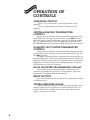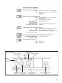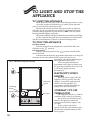
1
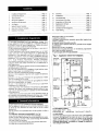
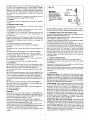
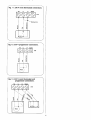
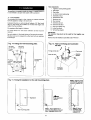
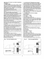
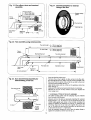
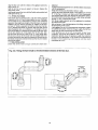
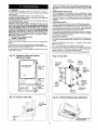
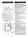
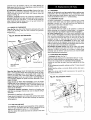
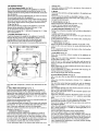
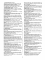
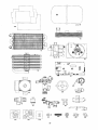
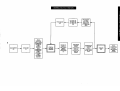
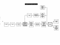
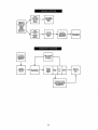
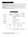
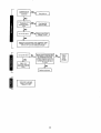
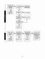
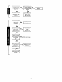
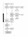
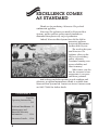
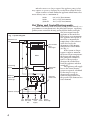
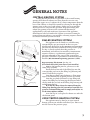
24CDi, 28CDi & 35CDi II
COMBI
APPLIANCE
24CDi Fanned Flued (RSF)
24CDi Balanced Flued (BF)
24CDi Open Flued (OF)
28CDi Fanned Flue (RSF)
35CDi II Fanned Flue (RSF)
G.C. NUMBERS
NATURAL GAS
L.P.G.
47 311 30
47 311 31
47 311 29
47 311 32
47 311 33
47 311 34
47 311 35
47 311 58
47 311 59
USER INSTRUCTIONS &
CUSTOMER CARE GUIDE
EXCELLENCE COMES
AS STANDARD
Thank you for purchasing a Worcester CDi gas-fired
combination appliance.
Worcester CDi appliances are made by Worcester Heat
Systems and the strictest quality control standards are
demanded throughout every stage of production.
Indeed, Worcester Heat Systems have led the field in
innovative appliance
design and performance
for more than 30 years.
The result is that your
new Worcester CDi
appliance offers you the
very best of everything quality, efficiency,
economical running costs,
proven reliability and
value for money.
What’s more, you also
have the assurance of our
no-nonsense 1 year parts
and labour guarantee.
And, to keep your boiler operating at peak condition and
efficiency, an optional maintenance scheme is available from
Worcester Heat Systems Ltd. Contact our Service Contracts team
on 01905 754624 for further details.
CONTENTS
Page No.
Operating Instructions
.................................... 3-11
Fault and Breakdowns 12
Maintenance and
Extended Warranty
Information ............ 13-14
Guarantee Details ... 15-16
2
GENERAL
INFORMATION
GAS SAFETY (INSTALLATION AND USE)
REGULATIONS 1998
It is the law that all gas appliances must be installed by a competent
person in accordance with the above regulations. Failure to install
appliances correctly could lead to prosecution. It is in your interest and
that of safety to ensure compliance with the law. The manufacturers
notes must not be taken, in any way, as overriding statutory obligations.
WARNING: This appliance must be earthed and protected by a 3
amp fuse.
ELECTRICITY SUPPLY: 230V ~ 50Hz
IMPORTANT: To get the best from your Worcester CDi please read
these instructions carefully.
NOTE: In the event of a fault the appliance should not be used
until the fault has been corrected by a competent person.
BENCHMARK
The Benchmark initiative is a code of practice to encourage the
correct installation, commissioning and servicing of domestic central
heating boilers and system equipment.
A 'log book' is dispatched with every appliance, This is a vital
document that needs to be completed by the installer at the time of
installation. It confirms that the boiler has been installed and
commissioned according to the manufacturers instructions.
All CORGI Registered Installers carry a CORGI ID card and have a
registration number. Both should be recorded in your central heating log
book. You can check that your installer is CORGI registered by calling
CORGI on 01256 372300.
Without the completion of the log book, manufacturers may
refuse to respond to a call-out request. It is important that your installer
has given you the fully completed log book.
GENERAL DESCRIPTION
(See Fig.1.)
The WORCESTER CDi MODELS are combined domestic hot water
and central heating appliances. They consist of a gas fired boiler having
a varying output of between:
CH
DHW
24CDi
9.0 - 24kW
9.0 - 24kW
28CDi
9.0 - 24kW
9.0 - 28kW
10.5 - 27.5kW
9.5 - 35.3kW
35CDi II
a heat exchanger to provide domestic hot water via the boiler,
circulating pump and water diverting valve. All the necessary controls to
provide mains fed domestic hot water and central heating.
The appliances are supplied as standard with a manual operating
switch. Alternatively a facia mounted programmer may have been fitted.
The appliances can operate in one of two modes. Hot water only or
hot water and central heating.
Hot Water Mode:
When a demand is made for hot water by opening a tap or shower;
the flow switch will energise the pump and circulate primary hot water
around the boiler and water to water heat exchanger. The burner will
light to its maximum setting.
3
When hot water is no longer required the appliance pump (or fan)
may continue to operate to dissipate the residual heat within the boiler.
A flow restrictor is fitted within the appliance which limits a hot
water delivery rate to a maximum of:
24CDi
28CDi
35CDi II
9.0 (±15%) litres/minute
10.0 (±15%) litres/minute
12.0 (±15%) litres/minute
Hot Water and Central Heating mode:
Fig. 1. System Diagram.
Automatic air
vent
Circulating
pump
Water to
water heat
exchanger
When a demand is made for heating by the system controls (i.e. a
programmer or room thermostat), the pump will energise, circulating
primary water around the heating system and the burner will light.
The heat output from the
appliance in this mode has
been factory set to maximum.
The appliance will operate as
necessary to maintain the
temperature of the radiators
at the level set by the
Gas to water
adjustment of the Heating
heat
Temperature Control Knob.
exchanger
(See Fig. 2.)
If the system no longer
requires output to maintain
the desired room temperature,
Boiler
the burner will extinguish.
The pump will continue to
run for a short period to
dissipate the residual heat
from the appliance and then
switch off.
The appliance will supply
Expansion
heat to the central heating
vessel
system as required. A demand
for hot water at a tap or
shower will override the
central heating function for
Pressure
the period of the domestic hot
relief valve
water demand.
Diverter valve
CH Domestic Domestic CH
Safety
flow hot water
cold return discharge
out
supply
4
GENERAL NOTES
CENTRAL HEATING SYSTEM
During the first few hours of operation of the central heating
system, check that all radiators are being heated at an even rate.
Should the upper area of a radiator be at a lower temperature than the
base of the radiator, it should be vented by releasing air through the
venting screw at the top of each radiator. Make sure your installer
shows you how to carry out the operation. Repeated venting will
reduce the quantity of water in the system and this must be
replenished for safe and satisfactory operation of the appliance.
Should water leaks be found in the system or excessive venting be
required from any radiator, your installer or heating engineer should
be contacted and the system corrected.
SEALED HEATING SYSTEM
Fig. 1a.
The appliance can be fitted to a sealed heating
system which is pre-pressurised. In this case your
installer will advise you on the minimum and maximum
pressure that should be indicated on the pressure gauge.
See Fig. 2. Check regularly that this pressure is
maintained and contact your installer or maintenance
engineer if there is a permanent significant drop in
pressure indicated on the gauge. If the system loses
pressure it should be re-pressurised as instructed by the
installer (N.B. Maximum operating pressure 2.5 bar).
Grey
Knob
Filling Key
Re-pressurising The System (See Fig. 1a).
(If in doubt leave this procedure to your installer).
Remove the bottom panel to gain access to the
filling loop assembly.
Insert the bayonet end of the filling key into the
corresponding cut outs in the filling loop housing and
twist to lock the key in place.
Turn the grey knob anti-clockwise to allow water
ingress and fill until the required pressure is reached.
Turn the grey knob clockwise to stop filling and
remove the filling key by lining up the bayonet end of
the key with the cut outs in the filling loop housing and
withdrawing the key.
N.B. The key must always be removed from the
filling loop housing after the system has been filled to
prevent accidental filling and to comply with Bylaw 14
of the Water Bylaws Scheme.
Store the key in a safe place for future use and refit
the bottom panel.
OPEN VENTED HEATING SYSTEM
The appliance may be fitted to an open vented
heating system your installer will advise you. There is no
need to observe the pressure gauge.
5
CLEARANCES
24,28CDi RSF
35CDi II
24CDi OF
24CDiBF
Left-hand side
Right-hand side
In Front
Above
10
10
600
180
10
10
600
180
10
10
600
300
10
10
600
100
Below
200
200
200
200
Minimum clearances in millimetres.
Your installer will have provided adequate space around the
appliance for safety and servicing. Do not restrict this space by the
addition of cupboards, shelves etc. close to the appliance.
ROOM THERMOSTAT
A room thermostat may be fitted for control of the central heating
temperature. It will be located in one room of the home. The method
of setting a room thermostat varies with the type and manufacture.
Refer to the instructions supplied with the room thermostat.
THERMOSTATIC RADIATOR VALVES
If thermostatic radiator valves are fitted to the system then they
must conform to the requirements of BS2767:10. It is advisable to leave
one valve permanently set at maximum to prevent the boiler short
cycling.
SHOWERS, BIDETS, TAPS AND MIXING
VALVES
Standard hot and cold taps and mixing valves used with the
appliance must be suitable for operating at mains pressure.
Thermostatically controlled shower valves will guard against the flow
of water at too high a temperature.
If using a pressure equalising valve, set the Domestic Hot Water
temperature control knob to the ‘MAX’ position.
Hot and cold mains fed water can be supplied direct to an
overrim flushing bidet subject to local water company requirements.
With all mains fed systems the flow of water from the individual
taps will vary with the number of outlets operated simultaneously
and the cold water mains supply pressure to the property. Flow
balancing using ‘Ball-o-Fix’ type valves is recommended to avoid an
excessive reduction in flow to individual outlets.
For further information contact Worcester Heat Systems
Technical Helpline. 08705 266241
HOT AND COLD FLOW
The flow of water demanded from both hot and cold service
outlets is dependent upon mains supply, it may not be possible in
some installations to operate all outlets simultaneously.
WATER MAINS FAILURE
It is important to note that in the event of a mains water supply
failure, no tap water will be available until the mains supply is
restored. The appliance can still be used for heating provided that the
system is of the sealed system type. Open vent central heating
systems should be turned off until the supply is restored.
USE IN HARD WATER AREAS
6
Normally there is no need for scale protection. However, in areas
of exceptionally hard water supply it is recommended that an In-Line
scale inhibitor be fitted.
Installation should be strictly in accordance with the
requirements of the local Water Company. An isolating valve to
facilitate servicing should be incorporated
The water hardness may be determined using the standard test
paper or by reference to the local Water Company.
Further information may be obtained from Worcester Heat
Systems Technical Helpline.
AIR SUPPLY FOR OPEN FLUED (O.F.)
APPLIANCES
Your installer will have made arrangements for an adequate
supply of fresh air to the appliance. Fresh air is required for
combustion. Do not block up any air ways which may be let into a wall
or door. Do not hang clothes or other combustible materials over the
appliance or against the flue pipe.
NOTE: Do not place anything on top of the appliance. If the
appliance is fitted in a compartment do not use the compartment for
storage purposes unless it conforms to the requirements of
BS 6798:1987: Section 6. In particular, the flue pipe should not pass
through an airing cupboard space unless protected by a guard (such as
wire mesh) concentrically spaced 13mm (1/2in), as described in BS 6798:1987.
VENTILATION OF BALANCED FLUED (BF)
AND ROOM SEALED FANNED FLUE (RSF)
APPLIANCES
These are room sealed appliances and any ventilation openings
in a wall or door must not be obstructed. Do not allow the flue
terminal fitted on the outside wall to become obstructed or damaged.
NOTE: Do not place anything on top of the appliance. If the
appliance is fitted in a compartment do not use the compartment for
storage purposes unless it conforms to the requirements of
BS 6798:1987: Section 6. It is essential that the airing space is
separated from the boiler space by a perforated non-combustible
partition as described in BS 6798:1987.
CIRCULATING PUMP
This may be fitted with a speed adjuster. If so it will be factory
set at maximum and should not be changed.
FROST PRECAUTIONS
If the appliance is not to be used for a long period of time and
there is a likelihood of freezing, then the appliance should be drained.
The Worcester Heat Systems Technical Helpline will advise you on
suitable frost precautions. For short periods, the built-in frost
protection of the appliance will be adequate.
SERVICE
Annual servicing is important to ensure continuing high efficiency and
long life of your appliance. Suitable servicing arrangements should be made
with a competent third party. In the event of any difficulty in making
suitable service arrangements, Worcester Heat Systems Ltd. will be happy to
discuss regular servicing and offer a comprehensive maintenance contract.
IMPORTANT: Do not touch or adjust any sealed compontent.
WARNING
If a gas leak exists, or is suspected, turn off the gas supply to the
appliance at the service cock and consult your local service engineer.
Do not touch any electrical switches to turn them either on or off.
Open all windows and doors. Do not smoke. Extinguish all naked lights.
CLEANING
Do not use abrasive cleaners on the outer casing. Use a damp
cloth and a little detergent.
7
OPERATION OF
CONTROLS
OPERATING SWITCH
In the ‘ ’ position there is no mains electricity to the
appliance.
In the ‘I’ position mains electricity is connected to the
appliance.
CENTRAL HEATING TEMPERATURE
CONTROL
The position of this knob will determine the temperature of the
water delivered to the radiators between the ‘I’ and ‘MAX’ position.
When the knob is turned anti-clockwise past the ‘I’ position towards
the ‘ ’ (Summer Position), then the appliance will operate in the
HOT WATER mode only and no heat will be delivered to the radiators.
DOMESTIC HOT WATER TEMPERATURE
CONTROL
The position of this knob will determine the temperature of the
water delivered at the domestic hot water taps between the ‘ ’ and
the ‘MAX’ position.
By slightly reducing the flow of domestic water from the tap, the
delivery temperature of the water will be further increased. This is of
particular advantage in the winter, for example to increase bath water
temperature. Also this will provide an added advantage of reducing
the delay before hot water is obtained.
FACIA MOUNTED PROGRAMMER (if fitted)
Your installer may have mounted either a mechanical or an
electronic programmer into the facia of your appliance. Operating
instructions are supplied with the programmer.
RESET BUTTON
Press this button in for five seconds if any of the indicator lights
are flashing slowly.
SYSTEM PRESSURE GAUGE
The red needle has been set to show the sealed system pressure
which is required for the appliance to operate effectively. The grey
needle will show the actual pressure in the system. This does not
apply to any open vent system.
8
INDICATOR LIGHTS
Mains electricity indicator:
OFF : No mains electricity to the appliance
ON : Mains electricity is connected to the
appliance
Central heating demand indicator:
OFF : No demand for heat to the central
heating circuit
ON : Central heating demand
FLASHING SLOW : Ignition lockout
(once per second)
FLASHING FAST : Appliance fault (other than ignition
(five times per second) lockout)
Domestic hot water demand indicator:
OFF : No demand for domestic hot water
ON : Domestic hot water demand
FLASHING FAST : Air flow fault (RSF). Flue gas spillage (OF)
(five times per second)
Central heating and domestic hot water demand indicators:
BOTH FLASHING SLOW : Overheat cut-off
(once per second)
Flame detection indicator:
OFF : Burner off
ON : Burner on
Fig. 2. Controls.
Central heating
demand indicator
DHW demand
indicator Flame detection
Reset
indicator
button
Mains
electricity
indicator
Operating CH temperature
switch
control knob
DHW temperature
control knob
Sealed system pressure
gauge
9
TO LIGHT AND STOP THE
APPLIANCE
TO LIGHT THE APPLIANCE
Check that the water valves to the central heating circuit are open.
On sealed systems check that the grey needle on the pressure
gauge is not below the required pressure.
Switch on the mains electricity. The green power on indicator
will light. Set the room thermostat, if fitted, to maximum. Turn the
central heating temperature control knob to ‘MAX’. The red central
heating demand indicator will light.
The burner will light and the red flame detection indicator will light.
Set the central heating and hot water temperature control knobs
and the room thermostat, if fitted, to the desired temperature.
TO STOP THE APPLIANCE
For Short Periods
Turn the central heating temperature control knob fully anticlockwise to the ‘ ’ position.
For Long Periods
Turn the operating switch to the ‘ ’ position. Switch off the
mains electricity.
A facia mounted electronic programmer will retain its settings for
about two weeks, after which it will return to the factory set
programme. The display will disappear
after approximately 12 hours.
Fig. 3. CDi with front panel removed.
A facia mounted mechanical
programmer will require resetting once
the operating switch has been set to ‘O’,
or the mains supply has been
Clip
disconnected.
ELECTRICITY SUPPLY
FAILURE
Expansion
vessel
Circulating
pump
Locating peg
Gas valve
10
If the electricity supply fails the
appliance will not operate. Once the
supply is restored the appliance will
return to normal operation. If a
programmer is fitted, check that the
settings have been maintained.
OVERHEAT CUT-OFF
THERMOSTAT
The appliance will enter a lockout
condition in the event of overheating.
An overheat cut-off thermostat is
fitted to the appliance which will
interrupt the electricity supply to the
gas valve.
If the overheat cut-off has
operated, both the central heating and
the hot water demand indicators will
flash together.