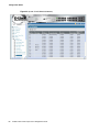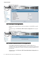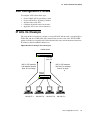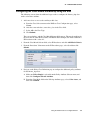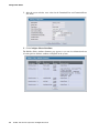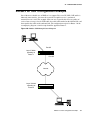
1
Configuration Guide
Product Model : DWS-3000 Series
Unified Wired & Wireless Access System
Release 3.0
February 2011
©Copyright 2011. All rights reserved.
Configuration Guide
2
© 2001- 2011 D-Link Corporation. All Rights Reserved.
Table of Contents
List of Figures. . . . . . . . . . . . . . . . . . . . . . . . . . . . . . . . . . . . . . . . . . . 9
List of Tables . . . . . . . . . . . . . . . . . . . . . . . . . . . . . . . . . . . . . . . . . . 13
About This Book . . . . . . . . . . . . . . . . . . . . . . . . . . . . . . . . . . . . . . . 15
Document Organization . . . . . . . . . . . . . . . . . . . . . . . . . . . . . . . . . . . . . . .
CLI/Web Examples - Slot/Port Designations . . . . . . . . . . . . . . . . . . . . . . .
Audience . . . . . . . . . . . . . . . . . . . . . . . . . . . . . . . . . . . . . . . . . . . . . . . . . . .
CLI Documentation. . . . . . . . . . . . . . . . . . . . . . . . . . . . . . . . . . . . . . . . . . .
15
16
16
16
1 Getting Started . . . . . . . . . . . . . . . . . . . . . . . . . . . . . . . . . . . . . . 17
In-Band and Out-of-Band Connectivity . . . . . . . . . . . . . . . . . . . . . . . . . . .
17
Configuring for In-Band Connectivity . . . . . . . . . . . . . . . . . . . . . . . . . . . . . .
Configuring for Out-of-Band Connectivity . . . . . . . . . . . . . . . . . . . . . . . . . . .
17
19
Starting the Switch . . . . . . . . . . . . . . . . . . . . . . . . . . . . . . . . . . . . . . . . . . .
Initial Configuration . . . . . . . . . . . . . . . . . . . . . . . . . . . . . . . . . . . . . . . . . .
Unified Switch Installation . . . . . . . . . . . . . . . . . . . . . . . . . . . . . . . . . . . . .
20
20
21
Quick Starting the Networking Device . . . . . . . . . . . . . . . . . . . . . . . . . . . . . .
System Information and System Setup. . . . . . . . . . . . . . . . . . . . . . . . . . . . . . .
21
21
2 Using the Web Interface. . . . . . . . . . . . . . . . . . . . . . . . . . . . . . . 27
Configuring for Web Access . . . . . . . . . . . . . . . . . . . . . . . . . . . . . . . . . . . .
Starting the Web Interface. . . . . . . . . . . . . . . . . . . . . . . . . . . . . . . . . . . . . .
27
28
Web Page Layout. . . . . . . . . . . . . . . . . . . . . . . . . . . . . . . . . . . . . . . . . . . . . . .
Configuring an SNMP V3 User Profile. . . . . . . . . . . . . . . . . . . . . . . . . . . . . .
Command Buttons . . . . . . . . . . . . . . . . . . . . . . . . . . . . . . . . . . . . . . . . . . . . . .
Switching the Date/Time Zone. . . . . . . . . . . . . . . . . . . . . . . . . . . . . . . . . . . . .
28
29
30
31
3 Virtual LANs . . . . . . . . . . . . . . . . . . . . . . . . . . . . . . . . . . . . . . . . 33
VLAN Configuration Example . . . . . . . . . . . . . . . . . . . . . . . . . . . . . . . . . .
34
Configuring a Guest VLAN . . . . . . . . . . . . . . . . . . . . . . . . . . . . . . . . . . . . . . .
Configuring Dynamic VLAN Assignments . . . . . . . . . . . . . . . . . . . . . . . . . . .
34
34
CLI Examples . . . . . . . . . . . . . . . . . . . . . . . . . . . . . . . . . . . . . . . . . . . . . . .
35
Example #1: Create Two VLANs . . . . . . . . . . . . . . . . . . . . . . . . . . . . . . . . . . .
Example #2: Assign Ports to VLAN2 . . . . . . . . . . . . . . . . . . . . . . . . . . . . . . .
Example #3: Assign Ports to VLAN3 . . . . . . . . . . . . . . . . . . . . . . . . . . . . . . .
Example #4: Assign VLAN3 as the Default VLAN . . . . . . . . . . . . . . . . . . . . .
Example #5: Assign IP Addresses to VLAN 2 . . . . . . . . . . . . . . . . . . . . . . . . .
35
35
35
36
36
Web Interface . . . . . . . . . . . . . . . . . . . . . . . . . . . . . . . . . . . . . . . . . . . . . . .
Private Edge VLANs . . . . . . . . . . . . . . . . . . . . . . . . . . . . . . . . . . . . . . . . . .
36
37
CLI Example . . . . . . . . . . . . . . . . . . . . . . . . . . . . . . . . . . . . . . . . . . . . . . . . . .
38
Voice VLAN . . . . . . . . . . . . . . . . . . . . . . . . . . . . . . . . . . . . . . . . . . . . . . . . .
38
3
Configuration Guide
4 Storm Control. . . . . . . . . . . . . . . . . . . . . . . . . . . . . . . . . . . . . . . .41
CLI Example . . . . . . . . . . . . . . . . . . . . . . . . . . . . . . . . . . . . . . . . . . . . . . . .
41
Example #1: Set Broadcast Storm Control for All Interfaces . . . . . . . . . . . . .
Example #2: Set Multicast Storm Control for All Interfaces . . . . . . . . . . . . . .
Example #3: Set Unicast Storm Control for All Interfaces . . . . . . . . . . . . . . .
41
42
42
Web Interface . . . . . . . . . . . . . . . . . . . . . . . . . . . . . . . . . . . . . . . . . . . . . . .
43
5 Trunking (Link Aggregation) . . . . . . . . . . . . . . . . . . . . . . . . . . .45
CLI Example . . . . . . . . . . . . . . . . . . . . . . . . . . . . . . . . . . . . . . . . . . . . . . . .
45
Example 1: Create two port-channels: . . . . . . . . . . . . . . . . . . . . . . . . . . . . . .
Example 2: Add the physical ports to the port-channels: . . . . . . . . . . . . . . . .
Example 3: Enable both port-channels: . . . . . . . . . . . . . . . . . . . . . . . . . . . . .
46
47
47
Web Interface Configuration — LAGs/Port-channels . . . . . . . . . . . . . . . .
48
6 IGMP Snooping . . . . . . . . . . . . . . . . . . . . . . . . . . . . . . . . . . . . . .49
Overview . . . . . . . . . . . . . . . . . . . . . . . . . . . . . . . . . . . . . . . . . . . . . . . . . . .
CLI Examples . . . . . . . . . . . . . . . . . . . . . . . . . . . . . . . . . . . . . . . . . . . . . . .
49
49
Example #1: show igmpsnooping . . . . . . . . . . . . . . . . . . . . . . . . . . . . . . . . . .
Example #2: show mac-address-table igmpsnooping . . . . . . . . . . . . . . . . . . .
Example #3: set igmp (Global Config Mode) . . . . . . . . . . . . . . . . . . . . . . . . .
Example #4: set igmp (Interface Config Mode). . . . . . . . . . . . . . . . . . . . . . . .
49
50
50
50
Web Examples . . . . . . . . . . . . . . . . . . . . . . . . . . . . . . . . . . . . . . . . . . . . . . .
51
7 Port Mirroring . . . . . . . . . . . . . . . . . . . . . . . . . . . . . . . . . . . . . . .57
Overview . . . . . . . . . . . . . . . . . . . . . . . . . . . . . . . . . . . . . . . . . . . . . . . . . . .
CLI Examples . . . . . . . . . . . . . . . . . . . . . . . . . . . . . . . . . . . . . . . . . . . . . . .
57
57
Example #1: Set up a Port Mirroring Session . . . . . . . . . . . . . . . . . . . . . . . . .
Example #2: Show the Port Mirroring Session . . . . . . . . . . . . . . . . . . . . . . . .
Example #3: Show the Status of All Ports . . . . . . . . . . . . . . . . . . . . . . . . . . . .
Example #4: Show the Status of the Source and Destination Ports. . . . . . . . .
57
58
58
58
Web Examples . . . . . . . . . . . . . . . . . . . . . . . . . . . . . . . . . . . . . . . . . . . . . . .
59
8 Link Layer Discovery Protocol. . . . . . . . . . . . . . . . . . . . . . . . . .61
CLI Examples . . . . . . . . . . . . . . . . . . . . . . . . . . . . . . . . . . . . . . . . . . . . . . .
61
Example #1: Set Global LLDP Parameters. . . . . . . . . . . . . . . . . . . . . . . . . . .
Example #2: Set Interface LLDP Parameters . . . . . . . . . . . . . . . . . . . . . . . . .
Example #3: Show Global LLDP Parameters . . . . . . . . . . . . . . . . . . . . . . . . .
Example #4 Show Interface LLDP Parameters . . . . . . . . . . . . . . . . . . . . . . . .
61
62
62
62
Using the Web Interface to Configure LLDP . . . . . . . . . . . . . . . . . . . . . . .
63
9 Denial of Service Attack Protection . . . . . . . . . . . . . . . . . . . . . .67
Overview . . . . . . . . . . . . . . . . . . . . . . . . . . . . . . . . . . . . . . . . . . . . . . . . . . .
CLI Examples . . . . . . . . . . . . . . . . . . . . . . . . . . . . . . . . . . . . . . . . . . . . . . .
Web Interface . . . . . . . . . . . . . . . . . . . . . . . . . . . . . . . . . . . . . . . . . . . . . . .
67
67
68
10 Port Routing . . . . . . . . . . . . . . . . . . . . . . . . . . . . . . . . . . . . . . . . .69
Port Routing Configuration . . . . . . . . . . . . . . . . . . . . . . . . . . . . . . . . . . . .
4
© 2001- 2011 D-Link Corporation. All Rights Reserved.
69
CLI Examples . . . . . . . . . . . . . . . . . . . . . . . . . . . . . . . . . . . . . . . . . . . . . . .
70
Example 1. Enabling Routing for the Switch . . . . . . . . . . . . . . . . . . . . . . . . .
Example 2. Enabling Routing for Ports on the Switch . . . . . . . . . . . . . . . . . .
70
70
Using the Web Interface to Configure Routing . . . . . . . . . . . . . . . . . . . . . .
72
11 VLAN Routing . . . . . . . . . . . . . . . . . . . . . . . . . . . . . . . . . . . . . . 73
VLAN Routing Configuration . . . . . . . . . . . . . . . . . . . . . . . . . . . . . . . . . . .
CLI Examples . . . . . . . . . . . . . . . . . . . . . . . . . . . . . . . . . . . . . . . . . . . . . . .
73
73
Example 1: Create Two VLANs . . . . . . . . . . . . . . . . . . . . . . . . . . . . . . . . . . . .
Example 2: Set Up VLAN Routing for the VLANs and the Switch. . . . . . . . . .
74
75
Using the Web Interface to Configure VLAN Routing . . . . . . . . . . . . . . . .
76
12 Virtual Router Redundancy Protocol . . . . . . . . . . . . . . . . . . . . 79
CLI Examples . . . . . . . . . . . . . . . . . . . . . . . . . . . . . . . . . . . . . . . . . . . . . . .
79
Example 1: Configuring VRRP on the Switch as a Master Router . . . . . . . . .
Example 2: Configuring VRRP on the Switch as a Backup Router . . . . . . . .
80
81
Using the Web Interface to Configure VRRP . . . . . . . . . . . . . . . . . . . . . . .
82
13 Proxy Address Resolution Protocol (ARP). . . . . . . . . . . . . . . . 85
Overview . . . . . . . . . . . . . . . . . . . . . . . . . . . . . . . . . . . . . . . . . . . . . . . . . . .
CLI Examples . . . . . . . . . . . . . . . . . . . . . . . . . . . . . . . . . . . . . . . . . . . . . . .
85
85
Example #1 show ip interface . . . . . . . . . . . . . . . . . . . . . . . . . . . . . . . . . . . . .
Example #2: ip proxy-arp . . . . . . . . . . . . . . . . . . . . . . . . . . . . . . . . . . . . . . . .
85
86
Web Example. . . . . . . . . . . . . . . . . . . . . . . . . . . . . . . . . . . . . . . . . . . . . . . .
86
14 Routing Information Protocol (RIP). . . . . . . . . . . . . . . . . . . . . 87
Overview . . . . . . . . . . . . . . . . . . . . . . . . . . . . . . . . . . . . . . . . . . . . . . . . . . .
87
RIP Configuration . . . . . . . . . . . . . . . . . . . . . . . . . . . . . . . . . . . . . . . . . . . . . .
87
RIP Interface Configuration . . . . . . . . . . . . . . . . . . . . . . . . . . . . . . . . . . . .
RIP Route Redistribution Configuration . . . . . . . . . . . . . . . . . . . . . . . . . .
88
88
15 Access Control Lists (ACLs) . . . . . . . . . . . . . . . . . . . . . . . . . . . 91
Overview . . . . . . . . . . . . . . . . . . . . . . . . . . . . . . . . . . . . . . . . . . . . . . . . . . .
91
Limitations. . . . . . . . . . . . . . . . . . . . . . . . . . . . . . . . . . . . . . . . . . . . . . . . . . . .
91
MAC ACLs . . . . . . . . . . . . . . . . . . . . . . . . . . . . . . . . . . . . . . . . . . . . . . . . .
IP ACLs. . . . . . . . . . . . . . . . . . . . . . . . . . . . . . . . . . . . . . . . . . . . . . . . . . . .
ACL Configuration Process . . . . . . . . . . . . . . . . . . . . . . . . . . . . . . . . . . . .
IP ACL CLI Example . . . . . . . . . . . . . . . . . . . . . . . . . . . . . . . . . . . . . . . . .
92
92
93
93
Example #1: Create ACL 179 and Define an ACL Rule . . . . . . . . . . . . . . . . .
Example #2: Define the Second Rule for ACL 179 . . . . . . . . . . . . . . . . . . . . .
Example #3: Apply the rule to Inbound Traffic on Port 0/2 . . . . . . . . . . . . . .
94
94
94
MAC ACL CLI Examples . . . . . . . . . . . . . . . . . . . . . . . . . . . . . . . . . . . . . .
94
Example #4: Set up a MAC Access List . . . . . . . . . . . . . . . . . . . . . . . . . . . . .
Example #5: Specify MAC ACL Attributes . . . . . . . . . . . . . . . . . . . . . . . . . . .
Example #6 Configure MAC Access Group . . . . . . . . . . . . . . . . . . . . . . . . . .
Example #7 Set up an ACL with Permit Action. . . . . . . . . . . . . . . . . . . . . . . .
94
95
96
97
5
Configuration Guide
Example #8: Show MAC Access Lists . . . . . . . . . . . . . . . . . . . . . . . . . . . . . . .
97
Web Examples . . . . . . . . . . . . . . . . . . . . . . . . . . . . . . . . . . . . . . . . . . . . . . .
98
MAC ACL Web Pages . . . . . . . . . . . . . . . . . . . . . . . . . . . . . . . . . . . . . . . . . . . 98
IP ACL Web Pages . . . . . . . . . . . . . . . . . . . . . . . . . . . . . . . . . . . . . . . . . . . . . 101
16 802.1X Network Access Control . . . . . . . . . . . . . . . . . . . . . . . .105
802.1x Network Access Control Example . . . . . . . . . . . . . . . . . . . . . . . . .
Guest VLAN . . . . . . . . . . . . . . . . . . . . . . . . . . . . . . . . . . . . . . . . . . . . . . .
106
107
Configuring the Guest VLAN by Using the CLI. . . . . . . . . . . . . . . . . . . . . . .
Configuring the Guest VLAN by Using the Web Interface. . . . . . . . . . . . . . .
107
108
Configuring Dynamic VLAN Assignment . . . . . . . . . . . . . . . . . . . . . . . . .
109
17 Captive Portal . . . . . . . . . . . . . . . . . . . . . . . . . . . . . . . . . . . . . . 111
Web Example. . . . . . . . . . . . . . . . . . . . . . . . . . . . . . . . . . . . . . . . . . . . . . .
CLI Example . . . . . . . . . . . . . . . . . . . . . . . . . . . . . . . . . . . . . . . . . . . . . . .
Customizing the Captive Portal Web Page . . . . . . . . . . . . . . . . . . . . . . . .
Client Authentation Logout Request . . . . . . . . . . . . . . . . . . . . . . . . . . . . .
Captive Port Rate Limiting . . . . . . . . . . . . . . . . . . . . . . . . . . . . . . . . . . . .
111
113
113
116
117
18 Port Security. . . . . . . . . . . . . . . . . . . . . . . . . . . . . . . . . . . . . . . . 119
Overview . . . . . . . . . . . . . . . . . . . . . . . . . . . . . . . . . . . . . . . . . . . . . . . . . .
Operation . . . . . . . . . . . . . . . . . . . . . . . . . . . . . . . . . . . . . . . . . . . . . . . . .
CLI Examples . . . . . . . . . . . . . . . . . . . . . . . . . . . . . . . . . . . . . . . . . . . . . .
119
119
120
Example #1: show port security. . . . . . . . . . . . . . . . . . . . . . . . . . . . . . . . . . .
Example #2: show port security on a specific interface . . . . . . . . . . . . . . . .
Example #3: (Config) port security . . . . . . . . . . . . . . . . . . . . . . . . . . . . . . . .
120
120
120
Web Examples . . . . . . . . . . . . . . . . . . . . . . . . . . . . . . . . . . . . . . . . . . . . . .
121
19 RADIUS . . . . . . . . . . . . . . . . . . . . . . . . . . . . . . . . . . . . . . . . . . .125
Client Name in Local MAC Authentication List . . . . . . . . . . . . . . . . . . . .
RADIUS Fail-through and Failover Server Support . . . . . . . . . . . . . . . .
RADIUS Configuration Examples . . . . . . . . . . . . . . . . . . . . . . . . . . . . . .
125
126
127
Configuring RADIUS for Wired Clients. . . . . . . . . . . . . . . . . . . . . . . . . . . . .
Configuring RADIUS Fail-through on a Managed AP . . . . . . . . . . . . . . . . .
127
131
20 TACACS+ . . . . . . . . . . . . . . . . . . . . . . . . . . . . . . . . . . . . . . . . . .133
TACACS+ Configuration Example . . . . . . . . . . . . . . . . . . . . . . . . . . . . . .
133
Configuring TACACS+ by Using CLI Commands. . . . . . . . . . . . . . . . . . . . .
Configuring TACACS+ by Using the Web Interface . . . . . . . . . . . . . . . . . . .
134
135
21 Class of Service Queuing. . . . . . . . . . . . . . . . . . . . . . . . . . . . . .139
6
Ingress Port Configuration . . . . . . . . . . . . . . . . . . . . . . . . . . . . . . . . . . . .
139
Trusted and Untrusted Ports/CoS Mapping Table . . . . . . . . . . . . . . . . . . . . .
CoS Mapping Table for Trusted Ports . . . . . . . . . . . . . . . . . . . . . . . . . . . . . .
139
140
Egress Port Configuration - Traffic Shaping . . . . . . . . . . . . . . . . . . . . . .
Queue Configuration . . . . . . . . . . . . . . . . . . . . . . . . . . . . . . . . . . . . . . . .
140
140
© 2001- 2011 D-Link Corporation. All Rights Reserved.
Queue Management Type . . . . . . . . . . . . . . . . . . . . . . . . . . . . . . . . . . . . .
CLI Examples . . . . . . . . . . . . . . . . . . . . . . . . . . . . . . . . . . . . . . . . . . . . . .
Web Examples . . . . . . . . . . . . . . . . . . . . . . . . . . . . . . . . . . . . . . . . . . . . . .
140
140
143
22 Differentiated Services . . . . . . . . . . . . . . . . . . . . . . . . . . . . . . . 147
CLI Example . . . . . . . . . . . . . . . . . . . . . . . . . . . . . . . . . . . . . . . . . . . . . . .
148
DiffServ Inbound Configuration . . . . . . . . . . . . . . . . . . . . . . . . . . . . . . . . . .
Adding Color-Aware Policing Attribute . . . . . . . . . . . . . . . . . . . . . . . . . . . .
148
150
Using the Web Interface to Configure Diffserv. . . . . . . . . . . . . . . . . . . . .
151
Configuring the Color-Aware Attribute by Using the Web . . . . . . . . . . . . . .
159
DiffServ for VoIP Configuration Example . . . . . . . . . . . . . . . . . . . . . . . .
161
Configuring DiffServ VoIP Support Example . . . . . . . . . . . . . . . . . . . . . . . .
162
23 DHCP Filtering . . . . . . . . . . . . . . . . . . . . . . . . . . . . . . . . . . . . . 163
Overview . . . . . . . . . . . . . . . . . . . . . . . . . . . . . . . . . . . . . . . . . . . . . . . . . .
Limitations . . . . . . . . . . . . . . . . . . . . . . . . . . . . . . . . . . . . . . . . . . . . . . . .
CLI Examples . . . . . . . . . . . . . . . . . . . . . . . . . . . . . . . . . . . . . . . . . . . . . .
163
163
164
Example #1: Enable DHCP Filtering for the Switch . . . . . . . . . . . . . . . . . .
Example #2: Enable DHCP Filtering for an Interface . . . . . . . . . . . . . . . . .
Example #3: Show DHCP Filtering Configuration . . . . . . . . . . . . . . . . . . .
164
164
164
Web Examples . . . . . . . . . . . . . . . . . . . . . . . . . . . . . . . . . . . . . . . . . . . . . .
164
24 Traceroute . . . . . . . . . . . . . . . . . . . . . . . . . . . . . . . . . . . . . . . . . 167
CLI Example . . . . . . . . . . . . . . . . . . . . . . . . . . . . . . . . . . . . . . . . . . . . . . .
167
25 Configuration Scripting . . . . . . . . . . . . . . . . . . . . . . . . . . . . . . 169
Overview . . . . . . . . . . . . . . . . . . . . . . . . . . . . . . . . . . . . . . . . . . . . . . . . . .
Considerations . . . . . . . . . . . . . . . . . . . . . . . . . . . . . . . . . . . . . . . . . . . . .
CLI Examples . . . . . . . . . . . . . . . . . . . . . . . . . . . . . . . . . . . . . . . . . . . . . .
169
169
169
Example #1: script. . . . . . . . . . . . . . . . . . . . . . . . . . . . . . . . . . . . . . . . . . . . .
Example #2: script list and script delete . . . . . . . . . . . . . . . . . . . . . . . . . . . .
Example #3: script apply running-config.scr . . . . . . . . . . . . . . . . . . . . . . . .
Example #4: show running-config . . . . . . . . . . . . . . . . . . . . . . . . . . . . . . . .
Example #5: copy nvram: script . . . . . . . . . . . . . . . . . . . . . . . . . . . . . . . . . .
Example #6: script validate running-config.scr . . . . . . . . . . . . . . . . . . . . . .
Example #7: Validate another Configuration Script. . . . . . . . . . . . . . . . . . .
169
170
170
170
171
171
172
26 Outbound Telnet . . . . . . . . . . . . . . . . . . . . . . . . . . . . . . . . . . . . 173
Overview . . . . . . . . . . . . . . . . . . . . . . . . . . . . . . . . . . . . . . . . . . . . . . . . . .
CLI Examples . . . . . . . . . . . . . . . . . . . . . . . . . . . . . . . . . . . . . . . . . . . . . .
173
173
Example #1: show network . . . . . . . . . . . . . . . . . . . . . . . . . . . . . . . . . . . . . .
Example #2: show telnet . . . . . . . . . . . . . . . . . . . . . . . . . . . . . . . . . . . . . . . .
Example #3: transport output telnet . . . . . . . . . . . . . . . . . . . . . . . . . . . . . . .
Example #4: session-limit and session-timeout. . . . . . . . . . . . . . . . . . . . . . .
174
174
174
174
Web Example. . . . . . . . . . . . . . . . . . . . . . . . . . . . . . . . . . . . . . . . . . . . . . .
175
7
Configuration Guide
27 Pre-Login Banner . . . . . . . . . . . . . . . . . . . . . . . . . . . . . . . . . . .177
Overview . . . . . . . . . . . . . . . . . . . . . . . . . . . . . . . . . . . . . . . . . . . . . . . . . .
CLI Example . . . . . . . . . . . . . . . . . . . . . . . . . . . . . . . . . . . . . . . . . . . . . . .
177
177
28 Simple Network Time Protocol (SNTP). . . . . . . . . . . . . . . . . .179
Overview . . . . . . . . . . . . . . . . . . . . . . . . . . . . . . . . . . . . . . . . . . . . . . . . . .
CLI Examples . . . . . . . . . . . . . . . . . . . . . . . . . . . . . . . . . . . . . . . . . . . . . .
179
179
Example #1: show sntp . . . . . . . . . . . . . . . . . . . . . . . . . . . . . . . . . . . . . . . . .
Example #2: show sntp client . . . . . . . . . . . . . . . . . . . . . . . . . . . . . . . . . . . .
Example #3: show sntp server . . . . . . . . . . . . . . . . . . . . . . . . . . . . . . . . . . . .
Example #4: configure sntp . . . . . . . . . . . . . . . . . . . . . . . . . . . . . . . . . . . . . .
Example #5: configure sntp client mode . . . . . . . . . . . . . . . . . . . . . . . . . . . .
Example #6: configuring sntp server. . . . . . . . . . . . . . . . . . . . . . . . . . . . . . .
Example #7: configure sntp client port . . . . . . . . . . . . . . . . . . . . . . . . . . . . .
179
179
180
180
180
181
181
Web Interface Examples . . . . . . . . . . . . . . . . . . . . . . . . . . . . . . . . . . . . . .
181
29 Syslog . . . . . . . . . . . . . . . . . . . . . . . . . . . . . . . . . . . . . . . . . . . . .185
Overview . . . . . . . . . . . . . . . . . . . . . . . . . . . . . . . . . . . . . . . . . . . . . . . . . .
185
Interpreting Log Files . . . . . . . . . . . . . . . . . . . . . . . . . . . . . . . . . . . . . . . . . .
185
CLI Examples . . . . . . . . . . . . . . . . . . . . . . . . . . . . . . . . . . . . . . . . . . . . . .
186
Example #1: show logging. . . . . . . . . . . . . . . . . . . . . . . . . . . . . . . . . . . . . . .
Example #2: show logging buffered. . . . . . . . . . . . . . . . . . . . . . . . . . . . . . . .
Example #3: show logging traplogs . . . . . . . . . . . . . . . . . . . . . . . . . . . . . . .
Example 4: show logging hosts . . . . . . . . . . . . . . . . . . . . . . . . . . . . . . . . . . .
Example #5: logging port configuration . . . . . . . . . . . . . . . . . . . . . . . . . . . .
186
186
187
187
188
Web Examples . . . . . . . . . . . . . . . . . . . . . . . . . . . . . . . . . . . . . . . . . . . . . .
189
30 Port Description . . . . . . . . . . . . . . . . . . . . . . . . . . . . . . . . . . . . .191
8
CLI Example . . . . . . . . . . . . . . . . . . . . . . . . . . . . . . . . . . . . . . . . . . . . . . .
191
Example #1: Enter a Description for a Port . . . . . . . . . . . . . . . . . . . . . . . . .
Example #2: Show the Port Description . . . . . . . . . . . . . . . . . . . . . . . . . . . .
191
191
Configuring Port Description with the Web Interface . . . . . . . . . . . . . . .
192
© 2001- 2011 D-Link Corporation. All Rights Reserved.
List of Figures
List of Figures
Figure 1. Web Interface Panel-Example .............................................................. 28
Figure 2. Web Interface Panel-Example .............................................................. 29
Figure 3. Configuring an SNMP V3 User Profile ................................................ 29
Figure 4. System Description Page....................................................................... 31
Figure 5. VLAN Example Network Diagram....................................................... 34
Figure 6. VLAN Configuration ............................................................................ 36
Figure 7. VLAN Port Configuration..................................................................... 37
Figure 8. Voice VLAN Configuration .................................................................. 39
Figure 9. Port Configuration (Storm Control) ...................................................... 43
Figure 10. LAG/Port-channel Example Network Diagram .................................. 46
Figure 11. Trunking Configuration....................................................................... 48
Figure 12. IGMP Snooping - Global Configuration and Status Page................... 51
Figure 13. IGMP Snooping - Interface Configuration Page ................................. 52
Figure 14. IGMP Snooping VLAN Configuration ............................................... 52
Figure 15. IGMP Snooping - VLAN Status Page................................................. 53
Figure 16. IGMP Snooping - Multicast Router Statistics Page ............................ 53
Figure 17. IGMP Snooping - Multicast Router Configuration Page .................... 54
Figure 18. IGMP Snooping - Multicast Router VLAN Statistics Page ................ 54
Figure 19. IGMP Snooping - Multicast Router VLAN Configuration Page ........ 55
Figure 20. Multiple Port Mirroring....................................................................... 59
Figure 21. Multiple Port Mirroring - Add Source Ports ....................................... 59
Figure 22. System - Port Utilization Summary..................................................... 60
Figure 23. LLDP Global Configuration................................................................ 63
Figure 24. LLDP Interface Configuration ............................................................ 64
Figure 25. LLDP Interface Summary ................................................................... 65
Figure 26. LLDP Statistics.................................................................................... 65
Figure 27. Denial of Service Protection Configuration ..................................... 68
Figure 28. Port Routing Example Network Diagram ........................................... 70
Figure 29. IP Configuration .................................................................................. 72
Figure 30. IP Interface Configuration................................................................... 72
Figure 31. VLAN Routing Example Network Diagram....................................... 74
Figure 32. VLAN Configuration .......................................................................... 76
Figure 33. VLAN Port Configuration................................................................... 76
Figure 34. VLAN Routing Configuration............................................................. 77
Figure 35. Enabling Routing................................................................................. 77
Figure 36. IP Interface Configuration................................................................... 78
Figure 37. VRRP Example Network Configuration............................................. 80
Figure 38. IP Configuration .................................................................................. 82
Figure 39. IP Interface Configuration................................................................... 82
Figure 40. VRRP Configuration ........................................................................... 83
Figure 41. Virtual Router Configuration .............................................................. 83
Figure 42. Proxy ARP Configuration ................................................................... 86
Figure 43. RIP Configuration ............................................................................... 88
9
Configuration Guide
Figure 44. RIP Interface Configuration ................................................................ 88
Figure 45. RIP Route Redistribution Configuration............................................. 89
Figure 46. IP ACL Example Network Diagram ................................................... 93
Figure 47. MAC ACL Configuration Page - Create New MAC ACL ................. 98
Figure 48. MAC ACL Rule Configuration - Create New Rule ............................ 98
Figure 49. MAC ACL Rule Configuration Page - Add Destination MAC and MAC
Mask...................................................................................................................... 99
Figure 50. MAC ACL Rule Configuration Page - View the Current Settings ..... 99
Figure 51. ACL Interface Configuration ............................................................ 100
Figure 52. MAC ACL Summary ........................................................................ 100
Figure 53. MAC ACL Rule Summary................................................................ 101
Figure 54. IP ACL Configuration Page - Create a New IP ACL........................ 101
Figure 55. IP ACL Configuration Page - Create a Rule and Assign an ID ........ 102
Figure 56. IP ACL Rule Configuration Page - Rule with Protocol and Source IP Configuration............................................................................................................. 102
Figure 57. Attach IP ACL to an Interface........................................................... 103
Figure 58. IP ACL Summary .............................................................................. 104
Figure 59. IP ACL Rule Summary ..................................................................... 104
Figure 60. DWS-3000 with 802.1x Network Access Control ............................ 106
Figure 61. CP Web Page Customization—Global Parameters........................... 114
Figure 62. CP Web Page Customization—Authentication Page ........................ 115
Figure 63. CP Web Page Customization—Welcome Page ................................ 115
Figure 64. CP Web Page Customization—Logout Page .................................... 116
Figure 65. CP Web Page Customization——Logout Success Page .................. 116
Figure 66. Port Security Administration............................................................. 121
Figure 67. Port Security Interface Configuration ............................................... 121
Figure 68. Port Security Statically Configured MAC Addresses ....................... 122
Figure 69. Port Security Dynamically Learned MAC Addresses....................... 122
Figure 70. Port Security Violation Status ........................................................... 123
Figure 71. RADIUS Servers in a DWS-3000 Network ...................................... 127
Figure 72. Add a RADIUS Server ...................................................................... 128
Figure 73. Configuring the RADIUS Server ...................................................... 129
Figure 74. Create an Authentication List............................................................ 130
Figure 75. Configure the Authentication List ..................................................... 130
Figure 76. Set the User Login ............................................................................. 131
Figure 77. DWS-3000 with TACACS+.............................................................. 134
Figure 78. Add a TACACS+ Server ................................................................... 135
Figure 79. Configuring the TACACS+ Server ................................................... 135
Figure 80. Create an Authentication List (TACACS+) ...................................... 136
Figure 81. Configure the Authentication List (TACACS+) ............................... 136
Figure 82. Set the User Login (TACACS+) ....................................................... 137
Figure 83. CoS Mapping and Queue Configuration ........................................... 141
Figure 84. CoS Configuration Example System Diagram.................................. 142
Figure 85. 802.1p Priority Mapping Page........................................................... 143
Figure 86. CoS Trust Mode Configuration Page ................................................ 143
Figure 87. IP DSCP Mapping Configuration Page............................................. 144
10
© 2001- 2011 D-Link Corporation. All Rights Reserved.
List of Figures
Figure 88. CoS Interface Configuration Page..................................................... 144
Figure 89. CoS Interface Queue Configuration Page ......................................... 145
Figure 90. CoS Interface Queue Status Page ...................................................... 145
Figure 91. DiffServ Internet Access Example Network Diagram ...................... 148
Figure 92. DiffServ Configuration...................................................................... 152
Figure 93. DiffServ Class Configuration ............................................................ 152
Figure 94. DiffServ Class Configuration - Add Match Criteria ......................... 153
Figure 95. Source IP Address ............................................................................. 153
Figure 96. DiffServ Class Configuration ............................................................ 154
Figure 97. DiffServ Class Summary................................................................... 154
Figure 98. DiffServ Policy Configuration .......................................................... 155
Figure 99. DiffServ Policy Configuration .......................................................... 155
Figure 100. DiffServ Policy Class Definition..................................................... 156
Figure 101. Assign Queue .................................................................................. 156
Figure 102. DiffServ Policy Summary ............................................................... 157
Figure 103. DiffServ Policy Attribute Summary................................................ 157
Figure 104. DiffServ Service Configuration....................................................... 158
Figure 105. DiffServ Service Summary ............................................................. 158
Figure 106. DiffServ VoIP Example Network Diagram .................................... 161
Figure 107. DHCP Filtering Configuration ........................................................ 165
Figure 108. DHCP Filtering Interface Configuration ......................................... 165
Figure 109. DHCP Filter Binding Information................................................... 166
Figure 110. Telnet Session Configuration .......................................................... 175
Figure 111. SNTP Settings Configuration Page ................................................. 181
Figure 112. SNTP Server Configuration Page.................................................... 181
Figure 113. SNTP Server Configuration Page.................................................... 182
Figure 114. Time Zone Configuration Page ....................................................... 182
Figure 115. Summer Time Configuration Page.................................................. 183
Figure 116. Log - Syslog Configuration Page .................................................... 189
Figure 117. Buffered Log Configuration Page ................................................... 189
Figure 118. Log - Hosts Configuration Page - Add Host ................................... 190
Figure 119. Log - Hosts Configuration Page ...................................................... 190
Figure 120. Port Configuration Screen - Set Port Description ........................... 192
11
Configuration Guide
12
© 2001- 2011 D-Link Corporation. All Rights Reserved.
List of Tables
List of Tables
Table 1. Quick Start up Software Version Information . . . . . . . . . . . . . . . . . . . . 22
Table 2. Quick Start up Physical Port Data . . . . . . . . . . . . . . . . . . . . . . . . . . . . . 22
Table 3. Quick Start up User Account Management . . . . . . . . . . . . . . . . . . . . . . 23
Table 4. Quick Start up IP Address . . . . . . . . . . . . . . . . . . . . . . . . . . . . . . . . . . . 24
Table 5. Uploading from Networking Device to Out-of-Band PC (XMODEM) 25
Table 6. Downloading from Out-of-Band PC to Networking Device (XMODEM) 25
Table 7. Downloading from TFTP Server . . . . . . . . . . . . . . . . . . . . . . . . . . . . . . 26
Table 8. Setting to Factory Defaults . . . . . . . . . . . . . . . . . . . . . . . . . . . . . . . . . . 26
13
Configuration Guide
14
© 2001- 2011 D-Link Corporation. All Rights Reserved.
About This Book
This document provides an understanding of the CLI and Web configuration options for
D-Link DWS-3000 features.
Document Organization
This document shows examples of the use of the Unified Switch in a typical network. It
describes the use and advantages of specific functions provided by the Unified Switch and
includes information about configuring those functions using the command-line interface
(CLI) and Web interface.
The Unified Switch can operate as a Layer 2 switch, a Layer 3 router, or a combination switch/
router. The switch also includes support for network management and Quality of Service
functions such as Access Control Lists and Differentiated Services. The functions you choose
to activate will depend on the size and complexity of your network.
This document illustrates configuration for the following functions:
•
•
•
•
L2 Features
- Virtual LANs (VLANs)
- Storm Control
- Trunking (Link Aggregation/Port Channels)
- Internet Group Management Protocol (IGMP) Snooping
- Port Mirroring
- Link Layer Discovery Protocol (LLDP)
- Denial of Service Attack Protection
L3 Features
- Port Routing
- VLAN Routing
- Virtual Router Redundancy Protocol (VRRP)
- Proxy ARP
- Routing Information Protocol (RIP)
Security Features
- 802.1x Network Access Control
- Captive Portal
- RADIUS
- TACACS+
- Port Security
Quality of Service (QoS)
- Access Control Lists (ACLs)
- Class of Service (CoS)
- Differentiated Services
Document Organization
15
Configuration Guide
•
Management
- DHCP Filtering
- Traceroute
- Configuration Scripting
- Outbound Telnet
- Pre-Login Banner
- Simple Network Time Protocol (SNTP)
- Syslog
- Port Description
CLI/Web Examples - Slot/Port Designations
To help you understand configuration tasks, this document contains examples from the CLI
and Web Interfaces. The examples are based on the D-Link DWS-3000 switch and use the
slot/port naming convention for interfaces, e.g. 0/2
Audience
Use this guide if you are a(n):
•
•
Experienced system administrator who is responsible for configuring and operating a network using the D-Link DWS-3000 switch
Level 1 and/or Level 2 Support provider
To obtain the greatest benefit from this guide, you should have an understanding of the Unified
Switch. You should also have basic knowledge of Ethernet and networking concepts.
CLI Documentation
The DWS-3000 CLI Command Reference gives information about the CLI commands used to
configure the switch. The document provides CLI descriptions, syntax, and default values.
Refer to the DWS-3000 CLI Command Reference for information on:
•
•
16
D-Link DWS-3000 switch command overview
Command structure
© 2001- 2011 D-Link Corporation. All Rights Reserved.
1
Getting Started
Connect a terminal to the switch to begin configuration.
In-Band and Out-of-Band Connectivity
Ask the system administrator to determine whether you will configure the switch for in-band
or out-of-band connectivity. To use the Web Interface, you must set up your system for in-band
connectivity.
Configuring for In-Band Connectivity
In-band connectivity allows you to access the switch from a remote workstation using the
Ethernet network. To use in-band connectivity, you must configure the switch with IP
information (IP address, subnet mask, and default gateway).
Configure for In-band connectivity using one of the following methods:
•
•
BootP or DHCP
EIA-232 port
Using BootP or DHCP
You can assign IP information initially over the network or over the Ethernet service port
through BootP or DHCP. Check with your system administrator to determine whether BootP
or DHCP is enabled.
You need to configure the BootP or DHCP server with information about the switch —obtain
this information through the serial port connection using the show network command. Set up
the server with the following values:
IP Address
Unique IP address for the switch. Each IP parameter is made up of four decimal numbers, ranging from 0 to 255. The default for all IP parameters is
10.90.90.90.
Subnet
Subnet mask for the LAN
In-Band and Out-of-Band Connectivity
17
Configuration Guide
Gateway
IP address of the default router, if the switch is a node outside the IP range of
the LAN
MAC Address
MAC address of the switch
When you connect the switch to the network for the first time after setting up the BootP or
DHCP server, it is configured with the information supplied above. The switch is ready for inband connectivity over the network.
If you do not use BootP or DHCP, access the switch through the EIA-232 port, and configure
the network information as described below.
Using the EIA-232 Port
You can use a locally or remotely attached terminal to configure in-band management through
the EIA-232 port.
1. To use a locally attached terminal, attach one end of a null-modem serial cable to the
EIA-232 port of the switch and the other end to the COM port of the terminal or workstation.
For remote attachment, attach one end of the serial cable to the EIA-232 port of the switch
and the other end to the modem.
2. Set up the terminal for VT100 terminal emulation.
A. Set the terminal ON.
B. Launch the VT100 application.
C. Configure the COM port as follows:
I. Set the data rate to 115,200 baud.
II. Set the data format to 8 data bits, 1 stop bit, and no parity.
III. Set the flow control to none.
IV. Select the proper mode under Properties.
V. Select Terminal keys.
3. The Log-in User prompt displays when the terminal interface initializes.
Enter an approved user name and password. The default is admin for the user name and
the password is blank.
The switch is installed and loaded with the default configuration.
4. Reduce network traffic by turning off the Network Configuration Protocol. Enter the following command:
configure network protocol none
5. Set the IP address, subnet mask, and gateway address by issue the following command:
config network parms <ipaddress> <netmask> [<gateway>]
IP Address
Unique IP address for the switch. Each IP parameter is made up of four decimal numbers, ranging from 0 to 255. The default for all IP parameters is 10.90.90.90.
18
© 2001- 2011 D-Link Corporation. All Rights Reserved.
1
Getting Started
Subnet
Subnet mask for the LAN.
Gateway
IP address of the default router, if the switch is a node outside the IP range of the
LAN.
6. To enable these changes to be retained during a reset of the switch, type CTRL+Z to return
to the main prompt, type save config at the main menu prompt, and type y to confirm the
changes.
7. To view the changes and verify in-band information, issue the command: show network.
8. The switch is configured for in-band connectivity and ready for Web-based management.
Configuring for Out-of-Band Connectivity
To monitor and configure the switch using out-of-band connectivity, use the console port to
connect the switch to a terminal desktop system running terminal emulation software. The
console port connector is a female DB-9 connector, implemented as a data terminal equipment
(DTE) connector.
The following hardware is required to use the console port:
•
•
VT100-compatible terminal, or a desktop, or a portable system with a serial port running
VT100 terminal emulation software.
An RS-232 cable with a male DB-9 connector for the console port and the appropriate
connector for the terminal.
Perform the following tasks to connect a terminal to the switch console port using out-of-band
connectivity:
1. Connect the RS-232 cable to the terminal running VT100 terminal emulation software.
2. Configure the terminal emulation software as follows:
A. Select the appropriate serial port (serial port 1 or serial port 2) to connect to the console.
B. Set the data rate to 115,200 baud.
C. Set the data format to 8 data bits, 1 stop bit, and no parity.
D. Set the flow control to none.
E. Select the proper mode under Properties.
F. Select Terminal keys.
NOTE: When using HyperTerminal with Microsoft Windows 2000, make sure that
you have Windows 2000 Service Pack 2 or later installed. With Windows
2000 Service Pack 2, the arrow keys function properly in HyperTerminal's
VT100 emulation. Go to www.microsoft.com for more information on Windows 2000 service packs.
3. Connect the RS-232 cable directly to the switch console port, and tighten the captive
retaining screws.
In-Band and Out-of-Band Connectivity
19
Configuration Guide
Starting the Switch
1. Make sure that the switch console port is connected to a VT100 terminal or a VT100 terminal emulator via the RS-232 crossover cable.
2. Locate an AC power receptacle.
3. Deactivate the AC power receptacle.
4. Connect the switch to the AC receptacle.
5. Activate the AC power receptacle.
When the power is turned on with the local terminal already connected, the switch goes
through a power-on self-test (POST). POST runs every time the switch is initialized and
checks hardware components to determine if the switch is fully operational before completely
booting. If POST detects a critical problem, the startup procedure stops. If POST passes
successfully, a valid executable image is loaded into RAM. POST messages are displayed on
the terminal and indicate test success or failure. The boot process runs for approximately 60
seconds.
Initial Configuration
NOTE: The initial simple configuration procedure is based on the following assump-
tions:
•
•
•
The switch was not configured before and is in the same state as when you received it.
The switch booted successfully.
The console connection was established and the console prompt appears on the screen of a
VT100 terminal or terminal equivalent.
The initial switch configuration is performed through the console port. After the initial
configuration, you can manage the switch either from the already-connected console port or
remotely through an interface defined during the initial configuration.
NOTE: The switch is not configured with a default user name and password.
NOTE: All of the settings below are necessary to allow the remote management of the
switch through Telnet (Telnet client) or HTTP (Web browser).
Before setting up the initial configuration of the switch, obtain the following information from
your network administrator:
•
•
•
20
The IP address to be assigned to the management interface through which the switch is
managed.
The IP subnet mask for the network.
The IP address of the default gateway.
© 2001- 2011 D-Link Corporation. All Rights Reserved.
1
Getting Started
Unified Switch Installation
This section contains procedures to help you become acquainted quickly with the switch
software.
Before installing the Unified Switch, you should verify that the switch operates with the most
recent firmware.
Quick Starting the Networking Device
1. Configure the switch for In-band or Out-of-Band connectivity. In-band connectivity
allows access to the Unified Switch locally or from a remote workstation. You must configure the device with IP information (IP address, subnet mask, and default gateway).
2. Turn the Power ON.
3. Allow the device to load the software until the login prompt appears. The device initial
state is called the default mode.
4. When the prompt asks for operator login, do the following steps:
- Type admin at the login prompt. Since a number of the Quick Setup commands
require administrator account rights, D-Link suggests logging into an administrator
account.
Do not enter a password because the default mode does not use a password - after typing admin, press Enter two times.
- The CLI User EXEC prompt is displayed.
- Type enable to switch to the Privileged EXEC mode from User EXEC.
- Type configure to switch to the Global Config mode from Privileged EXEC.
- Type exit to return to the previous mode.
- Enter ? to show a list of commands that are available in the current mode.
NOTE: For more information about the configuration modes, see the CLI Command
Reference.
System Information and System Setup
This section describes the commands you use to view system information and to setup the
network device. The tables below contain the Quick Start commands that allow you to view or
configure the following information:
•
•
•
•
•
•
•
•
Software versions
Physical port data
User account management
IP address configuration
Uploading from Networking Device to Out-of-Band PC (Only XMODEM)
Downloading from Out-of-Band PC to Networking Device (Only XMODEM)
Downloading from TFTP Server
Restoring factory defaults
For each of these tasks, a table shows the command syntax, the mode you must be in to
execute the command, and the purpose and output of the command. If you configure any
network parameters, you should execute the write command.
Unified Switch Installation
21
Configuration Guide
This command saves the changes to the configuration file. You must be in the correct mode to
execute the command. If you do not save the configuration, all changes are lost when you
power down or reset the networking device.
Quick Start up Software Version Information
Table 1. Quick Start up Software Version Information
Command
Details
show hardware
Switch: 1
(Privileged EXEC
Mode)
System Description..................... D-Link DWS-3026
Machine Model.......................... DWS-3026
Serial Number.......................... 123456abcdef
FRU Number..............................
Maintenance Level...................... A
Manufacturer........................... 0xbc00
Burned In MAC Address.................. 00:01:17:86:34:55
Software Version....................... D.4.18.8
Additional Packages.................... QOS
Wireless
Quick Start up Physical Port Data
Table 2. Quick Start up Physical Port Data
Command
Details
show port all
Displays the ports
(Privileged EXEC
Mode)
Interface - slot/port, See the CLI Command Reference for more information about naming conventions.
Type - Indicates if the port is a special type of port.
Admin Mode - Selects the Port Control Administration State.
Physical Mode - Selects the desired port speed and duplex mode.
Physical Status - Indicates the port speed and duplex mode.
Link Status - Indicates whether the link is up or down.
Link Trap - Determines whether or not to send a trap when link status
changes.
LACP Mode - Displays whether LACP is enabled or disabled on this port.
22
© 2001- 2011 D-Link Corporation. All Rights Reserved.
1
Getting Started
Quick Start up User Account Management
Table 3. Quick Start up User Account Management
Command
show users
(Privileged EXEC Mode)
Details
Displays all of the users who are allowed to access the networking device
Access Mode - Shows whether the user is able to change
parameters on the networking device(Read/Write) or is only
able to view them (Read Only).
As a factory default, the admin user has Read/Write access and
the guest user has Read Only access. There can only be one
Read/Write user and up to five Read Only users.
show loginsession
Displays all of the login session information.
(User EXEC Mode)
users passwd <username>
(Global Config Mode)
Allows the user to set passwords or change passwords needed
to login
A prompt appears after the command is entered requesting the
user’s old password. In the absence of an old password, leave
the area blank. The user must press Enter to execute the command.
The system then prompts the user for a new password; then a
prompt to confirm the new password. If the new password and
the confirmed password match, a confirmation message is displayed.
A user password should not be more than eight characters in
length.
write
(Privileged EXEC Mode)
This command saves passwords and all other changes to the
device.
If you do not save the configuration by entering this command,
all configurations are lost when a power cycle is performed on
the networking device or when the networking device is reset.
logout
Logs the user out of the networking device.
(User EXEC and Privileged
EXEC Modes)
Unified Switch Installation
23
Configuration Guide
Quick Start up IP Address
To view the network parameters the operator can access the device by the following three
methods.
•
•
•
Simple Network Management Protocol - SNMP
Telnet
Web Browser
NOTE: Helpful Hint: The user should do a ‘copy system:running-config
nvram:startup-config’ after configuring the network parameters so that the
configurations are not lost
Table 4. Quick Start up IP Address
Command
Details
show network
Displays the Network Configurations
(User EXEC Mode)
IP Address - IP Address of the interface
Default IP is 10.90.90.90
Subnet Mask - IP Subnet Mask for the interface
Default is 255.0.0.0
Default Gateway - The default Gateway for this interface
Default value is 0.0.0.0
Burned in MAC Address - The Burned in MAC Address used for
in-band connectivity
Locally Administered MAC Address - Can be configured to allow a
locally administered MAC address
MAC Address Type - Specifies which MAC address should be used
for in-band connectivity
Network Configurations Protocol Current - Indicates which network protocol is being used
Default is none
Management VLAN ID - Specifies VLAN ID
network parms <ipaddr>
<netmask> [gateway]
(Privileged EXEC Mode)
Sets the IP Address, subnet mask, and gateway of the router. The IP
Address and the gateway must be on the same subnet.
IP Address range from 0.0.0.0 to 255.255.255.255
Subnet Mask range from 0.0.0.0 to 255.255.255.255
Gateway Address range from 0.0.0.0 to 255.255.255.255
24
© 2001- 2011 D-Link Corporation. All Rights Reserved.
1
Getting Started
Quick Start up Uploading from Networking Device to Out-of-Band PC (XMODEM)
Table 5. Uploading from Networking Device to Out-of-Band PC (XMODEM)
Command
copy nvram:startup-config <url>
(Privileged EXEC Mode)
Details
Starts the upload, displays the mode and type of
upload, and confirms the upload is progressing.
The types are:
(Privileged EXEC Mode)
•
•
•
•
copy nvram:log <url>
The <url> must be specified as:
(Privileged EXEC Mode)
xmodem:<filepath>/<filename>
copy nvram:traplog <url>
If you are using HyperTerminal, you must specify
where the file is to be received by the PC.
copy nvram:errorlog <url>
config - configuration file
errorlog - error log
log- message log
traplog - trap log
(Privileged EXEC Mode)
Quick Start up Downloading from Out-of-Band PC to Networking Device (XMODEM)
Table 6. Downloading from Out-of-Band PC to Networking Device (XMODEM)
Command
copy <url> nvram:startup-config
(Privileged EXEC Mode)
Details
Sets the destination (download) datatype to be an
image (system:image) or a configuration file
(nvram:startup-config).
The <url> must be specified as:
copy <url> system:image
xmodem:<filepath>/<filename>
(Privileged EXEC Mode)
If you are using Hyper Terminal, you must specify
which file is to be sent to the networking device.
Unified Switch Installation
25
Configuration Guide
Quick Start up Downloading from TFTP Server
Before starting a TFTP server download, the operator must complete the Quick Start up for the
IP Address.
Table 7. Downloading from TFTP Server
Command
Details
copy <tftp://<ipaddress>/<filepath>/
<filename>> nvram:startup-config
(Privileged EXEC Mode)
Sets the destination (download) datatype
to be an image (system:image) or a configuration file (nvram:startup-config).
The URL must be specified as:
copy <tftp://<ipaddress>/<filepath>/
<filename>> system:image
(Privileged EXEC Mode)
tftp://<ipaddress>/<filepath>/<filename>.
The nvram:startup-config option downloads the configuration file using tftp and
system:image option downloads the code
file.
Quick Start up Factory Defaults
Table 8. Setting to Factory Defaults
Command
clear config
(Privileged EXEC Mode)
Enter yes when the prompt pops up to clear all the configurations made to the networking device.
write
Enter yes when the prompt pops up that asks if you want to
save the configurations made to the networking device.
reload (or cold boot the network-
Enter yes when the prompt pops up that asks if you want to
reset the system.
ing device)
(Privileged EXEC Mode)
26
Details
You can reset the networking device or cold start the networking device.
© 2001- 2011 D-Link Corporation. All Rights Reserved.
2
Using the Web Interface
This chapter is a brief introduction to the Web interface — it explains how to access the Webbased management panels to configure and manage the system.
Tip: Use the Web interface for configuration instead of the CLI interface. Web configuration
is quicker and easier than entering multiple required CLI commands.
You can manage your switch through a Web browser and Internet connection. This is referred
to as Web-based management. To use Web-based management, the system must be set up for
in-band connectivity.
To access the switch, the Web browser must support:
•
•
•
•
HTML version 4.0, or later
HTTP version 1.1, or later
JavaScriptTM version 1.2, or later
JavaTM Runtime Plug-in 1.50-06 or later
There are equivalent functions in the Web interface and the terminal interface — both
applications usually employ the same menus to accomplish a task. For example, when you log
in, there is a Main Menu with the same functions available, etc.
There are several differences between the Web and terminal interfaces. For example, on the
Web interface the entire forwarding database can be displayed, while the terminal interface
only displays 10 entries starting at specified addresses.
To terminate the Web interface session, click the Logout button.
Configuring for Web Access
To enable Web access to the switch:
1. Configure the switch for in-band connectivity. The Getting Started section of this document gives instructions for doing this.
2. Enable Web mode:
A. At the CLI prompt, enter the show network command.
B. Set Web Mode to Enabled.
Configuring for Web Access
27
Configuration Guide
Starting the Web Interface
Follow these steps to start the switch Web interface:
1. Enter the IP address of the switch in the Web browser address field.
2. Enter the appropriate User Name and Password. The User Name and associated Password
are the same as those used for the terminal interface. Click on the Login button.
Figure 1. Web Interface Panel-Example
3. The System Description Menu displays as shown in Figure 2, with the navigation tree
appearing to the left of the screen.
4. Make a selection by clicking on the appropriate item in the navigation tree.
Web Page Layout
A Web interface panel for the switch Web page consists of three areas (Figure 2).
A banner graphic of the switch appears across the top of the panel.
The second area, a hierarchical-tree view appears to the left of the panel. The tree consists of a
combination of folders, subfolders, and configuration and status HTML pages. You can think
of the folders and subfolders as branches and the configuration and status HTML pages as
leaves. Only the selection of a leaf (not a folder or subfolder) will cause the display of a new
HTML page. A folder or subfolder has no corresponding HTML page.
The third area, at the bottom-right of the panel, displays the currently selected device
configuration status and/or the user configurable information that you have selected from the
tree view.
28
© 2001- 2011 D-Link Corporation. All Rights Reserved.
2
Using the Web Interface
Figure 2. Web Interface Panel-Example
Configuring an SNMP V3 User Profile
Configuring an SNMP V3 user profile is a part of user configuration. Any user can connect to
the switch using the SNMPv3 protocol, but for authentication and encryption, additional steps
are needed. Use the following steps to configure an SNMP V3 new user profile.
Figure 3. Configuring an SNMP V3 User Profile
1. From the LAN navigation menu, select LAN> Administration> User Accounts (see
Figure 3).
Starting the Web Interface
29
Configuration Guide
2. Using the User pull-down menu, select Create to create a new user.
3. Enter a new user name in the User Name field.
4. Enter a new user password in the Password field and then retype it in the Confirm
Password field.
NOTE: If SNMPv3 Authentication is to be implemented for this user, set a password
of eight or more alphanumeric characters.
5. If you do not need authentication, go to Step 9.
6. To enable authentication, use the Authentication Protocol pull-down menu to select
either MD5 or SHA for the authentication protocol.
7. If you do not need encryption, go to Step 9.
8. To enable encryption, use the Encryption Protocol pull-down menu to select DES for the
encryption scheme. Then, enter an encryption code of eight or more alphanumeric
characters in the Encryption Key field.
9. Click Submit.
Command Buttons
The following command buttons are used throughout the Web interface panels for the switch:
30
Save
Pressing the Save button implements and saves the changes you just made.
Some settings may require you to reset the system in order for them to take
effect.
Refresh
Pressing the Refresh button that appears next to the Apply button in Web
interface panels refreshes the data on the panel.
Submit
Pressing the Submit button sends the updated configuration to the switch.
Configuration changes take effect immediately, but these changes are not
retained across a power cycle unless a save is performed.
© 2001- 2011 D-Link Corporation. All Rights Reserved.
2
Using the Web Interface
Switching the Date/Time Zone
To configure the system date and time, from the Administration navigation menu, select
System Description (see Figure 4).
Figure 4. System Description Page
Starting the Web Interface
31
Configuration Guide
32
© 2001- 2011 D-Link Corporation. All Rights Reserved.
3
Virtual LANs
Adding Virtual LAN (VLAN) support to a Layer 2 switch offers some of the benefits of both
bridging and routing. Like a bridge, a VLAN switch forwards traffic based on the Layer 2
header, which is fast. Like a router, it partitions the network into logical segments, which
provides better administration, security and management of multicast traffic.
A VLAN is a set of end stations and the switch ports that connect them. You can have many
reasons for the logical division, for example, department or project membership. The only
physical requirement is that the end station, and the port to which it is connected, both belong
to the same VLAN.
Each VLAN in a network has an associated VLAN ID, which appears in the IEEE 802.1Q tag
in the Layer 2 header of packets transmitted on a VLAN. An end station may omit the tag, or
the VLAN portion of the tag, in which case the first switch port to receive the packet may
either reject it or insert a tag using its default VLAN ID. A given port may handle traffic for
more than one VLAN, but it can only support one default VLAN ID.
Two features let you define packet filters that the switch uses as the matching criteria to
determine if a particular packet belongs to a particular VLAN.
•
•
The IP-subnet Based VLAN feature lets you map IP addresses to VLANs by specifying a
source IP address, network mask, and the desired VLAN ID.
The MAC-based VLAN feature let packets originating from end stations become part of a
VLAN according to source MAC address. To configure the feature, you specify a source
MAC address and a VLAN ID.
The Private Edge VLAN feature lets you set protection between ports located on the switch.
This means that a protected port cannot forward traffic to another protected port on the same
switch.
The feature does not provide protection between ports located on different switches.
The Voice VLAN feature lets you enable switch ports to carry traffic with defined settings so
that voice and data traffic are separated when coming onto the port.
33
Configuration Guide
VLAN Configuration Example
The diagram in this section shows a switch with four ports configured to handle the traffic for
two VLANs. Port 0/2 handles traffic for both VLANs, while port 0/1 is a member of VLAN 2
only, and ports 0/3 and 0/4 are members of VLAN 3 only. The script following the diagram
shows the commands you would use to configure the switch as shown in the diagram.
Figure 5. VLAN Example Network Diagram
Layer 3 Switch
Port 0/4
VLAN 3
Port 0/1
VLAN 2
Port 0/2
VLANs 2 & 3
Port 0/3
VLAN 3
VLAN 2
VLAN 3
Configuring a Guest VLAN
You can configure a Guest VLAN for clients to limit network access. If a client station fails to
authenticate using 802.1X or RADIUS, or if the client does not support 802.1X, then after the
authentication times out, the station is put on the guest VLAN configured for that switch port.
For more information about how to configure a Guest VLAN for wired clients, see “Guest
VLAN” on page 107.
Configuring Dynamic VLAN Assignments
The software supports VLAN assignment for clients based on the RADIUS server
authentication. You need an external RADIUS server to use the dynamic VLAN assignment
feature. For information about how to configure the switch to allow dynamic VLAN
assignments, see “Configuring Dynamic VLAN Assignment” on page 109.
34
© 2001- 2011 D-Link Corporation. All Rights Reserved.
3
Virtual LANs
CLI Examples
The following examples show how to create VLANs, assign ports to the VLANs, and assign a
VLAN as the default VLAN to a port.
Example #1: Create Two VLANs
Use the following commands to create two VLANs and to assign the VLAN IDs while leaving
the names blank.
(DWS-3024)
(DWS-3024)
(DWS-3024)
(DWS-3024)
#vlan database
(Vlan)#vlan 2
(Vlan)#vlan 3
(Vlan)#exit
Example #2: Assign Ports to VLAN2
This sequence shows how to assign ports to VLAN2, specify that frames will always be
transmitted tagged from all member ports, and that untagged frames will be rejected on
receipt.
(DWS-3024)
(DWS-3024)
(DWS-3024)
(DWS-3024)
(DWS-3024)
(DWS-3024)
(DWS-3024)
(DWS-3024)
(DWS-3024)
(DWS-3024)
#config
(Config)#interface 0/1
(Interface 0/1)#vlan participation include 2
(Interface 0/1)#vlan acceptframe vlanonly
(Interface 0/1)#exit
(Config)#interface 0/2
(Interface 0/2)#vlan participation include 2
(Interface 0/2)#vlan acceptframe vlanonly
(Interface 0/2)#exit
(Config)#exit
(DWS-3024) #config
(DWS-3024) (Config)#vlan port tagging all 2
(DWS-3024) (Config)#exit
Example #3: Assign Ports to VLAN3
This example shows how to assign the ports that will belong to VLAN 3, and to specify that
untagged frames will be accepted on port 0/4.
Note that port 0/2 belongs to both VLANs and that port 0/1 can never belong to VLAN 3.
(DWS-3024)
(DWS-3024)
(DWS-3024)
(DWS-3024)
(DWS-3024)
(DWS-3024)
(DWS-3024)
(DWS-3024)
(DWS-3024)
(DWS-3024)
(DWS-3024)
(DWS-3024)
(DWS-3024)
(DWS-3024)
(DWS-3024)
#config
(Config)#interface 0/2
(Interface 0/2)#vlan participation include 3
(Interface 0/2)#exit
(Config)#interface 0/3
(Interface 0/3)#vlan participation include 3
(Interface 0/3)#exit
(Config)#interface 0/4
(Interface 0/4)#vlan participation include 3
(Interface 0/4)#exit
(Config)#
(Config)#exit
#config
(Config)#interface 0/4
(Interface 0/4)#vlan acceptframe all
CLI Examples
35
Configuration Guide
(DWS-3024) (Interface 0/4)#exit
(DWS-3024) (Config)#exit
Example #4: Assign VLAN3 as the Default VLAN
This example shows how to assign VLAN 3 as the default VLAN for port 0/2.
(DWS-3024)
(DWS-3024)
(DWS-3024)
(DWS-3024)
(DWS-3024)
#config
(Config)#interface 0/2
(Interface 0/2)#vlan pvid 3
(Interface 0/2)#exit
(Config)#exit
Example #5: Assign IP Addresses to VLAN 2
(DWS-3024) #vlan database
(DWS-3024) (Vlan)#vlan association subnet 192.168.10.10 255.255.255.0 2
(DWS-3024) (Vlan)#exit
(DWS-3024) #show vlan association subnet
IP Address
----------------
IP Mask
----------------
VLAN ID
-------
192.168.10.10
255.255.255.0
2
(DWS-3024) #
Web Interface
You can perform the same configuration in the CLI Examples section by using the Web
interface. To create VLANs and specify port participation, use the LAN> L2 Features >
VLAN> VLAN Configuration page.
Figure 6. VLAN Configuration
36
© 2001- 2011 D-Link Corporation. All Rights Reserved.
3
Virtual LANs
To specify the handling of untagged frames on receipt use the LAN> L2 Features > VLAN >
Port Configuration page.
Figure 7. VLAN Port Configuration
Private Edge VLANs
Use the Private Edge VLAN feature to prevent ports on the switch from forwarding traffic to
each other even if they are on the same VLAN.
•
•
Protected ports cannot forward traffic to other protected ports in the same group, even if
they have the same VLAN membership. Protected ports can forward traffic to unprotected
ports.
Unprotected ports can forward traffic to both protected and unprotected ports.
You can also configure groups of protected ports. Each group’s configuration consists of a
name and a mask of ports. A port can belong to only one set of protected ports. An unprotected
port can be added to a group as a protected port.
The group name is configurable by the network administrator.
Use the switchport protected command to designate a port as protected. Use the show
switchport protected command to display a listing of the protected ports.
Private Edge VLANs
37
Configuration Guide
CLI Example
Example #1: switchport protected
(DWS-3024)
(DWS-3024)
(DWS-3024)
<cr> Press
(DWS-3024)
#config
(Config)#interface 0/1
(Interface 0/1)#switchport protected ?
Enter to execute the command.
(Interface 0/1)#switchport protected
Example #2: show switchport protected
(DWS-3024) #show switchport protected
0/1
Voice VLAN
The voice VLAN feature enables switch ports to carry voice traffic with defined settings so
that voice and data traffic are separated when coming onto the port. A voice VLAN ensures
that the sound quality of an IP phone is safeguarded from deterioration when data traffic on the
port is high.
The inherent isolation provided by VLANs ensures that inter-VLAN traffic is under
management control and that network-attached clients cannot initiate a direct attack on voice
components. A QoS protocol based on the IEEE 802.1P class-of-service (CoS) protocol uses
classification and scheduling to send network traffic from the switch in a predictable manner.
The system uses the source MAC of the traffic traveling through the port to identify the IP
phone data flow.
Voice VLAN is enabled per-port basis. A port can participate only in one voice VLAN at a
time. The Voice VLAN feature is disabled by default.
To display the Voice VLAN Configuration page, click L2 Features > VLAN > Voice VLAN
Configuration.
38
© 2001- 2011 D-Link Corporation. All Rights Reserved.
3
Virtual LANs
Figure 8. Voice VLAN Configuration
The Voice VLAN Configuration page contains the following fields:
•
•
•
•
•
Voice VLAN Admin Mode — Click Enable or Disable to administratively turn the Voice
VLAN feature on or off for all ports.
Unit/Slot/Port — Specifies Select the stack unit, slot, and port to configure this service on.
Voice VLAN Interface Mode — Select one of the following interface modes:
- Disable: The voice VLAN service is disabled on this interface. Note that the Admin
mode field takes precedence; i.e., if a particular interface is enabled, but the Admin
Mode field is set to Disabled, then the service will not be operational.
- None: The voice VLAN service is disabled on this interface; however, unlike Disable
mode, the CoS override feature is still operational on the port.
- VLAN ID: The voice VLAN packets are uniquely identified by a number you assign.
All voice traffic carries this VLAN ID to distinguish it from other data traffic which is
assigned the port’s default VLAN ID. However, voice traffic is not prioritized differently than other traffic.
- dot1p: This parameter is set by the VoIP device for all voice traffic to distinguish
voice data from other traffic. All other traffic is assigned the port’s default VLAN ID.
This feature may not be supported by all hardware configurations.
- Untagged: Configures the phone to send untagged voice traffic.
CoS Override Mode — Overrides the 802.1p class-of-service (CoS) value for all data
(non-voice) packets arriving at the port. Thus any rogue client that is also connected to the
voice VLAN port cannot deteriorate the voice traffic.
Operational State — Indicates whether the voice VLAN is operational.
If you make any changes, click Submit to apply the change to the system.
Click Refresh to display the latest information from the router.
Voice VLAN
39
Configuration Guide
40
© 2001- 2011 D-Link Corporation. All Rights Reserved.
4
Storm Control
A traffic storm is a condition that occurs when incoming packets flood the LAN, which creates
performance degradation in the network. The Unified Switch’s Storm Control feature protects
against this condition.
The Unified Switch provides broadcast, multicast, and unicast storm recovery for individual
interfaces or for all interfaces.
Unicast Storm Control protects against traffic whose MAC addresses are not known by the
system.
For broadcast, multicast, and unicast storm control, if the rate of traffic ingressing on an
interface increases beyond the configured threshold for that type, the traffic is dropped.
To configure storm control, you’ll enable the feature for all interfaces or for individual
interfaces, and you’ll set the threshold (storm control level) beyond which the broadcast,
multicast, or unicast traffic will be dropped.
Configuring a storm-control level also enables that form of storm-control. Disabling a stormcontrol level (using the “no” version of the command) sets the storm-control level back to
default value and disables that form of storm-control. Using the “no” version of the “stormcontrol” command (not stating a “level”) disables that form of storm-control but maintains the
configured “level” (to be active next time that form of storm-control is enabled).
CLI Example
Example #1: Set Broadcast Storm Control for All Interfaces
(DWS-3024) #config
(DWS-3024) (Config)#storm-control broadcast ?
all
Configure storm-control features for all ports.
(DWS-3024) (Config)#storm-control broadcast all ?
<cr>
level
Press Enter to execute the command.
Configure storm-control thresholds.
(DWS-3024) (Config)#storm-control broadcast all level ?
CLI Example
41
Configuration Guide
<rate>
Enter the storm-control threshold as percent of port
speed.
(DWS-3024) (Config)#storm-control broadcast all level 7
(DWS-3024) (Config)#exit
(DWS-3024)
Example #2: Set Multicast Storm Control for All Interfaces
(DWS-3024) #config
(DWS-3024) (Config)#storm-control multicast all ?
<cr>
level
Press Enter to execute the command.
Configure storm-control thresholds.
(DWS-3024) (Config)#storm-control multicast all level 8
(DWS-3024) (Config)#exit
(DWS-3024) #
Example #3: Set Unicast Storm Control for All Interfaces
(DWS-3024) #config
(DWS-3024) (Config)#storm-control unicast all level 5
(DWS-3024) (Config)#exit
(DWS-3024) #
42
© 2001- 2011 D-Link Corporation. All Rights Reserved.
4
Storm Control
Web Interface
The Storm Control configuration options are available on the Port Configuration Web page
under the Administration folder.
Figure 9. Port Configuration (Storm Control)
Web Interface
43
Configuration Guide
44
© 2001- 2011 D-Link Corporation. All Rights Reserved.
5
Trunking (Link Aggregation)
This section shows how to use the Trunking feature (also known as Link Aggregation) to
configure port-channels by using the CLI and the Web interface.
The Link Aggregation (LAG) feature allows the switch to treat multiple physical links
between two end-points as a single logical link called a port-channel. All of the physical links
in a given port-channel must operate in full-duplex mode at the same speed.
You can use the feature to directly connect two switches when the traffic between them
requires high bandwidth and reliability, or to provide a higher bandwidth connection to a
public network.
You can configure the port-channels as either dynamic or static. Dynamic configuration uses
the IEEE 802.3ad standard, which provides for the periodic exchanges of LACPDUs. Static
configuration is used when connecting the switch to an external switch that does not support
the exchange of LACPDUs.
The feature offers the following benefits:
•
•
•
Increased reliability and availability — if one of the physical links in the port-channel
goes down, traffic is dynamically and transparently reassigned to one of the other physical
links.
Increased bandwidth — the aggregated physical links deliver higher bandwidth than each
individual link.
Incremental increase in bandwidth — A physical upgrade could produce a 10-times
increase in bandwidth; LAG produces a two- or five-times increase, useful if only a small
increase is needed.
Management functions treat a port-channel as if it were a single physical port.
You can include a port-channel in a VLAN. You can configure more than one port-channel for
a given switch.
CLI Example
The following shows an example of configuring the Unified Switch to support Link
Aggregation (LAG) to a server and to a Layer 2 switch.
CLI Example
45
Configuration Guide
Figure 10 shows the example network.
Figure 10. LAG/Port-channel Example Network Diagram
Server
Subnet
3
Port 0/2
LAG_10
Port 0/3
LAG_10
Layer 3 Switch
Port 0/8
LAG_20
Port 0/9
LAG_20
Layer 2 Switch
Subnet 2
Subnet 3
Example 1: Create two port-channels:
(DWS-3024)
(DWS-3024)
(DWS-3024)
(DWS-3024)
#config
(Config)#port-channel lag_10
(Config)#port-channel lag_20
(Config)#exit
Use the show port-channel all command to show the logical interface ids you will use to
identify the port-channels in subsequent commands. Assume that lag_10 is assigned id 3/1 and
lag_20 is assigned id 3/2.
46
© 2001- 2011 D-Link Corporation. All Rights Reserved.
5
Trunking (Link Aggregation)
(DWS-3024) #show port-channel all
PortLink
Log.
Channel
Adm. Trap STP
Mbr
Port
Port
Intf
Name
Link Mode Mode Mode
Type
Ports
Speed
Active
------ ------------- ----- ---- ---- ------ ------- ------ --------- -----3/1
lag_10
Down
En. En. Dis. Dynamic
3/2
lag_20
Down
En. En. Dis. Dynamic
Example 2: Add the physical ports to the port-channels:
(DWS-3024)
(DWS-3024)
(DWS-3024)
(DWS-3024)
(DWS-3024)
(DWS-3024)
(DWS-3024)
(DWS-3024)
#config
(Config)#interface 0/2
(Interface 0/2)#addport 3/1
(Interface 0/2)#exit
(Config)#interface 0/3
(Interface 0/3)#addport 3/1
(Interface 0/3)#exit
(Config)#exit
(DWS-3024)
(DWS-3024)
(DWS-3024)
(DWS-3024)
(DWS-3024)
(DWS-3024)
(DWS-3024)
(DWS-3024)
#config
(Config)#interface 0/8
(Interface 0/8)#addport 3/2
(Interface 0/8)#exit
(Config)#interface 0/9
(Interface 0/9)#addport 3/2
(Interface 0/9)#exit
(Config)#exit
Example 3: Enable both port-channels:
By default, the system enables link trap notification
(DWS-3024) #config
(DWS-3024) (Config)#port-channel adminmode all
(DWS-3024) (Config)#exit
At this point, the LAGs could be added to the default management VLAN.
CLI Example
47
Configuration Guide
Web Interface Configuration — LAGs/Port-channels
To perform the same configuration using the Web interface, use the LAN> L2 Features >
Trunking > Configuration page.
Figure 11. Trunking Configuration
To create the port-channels, specify port participation and enable Link Aggregation (LAG)
support on the switch.
48
© 2001- 2011 D-Link Corporation. All Rights Reserved.
6
IGMP Snooping
This section describes the Internet Group Management Protocol (IGMP) feature: IGMPv3 and
IGMP Snooping. The IGMP Snooping feature enables the switch to monitor IGMP
transactions between hosts and routers. It can help conserve bandwidth by allowing the switch
to forward IP multicast traffic only to connected hosts that request multicast traffic.
Overview
IGMP:
•
•
•
Uses Version 3 of IGMP
Includes snooping
Snooping can be enabled per VLAN
CLI Examples
The following are examples of the commands used in the IGMP Snooping feature.
Example #1: show igmpsnooping
(DWS-3024)
<cr>
<slot/port>
mrouter
<1-3965>
(DWS-3024)
#show igmpsnooping ?
Press Enter to execute the command.
Enter interface in slot/port format.
Display IGMP Snooping Multicast Router information.
Display IGMP Snooping valid VLAN ID information.
#show igmpsnooping
Admin Mode...............................Enable
Multicast Control Frame Count............0
Interfaces Enabled for IGMP Snooping.....0/10
Vlans enabled for IGMP snooping..........20
Overview
49
Configuration Guide
Example #2: show mac-address-table igmpsnooping
(DWS-3024) #show mac-address-table igmpsnooping ?
<cr>
Press Enter to execute the command.
(DWS-3024) #show mac-address-table igmpsnooping
MAC Address
----------------------00:01:01:00:5E:00:01:16
00:01:01:00:5E:00:01:18
00:01:01:00:5E:37:96:D0
00:01:01:00:5E:7F:FF:FA
00:01:01:00:5E:7F:FF:FE
Type
------Dynamic
Dynamic
Dynamic
Dynamic
Dynamic
Description
-----------Network Assist
Network Assist
Network Assist
Network Assist
Network Assist
Interfaces
----------Fwd: 0/47
Fwd: 0/47
Fwd: 0/47
Fwd: 0/47
Fwd: 0/47
Example #3: set igmp (Global Config Mode)
(DWS-3026) (Config)#set igmp ?
<cr>
Press enter to execute the command.
groupmembership-interval Configure IGMP Group Membership Interval
(secs).
interfacemode
Enable/Disable IGMP Snooping.
maxresponse
Configure IGMP Max Response time (secs).
mcrtrexpiretime
Sets the Multicast Router Present Expiration
time on the system.
(DWS-3026) (Config)#set igmp
Example #4: set igmp (Interface Config Mode)
(DWS-3026) (Config)#interface 0/2
(DWS-3026) (Interface 0/2)#set igmp ?
<cr>
Press enter to execute the command.
fast-leave
Enable/Disable Fast-Leave on a selected
interface
groupmembership-interval Configure IGMP Group Membership Interval
(secs).
maxresponse
Configure IGMP Max Response time (secs).
mcrtrexpiretime
Sets the Multicast Router Present Expiration
time on
the system.
mrouter
Configure Multicast Router port.
(DWS-3026) (Interface 0/2)#set igmp
50
© 2001- 2011 D-Link Corporation. All Rights Reserved.
6
IGMP Snooping
Web Examples
The following web pages are used in the IGMP Snooping feature. Click Help for more
information on the web interface.
Figure 12. IGMP Snooping - Global Configuration and Status Page
Web Examples
51
Configuration Guide
Figure 13. IGMP Snooping - Interface Configuration Page
Figure 14. IGMP Snooping VLAN Configuration
52
© 2001- 2011 D-Link Corporation. All Rights Reserved.
6
IGMP Snooping
Figure 15. IGMP Snooping - VLAN Status Page
Figure 16. IGMP Snooping - Multicast Router Statistics Page
Web Examples
53
Configuration Guide
Figure 17. IGMP Snooping - Multicast Router Configuration Page
Figure 18. IGMP Snooping - Multicast Router VLAN Statistics Page
54
© 2001- 2011 D-Link Corporation. All Rights Reserved.
6
IGMP Snooping
Figure 19. IGMP Snooping - Multicast Router VLAN Configuration Page
Web Examples
55
Configuration Guide
56
© 2001- 2011 D-Link Corporation. All Rights Reserved.
7
Port Mirroring
This section describes the Port Mirroring feature, which can serve as a diagnostic tool,
debugging tool, or means of fending off attacks.
Overview
Port mirroring selects network traffic from specific ports for analysis by a network analyzer,
while allowing the same traffic to be switched to its destination. You can configure many
switch ports as source ports and one switch port as a destination port. You can also configure
how traffic is mirrored on a source port. Packets received on the source port, transmitted on a
port, or both received and transmitted, can be mirrored to the destination port.
CLI Examples
The following are examples of the commands used in the Port Mirroring feature.
Example #1: Set up a Port Mirroring Session
The following command sequence enables port mirroring and specifies a source and
destination ports.
(DWS-3024) #config
(DWS-3024) (Config)#monitor session 1 mode
(DWS-3024) (Config)#monitor session 1 source interface 0/7 ?
<cr>
rx
tx
Press Enter to execute the command.
Monitor ingress packets only.
Monitor egress packets only.
(DWS-3024) (Config)#monitor session 1 source interface 0/7
(DWS-3024) (Config)#monitor session 1 destination interface 0/8
(DWS-3024) (Config)#exit
Overview
57
Configuration Guide
Example #2: Show the Port Mirroring Session
(DWS-3024) #show monitor session 1
Session ID
---------1
Admin Mode
---------Enable
Probe Port
Mirrored Port
Type
-------------------------0/8
0/7
Rx,Tx
(DWS-3024) #Monitor session ID “1” - “1” is a hardware limitation.
Example #3: Show the Status of All Ports
(DWS-3024) #show port all
Intf
---0/1
0/2
0/3
0/4
0/5
0/6
0/7
0/8
0/9
0/10
Type
----
Mirror
Probe
Admin
Mode
-----Enable
Enable
Enable
Enable
Enable
Enable
Enable
Enable
Enable
Enable
Physical
Mode
-------Auto
Auto
Auto
Auto
Auto
Auto
Auto
Auto
Auto
Auto
Physical Link
Status
Status
-------- -----Up
Down
Down
Down
Down
Down
Down
Down
Down
Down
Link
Trap
---Enable
Enable
Enable
Enable
Enable
Enable
Enable
Enable
Enable
Enable
LACP
Mode
---Enable
Enable
Enable
Enable
Enable
Enable
Enable
Enable
Enable
Enable
Example #4: Show the Status of the Source and Destination Ports
Use this command for a specific port. The output shows whether the port is the mirror or the
probe port, what is enabled or disabled on the port, etc.
(DWS-3024) #show port 0/7
Intf
---0/7
Type
---Mirror
Admin
Mode
-----Enable
Physical
Mode
-------Auto
Physical
Status
--------
Link
Status
-----Down
Link
Trap
---Enable
LACP
Mode
---Enable
(DWS-3024) #show port 0/8
Intf
---0/8
58
Type
---Probe
Admin
Mode
-----Enable
Physical
Mode
-------Auto
© 2001- 2011 D-Link Corporation. All Rights Reserved.
Physical
Status
--------
Link
Status
-----Down
Link
Trap
---Enable
LACP
Mode
---Enable
7
Port Mirroring
Web Examples
The following web pages are used with the Port Mirroring feature.
Figure 20. Multiple Port Mirroring
Figure 21. Multiple Port Mirroring - Add Source Ports
Web Examples
59
Configuration Guide
Figure 22. System - Port Utilization Summary
60
© 2001- 2011 D-Link Corporation. All Rights Reserved.
8
Link Layer Discovery Protocol
The Link Layer Discovery Protocol (LLDP) feature allows individual interfaces on the switch
to advertise major capabilities and physical descriptions. Network managers can view this
information and identify system topology and detect bad configurations on the LAN.
LLDP has separately configurable transmit and receive functions. Interfaces can transmit and
receive LLDP information.
CLI Examples
Example #1: Set Global LLDP Parameters
Use the following sequence to specify switch-wide notification interval and timers for all
LLDP interfaces.
(DWS-3024) #config
(DWS-3024) (Config)#lldp ?
notification-interval
Configure minimum interval to send remote data
change notifications
timers
Configure the LLDP global timer values.
(DWS-3024) (Config)#lldp notification-interval ?
<interval-seconds>
Range <5 - 3600> seconds.
(DWS-3024) (Config)#lldp notification-interval 1000
(DWS-3024) (Config)#lldp timers ?
<cr>
hold
interval
reinit
Press Enter to execute the command.
The interval multiplier to set local LLDP data TTL.
The interval in seconds to transmit local LLDP data.
The delay before re-initialization.
(DWS-3024) (Config)#lldp timers hold 8 reinit 5
(DWS-3024) (Config)#exit
CLI Examples
61
Configuration Guide
(DWS-3024) #
Example #2: Set Interface LLDP Parameters
The following commands configure interface 0/10 to transmit and receive LLDP information.
(DWS-3024) #config
(DWS-3024) (Config)#interface 0/10
(DWS-3024) (Interface 0/10)#lldp ?
notification
receive
transmit
transmit-mgmt
transmit-tlv
Enable/Disable LLDP remote data change notifications.
Enable/Disable LLDP receive capability.
Enable/Disable LLDP transmit capability.
Include/Exclude LLDP management address TLV.
Include/Exclude LLDP optional TLV(s).
(DWS-3024) (Interface 0/10)#lldp receive
(DWS-3024) (Interface 0/10)#lldp transmit
(DWS-3024) (Interface 0/10)#lldp transmit-mgmt
(DWS-3024) (Interface 0/10)#exit
(DWS-3024) (Config)#exit
(DWS-3024) #
Example #3: Show Global LLDP Parameters
(DWS-3024) #show lldp
LLDP Global Configuration
Transmit Interval............................ 30 seconds
Transmit Hold Multiplier..................... 8
Reinit Delay................................. 5 seconds
Notification Interval........................ 1000 seconds
(DWS-3024) #
Example #4 Show Interface LLDP Parameters
(DWS-3024) #show lldp interface 0/10
LLDP Interface Configuration
Interface Link
Transmit Receive
Notify
--------- ------ -------- -------- -------0/10
Down
Enabled
Enabled
Disabled
TLVs
-------
TLV Codes: 0- Port Description,
1- System Name
2- System Description, 3- System Capabilities
(DWS-3024) #
62
© 2001- 2011 D-Link Corporation. All Rights Reserved.
Mgmt
---Y
8
Link Layer Discovery Protocol
Using the Web Interface to Configure LLDP
The LLDP menu page contains links to the following features:
•
•
•
•
LLDP Configuration
LLDP Statistics
LLDP Connections
LLDP Configuration
Use the LLDP Global Configuration page to specify LLDP parameters.
Figure 23. LLDP Global Configuration
The LLDP Global Configuration page contains the following fields:
•
•
•
•
Transmit Interval (1-32768) — Specifies the interval at which frames are transmitted.
The default is 30 seconds.
Hold Multiplier (2-10) — Specifies multiplier on the transmit interval to assign to TTL.
Default is 4.
Re-Initialization Delay (1-10) — Specifies delay before a re-initialization. Default is 2 seconds.
Notification Interval (5-3600) — Limits the transmission of notifications. The default is
5 seconds.
Using the Web Interface to Configure LLDP
63
Configuration Guide
Use the LLDP Interface Configuration screen to specify transmit and receive functions for
individual interfaces.
Figure 24. LLDP Interface Configuration
Interface Parameters
•
•
•
•
•
•
64
Interface — Specifies the port to be affected by these parameters.
Transmit Mode — Enables or disables the transmit function. The default is disabled.
Receive Mode — Enables or disables the receive function. The default is disabled.
Transmit Management Information — Enables or disables transmission of management
address instance. Default is disabled.
Notification Mode — Enables or disables remote change notifications. The default is disabled.
Included TLVs — Selects TLV information to transmit. Choices include System Name,
System Capabilities, System Description, and Port Description.
© 2001- 2011 D-Link Corporation. All Rights Reserved.
8
Link Layer Discovery Protocol
Figure 25. LLDP Interface Summary
Figure 26. LLDP Statistics
You can also use the pages in the LAN> Monitoring > LLDP Status folder to view
information about local and remote devices.
Using the Web Interface to Configure LLDP
65
Configuration Guide
66
© 2001- 2011 D-Link Corporation. All Rights Reserved.
9
Denial of Service Attack Protection
This section describes the D-Link DWS-3000 switch’s Denial of Service Protection feature.
Overview
Denial of Service:
•
•
•
•
Spans two categories:
- Protection of the Unified Switch
- Protection of the network
Protects against the exploitation of a number of vulnerabilities which would make the host
or network unstable
Compliant with Nessus. Nessus is a widely-used vulnerability assessment tool.
The Unified Switch provides a number of features that help a network administrator protect networks against DoS attacks.
CLI Examples
Enter from Global Config mode:
(DWS-3024) #configure
(DWS-3024) (Config)#dos-control sipdip
(DWS-3024) (Config)#dos-control firstfrag
(DWS-3024) (Config)#dos-control tcpfrag
(DWS-3024) (Config)#dos-control l4port
(DWS-3024) (Config)#dos-control icmp
(DWS-3024) (Config)#exit
(DWS-3024) #show dos-control
SIPDIP Mode.................................... Enable
Overview
67
Configuration Guide
First Fragment Mode............................
Min TCP Hdr Size...............................
TCP Fragment Mode..............................
TCP Flag Mode..................................
L4 Port Mode...................................
ICMP Mode......................................
Max ICMP Pkt Size..............................
Enable
20
Enable
Disable
Enable
Enable
512
Web Interface
You can configure the Denial of Service feature from the Denial of Service Protection
Configuration page.
Figure 27.
68
Denial of Service Protection Configuration
© 2001- 2011 D-Link Corporation. All Rights Reserved.
10
Port Routing
The first networks were small enough for the end stations to communicate directly. As
networks grew, Layer 2 bridging was used to segregate traffic, a technology that worked well
for unicast traffic, but had problems coping with large quantities of multicast packets. The next
major development was routing, where packets were examined and redirected at Layer 3. End
stations needed to know how to reach their nearest router, and the routers had to understand
the network topology so that they could forward traffic. Although bridges tended to be faster
than routers, using routers allowed the network to be partitioned into logical subnetworks,
which restricted multicast traffic and also facilitated the development of security mechanisms.
An end station specifies the destination station’s Layer 3 address in the packet’s IP header but
sends the packet to the MAC address of a router. When the Layer 3 router receives the packet,
at a minimum it does the following:
•
•
•
Looks up the Layer 3 address in its address table to determine the outbound port
Updates the Layer 3 header
Recreates the Layer 2 header
The router’s IP address is often statically configured in the end station, although the Unified
Switch supports DHCP that allow the address to be assigned dynamically. You may assign
static entries in the routing tables used by the router.
Port Routing Configuration
The Unified Switch always supports Layer 2 bridging, but Layer 3 routing must be explicitly
enabled, first for the Unified Switch as a whole, and then for each port which is to participate
in the routed network.
The configuration commands used in this section’s example enable IP routing on ports 0/2, 0/
3, and 0/5. The router ID is set to the Unified Switch’s management IP address, or to that of
any active router interface if the management address is not configured.
After you’ve issued the routing configuration commands, the following functions are active:
•
•
IP Forwarding - responsible for forwarding received IP packets.
ARP Mapping - responsible for maintaining the ARP Table used to correlate IP and MAC
addresses. The table contains both static entries and entries dynamically updated based on
information in received ARP frames.
Port Routing Configuration
69
Configuration Guide
•
Routing Table Object - responsible for maintaining the routing table populated by local
and static routes.
CLI Examples
The diagram in this section shows a Unified Switch configured for port routing. It connects
three different subnets, each connected to a different port. The script shows the commands you
would use to configure a Unified Switch to provide the port routing support shown in the
diagram.
Figure 28. Port Routing Example Network Diagram
Subnet 3
Port 0/3
192.130.3.1
Unified Switch
acting as a router
Port 0/2
192.150.2.2
Port 0/5
192.64.4.1
Subnet 2
Subnet 5
Example 1. Enabling Routing for the Switch
Use the following command to enable routing for the switch. Execution of the command
enables IP forwarding by default.
config
ip routing
exit
Example 2. Enabling Routing for Ports on the Switch
Use the following commands to enable routing for ports on the switch. The default link-level
encapsulation format is Ethernet. Configure the IP addresses and subnet masks for the ports.
70
© 2001- 2011 D-Link Corporation. All Rights Reserved.
10
Port Routing
Network directed broadcast frames are dropped and the maximum transmission unit (MTU)
size is 1500 bytes.
config
interface 0/2
routing
ip address 192.150.2.2 255.255.255.0
exit
exit
config
interface 0/3
routing
ip address 192.130.3.1 255.255.255.0
exit
exit
config
interface 0/5
routing
ip address 192.64.4.1 255.255.255.0
exit
exit
CLI Examples
71
Configuration Guide
Using the Web Interface to Configure Routing
Use the following screens to perform the same configuration using the Graphical User
Interface:
To enable routing for the switch, as shown in Example 1. Enabling Routing for the Switch, use
the LAN> L3 Features> IP > Configuration page.
Figure 29. IP Configuration
To configure routing on each interface, as shown in Example 2. Enabling Routing for Ports on
the Switch, use the LAN> L3 Features > IP > Interface Configuration page.
Figure 30. IP Interface Configuration
72
© 2001- 2011 D-Link Corporation. All Rights Reserved.
11
VLAN Routing
You can configure the Unified Switch with some ports supporting VLANs and some
supporting routing. You can also configure the Unified Switch to allow traffic on a VLAN to
be treated as if the VLAN were a router port.
When a port is enabled for bridging (default) rather than routing, all normal bridge processing
is performed for an inbound packet, which is then associated with a VLAN. Its MAC
Destination Address (MAC DA) and VLAN ID are used to search the MAC address table. If
routing is enabled for the VLAN and the MAC DA of an inbound unicast packet is that of the
internal bridge-router interface, the packet will be routed. An inbound multicast packet will be
forwarded to all ports in the VLAN, plus the internal bridge-router interface if it was received
on a routed VLAN.
Since a port can be configured to belong to more than one VLAN, VLAN routing might be
enabled for all of the VLANs on the port, or for a subset. VLAN Routing can be used to allow
more than one physical port to reside on the same subnet. It could also be used when a VLAN
spans multiple physical networks, or when additional segmentation or security is required.
This section shows how to configure the Unified Switch to support VLAN routing. A port can
be either a VLAN port or a router port, but not both. However, a VLAN port may be part of a
VLAN that is itself a router port.
VLAN Routing Configuration
This section provides an example of how to configure the Unified Switch to support VLAN
routing. The configuration of the VLAN router port is similar to that of a physical port. The
main difference is that, after the VLAN has been created, you must use the show ip vlan
command to determine the VLAN’s interface ID so that you can use it in the router
configuration commands.
CLI Examples
The diagram in this section shows a Unified Switch configured for VLAN routing. It connects
two VLANs, with two ports participating in one VLAN, and one port in the other. The script
shows the commands you would use to configure the Unified Switch to provide the VLAN
routing support shown in the diagram.
VLAN Routing Configuration
73
Configuration Guide
Figure 31. VLAN Routing Example Network Diagram
Layer 3 Switch
Physical Port 0/2
VLAN Router Port 4/1
192.150.3.1
Physical
Port 0/1
Physical Port 0/3
VLAN Router Port 4/2
192.150.4.1
Layer 2 Switch
Layer 2 Switch
VLAN 10
VLAN 20
Example 1: Create Two VLANs
The following commands show an example of how to create two VLANs with egress frame
tagging enabled.
vlan database
vlan 10
vlan 20
exit
config
interface 0/1
vlan participation include 10
exit
interface 0/2
vlan participation include 10
exit
interface 0/3
vlan participation include 20
exit
exit
config
vlan port tagging all 10
vlan port tagging all 20
exit
74
© 2001- 2011 D-Link Corporation. All Rights Reserved.
11
VLAN Routing
Next specify the VLAN ID assigned to untagged frames received on the ports.
config
interface 0/1
vlan pvid 10
exit
interface 0/2
vlan pvid 10
exit
interface 0/3
vlan pvid 20
exit
exit
Example 2: Set Up VLAN Routing for the VLANs and the Switch.
The following commands show how to enable routing for the VLANs:
vlan database
vlan routing 10
vlan routing 20
exit
show ip vlan
This returns the logical interface IDs that will be used in subsequent routing commands.
Assume that VLAN 10 is assigned ID 4/1 and VLAN 20 is assigned ID 4/2.
Enable routing for the switch:
config
ip routing
exit
The next sequence shows an example of configuring the IP addresses and subnet masks for the
VLAN router ports.
config
interface 4/1
ip address 192.150.3.1 255.255.255.0
exit
interface 4/2
ip address 192.150.4.1 255.255.255.0
exit
exit
CLI Examples
75
Configuration Guide
Using the Web Interface to Configure VLAN Routing
You can perform the same configuration by using the Web Interface.
Use the LAN> L2 Features > VLAN> VLAN Configuration page to create the VLANs,
specify port participation, and configure whether frames will be transmitted tagged or
untagged.
Figure 32. VLAN Configuration
Use the LAN> L2 Features > VLAN > Port Configuration page to specify the handling of
untagged frames on receipt.
Figure 33. VLAN Port Configuration
76
© 2001- 2011 D-Link Corporation. All Rights Reserved.
11
VLAN Routing
Use the LAN> L3 Features > VLAN Routing > Configuration page to enable VLAN
routing and configure the ports.
Figure 34. VLAN Routing Configuration
To enable routing for the switch, use the LAN> L3 Features > IP > Configuration page.
Figure 35. Enabling Routing
Using the Web Interface to Configure VLAN Routing
77
Configuration Guide
Use the LAN> L3 Features > IP > Interface Configuration page to enable routing for the
ports and configure their IP addresses and subnet masks.
Figure 36. IP Interface Configuration
78
© 2001- 2011 D-Link Corporation. All Rights Reserved.
12
Virtual Router Redundancy Protocol
When an end station is statically configured with the address of the router that will handle its
routed traffic, a single point of failure is introduced into the network. If the router goes down,
the end station is unable to communicate. Since static configuration is a convenient way to
assign router addresses, Virtual Router Redundancy Protocol (VRRP) was developed to
provide a backup mechanism.
VRRP eliminates the single point of failure associated with static default routes by enabling a
backup router to take over from a “master” router without affecting the end stations using the
route. The end stations will use a “virtual” IP address that will be recognized by the backup
router if the master router fails. Participating routers use an election protocol to determine
which router is the master router at any given time. A given port may appear as more than one
virtual router to the network, also, more than one port on a Unified Switch may be configured
as a virtual router. Either a physical port or a routed VLAN may participate.
CLI Examples
This example shows how to configure the Unified Switch to support VRRP. Router 1 will be
the default master router for the virtual route, and Router 2 will be the backup router.
CLI Examples
79
Configuration Guide
Figure 37. VRRP Example Network Configuration
Layer 3 Switch acting
as Router 2
Layer 3 Switch acting
as Router 1
Port 0/4
192.150.4.1
Virtual Router ID 20
Virtual Addr. 192.150.2.1
Port 0/2
192.150.2.1
Virtual Router ID 20
Virtual Addr. 192.150.2.1
Layer 2 Switch
Hosts
Example 1: Configuring VRRP on the Switch as a Master Router
Enable routing for the switch. IP forwarding is then enabled by default.
config
ip routing
exit
Configure the IP addresses and subnet masks for the port that will participate in the protocol.
config
interface 0/2
routing
ip address 192.150.2.1 255.255.255.0
exit
Enable VRRP for the switch.
config
ip vrrp
exit
Assign virtual router IDs to the port that will participate in the protocol.
config
interface 0/2
ip vrrp 20
80
© 2001- 2011 D-Link Corporation. All Rights Reserved.
12
Virtual Router Redundancy Protocol
Specify the IP address that the virtual router function will recognize. Note that the virtual IP
address on port 0/2 is the same as the port’s actual IP address, therefore this router will always
be the VRRP master when it is active. And the priority default is 255.
ip vrrp 20 ip 192.150.2.1
Enable VRRP on the port.
ip vrrp 20 mode
exit
Example 2: Configuring VRRP on the Switch as a Backup Router
Enable routing for the switch. IP forwarding is then enabled by default.
config
ip routing
exit
Configure the IP addresses and subnet masks for the port that will participate in the protocol.
config
interface 0/4
routing
ip address 192.150.4.1 255.255.255.0
exit
Enable VRRP for the switch.
config
ip vrrp 20
exit
Assign virtual router IDs to the port that will participate in the protocol.
config
interface 0/4
ip vrrp 20
Specify the IP address that the virtual router function will recognize. Since the virtual IP
address on port 0/4 is the same as Router 1’s port 0/2 actual IP address, this router will always
be the VRRP backup when Router 1 is active.
ip vrrp 20 ip 192.150.2.1
Set the priority for the port. The default priority is 100.
ip vrrp 20 priority 254
Enable VRRP on the port.
ip vrrp 20 mode
exit
CLI Examples
81
Configuration Guide
Using the Web Interface to Configure VRRP
Use the following screens to perform the same configuration using the Graphical User
Interface:
To enable routing for the switch, use the LAN > L3 Features > IP > Configuration page.
Figure 38. IP Configuration
To enable routing for the ports and configure their IP addresses and subnet masks, use the
LAN> L3 Features > IP > Interface Configuration page.
Figure 39. IP Interface Configuration
82
© 2001- 2011 D-Link Corporation. All Rights Reserved.
12
Virtual Router Redundancy Protocol
To enable VRRP for the switch, use the LAN> L3 Features > VRRP > VRRP
Configuration page.
Figure 40. VRRP Configuration
To configure virtual router settings, use the LAN> L3 Features > VRRP > Virtual Router
Configuration page.
Figure 41. Virtual Router Configuration
Using the Web Interface to Configure VRRP
83
Configuration Guide
84
© 2001- 2011 D-Link Corporation. All Rights Reserved.
13
Proxy Address Resolution Protocol
(ARP)
This section describes the Proxy Address Resolution Protocol (ARP) feature.
Overview
•
•
•
•
Proxy ARP allows a router to answer ARP requests where the target IP address is not the
router itself but a destination that the router can reach.
If a host does not know the default gateway, proxy ARP can learn the first hop.
Machines in one physical network appear to be part of another logical network.
Without proxy ARP, a router responds to an ARP request only if the target IP address is an
address configured on the interface where the ARP request arrived.
CLI Examples
The following are examples of the commands used in the proxy ARP feature.
Example #1 show ip interface
(DWS-3024) #show ip interface ?
<slot/port>
brief
loopback
Enter an interface in slot/port format.
Display summary information about IP configuration
settings for all ports.
Display the configured Loopback interface information.
(DWS-3024) #show ip interface 0/24
Routing Mode...................................
Administrative Mode............................
Forward Net Directed Broadcasts................
Proxy ARP......................................
Active State...................................
Link Speed Data Rate...........................
MAC Address....................................
Encapsulation Type.............................
IP MTU.........................................
Disable
Enable
Disable
Enable
Inactive
Inactive
00:10:18:82:06:5F
Ethernet
1500
Overview
85
Example #2: ip proxy-arp
DWS-3024) (Interface 0/24)#ip proxy-arp ?
<cr>
Press Enter to execute the command.
(DWS-3024) (Interface 0/24)#ip proxy-arp
Web Example
The following web pages are used in the proxy ARP feature.
Figure 42. Proxy ARP Configuration
Web Example
86
14
Routing Information Protocol (RIP)
This section describes the Routing Information Protocol (RIP). RIP is an Interior Gateway
Protocol (IGP) based on the Bellman-Ford algorithm and targeted at smaller networks
(network diameter no greater than 15 hops).
Overview
The routing information is propagated in RIP update packets that are sent out both periodically
and in the event of a network topology change. On receipt of a RIP update, depending on
whether the specified route exists or does not exist in the route table, the router may modify,
delete, or add the route to its route table.
The DWS-3000 switch supports RIP versions 1 and 2. RIPv2 supports carrying subnet
information in RIP packets, thereby enabling classless inter-domain routing. RIPv2 routers are
interoperable with RIPv1 routers on the network.
RIP Configuration
Use the RIP Configuration page to enable and configure or disable RIP in Global mode.
To display the page, click L3 Features > RIP > Configuration in the navigation tree.
Overview
87
Configuration Guide
Figure 43. RIP Configuration
RIP Interface Configuration
Use the Interface Configuration page to enable and configure or to disable RIP on a specific
interface.
To display the page, click L3 Features > RIP > Interface Configuration in the navigation
tree.
Figure 44. RIP Interface Configuration
RIP Route Redistribution Configuration
Use the RIP Route Redistribution Configuration page to configure which routes are
redistributed to other routers using RIP. The allowable values for each fields are displayed next
to the field. If any invalid values are entered, an alert message is displayed with the list of all
the valid values.
To display the page, click L3 Features > RIP > Route Redistribution Configuration in the
navigation menu.
88
© 2001- 2011 D-Link Corporation. All Rights Reserved.
14
Routing Information Protocol (RIP)
Figure 45. RIP Route Redistribution Configuration
RIP Route Redistribution Configuration
89
Configuration Guide
90
© 2001- 2011 D-Link Corporation. All Rights Reserved.
15
Access Control Lists (ACLs)
This section describes the Access Control Lists (ACLs) feature.
Overview
Access Control Lists (ACLs) are a collection of permit and deny conditions, called rules, that
provide security by blocking unauthorized users and allowing authorized users to access
specific resources. Normally ACLs reside in a firewall router or in a router connecting two
internal networks.
ACL Logging provides a means for counting the number of “hits” against an ACL rule. When
you configure ACL Logging, you augment the ACL deny rule specification with a ‘log’
parameter that enables hardware hit count collection and reporting. The D-Link DWS-3000
switch uses a fixed five minute logging interval, at which time trap log entries are written for
each ACL logging rule that accumulated a non-zero hit count during that interval. You cannot
configure the logging interval.
You can set up ACLs to control traffic at Layer 2, Layer 3, or Layer 4. MAC ACLs operate on
Layer 2. IP ACLs operate on Layers 3 and 4.
Limitations
The following limitations apply to ACLs.
•
•
•
•
•
Maximum of 100 ACLs.
Maximum rules per ACL is 10.
The system supports ACLs set up for inbound traffic only.
The system does not support MAC ACLs and IP ACLs on the same interface.
It may not be possible to log every ACL rule due to limited hardware counter resources.
You can define an ACL with any number of logging rules, but the number of rules that are
actually logged cannot be determined until the ACL is applied to an interface. Furthermore, hardware counters that become available after an ACL is applied are not retroactively assigned to rules that were unable to be logged (the ACL must be un-applied then
re-applied). Rules that are unable to be logged are still active in the ACL for purposes of
permitting or denying a matching packet.
Overview
91
Configuration Guide
•
The order of the rules is important: when a packet matches multiple rules, the first rule
takes precedence. Also, once you define an ACL for a given port, all traffic not specifically permitted by the ACL is denied access.
MAC ACLs
MAC ACLs are Layer 2 ACLs. You can configure the rules to inspect the following fields of a
packet:
•
•
•
•
•
•
•
Source MAC address
Source MAC mask
Destination MAC address
Destination MAC mask
VLAN ID
Class of Service (CoS) (802.1p)
Ethertype
L2 ACLs can apply to one or more interfaces.
Multiple access lists can be applied to a single interface - sequence number determines the
order of execution.
You can assign packets to queues using the assign queue option.
IP ACLs
IP ACLs classify for Layers 3 and 4.
Each ACL is a set of up to ten rules applied to inbound traffic. Each rule specifies whether the
contents of a given field should be used to permit or deny access to the network, and may
apply to one or more of the following fields within a packet:
•
•
•
•
•
•
•
•
•
•
92
Destination IP with wildcard mask
Destination L4 Port
Every Packet
IP DSCP
IP Precedence
IP TOS
Protocol
Source IP with wildcard mask
Source L4 port
Destination Layer 4 port
© 2001- 2011 D-Link Corporation. All Rights Reserved.
15
Access Control Lists (ACLs)
ACL Configuration Process
To configure ACLs, follow these steps:
•
•
•
•
•
Create a MAC ACL by specifying a name.
Create an IP ACL by specifying a number.
Add new rules to the ACL.
Configure the match criteria for the rules.
Apply the ACL to one or more interfaces.
IP ACL CLI Example
The script in this section shows you how to set up an IP ACL with two rules, one applicable to
TCP traffic and one to UDP traffic. The content of the two rules is the same. TCP and UDP
packets will only be accepted by the Unified Switch if the source and destination stations have
IP addresses that fall within the defined sets.
Figure 46. IP ACL Example Network Diagram
Unified Switch
Port 0/2
ACL 179
UDP or TCP packet to
192.168.88.3 rejected:
Dest. IP not in range
UDP or TCP packet to
192.168.77.3 accepted:
Dest. IP in range
Layer 2
Switch
192.168.77.1
192.168.77.4
192.168.77.9
192.168.77.2
ACL Configuration Process
93
Configuration Guide
Example #1: Create ACL 179 and Define an ACL Rule
After the mask has been applied, it permits packets carrying TCP traffic that matches the
specified Source IP address, and sends these packets to the specified Destination IP address.
config
access-list 179 permit tcp 192.168.77.0 0.0.0.255 192.168.77.3 0.0.0.0
Example #2: Define the Second Rule for ACL 179
Define the rule to set similar conditions for UDP traffic as for TCP traffic.
access-list 179 permit udp 192.168.77.0 0.0.0.255 192.168.77.3 0.0.0.255
exit
Example #3: Apply the rule to Inbound Traffic on Port 0/2
Only traffic matching the criteria will be accepted.
interface 0/2
ip access-group 179 in
exit
MAC ACL CLI Examples
The following are examples of the commands used for the MAC ACLs feature.
Example #4: Set up a MAC Access List
(DWS-3024)(Config)#mac access-list ?
extended
Configure extended MAC Access List parameters.
DWS-3024)(Config)#mac access-list extended ?
<name>
Enter access-list name up to 31 characters
in length.
rename
Rename MAC Access Control List.
(DWS-3024)(Config)#mac access-list extended mac1 ?
<cr>
Press Enter to execute the command.
(DWS-3024) (Config)#mac access-list extended mac1
94
© 2001- 2011 D-Link Corporation. All Rights Reserved.
15
Access Control Lists (ACLs)
Example #5: Specify MAC ACL Attributes
(DWS-3024) (Config)#mac access-list extended mac1
(DWS-3024) (Config-mac-access-list)#deny ?
<srcmac>
any
Enter a MAC Address.
Configure a match condition for all the source MAC
addresses in the Source MAC Address field.
(DWS-3024) (Config-mac-access-list)#deny any ?
<dstmac>
any
bpdu
Enter a MAC Address.
Configure a match condition for all the destination
MAC addresses in the Destination MAC Address field.
Match on any BPDU destination MAC Address.
(DWS-3024) (Config-mac-access-list)#deny any 00:11:22:33:44:55 ?
<dstmacmask>
Enter a MAC Address bit mask.
(DWS-3024) (Config-mac-access-list)#deny any 00:11:22:33:44:55 00
:00:00:00:FF:FF ?
<ethertypekey>
<0x0600-0xffff>
vlan
cos
log
assign-queue
<cr>
Enter one of the following keywords to specify an
Ethertype (appletalk, arp, ibmsna, ipv4, ipv6, ipx,
mplsmcast, mplsucast, netbios, novell, pppoe, rarp).
Enter a four-digit hexadecimal number in the range of
0x0600 to 0xffff to specify a custom Ethertype value.
Configure a match condition based on a VLAN ID.
Configure a match condition based on a COS value.
Configure logging for this access list rule.
Configure the Queue Id assignment attribute.
Press Enter to execute the command.
(DWS-3024) (Config-mac-access-list)#deny any 00:11:22:33:44:55 00:00:00:00:FF:FF log ?
assign-queue
Configure the Queue Id assignment attribute.
<cr>
Press Enter to execute the command.
(DWS-3024) (Config-mac-access-list)#deny any 00:11:22:33:44:55 00:00:00:00:FF:FF log
(DWS-3024) (Config-mac-access-list)#exit
(DWS-3024) (Config)#exit
(DWS-3024) #
MAC ACL CLI Examples
95
Configuration Guide
Example #6 Configure MAC Access Group
(DWS-3024)
(Config)#interface 0/5
(DWS-3024)
(Interface 0/5)#mac ?
access-group
Attach MAC Access List to Interface.
(DWS-3024)
(Interface 0/5)#mac access-group ?
<name>
Enter name of MAC Access Control List.
(DWS-3024)
(Interface 0/5)#mac access-group mac1 ?
in
Enter the direction <in>.
(DWS-3024)
(Interface 0/5)#mac access-group mac1 in ?
<cr>
<1-4294967295>
Press Enter to execute the command.
Enter the sequence number (greater than 0) to
rank direction. A lower sequence number
has higher precedence.
(DWS-3024) (Interface 0/5)#mac access-group mac1 in 6 ?
<cr>
Press Enter to execute the command.
(DWS-3024) (Interface 0/5)#mac access-group mac1 in 6
(DWS-3024) (Interface 0/5)#exit
(DWS-3024) (Config)#exit
(DWS-3024) #
96
© 2001- 2011 D-Link Corporation. All Rights Reserved.
15
Access Control Lists (ACLs)
Example #7 Set up an ACL with Permit Action
(DWS-3024) (Config)#mac access-list extended mac2
(DWS-3024) (Config-mac-access-list)#permit ?
<srcmac>
any
Enter a MAC Address.
Configure a match condition for all the source MAC
addresses in the Source MAC Address field.
(DWS-3024) (Config-mac-access-list)#permit any ?
<dstmac>
any
Enter a MAC Address.
Configure a match condition for all the destination
MAC addresses in the Destination MAC Address field.
Match on any BPDU destination MAC Address.
bpdu
(DWS-3024) (Config-mac-access-list)#permit any any ?
<ethertypekey>
<0x0600-0xffff>
vlan
cos
log
assign-queue
<cr>
Enter one of the following keywords to specify an
Ethertype (appletalk, arp, ibmsna, ipv4, ipv6, ipx,
mplsmcast, mplsucast, netbios, novell, pppoe, rarp).
Enter a four-digit hexadecimal number in the range of
0x0600 to 0xffff to specify a custom Ethertype value.
Configure a match condition based on a VLAN ID.
Configure a match condition based on a COS value.
Configure logging for this access list rule.
Configure the Queue Id assignment attribute.
Press Enter to execute the command.
(DWS-3024) (Config-mac-access-list)#permit any any
(DWS-3024) (Config-mac-access-list)#
Example #8: Show MAC Access Lists
(DWS-3024)
Current number of all ACLs: 2
MAC ACL Name
-----------mac1
mac2
#show mac access-lists
Maximum number of all ACLs: 100
Rules Direction Interface(s)
----- --------- -----------1
inbound
0/5
1
(DWS-3024) #show mac access-lists mac1
MAC ACL Name: mac1
Rule Number: 1
Action.........................................
Destination MAC Address........................
Destination MAC Mask...........................
Log............................................
deny
00:11:22:33:44:55
00:00:00:00:FF:FF
TRUE
(DWS-3024) #
MAC ACL CLI Examples
97
Configuration Guide
Web Examples
Use the Web pages in this section to configure and view MAC access control list and IP access
control lists.
MAC ACL Web Pages
The following figures show the pages available to view and configure MAC ACL settings.
Figure 47. MAC ACL Configuration Page - Create New MAC ACL
Figure 48. MAC ACL Rule Configuration - Create New Rule
98
© 2001- 2011 D-Link Corporation. All Rights Reserved.
15
Access Control Lists (ACLs)
Figure 49. MAC ACL Rule Configuration Page - Add Destination MAC and MAC Mask
Figure 50. MAC ACL Rule Configuration Page - View the Current Settings
Web Examples
99
Configuration Guide
Figure 51. ACL Interface Configuration
Figure 52. MAC ACL Summary
100
© 2001- 2011 D-Link Corporation. All Rights Reserved.
15
Access Control Lists (ACLs)
Figure 53. MAC ACL Rule Summary
IP ACL Web Pages
The following figures show the pages available to view and configure standard and extended
IP ACL settings.
Figure 54. IP ACL Configuration Page - Create a New IP ACL
Web Examples
101
Configuration Guide
Figure 55. IP ACL Configuration Page - Create a Rule and Assign an ID
Figure 56. IP ACL Rule Configuration Page - Rule with Protocol and Source IP Configuration
102
© 2001- 2011 D-Link Corporation. All Rights Reserved.
15
Access Control Lists (ACLs)
Figure 57. Attach IP ACL to an Interface
Web Examples
103
Configuration Guide
Figure 58. IP ACL Summary
Figure 59. IP ACL Rule Summary
104
© 2001- 2011 D-Link Corporation. All Rights Reserved.
16
802.1X Network Access Control
Port-based network access control allows the operation of a system’s port(s) to be controlled to
ensure that access to its services is permitted only by systems that are authorized to do so.
Port Access Control provides a means of preventing unauthorized access by supplicants or
users to the services offered by a System. Control over the access to a switch and the LAN to
which it is connected can be desirable in order to restrict access to publicly accessible bridge
ports or departmental LANs.
The Unified Switch achieves access control by enforcing authentication of supplicants that are
attached to an authenticator’s controlled ports. The result of the authentication process
determines whether the supplicant is authorized to access services on that controlled port.
A PAE (Port Access Entity) can adopt one of two roles within an access control interaction:
•
•
Authenticator – Port that enforces authentication before allowing access to services available via that Port.
Supplicant – Port that attempts to access services offered by the Authenticator.
Additionally, there exists a third role:
•
Authentication server – Server that performs the authentication function necessary to
check the credentials of the supplicant on behalf of the Authenticator.
Completion of an authentication exchange requires all three roles. The Unified Switch
supports the authenticator role only, in which the PAE is responsible for communicating with
the supplicant. The authenticator PAE is also responsible for submitting information received
from the supplicant to the authentication server in order for the credentials to be checked,
which determines the authorization state of the port. Depending on the outcome of the
authentication process, the authenticator PAE then controls the authorized/unauthorized state
of the controlled Port.
Authentication can be handled locally or via an external authentication server. Two are:
Remote Authentication Dial-In User Service (RADIUS) or Terminal Access Controller Access
Control System (TACACS+). The Unified Switch currently supports RADIUS for 802.1X.
RADIUS supports an accounting function to maintain data on service usages. Under RFC
2866, an extension was added to the RADIUS protocol giving the client the ability to deliver
accounting information about a user to an accounting server. Exchanges to the accounting
server follow similar guidelines as that of an authentication server but the flows are much
105
Configuration Guide
simpler. At the start of service for a user, the RADIUS client that is configured to use
accounting sends an accounting start packet specifying the type of service that it will deliver.
Once the server responds with an acknowledgement, the client periodically transmits
accounting data. At the end of service delivery, the client sends an accounting stop packet
allowing the server to update specified statistics. The server again responds with an
acknowledgement.
802.1x Network Access Control Example
This example configures a single RADIUS server used for authentication and accounting at
10.10.10.10. The shared secret is configured to be secret. The process creates a new
authentication list, called radiusList, which uses RADIUS as the authentication method. This
authentication list is associated with the 802.1x default login. 802.1x port based access control
is enabled for the system, and interface 0/1 is configured to be in force-authorized mode
because this is where the RADIUS server and protected network resources are located.
Figure 60. DWS-3000 with 802.1x Network Access Control
If a user, or supplicant, attempts to communicate via the switch on any interface except
interface 0/1, the system challenges the supplicant for login credentials. The system encrypts
the provided information and transmits it to the RADIUS server. If the RADIUS server grants
access, the system sets the 802.1x port state of the interface to authorized and the supplicant is
able to access network resources.
config
radius server host auth 10.10.10.10
radius server key auth 10.10.10.10
secret
secret
radius server host acct 10.10.10.10
radius server key acct 10.10.10.10
secret
secret
radius accounting mode
authentication login radiusList radius
dot1x defaultlogin radiusList
dot1x system-auth-control
interface 0/1
dot1x port-control force-authorized
exit
exit
106
© 2001- 2011 D-Link Corporation. All Rights Reserved.
16
802.1X Network Access Control
Guest VLAN
The Guest VLAN feature allows a switch to provide a distinguished service to unauthenticated
users. This feature provides a mechanism to allow visitors and contractors to have network
access to reach external network with no ability to surf internal LAN.
When a client that does not support 802.1X is connected to an unauthorized port that is
802.1X-enabled, the client does not respond to the 802.1X requests from the switch.
Therefore, the port remains in the unauthorized state, and the client is not granted access to the
network. If a guest VLAN is configured for that port, then the port is placed in the configured
guest VLAN and the port is moved to the authorized state, allowing access to the client.
Client devices that are 802.1X-supplicant-enabled authenticate with the switch when they are
plugged into the 802.1X-enabled switch port. The switch verifies the credentials of the client
by communicating with an authentication server. If the credentials are verified, the
authentication server informs the switch to 'unblock' the switch port and allows the client
unrestricted access to the network; i.e., the client is a member of an internal VLAN.
Guest VLAN Supplicant mode is a global configuration for all the ports on the switch. When a
port is configured for Guest VLAN in this mode, if a client fails authentication on the port, the
client is assigned to the guest VLAN configured on that port. The port is assigned a Guest
VLAN ID and is moved to the authorized status. Disabling the supplicant mode does not clear
the ports that are already authorized and assigned Guest VLAN IDs.
Configuring the Guest VLAN by Using the CLI
To enable the Guest VLAN Supplicant Mode, use the dot1x guest-vlan supplicant
command in Global Config mode.
To configure a VLAN as guest VLAN on a per port basis, enter the Interface Config mode for
the port and use the dot1x guest-vlan <vlan-id> command.
Guest VLAN
107
Configuration Guide
Configuring the Guest VLAN by Using the Web Interface
To enable the Guest VLAN features by using the Web interface, use the LAN> Security >
802.1x > 802.1X Setting page.
To configure the Guest VLAN settings on a port, use the LAN> Security > 802.1x > 802.1X
Port Setting page.
108
© 2001- 2011 D-Link Corporation. All Rights Reserved.
16
802.1X Network Access Control
Configuring Dynamic VLAN Assignment
The software also supports VLAN assignment for clients based on the RADIUS server
authentication.
To enable the switch to accept VLAN assignment by the RADIUS server, use the
authorization network radius command in Global Config mode.
To enable the VLAN Assignment Mode by using the Web interface, use the LAN> Security >
802.1x > 802.1X Setting page and select Enable from the VLAN Assignment Mode menu.
Configuring Dynamic VLAN Assignment
109
Configuration Guide
110
© 2001- 2011 D-Link Corporation. All Rights Reserved.
17
Captive Portal
The Captive Portal (CP) feature allows you to block wired and wireless clients from accessing
the network until user verification has been established.
The example in this section shows how to configure a captive portal and associate it with a
physical interface so that any wired client that attempts to access the network through that
interface must enter a username and password that is verified by a local user database.
Web Example
Use the following steps to configure a captive portal for wired clients that connect to the
network by using interfaces 0/1–0/10.
1. Enable the captive portal.
A. Navigate to the LAN > Security > Captive Portal > Global Configuration page.
B. Select the Enable Captive Portal option.
C. Click Submit.
2. Configure the captive portal.
A. Navigate to the LAN > Security > Captive Portal > CP Configuration page and
click the Default tab.
B. From the Verification Mode field, select Local.
Web Example
111
Configuration Guide
C. Click Submit.
NOTE: To customize the page that captive portal users see when they first access the
network, click the (English) tab. You can change the text on the page, the
logos that display, and the color scheme.
3. Configure a captive portal user.
A. Navigate to the LAN > Security > Captive Portal > Local User page.
B. Click Add.
C. Enter the user name user1 and the password 12345678.
D. Click Add.
4. Associate the appropriate interfaces to the configured captive portal.
A. Navigate to the LAN > Security > Captive Portal > Interface Association page.
B. Select Default from the CP Configuration menu.
112
© 2001- 2011 D-Link Corporation. All Rights Reserved.
17
Captive Portal
C. In the Interface List column, CTRL + Click to select interface Slot 0 Port 1 through
Slot 0 Port 10.
D. Click Add.
CLI Example
Use the following commands to perform the same configuration by using the CLI.
(DWS-3024) #configure
captive-portal
enable
configuration 1
verification local
group 1
interface 0/1
interface 0/2
interface 0/3
interface 0/4
interface 0/5
interface 0/6
interface 0/7
interface 0/8
interface 0/9
interface 0/10
exit
user 1 password
user 1 name user1
user 1 group 1
exit
Customizing the Captive Portal Web Page
When a wireless client connects to the access point, the user sees a Web page. The CP Web
Page Customization page allows you to customize the appearance of that page with specific
text and images.
You can create up to five location-specific Web pages for each captive portal as long as the
pages all use the same verification type; either guest or authorized user web pages. This allows
you to create pages in a variety of languages to accommodate a diverse group of users.
CLI Example
113
Configuration Guide
To access the CP WEB Customization page, click the language link above the page title. For
example, to customize the way the English version of the captive portal page looks, click
(English).
Use the menu above the customization fields to select the area of the captive portal Web page
to customize. The page areas are divided into the following five categories:
•
•
•
•
•
Global Parameters—Contains settings that can be shared across other CP pages.
Authentication Page—Contains settings that affect the page users see when they first
attempt to connect to the network through the CP.
Welcome Page—Contains settings that affect the page users see when they successfully
connect to the network.
Logout Page—Contains settings that affect the client logout window users see after they
successfully authenticate. This window contains the logout button.
Logout Success Page—Contains settings that affect the page users see after they successfully deauthenticate.
The fields available on the CP WEB Customization page depend on the category you select
from the menu. After you modify the fields within a category, make sure you click Submit
before you select a different category; otherwise, your changes are not saved.
To see an example, click LAN > Security > Captive Portal > CP Configuration > Default >
English and select the the Authentication, Welcome, Logout, or Logout Success page.
Figure 61. CP Web Page Customization—Global Parameters
114
© 2001- 2011 D-Link Corporation. All Rights Reserved.
17
Captive Portal
Figure 62. CP Web Page Customization—Authentication Page
Figure 63. CP Web Page Customization—Welcome Page
Customizing the Captive Portal Web Page
115
Configuration Guide
Figure 64. CP Web Page Customization—Logout Page
Figure 65. CP Web Page Customization——Logout Success Page
Client Authentation Logout Request
The administrator can optionally configure and enable ‘user logout’. This feature allows the
authenticated client to deauthenticate from the network. In response to the request, the
authenticated user, connected either through wireless connection or through wired connection,
is removed from the connection status tables. In addition, the wireless clients are disassociated
as well. If the client logout request feature is not enabled, or the user does not specifically
request logout, their connection status will remain ‘authenticated’ until such time Captive
Portal deauthenticates (i.e. session timeout, idle time, etc). For user logout to function
properly, the client browser must be configured such that javascript is enabled and popup
windows are allowed.
116
© 2001- 2011 D-Link Corporation. All Rights Reserved.
17
Captive Portal
Captive Port Rate Limiting
This feature is also supported only by the DWL-8600AP. It is not supported by the DWL3500AP and DWL-8500AP. This feature only provided for the WLAN clients and not for the
Wired clients.
Rate Limiting is supported for Captive Portal users as well. The CP Rate Limiting is
applicable for a Managed AP only.
The CP rate limiting is per user based and applicable after the user has authenticated with the
CP (which occurs after the station has authenticated with a wireless network), but the clientbased rate limiting is station based and is applicable after the station has authenticated with the
wireless network.
Along with the rate limit, a limit on the volume of data transfer in either or both directions
could also be placed. These RADIUS parameters are described as follows:
Radius Attribute: WISPr-Bandwidth-Max-Up
Number: 14122, 7
Description: Maximum client transmit rate (b/s). Limits the bandwidth at which the client can
send data into the network. If the attribute is 0 or not present then use the value configured for
the captive portal.
Range: Integer
Usage: Optional
Radius Attribute: WISPr-Bandwidth-Max-Down
Number: 14122, 8
Description: Maximum client receive rate (b/s). Limits the bandwidth at which the client can
receive data from the network. If the attribute is 0 or not present then use the value configured
for the captive portal.
Range: Integer
Usage: Optional
Radius Attribute: D-Link-Max-Input-Octets
Number: 171, 124
Description: Maximum number of octets the user is allowed to transmit. After this limit has
been reached the user will be disconnected. If the attribute is 0 or not present then use the
value configured for the captive portal.
Range: Integer
Usage: Optional
Radius Attribute: D-Link-Max- Output-Octets
Number: 171, 125
Captive Port Rate Limiting
117
Configuration Guide
Description: Maximum number of octets the user is allowed to receive. After this limit has
been reached the user will be disconnected. If the attribute is 0 or not present then use the
value configured for the captive portal.
Range: Integer
Usage: Optional
Radius Attribute: D-Link-Max- Total-Octets
Number: 171, 126
Description: Maximum number of octets the user is allowed to transfer (sum of octets
transmitted and received). After this limit has been reached the user will be disconnected. If
the attribute is 0 or not present then use the value configured for the captive portal.
Range: Integer
Usage: Optional
The WS acts as a NAS in this case. These parameters could also be configured for a user in
the Local User Database. If the user does not have these parameters either through Local or
RADIUS database, the parameters for the corresponding CP instance are applied to the user.
118
© 2001- 2011 D-Link Corporation. All Rights Reserved.
18
Port Security
This section describes the Port Security feature.
Overview
Port Security:
•
•
•
•
•
•
Allows for limiting the number of MAC addresses on a given port.
Packets that have a matching MAC address (secure packets) are forwarded; all other packets (unsecure packets) are restricted.
Enabled on a per port basis.
When locked, only packets with allowable MAC address will be forwarded.
Supports both dynamic and static.
Implement two traffic filtering methods. These methods can be used concurrently.
- Dynamic Locking - User specifies the maximum number of MAC addresses that can
be learned on a port. After the limit is reached, additional MAC addresses are not
learned. Only frames with an allowable source MAC address are forwarded.
- Static Locking - User manually specifies a list of static MAC addresses for a port.
Dynamically locked addresses can be converted to statically locked addresses.
Operation
Port Security:
•
•
•
•
•
•
•
Helps secure network by preventing unknown devices from forwarding packets.
When link goes down, all dynamically locked addresses are ‘freed.’
If a specific MAC address is to be set for a port, set the dynamic entries to 0, then only
allow packets with a MAC address matching the MAC address in the static list.
Dynamically locked MAC addresses are aged out if another packet with that address is not
seen within the age-out time. The user can set the time-out value.
Dynamically locked MAC addresses are eligible to be learned by another port.
Static MAC addresses are not eligible for aging.
Dynamically locked addresses can be converted to statically locked addresses.
Overview
119
Configuration Guide
CLI Examples
The following are examples of the commands used in the Port Security feature.
Example #1: show port security
(DWS-3024) #show port-security ?
<cr>
all
<slot/port>
dynamic
static
violation
Press Enter to execute the command.
Display port-security information for all
interfaces
Display port security information for a
specific interface.
Display dynamically learned MAC addresses.
Display statically locked MAC addresses.
Display the source MAC address of the last
packet that was discarded on a locked port.
Example #2: show port security on a specific interface
(DWS-3024) #show port-security 0/10
Admin
Dynamic
Static
Violation
Intf
Mode
Limit
Limit
Trap Mode
------ ------- ---------- --------- ---------0/10 Disabled 600
20
Disabled
Example #3: (Config) port security
120
(DWS-3024) (Config)
#port-security ?
<cr>
Press Enter to execute the command.
(DWS-3024) (Config)
#port-security
© 2001- 2011 D-Link Corporation. All Rights Reserved.
18
Port Security
Web Examples
The following Web pages are used in the Port Security feature.
Figure 66. Port Security Administration
Figure 67. Port Security Interface Configuration
Web Examples
121
Configuration Guide
Figure 68. Port Security Statically Configured MAC Addresses
To view Port Security status information, navigate to LAN> Monitoring > Port Security
from the navigation panel.
Figure 69. Port Security Dynamically Learned MAC Addresses
122
© 2001- 2011 D-Link Corporation. All Rights Reserved.
18
Port Security
Figure 70. Port Security Violation Status
Web Examples
123
Configuration Guide
124
© 2001- 2011 D-Link Corporation. All Rights Reserved.
19
RADIUS
Making use of a single database of accessible information – as in an Authentication Server –
can greatly simplify the authentication and management of users in a large network. One such
type of Authentication Server supports the Remote Authentication Dial In User Service
(RADIUS) protocol as defined by RFC 2865.
For authenticating users prior to access, the RADIUS standard has become the protocol of
choice by administrators of large accessible networks. To accomplish the authentication in a
secure manner, the RADIUS client and RADIUS server must both be configured with the
same shared password or “secret”. This “secret” is used to generate one-way encrypted
authenticators that are present in all RADIUS packets. The “secret” is never transmitted over
the network.
RADIUS conforms to a secure communications client/server model using UDP as a transport
protocol. It is extremely flexible, supporting a variety of methods to authenticate and
statistically track users. RADIUS is also extensible, allowing for new methods of
authentication to be added without disrupting existing functionality.
As a user attempts to connect to a functioning RADIUS supported network, a device referred
to as the Network Access Server (NAS) first detects the contact. For wired clients, the NAS is
the DWS-3000 switch; for wireless clients, the AP serves as the NAS. The NAS or user-login
interface then prompts the user for a name and password. The NAS encrypts the supplied
information and a RADIUS client transports the request to a pre-configured RADIUS server.
The server can authenticate the user itself, or make use of a back-end device to ascertain
authenticity. In either case a response may or may not be forthcoming to the client. If the
server accepts the user, it returns a positive result with attributes containing configuration
information. If the server rejects the user, it returns a negative result. If the server rejects the
client or the shared “secrets” differ, the server returns no result. If the server requires
additional verification from the user, it returns a challenge, and the request process begins
again.
Client Name in Local MAC Authentication List
A wireless client MAC address can be configured in the AP MAC authentication list. A userfriendly name of up to 32 printable ASCII characters can be assigned to a client entry in the
local Client MAC Authentication list. This is a configurable parameter and persists over
switch reboots. The client name cannot be assigned to a client entry on a RADIUS server.
Client Name in Local MAC Authentication List
125
Configuration Guide
The client name is assigned at the time of creating client entry in the local MAC
Authentication list. To modify the name of an existing client entry, the entry must be deleted
and then re-added with the changed name.
Assigning a Client Name in a Local MAC Authentication List
RADIUS Fail-through and Failover Server Support
A secondary or backup RADIUS server can be defined for wireless client authentication using
WPA-Enterprise security. The secondary server acts as a “failthrough” server; if a user is not
authenticated successfully by the primary server, the authentication request is sent to the
secondary server after receiving the reauthentication request from the client. The
authentication fails if both the primary and the secondary server deny the authentication
request.
The secondary server also acts as a “failover” server in the sense that authentication requests
are sent to the secondary server if the primary server is not available for some reason.
For a managed AP solution, the secondary server is defined along with its secret in the AP
configuration profile on the DWS-3000 switch. Like the primary RADIUS server, the
secondary server configuration is sent to the AP. When a wireless client tries to authenticate
with the AP using RADIUS, the AP uses the two-server solution as described above.
The RADIUS primary and secondary servers can be configured in a configuration profile at
global level and at the network level. The decision of which servers to use is determined by the
global-radius flag defined for the network.
The RADIUS failthrough feature can be enabled or disabled by the administrator using the
Web interface, the CLI, or SNMP. The RADIUS failover feature is enabled by default and
cannot be disabled by the administrator.
126
© 2001- 2011 D-Link Corporation. All Rights Reserved.
19
RADIUS
NOTE: RADIUS failthrough mode is not available for Captive Portal client authenti-
cation and RADIUS-based MAC authentication.
RADIUS Configuration Examples
Configuring RADIUS for Wired Clients
This example configures two RADIUS servers at 10.10.10.10 and 11.11.11.11. Each server
has a unique shared secret key. The shared secrets are configured to be secret1 and secret2
respectively. The server at 10.10.10.10 is configured as the primary server. A new
authentication list, called radiusList, is created which uses RADIUS as the primary
authentication method, and local authentication as a backup method in the event that the
RADIUS server cannot be contacted. This authentication list is then associated with the
default login.
Figure 71. RADIUS Servers in a DWS-3000 Network
When a user attempts to log in, the switch prompts for a username and password. The switch
then attempts to communicate with the primary RADIUS server at 10.10.10.10. Upon
successful connection with the server, the login credentials are exchanged over an encrypted
channel. The server grants or denies access, which the switch honors, and either allows or does
not allow the user to access the switch. If neither of the two servers can be contacted, the
switch searches its local user database for the user.
Using CLI Commands
The following CLI commands perform the configuration described in the example.
config
radius server host auth 10.10.10.10
radius server key auth 10.10.10.10
RADIUS Configuration Examples
127
Configuration Guide
secret1
secret1
radius server host auth 11.11.11.11
radius server key auth 11.11.11.11
secret2
secret2
radius server primary 10.10.10.10
authentication login radiusList radius local
users defaultlogin radiusList
exit
Using the Web Interface
The following Web screens show how to perform the configuration described in the example.
Figure 72. Add a RADIUS Server
128
© 2001- 2011 D-Link Corporation. All Rights Reserved.
19
RADIUS
Figure 73. Configuring the RADIUS Server
RADIUS Configuration Examples
129
Configuration Guide
Figure 74. Create an Authentication List
Figure 75. Configure the Authentication List
130
© 2001- 2011 D-Link Corporation. All Rights Reserved.
19
RADIUS
Figure 76. Set the User Login
Configuring RADIUS Fail-through on a Managed AP
This example configures a secondary Radius Server,and Radius fail-through feature in the
global profile for an AP managed by a DWS-3000 Switch. (This example assumes that a
primary RADIUS server has already been configured in the AP profile.)
Note that the same commands can be used in Network Profile mode to configure these
parameters on particular wireless network.
Using CLI Commands
config ap-profile
radius server bakcupone 11.11.11.11
radius server backuponesecret
secret2
secret2
radius failthrough
Using the Web Interface
The following Web screens show how to perform the configuration described in the example.
RADIUS Configuration Examples
131
Configuration Guide
Enabling Failthrough Mode at the Global Level
Enabling Failthrough Mode for a Particular Network
132
© 2001- 2011 D-Link Corporation. All Rights Reserved.
20
TACACS+
TACACS+ (Terminal Access Controller Access Control System) provides access control for
networked devices via one or more centralized servers. Similar to RADIUS, this protocol
simplifies authentication by making use of a single database that can be shared by many
clients on a large network. TACACS+ is based on the TACACS protocol described in
RFC1492. TACACS+ uses TCP to ensure reliable delivery and a shared key configured on the
client and daemon server to encrypt all messages.
After you configure TACACS+ as the authentication method for user login, the NAS
(Network Access Server) prompts for the user login credentials and requests services from the
DWS-3000 TACACS+ client. The client then uses the configured list of servers for
authentication, and provides results back to the NAS. You can configure the TACACS+ server
list with one or more hosts defined via their network IP address. You can also assign each a
priority to determine the order in which the TACACS+ client will contact them. TACACS+
contacts the server when a connection attempt fails or times out for a higher priority server.
You can configure each server host with a specific connection type, port, timeout, and shared
key, or you can use global configuration for the key and timeout.
Like RADIUS, the TACACS+ server can do the authentication itself, or redirect the request to
another back-end device. All sensitive information is encrypted and the shared secret is never
passed over the network - it is used only to encrypt the data.
TACACS+ Configuration Example
This example configures two TACACS+ servers at 10.10.10.10 and 11.11.11.11. Each server
has a unique shared secret key. The server at 10.10.10.10 has a default priority of 0, the highest
priority, while the other server has a priority of 2. A new authentication list called tacacsList is
created which uses TACACS+ to authenticate, and uses local authentication as a backup
method. This authentication list is then associated with the default login.
TACACS+ Configuration Example
133
Configuration Guide
Figure 77. DWS-3000 with TACACS+
Unified Switch
When a user attempts to log into the switch, the NAS or switch prompts for a user name and
password. The switch attempts to communicate with the highest priority configured
TACACS+ server at 10.10.10.10. Upon successful connection with the server, the switch and
server exchange the login credentials over an encrypted channel. The server then grants or
denies access, which the switch honors, and either allows or does not allow the user to gain
access to the switch. If neither of the two servers can be contacted, the switch searches its local
user database for the user.
Configuring TACACS+ by Using CLI Commands
The following CLI commands perform the configuration described in the example.
config
tacacs-server host 10.10.10.10
key tacacs1
exit
tacacs-server host 11.11.11.11
key tacacs2
priority 2
exit
authentication login tacacsList tacacs local
users defaultlogin tacacsList
exit
134
© 2001- 2011 D-Link Corporation. All Rights Reserved.
20
TACACS+
Configuring TACACS+ by Using the Web Interface
The following Web screens show how to perform the configuration described in the example.
Figure 78. Add a TACACS+ Server
Figure 79. Configuring the TACACS+ Server
TACACS+ Configuration Example
135
Configuration Guide
Figure 80. Create an Authentication List (TACACS+)
Figure 81. Configure the Authentication List (TACACS+)
136
© 2001- 2011 D-Link Corporation. All Rights Reserved.
20
TACACS+
Figure 82. Set the User Login (TACACS+)
TACACS+ Configuration Example
137
Configuration Guide
138
© 2001- 2011 D-Link Corporation. All Rights Reserved.
21
Class of Service Queuing
The Class of Service (CoS) feature lets you give preferential treatment to certain types of
traffic over others. To set up this preferential treatment, you can configure the ingress ports,
the egress ports, and individual queues on the egress ports to provide customization that suits
your environment.
The level of service is determined by the egress port queue to which the traffic is assigned.
When traffic is queued for transmission, the rate at which it is serviced depends on how the
queue is configured and possibly the amount of traffic present in other queues for that port.
Some traffic is classified for service (i.e., packet marking) before it arrives at the switch. If you
decide to use these classifications, you can map this traffic to egress queues by setting up a
CoS Mapping table.
Ingress Port Configuration
Each ingress port on the switch has a default priority value (set by configuring VLAN Port
Priority in the Switching sub-menu) that determines the egress queue its traffic gets forwarded
to. Packets that arrive without a priority designation, or packets from ports you have identified
as “untrusted,” get forwarded according to this default.
Trusted and Untrusted Ports/CoS Mapping Table
The first task for ingress port configuration is to specify whether traffic arriving on a given
port is “trusted” or “untrusted.”
A trusted port means that the system will accept at face value a priority designation within
arriving packets. You can configure the system to trust priority designations based on one of
the following fields in the packet header:
•
•
•
802.1 Priority - values 0-7
IP DSCP - values 0-63
IP Precedence - values 0-7
You can also configure an ingress port as untrusted, where the system ignores priority
designations of incoming packets and sends the packet to a queue based on the ingress port’s
default priority.
Ingress Port Configuration
139
Configuration Guide
CoS Mapping Table for Trusted Ports
Mapping is from the designated field values on trusted ports’ incoming packets to a traffic
class priority (actually a CoS traffic queue). The trusted port field-to-traffic class configuration
entries form the Mapping Table the switch uses to direct ingress packets from trusted ports to
egress queues.
Egress Port Configuration - Traffic Shaping
For slot/port interfaces, you can specify the shaping rate for the port, which is an upper limit of
the transmission bandwidth used, specified as a percentage of the maximum link speed.
Queue Configuration
For each queue, you can specify:
•
•
•
Minimum bandwidth guarantee
Scheduler type - strict/weighted - Strict priority scheduling gives an absolute priority, with
highest priority queues always sent first, and lowest priority queues always sent last.
Weighted scheduling requires a specification of priority for each queue relative to the
other queues, based on their minimum bandwidth values
Queue management - tail drop
Queue Management Type
The D-Link DWS-3000 switch supports the tail drop method of queue management. This
means that any packet forwarded to a full queue is dropped regardless of its importance.
CLI Examples
Figure 83 illustrates the network operation as it relates to CoS mapping and queue
configuration.
Four packets arrive at the ingress port 0/10 in the order A, B, C, and D. You’ve configured port
0/10 to trust the 802.1p field of the packet, which serves to direct packets A, B, and D to their
respective queues on the egress port. These three packets utilize port 0/10’s 802.1p to COS
Mapping Table. In this case, the 802.1p user priority 3 was set up to send the packet to queue 5
instead of the default queue 3. Since packet C does not contain a VLAN tag, the 802.1p user
priority does not exist, so Port 0/10 relies on its default port priority - 2 - to direct packet C to
egress queue 1.
140
© 2001- 2011 D-Link Corporation. All Rights Reserved.
21
Class of Service Queuing
Figure 83. CoS Mapping and Queue Configuration
Ingress
packet A
UserPri=3
packet B
UserPri=7
time
packet C
(untagged)
packet D
UserPri=6
Port 0/10
mode='trust dot1p'
802.1p->COS Q Map
0
2
1
0
2
1
3
5
4
4
5
5
6
5
7
6
port default
priority->traffic class
2
1
Egress
Forward via
switch fabric to
egress Port 0/8
Port 0/8
Q6
B
Q5
D A
strict
weighted 20%
Q4
weighted 10%
Q3
weighted 5%
Q2
weighted 5%
Q1
Q0
C
weighted 0%
weighted 0%
Packet Transmission order: B, A, D, C
Continuing this example, you configured the egress Port 0/8 for strict priority on queue 6, and
a set a weighted scheduling scheme for queues 5-0. Assuming queue 5 has a higher weighting
than queue 1 (relative weight values shown as a percentage, with 0% indicating the bandwidth
is not guaranteed), the queue service order is 6 followed by 5 followed by 1. Assuming each
queue unloads all packets shown in the diagram, the packet transmission order as seen on the
network leading out of Port 0/8 is B, A, D, C. Thus, packet B, with its higher user precedence
than the others, is able to work its way through the device with minimal delay and is
transmitted ahead of the other packets at the egress port.
CLI Examples
141
Configuration Guide
Figure 84. CoS Configuration Example System Diagram
Port 0/10
Port 0/8
Server
You will configure the ingress interface uniquely for all cos-queue and VLAN parameters.
configure
interface 0/10
classofservice trust dot1p
classofservice dot1p-mapping 6 3
vlan priority 2
exit
interface 0/8
cos-queue min-bandwidth 0 0 5 5 10 20 40 0
cos-queue strict 6
exit
exit
You can also set traffic shaping parameters for the interface. If you wish to shape the egress
interface for a sustained maximum data rate of 80 Mbps (assuming a 100Mbps link speed),
you would add a simple configuration line expressing the shaping rate as a percentage of link
speed.
configure
interface 0/8
traffic-shape 80
exit
exit
142
© 2001- 2011 D-Link Corporation. All Rights Reserved.
21
Class of Service Queuing
Web Examples
The following web pages are used for the Class of Service feature.
Figure 85. 802.1p Priority Mapping Page
Figure 86. CoS Trust Mode Configuration Page
Web Examples
143
Configuration Guide
Figure 87. IP DSCP Mapping Configuration Page
Figure 88. CoS Interface Configuration Page
144
© 2001- 2011 D-Link Corporation. All Rights Reserved.
21
Class of Service Queuing
Figure 89. CoS Interface Queue Configuration Page
Figure 90. CoS Interface Queue Status Page
Web Examples
145
Configuration Guide
146
© 2001- 2011 D-Link Corporation. All Rights Reserved.
22
Differentiated Services
22
Differentiated Services
Differentiated Services (DiffServ) is one technique for implementing Quality of Service (QoS)
policies. Using DiffServ in your network allows you to directly configure the relevant
parameters on the switches and routers rather than using a resource reservation protocol. This
section explains how to configure the Unified Switch to identify which traffic class a packet
belongs to, and how it should be handled to provide the desired quality of service. As
implemented on the Unified Switch, DiffServ allows you to control what traffic is accepted
and what traffic is discarded.
Traffic to be processed by the DiffServ feature requires an IP header if the system uses IP
Precedence or IP DSCP marking.
How you configure DiffServ support on a DWS-3000 switch varies depending on the role of
the switch in your network:
•
•
Edge device – An edge device handles ingress traffic, flowing towards the core of the network, and egress traffic, flowing away from the core. An edge device segregates inbound
traffic into a small set of traffic classes, and is responsible for determining a packet’s classification. Classification is primarily based on the contents of the Layer 3 and Layer 4
headers, and is recorded in the Differentiated Services Code Point (DSCP) added to a
packet’s IP header.
Interior node – A switch in the core of the network is responsible for forwarding packets,
rather than for classifying them. It decodes the DSCP in an incoming packet, and provides
buffering and forwarding services using the appropriate queue management algorithms.
Before configuring DiffServ on a particular DWS-3000 switch, you must determine the QoS
requirements for the network as a whole. The requirements are expressed in terms of rules,
which are used to classify inbound traffic on a particular interface. The D-Link DWS-3000
switch does not support DiffServ in the outbound direction.
During configuration, you define DiffServ rules in terms of classes, policies and services:
•
•
Class – A class consists of a set of rules that identify which packets belong to the class.
Inbound traffic is separated into traffic classes based on Layer 2, Layer 3, and Layer 4
header data. One class type is supported, All, which specifies that every match criterion
defined for the class must be true for a match to occur.
Policy – Defines the QoS attributes for one or more traffic classes. An example of an attribute is the ability to mark a packet at ingress. The D-Link DWS-3000 switch supports the
ability to assign traffic classes to output CoS queues.
147
Configuration Guide
•
The Unified Switch supports the Traffic Conditioning Policy type which is associated
with an inbound traffic class and specifies the actions to be performed on packets meeting
the class rules:
- Marking the packet with a given DSCP, IP precedence, or CoS
- Policing packets by dropping or re-marking those that exceed the class’s assigned data
rate
- Counting the traffic within the class
Service – Assigns a policy to an interface for inbound traffic.
CLI Example
This example shows how a network administrator can provide equal access to the Internet (or
other external network) to different departments within a company. Each of four departments
has its own Class B subnet that is allocated 25% of the available bandwidth on the port
accessing the Internet.
Figure 91. DiffServ Internet Access Example Network Diagram
Internet
Layer 3 Switch
Port 1/0/5:
Outbound
Port 1/0/1
Port 1/0/4
Port 1/0/2
Source IP
172.16.10.0
255.255.255.0
Port 1/0/3
Development
Finance
Marketing
Source IP
172.16.20.0
255.255.255.0
Test
Source IP
172.16.30.0
255.255.255.0
DiffServ Inbound Configuration
1. Ensure DiffServ operation is enabled for the switch.
config
diffserv
148
© 2001- 2011 D-Link Corporation. All Rights Reserved.
Source IP
172.16.40.0
255.255.255.0
22
Differentiated Services
2. Create a DiffServ class of type “all” for each of the departments, and name them. Define
the match criteria -- Source IP address -- for the new classes.
class-map match-all finance_dept
match srcip 172.16.10.0 255.255.255.0
exit
class-map match-all marketing_dept
match srcip 172.16.20.0 255.255.255.0
exit
class-map match-all test_dept
match srcip 172.16.30.0 255.255.255.0
exit
class-map match-all development_dept
match srcip 172.16.40.0 255.255.255.0
exit
3. Create a DiffServ policy for inbound traffic named 'internet_access', adding the previously
created department classes as instances within this policy.
This policy uses the assign-queue attribute to put each department's traffic on a different
egress queue. This is how the DiffServ inbound policy connects to the CoS queue settings
established below.
policy-map internet_access in
class finance_dept
assign-queue 1
exit
class marketing_dept
assign-queue 2
exit
class test_dept
assign-queue 3
exit
class development_dept
assign-queue 4
exit
exit
4. Attach the defined policy to interfaces 0/1 through 0/4 in the inbound direction
interface 0/1
service-policy
exit
interface 0/2
service-policy
exit
interface 0/3
service-policy
exit
interface 0/4
service-policy
exit
in internet_access
in internet_access
in internet_access
in internet_access
5. Set the CoS queue configuration for the (presumed) egress interface 0/5 such that each of
queues 1, 2, 3 and 4 get a minimum guaranteed bandwidth of 25%. All queues for this
interface use weighted round robin scheduling by default. The DiffServ inbound policy
designates that these queues are to be used for the departmental traffic through the assign-
CLI Example
149
Configuration Guide
queue attribute. It is presumed that the switch will forward this traffic to interface 0/5
based on a normal destination address lookup for internet traffic.
interface 0/5
cos-queue min-bandwidth 0 25 25 25 25 0 0 0
exit
exit
Adding Color-Aware Policing Attribute
Policing in the DiffServ feature uses either “color blind” or “color aware” mode. Color blind
mode ignores the coloration (marking) of the incoming packet. Color aware mode takes into
consideration the current packet marking when determining the policing outcome. An
auxiliary traffic class is used in conjunction with the policing definition to specify a value for
one of the DSCP or IP Precedence fields designating the incoming color value to be used as
the conforming color.
The following commands show how to add a color aware policing attribute to the finance_dept
class.
1. Add a new class to serve as the auxiliary traffic class. The match condition for the class
must be either IP Precedence or IP DSCP. In this example, the match condition is IP Precedence with a value of 2.
class-map match-all color_class
match ip precedence 2
exit
2. Before adding the color aware mode, you must configure policing for the finance_dept
class.
The following commands first configure simple policing with a conforming data rate of
10000 Kbps, a burst size of 100, a conform action of send, and a violate action of drop.
After the policing is configured, the color aware attribute is configured. The color-aware
attribute cannot be configured before policing.
policy-map internet_access
class finance_dept
police-simple 100000 100 conform-action transmit
violate-action drop
conform-color color_class
150
© 2001- 2011 D-Link Corporation. All Rights Reserved.
22
Differentiated Services
3. View information about the DiffServ policy and class configuration. In the following
example, the interface specified is interface 0/1. The policy is attached to interfaces 0/1
through 0/4.
(DWS-3024) #show diffserv service 0/1 in
DiffServ Admin Mode............................
Interface......................................
Direction......................................
Operational Status.............................
Policy Name....................................
Enable
0/1
In
Up
internet_access
Class Name.....................................
Assign Queue...................................
Policing Style.................................
Committed Rate.................................
Committed Burst Size...........................
Conform Action.................................
Non-Conform Action.............................
Conform Color Class............................
Conform Color Mode.............................
Conform Color IP Precedence Value..............
finance_dept
1
Police Simple
100000
100
Send
Drop
color_class
Aware IP Precedence
2
Class Name..................................... marketing_dept
Assign Queue................................... 2
Class Name..................................... test_dept
Assign Queue................................... 3
Class Name..................................... development_dept
Assign Queue................................... 4
Using the Web Interface to Configure Diffserv
Access the DiffServ configuration pages from the LAN > QoS > Differentiated Services
folder. The following DiffServ pages are available:
•
•
•
•
•
DiffServ Configuration
Class Configuration
Policy Configuration
Policy Class Definition
Service Configuration
View information about the DiffServ classes, policies and services from the LAN >
Monitoring > Differentiated Services folder. The following DiffServ pages are available:
•
•
•
•
•
•
Class Summary
Policy Summary
Policy Attribute Summary
Service Summary
Service Statistics
Service Detailed Statistics
The following figures shows all of the DiffServ configuring and monitoring pages. The figures
also show how to perform the DiffServ example by using the Web Interface.
Using the Web Interface to Configure Diffserv
151
Configuration Guide
Figure 92. DiffServ Configuration
Figure 93. DiffServ Class Configuration
152
© 2001- 2011 D-Link Corporation. All Rights Reserved.
22
Differentiated Services
Figure 94. DiffServ Class Configuration - Add Match Criteria
Figure 95. Source IP Address
Using the Web Interface to Configure Diffserv
153
Configuration Guide
Figure 96. DiffServ Class Configuration
Figure 97. DiffServ Class Summary
154
© 2001- 2011 D-Link Corporation. All Rights Reserved.
22
Differentiated Services
Figure 98. DiffServ Policy Configuration
Figure 99. DiffServ Policy Configuration
Using the Web Interface to Configure Diffserv
155
Configuration Guide
Figure 100. DiffServ Policy Class Definition
Figure 101. Assign Queue
156
© 2001- 2011 D-Link Corporation. All Rights Reserved.
22
Differentiated Services
Figure 102. DiffServ Policy Summary
Figure 103. DiffServ Policy Attribute Summary
Using the Web Interface to Configure Diffserv
157
Configuration Guide
Figure 104. DiffServ Service Configuration
Figure 105. DiffServ Service Summary
158
© 2001- 2011 D-Link Corporation. All Rights Reserved.
22
Differentiated Services
Configuring the Color-Aware Attribute by Using the Web
The following screens show the additional steps to take to configure the finance_dept class
with a color-aware attribute.
1. Add a new class to serve as the auxiliary traffic class.
A. From the Class Selector menu on the DiffServ Class Configuration page, select
Create.
B. After the screen refreshes, enter color_class in the Class field.
C. Select All as the Class Type.
D. Click Submit.
The screen refreshes, and the Class Match Selector field appears. The match condition for
the class must be either IP Precedence or IP DSCP. In this example, the match condition is
IP Precedence with a value of 2.
2. From the Class Match Selector field, select IP Precedence and click Add Match Criteria.
3. From the Precedence Value menu on the IP Precedence page, select 2, and then click
Submit.
4. Navigate to the Policy Class Definition page to configure the additional policy attributes
for the finance_dept class.
A. Make sure Police Simple is selected from the Policy Attribute Selector menu, and
then click Configure Selected Attribute.
B. From the Color Mode field on the Policing Attributes page, select Color Aware, and
then click Confirm.
Using the Web Interface to Configure Diffserv
159
Configuration Guide
C. After the screen refreshes, enter values for the Committed Rate and Committed Burst
Size fields.
D. Click Configure Selected Attribute.
The DiffServ Policy Attribute Summary page appears so you can view information about
all of the policies and their attributes configured on the system.
160
© 2001- 2011 D-Link Corporation. All Rights Reserved.
22
Differentiated Services
DiffServ for VoIP Configuration Example
One of the most valuable uses of DiffServ is to support Voice over IP (VoIP). VoIP traffic is
inherently time-sensitive: for a network to provide acceptable service, a guaranteed
transmission rate is vital. This example shows one way to provide the necessary quality of
service: how to set up a class for UDP traffic, have that traffic marked on the inbound side, and
then expedite the traffic on the outbound side. The configuration script is for Router 1 in the
accompanying diagram: a similar script should be applied to Router 2.
Figure 106. DiffServ VoIP Example Network Diagram
1 2 3
4 5 6
7 8 9
*
8 #
Port 0/2
Layer 3 Switch
operating as
Router 1
Port 0/3
Internet
Layer 3 Switch
operating as
Router 2
DiffServ for VoIP Configuration Example
161
Configuration Guide
Configuring DiffServ VoIP Support Example
Enter Global Config mode. Set queue 5 on all ports to use strict priority mode. This queue
shall be used for all VoIP packets. Activate DiffServ for the switch.
config
cos-queue strict 5
diffserv
Create a DiffServ classifier named 'class_voip' and define a single match criterion to detect
UDP packets. The class type “match-all” indicates that all match criteria defined for the class
must be satisfied in order for a packet to be considered a match.
class-map match-all class_voip
match protocol udp
exit
Create a second DiffServ classifier named 'class_ef' and define a single match criterion to
detect a DiffServ code point (DSCP) of 'EF' (expedited forwarding). This handles incoming
traffic that was previously marked as expedited elsewhere in the network.
class-map match-all class_ef
match ip dscp ef
exit
Create a DiffServ policy for inbound traffic named 'pol_voip', then add the previously created
classes 'class_ef' and 'class_voip' as instances within this policy.
This policy handles incoming packets already marked with a DSCP value of 'EF' (per 'class_ef'
definition), or marks UDP packets per the 'class_voip' definition) with a DSCP value of 'EF'.
In each case, the matching packets are assigned internally to use queue 5 of the egress port to
which they are forwarded.
policy-map pol_voip in
class class_ef
assign-queue 5
exit
class class_voip
mark ip-dscp ef
assign-queue 5
exit
exit
Attach the defined policy to an inbound service interface.
interface 0/3
service-policy in pol_voip
exit
exit
162
© 2001- 2011 D-Link Corporation. All Rights Reserved.
23
DHCP Filtering
This section describes the Dynamic Host Configuration Protocol (DHCP) Filtering feature.
Overview
DHCP filtering provides security by filtering untrusted DHCP messages. An untrusted
message is a message that is received from outside the network or firewall, and that can cause
traffic attacks within network.
You can use DHCP Filtering as a security measure against unauthorized DHCP servers. A
known attack can occur when an unauthorized DHCP server responds to a client that is
requesting an IP address. The unauthorized server can configure the gateway for the client to
be equal to the IP address of the server. At that point, the client sends all of its IP traffic
destined to other networks to the unauthorized machine, giving the attacker the possibility of
filtering traffic for passwords or employing a ‘man-in-the-middle’ attack.
DHCP filtering works by allowing the administrator to configure each port as a trusted or
untrusted port. The port that has the authorized DHCP server should be configured as a trusted
port. Any DHCP responses received on a trusted port will be forwarded. All other ports should
be configured as untrusted. Any DHCP (or BootP) responses received on the ingress side will
be discarded.
Limitations
•
•
Port Channels (LAGs) — If an interface becomes a member of a LAG, DHCP filtering is
no longer operationally enabled on the interface. Instead, the interface follows the configuration of the LAG port. End user configuration for the interface remains unchanged.
When an interface is no longer a member of a LAG, the current end user configuration for
that interface automatically becomes effective.
Mirroring — If an interface becomes a probe port, DHCP filtering can no longer become
operationally enabled on the interface. End user configuration for the interface remains
unchanged. When an interface no longer acts as a probe port, the current end user configuration for that interface automatically becomes effective.
Overview
163
Configuration Guide
CLI Examples
The commands shown below show examples of configuring DHCP Filtering for the switch
and for individual interfaces.
Example #1: Enable DHCP Filtering for the Switch
This example
config
ip dhcp filtering
exit
exit
Example #2: Enable DHCP Filtering for an Interface
config
interface 0/11
ip dhcp filtering trust
exit
exit
Example #3: Show DHCP Filtering Configuration
show ip dhcp filtering
Switch DHCP Filtering is Enabled
Interface Trusted
--------- ----------0/1
No
0/2
No
0/3
No
0/4
No
0/5
No
0/6
No
0/7
No
0/8
No
0/9
No
0/10
No
0/11
Yes
0/12
No
0/13
No
0/14
No
0/15
No
Web Examples
From the Web interface, you can perform the following DHCP Filtering tasks:
•
•
•
164
Enable or disable administration mode on the switch
Enable or disable the DHCP Filtering trust mode on specific interfaces
View the interface binding information for DHCP Filtering
© 2001- 2011 D-Link Corporation. All Rights Reserved.
23
DHCP Filtering
Use the DHCP Filtering Configuration page to configure the DHCP Filtering admin mode on
the switch.
Figure 107. DHCP Filtering Configuration
Use the DHCP Filtering Interface Configuration page to configure DHCP Filtering on specific
interfaces.
Figure 108. DHCP Filtering Interface Configuration
To view the DHCP Filtering settings on each interface, use the DHCP Filter Binding
Information page under LAN > Monitoring > DHCP Filter Summary.
Web Examples
165
Configuration Guide
Figure 109. DHCP Filter Binding Information
166
© 2001- 2011 D-Link Corporation. All Rights Reserved.
24
Traceroute
This section describes the Traceroute feature.
Use Traceroute to discover the routes that packets take when traveling on a hop-by-hop basis
to their destination through the network.
•
•
•
•
•
Maps network routes by sending packets with small Time-to-Live (TTL) values and
watches the ICMP time-out announcements
Command displays all L3 devices
Can be used to detect issues on the network
Tracks up to 20 hops
Default UDP port uses 33343 unless modified in the traceroute command
NOTE: You can execute Traceroute with CLI commands only — there is no Web
interface for this feature.
CLI Example
The following shows an example of using the traceroute command to determine how many
hops there are to the destination. The command output shows each IP address the packet
passes through and how long it takes to get there. In this example, the packet takes 16 hops to
reach its destination.
CLI Example
167
Configuration Guide
(DWS-3024)
<ipaddr>
(DWS-3024)
<cr>
<port>
#traceroute ?
Enter IP address.
#traceroute 216.109.118.74 ?
Press Enter to execute the command.
Enter port no.
(DWS-3024)
#traceroute 216.109.118.74
Tracing route over a maximum of 20 hops
1
2
3
4
5
6
7
8
9
10
11
12
13
14
15
16
168
10.254.24.1
10.254.253.1
63.237.23.33
63.144.4.1
63.144.1.141
205.171.21.89
205.171.8.154
205.171.8.222
205.171.251.34
209.244.219.181
209.244.11.9
4.68.121.146
4.79.228.2
216.115.96.185
216.109.120.203
216.109.118.74
40
30
29
39
70
39
70
70
60
60
60
50
60
110
70
78
ms
ms
ms
ms
ms
ms
ms
ms
ms
ms
ms
ms
ms
ms
ms
ms
9
49
10
63
50
70
50
50
90
70
60
70
60
59
66
121
© 2001- 2011 D-Link Corporation. All Rights Reserved.
ms
ms
ms
ms
ms
ms
ms
ms
ms
ms
ms
ms
ms
ms
ms
ms
10
21
10
67
50
50
70
80
50
70
50
60
60
70
95
69
ms
ms
ms
ms
ms
ms
ms
ms
ms
ms
ms
ms
ms
ms
ms
ms
25
Configuration Scripting
Configuration Scripting allows you to generate a text-formatted script file that shows the
current configuration of the system. You can generate multiple scripts and upload and apply
them to more than one switch.
Overview
Configuration Scripting:
•
•
•
•
•
•
Provides scripts that can be uploaded and downloaded to the system.
Provides flexibility to create command configuration scripts.
Can be applied to several switches.
Can save up to ten scripts or 500K of memory.
Provides List, Delete, Apply, Upload, Download.
Provides script format of one CLI command per line.
Considerations
•
•
•
•
Total number of scripts stored on the system is limited by NVRAM/FLASH size.
Application of scripts is partial if script fails. For example, if the script executes five of ten
commands and the script fails, the script stops at five.
Scripts cannot be modified or deleted while being applied.
Validation of scripts checks for syntax errors only. It does not validate that the script will
run.
CLI Examples
The following are examples of the commands used for the Configuration Scripting feature.
Example #1: script
(DWS-3024) #script ?
apply
delete
Applies configuration script to the switch.
Deletes a configuration script file from the switch.
Overview
169
Configuration Guide
list
show
validate
Lists all configuration script files present on the
switch.
Displays the contents of configuration script.
Validate the commands of configuration script.
Example #2: script list and script delete
(DWS-3024) #script list
Configuration Script Name
------------------------basic.scr
running-config.scr
Size(Bytes)
----------93
3201
2 configuration script(s) found.
1020706 bytes free.
(DWS-3024)
#script delete basic.scr
Are you sure you want to delete the configuration script(s)? (y/n) y
1 configuration script(s) deleted.
Example #3: script apply running-config.scr
(DWS-3024) #script apply running-config.scr
Are you sure you want to apply the configuration script? (y/n) y
The systems has unsaved changes.
Would you like to save them now? (y/n) y
Configuration Saved!
Example #4: show running-config
Use this command to capture the running configuration into a script.
(DWS-3024)#show running-config running-config.scr
Config script created successfully.
(DWS-3024)#script list
Configuration Script Name
------------------------running-config.scr
Size(Bytes)
---------3201
1 configuration script(s) found.
1020799 bytes free.
170
© 2001- 2011 D-Link Corporation. All Rights Reserved.
25
Configuration Scripting
Example #5: copy nvram: script
Use this command to upload a configuration script.
(DWS-3024) #copy nvram: script running-config.scr
tftp://192.168.77.52/running-config.scr
Mode.........................
Set TFTP Server IP...........
TFTP Path....................
TFTP Filename................
Data Type....................
Source Filename..............
TFTP
192.168.77.52
./
running-config.scr
Config Script
running-config.scr
Are you sure you want to start? (y/n) y
File transfer operation completed successfully.
Example #6: script validate running-config.scr
(DWS-3024)#script validate running-config.scr
serviceport protocol none
network protocol dhcp
no network javamode
vlan database
exit
configure
exit
logging buffered
logging host 192.168.77.151
Configuration script ‘running-config.scr’ validated.
(DWS-3024)
#script apply running-config.scr
Are you sure you want to apply the configuration script? (y/n) y
The system has unsaved changes.
Would you like to save them now? (y/n) y
Configuration Saved!
CLI Examples
171
Configuration Guide
Example #7: Validate another Configuration Script
(DWS-3024) #script validate default.scr
network parms
vlan database
exit
configure
lineconfig
exit
spanning-tree
interface 0/1
exit
interface 0/2
exit
interface 0/3
exit
... continues
exit
exit
Configuration
172
172.30.4.2 255.255.255.0 0.0.0.0
configuration name 00-18-00-00-00-10
through interface 0/26 ...
script 'default.scr' validation succeeded.
© 2001- 2011 D-Link Corporation. All Rights Reserved.
26
Outbound Telnet
This section describes the Outbound Telnet feature.
Overview
Outbound Telnet:
•
•
•
•
Feature establishes an outbound telnet connection between a device and a remote host.
When a telnet connection is initiated, each side of the connection is assumed to originate
and terminate at a “Network Virtual Terminal” (NVT).
Server and user hosts do not maintain information about the characteristics of each other’s
terminals and terminal handling conventions.
Must use a valid IP address.
CLI Examples
The following are examples of the commands used in the Outbound Telnet feature.
Overview
173
Configuration Guide
Example #1: show network
(DWS-3024) >telnet 192.168.77.151
Trying 192.168.77.151...
(DWS-3024)
User:admin
Password:
(DWS-3024)>enable
Password:
(DWS-3024)#show network
IP Address...............................192.168.77.151
Subnet Mask..............................255.255.255.0
Default Gateway..........................192.168.77.127
Burned In MAC Address....................00:10:18.82.04:E9
Locally Administered MAC Address.........00:00:00:00:00:00
MAC Address Type.........................Burned In
Network Configuration Protocol Current...DHCP
Management VLAN ID.......................1
Web Mode.................................Enable
Java Mode ...............................Disable
Example #2: show telnet
(DWS-3024)#show telnet
Outbound Telnet Login Timeout (minutes)........5
Maximum Number of Outbound Telnet Sessions.....5
Allow New Outbound Telnet Sessions.............Yes
Example #3: transport output telnet
(DWS-3024) (Config)#lineconfig ?
<cr>
Press Enter to execute the command.
(DWS-3024) (Config)#lineconfig
(DWS-3024) (Line)#transport ?
input
output
Displays the protocols to use to connect to a
specific line of the router.
Displays the protocols to use for outgoing
connections from a line.
(DWS-3024) (Line)#transport output ?
telnet
Allow or disallow new telnet sessions.
(DWS-3024) (Line)#transport output telnet ?
<cr>
Press Enter to execute the command.
(DWS-3024) (Line)#transport output telnet
(DWS-3024) (Line)#
Example #4: session-limit and session-timeout
(DWS-3024) (Line)#session-limit ?
174
© 2001- 2011 D-Link Corporation. All Rights Reserved.
26
<0-5>
Outbound Telnet
Configure the maximum number of outbound telnet
sessions allowed.
(DWS-3024) (Line)#session-limit 5
(DWS-3024) (Line)#session-timeout ?
<1-160>
Enter time in minutes.
(DWS-3024) (Line)#session-timeout 15
Web Example
You can set up the Outbound Telnet session through the Web interface.
You can:
•
•
•
Enable or disable administration mode
Set how many sessions you want
Set the session time outs
Figure 110. Telnet Session Configuration
Web Example
175
Configuration Guide
176
© 2001- 2011 D-Link Corporation. All Rights Reserved.
27
Pre-Login Banner
This section describes the Pre-Login Banner feature.
Overview
Pre-Login Banner:
•
•
•
•
Allows you to create message screens when logging into the CLI Interface
By default, no Banner file exists
Banner can be uploaded or downloaded
File size cannot be larger than 2K
The Pre-Login Banner feature is only for the CLI interface.
CLI Example
To create a Pre-Login Banner, follow these steps:
1. On your PC, using Notepad or another text editor, create a banner.txt file that contains the
banner to be displayed.
DWS-3000 switch Login Banner - Unauthorized access is punishable by
law.
2. Transfer the file from the PC to the switch using TFTP
Overview
177
Configuration Guide
(DWS-3024) #copy tftp://192.168.77.52/banner.txt nvram:clibanner
Mode...........................................TFTP
Set TFTP Server IP.............................192.168.77.52
TFTP Path......................................./
TFTP Filename..................................banner.txt
Data Type......................................Cli Banner
Are you sure you want to start? (y/n) y
CLI Banner file transfer operation completed successfully!
(DWS-3024) #exit
(DWS-3024) >logout
DWS-3000 switch Login Banner - Unauthorized access is punishable by
law.
User:
Note: The command “no clibanner” removes the banner from the switch.
178
© 2001- 2011 D-Link Corporation. All Rights Reserved.
28
Simple Network Time Protocol (SNTP)
This section describes the Simple Network Time Protocol (SNTP) feature.
Overview
SNTP:
•
•
•
•
•
Used for synchronizing network resources
Adaptation of NTP
Provides synchronized network timestamp
Can be used in broadcast or unicast mode
SNTP client implemented over UDP which listens on port 123
CLI Examples
The following are examples of the commands used in the SNTP feature.
Example #1: show sntp
(DWS-3024) #show sntp ?
<cr>
client
server
Press Enter to execute the command.
Display SNTP Client Information.
Display SNTP Server Information.
Example #2: show sntp client
(DWS-3024) #show sntp client
Client Supported Modes:
SNTP Version:
Port:
Client Mode:
Unicast Poll Interval:
Poll Timeout (seconds):
Poll Retry:
unicast broadcast
4
123
unicast
6
5
1
Overview
179
Configuration Guide
Example #3: show sntp server
(DWS-3024) #show sntp server
Server
Server
Server
Server
Server
Server
Server
IP Address:
Type:
Stratum:
Reference Id:
Mode:
Maximum Entries:
Current Entries:
81.169.155.234
ipv4
3
NTP Srv: 212.186.110.32
Server
3
1
SNTP Servers
-----------IP Address:
Address Type:
Priority:
Version:
Port:
Last Update Time:
Last Attempt Time:
Last Update Status:
Total Unicast Requests:
Failed Unicast Requests:
81.169.155.234
IPV4
1
4
123
MAY 18 04:59:13 2005
MAY 18 11:59:33 2005
Other
1111
361
Example #4: configure sntp
(DWS-3024)(Config) #sntp ?
broadcast
client
server
unicast
Configure
Configure
Configure
Configure
SNTP client broadcast parameters.
the SNTP client parameters.
SNTP server parameters.
SNTP client unicast parameters.
Example #5: configure sntp client mode
(DWS-3024) (Config) #sntp client mode broadcast ?
<cr>
Press Enter to execute the command.
(DWS-3024) (Config) #sntp client mode unicast ?
<cr>
Press Enter to execute the command.
(DWS-3024)(Config)#sntp broadcast client poll-interval ?
<6-10>
180
Enter value in the range (6 to 10). Poll
interval is 2^(value) in seconds.
© 2001- 2011 D-Link Corporation. All Rights Reserved.
28
Simple Network Time Protocol (SNTP)
Example #6: configuring sntp server
(DWS-3024)(Config) #sntp server 192.168.10.234 ?
<cr>
<1-3>
Press Enter to execute the command.
Enter SNTP server priority from 1 to 3.
Example #7: configure sntp client port
(DWS-3024)(Config) #sntp client port 1 ?
<cr>
<6-10>
Press Enter to execute the command.
Enter value in the range (6 to 10). Poll
interval is 2^(value) in seconds.
Web Interface Examples
The following are examples of Web Interface pages used in the SNTP feature.
To configure SNTP settings, use the LAN > Admin > SNTP > SNTP Settings Configuration
page.
Figure 111. SNTP Settings Configuration Page
Figure 112. SNTP Server Configuration Page
To configure SNTP server settings, use the LAN > Admin > SNTP > SNTP Server
Configuration page.
Web Interface Examples
181
Configuration Guide
Figure 113. SNTP Server Configuration Page
To configure SNTP server settings, use the LAN > Admin > SNTP > Time Zone
Configuration page.
Figure 114. Time Zone Configuration Page
To configure SNTP server settings, use the LAN > Admin > SNTP > Summer Time
Configuration page.
182
© 2001- 2011 D-Link Corporation. All Rights Reserved.
28
Simple Network Time Protocol (SNTP)
Figure 115. Summer Time Configuration Page
Web Interface Examples
183
Configuration Guide
184
© 2001- 2011 D-Link Corporation. All Rights Reserved.
29
Syslog
This section provides information about the Syslog feature.
Overview
Syslog:
•
•
•
Allows you to store system messages and/or errors
Can store to local files on the switch or a remote server running a syslog daemon
Method of collecting message logs from many systems
Interpreting Log Files
<130>
JAN
01
00:00:06
A
B
A.
B.
C.
D.
E.
F.
G.
H
I.
0.0.0.0-1
C
UNKN [0x800023]:
D
E
bootos.c(386)
F
G
4
%% Event (0xaaaaaaaa)
H
I
Priority
Timestamp
Stack ID
Component Name
Thread ID
File Name
Line Number
Sequence Number
Message
Overview
185
Configuration Guide
CLI Examples
The following are examples of the commands used in the Syslog feature.
Example #1: show logging
(DWS-3024) #show logging
Logging Client Local Port
:
CLI Command Logging
:
Console Logging
:
Console Logging Severity Filter:
Buffered Logging
:
514
disabled
disabled
alert
enabled
Syslog Logging
:
enabled
Log Messages Received
Log Messages Dropped
Log Messages Relayed
:
:
:
66
0
0
Example #2: show logging buffered
(DWS-3024) #show logging buffered ?
<cr>
Press Enter to execute the command.
(DWS-3024) #show logging buffered
Buffered (In-Memory) Logging :
Buffered Logging Wrapping Behavior:
Buffered Log Count
:
enabled
On
66
<6> Nov 29 13:31:38 0.0.0.0-1 UNKN[292290880]: sysapi.c(1280) 3 %% sysapiCfgFile
sSeparate: CRC check failed. 0x0 read and 0xce0a37e0 calculated
<6> Nov 29 13:31:38 0.0.0.0-1 UNKN[292290880]: sysapi.c(1131) 4 %% could not sep
arate SYSAPI_CONFIG_FILENAME
<2> Nov 29 13:31:42 0.0.0.0-1 UNKN[292290880]: bootos.c(332) 5 %% Event(0xaaaaaa
aa)
<6> Nov 29 13:31:49 0.0.0.0-1 UNKN[296038472]: sysapi.c(1912) 6 %% Building defa
ults for file log.cfg version 1
<6> Nov 29 13:32:12 0.0.0.0-1 UNKN[295813352]: edb.c(360) 7 %% EDB Callback: Uni
t Join: 1.
<6> Nov 29 13:32:12 0.0.0.0-1 UNKN[293358784]: sysapi.c(1912) 8 %% Building defa
ults for file simCfgData.cfg version 3
186
© 2001- 2011 D-Link Corporation. All Rights Reserved.
29
Syslog
Example #3: show logging traplogs
(DWS-3024) #show logging traplogs
Number of Traps Since Last Reset............... 16
Trap Log Capacity.............................. 256
Number of Traps Since Log Last Viewed.......... 0
Log
--0
1
2
3
4
5
6
7
8
9
10
11
System Up Time
Trap
------------------------ --------------------------------------6 days 20:22:35
Failed User Login: Unit: 1 User ID:
6 days 19:19:58
Multiple Users: Unit: 0 Slot: 3 Port: 1
5 days 23:31:27
Multiple Users: Unit: 0 Slot: 3 Port: 1
5 days 19:21:51
Multiple Users: Unit: 0 Slot: 3 Port: 1
2 days 23:16:32
Link Down: Unit: 0 Slot: 1 Port: 2
2 days 23:16:03
Link Down: Unit: 0 Slot: 1 Port: 1
2 days 19:49:28
Multiple Users: Unit: 0 Slot: 3 Port: 1
2 days 18:20:56
Multiple Users: Unit: 0 Slot: 3 Port: 1
2 days 17:10:41
Multiple Users: Unit: 0 Slot: 3 Port: 1
2 days 00:55:42
Multiple Users: Unit: 0 Slot: 3 Port: 1
2 days 00:55:38
Failed User Login: Unit: 1 User ID: admin
2 days 00:20:12
Multiple Users: Unit: 0 Slot: 3 Port: 1
Example 4: show logging hosts
(DWS-3024) #show logging hosts ?
<cr>
Press Enter to execute the command.
(DWS-3024) #show logging hosts
Index
----1
IP Address
----------------192.168.21.253
Severity
---------critical
Port
---514
Status
------------Active
CLI Examples
187
Configuration Guide
Example #5: logging port configuration
(DWS-3024)
#config
(DWS-3024) (Config)#logging ?
buffered
cli-command
console
host
syslog
Buffered (In-Memory) Logging Configuration.
CLI Command Logging Configuration.
Console Logging Configuration.
Enter IP Address for Logging Host
Syslog Configuration.
(DWS-3024) (Config)#logging host ?
<hostaddress>
reconfigure
remove
Enter Logging Host IP Address
Logging Host Reconfiguration
Logging Host Removal
(DWS-3024) (Config)#logging host 192.168.21.253 ?
<cr>
<port>
Press Enter to execute the command.
Enter Port ID from 0 to 65535
(DWS-3024) (Config)#logging host 192.168.21.253 4 ?
<cr>
<severitylevel>
Press Enter to execute the command.
Enter Logging Severity Level (emergency|0, alert|1,
critical|2, error|3, warning|4, notice|5, info|6,
debug|7).
(DWS-3024) (Config)#logging host 192.168.21.253 4 1 ?
<cr>
Press Enter to execute the command.
(DWS-3024) (Config)#logging host 192.168.21.253 4 1
(DWS-3024) (Config)#exit
(DWS-3024) #show logging hosts
Index
----1
188
IP Address
----------------192.168.21.253
Port
---4
Status
------------Active
© 2001- 2011 D-Link Corporation. All Rights Reserved.
29
Syslog
Web Examples
The following web pages are used with the Syslog feature.
Figure 116. Log - Syslog Configuration Page
Figure 117. Buffered Log Configuration Page
Web Examples
189
Configuration Guide
Figure 118. Log - Hosts Configuration Page - Add Host
Figure 119. Log - Hosts Configuration Page
190
© 2001- 2011 D-Link Corporation. All Rights Reserved.
30
Port Description
The Port Description feature lets you specify an alphanumeric interface identifier that can be
used for SNMP network management.
CLI Example
Use the commands shown below for the Port Description feature.
Example #1: Enter a Description for a Port
This example specifies the name “Test” for port 0/10:
config
interface 0/10
description Test
exit
exit
Example #2: Show the Port Description
show port description 0/10
Interface.......0/10
ifIndex.........10
Description.....Test
MAC Address.....00:00:00:01:00:02
Bit Offset Val..10
CLI Example
191
Configuration Guide
Configuring Port Description with the Web Interface
Use the following Web screen to enter Port Description information.
Figure 120. Port Configuration Screen - Set Port Description
192
© 2001- 2011 D-Link Corporation. All Rights Reserved.