1
Unified Wired & Wireless Access System
Configuration Guide
Product Model: DWS-3000 Series,
Version 2.2
DWL-3500AP/8500AP
Table of Contents
1.
Scenario 1 - Basic L2 Edge Setup: 1 Unified Switch + 2 APs .................................. 4
1.1
Configure AP Network Settings ......................................................................... 5
1.1. Configure the DHCP Server ............................................................................... 6
1.1.1.
Global DHCP Configuration....................................................................... 6
1.1.2.
Pool Configuration...................................................................................... 6
1.2. ACL Configuration ............................................................................................. 7
1.3. Wireless Configuration ....................................................................................... 9
1.4. Device Connections .......................................................................................... 10
1.5. Save Configuration ........................................................................................... 11
1.6. Verify the Configuration................................................................................... 12
1.7. Feature Tests ..................................................................................................... 12
1.7.1.
L2 Start Roaming Test .............................................................................. 12
1.7.2.
Auto channel adjustment after associating with AP2 ............................... 12
1.7.3.
Rogue AP Detection ................................................................................. 14
1.7.4.
Power Adjustment..................................................................................... 15
1.7.5.
Load Balancing ......................................................................................... 16
1.8. Switch and AP Cleanup .................................................................................... 16
2. Scenario 2 – L2/L3 Edge: 1 Unified Switch + 2 AP ................................................ 18
2.1
Configuring LAN Settings................................................................................ 19
1.1.1.
Create VLANs .......................................................................................... 19
1.1.2.
Configure VLAN Routing ........................................................................ 22
1.1.3.
Enable Global Routing.............................................................................. 24
1.1.4.
Configure Static Routing .......................................................................... 24
1.1.5.
Configure the Loopback Interface ............................................................ 24
1.1.6.
DHCP Server ............................................................................................ 25
1.1.7.
ACL Configuration ................................................................................... 26
1.2. Configuring WLAN Settings ............................................................................ 29
1.3. Save Configuration ........................................................................................... 31
1.4. Device Connections .......................................................................................... 31
1.5. Verifying the Configuration.............................................................................. 31
3. Scenario 3 – L3 Overlay: 1 Unified Switch + 1 AP + 1 Remote AP........................ 33
3.1.
Configuring LAN Settings................................................................................ 34
3.1.1.
Configure the VLANs............................................................................... 34
3.1.2.
Configure VLAN Routing ........................................................................ 35
3.1.3.
Configure Routing .................................................................................... 36
3.1.4.
DHCP Server ............................................................................................ 38
3.1.5.
Setting the MTU Size................................................................................ 38
3.2. Configuring WLAN Settings ............................................................................ 39
3.2.1.
Configure the Basic Settings..................................................................... 39
3.2.2.
Apply the AP Profile................................................................................. 40
3.3. Save Configuration ........................................................................................... 41
3.4. Device Connections .......................................................................................... 41
3.5. Verifying the Configuration.............................................................................. 41
3.6. Testing the L3 Roaming Feature....................................................................... 41
3.6.1.
Simulated Roam via Power Down of AP ................................................. 41
3.6.2.
Simulated Roam via Disabling Radios ..................................................... 42
3.6.3.
Real Roam................................................................................................. 42
3.7. Logs & Traps .................................................................................................... 42
3.8. Syslog Configuration ........................................................................................ 44
3.9. Debug................................................................................................................ 44
4. Scenario 4 – L3 Edge: 2 Switches + 2 APs .............................................................. 46
4.1. Overview........................................................................................................... 47
4.2. Switch1 & Switch2 LAN Configuration........................................................... 48
4.2.1.
DHCP........................................................................................................ 48
4.2.2.
Configure routes on Switch1, Switch2, and L3 device............................. 48
4.2.3.
Set the MTU Size...................................................................................... 49
4.3. Configure WLAN Settings ............................................................................... 49
4.3.1.
WPA2 Configuration ................................................................................ 49
4.3.2.
Configure Discovery................................................................................. 49
4.3.3.
Connections............................................................................................... 49
4.4. Configure the RADIUS Server ......................................................................... 49
4.5. Verifying the Configuration.............................................................................. 50
4.6. Testing the L3 Authenticated Roaming Feature ............................................... 50
4.6.1.
Simulated Roam via Power Down of AP ................................................. 50
4.6.2.
Simulated Roam via Disabling Radios ..................................................... 51
4.6.3.
Real Roam................................................................................................. 51
4.7. WLAN Visualization ........................................................................................ 51
Appendix........................................................................................................................... 55
Troubleshooting ................................................................................................................ 56
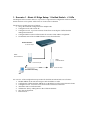
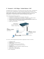
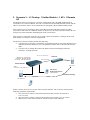
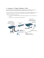
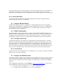
1. Scenario 1 - Basic L2 Edge Setup: 1 Unified Switch + 2 APs
The diagram in this scenario shows a very basic L2 edge network configuration with one Unified
Switch and two access points. All devices are in the same L2 domain.
The objectives in this setup are as follows:
• Set up the minimum configuration for multiple APs
• Configure an AP with a static IP
• Configure an ACL to prevent wireless clients from accessing the Unified Switch1
management interface.
• Configure DHCP on the Unified Switch for wireless client address assignment.
• Understand some of the D-LINK Wireless Access Point features.
Unified Switch1
10.90.90.90/8
SSID:
Guest Network
SSID:
Guest Network
AP1 10.90.90.91/8
AP2 10.90.90.92/8
Seamless Roaming
CL1
An overview of the configuration steps needed for Unified Switch and APs are as follows:
1. Disable DHCP on the APs and assign a static IP address to AP2.
2. Configure the Unified Switch1 DHCP server & address pool for Guest Network clients.
3. Configure an ACL to restrict access from clients on the Guest Network.
4. Attach the APs to Unified Switch1.
5. Validate the APs by adding them to the Valid AP database.
6. Save the configuration.
7. Perform tests.
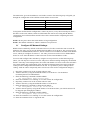
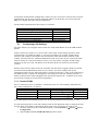
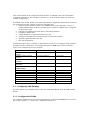
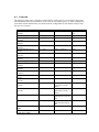
The table below gives the IP addresses used in this scenario. The following steps will guide you
through the configuration of the Unified Switch and the Access Point.
Device
Unified Switch
AP1
AP2
Client Address Pool
Subnet
10.90.90.90/8 (default)
10.90.90.91/8 (default)
10.90.90.92/8
10.90.91.1 – 10.90.91.254
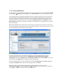
To begin the Unified Switch configuration, connect to port 12 (or any other unused port) from a
PC that is on the same subnet (10.0.0.0/8) and launch the web browser using this IP address,
10.90.90.90. The Unified Switches and the APs will be connected after completing the entire
configuration.
NOTE: Do not power down the switch before saving configuration.
NOTE: The default username is “admin” and there is no password.
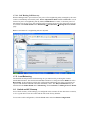
1.1
Configure AP Network Settings
DHCP client is enabled by default on the APs. However, for this scenario the APs use static IP
addresses. For AP1, you can use the default static IP address of 10.90.90.91, but you must access
the AP CLI to disable DHCP (otherwise, the AP would receive an address from the switch DHCP
server, which you configure in section 1.1. For AP2, you must access the CLI to disable DHCP
and to set a new static IP address so that it does not use the same IP address as AP1.
To access and configure AP1 and AP2 by using the access point CLI, use the following steps
(Note: you will only have CLI access to the APs prior to them becoming managed by the Unified
Switch. Once they reach managed state, the switch will disable CLI access to the APs such that a
user cannot modify the configuration of the AP while in managed mode since in this mode the
switch provides configuration information to the AP. It is possible to place a managed AP in
“debug” mode in order to temporarily allow CLI access to the AP for configuration changes.)
1. Physically connect a PC in the 10.0.0.0 subnet to AP1.
2. Telnet to the AP by using the default IP address of 10.90.90.91. Use the default
username/password of admin/admin.
3. Enter the following command to disable DHCP:
set management dhcp-status down
4. Enter the command “save-running” to save the current AP configuration.
5. Physically connect a PC in the 10.0.0.0 subnet to AP2.
6. Telnet to the AP by using the default IP address of 10.90.90.91.
7. Enter the following command to change the IP address:
set management static-ip 10.90.90.92
8. Telnet to the AP again by using the IP address of 10.90.90.92 since your initial session will
be dropped upon changing the address.
9. Enter the following command to disable DHCP:
set management dhcp-status down
10. Enter the command “save-running” to save the current AP configuration.
11. Enter the command “Exit” to logout the AP.
1.1. Configure the DHCP Server
The Unified Switch can function as a DHCP server to assign addresses to wireless (or wired)
clients that connect to each AP. To configure the DHCP Server, you must configure global
settings and the address pool for the clients.
For this scenario, wireless clients will be assigned addresses in the range of 10.90.91.1/8 –
10.90.91.254/8. By limiting the range of addresses, you can then configure an ACL to limit the
network access of all clients that have addresses within this range and still maintain additional
addresses in this space for static configuration for clients or servers.
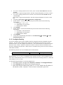
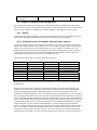
Since these addresses are on the 10.0.0.0 network as well as the AP and switch management
addresses, you must exclude all addresses that are not in the desired client range.
GuestPool
10.90.91.1 – 10.90.91.254
Excluded Addresses
10.0.0.1 - 10.90.91.0
10.90.92.0 – 10.255.255.255
Subnet Mask
255.0.0.0
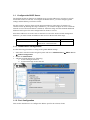
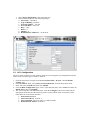
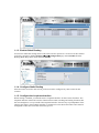
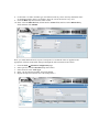
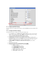
1.1.1. Global DHCP Configuration
Use the following procedures to configure the global DHCP settings.
1. Select the LAN tab from the navigation panel and access Administration Æ DHCP Server
Æ Global Configuration.
2. Enable the Admin Mode
3. Add the excluded addresses as following:
a. 10.0.0.0 through 10.90.91.0
b. 10.90.92.0 through 10.255.255.255
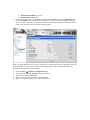
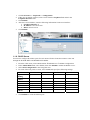
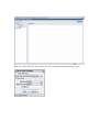
1.1.2. Pool Configuration
This section describes how to configure the address pool for the wireless clients.
1. Select Pool Configuration in the Navigation tree.
2. Select create and specify the following settings:
a. Pool Name – GuestPool
b. Type of Binding - Dynamic
c. Network Number – 10.0.0.0
d. Network Mask - 255.0.0.0
e. Days - 1 day
f. Hours - 0
g. Minutes - 0
h. Default Router Addresses – 10.90.90.90
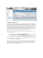
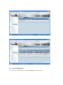
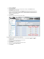
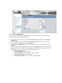
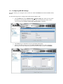
1.2. ACL Configuration
The ACL in this scenario prevents wireless clients from accessing the web management interface
of the switch. All other types of traffic is allowed.
1. From the LAN menu, navigate to the Access Control Lists > IP ACL > Access Profile
Settings page.
2. From the IP ACL field, select Create New Extended ACL from the drop-down menu.
3. Enter 100 in the ACL ID field, then click Submit.
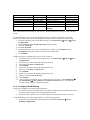
4. From the Rule Configuration page, enter 1 as the Rule ID, Deny as the Action, and False for
Match Every, then click Submit.
5. The screen refreshes with additional fields. Click the Configure button associated with the
appropriate fields and enter the following criteria to deny HTTP traffic from clients on the
Guest Network to the Switch and APs:
• Protocol Keyword: IP
• Source IP Address: 10.90.91.1
• Source IP Mask: 0.0.0.255 (This is a wildcard mask)
• Destination IP Address: 10.90.90.1
• Destination IP Mask: 0.0.0.255
• Destination L4 Port: http
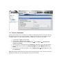
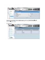
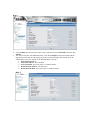
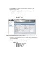
6. Create a new rule, enter 2 as the Rule ID, Permit as the Action, and True for Match Every,
then click Submit. The reason for this second rule is that an ACL has an implicit “deny all”
rule at the end. ACL rules are checked in order and the action of the first to match the flow is
taken. If no match occurs, the packet will be dropped.
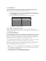
Rule 1
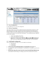
Next, you must attach the ACL to port 0/1 and port 0/13 (the physical ports to which the APs will
be connected) so that the rules are applied to the appropriate wireless client traffic that goes
through the APs connected to the switch.
1.
2.
3.
4.
5.
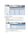
From the ACL Æ Interface Configuration page,
Select port 0/1 from the Slot/Port drop-down menu.
Select IP ACL as the ACL Type.
Enter 1 as the sequence number, and click Submit.
Repeat the steps to associate ACL 100 with port 0/13.
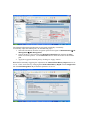
1.3. Wireless Configuration
You configure and monitor all wireless settings from the WLAN tab on the navigation panel.
Since the deployment is an L2 Edge and there are no subnet boundaries to cross, the switch can
use the network management IP address for the wireless functions (Note: the Unified Switch
component uses an IP address to manage the APs and peer-switches. In a L2 environment like
this scenario no inter-subnet routing is required. If however the scenario involves a L3
environment where wireless components including APs and peer-switches cross subnet
boundaries, a routing interface must be used, such as a loopback interface to allow routing of
control traffic between the Unified Switch and APs and peer switches.)
It is important to set the correct country code on the switch so that the APs operate in the
correct regulatory domain.
1. To configure wireless features, select the WLAN tab from the left pane and traverse
down the navigation tree to Administration Æ Basic Setup.
2. Select the Global tab in the right pane and make sure WLAN Switch Mode is enabled
3. Select the appropriate country code then click the Submit to submit the request.
Note: This scenario uses the default AP profile configuration, so you do not need to configure
any AAA/RADIUS, Radio, or SSID settings.
Note: The IP address on the Wireless Global Configuration page is the default management IP
address of the switch (10.90.90.90). This address is “chosen” by the system for use by the
Wireless component for communications with the APs and Peer Switches. If a loopback
interface is available, this will be selected first.
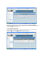
1.4. Device Connections
At this point, all the devices are ready to be connected. After the switch discovers the APs, they
will appear on the Failed list because the MAC addresses of the APs are not configured in the
Valid AP database (i.e. the switch has not been configured to accept any valid APs).
1. Connect AP1 to port 1 of the switch
2. Connect AP2 to port 13 of the switch
3. Wait about 60 seconds and click Monitoring Æ Access Points Æ Authentication
Failed Access Points.
4. Select the APs to be managed and click Manage to add them to the valid AP database.
5. To verify the status of APs, click Monitoring Æ Access Point Æ Managed Access
Points.
6. To view the local Valid AP database, click Administration Æ Basic Setup, then click
the Valid AP tab.
Note: The APs get into Failed Access Point list in about 60 seconds. After you select APs to be
managed, the APs enter to fully managed state in about 60 seconds.
1.5. Save Configuration
To save the switch configuration, select Save Changes from the tool bar.
1.6. Verify the Configuration
1.
2.
3.
4.
From a wireless client, verify that you can see the “Guest Network” SSID.
Using a wireless client, connect to the “Guest Network”.
Check the IP address that the switch DHCP server assigned.
Try pinging from a client on the Guest Network to the switch or AP IP address. The ping
should pass. Try web browsing to the switch IP address. The browse should fail because of
the ACL.
1.7. Feature Tests
This section has some recommend tests you can perform to demonstrate some of the Unified
Access System features. Note that the images in this section show IP address and other
configuration information that is different than the configuration used in Scenario 1. These
images are provide for reference and are not intended to be an exact match of what you see on
your switch.
1.7.1. L2 Start Roaming Test
Try roaming between the two APs (you can simulate this by disconnecting an AP from the switch
port that you are currently associated with assuming you are utilizing PoE to power the AP).
Check the associated client statistics to see which AP the client associates with and to observe
that the client has roamed to be associated with the other AP. If you start a Ping between the
client and the Unified Switch, you will also observe minimal packet loss during a roam.
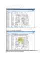
1.7.2. Auto channel adjustment after associating with AP2
To check the current operating channel and to see if any channel adjustment is required, select the
WLAN tab from the navigation panel and traverse down to Monitoring Æ Access Points Æ
Managed Access Points.
When an AP is powered up, the Initial Channel Selection (ICS) algorithm is used to select the
best operating channel. The algorithm scans all the available channels (based on the country code)
by counting the number of packets received on each channel and selects the channel with the
lowest packet count.
A second algorithm, Auto Channel Adjustment (ACA) is used to periodically evaluate the
operating channel. The radio must be configured for Auto Channel Adjustment. This can be done
by selecting the Automatic Channel check box in the Radio tab of the Basic Setup page. By
default this parameter is enabled.
Note: Any changes made to the profile configuration must be explicitly applied to the AP. To
apply the profile, navigate to Administration Æ Advanced Configuration Æ AP Profiles,
select the profile to apply, and click Apply. This will temporarily disable the radios as the new
configuration is applied to the access points that use the profile. In other words, you can make
and submit one or many changes to an AP profile however these configuration modifications will
not be applied to the AP until you manually apply the profile or an AP comes online into
managed state after the profile changes are submitted.
The Channel adjustment algorithm may be triggered periodically or manually.
To manually adjust the channel plan, use the following steps:
1. Select the WLAN tab from the navigation panel and navigate to Administration Æ AP
Management Æ RF Management.
2. Choose the 802.11 b/g and select the Manual Channel Plan tab and then the Start
button to start the process. Use the Refresh button to check the results of the channel
plan.
3. Apply the suggested channel plan by clicking on “Apply” button.
Note: Before manually triggering the adjustment, the Channel Plan History Depth must be set
to 0 or 1. This can be done by changing the Channel Plan History Depth in the Configuration
tab of the RF Management. By default this parameter is set to 5.
You may also manually change the operational channel from the Administration Æ AP
Management Æ Advanced page. Select the appropriate channel of the AP radio and change it to
the desired channel on the next screen.
1.7.3. Rogue AP Detection
To check the rogue AP list, select the WLAN tab from the navigation panel and navigate to
Monitoring Æ Access Points Æ Rogue/RF Scan Access Points.
1.7.4. Power Adjustment
To check power level, select the WLAN tab from the navigation panel and click Monitoring Æ
Access Points Æ Managed Access Points. Select Radio Details tab to check the power level.
The Automatic Power Adjustment algorithm works by setting the initial power of the AP to the
value specified in the AP profile. The power is then periodically adjusted to a level based on
presence or absence of packet transmission errors. The power is changed in increments of 10%.
Automatic adjustment can be done by selecting the Automatic Power in the Radio tab of the
Basic Setup. By default this parameter is enabled. The algorithm may be triggered by a periodic
timer or manually.
Note: The algorithm never reduces the AP power below the initial power setting as specified in
the profile and since the default power level in the default profile is 100 percent, the power would
never be reduced unless this value is first changed.
The power adjustment may be manually triggered by selecting the WLAN tab from the
navigation panel and traversing down to Administration Æ AP Management Æ RF
Management. Select the Manual Power Adjustments tab and then the Start button to start the
process (click the Apply button to apply new power adjustment)
You may change the power of the AP radio by selecting the Radio tab of the Basic Setup and
changing the Initial Power to the desired setting and click on submit.
Note: Any changes to the radio setting must be applied to the AP. To do this, click
Administration Æ Advanced Configuration Æ AP Profiles. Select the profile to apply, then
click Apply to update all APs that use the selected profile.
1.7.4.1. Self Healing Cell Recovery
When a Managed AP is powered down, the power of its neighboring AP(s) managed by the same
switch is immediately increased by 20%. Power Adjustment Mode should be Interval to see an
increase in power of neighboring AP. By default, Initial Power is 100%, so decrease power of
APs below 80% or less to see 20% increase before powering down one AP. The power level can
be verified in the Radio detail on the Monitoring ÆAccess Points Æ Managed Access Points
page.
Note: A maximum of 3 neighboring APs are adjusted.
1.7.5. Load Balancing
The Unified Switch performs load balancing on a per radio basis by tracking the wireless
bandwidth utilization. The maximum bandwidth utilization is configured in the Radio tab of the
Basic Setup. If the utilization reaches the configured threshold then new client associations are
rejected. The default bandwidth utilization threshold is 60%. The WLAN Utilization may be
monitored in the Radio Details tab of Monitoring Æ Access Points Æ Managed Access Points.
1.8. Switch and AP Cleanup
You will not need any of the settings you configured in this scenario for the other three scenarios,
so it is a good idea to reset the switch and the APs to the factory defaults.
To reset the switch configuration, click the Tools menu and select Reset Configuration.
To reset the AP configuration, you will need to telnet into the AP CLI and use the “factory-reset”
command. As mentioned earlier, you can place the AP into “debug” mode from the switch if the
AP is currently managed to gain access to the UI.
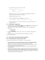
2. Scenario 2 – L2/L3 Edge: 1 Unified Switch + 2 AP
The diagram in this section shows a L2/L3 edge/overlay setup. In this scenario, a Unified Switch
acts as an L3 device. Although the two APs are directly connected to the switch, they are in
different subnets. Both the APs are managed by the D-LINK Unified Switch. Since the Unified
Switch supports VLAN routing, L2 paths can be established between the AP switch ports
although they are on different IP subnets such that L3 Tunneling is not required.
This scenario has the following objectives:
• Understand how to implement a real plug & play deployment.
• Configure VLAN routing interfaces to simulate a L3 network with multiple subnets.
• Create an ACL to block IP traffic between clients on different SSIDs.
• Assign IP addresses of APs & wireless clients through the Unified Switch DHCP server.
• Configure multiple SSIDs with different VLANs.
• Enable wireless encryption.
Unified Switch1
Network: 10.90.90.90/8
Loopback: 192.168.10.254
Port 0/1
VLAN 20
Port 0/13
VLAN 30
SSID:
D-LINK-NET1: VLAN 100
D-LINK-NET2: VLAN 200
Guest Network
SSID:
D-LINK-NET1: VLAN 100
D-LINK-NET2: VLAN 200
Guest Network
AP1 192.168.20.x
AP2 192.168.30.x
Seamless Roaming
CL1
An overview of the configuration steps needed to complete this scenario is as follows:
1.
2.
3.
4.
5.
6.
7.
8.
9.
10.
Configure VLANs
Configure VLAN routing interfaces
Enable routing
Create loopback interface for WLAN functions
Set up DHCP server and address pools for VLANs
Configure ACL
Configure the AP profile, including new SSIDs and security
Add VLANs to L2 discovery list
Attach, discover, and validate APs
Save configuration
To begin the Unified Switch configuration, connect to port 12 from a PC on the 10.0.0.0 network
and launch the web browser using the default IP address: 10.90.90.90/8. You connect the APs
after you complete the entire switch configuration.
The IP address information for this scenario is as follows:
Device
Unified Switch Management Interface
Unified Switch Loopback Interface
AP1
AP2
Wireless Clients on D-LINK-NET1
Wireless Clients on D-LINK-NET2
2.1
IP Address
10.90.90.0/8
192.168.10.254/32
192.168.20.x/24
192.168.30.x/24
192.168.100.x/24
192.168.200.x/24
Configuring LAN Settings
All of the features you configure in this section are within the LAN tab on the D-LINK Unified
Switch.
In this scenario, the switch is a L3 device with a total of four VLAN routing interfaces. Each
connected AP is in a different subnet, so you need to configure two separate VLAN routing
interfaces and configure an IP address for each interface. Each AP has three different VAPs
enabled, and each VAP uses a different SSID and VLAN. You create an ACL to block IP traffic
between clients on VAP1 and clients on VAP2, so you also need to configure VLAN routing
interfaces for the two VAPs. The third VAP is the Guest Network, which is not used in this
scenario.
When wireless clients connect to the AP, all traffic from the client is tagged with the VLAN ID
associated with the SSID that the client uses to connect. You must configure the VLAN
information on the switch so that client traffic is accepted on the ports. (Note: if the VLAN ID of
the SSID Network is equal to the untagged-VLAN configured on the AP, which by default is 1,
traffic on that Network will be untagged when injected into the network. A Radius server could
also be used to assign per-client VLAN assignments.)
1.1.1. Create VLANs
AP1 is connected to port 0/1, and AP2 is connected to port 0/13. The summary information for
the VLAN configuration is as follows:
VLAN ID
VLAN Name
Include Ports
IP Address
VLAN 20 (Interface 4/1)
AP1
Port 0/1 (Untag)
192.168.20.254
VLAN 30 (Interface 4/2)
AP2
Port 0/13 (Untag)
192.168.30.254
VLAN 100 (Interface 4/3)
D-LINK-NET1 Ports 0/1 and 0/13 (Tagged)
192.168.100.254
VLAN 200 (Interface 4/4)
D-LINK-NET2 Ports 0/1 and 0/13 (Tagged)
192.168.200.254
Also, the default VLAN (PVID) for port 0/1 is 20, and the default VLAN for port 0/13 is 30.
Use the following steps to create and configure each VLAN. Repeat the steps to configure all four
VLANs. Refer to the table for information about what value to configure for each VLAN.
1. From the LAN tab on the switch Web interface, click L2 Features Æ VLAN Æ VLAN
Configuration.
2. Select Create from VLAN ID and Name pull down menu.
3. Enter the VLAN ID.
4. Enter VLAN Name.
5. On the Slot/Port row for the port to include in the VLAN, select Include from the
Participation drop-down menu.
6. For VLAN 100 and VLAN 200, select Tagging from the drop-down menu for port 0/1
and 0/13. This configuration tells the switch to add an 802.1Q VLAN Tag to the packets
that egress the port on those VLANs. This is so that the AP knows which Network (or
SSID) to forward the traffic on.
7. Click Submit.
8. Repeat for each of the VLANs in the above table.
Configure the Port VLAN ID for ports 0/1 and 0/13.
1. From the LAN tab on the switch Web interface, click L2 Features Æ VLAN Æ Port
Configuration.
2. Select port 0/1 from the Slot/Port drop-down menu.
3. Enter 20 in the Port VLAN ID field.
4. Click Submit.
5. Select port 0/13 from the Slot/Port drop-down menu.
6. Enter 30 in the Port VLAN ID field.
7. Click Submit.
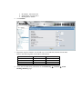
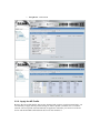
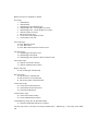
After you have repeated the steps to configure all four VLANs, use the Monitoring Æ VLAN
SummaryÆ VLAN Status and VLAN Port Status pages to verify that the VLANs and the
ports are configured properly.
VLAN Status
VLAN Port Status
1.1.2. Configure VLAN Routing
To configure the VLAN routing interfaces for AP1, AP2, and the two D-LINK-NET networks,
use the following steps.
1. Select the LAN tab from the navigation panel and click L3 Features Æ VLAN Routing
Configuration.
2. Enter the VLAN ID for VLAN 20 in the VLAN ID field and select Create to create a
VLAN routing interface for VLAN 20.
This creates a logical routing interface with the slot/port designation of 4/1 for VLAN 20.
3. Repeat the previous step to create the VLAN routing interfaces for VLAN 30, 100, and
200 (shown below).
4. Navigate to L3 Features Æ IP Æ Interface Configuration.
5. Select interface 4/1 from the Slot/Port drop-down menu and enter the following
information:
a. IP Address: 192.168.20.254
b. Subnet Mask: 255.255.255.0
c. Routing Mode: Enable
6. Click Submit.
7. Repeat the steps for interface 4/2 (VLAN 30), 4/3 (VLAN 100), and 4/4 (VLAN 200).
Refer to the following table for IP address information:
Interface
Interface 4/1
Interface 4/2
Interface 4/3
Interface 4/4
IP Address
192.168.20.254
192.168.30.254
192.168.100.254
192.168.200.254
Subnet Mask
255.255.255.0
255.255.255.0
255.255.255.0
255.255.255.0
8. Verify the VLAN Routing information on the Monitoring Æ L3 Status Æ VLAN
Routing Summary page.
1.1.3. Enable Global Routing
You need to enable the routing mode to allow the switch to operate as a L3 device in this scenario.
To do this, navigate to the L3 Features Æ IP Æ Configuration page. Select Enable from the
Routing Mode drop-down menu and click Submit.
1.1.4. Configure Static Routing
Since all routes are local to the switch, you do not need to configure any static routes for this
scenario.
1.1.5. Configure the Loopback Interface
When routing is enabled, you should create a Loopback interface for the wireless functions. The
loopback interface isolates the wireless functions from other switching and routing functions that
the switch might use. A key benefit to the loopback interface is that it stays up independent of the
physical port status. The loopback interface is created on its own subnet and static routes must be
configured to allow the rest of the network to get to it.
1. Click L3 Features -> Loopbacks -> Configuration
2. If they are not already selected, select Create from the Loopback field and 0 in the
Loopback Interface field.
3. Click Submit.
4. After the screen refreshes, enter the following information for the new interface:
a. Loopback Interface: 0
b. IP Address: 192.168.10.254
c. Mask: 255.255.255.0
5. Click Submit.
1.1.6. DHCP Server
You need to configure IP address pools for each AP and for the clients that connect to the APs
through the D-LINK NET1 and DLINK-NET2 SSIDs.
1.
2.
3.
4.
From the LAN menu, click Administration Æ DHCP Server Æ Global Configuration
In the Admin Mode field, select Enable, then click Submit to enable the DHCP server..
Select Pool Configuration in the Navigation tree.
For each of the four pools to create, select create and specify the following settings:
Pool Name
Type of
Binding
Network
Number
Network Mask
Days
Hours
Minutes
Default Router
Address
AP1
Dynamic
AP2
Dynamic
VLAN 100
Dynamic
VLAN 200
Dynamic
192.168.20.0
192.168.30.0
192.168.100.0
192.168.200.0
255.255.255.0
1 day
0
0
192.168.20.254
255.255.255.0
1 day
0
0
192.168.30.254
255.255.255.0
1 day
0
0
192.168.100.254
255.255.255.0
1 day
0
0
192.168.200.254
5. Click Submit to create the address pool.
1.1.7. ACL Configuration
The ACL in this scenario blocks IP traffic between wireless clients who access the network
through D-LINK-NET1 and D-LINK-NET2.
1. From the LAN menu, navigate to the Access Control Lists > IP ACL > Access Profile
Settings page.
2. From the IP ACL field, select Create New Extended ACL from the drop-down menu.
3. Enter 100 in the ACL ID field, then click Submit.
4. From the Rule Configuration page, enter 1 as the Rule ID, Deny as the Action, and click
Submit.
5. The screen refreshes with additional fields. Click the Configure button associated with the
appropriate fields and enter the following criteria to deny IP traffic from clients on the DLINK-NET1 network to clients on the D-LINK-NET2 network:
• Protocol Keyword: IP
• Source IP Address: 192.168.100.0
• Source IP Mask: 0.0.0.255 (This is a wildcard mask)
• Destination IP Address: 192.168.200.0
• Destination IP Mask: 0.0.0.255 (This is a wildcard mask)
Rule 1
6. From the Rule drop-down menu, select Create, and enter 2 into the Rule ID field, then click
Submit.
7. The screen refreshes with additional fields. Click the Configure button associated with the
appropriate fields and enter the following criteria to deny IP traffic from clients on the DLINK-NET2 network to clients on the D-LINK-NET1 network:
• Protocol Keyword: IP
• Source IP Address: 192.168.200.0
• Source IP Mask: 0.0.0.255 (This is a wildcard mask)
• Destination IP Address: 192.168.100.0
• Destination IP Mask: 0.0.0.255 (This is a wildcard mask)
Rule 2
8. Create Rule 3 to allow all other type of traffic between any source and any destination since
as mentioned earlier, there is an implicit “deny all” rule at the end of every ACL.
9. From the Rule drop-down menu, select Create.
10. Enter 3 into the Rule ID field, Permit into the Action field, and True in the Match Every
field, and then click Submit.
Next, you must attach the ACL to port 0/1 and port 0/13 so that the rules are applied to the
appropriate wireless client traffic that goes through the APs connected to the switch.
1.
2.
3.
4.
5.
From the ACL Æ Interface Configuration page,
Select port 0/1 from the Slot/Port drop-down menu.
Select IP ACL as the ACL Type.
Enter 1 as the sequence number, and click Submit.
Repeat the steps to associate ACL 100 with port 0/13.
1.2. Configuring WLAN Settings
All of the features you configure in this section are within the WLAN tab on the D-LINK Unified
Switch.
Use the following steps to configure the Unified Switch and the APs.
1. On the Global tab of the Administration Æ Basic Setup page, make sure the switch
IP address is the Loopback interface address (192.168.10.254), the country code is
correct, and that the WLAN Switch Operational Status is Enabled.
2. Click Next to go to the Discovery tab on the Basic Setup page.
3. Add VLAN 20 and VLAN 30 to the L2/VLAN Discovery list (to allow automatic
discovery of the APs connected to ports on VLANs 20 and 30), then click Submit.
4. Click the SSID tab to configure the VAP and Network settings for the APs.
5. Select the 802.11b/g radio.
6. Select the check box next to Managed SSID 2 and click Edit.
7. Change the following Network parameters and select Submit:
a. SSID – D-LINK-NET1
b. VLAN – 100
c. Security – WEP
•
•
•
•
Authentication – Open System
WEP Key Type – ASCII
WEP Key Length – 64
WEP Key 1 – 98765
Note: For convenience, the SSID created under one radio is propagated to the second radio. The
SSID parameters on the second radio may then be modified.
8. To repeat the procedure and add a second secure network, return to the SSID page by
clicking on the SSID tab.
9. Select the check box next to Managed SSID 3 and click Edit.
10. Change the following parameters and select Submit:
a. SSID – D-LINK-NET2
b. VLAN – 200
c. Security – WEP
• Authentication – Open System
• WEP Key Type – ASCII
• WEP Key Length – 64
• WEP Key 1 – 98765
1.3. Save Configuration
Use the Tool menu to save the switch configuration.
1.4. Device Connections
This section outlines the connections needed between the Unified Switches and the APs. At this
point, all the devices are ready to be connected. After the switch discovers the APs, they will
become managed since the MAC addresses of the APs were added to the Valid AP database in
Scenario 1 (unless you reset the configuration between scenarios in which case you would have to
re-add the MAC addresses of the APs to the local database). The updated AP profile is applied to
the APs upon validation
1. Connect AP1 to port 1 of the switch
2. Connect AP2 to port 13 of the switch
3. Wait about 60 seconds and click Monitoring Æ Access Points Æ Managed Access
Points (Note: you might find the APs in the Authentication Failed Access Points
page if you have not added the MAC addresses of the APs to your local database).
1.5. Verifying the Configuration
From a wireless client, verify that you can see the SSIDs for the following:
• Guest Network
• D-LINK NET1
• D-LINK NET2
1. Connect to one of the D-LINK-NET SSIDs to verify that WEP security is enforced.
2. After connecting, check the IP address that the switch DHCP server assigned.
3. Try pinging from a client on D-LINK-NET1 to D-LINK-NET2. The ping should fail because
of the ACL.
4. Perform a “fast roam” from one AP to the other on one of the D-LINK-NET SSIDs (this can
be simulated by pulling power on the AP you are currently associated with) and observe that
your IP address does not change even though you have now associated with an AP on a
different subnet. Fast roams will not function on the Guest Network SSID because the client
will be forced to acquire a new IP address.
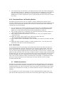
3. Scenario 3 – L3 Overlay: 1 Unified Switch + 1 AP + 1 Remote
AP
The diagram in this section shows a network configuration with a D-LINK Unified Switch
connected to an L3 Device/Router. One AP is connected to the D-LINK Unified Switch, and the
other is connected to the L3 device. Both APs are managed by the D-LINK Unified Switch.
This scenario uses L3 tunneling so that a client that associated with AP1 initiates an audio
conversation and roams to a different subnet. In the process, the client is disassociated with AP1
and gets associated with AP2 maintaining the audio conversation.
This scenario is especially useful for you to setup a demo in customers’ existing network with
little change to customers’ network configuration.
The objectives for this scenario include the following:
• To know how to setup the L3 tunneling (L3 Tunneling must be used since the APs are on
different IP subnets and there is not a L2 path between the APs for the WLAN Network
data).
• To know how to manage the remote AP and the most practical deployment into
customers’ existing networks.
Across L3 Network
Network IP: 10.90.90.90
Loopback: 192.168.10.254
L3 Tunnel: 192.168.250.254
L3 Device
172.17.5.0/24
172.17.6.0/24
Unified Switch1
AP2
172.17.6.x
SSID:
L3-Tunnel: 192.168.250.x
FTP Server
Audio/Video Server
192.168.250.x
Seamless Roaming
AP1
192.168.20.x
CL1
In this scenario, the L3 device is part of the customer network. The L3 device must meet the
following minimum requirements:
• One network to connect to the Unified Switch (in this scenario, the network is
172.17.5.0/24)
• One network to connect to AP2 (in this scenario, the network is 172.17.6.0/24)
• DHCP server in the AP2 network for AP and wireless client addresses
This scenario builds on the configuration from Scenario 2. Although some of the information
configured in Scenario 2 does not apply to Scenario 3, you do not need to delete any of the preexisting configurations.
In addition to the VLAN, DHCP, ACL and Unified Switch configuration performed in Scenario 2,
the configuration for this scenario involves the following steps:
1. Assign a static IP address to AP2 or use a DHCP server on the customer L3 device or
configure DHCP Relay on the L3 customer device to point to a DHCP Server configured
on the unified switch.
2. Configure two additional VLANs and VLAN routing interfaces.
3. Configure a default route.
4. Add the IP address of AP2 to the L3 discovery list.
5. Configure and enable the L3 Tunnel network on the Unified Switch.
6. Apply the updated profile to the APs.
7. Save the configuration.
The following table shows a summary of the interfaces or devices you configure, along with their
IP address and port information. You configure the entries in bold in this scenario. All other
entries were configured in previous scenarios.
Interface/Device
Unified Switch Management
Interface
Unified Switch Loopback
Interface
Unified Switch L3 Tunnel
Interface
Unified Switch Interface to
L3 Device
L3 Device Interface to
Unified Switch
FTP Server
Audio/Video Server
AP1
AP2
Clients on D-LINK-NET1
Clients on D-LINK-NET2
Clients on L-3 Tunnel
IP Address
10.90.90.90/8
Port
Any unused
192.168.10.254/32
Logical only
192.168.250.254/24
Logical only
172.17.5.253/24
0/24
172.17.5.254/24
L3 device port
192.168.250.x/24
192.168.250.x/24
192.168.20.x/24
172.17.6.1/24
192.168.100.x/24
192.168.200.x/24
192.168.250.x/24
0/21
0/22
0/1
L3 device port
Wireless
Wireless
Wireless
3.1. Configuring LAN Settings
All of the features you configure in this section are within the LAN tab on the D-LINK Unified
Switch.
3.1.1. Configure the VLANs
The summary information for the VLAN configuration is as follows (the bold entries are new for
this scenario, and the grey entries were configured in Scenario 2):
VLAN ID
VLAN 20 (Interface 4/1)
VLAN 30 (Interface 4/2)
VLAN 100 (Interface 4/3)
VLAN 200 (Interface 4/4)
VLAN 5 (Interface 4/5)
VLAN 250 (Interface 4/6)
VLAN Name
AP1
AP2
D-LINK-NET1
D-LINK-NET2
Customer-NET
L3-Tunnel-NET
Include Ports
Port 0/1
Port 0/13
Ports 0/1 and 0/13
Ports 0/1 and 0/13
Port 0/24 (Untag)
Ports 0/21 and 0/22
(Untag)
IP Address
192.168.20.254
192.168.30.254
192.168.100.254
192.168.200.254
172.17.5.253
192.168.250.254
Also, the default VLAN (PVID) for port 0/24 is 5, and the default VLAN for ports 0/21 and 0/22
is 250.
Use the following steps to create and configure VLAN 5, and then repeat them to configure
VLAN 250. Refer to the table for information about what value to configure for each VLAN.
1. From the LAN tab on the switch Web interface, click L2 Features Æ VLAN Æ VLAN
Configuration.
2. Select Create from VLAN ID and Name pull down menu.
3. Enter the VLAN ID.
4. Enter VLAN Name.
5. On the Slot/Port row for the port to include in the VLAN, select Include from the
Participation drop-down menu for the ports listed in the table.
6. Click Submit.
Configure the Port VLAN ID for ports 0/21, 0/22, and 0/24.
1. From the LAN tab on the switch Web interface, click L2 Features Æ VLAN Æ Port
Configuration.
2. Select port 0/21 from the Slot/Port drop-down menu.
3. Enter 250 in the Port VLAN ID field.
4. Click Submit.
5. Select port 0/22 from the Slot/Port drop-down menu.
6. Enter 250 in the Port VLAN ID field.
7. Click Submit.
8. Select port 0/24 from the Slot/Port drop-down menu.
9. Enter 5 in the Port VLAN ID field.
10. Click Submit.
11. After you have repeated the steps to configure all four VLANs, use the Monitoring Æ
VLAN SummaryÆ VLAN Status and VLAN Port Status pages to verify that the
VLANs and the ports are configured properly.
3.1.2. Configure VLAN Routing
You need to configure two VLAN routing interfaces:
• An interface for the FTP/Audio/Video server that is attached to the L3 Tunnel subnet and
is used for WLAN clients on the Tunneled SSID Network.
• An interface that connects to the customer network (simulated here by the L3 device).
To configure the new VLAN routing interfaces, use the following steps.
1. Select the LAN tab from the navigation panel and click L3 Features Æ VLAN
Routing Configuration.
2.
3.
4.
5.
6.
7.
8.
9.
To create a routing interface for VLAN 5, enter 5 into the VLAN ID field and select
Create.
This creates a logical routing interface with the slot/port designation of 4/5 for VLAN 5.
To create a routing interface for VLAN 250, enter 250 into the VLAN ID field and
select Create.
This creates a logical routing interface with the slot/port designation of 4/6 for VLAN
250.
Navigate to L3 Features Æ IP Æ Interface Configuration.
Select interface 4/5 from the Slot/Port drop-down menu and enter the following
information:
a. IP Address: 172.17.5.253
b. Subnet Mask: 255.255.255.0
c. Routing Mode: Enable
Click Submit.
Select interface 4/6 from the Slot/Port drop-down menu and enter the following
information:
d. IP Address: 192.168.250.254
e. Subnet Mask: 255.255.255.0
f. Routing Mode: Enable
Click Submit.
Verify the VLAN Routing information on the Monitoring Æ L3 Status Æ VLAN
Routing Summary page.
3.1.3. Configure Routing
You must configure routes on the Unified Switch for integration with the simulated customer
network. You can either configure static routes for each network you need access to at the
Unified Switch or you can configure a default route. The Unified Switch at a minimum requires
IP access to the “remote” AP that is connected via the L3 router to allow the Unified Access
System to manage that remote AP. Other routes (or a default route) provide access for clients to
reach other networks.
The following default route can be added on the Unified Switch.
Customer Network Address
0.0.0.0
Mask
0.0.0.0
Next Hop IP Address
172.17.5.254
Note: Interface 172.17.5.254 is a counterpart router interface on the L3 device attached to port
0/24 on the Unified Switch. Port 0/24 is associated with the VLAN routing interface 5, which has
an IP address of 172.17.5.253.
Use the following procedures to create the default route.
1. From the LAN tab, navigate to L3 Features Æ Router Æ Configured Routes.
2. Select Default from the Route Types drop-down menu.
3. In the Next Hop IP Address field, enter 172.17.5.254, which is the IP address of
the interface on the “customer” L3 device that is connected to port 0/24.
Proper static routes to Unified Switch must be also configured on the “customer” L3 device as
well. In a customer environment, you would need to configure the following static routes on the
customer’s L3 device.
Network Address
192.168.10.0
Mask
255.255.255.0
Next Hop IP Address
172.17.5.253
Note: The above static route provides an IP path back to the loopback interface on the Unified
Switch for the remote AP to access to become managed by the Unified Access System. Without
additional routes, wired clients on the customer’s L3 device will not be able to reach other
subnets on the Unified Switch. This includes connectivity between wireless clients on AP1 and
AP2 if they associate with a non-Tunneled SSID.
##################################################################
Setting Example
Settings for L3 Switch:
V5 (Connect to Unified Switch)
#config
#create
#config
#create
vlan
vlan
vlan
ipif
default delete 1-16
v5 tag 5
v5 add untagged 1-8
net2 172.17.5.254/24 v5
V6 (Connect to AP2)
#create vlan v6 tag 6
#config vlan v6 add untagged 9-16
#create ipif net3 172.17.6.254/24 v6
Set static route
#create iproute 192.168.10.0/24 172.17.5.253
Enable Jumbo Frame (Set MAX MTU size for all port)
#enable jumbo_frame
#save
Settings for AP2 via Telnet:
#set management dhcp-status down
#set management static-ip 172.17.6.1
(Telnet again with new IP)
#set management static-mask 255.255.255.0
#set static-ip-route gateway 172.17.6.254
#save-running
3.1.4. DHCP Server
You need to configure a new IP address pool for the clients that connect to the L3 Tunnel
network (the FTP/Audio/Video server and the wireless clients that connect to the L3 Tunnel
SSID). The DHCP server should already be enabled from Scenario 2.
1.
2.
3.
4.
5.
From the LAN menu, click Administration Æ DHCP Server Æ Global Configuration
In the Admin Mode field, select Enable, then click Submit to enable the DHCP server..
Select Pool Configuration in the Navigation tree.
For the new address pool, select create and specify the following settings:
Pool Name
Type of Binding
Network Number
Tunnel
Dynamic
192.168.250.0
Network Mask
Days
Hours
Minutes
Default Router Address
255.255.255.0
1 day
0
0
192.168.250.254
Click Submit to create the address pool.
3.1.4.1. DHCP on the Customer Network
For this scenario, AP2 resides in the “customer” network. Configure the L3 device in the
customer network to assign the IP address 172.17.6.1 to AP2. You will use this IP address to add
to the L3/IP discovery list.
3.1.5. Setting the MTU Size
The MTU determines the maximum size of a packet that can be transmitted through a port in one
frame. The default MTU size for the ports on the D- Link Unified Switch is 1518 bytes. Packets
that use the L3 tunnel have an extra 20 bytes in the header for encapsulation. To support these
larger frames, you can increase the MTU size on all intermediate ports and unified switch ports.
The AP can transmit and receive frames of up to 1542 bytes on the LAN port
If you use tunneling only for IP telephony, or if you set the MTU size on all wireless clients that
use tunneling to 1480, you do not need to increase the MTU size in the network.
The following example shows how to change the MTU size on port 0/1 to 1542 bytes. You will
need to repeat the steps for port 0/24. Also, make sure the port on the “customer” L3 device
where AP2 is attached has an MTU size of at least 1542.
1. From the LAN tab, access the Administration > Port Configuration > Port Configuration
page.
2. From the Slot/Port or Unit/Slot/Port field, select the port to configure from the drop-down
list, or select All to configure all ports.
3. Enter 1542 as the MTU size in the Maximum Frame Size field.
4. Click Submit to apply your changes to the running configuration.
3.2. Configuring WLAN Settings
All of the features you configure in this section are within the WLAN tab on the D-LINK Unified
Switch.
3.2.1. Configure the Basic Settings
Use the following steps to configure the Unified Switch and the APs.
1. On the Global tab of the Administration Æ Basic Setup page, make sure the switch IP
address is the Loopback interface address (192.168.10.254), the country code is correct,
and that the WLAN Switch Operational Status is Enabled.
2. Click Next to go to the Discovery tab on the Basic Setup page.
3. Add the IP address for AP2 (172.17.6.1, which is on the “customer” network) to the
L3/IP Discovery list, and then click Submit (Note: since you do not know for sure which
IP address the DHCP Server on the “customer” network will provide to AP2, you can
configure a range of IP addresses to add to the L3 Discovery list).
4. Click the SSID tab to configure the VAP and Network settings for the L3-Tunnel
network..
5. Select the 802.11b/g radio.
6. Select the check box next to Managed SSID 4 and click Edit.
7. Change the following Network parameters and select Submit:
b. SSID – L3-Tunnel
c. L3 Tunnel Check Box: Enabled
d. L3 Tunnel Subnet: 192.168.250.0
e. L3 Tunnel Mask: 255.255.255.0
f. Security: WPA/WPA2 – WPA Personal
g. WPA Versions: WPA & WPA2
h. WPA Ciphers: TKIP & CCMP
i.
Passphrase: 1234567890
3.2.2. Apply the AP Profile
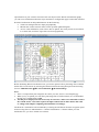
Because the AP profile that the APs use has changed and you have not disconnected AP1, you
can manually re-apply the AP profile settings in order to update it with the new L3-Tunnel
network. The new profile will automatically be applied to AP2 after you connect it to the L3
device and the D-LINK Unified Switch discovers and validates it.
1. To apply the updated AP profile, access the Administration Æ Advanced
Configuration Æ AP Profiles page under the WLAN tab.
2. Select the check box next to Profile1 – Default.
3. Click Apply to apply the new profile to AP1.
3.3. Save Configuration
Save the switch configuration.
3.4. Device Connections
This section outlines the connections needed between the Unified Switches and the APs. At this
point, all the devices are ready to be connected. After the switch discovers the APs, they will
become managed since the MAC addresses of the APs were added to the Valid AP database in
Scenario 1.
1.
2.
3.
4.
5.
Make sure AP1 is connected to port 1 of the switch
Connect port 0/24 to a port on the “customer” L3 device in the 172.17.5.0 network.
Connect ports 0/22 and 0/21 to the FTP/Audio/Video devices.
Connect AP2 to a port in the 172.168.6.0 network on the “customer” L3 device.
Wait about 60 seconds and click Monitoring Æ Access Points Æ Managed Access
Points to make sure that both APs are managed by the switch.
3.5. Verifying the Configuration
1.
2.
3.
4.
5.
Make sure that the L3 Tunnel Status is “Configured” for the L3-Tunnel network (on
the Wireless Network Configuration page of the L3-Tunnel network
Administration Æ Basic Setup Æ SSID
From a wireless client, verify that you can see the SSIDs for the following:
• Guest Network
• D-LINK NET1
• D-LINK NET2
• L3-Tunnel
Connect to the L3-Tunnel SSID with WPA2-PSK security configured on the client.
After connecting, check the IP address that the switch DHCP server assigned.
Start the Roaming Test.
3.6. Testing the L3 Roaming Feature
3.6.1. Simulated Roam via Power Down of AP
The following procedure shows how to perform an L3 Tunnel roaming test.
1. Use your laptop to test wireless connection by associating to the “L3-Tunnel” SSID Network,
and check if you’re getting the IP address correctly from the Unified Switch’s DHCP server
on the Tunnel subnet.
2. Once wireless connectivity is confirmed, you can check which AP your laptop connects to
[ WLAN/ Monitoring/ Client/ Associated Clients ].
3. Start to Ping one of the LAN interfaces (172.17.5.253 or .254) or its loopback interface
( 192.168.10.254 ).
4. Disconnect the AP which your laptop is associated with and see how soon you can roam to
the other AP. Normally 1 ping loss is observed when roaming. (Note: Please see section
3.6.1 below for an alternative mechanism for simulating a roam)
5. You can repeat step 2-4 and observe your laptop roam from AP to AP without changing IP,
and with limited packet loss.
Note: You will not be able to seamlessly roam between AP1 and AP2 using the other SSIDs
since these are not configured for L3 Tunneling and these APs are on different IP subnets which
will require the client to obtain a new IP address on a non tunneled SSID.
3.6.2. Simulated Roam via Disabling Radios
The following procedure shows how to simulate a roam by disabling the radio the client is
currently associated with. By using this method, the link between the AP and the Unified Switch
will not go down and therefore the local route will not be removed and the above mentioned
routing loop issue will not happen.
1. Use your laptop to test wireless connection by associating to the “L3-Tunnel” SSID Network,
and check if you’re getting the IP address correctly from the Unified Switch’s DHCP server
on the Tunnel subnet.
2. Once wireless connectivity is confirmed, you can check which AP your laptop connects to
[ WLAN/ Monitoring/ Client/ Associated Clients ].
3. Start to Ping one of the LAN interfaces (172.17.5.253 or .254) or its loopback interface
( 192.168.10.254 ).
4. Enable AP “debug” mode to allow direct Telnet access to the APs CLI
[ WLAN/Administration/AP Management/Advanced ].
5. Open a Telnet session to the IP address of the AP which your client has associated with and
login.
6. Disable the radios with this command: “set radio all status down”. You will observe the
client roam to the other AP with minimal ping loss.
3.6.3. Real Roam
A real-world roam involves physically moving from near one AP to the other such that your
client will automatically associate with the closer AP of stronger signal strength. This is best
shown when the APs are adequately separated to allow signal strength decrease as you move
away one AP and signal strength increase from the other AP as you move nearer. Wireless VoIP
phones are the best clients to use since they are tuned to roam if a stronger signal is detected from
another nearby AP. PC clients are not tuned for these rapid roams and therefore will often allow
the signal strength to decrease significantly before selecting a stronger signal AP to associate
with – this can cause traffic loss simply associated with a weak signal. To facilitate the client’s
decision to roam an antenna can be connected to one of the APs after you have already associated
with the other.
3.7. Logs & Traps
The administrator can enable or disable SNMP traps sent from the Unified Switch and the trap
destinations. The traps can be enabled or disabled by traversing to Administration Æ Advanced
Configuration Æ Global in the WLAN tab. In managed mode the AP doesn’t generate any
traps. The list below shows all the possible traps generated on the Unified Switch:
Note: All traps are disabled by default.
WS Traps
1. WS Enabled
2. WS Disabled
3. WS Managed AP Database Full
4. WS Managed AP – AP Neighbor List Full
5. WS Managed AP – Client Neighbor List Full
6. WS-AP Failure List Full
7. RF Scan AP List Full
8. Client Association Database Full
9. Client Failure List Full
Peer WS Traps
10. Peer WS Discovered
11. Peer WS Failed
12. Peer WS Unknown Protocol Discovered
AP State Traps
13. WS Managed AP Discovered
14. WS Managed AP Failed
15. WS Managed AP Unknown Protocol Discovered
AP Failure Traps
16. WS-AP Association Failure
17. WS-AP Authentication Failure
Rogue AP Traps
18. RF Scan Rogue AP Detected
RF Scan Traps
19. RF Scan New AP Detected
20. RF Scan New Client Detected
21. RF Scan Ad-Hoc Client Detected.
Client State Traps
22. Client Association Detected
23. Client Disassociation Detected
24. Client Roam Detected
Client Failure Traps
25. Client Association Failure
26. Client Authentication Failure
Load Balancing Traps Per AP Per Radio Basis
27. Wireless bandwidth utilization exceeded
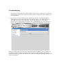
The trap logs can be viewed by traversing to DWS-3024 -> Monitoring -> Trap Logs in the LAN
tab.
3.8. Syslog Configuration
Enable Syslog by traversing to DWS-3026 -> Administration -> System Log Configuration and
selecting submit. Then, configure syslog server by providing the server IP Address and selecting
the level of Severity Filter and selecting submit.
3.9.
Debug
This section outlines information required for engineering debugging. Connect your laptop/PC to
Unified Switch’s serial console or telnet to the IP address of the switch and capture the following
information:
1. show running-config
2. show logging traplogs
3. show logging buffered
4. Scenario 4 – L3 Edge: 2 Switches + 2 APs
This scenario involves a larger Unified Switch managed network, which consists of multiple
Unified Switches (in this example there are two) connected over a L3 core network.
Also, in this scenario, the L3-Tunnel network is updated to require WPA2 authentication for “fast
authenticated roaming.” The security is WPA Enterprise, which requires a RADIUS server.
Scenario 4 has the following objectives:
• To know how to setup the multiple Unified Switch deployment as peer switches across a
L3 core.
• To know how to setup WPA2-EAP Authentication
Unified Switch2
Network IP: 10.90.90.91
Loopback: 192.168.20.250
L3 Tunnels: 192.168.2.253
192.168.3.253
192.168.100.253
Unified Switch1
Network IP: 10.90.90.90
Loopback: 192.168.10.250
L3 Tunnels: 192.168.2.254
192.168.3.254
192.168.100.254
Across L3 Network
L3 Device
172.17.6.0/24
AP2
172.17.5.0/24
192.168.102.x/24
RADIUS Server
192.168.4.0/24
FTP Server
Audio/Video Server
192.168.5.x/24
AP1
192.168.101.x/24
Client
Seamless Roaming
SSIDs:
Guest: 192.168.100.x/24
D-LINK-NET1: 192.168.2.x/24
D-LINK-NET2: 192.168.3.x/24
4.1. Overview
The following tables show a summary of the interfaces on the devices you configure, along with
their IP address and port information as well as the VLANs, DHCP pools, etc. This configuration
starts from scratch and therefore you should clear the configuration on the unified switches from
the previous scenarios.
Interface/Device
Switch1 Management
Interface
Switch1 Loopback Interface
Switch1 L3 Tunnel
Interface
Switch1 L3 Tunnel
Interface
Switch1 L3 Tunnel
Interface
Switch1 Interface to L3
Device
L3 Device Interface to
Switch1
Switch2 Management
Interface
Switch2 Loopback Interface
Switch2 L3 Tunnel
Interface
Switch2 L3 Tunnel
Interface
Switch2 L3 Tunnel
Interface
Switch2 Interface to L3
Device
L3 Device Interface to
Switch2
FTP or other Server on
Switch1
VLAN ID/Name
NA
IP Address
10.90.90.90/8
NA
2 - RD
192.168.10.250/32
192.168.2.254/24
Port
Any unused L2
port
Logical only
Logical only
3 - Sales
192.168.3.254/24
Logical only
100 - Guest
192.168.100.254/24
Logical only
10 - Core
172.17.5.253/24
0/24
NA
172.17.5.254/24
L3 device port
NA
10.90.90.91/24
Any unused
NA
2 - RD
192.168.20.250/32
192.168.2.253/24
Logical only
Logical only
3 - Sales
192.168.3.253/24
Logical only
100 - Guest
192.168.100.253/24
Logical only
10 - Core
172.17.6.253/24
0/24
NA
172.17.6.254/24
L3 device port
5 - Server
0/13
Wireless
RADIUS Server on
Switch2
4 - Server
AP1 on Switch1
101 – AP1
AP2 on Switch2
102 – AP2
DHCP for Clients on Guest
SSID
DHCP for Clients on DLINK-NET1 SSID
NA
192.168.5.254/24
192.168.5.x/24 for
server
192.168.4.254/24
192.168.4.x/24 for
server
192.168.101.254/24
192.168.101.x/24 for
AP
192.168.102.254/24
192.168.102.x/24 for
AP
192.168.100.x/24
NA
192.168.2.x/24
0/13
0/1
0/1
Wireless
DHCP Clients on D-LINKNET2 SSID
NA
192.168.3.x/24
Wireless
4.2. Switch1 & Switch2 LAN Configuration
The configuration in this section takes place on Unified Switch1 and Unified Switch2, and all
features are under the LAN tab on the navigation panel. Please follow the steps you have learned
from previous scenarios to configure the VLANs, interfaces, and addresses on the systems.
4.2.1. DHCP
Configure DHCP Server parameters and pools on Unified Switch1 to provide addresses for AP1,
Guest, Sales, and RD Tunneled WLAN Clients and for AP2 on Unified Switch2.
4.2.2. Configure routes on Switch1, Switch2, and L3 device
You must configure routes on the Unified Switch and L3 core device to provide IP connectivity
between the Unified Switches, APs, and servers. You can either configure static routes for each
network you need access to at the Unified Switch or you can configure a default route. The
Unified Switch at a minimum requires IP access to the other Unified Switch to allow peering to
occur and the APs must have IP access to the RADIUS server for WPA2. Other routes (or a
default route) provide access for clients to reach other networks.
The following default and static routes should be configured.
Device
Unified Switch1
Unified Switch2
L3 Device
L3 Device
L3 Device
L3 Device
L3 Device
L3 Device
Network Address
0.0.0.0
0.0.0.0
192.168.101.0
192.168.102.0
192.168.4.0
192.168.10.0
192.168.20.0
192.168.5.0
Mask
0.0.0.0
0.0.0.0
255.255.255.0
255.255.255.0
255.255.255.0
255.255.255.0
255.255.255.0
255.255.255.0
Next Hop IP Address
172.17.5.254
172.17.6.254
172.17.5.253
172.17.6.253
172.17.6.253
172.17.5.253
172.17.6.253
172.17.5.253
Note: The static route toward AP1, AP2, and the Radius server is needed only for WPA2-EAP
authentication.
Note: A default route above will direct all unknown IP traffic from the Unified Switch to the
“customer” L3 switch and configured a route on the L3 switch to direct traffic to the Unified
Switch to reach the AP2 subnet a routing loop will occur when you pull power on the AP
connected to the Unified Switch. This occurs because when you pull power to the AP, the link to
the switch goes down and if this was the only link on the AP1 subnet, the local route will also go
down. The Unified Switch continues to attempt communications with the AP for approximately a
minute until it decides that the AP has failed. Since the Unified Switch no longer has an IP route
to the APs subnet however, it will forward the traffic to the configured default gateway which is
on the “customer” L3 device which in turn might have a route pointing back to the Unified
Switch – causing a routing loop. The loop will saturate the link between the Unified Switch and
the L3 device and can cause the Unified Switch to lose communications with the “remote” AP
causing the wireless demo network to go down. This issue will resolve itself after the Unified
Switch declares AP1 failed. In a real-world environment most likely the AP will not fail, and a
roam will occur because of client movement. If an AP does fail and the routes are configured in
the manner described above, a short interruption of service could be observed. (Please see
section 4.6.1 for a description of how to demonstrate a roam without the chance of a routing loop).
4.2.3. Set the MTU Size
Configure the interface MTU size appropriate throughout the network to support the larger
frames potentially involved in L3 Tunneling.
4.3. Configure WLAN Settings
Configure the WLAN parameters to support the 3 Tunneled SSID Networks on both Unified
Switch1 and Unified Switch2. Configure the “Guest” SSID to use no security, “D-LINK-NET1”
to use WPA2 (see below), and “D-LINK-NET2” to use Static-WEP. Provide the L3 Tunnel
Subnet addresses in the configuration.
4.3.1. WPA2 Configuration
To support WPA2, enable “wpa-enterprise” security mode, configure the WPA Ciphers to use
TKIP and CCMP, and include WPA version WPA2. Furthermore, configure the IP address and
configured secret for the Radius server in the AP Profile (192.168.4.1). You will also need to
appropriately configure your client to support WPA2 which might require a client OS update.
4.3.2. Configure Discovery
Configure WLAN Discovery parameters on Unified Switch1 and Unified Switch2. Use IP/L3
Discovery on Unified Switch1 and/or Unified Switch 2 to discover the other peer switch across
subnets (in other words, add the loopback address of Unified Switch 2 into the IP discovery list
for Unified Switch 1). Use L2/VLAN Discovery on Unified Switch 1 and Unified Switch 2 to
discover the APs on VLANs 101 and 102 respectively (in other words, add VLAN 101 to the L2
discovery list on Unified Switch 1 and VLAN 102 to the discovery list on Unified Switch 2).
4.3.3. Connections
Connect devices and verify that APs move to managed state. You will need to add the APs MAC
addresses into your local AP database.
4.4. Configure the RADIUS Server
Since WPA Enterprise (WPA2) uses a RADIUS server to authenticate clients, you must configure
a client entry for the AP, which makes requests to the RADIUS server on behalf of the clients,
and an entry for each of the users. In this example, you only add one user entry to the RADIUS
database.
This configuration is applicable to only FreeRadius ( http://www.freeradius.net/ ) radius server.
The configurations in this section involve the following two files:
• C:\Program Files\FreeRADIUS.net-1.1.1-r0.0.1\etc\radd\client.conf
• C:\Program Files\FreeRADIUS.net-1.1.1-r0.0.1\etc\radd\users
1. Add a client entry for AP1 to the clients.conf file:
client 192.168.101.0/24 {
secret
= secret
shortname = my-ap1
}
Note: The secret is the same as the one added to the RADIUS Secret field in the
D-LINK-NET1 Wireless Network Configuration.
Similarly add client entry for AP2.
2. Add the user dlink with password admin to the users file as:
dlink Auth-Type := EAP, User-Password == "admin"
3. Restart the RADIUS server (you must restart it after you make any changes to the
configuration file).
4.5. Verifying the Configuration
6. On Unified Switch 2, click Monitoring Æ Access Points Æ Failed Access Points and add
AP2 to the Valid AP database on Unified Switch 2.
7. From a wireless client, connect to AP1 and verify that you can see the SSIDs for the
following:
• Guest Network
• D-LINK NET1
• D-LINK NET2
8. Connect to D-LINK-NET1 from a wireless client to verify that WPA2 authentication is
required.
9. After connecting, check the IP address that the switch DHCP server assigned.
10. Start the Roaming Test.
4.6. Testing the L3 Authenticated Roaming Feature
4.6.1. Simulated Roam via Power Down of AP
The following procedure shows how to perform an L3 Tunnel roaming test.
1. Use your laptop to test wireless connection by associating to the “D-LINK-NET1” SSID
Network, and check if you’re getting the IP address correctly from the Unified Switch’s
DHCP server on the Tunnel subnet after properly authenticating via WPA2.
2. Once wireless connectivity is confirmed, you can check which AP your laptop connects to
[ WLAN/ Monitoring/ Client/ Associated Clients ].
3. Start to Ping one of the LAN interfaces (172.17.5.253 or .254) or its loopback interface
( 192.168.10.254 ).
4. Disconnect the AP which your laptop is connecting to and see how soon you can roam to the
other AP. Normally 1 ping loss is observed when roaming. You will also observe that the
client will not re-authenticate with the RADIUS server further decreasing the necessary roam
delay (Note: this action requires client support). (Note: Please see section 3.6.1 below for an
alternative mechanism for simulating a roam)
5. You can repeat step 2-4 and observe your laptop roam from AP to AP without changing IP,
and with limited packet loss. (Note: If you use this method for simulating a roam, when you
roam back to the original AP the client was associated with a re-authentication with the
RADIUS server will be required since power-cycling the AP will cause it to lose its security
key cache.)
4.6.2. Simulated Roam via Disabling Radios
The following procedure shows how to simulate a roam by disabling the radio the client is
currently associated with. By using this method, the link between the AP and the Unified Switch
will not go down and therefore the local route will not be removed and the above mentioned
routing loop issue will not happen.
7. Use your laptop to test wireless connection by associating to the “D-LINK-NET1” SSID
Network, and check if you’re getting the IP address correctly from the Unified Switch’s
DHCP server on the Tunnel subnet after properly authenticating via WPA2.
8. Once wireless connectivity is confirmed, you can check which AP your laptop connects to
[ WLAN/ Monitoring/ Client/ Associated Clients ].
9. Start to Ping one of the LAN interfaces (172.17.5.253 or .254) or its loopback interface
( 192.168.10.254 ).
10. Enable AP “debug” mode to allow direct Telnet access to the APs CLI
[ WLAN/Administration/AP Management/Advanced ].
11. Open a Telnet session to the IP address of the AP which your client has associated with and
login.
12. Disable the radios with this command: “set radio all status down”. You will observe the
client roam to the other AP with minimal ping loss.
4.6.3. Real Roam
A real-world roam involves physically moving from near one AP to the other such that your
client will automatically associate with the closer AP of stronger signal strength. This is best
shown when the APs are adequately separated to allow signal strength decrease as you move
away one AP and signal strength increase from the other AP as you move nearer. Wireless VoIP
phones are the best clients to use since they are tuned to roam if a stronger signal is detected from
another nearby AP. PC clients are not tuned for these rapid roams and therefore will often allow
the signal strength to decrease significantly before selecting a stronger signal AP to associate
with – this can cause traffic loss simply associated with a weak signal. To facilitate the clients
decision to roam an antennae can be connected to one of the APs after you have already
associated with the other.
4.7. WLAN Visualization
The WLAN Visualization component is an optional feature that graphically shows information
about the wireless network. WLAN Visualization uses a Java applet to display D- Link WLAN
Controller Switches, D- Link Access Points, other access points, and associated wireless clients.
The WLAN Visualization tool can help you visualize where the APs are in relationship to the
building.
You can upload one or more custom images to create a background for the graph. Then, you
place the WLAN components discovered by the switch on the graph to help provide a realistic
representation of your wireless network. From each object on the WLAN Visualization graph,
you can access information about the object and links to configuration pages on the Web interface.
WLAN Visualization can help administrators do the following:
• Track how managed APs are deployed graphically
• Monitor the wireless network status via the dynamic updated diagram.
• Access visual information, such as how APs are placed, how many clients are associated
to a certain AP, and where rogue APs are located graphically.
Before launching WLAN visualization tool, you need to upload a floor plan image file to Unified
Switch first. It can be done by selecting the WLAN tab from the navigation panel and traversing
down to Administration Æ WLAN Visualization Æ Download Image.
Note:
1. There’s a sample floor plan image file in CD for your test, and it’s ‘test-floorplan.jpg’.
2. When you try to upload your own floor plan image file to Unified Switch, it’s recommended
the file size is smaller than 150KB.
3. The RF power displayed in this tool is only for reference, and it is not intended to reflect
the real RF status ‘cause that requires the input of materials of office blocks and walls
or ceilings and complex computing and simulation accordingly.
The Network visualization can be launched by selecting the WLAN tab from the navigation panel
and traversing down to Administration -> WLAN Visualization -> WLAN. When you first
launch this tool, you’ll see a blank one as below.
Then go to ‘Edit’ and select ‘New Graph’, and you can input the following then press ‘Save’
After above, you should be able to see the following
You can start to drag and drop from items from left hand side tab including Switches, Managed
APs and Rogue APs. Then you can go to ‘View’ ‘AP Power Display’ and select ‘Show
802.11b/g’, you’ll be able to see the following
Then you can move your cursor to any of the object and with right click, you can see more detail
information of that object like device/RF information.
Appendix
1.
-
You can use the following to make console connection
Select the appropriate serial port (COM port 1 or COM port 2).
Set the data rate to 115200 baud.
Set the data format to 8 data bits, 1 stop bit, and no parity. Set flow control to none.
Under Properties, select VT100 for Emulation mode.
2. The CLI commands of DWS-3000 series are more Cisco-Like, default username is ‘admin’,
and password is none. While you get into the 1st level of system access, the command prompt
is “>” (ex. (DWS-3024) >), and you can use ‘?’ command to see what high level system
information it can present here. And press ‘space’ or ‘tab’ it will automatically complete the
command you’re typing.
3. Use ‘enable’ to get into 2nd level of system access, and no default password, so just press
‘enter’. In 2nd level of system access, the command prompt is “#” (ex. (DWS-3024) #), and
you can view all system information with the ‘?’ command. Following are some useful ones
for listed scenarios:
- show network
- show vlan port all
- show ip intereface brief
- show wireless ap status
- show wireless ap failure status
4. In 2nd level of system access, you can type ‘config’ to get into configuration mode.
5. You can logon to http://pmdap.dlink.com.tw/PMD and to Product Data/ Switch/ Switch/
DWS-3000 Series, to find the latest firmware of Unified Switch as well as AP. Also the
manual of Web GUI & CLI for detail reference.
6. When you upgrade the Unified Switch, you need to upgrade Access Point as well. Please
refer to the upgrade instruction along with the firmware on PMD.
7. For more information regarding the deployment in the overlay structure, you can refer to the
coming white paper on PMD. The white paper will introduce about different deployment
topology, and things need to be noticed.
Troubleshooting
1. Several known issues have been identified in the current version, and they’ll be solved in the
coming release. Those issues include in certain conditions it might not be able to display auto
power adjustment.
2. In case you can’t see the ideal results by configuring manually, we provide the sample
configuration for all scenarios (file names are DWS-3024-SCN1-1018, DWS-3024-SCN21018, DWS-3024-SCN3-1018, DWS-3024-1-SCN4-1018, DWS-3024-2-SCN4-1018
respectively; two configurations for scenario 4 for 2 Unified Switch) so you can still go on
the tests. Downloading the configuration file by selecting “Download File” in the tool bar:
Choose “Configuration” for the File Type, input the Tftp Server Address (your PC/Laptop), the
File Path (no needed if in the root directory of the tftp server), and File Name. Checking the
“Start File Transfer”, and click the submit button. After successfully downloading, the switch will
reboot automatically.