1
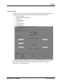
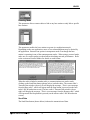
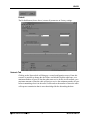
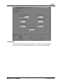
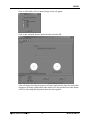
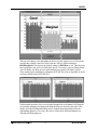
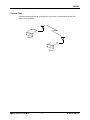
HN-591
900MHz Desktop Wireless Modem
User’s Guide
Important Regulatory Information
Cirronet Product FCC ID: HSW-910M
IC 4492A-910M
Note: This unit has been tested and found to comply with the limits for a Class A digital
device, pursuant to part 15 of the FCC Rules. These limits are designed to provide
reasonable protection against harmful interference when the equipment is operated in a
commercial environment. This equipment generates, uses, and can radiate radio
frequency energy and, if not installed and used in accordance with the instruction manual,
may cause harmful interference to radio communications. Operation of this equipment in
FCC s MPE Requirements
Information to user/installer regarding FCC s Maximum Permissible Exposure (MPE) limits.
Notice to users/installers using the 8.5 dBi Yagi antenna with the WIT910.
FCC rules limit the use of this antenna, when connected to the WIT910 module, to point-to-point
applications only. It is the responsibility of the installer to ensure that the system is prohibited
from being used in point-to-multipoint applications, omni-directional applications, and
applications where there are multiple co-located intentional radiators transmitting the same
information. Any other mode of operation using this antenna is forbidden.
Notice to WIT910 users/installers using the following fixed antennas:
Cushcraft 8.5 dBi Yagi
The field strength radiated by this antenna, when connected to a transmitting WIT910, may
exceed FCC mandated RF exposure limits. FCC rules require professional installation of these
antennas in such a way that the general public will not be closer than 23 cm from the radiating
aperture of this antenna. End users of these systems must also be informed that RF exposure
limits may be exceeded if personnel come closer than 23 cm to the aperture of this antenna.
Notice to WIT910 users/installers using the following fixed antennas:
Cushcraft 6 dBi Monopole Cushcraft 3 dBi Omni
Ace 2dBi dipole
The field strength radiated by any one of these antennas, when connected to a transmitting
WIT910, may not exceed FCC mandated RF exposure limits. FCC rules require professional
installation of these antennas in such a way that the general public will not be closer than 20 cm
from the radiating aperture of any of these antennas. End users of these systems must also be
informed that RF exposure limits may be exceeded if personnel come closer than 20 cm to the
apertures of any of these antennas.
Changes or modifications not expressly approved by the party responsible may void the users ability to
operate the equipment.
Table of Contents
Introduction ..................................................................................................................... 1
HopNet Frequency Hopping Spread Spectrum Advantages ........................................ 1
HopNet Data Integrity................................................................................................... 1
Flexible Power Management........................................................................................ 1
Data Transmission ....................................................................................................... 2
LED Status ................................................................................................................... 2
Power Connection ........................................................................................................ 2
Antenna Connection..................................................................................................... 2
Configuring the HN-591................................................................................................... 3
Overview ...................................................................................................................... 3
Introduction .............................................................................................................. 3
HopNet Configuration Wizard (HNWizard) ...................................................................... 4
Parameters Tab ....................................................................................................... 6
Network Tab............................................................................................................. 9
Protocol Tab........................................................................................................... 12
RF Tools ................................................................................................................ 14
Saving Configurations ............................................................................................ 18
Modem Commands ....................................................................................................... 18
Serial Commands....................................................................................................... 19
Set Data Rate Divisor............................................................................................. 19
Set Protocol Mode.................................................................................................. 20
Network Commands................................................................................................... 21
Set Transceiver Mode ............................................................................................ 21
Set Default Handle ................................................................................................. 21
Enable Global Network Mode ................................................................................ 22
Set Hopping Pattern............................................................................................... 22
Set Transmit Power................................................................................................ 22
Read Receive Signal Strength Indicator (RSSI)..................................................... 22
Protocol Commands................................................................................................... 23
Set Alternative Frequency Band............................................................................. 23
Set Hop Duration.................................................................................................... 24
Set Minimum Data Length...................................................................................... 24
Get Maximum Data Length (read only) .................................................................. 24
Set Maximum Number of Remotes (base only) ..................................................... 24
Set Packet Attempts Limit ...................................................................................... 24
Set Data Transmit Delay ........................................................................................ 25
Set Slot Assignment Mode (base station only)....................................................... 25
Set Base Slot Size (base station only) ................................................................... 25
Set ARQ Mode ....................................................................................................... 25
Status Commands...................................................................................................... 26
Banner Display Disable.......................................................................................... 26
Set Escape Sequence Mode.................................................................................. 26
Read Factory Serial Number High, Middle and Low Bytes. ................................... 27
Set Duty Cycle ....................................................................................................... 27
Memory Commands ................................................................................................... 28
Recall Factory Defaults .......................................................................................... 28
Recall Memory ....................................................................................................... 28
Store Memory......................................................................................................... 28
Modem Command Summary ..................................................................................... 29
Typical HopNet Applications ......................................................................................... 30
Introduction ................................................................................................................ 30
Point to Multipoint................................................................................................... 30
Point-to-Point ......................................................................................................... 31
Troubleshooting ............................................................................................................ 32
Overview .................................................................................................................... 32
Introduction ............................................................................................................ 32
Transceiver Requirements ..................................................................................... 32
Common System Problems........................................................................................ 33
Guidelines for Reducing Interference ......................................................................... 34
Introduction ............................................................................................................ 34
Guidelines for Selecting Your Site.......................................................................... 34
Guidelines for Avoiding Terrain Obstructions ............................................................. 34
Customer Support ......................................................................................................... 35
Introduction ................................................................................................................ 35
Technical Assistance.................................................................................................. 35
Factory Repairs .......................................................................................................... 35
Glossary of Terms ......................................................................................................... 36
Technical Specifications................................................................................................ 37
General ...................................................................................................................... 37
Mechanical ................................................................................................................. 37
Mechanical ................................................................................................................. 38
Environmental ............................................................................................................ 38
Appendix A.................................................................................................................... 39
HNWizard INIT.INI File............................................................................................... 39
HNWizard’s WinCom Window .................................................................................... 40
Function Keys ........................................................................................................ 43
Recover.................................................................................................................. 43
Restart ................................................................................................................... 44
Warranty........................................................................................................................ 45
HN-591
Introduction
The HN-591 provides reliable wireless connectivity for either point-to-point or pointto-multipoint applications. The HN-591 is built around the WIT910 radio transceiver,
which employs frequency hopping spread spectrum technology. This technology
ensures:
• Maximum resistance to noise
• Maximum resistance to multipath fading
• Robustness in the presence of interfering signals
In addition, the HN-591 includes a rechargeable battery pack allowing 2+ hours of
operation without mains power. Battery operation makes the HN-591 ideal for site
surveys. The sleek, rugged styling of the HN-591 enclosure enables deployment in
any environment.
HopNet Frequency Hopping Spread Spectrum Advantages
In the frequency domain, a multipath fade can be described as a frequency selective
notch that shifts in location and depth over time. Multipath fades typically occupy
five percent of the band. A conventional radio system typically has a five percent
chance of signal impairment at any given time due to multipath fading.
Frequency Hopping Spread Spectrum reduces the vulnerability of a radio system to
both interference from jammers and multipath fading by distributing or spreading the
signal over a larger region of the frequency band.
The fade resistant, HopNet frequency-hopping technology employs up to 54 channels
and switches channels over 40 times a second to achieve high reliability throughput.
HopNet Data Integrity
An on-board 512B buffer and error correcting over-the-air protocol ensure data
integrity even in the presence of weak signals or jammers. The serial interface
handles both data and control of asynchronous data rates of up to 115Kbps.
Flexible Power Management
The power can be set at 10 milliwatts, 100 milliwatts or 500 milliwatts using the
included software. Reduced power can reduce the size of the coverage zone, which
may be desirable for multiple network indoor applications. You can also place the
transceiver module in a power-save mode, which enables smart power management.
Smart power management allows a remote unit to drop into a lower current standby
mode during transmission or receiving gaps.
This feature also allows Hopnet products to be used in various countries where the
output power requirements may vary due to regulation.
© 2000- 2004 Cirronet™ Inc
1
M-910-0012 Rev A
HN-591
Data Transmission
The HN-591 can be used as either a base or as a remote. The HN-591 can usually
transmit to 1000 feet indoors and in excess of 20 miles outdoors under ideal
conditions.
The automatic repeat requests (ARQ) and multinode protocol are transparent to the
user equipment. User data rates of 115Kbps are supported with built-in CRC/ARQ
error protocols. Data signals are EIA RS-232 standard for Data Communications
Equipment (DCE) devices.
Data and control of the radio are passed through a standard DB9 connector. See the
following illustration for the signal description.
LED Status
The four LED indicators are included on the front panel to provide the status of the
HN-591 Indoor Base/Remote station. See the illustration below. These built-in flow
control indicators allow you to quickly check the operational status.
PWR
TX
RX
CD
The table below describes the function of each LED.
Name
Color
Description
PWR
Green/Red
Continuous DC power is applied
TX
Red
RS-232 signal input
RX
Red
RS-232 signal output
CD
Red
Normal operation is asserted
Power Connection
The HN-591 is supplied with a 110VAC wall mount power supply. However, you can
operate the HN-591 from any well-filtered 5 VDC power source. The power supply
should be capable of providing 1 Amp of current.
The HN-591 also has a built in battery pack that allows use of the modem without
being tethered to a power source. The battery pack charges any time the unit is
plugged in. An amber colored LED on the rear of the unit next to the power
connector indicates that the internal battery pack is charging.
Antenna Connection
The RF signal is brought in on a reverse male SMA jack connector located on the
back panel. The HN-591 comes with a 2 dB omni-directional antenna. Be sure to
securely fasten the antenna.
© 2000- 2004 Cirronet™ Inc
2
M-910-0012 Rev A
HN-591
Configuring the HN-591
Overview
Introduction
You can configure the HopNet network using the HNWizard software provided or a
PC running a terminal emulation program. HNWizard is a software package that runs
under Windows 98/NT/2000/XP. This chapter provides the information you need to
configure your HN-591.
The HN-591 is shipped from the factory initially configured as a remote with a 9600
baud rate.
© 2000- 2004 Cirronet™ Inc
3
M-910-0012 Rev A
HN-591
HopNet Configuration Wizard (HNWizard)
Open the Wizard by double-clicking on the icon on the desktop. When the Wizard
boots up, it will automatically detect the serial port to which the HopNet radio is
connected and its baud rate. This process takes a few seconds to complete. During
this process, the “Please wait” screen is displayed. Once the radio has been found and
the Baudrate determined, the “Finished” screen is displayed. Click on the Continue
button to enter the Wizard.
NOTE: HNWizard is used with a variety of Cirronet radios. Not all radios support
all the functions and features of every Cirronet radio. Thus, some selections in the
Wizard will be grayed out if they are not applicable to the radio in use.
After detecting the serial port and baud rate of the HopNet radio, the Wizard reads the
settings of the HopNet radio that is connected to the PC and will display them in the
various parameter windows. In the bottom left corner of the Wizard window, the
Base/Remote status, the serial number and the communication port are always
displayed.
NOTE: The S/N displayed in the bottom left corner is the serial number of the
radio inside the unit and is different from the serial number of the HopNet unit.
Both the HopNet unit serial number and the radio serial number are on the radio
unit of the HopNet product. The Wizard will also prompt to save the configuration
settings to a file.
© 2000- 2004 Cirronet™ Inc
4
M-910-0012 Rev A
HN-591
When a parameter value is changed from the value currently in the HopNet radio, the
parameter label and value will turn red and the Apply Settings button will appear.
When the value is changed back to the value that is currently in the attached HopNet
radio, the label and parameter value will return back to black. When new values are
applied to the HopNet radio, the red values will turn black indicating the updated
values in the radio.
NOTE The changes are not sent to the HopNet radio until the Apply Settings
button is clicked.
Context sensitive help is available through the F1 key or Help menu.
© 2000- 2004 Cirronet™ Inc
5
M-910-0012 Rev A
HN-591
Parameters Tab
The Wizard program opens the main screen with the Parameters Tab displayed. The
parameters screen of the Wizard allows the following variables to be set;
1. Base or Remote
2. Point-to-Point or Multipoint
3. Baud rate
4. Network number
5. Lockout Key
6. Roaming Mode
7. Protocol Mode
Depending on whether HopNet radio is configured as a Remote or Base when first
connected, the heading on the Parameters page will display either “Remote
Parameters” or “Base Parameters.”
© 2000- 2004 Cirronet™ Inc
6
M-910-0012 Rev A
HN-591
Network Number
This parameter is also known as Set Hopping Pattern. By using different network
numbers or “hopping patterns”, nearby or co-located networks can avoid interfering
with each other’s transmissions.
BaudRate
Sets the serial bit rate between the modem and the host.
Lockout Key
This parameter allows further network segregation beyond the network number. This
feature allows multiple co-located networks in which global roaming is enabled. By
using different lockout keys, the bases to which remotes link can be limited or
segregated.
Serial Port Settings
This parameter is only available on radios with Modbus adapters. It allows the setting
of even, odd or no parity, 7 or 8 data bits and 1 or 2 stop bits.
© 2000- 2004 Cirronet™ Inc
7
M-910-0012 Rev A
HN-591
Roaming Mode
This parameter allows remote radios to link to any base station or only link to specific
base stations.
Protocol Mode
This parameter enables the base station to operate in a multipoint network.
Depending on the user application, more or less acknowledgment may be desired by
the application. Remotes can operate in transparent mode even though the base
station is operating in one of the nontransparent modes. When using a protocol mode,
make sure to count in packet overhead when calculating network performance. Refer
to the section on Protocol Modes for details on each format.
When the radio is linked to another radio, a communications test can be run by
clicking on the Send Data button (shown below) on both radios. The remote radio’s
Transmit Data window (above left) will display the message, “This is a test message
from the Base radio”, which will repeat until the Stop button is pressed (on the base
radio’s HN Wizard main screen). The base radio’s Transmit Data window (above
right) will display the message, “This is a test message from the Remote radio” which
will repeat until the Stop button is pressed (on the remote radio’s HN Wizard main
screen).
Send Data
The Send Data button (shown below) initiates the transmission of data.
© 2000- 2004 Cirronet™ Inc
8
M-910-0012 Rev A
HN-591
Default
The Default button (shown above) returns all parameters to Factory settings.
Network Tab
Clicking on the Network tab will bring up a second configuration screen. From this
screen it is possible to change the dwell time at which the HopNet radio hops, set a
minimum number of bytes of data the radio must receive before it will transmit, set a
maximum amount of time the radio will wait to receive the minimum number of bytes
before transmitting what is in the radio’s buffer and set the number of times the radio
will repeat a transmission that is not acknowledged before discarding the data.
© 2000- 2004 Cirronet™ Inc
9
M-910-0012 Rev A
HN-591
Set Data Transmit Delay
When used in conjunction with the minimum data length parameter, sets the amount
of time from the receipt of a first byte of data from the host until the radio will
transmit in transparent mode. Default is 0.0ms which causes transmission to occur
without any delay. When a host is sending a group of data that needs to be sent
together, setting this parameter will provide time for the group of data to be sent by
the host before the radio transmits. If the length of data to be sent together is longer
than the time slot can send, the data will not be sent together but will be broken up
over multiple hops. The length of time the radio will wait is equal to the specified
value times the hop duration.
NOTE: The Transmit Delay is specified as a number of hop durations and thus will
be an integer multiple of the Hop Duration. The Maximum Base Packet can only
be set in radios set as a base. If the radio is a remote, this value cannot be changed.
Maximum Base Packet (base station only)
This command sets the amount of time allocated for transmission on each hop for the
base station time slot in 4-byte increments. If using a protocol mode, attempting to
send a packet with a length longer than this setting will cause the packet to be
discarded.
Set Minimum Data Length
This command sets the minimum threshold number of bytes required to form a packet
in transparent mode. The radio will wait until the data transmit delay elapses before
sending a data packet with less than this number of bytes. This parameter can be used
to keep short, intermittent transmissions contiguous. In packet modes, the length
parameter in the data packet will override this value. This value is subject to the
maximum data length even in packet mode.
© 2000- 2004 Cirronet™ Inc
10
M-910-0012 Rev A
HN-591
Set Packet Retries
If ARQ Mode is set to 0, it sets the number of times the radio will attempt to send an
unsuccessful transmission before discarding it. If ARQ Mode is set to 1, it is the
number of times every transmission will be sent, regardless of success or failure of a
given attempt. When this parameter is set to 255, RF flow control mode is entered for
transmissions from the radio. This mode can be entered for one or both radios in a
point-to-point system. Using this mode in a point-to-multipoint system will stop
transmissions to all radios when any one radio has a full buffer.
Set Hop Duration
This command sets the length of time the transceiver spends on each frequency
channel. A smaller value will allow the remote to lock on to the base signal faster at
system startup, and will generally decrease packet latency. A larger value increases
network capacity, due to decreased overhead in channel switching. This Set Hop
Duration value only needs to be set in the base which broadcasts the parameter to all
remotes. However, link time can be reduced if this value is also programmed into the
remotes, which use it as a starting value when scanning for the base.
The speed at which the radio hops affects both latency and throughput. The faster the
radio hops, the shorter the latency but the lower the throughput. The minimum packet
length and packet timeout allow fixed-length packets of data to be transmitted on a
single hop without leaving data stuck in the radio’s transmit buffer.
NOTE: If the hop speed is too fast, there may not be time to send a long packet on a
single hop.
Refer to the Protocol Commands section of this manual for details on these
commands.
© 2000- 2004 Cirronet™ Inc
11
M-910-0012 Rev A
HN-591
Protocol Tab
The Protocol tab brings up the configuration screen above. On the next page are
descriptions of the commands/parameters that are available for modification.
© 2000- 2004 Cirronet™ Inc
12
M-910-0012 Rev A
HN-591
Set the Frequency Operating Range
by clicking on the drop-down menu
and making a selection. ¹
Set Radio Power Setting up by
clicking on a selection. ²
Note: This list will change depending
on which radio is being used.
Set Redundant Transmit by
selecting either ARQ enabled or ARQ
disabled.
Set Maximum Number of Remotes
from1 to 62.
Choose to have the Banner Display
or not by selecting Banner disabled or
Banner enabled.
Choose the type of Escape Sequence
by selecting Once after reset or
Unlimited times.
¹ The selections in this field will change depending on the frequency band the radio operates in. For 2.4GHz
radios, selecting one of the 802.11b bands in which to operate, the HopNet radio can be used in locations with
802.11b networks without causing interference with those networks. If there are no 802.11b networks present, it
is recommended that the radio be set to operate in the entire band which is the default. For 900MHz radios, there
will only be two bands to select.
² The Radio Power Setting controls how much power is used to transmit data. Unless the HopNet radio operates in
the 2.4GHz band and is being used in the European Union (EU) this setting should be left at the default High
Power. Because of the built-in antenna of the HopNet radio, the 10mW power setting must be used when
operating in an EU country.
© 2000- 2004 Cirronet™ Inc
13
M-910-0012 Rev A
HN-591
RF Tools
Clicking on the RF Tools tab brings up a screen that allows the receive signal strength
to be monitored and the link quality to be observed. Range Optimization may be
grayed out on certain radios.
NOTE: RF Tools only work on HopNet radios operating as remote radios. The
radio must be linked with its base radio for the functions on this screen to work.
Range Optimization (HopNet 10 Series only)
This command automatically applies an adjustment factor to the over-the-air timing
of remotes to compensate for the effects of propagation delay at long ranges. Simply
click on the radio button opposite Range Optimization and the following screen will
display.
© 2000- 2004 Cirronet™ Inc
14
M-910-0012 Rev A
HN-591
Click on OK and the Select Connect Range screen will appear.
Click on the estimated distance between radios and click OK.
A bar will appear showing the progress of Range Optimization. Once the process has
completed, the Range Optimization radio button will clear and the Done radio button
will fill in indicating that adjustment factor has been applied.
© 2000- 2004 Cirronet™ Inc
15
M-910-0012 Rev A
HN-591
Receive Only and Bi-Directional Transmissions
The Receive Only function displays the percentage success rate for receiving
transmissions from the base. This is an indication of how well the remote HopNet
radio “hears” the base. The Bi-Directional function provides a round-trip success rate.
That is, the base must successfully receive data from the remote and the remote must
successfully receive data from the base. In theory, this percentage should be the
square of the Receive Only percentage. If it is substantially less, it is an indication
that the base HopNet radio is having difficulty “hearing” the remote. Good RF links
will have the Receive Only percentage above 95% and the Bi-Directional percentage
above 90%. These functions operate with the Automatic Retransmit Request (ARQ)
disabled and as such provide an indication of link quality but do not provide an
indication of how often data will get through since in normal operation ARQ is
enabled and the radio automatically and transparently will resend data that was not
received on the first attempt.
NOTE: The Options menu allows for bar graph display (in addition to the pie chart
display) of the Receive Good Packets and Bi-Directional Good Packets data.
Received Signal Strength Indication.
This function will display on a channel basis, the strength of the signal received from
the base by the remote. The values on the Y-axis are only approximate and should not
be used as absolute reading values.
© 2000- 2004 Cirronet™ Inc
16
M-910-0012 Rev A
HN-591
The bars will change color depending on the level of the signal received. The points
at which they change color have been set in the .INI file, default setting for
RSSIMarginal is -60 whereas the default setting for RSSIPoor is -80. Therefore any
bars rising above the -60 level will display green. Conversely, any bars falling below
-80 will display red. Bars at levels between these two points will display yellow.
These points can be modified by editing the INIT.INI file (refer to Appendix A in the
section on HNWizard’s INIT.INI file).
Under normal operation, the received signal strength for each channel will fluctuate,
occasionally dropping to nothing indicating the hop was missed by the radio. This
display also shows multipath fading when a channel drops noticeably below the
surrounding channels. Over time, one can see clearly how different channels are
affected to differing degrees.
© 2000- 2004 Cirronet™ Inc
17
M-910-0012 Rev A
HN-591
Saving Configurations
Configuration settings that have been applied from the Wizard can be saved for future
use. The Wizard prompts to save changes on initial boot-up, after changes have been
applied and on exiting the Wizard if the changes have not previously been saved. The
default filename for the configuration settings is “hn_xxxxxx.cfg” where xxxxxx is
the serial number of the radio in the HopNet (This serial number is also on the outside
of the radio). To save a configuration under another filename, simply enter the
desired filename in the dialog box. Once a configuration has been saved, it can be
used to set up additional HopNet radios with the same configuration by clicking on
the Load command on the File menu. You will be prompted for a filename to load.
Loading the file will load the parameters into the Wizard program but will not
program the settings into the HopNet radio until the Apply Settings button is clicked.
Modem Commands
The HopNet is configured and controlled through a series of commands. These
commands are sent to the modem directly when the modem is in Control Mode or
when the modem is in Data Mode if the escape sequence is enabled. The command
syntax is the same for either method, a one- or two-letter command followed by one
or more parameters. The modem will respond with a two-byte message that indicates
the new modem parameter value. The commands are loosely grouped into five
different categories: Serial commands, Network commands, Protocol commands,
Status commands and Memory commands. Each command is described in detail
below. In the descriptions, brackets ([,]) are used to denote a set of optional
arguments. Vertical slashes (|) separate selections. For example, given the string
wn[?|0..3f], some legal commands are wn?, wn0, wn3 and wna. Most commands
which set a parameter also have a ? option which causes the modem to respond with
the current parameter setting, e.g., wn? Each modem command must be followed by
either a carriage return or a line feed.
© 2000- 2004 Cirronet™ Inc
18
M-910-0012 Rev A
HN-591
Serial Commands
These commands affect the serial interface between the modem and the host. The
default settings are 9600 bps and protocol mode 0.
Command
sd[?|02..FF]
Description
Set Data Rate Divisor
Data Rate Divisor (hex)
2400 bps =
8F
9600 bps =
23
14400 bps =
17
19200 bps =
11
28800 bps =
B
38400 bps =
8
57600 bps =
5
115200 bps =
2
sp[?|00..14]
Set Protocol Mode
00
= point-to-point transparent mode
01
= basic command and data only
02
= command, data and connection notification
03 – 08 = reserved for future use
09
= mode 01 during transmit, transparent receive
0A
= mode 02 during transmit, transparent receive
0C – 10 = reserved for future use
11
= transparent transmit, mode 01 during receive
12
= transparent transmit, mode 02 during receive
Set Data Rate Divisor
Sets the serial bit rate between the modem and the host. This command takes effect
immediately and will require adjusting the host serial rate to agree. Nonstandard rates
may be programmed by entering a data rate divisor computed with the following
formula:
DIVISOR = (345600/RATE)-1
Round all non-integer values down.
© 2000- 2004 Cirronet™ Inc
19
M-910-0012 Rev A
HN-591
Set Protocol Mode
Enables the base station to operate in a multipoint network. Depending on the user
application, more or less acknowledgment may be desired by the application.
Remotes can operate in transparent mode even though the base station is operating in
one of the nontransparent modes.
When using a protocol mode, make sure to count in packet overhead when calculating
network performance. Refer to the section on Protocol Modes for details on each
format.
© 2000- 2004 Cirronet™ Inc
20
M-910-0012 Rev A
HN-591
Network Commands
Network commands are used to set up a HopNet network and to set radio addressing
and configuration.
Command
wb[?|0|1]
Description
Set Transceiver Mode
0 = remote (default)
1 = base station
wd[?|1-3f] (base
only)
Set Default Handle
Used to override automatic handle assignment by the base station
30 = default
wg[?|0|1]
Enable Global Network Mode
0 = Link only to hop pattern specified by wn parameter (default)
1 = Link to any hop pattern, regardless of wn parameter
Set Hopping Pattern (Network Number)
0 = default
wn[?|0-1f]
wp[?|0|1|2]
Set Transmit Power
0 = 10mW
1 = 100mW (default)
2 = 500mW
wr?
Read Receive Signal Strength (remote only)
Set Transceiver Mode
Sets modem operation as either base station or remote. Default is remote.
Set Default Handle
This handle will override the automatic handle assignment by the base station. When
specified for the base, the default handle determines which remote it will address
when transparent protocol mode is in effect. When 3FH is specified for the base,
broadcast mode is entered.
© 2000- 2004 Cirronet™ Inc
21
M-910-0012 Rev A
HN-591
Enable Global Network Mode
For networks with multiple base stations, remotes are ordinarily only able to link to
one base station, set by the hopping pattern. Mode 1 enables the global mode that
allows remotes to link to any base station they can hear, acquiring whatever hop
pattern is required. In this mode a remote can only change base stations once it is no
longer registered with a base station. Bases and remotes must be set to the same
mode.
Set Hopping Pattern
The HopNet has 32 preprogrammed hopping patterns (also referred to as network
numbers). By using different hopping patterns, nearby or co-located networks can
avoid interfering with each other’s transmissions. Even if both networks tried to use
the same frequency, on the next hop they would be on different frequencies.
Set Transmit Power
The HopNet has three preset transmit power levels, 10mW (10dBm), 100mW
(20dBm) and 500mW (27dBm). Control of the transmit power is provided through
this command. Default is 100mW.
Read Receive Signal Strength Indicator (RSSI)
This command reports the relative signal strength averaged over the last 10 hops.
This command returns a one byte value that is proportional to received signal strength
and can range from 00H to FFH. Typical values range from 30H to 80H where the
lower the number the lower the received signal strength and the higher the number the
higher the received signal strength. This is a relative indication and does not directly
correspond to a field strength number. This is available only at the remotes as the
base station is the only source that transmits on a regular basis. Plus, in a point-tomultipoint network the base will receive different signal strengths from each remote.
© 2000- 2004 Cirronet™ Inc
22
M-910-0012 Rev A
HN-591
Protocol Commands
These commands can be used to tune the transceiver for optimum transmission of
data across the RF link. For most applications, the default values are adequate.
Command
Description
pe[?|0-1]
Set Alternative Frequency Band
0 = 902.5MHz to 926.2MHz (default)
1 = 902.5MHz to 924.4MHz
ph[?|00-fe]
Set Hop Duration
87 = default (=25ms)
pk[?|00-d0]
Set Minimum Data Length
01 = default
pl?
(remote only)
pn[?|01-3e]
(base only)
Get Maximum Data Length (read only)
D4 = default (=212 bytes)
Set Maximum Number of Remotes
3e = default (=62 remotes)
pr[?|00-ff]
Set Packet Attempts Limit
10H = default
FFH = Infinite retry (RF flow control point-to-point only)
pt[?|00-ff]
Set Data Transmit Delay
00H = default
pv[?|0|1]
Set Slot Assignment Mode
(base only)
0 = default (dynamic slot assignment)
1 = static slot assignment
pw[?|00-2f]
(base only)
px[?|0|1]
Set Base Slot Size
08H = default (=32 bytes)
Set ARQ mode.
0 = ARQ enabled (default)
1 = ARQ disabled (redundant transmission)
Note: Incorrect setting of these parameters may result in reduced throughput or loss of data
packets.
Set Alternative Frequency Band
When set to 0, limits the operating RF channel between 902.5MHz to 926.2MHz
(default). When set to 1, limits the operating RF channel between 902.5MHz to
924.4MHz.
© 2000- 2004 Cirronet™ Inc
23
M-910-0012 Rev A
HN-591
Set Hop Duration
Sets the length of time the transceiver spends on each frequency channel. A smaller
value will allow the remote to lock on to the base signal faster at system startup, and
will generally decrease packet latency. A larger value increases network capacity,
due to decreased overhead in channel switching. The hop duration is specified in
185.2µs increments. The default value of 87H corresponds to a duration of 25ms.
The maximum value of FEH is 47.02ms. For best results, do not specify a duration of
less than 15 ms.
Set Minimum Data Length
This sets the minimum threshold number of bytes required to form a packet in
transparent mode. The radio will wait until the data transmit delay elapses before
sending a data packet with less than this number of bytes. Can be used to keep short,
intermittent transmissions contiguous. In packet modes, the length parameter in the
data packet will override this value. This value is subject to the maximum data length
even in packet mode. See Get Maximum Data Length below.
Get Maximum Data Length (read only)
This parameter indicates the largest number of bytes that a remote will transmit per
hop, based on the size of the slot it has been allocated by the base. In general more
remotes mean less data can be transmitted per remote. By reading this parameter and
dividing by the hop duration, the remote's data rate capacity can be determined.
Attempting to send protocol mode packets longer than maximum data length will
result in the packet being discarded without being sent. See the section on the
tradeoffs between hop duration and data length.
Set Maximum Number of Remotes (base only)
This parameter limits the number of remotes that can register with a given base. The
default is 62 remotes which is the maximum number of remotes that can be registered
with a base at one time. This command is useful when used in conjunction with
global roaming for load balancing when base stations are collocated. It is also useful
to assure a minimum remote throughput.
Set Packet Attempts Limit
If ARQ Mode is set to 0, sets the number of times the radio will attempt to send an
unsuccessful transmission before discarding it. If ARQ Mode is set to 1, it is the
number of times every transmission will be sent, regardless of success or failure of a
given attempt. When this parameter is set to FFH, RF flow control mode is entered for
transmissions from the radio. This mode can be entered for one or both radios in a
point-to-point system. Using this mode in a point-to-multipoint system will stop
transmissions to all radios when any one radio has a full buffer or if the base radio
attempts to send data to a remote that has recently (<7 seconds) left the range of the
base..
© 2000- 2004 Cirronet™ Inc
24
M-910-0012 Rev A
HN-591
Set Data Transmit Delay
When used in conjunction with the minimum data length parameter, this sets the
amount of time from the receipt of a first byte of data from the host until the radio
will transmit in transparent mode. Default is 00H which causes transmission to occur
without any delay. When a host is sending a group of data that needs to be sent
together, setting this parameter will provide time for the group of data to be sent by
the host before the radio transmits. If the length of data to be sent together is longer
than the time slot can send, the data will not be sent together but will be broken up
over multiple hops. The length of time the radio will wait is equal to the specified
value times the hop duration.
Set Slot Assignment Mode (base station only)
Sets whether the base station will assign remote transmit slots dynamically, based on
the number of remotes currently registered or whether the base station will assign
remote transmit slots statically, based on the maximum number of remotes parameter.
If static slot assignment is selected, make sure maximum number of remotes is
correctly set. Otherwise remote transmit performance will suffer as transmit time will
be reserved for remotes that may not exist. The dynamic assignment mode will
generally be preferred; however, the static assignment mode will result in a static
maximum data length parameter.
Set Base Slot Size (base station only)
Sets the amount of time allocated for transmission on each hop for the base station
time slot in 4-byte increments. Maximum value is 2FH which corresponds to 188
bytes. If using a protocol mode, attempting to send a packet with a length longer than
this setting will cause the packet to be discarded.
Set ARQ Mode
Sets ARQ mode when set to 0 which is the default. In this mode the radio will resend
an unsuccessful transmission until either successful or packet attempt limit attempts
have been made. When set to 1 selects redundant transmit mode that will send every
transmission packet attempt limit times regardless of success or failure of any given
attempt. When redundant transmit mode is used, receiving radios will discard all
subsequent retransmissions once the transmission has been successfully received.
Thus the receiving host will receive just one copy of the transmission.
© 2000- 2004 Cirronet™ Inc
25
M-910-0012 Rev A
HN-591
Status Commands
These commands deal with general interface aspects of the operation of the HopNet.
Command
Description
zb[?|0|1]
Banner Display Disable
0 = disabled
1 = enabled (default)
zc[?|0..2]
Set Escape Sequence Mode
0 = disabled
1 = once after reset (default)
2 = unlimited times
zh?
Read factory serial number high byte.
zm?
Read factory serial number middle byte.
zl?
Read factory serial number low byte.
zp[?|0-5]
Set the duty cycle at which the modem will wake up to send and
receive data. Duty cycle equals 1/2N where the argument of the
command equals N.
(base only)
z>
Exit Modem Control Mode
Banner Display Disable
Enables or disables display of the banner string and revision code automatically at
power-up. May be disabled to avoid being mistaken for data by the host.
Set Escape Sequence Mode
Enables or disables the ability to use the in-data-stream escape sequence method of
accessing Control Mode by transmitting the string ":wit2410". When this mode is set
to 1, the escape sequence only works immediately after reset (this is the default).
When set to 2, the escape sequence may be used at any time in the data stream when
preceded by a pause of 20 ms. For backwards compatibility with the WIT2400, the
string ":wit2400" is also accepted for entering Control Mode. Note that the escape
sequence must be interpreted as data by the radio until the last character is received,
and as such will be transmitted to a receiving radio station.
© 2000- 2004 Cirronet™ Inc
26
M-910-0012 Rev A
HN-591
Read Factory Serial Number High, Middle and Low Bytes.
These read only commands return one of the three bytes of the unique factory-set
serial number, which are also visible in the startup banner.
Set Duty Cycle
Allows reduced power consumption by having a remote wake up only every 2N hops
to receive and transmit. Power consumption is roughly proportional to the duty cycle
selected. For example, if N=2, the remote will wake up every fourth hop. Power
consumption will be roughly ¼ the consumption as when N=0. This parameter must
be set to the appropriate value when more than 16 remotes are in use.
© 2000- 2004 Cirronet™ Inc
27
M-910-0012 Rev A
HN-591
Memory Commands
The user is able to store a configuration in nonvolatile memory, which is loaded
during the initialization period every time the radio is powered up. Note that changes
to the serial port baud rate- from recalling the factory defaults or recalling memory will not take effect until DTR is toggled or power to the radio is cycled.
Command
Description
m0
Recall Factory Defaults
m<
Recall Memory
m>
Store Memory
Recall Factory Defaults
Resets the HopNet to its factory default state. This is useful for testing purposes or if
there is a problem in operation of the system and the configuration is suspect. Use
the Store Memory command afterwards if you wish the factory default settings to be
remembered the next time you cycle power or reset the radio.
Recall Memory
Useful for restoring the power-on settings after experimenting with temporary
changes to data rate, protocol or network parameters, etc.
Store Memory
This command is necessary after any command to change the data rate, transceiver
address, or other radio setting that you wish to make permanent.
© 2000- 2004 Cirronet™ Inc
28
M-910-0012 Rev A
HN-591
Modem Command Summary
sd[?|02..8f]
sp[?|00..14]
Serial Commands
Set Data Rate Divisor
Set Protocol Mode
wb[?|0|1]
wd[?|1..3f]
wn[?|00..1f]
wg[?|0|1]
wp[?|0|1|2]
wr?
dx[?|0..62]
Network Commands
Set Transceiver Mode
Set Default Handle
Set Hopping Pattern
Enable Global Network Modes
Set Transmit Power
Read Receive Signal Strength (remote only)
Set Range Optimization (remote only)
pe[?|0|1]
ph[?|00..fe]
pl?
pn[?|01..3e]
pk[?|00..d4]
pr[?|00..ff]
pt[?|00..ff]
pv[?|0|1]
pw[?|00..2f]
px[?|0|1]
Protocol Commands
Set Alternative Frequency Band
Set Hop Duration (base only)
Get Maximum Data Length
Set Maximum Number of Remotes(base only)
Set Minimum Data Length
Set Packet Attempts Limit
Set Data Transmit Delay (remote only)
Set Slot Assignment Mode (base only)
Set Base Slot Size (base only)
Set ARQ Mode
Status Commands
Banner Display Disable
Set Escape Sequence Mode
Read Factory Serial Number High Byte
Read Factory Serial Number Middle Byte
Read Factory Serial Number Low Byte
Set Duty Cycle(base only)
Exit Modem Control Mode
zb[?|0|1]
zc[?|0..2]
zh?
zm?
zl?
zp[?|0..4]
z>
Memory Commands
Recall Factory Defaults
Recall Memory
Store Memory
m0
m<
m>
© 2000- 2004 Cirronet™ Inc
29
M-910-0012 Rev A
HN-591
Typical HopNet Applications
Introduction
The illustration below shows a complete network of multiple data sources connected
to a central base. Units that are out of range are connected through a repeater. See the
illustration of a point-to-point application on the next page.
Point to Multipoint
This common application consists of a central host and remote terminal units or other
data collection devices. The automatic repeat requests (ARQ) and acknowledgments
inside the radio are transparent to the computer system.
HN-591
HN-591
HN-591
© 2000- 2004 Cirronet™ Inc
30
M-910-0012 Rev A
HN-591
Point-to-Point
A point-to-point application as shown below provides a communication data link
between two locations.
HN-591
HN-591
© 2000- 2004 Cirronet™ Inc
31
M-910-0012 Rev A
HN-591
Troubleshooting
Overview
Introduction
Troubleshooting the HopNet products is not difficult, but it does require a logical
approach. It is best to begin troubleshooting at the base station because the rest of the
system synchronizes to it. If the base station has problems, the entire network will be
compromised.
This chapter provides troubleshooting information for your HopNet products.
Transceiver Requirements
For proper operation, all transceivers in the network must meet these basic
requirements:
• Adequate and stable power
• Secure connections ( Power, RF, and Data)
• Proper programming especially Hop Duration and Network Address
© 2000- 2004 Cirronet™ Inc
32
M-910-0012 Rev A
HN-591
Common System Problems
The following table offers suggestions for resolving some common system problems
that the operator may experience from the radio system. If problems persist, contact
the factory for further assistance.
Problem
System Checks
Unit is inoperative
1. Check for proper DC voltage at the power
connector.
2. Momentarily remove and reapply power.
No Carrier Detect at
remote units or
intermittent
1. Check for secure interface connections at the
transceiver.
2. Check antenna, feedline, connectors, and reflective
power.
3. If remote unit is in synchronization but
performance is poor, it may indicate antenna
problems. Check for properly aligned antenna
headings.
4. Verify proper programming of the system
parameters.
Interference is
suspected
1. Verify that the system has a unique network
address. Nearby systems with same address will
cause interference problems.
2. If Omni-directional antennas are used with the
remote units, consider using a directional type
instead. This will often limit interference to and
from other stations.
3. Check RSSI value at the remote. A low value
would correspond to a weak signal strength.
© 2000- 2004 Cirronet™ Inc
33
M-910-0012 Rev A
HN-591
Guidelines for Reducing Interference
Introduction
The transceivers share the same frequency spectrum with other services and other
Part 15 devices in the US. Because of this, you may not achieve 100 percent error free
communications in a given location. You should also expect some level of
interference. However, the flexible design of the radio and the hopping pattern should
allow for adequate performance as long as care is taken in choosing station location,
configuration parameters of the transceivers, and protocols techniques.
Use the following guidelines to reduce interference in your HopNet system.
Guidelines for Selecting Your Site
Use these guidelines to select a proper site for the master remote stations. Suitable
sites must provide the following:
• An adequate and stable source of primary power.
• Antenna location that provides an unobstructed transmission path in the direction of
the associated units.
• Proper antenna selection, data access, and feedline cabling
Guidelines for Avoiding Terrain Obstructions
The HopNet transceivers operate in the 900MHz frequency band. While this band
offers many advantages, it is prone to signal attenuation from obstructions such as
terrain, foliage, buildings and anything else in the transmission path.
Use the following guidelines to avoid terrain obstructions:
• A line-of-sight transmission path between the base and the associated remote sites
provides for the most reliable transmission path.
• A line-of-sight path can be achieved by mounting the station antenna on a tower or
elevated structure that raises it to a sufficient level to clear surrounding terrain and
other obstructions.
• The importance of a clear transmission path relates closely to the distance to be
covered. If the system is to cover only a limited geographical area such as 1-3
miles, then some obstructions may be tolerated with minimal impact.
• For longer-range systems, any substantial obstruction in the transmission path
could compromise the performance of the system.
© 2000- 2004 Cirronet™ Inc
34
M-910-0012 Rev A
HN-591
Customer Support
Introduction
Cirronet, Inc. products are designed for long life and trouble free operation. The
following information is provided if servicing becomes necessary.
Technical Assistance
Technical assistance for Cirronet products is available during the hours of 9:00 A.M –
5:30 P.M. Eastern Standard Time. When calling, please have available the complete
model name, serial number, and a complete description of the problem. Most
problems can be resolved without returning the unit to the factory.
The following telephone numbers are available for assistance.
Phone
678-684-2000
Fax
678-684-2001
Factory Repairs
If return of equipment is necessary, you will be issued a Return Material
Authorization number (RMA #). The RMA # will help expedite the repair so that
equipment can be returned as quickly as possible. Please be sure to include the
RMA number (#) on the outside of the shipping box and on any correspondence
relating to the repair. Any equipment returned without an RMA # may be delayed in
the repair cycle.
Please be sure to carefully package all items to be returned and address to:
CIRRONET, INC.
5375 Oakbrook Parkway
Norcross, GA 30093
RMA # ***
© 2000- 2004 Cirronet™ Inc
35
M-910-0012 Rev A
HN-591
Glossary of Terms
Refer to the following list of terms that may be unfamiliar to you. These terms are
used throughout this document.
Definition
Term
ARQ
Automatic Repeat Request. The operation in which the radio
will re-send the data until it is received correctly.
bps
Bits-per-second. A measure of information transfer rate of
digital data across a channel.
Decibel
A measure of the ratio between two signal levels. Used to
express either loss or gain.
dBi
Decibels referenced to an ideal isotropic radiator in free space.
Used to express antenna gain.
dBm
Decibels referenced to 1 milliwatt. An absolute unit used to
measure signal power. Transmitter power output or received
signal strength.
DCE
Data Communications Equipment. A device that receives data in
the form of digital signals at its input. The modem side of a
computer-to-modem connection.
DCD
Data Carrier Detect.
DTE
Data Terminal Equipment. A device that provides data in the
form of digital signals at its output. The computer side of a
computer-to-modem connection.
EIRP
Effective Isotropic Radiated Power.
ISM
Industrial, Scientific, or Medical band operating at 2.4 GHz.
Allows use of a radio without a license, but the equipment must
be immune to interference from other users in the band and
approved for use in the intended country.
Latency
The delay between when data is received on TX until it is output
on RX.
RMA
Return Material Authorization.
RTU
Remote Terminal Unit. A device used in data collection.
TDMA
Time Division Multi Access. A time slot multiplexing protocol
for multinode networking.
© 2000- 2004 Cirronet™ Inc
36
M-910-0012 Rev A
HN-591
Technical Specifications
General
Specification
Value
Frequency Band
•
902 to 927MHz (USA)
Number of Channels
•
54 US
Approvals
•
US FCC: Part 15. 203
Data Rate
•
Up to 115Kbps Async Throughput
Channel Data Rate
•
172.8Kbps
Serial Data Interface
•
RS-232 Async
Network Protocol
•
ARQ: E/TDMA
TX Power Output
•
+27 dBm
Receive Sensitivity
•
-104 dBm for 10-5 BER
RF Bandwidth
•
172KHz
Modulation Type
•
GMSK
Output Impedance
•
50 Ω
Antenna Connector
•
Reverse SMA RF Jack
Input Power at
Connector
•
•
5 VDC Operating
200 mA Typical (750 mA surge)
5 Ground
9 Not Used
4 Not Used
8 Clear to Send (CTS)
3 Transmit Data (TX)
7 Request to Send (RTS)
2 Receive Data (RX)
6 Data Set Ready (DTR)
1 Data Carrier Detect (DCD)
© 2000- 2004 Cirronet™ Inc
37
M-910-0012 Rev A
HN-591
Mechanical
Specification
Value
Case
•
Metal
Size
•
•
5 in. x 3.5 in. x 1 in.
127mm x 89mm x 25mm
Weight
•
•
0.5 lb
227 g
Data Connector
•
DB-9 Receptacle
Environmental
Specification
Value
Temperature Range
•
0° to 40° C
Humidity
•
95% at +40°C, Non-condensing
© 2000- 2004 Cirronet™ Inc
38
M-910-0012 Rev A
HN-591
Appendix A
HNWizard INIT.INI File
One of the files unpacked with the program is the INIT.INI file. It contains the entries
below and an explanation has been included on how each parameter may be used.
ErrorLevel=0
Leave this value as is. Only change it at the request of Cirronet Tech Support.
BiDirectionalHigh=55
BiDirectionalMedium=40
ReceiveHigh=55
ReceiveMedium=40
These parameters change the color levels (in percent) on the RF Tools bar
graphs/pie charts.
RFToolsInterval=1000
This parameter sets the how often bar graphs / pie charts will update (in msec)
RSSIMarginal=-60
RSSIPoor=-80
These parameters set the levels (in dBm) of color the bars on the RSSI bar chart
will display. Above the level set by RSSIMarginal, the bars will be green in
color. Between the levels set by RSSIMarginal and RSSIPoor, the bars will be
yellow in color and below the level set by RSSIPoor, the bars will be red in color.
FullShow=0, 1, 2
This changes the number of options that are viewable
0 (default) = Shows minimum amount of options.
1 = Adds all other options.
2 = Adds WinCom.
AutoDetect=1
1 = Auto-detects radio,
0 = User-defined inputs
The parameters below should not be changed as they are specific to different radios.
These parameters will come from the factory set for your radio.
-40dBm=125
-95dBm=55
When the Wizard program is opened, it reads the parameters of the HopNet radio
connected to the PC. These initial parameters are stored by the Wizard until the
program is closed. This function allows the initial parameters to be loaded into any
HopNet radio that is connected to the PC. Clicking on the Recover button displays the
settings stored when the Wizard was first opened but will not load them in the radio
until the Apply Settings is clicked. When the Apply Settings button is clicked, all the
changed values will be loaded into the radio, even if the changed values are not on the
tab currently displayed.
© 2000- 2004 Cirronet™ Inc
39
M-910-0012 Rev A
HN-591
HNWizard’s WinCom Window
Normally, the WinCom Window is not displayed and no tab will appear to the right of
the RF Tools tab. To display the WinCom tab, place the cursor in any hot field and press
the CTRL+F10 key. Clicking on the WinCom tab will display the following screen.
When first initialized, WinCom will automatically put the radio in Config Mode and two
prompts will display as shown above. Both the Com Port and Baud Rate will have been
automatically detected and set providing Auto-Detect is set in the INIT.INI file (default).
If the INIT.INI file has been changed, Com Port and Baud Rate will need to be set
manually.
NOTE: In order to display the banner, you will need to press the F1 key twice, toggling
the DTR which resets the radio and causes a new banner to display. WinCOM deasserts and re-asserts the DTR line to the radio which resets the radio causing the signon banner to be displayed as shown below.
The banner indicates the radio firmware version, whether the radio is operating as a base
or a remote and the unique factory serial number of the radio module. If nothing is
displayed in the communications window of WinCOM, verify the COM port and baud
rate settings, and then reset the radio (by hitting F1 twice). Cycling power to the radio
also will cause the sign on banner to be displayed.
© 2000- 2004 Cirronet™ Inc
40
M-910-0012 Rev A
HN-591
NOTE: If the banner does not display, check the Banner Display Disable command
(zb0) which may have been enabled.
The COM port and baud rate can be changed using the drop down menus on the bottom
right. All the available COM ports will be listed in the menu but will have OK or N/A
designated. If another program that uses a COM port is open, that COM port will not be
available for use by WinCOM.
The boxes on the lower right of the WinCOM window provide the status of the COM
port flow control being used to communicate with the radio. Note that DCD is only
asserted by radios configured as remotes when they are linked to a base radio. Radios
configured as bases always assert DCD even if no remotes are linked. Clicking on the
DTR or RTS buttons will change the state of the respective signal line in the COM port.
The radio is normally in data mode – data that is sent to it from the PC is transmitted over
the wireless connection. When the WinCOM window is active, keys typed on the
keyboard will be sent to the radio and will be transmitted. Unless the “Echo” box is
checked the typed data will not be displayed in the WinCOM window of the sending
radio.
To change configuration parameters, the radio must be put into configuration mode by
clicking on the Config Mode button on the WinCOM window immediately after opening
WinCOM or after cycling power to the radio. Another method is to toggle the DTR by
pressing the F1 key twice, which de-asserts then re-asserts DTR, then pressing the F3 key
(or Config Mode button).
When the radio is in configuration mode, a “>” prompt character is displayed in the
WinCom window as shown above. Configuration parameters are sent to the radio by
entering them in the WinCom window after the “>” prompt and pressing the Enter key.
© 2000- 2004 Cirronet™ Inc
41
M-910-0012 Rev A
HN-591
If an invalid command or value is entered, the radio will respond with “Error” as shown
above Until the command to save the parameters (m>) is issued, the new parameters will
only be valid until power is cycled or DTR is toggled by pressing the F1 key twice.
New parameter values that have been issued are saved to non-volatile memory using the
“m>” command. Refer to the Memory Commands section for details on this and other
helpful memory commands.
To exit configuration mode from the WinCom screen, use the “z>” command and press
Enter as shown below.
The return to the data mode is indicated by an absence of the “>” prompt. Refer to the
Configuration Commands section below for details on all the configurable parameters.
When the radio is linked to another radio, a communications test can be run by clicking
on the Transmit button or pressing the F6 key. Whatever ASCII string is in the Transmit
String window will be transmitted as shown below.
If the other radio is sending data, the received data will be displayed in the WinCOM
window.
If the Binary box is checked, all characters received will be displayed subject to the
limitations of Windows. For example, a carriage return will not return the cursor to the
left side of the window but the character corresponding to 0xd value of the carriage return
will be displayed. Similarly, if the Hex Mode box is checked, all characters are displayed
in hexadecimal format.
© 2000- 2004 Cirronet™ Inc
42
M-910-0012 Rev A
HN-591
The Clear Screen button deletes all the text in the display window. The Clear CTS and
Clear DCD buttons reset the respective changes counters to zero.
Function Keys
All of the function key shortcuts are described below:
F1
Toggles state of DTR (Sleep). State is shown in status
line.
F2
Toggles state of RTS. State is shown in status line.
F3
Transmits “:wit2400”. Used to enter control mode.
F5
Toggles local echo. If you are transmitting characters
through one modem to another modem, this allows you
to see what you are typing.
F6
Toggles stream mode. Causes WinCOM to transmit a
repeating pattern of characters. Useful for testing.
F8
Toggles binary mode. Displays extended ASCII and
control characters. Useful for testing.
PgUp Sets data rate of PC serial port to next higher value.
Value is displayed in status line. Useful when WinCOM
is used to change the interface data rate. WinCOM can
communicate at new data rate without having to exit and
re-enter WinCOM.
PgDn Sets data rate of PC serial port to next lower value.
Value is displayed in status line.
Recover
When the Wizard program is opened, it reads the parameters of the HopNet radio
connected to the PC. These initial parameters are stored by the Wizard until the
program is closed. This function allows the initial parameters to be loaded into any
HopNet radio that is connected to the PC. Clicking on the Recover button displays the
settings stored when the Wizard was first opened but will not load them in the radio
until the Apply Settings is clicked. When the Apply Settings button is clicked, all the
changed values will be loaded into the radio, even if the changed values are not on the
tab currently displayed.
© 2000- 2004 Cirronet™ Inc
43
M-910-0012 Rev A
HN-591
Restart
The Restart button on the Wizard causes the program to start the radio search and
parameter load process again without shutting the program down. This is particularly
useful when USB-to-RS-232 adapters are used that prevent the Wizard from detecting
that a radio has been disconnected from the computer running the Wizard. If a radio is
disconnected from the computer and the Wizard does not detect it, the Restart button
should be clicked when it or another radio is connected. Note that clicking the Restart
button will not change the parameter values stored for use by the Recover button.
© 2000- 2004 Cirronet™ Inc
44
M-910-0012 Rev A
HN-591
Warranty
Seller warrants solely to Buyer that the goods delivered hereunder shall be free from defects in
materials and workmanship, when given normal, proper and intended usage, for twelve (12)
months from the date of delivery to Buyer. Seller agrees to repair or replace at its option and
without cost to Buyer all defective goods sold hereunder, provided that Buyer has given Seller
written notice of such warranty claim within such warranty period. All goods returned to Seller
for repair or replacement must be sent freight prepaid to Seller’s plant, provided that Buyer first
obtain from Seller a Return Goods Authorization before any such return. Seller shall have no
obligation to make repairs or replacements which are required by normal wear and tear, or which
result, in whole or in part, from catastrophe, fault or negligence of Buyer, or from improper or
unauthorized use of the goods, or use of the goods in a manner for which they are not designed,
or by causes external to the goods such as, but not limited to, power failure. No suit or action
shall be brought against Seller more than twelve (12) months after the related cause of action has
occurred. Buyer has not relied and shall not rely on any oral representation regarding the goods
sold hereunder, and any oral representation shall not bind Seller and shall not be a part of any
warranty.
THE PROVISIONS OF THE FOREGOING WARRANTY ARE IN LIEU OF ANY
OTHER WARRANTY, WHETHER EXPRESS OR IMPLIED, WRITTEN OR ORAL
(INCLUDING ANY WARRANTY OR MERCHANT ABILITY OR FITNESS FOR A
PARTICULAR PURPOSE). SELLER’S LIABILITY ARISING OUT OF THE
MANUFACTURE, SALE OR SUPPLYING OF THE GOODS OR THEIR USE OR
DISPOSITION, WHETHER BASED UPON WARRANTY, CONTRACT, TORT OR
OTHERWISE, SHALL NOT EXCEED THE ACTUAL PURCHASE PRICE PAID BY
BUYER FOR THE GOODS. IN NO EVENT SHALL SELLER BE LIABLE TO BUYER
OR ANY OTHER PERSON OR ENTITY FOR SPECIAL, INCIDENTAL OR
CONSEQUENTIAL DAMAGES, INCLUDING, BUT NOT LIMITED TO, LOSS OF
PROFITS, LOSS OF DATA OR LOSS OF USE DAMAGES ARISING OUT OF THE
MANUFACTURE, SALE OR SUPPLYING OF THE GOODS. THE FOREGOING
WARRANTY EXTENDS TO BUYER ONLY AND SHALL NOT BE APPLICABLE TO
ANY OTHER PERSON OR ENTITY INCLUDING, WITHOUT LIMITATION,
CUSTOMERS OF BUYERS.
© 2000- 2004 Cirronet™ Inc
45
M-910-0012 Rev A