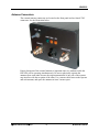
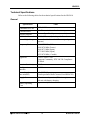
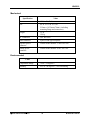
1
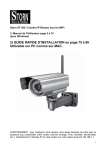
HN-2010
Repeater
User’s Guide
5375 Oakbrook Parkway
Norcross, Georgia 30093
www.cirronet.com
+1 678 684-2000
Important Regulatory Information
Cirronet Product FCC ID: HSW-2410
IC 4492A-2410
Note: This unit has been tested and found to comply with the limits for a Class A digital device, pursuant to
part 15 of the FCC Rules. These limits are designed to provide reasonable protection against harmful
interference when the equipment is operated in a commercial environment. This equipment generates,
uses, and can radiate radio frequency energy and, if not installed and used in accordance with the
instruction manual, may cause harmful interference to radio communications. Operation of this equipment
in a residential area is likely to cause harmful interference in which case the user will be required to correct
the interference at their expense.
FCC s MPE Requirements
Information to user/installer regarding FCC s Maximum Permissible Exposure (MPE) limits.
Notice to users/installers using the 24 dBi parabolic dish antenna in conjunction with all Cirronet
RF products.
FCC rules limit the use of this antenna, when connected to Cirronet RF products for point-to-point
applications only. It is the responsibility of the installer to ensure that the system is prohibited from
being used in point-to-multipoint applications, omni-directional applications, and applications where there
are multiple co-located intentional radiators transmitting the same information. Any other mode of
operation using this antenna is forbidden.
Notice to users/installers using the following fixed antennas, with Cirronet RF products:
The field strength radiated by any one of these
antennas, when connected to Cirronet RF
products, may exceed FCC mandated RF
Andrews 24dBi parabolic dish
exposure limits. FCC rules require
Andrews 18dBi parabolic dish
professional installation of these antennas in
Cushcraft 15dBi Yagi,
such a way that the general public will not be
Mobile Mark 14dBi Corner Reflector,
closer than 2 m from the radiating aperture of
Mobile Mark 9dBi Corner Reflector
any of these antennas. End users of these
systems must also be informed that RF
exposure limits may be exceeded if personnel
come closer than 2 m to the apertures of any of
these antennas.
Notice to users/installers using the following mobile antennas, with Cirronet RF products:
The field strength radiated by any one of these
antennas, when connected to Cirronet RF
products, may exceed FCC mandated RF
Mobile Mark 12dBi omni-directional,
exposure limits. FCC rules require professional
Mobile Mark 9dBi omni-directional,
installation of these antennas in such a way
MaxRad 5dBi whip,
that the general public will not be closer than
Cirronet Patch antenna,
20 cm from the radiating aperture of any of
Ace 2dBi dipole,
these antennas. End users of these systems
Mobile Mark 2dBi Stub
must also be informed that RF exposure limits
may be exceeded if personnel come closer
than 20 cm to the apertures of any of these
antennas.
Declaration of Conformity
Warning! The RLAN transceiver within this device uses a band of frequencies that are not completely harmonized within the
European Community. Before using, please read the European Operation Section of the Products User’s Guide for limitations.
0889 is the identification number of RADIO FREQUENCY INVESTIGATION LTD - Ewhurst Park, Ramsdell RG26 5RQ
Basingstoke, United Kingdom – the Notified Body having performed part or all of the conformity assessment on the product.
The WIT2410 to which this declaration relates is in conformity with the essential requirements
of the R&TTE directive 1999/5/EC and complies with the following standards and/or other
normative documents:
For Interfaces
For RLAN Transceiver
EN 55022
EN 55024
EN 300 328
EN 301 489 -1, -17
EN 60950
Use Within the European Union
The WIT2410 is intended for use within the European Community States and in the following
non-European Union States: Norway & Switzerland
Use of the WIT2410 in France
When used in France, the WIT2410 can only be operated with the France hopping pattern
selected. This is accomplished by setting the pe parameter to 1. Refer to European Union
Settings in this manual for details.
Canadian Department of Communications Industry Canada (IC) Notice
Canadian Department of Communications Industry Canada (IC) Notice
This apparatus complies with Health Canada’s Safety Code 6 / IC RSS 102.
"To prevent radio interference to the licensed service, this device is intended to be operated
indoors and away from windows to provide maximum shielding. Equipment (or its transmit
antenna) that is installed outdoors may be subject to licensing."
ICES-003
This digital apparatus does not exceed the Class B limits for radio noise emissions from
digital apparatus as set out in the radio interference regulations of Industry Canada.
Le présent appareil numérique n'émet pas de bruits radioélectriques dépassant les limites applicables aux appareils
numériques de Classe B prescrites dans le règlement sur le brouillage radioélectrique édicté par Industrie Canada.
Table of Contents
Overview .......................................................................................................................................1
Introduction ................................................................................................................................1
HopNet Products .......................................................................................................................1
External Antenna...................................................................................................................1
Built-In Antenna.....................................................................................................................1
Accessories...........................................................................................................................1
Design Features ........................................................................................................................2
Glossary of Terms .....................................................................................................................3
About HopNet Products ................................................................................................................4
Introduction ................................................................................................................................4
Operating Frequency .................................................................................................................4
HopNet Frequency Hopping Spread Spectrum Advantages .....................................................4
HopNet Data Integrity ................................................................................................................4
Flexible Power Management .....................................................................................................4
HN-2010 Repeater........................................................................................................................5
Introduction ................................................................................................................................5
Design Features ........................................................................................................................5
Antenna and Power Connections ..............................................................................................6
RF Antenna Connectors ............................................................................................................6
Conxall Power Connector ..........................................................................................................6
DB-9 Connector .........................................................................................................................7
Three-Way Switch .....................................................................................................................7
LED Status.................................................................................................................................8
Power.........................................................................................................................................8
Antenna Connectors ..................................................................................................................9
Configuring the Repeater............................................................................................................10
Technical Specifications ..........................................................................................................11
General ...............................................................................................................................11
Mechanical ..........................................................................................................................12
Environmental .....................................................................................................................12
Configuring the Network .............................................................................................................13
Overview..................................................................................................................................13
Introduction .........................................................................................................................13
Five Command Types .........................................................................................................13
WinCOM .....................................................................................................................................14
Starting the program ...................................................................................................................16
Function Keys .............................................................................................................................19
WinCom Tools ............................................................................................................................20
Script Commands .......................................................................................................................22
Demonstration Procedure ...........................................................................................................25
Modem Commands .................................................................................................................26
Serial Commands ....................................................................................................................26
Set Data Rate Divisor..........................................................................................................27
Set Protocol Mode...............................................................................................................27
Network Commands ................................................................................................................28
Set Transceiver Mode .........................................................................................................28
Set Default Handle ..............................................................................................................28
Enable Global Network Mode .............................................................................................29
Set Hopping Pattern............................................................................................................29
Set Transmit Power.............................................................................................................29
Read Receive Signal Strength Indicator (RSSI) .................................................................29
Set Point-to-Point Direct Mode............................................................................................29
Set Range Optimization ......................................................................................................30
Protocol Commands ................................................................................................................31
Set Alternative Frequency Band .........................................................................................32
Set Hop Duration.................................................................................................................32
Set Minimum Data Length...................................................................................................32
Get Maximum Data Length (read only) ...............................................................................32
Set Maximum Number of Remotes (base only) ..................................................................33
Set Packet Attempts Limit ...................................................................................................33
Set Data Transmit Delay .....................................................................................................33
Set Slot Assignment Mode (base station only) ...................................................................33
Set Base Slot Size (base station only) ................................................................................34
Set ARQ Mode ....................................................................................................................34
Status Commands ...................................................................................................................35
Banner Display Disable.......................................................................................................35
Set Escape Sequence Mode...............................................................................................35
Read Factory Serial Number High, Middle and Low Bytes. ................................................36
Set Duty Cycle ....................................................................................................................36
Enable Low Power Acquisition Mode..................................................................................36
Memory Commands ................................................................................................................37
Recall Factory Defaults .......................................................................................................37
Recall Memory ....................................................................................................................37
Store Memory......................................................................................................................37
Modem Command Summary...................................................................................................38
Guidelines for Installation ........................................................................................................39
Guidelines for Placing the Repeater ........................................................................................39
Typical HopNet Applications .......................................................................................................40
Introduction ..............................................................................................................................40
Point to Multipoint ....................................................................................................................40
Troubleshooting ..........................................................................................................................41
Overview..................................................................................................................................41
Introduction .........................................................................................................................41
Transceiver Requirements ..................................................................................................41
Common System Problems .....................................................................................................42
Guidelines for Reducing Interference ......................................................................................43
Introduction .........................................................................................................................43
Guidelines for Setting Up the Network ................................................................................43
Guidelines for Selecting Your Site ......................................................................................43
Guidelines for Avoiding Terrain Obstructions ..........................................................................44
Customer Support....................................................................................................................45
Introduction .........................................................................................................................45
Technical Assistance ..........................................................................................................45
Factory Repairs...................................................................................................................45
Warranty .....................................................................................................................................46
HN-2010
Overview
Introduction
The HopNet 10 Series family of products provides reliable wireless connectivity for
either point-to-point or point-to-multipoint applications. The HopNet products are
built around the WIT2410 radio transceiver, which employs frequency hopping
spread spectrum technology. This technology ensures:
•
Maximum resistance to noise
•
Maximum resistance to multipath fading
•
Robustness in the presence of interfering signals
HopNet Products
The HopNet family of products is built with rugged enclosures compliant with IP 66
and NEMA 4X standards for outdoor and harsh industrial environments. All Hopnet
products work with each other and can be mixed and matched in a single network. All
HopNet Products are WIT2410 compatible and can be used with the WIT2410 OEM
based products as well as with the SNAP2410 10Base T access point. The HopNet
family consists of the following products:
External Antenna
HN-210X Base/Remote Unit
HN-510 Indoor Base/Remote Station
HN-1010 Outdoor Base/Remote Station
HN-1510 Indoor Base/Remote Station
HN-2010 Repeater
Built-In Antenna
HN-210 Base/Remote Unit
HN-3010 Base/Remote Unit
Accessories
Antennas
Adapter
Power Supplies
© 2000- 2004 Cirronet™ Inc
1
M-2410-0011 Rev B
HN-2010
Design Features
The HopNet modems have many advanced features:
•
Employ frequency hopping technology with up to 75 channels in the 2401 to
2475 MHz frequency range
•
Support RS-232 and RS 485 interfaces (HN-210 and HN-510 are RS-232
only)
•
Support digital addressing for up to 64 networks, with 62 remotes per
network.
•
Use transparent ARQ protocol
•
Use same hardware for all supported data rates
•
Supports up to 230 Kbps asynchronous data rates
•
Full Duplex
•
Stores setup configuration in nonvolatile memory (FLASH)
•
Provide fast acquisition – less than 2 seconds is the typical time to acquire
hopping pattern
•
Use smart power management features
© 2000- 2004 Cirronet™ Inc
2
M-2410-0011 Rev B
HN-2010
Glossary of Terms
Refer to the following list of terms that may be unfamiliar to you. These terms are
used throughout this document.
Definition
Term
ARQ
Automatic Repeat Request. The operation in which the radio
will re-send the data until it is received correctly.
bps
Bits-per-second. A measure of information transfer rate of
digital data across a channel.
Decibel
A measure of the ratio between two signal levels. Used to
express either loss or gain.
dBi
Decibels referenced to an ideal isotropic radiator in free space.
Used to express antenna gain.
dBm
Decibels referenced to 1 milliwatt. An absolute unit used to
measure signal power. Transmitter power output or received
signal strength.
DCE
Data Communications Equipment. A device that receives data in
the form of digital signals at its input. The modem side of a
computer-to-modem connection.
DCD
Data Carrier Detect.
DTE
Data Terminal Equipment. A device that provides data in the
form of digital signals at its output. The computer side of a
computer-to-modem connection.
EIRP
Effective Isotropic Radiated Power.
ISM
Industrial, Scientific, or Medical band operating at 2.4 GHz.
Allows use of a radio without a license, but the equipment must
be immune to interference from other users in the band and
approved for use in the intended country.
Latency
The delay between when data is received on TX until it is output
on RX.
RMA
Return Material Authorization.
RTU
Remote Terminal Unit. A device used in data collection.
TDMA
Time Division Multi Access. A time slot multiplexing protocol
for multinode networking.
© 2000- 2004 Cirronet™ Inc
3
M-2410-0011 Rev B
HN-2010
About HopNet Products
Introduction
This section provides operational information about the HopNet products.
Operating Frequency
The HopNet family operates in the 2.4 GHz ISM band that allows for license-free use
and worldwide compliance.
HopNet Frequency Hopping Spread Spectrum Advantages
In the frequency domain, a multipath fade can be described as a frequency selective
notch that shifts in location and depth over time. Multipath fades typically occupy
five percent of the band. A conventional radio system typically has a five percent
chance of signal impairment at any given time due to multipath fading.
Frequency Hopping Spread Spectrum reduces the vulnerability of a radio system to
interference from jammers and multipath fading by distributing or spreading the
signal over a larger region of the frequency band.
The fade resistant, HopNet frequency-hopping technology employs up to 75 channels
and switches channels over 100 times a second to achieve high reliability throughput.
HopNet Data Integrity
An on-board 3 KB buffer and error correcting over-the-air protocol ensure data
integrity even in the presence of weak signals or jammers. The serial interface
handles both data and control of asynchronous data rates of up to 230 Kbps.
Flexible Power Management
You can set the transmit power at 10 milliwatts or 100 milliwatts. Reduced power can
reduce the size of the coverage zone, which may be desirable for multiple network
indoor applications. You can also place the transceiver module in a power-save mode,
which enables smart power management. Smart power management allows a remote
unit to drop into a lower current standby mode during transmission or receiving gaps.
This feature also allows Hopnet products to be used in various countries where the
output power requirements may vary due to regulation.
© 2000- 2004 Cirronet™ Inc
4
M-2410-0011 Rev B
HN-2010
HN-2010 Repeater
Introduction
The HopNet Repeater (HN-2010) provides extended range capability between two
HopNet networks. This repeater capability allows HopNet networks to be “daisychained” in series to send and receive data from remote locations that would
otherwise be outside the coverage area of a single network.
If a remote unit is unable to communicate with the Base because of distance or
obstruction, you can install a repeater. Repeaters work by re-transmitting the data
from the outlying remote to the base and vice versa. The repeater will introduce a
small amount of transmission delay. However, as a dual modem repeater, the HN2010 does not halve the data throughput which is common in store -n- forward
repeaters.
Design Features
The HopNet Repeater consists of the following:
•
Two modems. One for communicating with out-of-range units. The other retransmits to the base.
•
A backup battery supply (with built-in charging circuitry)
All components of the repeater are located inside a rugged, NEMA 4X weatherproof,
aluminum enclosure. Connections into and out of the box have been kept to a
minimum to reduce the chances of industrial agents getting inside the unit. The
enclosure is weatherproof and will resist the normal grime associated with industrial
environments.
© 2000- 2004 Cirronet™ Inc
5
M-2410-0011 Rev B
HN-2010
Antenna and Power Connections
There are three external connections going into the repeater enclosure and one
internal connection:
•
Two RF ports
•
A 2-pin Conxall power connector
•
An internal DB-9 connector
RF Antenna Connectors
The two RF antenna connectors are standard female TNC. These ports connect to the
output of each internal modem. You can attach remote antenna cables to these
connectors.
Conxall Power Connector
The Conxall power connector is waterproof and specifically engineered for industrial
use. This connector supplies 9 VDC nominal operating power to the HN-2010
Repeater. The view below is looking at the connector on the front of the HN-2010.
1 Ground
2 VCC
© 2000- 2004 Cirronet™ Inc
6
M-2410-0011 Rev B
HN-2010
DB-9 Connector
The DB-9 connector is located inside the back panel of the enclosure and is used to
configure the HN-2010. See the illustration below for the pin-out of the DB-9
connector.
Three-Way Switch
A miniature 3-way switch is located inside the back panel of the enclosure. See the
illustration below.
Use this switch to select one of three functions for the repeater:
•
Remote configuration
•
Base configuration
•
Repeater operation (normal setting)
When you select Base or Remote configuration mode, you can program either side of
the repeater through the DB-9 connector.
When you select repeater mode, the RX and TX data lines between the modems are
tied together so that data is passed back and forth between the remote unit and the
base unit.
© 2000- 2004 Cirronet™ Inc
7
M-2410-0011 Rev B
HN-2010
LED Status
Three external LEDs are on the front panel to inform you of the status of the repeater.
The following illustration shows the three LEDs.
Refer to the following table for a description of the LEDs.
Name
Color
Description
PWR
Green
Continuous DC power is applied
RXD
Amber
Received Data of base unit
CD
Amber
Data Carrier Detect of remote unit
An additional LED is installed inside the unit to help you configure the transceivers.
The internal LED indicates whether the transceiver is in Remote configuration, Base
configuration, or Repeater mode. This visual indication is redundant and is included
for convenience. The switch positions are also marked on the circuit board to show
their function.
Power
Power for the repeater is +7.5 to +24 VDC. The current consumption of the repeater
depends on the radio operating mode and the state of battery charge, but is typically
330 mA.
Battery backup is provided to maintain power during outages. Approximate operating
time from this battery is 2 hours. A trickle charge is maintained on the battery
whenever the unit is externally powered. Sealed lead acid cells are used in the
repeater because of their long-term reliability and charge storage characteristics.
However, the batteries will discharge if the unit is not operated for a period of time.
Voltage limiting circuits are in place at the connector to ensure that incoming voltage
does not exceed +25 VDC. One-amp polyfuses are placed in series with the external
power supply and battery to avoid catastrophic current draw in case of an accidental
short. In addition, a low voltage lockout circuit is also included to shut off the unit
when the voltage-supplied drops lower than 5.5 volts at the connector.
© 2000- 2004 Cirronet™ Inc
8
M-2410-0011 Rev B
HN-2010
Antenna Connectors
The external antenna connectors are located on the front panel and are female TNC
connectors. See the illustration below.
Proper placement of the external antenna is important since two modems inside the
HN-2010 will be operating simultaneously. Be sure to physically separate the
antennas from each other because the output transmission of one side of the repeater
may interfere with the reception of the other. Use a remote cable between the repeater
and each antenna, and space the antennas at least 2 meters apart.
© 2000- 2004 Cirronet™ Inc
9
M-2410-0011 Rev B
HN-2010
Configuring the Repeater
Complete these steps to configure the HN-2010 Repeater to the desired mode:
1. Remove the back panel of the repeater to set the function. Once the panel is
removed, you should see the following:
•
A DB-9 connector
•
A 3-way switch
•
An LED
2. Check the bicolor LED that is directly behind the switch to be sure that it
indicates which configuration mode has been selected and which unit is being
configured. The LED indicator works with the 3-way switch as follows:
3. The red LED will be on when you configure the Base modem
4. The green LED will be on when you configure the Remote modem
5. Neither LED will be on when you select repeater operation
6. Flip the 3-way switch to the Remote position and configure that modem as a
remote unit. Refer to Configuring the Network for details.
7. Flip the 3-way switch to the Base position and configure the other modem as a
base unit. Be sure the red LED is on. Refer to Configuring the Network for
details.
8. Once both modems have been configured correctly for repeater mode, set the
3-way switch back to repeater function and the unit should be ready to operate
in repeater mode.
9. Verify that the configuration LED is off; then, replace the back panel.
Note: The remote side of the repeater and the base unit with which it is communicating
must have the same network number. The base side of the repeater and the remote units
must also have the same network number and this network number should be different
from that used on the remote side. Additionally, the hop duration used on the remote side
of the repeater must differ from that used on the base side by at least +/- 5 counts of ph
(347 µsec).
© 2000- 2004 Cirronet™ Inc
10
M-2410-0011 Rev B
HN-2010
Technical Specifications
Refer to the following tables for the technical specifications for the HN-2010.
General
Specification
Value
Transmitter FCC ID
HSW-2410M
Transmit Power
+18 dBm nominal out of each antenna port
Hopping Patterns
User configurable, 64 patterns (networks) available
Number of Channels
75 US; 25 France, Spain, Japan & Canada
Line-of-Sight Range
Greater than 5 miles with 9 dB omni (per leg of
repeater)
Frequency Band
2401-2475 MHz (USA)
2448-2478 MHz (France)
2448-2473 MHz (Spain)
2473-2495 MHz (Japan)
2452-2478 MHz ( Canada)
Approvals
US FCC: Part 15. 203
European Community: ETS 300.328 Compliance
CE Mark
Receiver Sensitivity
-93 dBm
Configuration
Interface
RS-232
Power Supply
(not included)
7.5 - 24VDC Operating
(Can be purchased from Cirronet, Part #HNACPS)
Supply Current
350 mA normal operation (750 mA surge)
500 mA with battery charging
Battery Operating
Time
Approximately 2 hours
© 2000- 2004 Cirronet™ Inc
11
M-2410-0011 Rev B
HN-2010
Mechanical
Specification
Value
Case
•
NEMA 4X, IP 66
Size
•
•
8.4 in. x 5.65 in. x 3.0 in.
213mm x 143.5mm x76mm (including
mounting flange and connectors)
Weight
•
•
3.5 lb
1588 g
RF Connectors
•
TNC RF Jacks
Data Connector
•
9-pin, D-Sub type receptacle
Repeater power
connector
•
Conxall model number 1728822PG-300
Mating power
connector
•
Conxall model number 16282-2SG3XX
Temperature Range
•
-30 to +70 degrees C
Humidity
•
95% at +40 degrees C, Non condensing
Environmental
Value
© 2000- 2004 Cirronet™ Inc
12
M-2410-0011 Rev B
HN-2010
Configuring the Network
Overview
Introduction
You can configure the HopNet network using a PC and the WinCom 24 software
provided by Cirronet, Inc. WinCom24 is a software package that runs under Windows
95/98/NT/2000/XP. This chapter provides the information you need to configure your
network.
The HN-2010 is shipped from the factory initially configured as a remote with a
9600k baud rate.
Five Command Types
The WinCom24 software enables you to configure five types of commands:
•
Serial Interface Commands
•
Network Commands
•
Protocol Commands
•
Status Commands
•
Memory Commands
© 2000- 2004 Cirronet™ Inc
13
M-2410-0011 Rev B
HN-2010
WinCOM
Provided with the developer’s kit is a configuration program designed especially for
Cirronet’s wireless industrial transceivers or WIT radios. WinCOM is located on the
Manuals and Software CD included in the developer’s kit. Install WinCOM by
navigating to the Software Tools directory on the Manuals and Software CD and
double-click on wincom2.1.exe follow the installation wizard. Once it has installed,
open WinCOM by double-clicking on the WinCOM icon on the desktop.
© 2000- 2004 Cirronet™ Inc
14
M-2410-0011 Rev B
HN-2010
WinCom’s menu structure is typical of Windows conventions with File, Edit,
Options, Tools and Help selections.
Under File, Save Settings (Ctrl S) saves the current
WinCom settings to the hard drive, Print (Ctrl P)
sends whatever text is in the display field to the
printer and Exit terminates the program.
Under Edit, Copy, Paste, Find (search) and Select
All perform the familiar Windows functionality in
typical fashion.
The Options menu contains the selections, Show
Comm Errors which lists any errors encountered in
the PC UART. Check Comm Ports on Bootup tells
WinCom to verify each available port and lists
them as such in the Com Port drop down field.
See the section entitled WinCom Tools for an
explanation of this drop down.
The Help menu displays the About screen which
lists the version number, hardware and software
information for the system being used.
© 2000- 2004 Cirronet™ Inc
15
M-2410-0011 Rev B
HN-2010
Starting the program
When started, WinCOM de-asserts and re-asserts the DTR line to the radio which resets
the radio causing the sign-on banner to be displayed. If the baud rate on the computer
doesn’t match the baud rate of the radio, illegible characters will be displayed. By hitting
the PgUp or PgDn key to change the baud rate, then pressing F1 twice to toggle DTR
(resets the radio) and causes a new banner to be displayed. Continue changing baud rates
in this fashion until a legible banner is displayed as shown below.
The banner indicates the radio firmware version, whether the radio is operating as a base
or a remote and the unique factory serial number of the radio module. If nothing is
displayed in the communications window of WinCOM, verify the COM port and baud
rate settings, then reset the radio (by hitting F1 twice). Cycling power to the radio also
will cause the sign on banner to be displayed unless the banner is disabled via the Banner
Display Disable command (zb0).
The COM port and baud rate can be changed using the drop down menus on the bottom
right. All the available COM ports will be listed in the menu but will have OK or N/A
designated. If another program that uses a COM port is open, that COM port will not be
available for use by WinCOM.
The boxes on the lower right of the WinCOM window provide the status of the COM
port flow control being used to communicate with the radio. Note that DCD is only
asserted by radios configured as remotes when they are linked to a base radio. Radios
configured as bases always assert DCD even if no remotes are linked. Clicking on the
DTR or RTS buttons will change the state of the respective signal line in the COM port.
The radio is normally in data mode – data that is sent to it from the PC is transmitted over
the wireless connection. When the WinCOM window is active, keys typed on the
keyboard will be sent to the radio and will be transmitted. Unless the “Echo” box is
checked the typed data will not be displayed in the WinCOM window of the sending
radio.
© 2000- 2004 Cirronet™ Inc
16
M-2410-0011 Rev B
HN-2010
To change configuration parameters, the radio must be put into configuration mode by
clicking on the Config Mode button on the WinCOM window immediately after opening
WinCOM or after cycling power to the radio. Another method is to toggle the DTR by
pressing the F1 key twice, which de-asserts then re-asserts DTR, then pressing the F3 key
(or Config Mode button).
When the radio is in configuration mode, a “>” prompt character is displayed in the
WinCom window as shown above. Configuration parameters are sent to the radio by
entering them in the WinCom window after the “>” prompt and pressing the Enter key.
If an invalid command or value is entered, the radio will respond with “Error” as shown
above Until the command to save the parameters (m>) is issued, the new parameters will
only be valid until power is cycled or DTR is toggled by pressing the F1 key twice.
New parameter values that have been issued are saved to non-volatile memory using the
“m>” command. Refer to the Memory Commands section for details on this and other
helpful memory commands.
To exit configuration mode from the WinCom screen, use the “z>” command and press
Enter as shown below.
The return to the data mode is indicated by an absence of the “>” prompt. Refer to the
Configuration Commands section below for details on all the configurable parameters.
When the radio is linked to another radio, a communications test can be run by clicking
on the Transmit button or pressing the F6 key. Whatever ASCII string is in the Transmit
String window will be transmitted as shown below.
© 2000- 2004 Cirronet™ Inc
17
M-2410-0011 Rev B
HN-2010
If the other radio is sending data, the received data will be displayed in the WinCOM
window.
If the Binary box is checked, all characters received will be displayed subject to the
limitations of Windows. For example, a carriage return will not return the cursor to the
left side of the window but the character corresponding to 0xd value of the carriage return
will be displayed. Similarly, if the Hex Mode box is checked, all characters are displayed
in hexadecimal format.
The Clear Screen button deletes all the text in the display window. The Clear CTS and
Clear DCD buttons reset the respective changes counters to zero.
After naming the file and clicking on OK, the Capture Data window opens and shows the
amount of data being received. Clicking on Done stops the loading of received data into
the file.
© 2000- 2004 Cirronet™ Inc
18
M-2410-0011 Rev B
HN-2010
Function Keys
All of the function key shortcuts are described below:
F1 — Toggles state of DTR (Sleep). State is shown in status line.
F2 — Toggles state of RTS. State is shown in status line.
F3 — Transmits “:wit2400”. Used to enter control mode.
F5 — Toggles local echo. If you are transmitting characters through one modem to
another WIT2450, this allows you to see what you are typing.
F6 — Toggles stream mode. Causes WinCOM to transmit a repeating pattern of
characters. Useful for testing.
F8 — Toggles binary mode. Displays extended ASCII and control characters. Useful
for testing.
PgUp — Sets data rate of PC serial port to next higher value. Value is displayed in
status line. Useful when WinCOM is used to change the WIT2450 interface data rate.
WinCOM can communicate at new data rate without having to exit and re-enter
WinCOM.
PgDn — Sets data rate of PC serial port to next lower value. Value is displayed in
status line.
© 2000- 2004 Cirronet™ Inc
19
M-2410-0011 Rev B
HN-2010
WinCom Tools
There are seven selections under the Tools menu. The first, Obey CTS is useful when
just a three wire connection is made between the radio and the computer. Some PCs
let the CTS input line float. If CTS is not asserted, the PC COM port will not send
data.
Note: Unchecking this selection will have the PC COM port
ignore the state of CTS and transmit data.
When WinCOM’s transmit mode is used, data is sent continuously until the user stops
it by clicking on Stop or pressing F6. If the second tool, Single Transmit, is checked,
clicking the Transmit button will send the Transmit String a single time. There is no
need to click Stop. Clicking on the Transmit button a second time will have the string
transmitted a second time.
The third allows for checking of available Comm Ports and is useful for refreshing
the list.
© 2000- 2004 Cirronet™ Inc
20
M-2410-0011 Rev B
HN-2010
The fourth, Transmit Tools allows for testing of the Transparent, WIT2410/WIT910
or WIT2411 settings. Parameters related to how the transmission will take place can
be set including Handle, Transmit Period, whether or not a Sequence Number should
be added, if the Transmission will be continuous or one time, if the data should be
sent in Hex Format and whether or not data can be received. Data is entered into the
Data field, then Data Size can be set and clicking Fill loads the data into the Transmit
Field.
The Packet Builder is an easy way to test the multipoint addressing mode of the
WIT241x radio. Since the WIT241x operates in a star configuration in multipoint
mode, only the base radio needs to address data to specific remotes. All remotes send
data back to the base and do not need to address the data to the base. To send a packet
of data to a specific remote in a multipoint network, enter the handle of the desired
remote in the Handle window. Type whatever data to be transmitted in the Data to
Transmit window. In the bottom window, you will see the entire packet being built as
the data is entered in the windows. When all the data has been entered, click on the
Transmit button to send the data.
© 2000- 2004 Cirronet™ Inc
21
M-2410-0011 Rev B
HN-2010
WinCOM has the ability to perform any function or sequence of functions WinCOM
can perform through a script file. A script file is a text file that contains one or more
commands and arguments save with a wcr filename extension. Each command is
separated by a carriage return and linefeed. Configuration commands need to have
wait periods between them. The list of commands and their definitions is below:
Script Commands
cp <arg> Selects the COM port to use
br <arg>
Selects the baud rate to use
do Asserts DTR
df De-asserts DTR
ro Asserts RTS
rf De-asserts RTS
cm Sends configuration escape sequence
oo Obey CTS/RTS
of Do not obey CTS/RTS
sc <cmd(arg)>
Send WIT910 format configuration command
wt <arg> Pause for arg milliseconds
An example script file is shown below:
br 115200
df
wt 200
do
wt 200
cm
wt 200
sc m!
© 2000- 2004 Cirronet™ Inc
22
M-2410-0011 Rev B
HN-2010
This script file sets the baud rate of the PC COM that WinCOM is using to 115,200
kbps, de-asserts DTR, waits 200 milliseconds, asserts DTR, waits 200 milliseconds,
sends the configuration mode escape sequence, waits 200 milliseconds and then sends
the m! command to the radio. What this script file does is set the PC COM port baud
rate to 115.2 kbps, puts the radio in config mode and the issues the command to
display all of the radio parameters that have been changed from factory default. Note
that this script file leaves the radio in config mode. Cycling power or toggling DTR
will return the radio to data mode.
WinCOM prompts you to select the desired .wcr file. Opening the script file causes it
to executed immediately.
The seventh tool allows the loading of a data file for transmission. Navigate to a file
then click Open and the file is transmitted immediately.
The Capture File dialog displays with a bar showing loading progression. Once the
file has finished transmitting, the Final Average Throughput and Bytes sent numbers
will be displayed.
© 2000- 2004 Cirronet™ Inc
23
M-2410-0011 Rev B
HN-2010
Finally, the eighth tool is Save to File which launches a Save As dialog that allows
any data received to be loaded into a file.
© 2000- 2004 Cirronet™ Inc
24
M-2410-0011 Rev B
HN-2010
Demonstration Procedure
The procedure below provides a quick demonstration of the WIT241x.
1. Attach a transceiver to each computer, preferably between 5' and 30' apart for
convenience.
2. Start WinCOM running on both computers If you prefer, almost any other serial
communications program such as Procomm or QModem set for 9600 bps will
also work.
3. Turn the radios on and use the function keys to set DTR and RTS to 1 (if you are
using a terminal program other than COM24, these are typically set
automatically). The radio should respond by setting both DSR and CTS to 1, and
transmit a short sign-on message including the firmware version and whether the
unit is configured as a base or remote. Watch the states of the hardware control
lines on the status bar as you do this. The DCD indicator should be lit on the base
station. After a few seconds, the remote unit will acquire the base station's signal
and also assert its DCD signal.
4. Access modem control mode for each unit. To access modem control mode, use
the F1 key to toggle DTR to 0 and back to 1 and then press the F3 key, which
sends the ":wit2400" escape sequence. If you are not using COM24, simply turn
the radio off and back on and then type ":wit2400" (must be lower case, no
backspace characters). The transceiver should echo back “>” to indicate that you
have entered modem control mode. Check the remote unit's hopping pattern by
entering "wn?" at the prompt. The remote should respond with "0", the default
setting. Check that the base station's hopping pattern matches this by entering
"wn?" at the base station.
5. Exit control mode by entering "z>". Do this for both radios. At this point, you
should be able to type characters into either radio and see them appear at the other
side. If you are using WinCOM, you can press the F6 key to transmit a repeating
test pattern.
6. For a range test, disconnect the remote station from the computer and power
supply. The DCD indicator should remain lit as long as the base station is in
range..
7. Exit COM24 by pressing the ESC key.
© 2000- 2004 Cirronet™ Inc
25
M-2410-0011 Rev B
HN-2010
Modem Commands
The HopNet is configured and controlled through a series of commands. These
commands are sent to the modem directly when the modem is in Control Mode or
when the modem is in Data Mode if the escape sequence is enabled. The command
syntax is the same for either method, a one- or two-letter command followed by one
or more parameters. The modem will respond with a two-byte message that indicates
the new modem parameter value. The commands are loosely grouped into five
different categories: Serial commands, Network commands, Protocol commands,
Status commands and Memory commands. Each command is described in detail
below. In the descriptions, brackets ([,]) are used to denote a set of optional
arguments. Vertical slashes (|) separate selections. For example, given the string
wn[?|0..3f], some legal commands are wn?, wn0, wn3 and wna. Most commands
which set a parameter also have a ? option which causes the modem to respond with
the current parameter setting, e.g., wn? Each modem command must be followed by
either a carriage return or a line feed.
Serial Commands
These commands affect the serial interface between the modem and the host. The
default settings are 9600 bps and protocol mode 0.
Command
sd[?|00..FF]
sp[?|00..14]
© 2000- 2004 Cirronet™ Inc
Description
Set Data Rate Divisor
Data Rate Divisor (hex)
1200 bps = BF
2400 bps = 5F
9600 bps = 17
14400 bps = 0F
19200 bps = 0B
28800 bps = 07
38400 bps = 05
57600 bps = 03
115200 bps = 01
230400 bps = 00
Set Protocol Mode
00
= point-to-point transparent mode
01
= basic command and data only
02
= command, data and connection notification
04
= WIT2400 protocol mode
05 – 08 = reserved for future use
09
= mode 01 during transmit, transparent receive
0C
= mode 04 during transmit, transparent receive
0D – 10 = reserved for future use
11
= transparent transmit, mode 01 during receive
12
= transparent transmit, mode 02 during receive
14
= transparent transmit, mode 04 during receive
26
M-2410-0011 Rev B
HN-2010
Set Data Rate Divisor
Sets the serial bit rate between the modem and the host. This command takes effect
immediately and will require adjusting the host serial rate to agree. Nonstandard rates
may be programmed by entering a data rate divisor computed with the following
formula:
DIVISOR = (230400/RATE)-1
Round all non-integer values down.
Set Protocol Mode
Enables the base station to operate in a multipoint network. Depending on the user
application, more or less acknowledgment may be desired by the application.
Remotes can operate in transparent mode even though the base station is operating in
one of the nontransparent modes.
When using a protocol mode, make sure to count in packet overhead when calculating
network performance. Refer to the section on Protocol Modes for details on each
format.
© 2000- 2004 Cirronet™ Inc
27
M-2410-0011 Rev B
HN-2010
Network Commands
Network commands are used to set up a HopNet network and to set radio addressing
and configuration.
Command
wb[?|0|1]
Description
Set Transceiver Mode
0 = remote (default)
1 = base station
wd[?|1-3f] (base
only)
Set Default Handle
Used to override automatic handle assignment by the base station
30 = default
wg[?|0|1|2]
Enable Global Network Mode
0 = Link only to hop pattern specified by wn parameter (default)
1 = Link to any hop pattern, regardless of wn parameter
2 = Seamless roaming mode
wn[?|0-3f]
Set Hopping Pattern (Network Number)
0 = default
wp[?|0|1]
Set Transmit Power
0 = 10mW
1 = 100mW (default)
wr?
Read Receive Signal Strength (remote only)
wu[?|0|1]
Set Point-to-Point Direct Mode
dx[?|0-FF] (remote
only)
Set Range optimization
0 = default
Set Transceiver Mode
Sets modem operation as either base station or remote. Default is remote.
Set Default Handle
This handle will override the automatic handle assignment by the base station. When
specified for the base, the default handle determines which remote it will address
when transparent protocol mode is in effect. When 3FH is specified for the base,
broadcast mode is entered.
© 2000- 2004 Cirronet™ Inc
28
M-2410-0011 Rev B
HN-2010
Enable Global Network Mode
For networks with multiple base stations, remotes are ordinarily only able to link to
one base station, set by the hopping pattern. Mode 1 enables the global mode that
allows remotes to link to any base station they can hear, acquiring whatever hop
pattern is required. In this mode a remote can only change base stations once it is no
longer registered with a base station. Mode 2 enables seamless roaming where a
remote will seamlessly register with a new base station based on received signal
strength before it has lost registration with the old base station. To implement
seamless roaming without the potential for data loss, synchronization between base
stations is required. This feature is available in the SNAP2410 family of products
only. Bases and remotes must be set to the same mode.
Set Hopping Pattern
The HopNet has 64 preprogrammed hopping patterns (also referred to as network
numbers). By using different hopping patterns, nearby or co-located networks can
avoid interfering with each other’s transmissions. Even if both networks tried to use
the same frequency, on the next hop they would be on different frequencies.
Set Transmit Power
The HopNet has two preset transmit power levels, 10mW (10dBm) and 100mW
(20dBm). Control of the transmit power is provided through this command. Default
is 100mW.
Read Receive Signal Strength Indicator (RSSI)
This command reports the relative signal strength averaged over the last 10 hops.
This command returns a one byte value that is proportional to received signal strength
and can range from 00H to FFH. Typical values range from 30H to 80H where the
lower the number the lower the received signal strength and the higher the number the
higher the received signal strength. This is a relative indication and does not directly
correspond to a field strength number. This is available only at the remotes as the
base station is the only source that transmits on a regular basis. Plus, in a point-tomultipoint network the base will receive different signal strengths from each remote.
Set Point-to-Point Direct Mode
Sets point-to-point mode that is recommended for point-to-point applications,
especially where the remote radio is mobile and may leave and re-enter the range of
the base. This mode fixes the remote handle assignment to always be 30H and
improves the re-registration process. Must be set in both base and remote radios.
© 2000- 2004 Cirronet™ Inc
29
M-2410-0011 Rev B
HN-2010
Set Range Optimization
This command applies an adjustment factor to the over-the-air timing of remotes to
compensate for the effects of propagation delay at long ranges. The default setting of
00H is suitable for ranges of 0 to 0.8 miles (1287 m), with optimal performance at 0.1
miles (162m). Each increment of this parameter adds 0.1 miles (162 m) to the
working range. Thus the optimal and max ranges are determined by:
optimal = 0.1mi + 0.1mi x dx = 0.17km + 0.17km x dx
max = 0.8mi + 0.1mi x dx = 1.33km = 0.17km x dx
The following table presents various values of dx and the associated optimal and max
ranges.
dx
setting
range:
min
optimal
max
00H
0mi/0km
0.1mi/0.2km
0.8mi/1.3km
01H
0mi/0km
0.2mi/0.3km
0.9mi/1.5km
04H
0mi/0km
0.5mi/0.8km
1.2 mi/2.0km
06H
0.1mi/0.2km
0.7mi/1.2km
1.4mi/2.3km
09H
0.4mi/0.7km
1.0mi/1.6km
1.8 mi/3.0km
13H
1.4mi/2.3km
2.0mi/3.3km
2.8mi/4.7km
31H
4.4mi/7.3km
5.0mi/8.3km
5.8 mi/9.7km
45H
6.4mi/10.7km
7.0mi/11.7km
7.8mi/13.0km
64H
9.4mi/15.7km
10.0mi/16.7km
10.8mi/18.0km
C8H
18.8 mi/32.3km
20.0mi/33.3km
20.8mi/34.7km
FAH
24.4mi/40.7km
25.0mi/41.7km
25.8mi/43.0km
Optimal 'dx' setting for various distances.
© 2000- 2004 Cirronet™ Inc
30
M-2410-0011 Rev B
HN-2010
Protocol Commands
These commands can be used to tune the transceiver for optimum transmission of
data across the RF link. For most applications, the default values are adequate.
Command
pe[?|0-4]
Description
Set Alternative Frequency Band
0 = FCC/ETSI operation. (~2401 – 2471MHz) (default)
1 = France (~2448 – 2473MHz)
2 = Spain (~2448 – 2473MHz)
3 = Japan (~2473 – 2495MHz)
4 = Canada (~2452 – 2478MHz)
ph[?|00-fe]
(base only)
Set Hop Duration
90H = default (=10ms)
pk[?|00-d0]
Set Minimum Data Length
01 = default
pl?
Get Maximum Data Length
D4 = default (=212 bytes)
pn[?|01-3e]
(base only)
pr[?|00-ff]
Set Maximum Number of Remotes
3e = default (=62 remotes)
Set Packet Attempts Limit
10H = default
FFH = Infinite retry (RF flow control point-to-point
only)
pt[?|00-ff]
Set Data Transmit Delay
00H = default
pv[?|0|1]
Set Slot Assignment Mode
0 = default (dynamic slot assignment)
(base only)
pw[?|00-34]
(base only)
px[?|0|1]
1 = static slot assignment
Set Base Slot Size
08H = default (=32 bytes)
Set ARQ mode.
0 = ARQ enabled (default)
1 = ARQ disabled (redundant transmission)
Note: Incorrect setting of these parameters may result in reduced throughput or loss of data
packets.
© 2000- 2004 Cirronet™ Inc
31
M-2410-0011 Rev B
HN-2010
Set Alternative Frequency Band
When set to 1, limits the operating RF channel set to the 2448 to 2473MHz
frequency band for compliance with French regulatory standards. When set to 2, sets
appropriate operation for Spain. When set to 3, sets appropriate operation for Japan.
This setting should be set to 0, for FCC-compliant operation in the US (this is the
default). For Canadian operation, set this parameter to 4.
Set Hop Duration
Sets the length of time the transceiver spends on each frequency channel. A smaller
value will allow the remote to lock on to the base signal faster at system startup, and
will generally decrease packet latency. A larger value increases network capacity,
due to decreased overhead in channel switching. The hop duration is specified in
69.4µs increments. The default value of 90H corresponds to a duration of 10ms. The
maximum value of FEH is 17.627ms. For best results, do not specify a duration of
less than 3 ms. This value only needs to be set in the base which broadcasts the
parameter to all remotes. However, link time can be reduced if this value is also
programmed into the remotes, which use it as a starting value when scanning for the
base.
Set Minimum Data Length
This sets the minimum threshold number of bytes required to form a packet in
transparent mode. The radio will wait until the data transmit delay elapses before
sending a data packet with less than this number of bytes. Can be used to keep short,
intermittent transmissions contiguous. In packet modes, the length parameter in the
data packet will override this value (See Section 3.1). This value is subject to the
maximum data length even in packet mode. See Get Maximum Data Length below.
Get Maximum Data Length (read only)
This parameter indicates the largest number of bytes that a remote will transmit per
hop, based on the size of the slot it has been allocated by the base. In general more
remotes mean less data can be transmitted per remote. By reading this parameter and
dividing by the hop duration, the remote's data rate capacity can be determined.
Attempting to send protocol mode packets longer than maximum data length will
result in the packet being discarded without being sent. See Section 2.3.3 on the
tradeoffs between hop duration and data length.
© 2000- 2004 Cirronet™ Inc
32
M-2410-0011 Rev B
HN-2010
Set Maximum Number of Remotes (base only)
This parameter limits the number of remotes that can register with a given base. The
default is 62 remotes which is the maximum number of remotes that can be registered
with a base at one time. This command is useful when used in conjunction with
global roaming for load balancing when base stations are collocated. It is also useful
to assure a minimum remote throughput.
Set Packet Attempts Limit
If ARQ Mode is set to 0, sets the number of times the radio will attempt to send an
unsuccessful transmission before discarding it. If ARQ Mode is set to 1, it is the
number of times every transmission will be sent, regardless of success or failure of a
given attempt. When this parameter is set to FFH, RF flow control mode is entered
for transmissions from the radio (See Section 2.3.4). This mode can be entered for
one or both radios in a point-to-point system. Using this mode in a point-to-multipoint
system will stop transmissions to all radios when any one radio has a full buffer.
Set Data Transmit Delay
When used in conjunction with the minimum data length parameter, this sets the
amount of time from the receipt of a first byte of data from the host until the radio
will transmit in transparent mode. Default is 00H which causes transmission to occur
without any delay. When a host is sending a group of data that needs to be sent
together, setting this parameter will provide time for the group of data to be sent by
the host before the radio transmits. If the length of data to be sent together is longer
than the time slot can send, the data will not be sent together but will be broken up
over multiple hops. The length of time the radio will wait is equal to the specified
value times the hop duration.
Set Slot Assignment Mode (base station only)
Sets whether the base station will assign remote transmit slots dynamically, based on
the number of remotes currently registered or whether the base station will assign
remote transmit slots statically, based on the maximum number of remotes parameter.
If static slot assignment is selected, make sure maximum number of remotes is
correctly set. Otherwise remote transmit performance will suffer as transmit time will
be reserved for remotes that may not exist. The dynamic assignment mode will
generally be preferred; however, the static assignment mode will result in a static
maximum data length parameter.
© 2000- 2004 Cirronet™ Inc
33
M-2410-0011 Rev B
HN-2010
Set Base Slot Size (base station only)
Sets the amount of time allocated for transmission on each hop for the base station
time slot in 69.4µs increments, corresponding to 4 bytes per unit. Maximum value is
34H which corresponds to 208 bytes. If using a protocol mode, attempting to send a
packet with a length longer than this setting will cause the packet to be discarded.
Set ARQ Mode
Sets ARQ mode when set to 0 which is the default. In this mode the radio will resend
an unsuccessful transmission until either successful or packet attempt limit attempts
have been made. When set to 1 selects redundant transmit mode that will send every
transmission packet attempt limit times regardless of success or failure of any given
attempt. When redundant transmit mode is used, receiving radios will discard all
subsequent retransmissions once the transmission has been successfully received.
Thus the receiving host will receive just one copy of the transmission.
© 2000- 2004 Cirronet™ Inc
34
M-2410-0011 Rev B
HN-2010
Status Commands
These commands deal with general interface aspects of the operation of the HopNet.
Command
Description
zb[?|0|1]
Banner Display Disable
0 = disabled
1 = enabled (default)
zc[?|0..2]
Set Escape Sequence Mode
0 = disabled
1 = once after reset (default)
2 = unlimited times
zh?
Read factory serial number high byte.
zm?
Read factory serial number middle byte.
zl?
Read factory serial number low byte.
zp[?|0-5]
Set the duty cycle at which the modem will wake up to send and
receive data. Duty cycle equals 1/2N where the argument of the
command equals N.
(base only)
zq[?|0|1]
(remote only)
z>
Low Power Acquisition Mode Enable
0 = Disabled (default)
1 = Enabled
Exit Modem Control Mode
Banner Display Disable
Enables or disables display of the banner string and revision code automatically at
power-up. May be disabled to avoid being mistaken for data by the host.
Set Escape Sequence Mode
Enables or disables the ability to use the in-data-stream escape sequence method of
accessing Control Mode by transmitting the string ":wit2410". When this mode is set
to 1, the escape sequence only works immediately after reset (this is the default).
When set to 2, the escape sequence may be used at any time in the data stream when
preceded by a pause of 20 ms. For backwards compatibility with the WIT2400, the
string ":wit2400" is also accepted for entering Control Mode. Note that the escape
sequence must be interpreted as data by the radio until the last character is received,
and as such will be transmitted to a receiving radio station.
© 2000- 2004 Cirronet™ Inc
35
M-2410-0011 Rev B
HN-2010
Read Factory Serial Number High, Middle and Low Bytes.
These read only commands return one of the three bytes of the unique factory-set
serial number, which are also visible in the startup banner.
Set Duty Cycle
Allows reduced power consumption by having a remote wake up only every 2N hops
to receive and transmit. Power consumption is roughly proportional to the duty cycle
selected. For example, if N=2, the remote will wake up every fourth hop. Power
consumption will be roughly ¼ the consumption as when N=0. This parameter must
be set to the appropriate value when more than 16 remotes are in use.
Enable Low Power Acquisition Mode
When a remote is searching for a base to acquire and register with, it scans the
frequency band very rapidly. This mode consumes about 80mA of current during this
mode. To reduce the frequency consumption when a remote is in acquisition mode, a
low power acquisition mode is provided. In this mode, the remote only scans the
frequency band every other hop. This will reduce the average current consumption
during acquisition to about 40mA. The tradeoff is it can take twice as long to acquire
and register with a base, or up to 4 seconds.
© 2000- 2004 Cirronet™ Inc
36
M-2410-0011 Rev B
HN-2010
Memory Commands
The user is able to store a configuration in nonvolatile memory, which is loaded
during the initialization period every time the radio is powered up. Note that changes
to the serial port baud rate- from recalling the factory defaults or recalling memory will not take effect until DTR is toggled or power to the radio is cycled.
Command
Description
m0
Recall Factory Defaults
m<
Recall Memory
m>
Store Memory
Recall Factory Defaults
Resets the HopNet to its factory default state. This is useful for testing purposes or if
there is a problem in operation of the system and the configuration is suspect. Use
the Store Memory command afterwards if you wish the factory default settings to be
remembered the next time you cycle power or reset the radio.
Recall Memory
Useful for restoring the power-on settings after experimenting with temporary
changes to data rate, protocol or network parameters, etc.
Store Memory
This command is necessary after any command to change the data rate, transceiver
address, or other radio setting that you wish to make permanent.
© 2000- 2004 Cirronet™ Inc
37
M-2410-0011 Rev B
HN-2010
Modem Command Summary
Serial Commands
sd[?|00..ff]
sp[?|00..14]
Set Data Rate Divisor
Set Protocol Mode
Network Commands
wb[?|0|1]
wd[?|1..3f]
wn[?|00..3f]
wg[?|0|1|2]
wp[?|0|1]
wr?
wu[?|0|1]
dx[?|0..62]
Set Transceiver Mode
Set Default Handle
Set Hopping Pattern
Enable Global Network Modes
Set Transmit Power
Read Receive Signal Strength (remote only)
Set Point-to-Point Direct Mode
Set Range Optimization (remote only)
Protocol Commands
pe[?|0..4]
ph[?|00..fe]
pl?
pn[?|01..3e]
pk[?|00..d4]
pr[?|00..ff]
pt[?|00..ff]
pv[?|0|1]
pw[?|00..40]
px[?|0|1]
Set Alternative Frequency Band
Set Hop Duration (base only)
Get Maximum Data Length
Set Maximum Number of Remotes (base only)
Set Minimum Data Length
Set Packet Attempts Limit
Set Data Transmit Delay (remote only)
Set Slot Assignment Mode (base only)
Set Base Slot Size (base only)
Set ARQ Mode
Status Commands
zb[?|0|1]
zc[?|0..2]
zh?
zm?
zl?
zp[?|0..4]
zq[?|0|1]
z>
Banner Display Disable
Set Escape Sequence Mode
Read Factory Serial Number High Byte
Read Factory Serial Number Middle Byte
Read Factory Serial Number Low Byte
Set Duty Cycle(base only)
Enable Low Power Acquisition (remote only)
Exit Modem Control Mode
Memory Commands
m0
m<
m>
Recall Factory Defaults
Recall Memory
Store Memory
© 2000- 2004 Cirronet™ Inc
38
M-2410-0011 Rev B
HN-2010
Guidelines for Installation
When installing your system, always consider the following points:
•
Directional antennas are best for remote unit sites. They may increase the cost,
but they confine the transmission path to a narrow lobe and minimize the
interference from nearby stations.
•
For systems with constant interference present, you may need to change the
polarity of the antenna system and reduce data streams. Groups of short data
streams are more reliable and have a better chance of success in the presence
of interference than do long streams.
•
Systems installed in rural areas are least likely to encounter urban
interference.
•
Multiple HopNet systems can operate in close proximity to each other but
require a unique network address.
•
Poor quality coaxial cables will seriously degrade system performance. Use
low- loss cable that is suitable for 2.4 GHz operation.
•
Short cable runs minimize signal loss.
Guidelines for Placing the Repeater
Follow these guidelines for placing the repeater:
•
Be sure to carefully select the geographical location of the repeater station. A
site must be chosen that allows good communication with both base station
and remote site. This is often on top of a hill, building, or at a firewall for
indoor applications.
•
Be sure to install two antennas at the repeater station⎯one for each
transceiver. Be sure to take precautions to minimize the chance of
interference between these antennas.
•
Employ vertical separation to prevent interference with repeater antennas. In
this arrangement, mount one antenna directly over the other separated by at
least 4 feet.
© 2000- 2004 Cirronet™ Inc
39
M-2410-0011 Rev B
HN-2010
Typical HopNet Applications
Introduction
The illustration below shows a complete network of multiple data sources connected
to a central base. Units that are out of range are connected through a repeater. See the
illustration of a point-to-point application on the next page.
Point to Multipoint
This common application consists of a central host and remote terminal units or other
data collection devices. The automatic repeat requests (ARQ) and acknowledgments
inside the radio are transparent to the computer system.
© 2000- 2004 Cirronet™ Inc
40
M-2410-0011 Rev B
HN-2010
Troubleshooting
Overview
Introduction
Troubleshooting the HopNet products is not difficult, but it does require a logical
approach. It is best to begin troubleshooting at the base station because the rest of the
system synchronizes to it. If the base station has problems, the entire network will be
compromised.
This chapter provides troubleshooting information for your HopNet products.
Transceiver Requirements
For proper operation, all transceivers in the network must meet these basic
requirements:
•
Adequate and stable power
•
Secure connections ( Power, RF, and Data)
•
Proper programming especially Hop Duration and Network Address
© 2000- 2004 Cirronet™ Inc
41
M-2410-0011 Rev B
HN-2010
Common System Problems
The following table offers suggestions for resolving some common system problems
that the operator may experience from the radio system. If problems persist, contact
the factory for further assistance.
Problem
System Checks
Unit is inoperative
1. Check for proper DC voltage at the power
connector.
2. Momentarily remove and reapply power.
No Carrier Detect at
remote units or
intermittent
1. Check for secure interface connections at the
transceiver.
2. Check antenna, feedline, connectors, and reflective
power.
3. If remote unit is in synchronization but
performance is poor, it may indicate antenna
problems. Check for properly aligned antenna
headings.
4. Verify proper programming of the system
parameters.
Interference is
suspected
1. Verify that the system has a unique network
address. Nearby systems with same address will
cause interference problems.
2. If Omni-directional antennas are used with the
remote units, consider using a directional type
instead. This will often limit interference to and
from other stations.
3. Check RSSI value at the remote. A low value
would correspond to weak signal strength.
© 2000- 2004 Cirronet™ Inc
42
M-2410-0011 Rev B
HN-2010
Guidelines for Reducing Interference
Introduction
The transceivers share the same frequency spectrum with other services and other
Part 15 devices in the US. Because of this, you may not achieve 100 percent error free
communications in a given location. You should also expect some level of
interference. However, the flexible design of the radio and the hopping pattern should
allow for adequate performance as long as care is taken in choosing station location,
configuration parameters of the transceivers, and protocols techniques.
Use the following guidelines to reduce interference in your HopNet system.
Guidelines for Setting Up the Network
In general, the following points should be followed when setting up a network:
•
Systems installed in rural areas are least likely to encounter interference.
•
If possible, use directional antennas at remote sites. The directional antennas
confine the transmission path and reception pattern to a comparatively narrow
lobe, which minimizes interference from stations located outside the pattern.
•
Multiple HopNet systems can co-exist in close proximity to each other with
very minor interface as long as they are assigned a unique network address.
Each network address has a different hop pattern.
•
If interference is suspected from a similar operating system, change the
antenna polarization. This will provide an additional 20dB of attenuation to
interference.
•
For indoor applications, set all transceivers for the lowest level necessary for
reliable communications. This lessens the chance of interference from nearby
systems.
Guidelines for Selecting Your Site
Use these guidelines to select a proper site for the master remote stations. Suitable
sites must provide the following:
•
An adequate and stable source of primary power.
•
Antenna location that provides an unobstructed transmission path in the
direction of the associated units.
•
Proper antenna selection, data access, and feedline cabling
•
A clear line-of-sight. Microwave radio signals travel primarily by line-ofsight, and obstructions between the sending and receiving stations will affect
system performance.
© 2000- 2004 Cirronet™ Inc
43
M-2410-0011 Rev B
HN-2010
Guidelines for Avoiding Terrain Obstructions
The HopNet transceivers operate in the 2.4 GHz frequency band. While this band
offers many advantages over the VHF band for data transmission, it is also more
prone to signal attenuation from obstructions such as terrain, foliage, buildings and
anything else in the transmission path.
Use the following guidelines to avoid terrain obstructions:
•
A line-of-sight transmission path between the base and the associated remote
sites provides for the most reliable transmission path.
•
A line-of-sight path can be achieved by mounting the station antenna on a
tower or elevated structure that raises it to a sufficient level to clear
surrounding terrain and other obstructions.
•
The importance of a clear transmission path relates closely to the distance to
be covered. If the system is to cover only a limited geographical area such as
1-3 miles, then some obstructions may be tolerated with minimal impact.
•
For longer-range systems, any substantial obstruction in the transmission path
could compromise the performance of the system.
© 2000- 2004 Cirronet™ Inc
44
M-2410-0011 Rev B
HN-2010
Customer Support
Introduction
Cirronet, Inc. products are designed for long life and trouble free operation. The
following information is provided if servicing becomes necessary.
Technical Assistance
Technical assistance for Cirronet products is available during the hours of 9:00 A.M –
5:30 P.M. Eastern Standard Time. When calling, please have available the complete
model name, serial number, and a complete description of the problem. Most
problems can be resolved without returning the unit to the factory.
The following telephone numbers are available for assistance.
Phone
678-684-2000
Fax
678-684-2001
Factory Repairs
If return of equipment is necessary, you will be issued a Return Material
Authorization number (RMA #). The RMA # will help expedite the repair so that
equipment can be returned as quickly as possible. Please be sure to include the
RMA number (#) on the outside of the shipping box and on any correspondence
relating to the repair. Any equipment returned without an RMA # may be delayed in
the repair cycle.
Please be sure to carefully package all items to be returned and address to:
CIRRONET, INC.
5375 Oakbrook Parkway
Norcross, GA 30093
RMA # ***
© 2000- 2004 Cirronet™ Inc
45
M-2410-0011 Rev B
HN-2010
Warranty
Seller warrants solely to Buyer that the goods delivered hereunder shall be free from defects in
materials and workmanship, when given normal, proper and intended usage, for twelve (12)
months from the date of delivery to Buyer. Seller agrees to repair or replace at its option and
without cost to Buyer all defective goods sold hereunder, provided that Buyer has given Seller
written notice of such warranty claim within such warranty period. All goods returned to Seller
for repair or replacement must be sent freight prepaid to Seller’s plant, provided that Buyer first
obtain from Seller a Return Goods Authorization before any such return. Seller shall have no
obligation to make repairs or replacements which are required by normal wear and tear, or which
result, in whole or in part, from catastrophe, fault or negligence of Buyer, or from improper or
unauthorized use of the goods, or use of the goods in a manner for which they are not designed,
or by causes external to the goods such as, but not limited to, power failure. No suit or action
shall be brought against Seller more than twelve (12) months after the related cause of action has
occurred. Buyer has not relied and shall not rely on any oral representation regarding the goods
sold hereunder, and any oral representation shall not bind Seller and shall not be a part of any
warranty.
THE PROVISIONS OF THE FOREGOING WARRANTY ARE IN LIEU OF ANY
OTHER WARRANTY, WHETHER EXPRESS OR IMPLIED, WRITTEN OR ORAL
(INCLUDING ANY WARRANTY OR MERCHANT ABILITY OR FITNESS FOR A
PARTICULAR PURPOSE). SELLER’S LIABILITY ARISING OUT OF THE
MANUFACTURE, SALE OR SUPPLYING OF THE GOODS OR THEIR USE OR
DISPOSITION, WHETHER BASED UPON WARRANTY, CONTRACT, TORT OR
OTHERWISE, SHALL NOT EXCEED THE ACTUAL PURCHASE PRICE PAID BY
BUYER FOR THE GOODS. IN NO EVENT SHALL SELLER BE LIABLE TO BUYER
OR ANY OTHER PERSON OR ENTITY FOR SPECIAL, INCIDENTAL OR
CONSEQUENTIAL DAMAGES, INCLUDING, BUT NOT LIMITED TO, LOSS OF
PROFITS, LOSS OF DATA OR LOSS OF USE DAMAGES ARISING OUT OF THE
MANUFACTURE, SALE OR SUPPLYING OF THE GOODS. THE FOREGOING
WARRANTY EXTENDS TO BUYER ONLY AND SHALL NOT BE APPLICABLE TO
ANY OTHER PERSON OR ENTITY INCLUDING, WITHOUT LIMITATION,
CUSTOMERS OF BUYERS.
© 2000- 2004 Cirronet™ Inc
46
M-2410-0011 Rev B