1
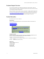
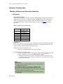
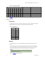
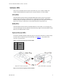
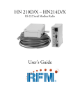
Xtreme/104 Radio Modems PC/104 Card Manual Xtreme/104 900 MHz and 2.4 GHz Radio Modems PC/104 Interface User’s Manual Contact Information: Connect Tech Inc. 42 Arrow Road Guelph, Ontario, Canada N1K 1S6 Tel: 519-836-1291 (International) 800-426-8979 (Canada & USA) Fax: 519-836-4878 Email: [email protected] [email protected] Web: www.connecttech.com CTIM-00032 Revision 0.01 March, 2007 Xtreme/104 Radio Modem, Connect Tech Inc. One Year Warranty Connect Tech Inc. provides a One-Year Warranty for all Xtreme/104 Radio Modem products built with Cirronet modules. Should this product, in Connect Tech Inc.'s opinion, fail to be in good working order during the warranty period, Connect Tech Inc. will, at its option, repair or replace this product at no charge, provided that the product has not been subjected to abuse, misuse, accident, disaster or non Connect Tech Inc. authorized modification or repair. You may obtain warranty service by delivering this product to an authorized Connect Tech Inc. business partner or to Connect Tech Inc. along with proof of purchase. Product returned to Connect Tech Inc. must be pre-authorized by Connect Tech Inc. with an RMA (Return Material Authorization) number marked on the outside of the package and sent prepaid, insured and packaged for safe shipment. Connect Tech Inc. will return this product by prepaid ground shipment service. Should the product prove to be irreparable, Connect Tech Inc. reserves the right to substitute an equivalent product if available. The above warranty is the only warranty authorized by Connect Tech Inc. for the Xtreme/104 Radio Modems. Under no circumstances will Connect Tech Inc. be liable in any way for any damages, including any lost profits, lost savings or other incidental or consequential damages arising out of the use of, or inability to use, such product. Copyright Notice The information contained in this document is subject to change without notice. Connect Tech Inc. shall not be liable for errors contained herein or for incidental consequential damages in connection with the furnishing, performance, or use of this material. This document contains proprietary information that is protected by copyright. All rights are reserved. No part of this document may be photocopied, reproduced, or translated to another language without the prior written consent of Connect Tech, Inc. Copyright 2007 by Connect Tech, Inc. Trademark Acknowledgment Connect Tech Inc. acknowledges all trademarks, registered trademarks and/or copyrights referred to in this document as the property of their respective owners. Not listing all possible trademarks or copyright acknowledgments does not constitute a lack of acknowledgment to the rightful owners of the trademarks and copyrights mentioned in this document. 2 Revision 0.01 Xtreme/104 Radio Modem, Connect Tech Inc. Table of Contents One Year Warranty ..........................................................................................................................................2 Copyright Notice..............................................................................................................................................2 Trademark Acknowledgment...........................................................................................................................2 Table of Contents.............................................................................................................................................3 List of Figures ..........................................................................................................3 List of Tables............................................................................................................3 Customer Support Overview............................................................................................................................4 Customer Support Overview............................................................................................................................4 Contact Information .........................................................................................................................................4 Introduction......................................................................................................................................................5 Features............................................................................................................................................................5 Radio Modem Modules..............................................................................................5 Xtreme/104 Base Card ..............................................................................................5 Figure 1: Xtreme/104 Radio Modem Jumper Locations ............................................6 Hardware Installation.......................................................................................................................................6 Installing the PC/104 Radio Modem into your PC/104 Stack .........................................6 Hardware Configuration ..................................................................................................................................7 Memory Address and Interrupts Selection ...................................................................7 I/O Address ................................................................................................................7 IRQ Selection .............................................................................................................8 IRQ Mode...................................................................................................................8 Indicator LEDs.........................................................................................................9 ACQ (DCD) ...............................................................................................................9 WAK (DTR)................................................................................................................9 Optional External LEDs.............................................................................................9 Operational Setup ....................................................................................................10 Errata.......................................................................................................................11 List of Figures Figure 1: Xtreme/104 Radio Modem Jumper Locations ................................................................................ 6 List of Tables Table 1: Jumper J2-2 to J2-8 Functions......................................................................................................... 7 Table 2: J2 Jumpering Examples ................................................................................................................... 8 Revision 0.01 3 Xtreme/104 Radio Modem, Connect Tech Inc. Customer Support Overview If you experience difficulties after reading the manual and/or using the product, contact the Connect Tech reseller from which you purchased the product. In most cases the reseller can help you with product installation and difficulties. In the event that the reseller is unable to resolve your problem, our highly qualified support staff can assist you. Our support section is available 24 hours a day, 7 days a week on our website at: www.connecttech.com/sub/support/support.asp. See the contact information section below for more information on how to contact us directly. Our technical support is always free. Contact Information We offer three ways for you to contact us: Email/Internet You may contact us through the Internet. Our email and URL addresses on the Internet are: [email protected] [email protected] www.connecttech.com Note: Please go to the Download Zone or the Knowledge Database in the Support Center on the Connect Tech website for product manuals, installation guides, device driver software and technical tips. Submit your technical support questions to our customer support engineers via the Support Center on the Connect Tech website. Telephone/Facsimile Technical Support representatives are ready to answer your call Monday through Friday, from 8:30 a.m. to 5:00 p.m. Eastern Standard Time. Our numbers for calls are: Telephone: 800-426-8979 (North America only) Telephone: 519-836-1291 (Live assistance available 8:30 a.m. to 5:00 p.m. EST, Monday to Friday) Facsimile: 519-836-4878 (on-line 24 hours) Mail/Courier You may contact us by letter at: Connect Tech Inc. Technical Support 42 Arrow Road Guelph, Ontario Canada N1K 1S6 4 Revision 0.01 Xtreme/104 Radio Modem, Connect Tech Inc. Introduction Connect Tech’s PC/104 Radio Modems, available with Cirronet’s WIT910, WIT2450 or WIT2410 roaming transceiver modules, offer a conveinient, reliable method to introduce wireless communications into your PC/104 application. Fully PC/104 2.5 compliant, this card installs into an available PC/104 position in your stack to communicate up to 20 miles away (“line of sight” only), depending on model and antenna configuration. Features Radio Modem Modules • • • • • • • • • • • • Frequency hopping spread spectrum technology 900 MHz or 2.4 GHz , incorporating Cirronet’s WIT910, WIT2410 or WIT2450 frequency hopping transceiver modules Radio modem operating ranges of up to 20 miles (900 MHz model, with appropriate antennas in a “line of sight” implementation) Low power consumption (can be powered via the PC/104 bus) Store and forward repeating while operating as a node (WIT910) License-free operation Immunity to jamming and multipath fading, even in noisy environments Available with roaming capability (2.4 GHz) FCC certified Data speeds between 86.4 Kbps (900 MHz) and 230.4 Kbps (2.4 GHz) Point-to-point and point-to-multipoint network deployments Operating temperature range of 0˚C to 70˚C Xtreme/104 Base Card • • • • • Jumper selectable I/O addresses and interrupts I/O address ranges from 0x000 to 0x7F0 (jumper selectable) RTS/CTS hardware flow control Jumper selectable IRQ interrupts 3, 4, 6, 7, 9, 10, 11, 12, 14, 15 Requires no additional drivers, appears as COM port to your operating system Revision 0.01 5 Xtreme/104 Radio Modem, Connect Tech Inc. Figure 1: Xtreme/104 Radio Modem Jumper Locations Hardware Installation Installing the PC/104 Radio Modem into your PC/104 Stack Before you place your Xtreme/104 Radio Modem into your PC/104 stack, take a minute to ensure that your package includes the required components that should have shipped with your PC/104 Radio Modem. • One unit • One CD containing software and documentation • One cable (optional) • One antenna (optional) If any of these components is missing, contact Connect Tech (see Contact Details) or your reseller. This card can be installed into any PC/104 stack and is fully PC/104 2.5 compliant. 6 Revision 0.01 Xtreme/104 Radio Modem, Connect Tech Inc. Hardware Configuration Memory Address and Interrupts Selection I/O Address J2 positions 2 through 8: Jumper block J2, positions 2 through 8, define the I/O Base Address setting for the UART. The board decodes 16 consecutive I/O addresses starting at the Base address. Each of the jumper positions corresponds to one bit of the I/O Address. If a jumper is installed (“On”), then the corresponding bit equals 1, otherwise that bit equals zero. (Please see Figure 1) for jumper locations.) Table 1: Jumper J2-2 to J2-8 Functions J2 position 2 3 4 5 6 7 8 Corresponding I/O Address Bit I/O address bit 4 I/O address bit 5 I/O address bit 6 I/O address bit 7 I/O address bit 8 I/O address bit 9 I/O address bit 10 J2 position 1: Position J2-1 enables the control of the CFG (Configuration) signal on the Radio Modem. When the CFG signal is asserted, the Radio Modem is placed into its Configuration Mode. This is an alternate method of placing the Radio Modem in this state. When this position is not jumpered (“Off”): • The control of the Radio Modem CFG signal is disabled. When this position is jumpered (“On”): ● The control of the Radio Modem CFG signal is enabled, and the operation of the CFG signal is controlled by I/O writes to I/O Base Address + 0x08 [See Note 1 below]. o Writing 0x00 disables the CFG mode, writing 0x01 enables the CFG mode. Only bit-0 of the written byte has significance, all other bits are ignored. (The CFG mode is Disabled at power-up). Notes: [1] See Errata. [2] The lower 3 bits of the I/O address (A2, A1, A0), access the Registers of the UART. [3] The Base I/O Address is always on a boundary of 16, [4] The total I/O setting range possible is 0x000 to 0x7F0. . [5] Settings below 0x100 should be used with caution, since there may be conflicts with system devices. [6] Some systems may not support an I/O Base setting greater than 0x3F8. Revision 0.01 7 Xtreme/104 Radio Modem, Connect Tech Inc. Table 2: J2 Jumpering Examples 8 Off Off Off Off On Off Off 7 On On On On Off On On 6 On On On On On On On J2 Positions 5 4 Off Off Off Off Off Off Off Off Off On On On On On UART I/O Address 3 Off Off Off Off On On On 2 Off Off On On Off On On 1 Off On Off On On Off On 0x300 (01100000uuu) 0x300 (01100000uuu) 0x310 (01100010uuu) 0x310 (01100010uuu) 0x560 (10101100uuu) 0x3F0 (01111110uuu) 0x3F0 (01111110uuu) CFG I/O Address --0x308 (01100001xxx) [Note 1] --0x318 (01100011xxx) [Note 1] 0x568 (10101101xxx) [Note 1] --0x3F8 (01111111xxx) [Note 1] (Please see Figure 1 for jumper locations) Notes: [1] See Errata section IRQ Selection The IRQ number selection is controlled by jumper block J1. Jumpers 1 through 10 correspond to the IRQ numbers listed in Table 2 below. Only one jumper should be installed. Table 3: IRQ Selection J1 Position 1 2 3 4 5 6 7 8 9 10 IRQ# 3 4 6 7 9 10 11 12 14 15 IRQ Mode J2-9 (when jumpered or “On”) enables the IRQ to be shared with other cards/devices in the system. J2-10 (when jumpered or “On”) provides a 1K pull-down resistor on the selected IRQ signal. This is used in conjunction with the Shared IRQ mode. Only one 1K resistor is allowed in the system per Shared IRQ. Only one card in the system should provide this pull-down. Note: The IRQ Sharing mechanism is implemented as described in the PC/104 Bus Specification V2.5. (Please see Figure 1 for jumper locations.) 8 Revision 0.01 Xtreme/104 Radio Modem, Connect Tech Inc. Indicator LEDs There are two red LEDs located on the PC/104 board. They serve to indicate whether the Xtreme/104 Radio Modem has aquired a lock (ACQ) and whether it is awake (WAK). ACQ (DCD) This LED indicates that the Xtreme/104 Radio Modem has acquired (ACQ) a lock with the hopping pattern. This applies to modems that are configured to be Remotes. A Base Radio Modem would have this LED on at all times. The signal which drives this LED is also the DCD input on the serial port. When DCD is on, the Radio Modem has acquired the lock. WAK (DTR) This LED indicates that the Xtreme/104 Radio Modem is awake (WAK), or not sleeping. The serial port DTR signal is driving both this LED and the Sleep Signal of the Radio Modem. When DTR is on, the Radio Modem is awake. Optional External LEDs The Xtreme/104 Radio Modem includes the option to connect the LED drivers to LEDs located external to board. Connector P4 provides this ability. (See Figure 2). The pinout for this connector is provided below. Table 4: Connector P4 Pinout for External LEDs Pin 1 2 3 4 Function ACQ Gnd WAK Gnd Figure 2: P4 Connector Option for External LEDs Revision 0.01 9 Xtreme/104 Radio Modem, Connect Tech Inc. Operational Setup A minimum operational setup for the Xtreme/104 Radio Modem card must include an antenna connected to the Radio Modem module at each end of the communications link. The following illustration demonstrates a typical lab or prototype setup using two possible cable/antenna styles (only one antenna is needed at each end). The mounting surface for the antenna end of the patch cable could be the housing of the PC/104 stack or some other mounting surface. A metallic surface is preferred, but not necessary. In most situations a vertical orientation of the antenna works best, but this can be influenced by the environmental factors listed below. A field setup or a final application setup may vary greatly from application to application. Environmental factors play a big role in the effective deployment of wireless communication equipment. The following items need to be considered. • • • • • • • Desired range Obstacles between the stations (hills, buildings, trees, etc) RF power output settings of the modules Attenuation of the interconnecting RF cables RF gain of the antennas Prevailing weather conditions Multi-path (multiple RF pathways) effects In many circumstances experiments need to be conducted on the field setup to determine the effectiveness of the setup. Connect Tech’s partner, Cirronet, can offer application assistance with the choice of RF cabling and antennas and with the environmental considerations for a particular field installation. Contact Cirronet to ensure your unique application requirements are met. 10 Revision 0.01 Xtreme/104 Radio Modem, Connect Tech Inc. Errata CFG Mode Operation Problem Description Revision “B” boards exhibit a problem when using the Radio Modem CFG Signal control feature (enabled with J2-position-1). When using an I/O address of Base+0x08, the data byte written also gets transmitted by the UART. Solution: The issue will be resolved in revision “C” of the board. Resolution: Instead of using an I/O address of Base+0x08, use Base+0x0F. The data value used will also be written into the UART Scratch-Pad register, but this does not affect the normal operation of the UART. Revision 0.01 11