1
Record Submittal
Thomas Engineering
BMS
Sales Order # 130079-01
Purchase Order # 129006
TCS41704A / AHU 00407
9/25/13
Buffalo Air Handling Contact Information
Buffalo Air Handling Factory:
Buffalo Air Handling
467 Zane Snead Drive
Amherst, VA 24521
Tel: (434) 946-7455
Fax: (434) 946-0226
Subject to Terms and Conditions which are attached
467 Zane Snead Drive Amherst, VA 24521 Tel: 434-946-7455 Fax: 434-946-0226 www.buffaloair.com
#SMPP009
TERMS AND CONDITIONS OF SALE
The following are the Standard Terms and Conditions of Sale of the
Buffalo Air Handling Division of Air & Liquid Systems Corporation
(“Seller”).
1. ACCEPTANCE
OF
SELLER'S
TERMS
AND
CONDITIONS OF SALE. Seller and Buyer agree that the following
terms and conditions will apply to any order from Buyer accepted by
Seller. No order or contract will be binding on Seller unless and until
accepted, and acknowledged by Seller's office in Amherst, Virginia.
Sales representatives are not authorized to bind Seller. No terms or
conditions other than those stated herein, whether contained in Buyer's
purchase order or shipping release or elsewhere, and no written or oral
agreement that purports to vary these terms and conditions will be
binding on Seller, unless hereafter set forth in writing and signed by an
authorized officer of Seller. Buyer's assent to the terms and conditions
set forth herein will be conclusively presumed from Buyer's receipt of
this acknowledgement without prompt written objection or from
Buyer's acceptance of all or any part of the equipment or material
ordered.
2. CHANGES. Equipment changes by Buyer involving design
and/ or drawing modifications, or after approval and release for
manufacture, will result in an administrative charge, in addition to any
price adjustment for the change, and may result in a delay of the
scheduled shipping date.
3. CANCELLATION CHARGES. An order canceled prior to
shipment will be subject to cancellation charges.
4. INVOICING TERMS. Payment terms: Net 30 days, with
interest charges of 1.5% per month thereafter. All shipments will be
subject to the approval of Seller's credit department. Quotations are
subject to acceptance within 30 days from quotation date.
Seller will invoice, and payment will be due in accordance with
the payment terms above, for : a) shipment of complete order; b) partial
shipment of order; c) finished product or work in progress when any
shipment delay is caused by Buyer for any reason including, but not
limited to, change in requirements, components not received, rigging or
staging not available, site not ready, etc. Seller will be entitled to
reasonable storage charges for any such delay caused by Buyer.
5. DELIVERY. Seller will use its best efforts to deliver on a
timely basis.
Seller, however, will not guarantee or accept
consequential losses associated with its inability to meet a specific time
of day or specific date. FOB origin.
6. ESCALATION TERMS. Prices on equipment of Seller's
manufacture are firm for shipments made within 6 months from date of
purchase order; for shipments made beyond 6 months from date of
purchase order, prices are protected for 6 months from any announced
price increase occurring later than the date of the purchase order.
Beyond that period, prices will be adjusted to Seller's prices at time of
shipment with adjustment limited to 20% of the purchase order price.
Contracts providing for escalation based on an index will be escalated
from the date of purchase order to the date of shipment using 100% of
the quoted price as the base. Prices on equipment not of Seller's
manufacture are subject to adjustment to the prices in effect at the time
of shipment.
7. FORCE MAJEURE. Neither party will be liable for any
failure or delay in performance due to force majeure conditions,
including, but not limited to, war, riot or civil disturbance, accident or
equipment breakdown, strikes or disputes with employees, actions of
any governmental authority, compliance with any law order, regulation
or directive of any governmental authority, shortages of or inability to
obtain materials, supplies, transportation, fuel or energy, or any cause
beyond the reasonable control of Seller or Buyer, as the case may be.
8. TAXES. All taxes which Seller may be required to pay or collect
under any existing or future laws with respect to the sale, purchase,
delivery, storage, manufacture, processing, use, consumption or
transportation of any equipment ordered by Buyer, including taxes
upon or measured by receipts from sales (except net income and equity
franchise taxes) will be for the account of Buyer.
9.
PATENTS. If the equipment is to be manufactured in
accordance with Seller's specifications. Seller agrees to defend any
proceeding brought against Buyer on a claim that the equipment
furnished to Buyer infringes any patent in the United States and Seller
agrees to pay all direct and actual damages and costs awarded against
Buyer in any such proceeding, provided that Seller is promptly notified
in writing of any such proceeding and given authority, information and
assistance for the defense thereof. If Buyer furnishes the specifications
then Buyer shall hold Seller harmless against any such claim which
arises out of compliance with specifications.
10. NON-CONFORMANCE. Seller will replace, at the original
point of delivery, equipment or material which upon inspection before
installation is found defective or not in conformity with the applicable
specifications, provided that written notice has been given of such
defect or non-conformity within 15 days of receipt of equipment by
Buyer and Seller is given reasonable opportunity to inspect. No claims
will be accepted by Seller for the cost of any labor expended on such
equipment or material, or for any separate special indirect, incidental or
consequential damages to anyone. If Buyer does not give such notice,
the equipment or material shall be deemed to be in all respects in
accordance with the specifications.
11. BUYER'S EXCLUSIVE REMEDY; LIMITATION OF
DAMAGES. In case of an alleged breach, Seller's entire liability and
Buyer's exclusive remedy shall be as follows:
In all situations involving the performance or non-performance
of equipment, Buyer's remedy is (1) the adjustment or repair of the
equipment or, at Seller's option, the replacement of the equipment or
(2) if Seller is unable to repair the equipment or replace it with
equipment in good working order, Buyer will be entitled to a refund or
credit in the amount of purchase price paid by Buyer for the equipment.
Seller's liability for damages to Buyer for any cause whatsoever
and regardless of the form of action or claim, whether in contract or in
tort, including negligence, shall be limited to 110% of the purchase
price of the equipment or part that is the subject matter of, or directly
related to, the action or claim on which such liability is based. In no
event will Seller be liable for any lost profits, lost savings or any
special, indirect, incidental or consequential damages, even if Seller has
been advised of the possibility of such damages, or for any claim by
Buyer based on any third party claim, except as provided in the Section
entitled Patents.
12. DRAWINGS. Unless otherwise stated in the quotation, prices
include a set of customer interface contract drawings and service
manuals. If additional drawings are needed or Buyer-initiated changes
require additional drawings, they will be provided only upon receipt of
a written order authorizing additional charges for such drawings.
WARRANTY
Seller warrants for a period not in excess of 18 months from
date of shipment or 12 months from date of installation, whichever is
earlier, the design, construction and materials of Seller's products to be
free from defects in materials and workmanship. Seller's sole
obligation and Buyer's exclusive remedy under this Warranty is limited
to the repair or replacement without charge, f.o.b. Seller's factory, of
any defective parts. Seller will not be responsible for damages of any
nature, resulting from breach of the above stated Warranty or from any
defect in Seller's products, either in materials, design, or construction,
or arising from the use of such products. Seller does not guarantee
against abrasion, corrosion or erosion.
The above stated warranty constitutes the only warranty
made by Seller and is given expressly in lieu of all other warranties
express or implied, including any implied warranties of
merchantability or fitness for a particular purpose.
Warranties on equipment not of Seller's manufacture are limited
to the terms of any warranties furnished by Seller's suppliers to the
extent they may be made available to Buyer.
01/01/10
Thomas Engineering, Inc.
BMS
TCS41704A / AHU 00407
Buffalo Air Handling
SO# 130079-01
Record Submittal
Data Sheets & Drawings
Fans
Motors
Coils
Filters
Mixing
Humidifier
Dehumidifier
Calculations - Pressure Drop
Electrical & Test Procedures
1
2
3
4
5
6
7
8
9
10
1
Data Sheets
& Drawings
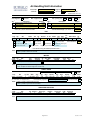
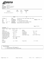
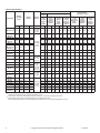
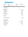
Air Handling Unit Information
Sales Order:
Job Order:
130079-01
Dwg. No.: E-13331-1
13331
Revision:
Data Sheets
C
AC2000 Data Sheets, Version 6.30
GENERAL
Customer: Thomas Engineering, Inc., Hoffman Estates, IL
End User: BMS
Engineer: Thomas Engineering, Inc. / Marty Berthold
Mark: TCS41704A/AHU00407
BB2AI-DPFHCW6DHHCNO
Qty/Size/Type: 1
2
Sales Office: 999 BAH - Home Office
Sales Rep.: Jim Adamczak
Project Mgr.: Dave Lewandowski
Designer: Ivan Johnson / Malcolm Childress
Cust. PO: 129006
UNIT CONSTRUCTION
CASING : 2" Thick w/ 3 pcf density fiberglass insulation
Roof:
Flat
Exterior:
0.063 In. Stucco Aluminum
Interior:
Bulkhead:
Design Pressure (+/-)
Environment:
18
16
Fasteners:
GA 304 Stainless Steel
GA 304 Stainless Steel
Exterior Painted:
No
Indoor
Exterior Stainless steel
12
inches W.G.
construction
Interior Stainless steel
- Entire unit
- Single wall construction
Paint Finish:
Color:
Thermal Break Construction:
Yes
Location: Entire unit
Knockdown Construction:
No
KD Type:
1
Unit Installed On : Housekeeping pad or building floor
1
Insulation Type:
Plain surfaced
BASE 2 :
C8 x 11.5 lb/ft Steel
Floor Sht.:
10
Drain Pan:
16
- Entire unit
Structural
- Entire unit except the cooling coil & humidifier sections
stitch-welded and sealed
with no turned-up perimeter lip.
GA IAQ continuously sloped 304 Stainless steel
Drain Pan Connection Hand: Right Hand
2
Polyurethane foam insul.* , 20 GA galv. steel coversheet & removable lifting lugs
GA 304 Stainless steel
Floor sheets are
- Provide level foundation under perimeter of each section.
- Cooling coil & humidifier sections
* - Base assembly meets NFPA 90A per UL723
- All black steel, including unit base, shall be painted w/ epoxy mastic.
DOORS 3 :
3
Qty:
Size:
2
1
4
24 x 36
36 x 36
18 x 36
4
Type :
Dual-seal
Dual-seal
Dual-seal
4
(Qty) Latches:
(2) 260 Ventlok
(2) 260 Ventlok
(2) 260 Ventlok
- Refer to main assembly drawing for door locations.
Dead Lights:
None
12 x 12 Thermal pane
None
- Standard construction (Single-seal type) and Thermal break construction (Dual-seal type)
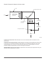
Notes: 1) BAH to provide a 2" wide flanged 304 stainless steel discharge collar (5" deep). Mechanically fasten collar to unit with
minimum 18-8 SST hardware only.
2)
3) All Interior seams to be caulked with clear FDA approved caulking. The exterior to be caulked with standard caulk.
BAH to provide an MSDS sheet for all caulking used.
4) Caulking must be kept to a minimum and not smeared beyond the seam. Caulking shall be rated for temperatures
above the maximum design temperature of the unit.
5) All doors to have a safety chain to limit door swing to 90°.
6) BAH to provide a 2" wide flanged stucco aluminum inlet collar (5" deep). Mechanically fasten collar to unit.
7) BAH to provide a C6 x 8.2 lb/ft Steel channel sub-base under the unit channel base.
Page 1 of 8
9/25/2013 1:47 PM
Air Handling Unit Information
Sales Order:
Job Order:
130079-01
Dwg. No.: E-13331-1
13331
Revision:
Data Sheets
C
AC2000 Data Sheets, Version 6.30
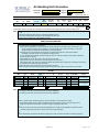
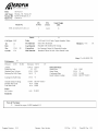
WEIGHT
Unit shipped in
3
sections.
Max. weight/section:
5
Description
Sec.
1 Inlet/Pre & interm. filter/PHC/PCC
2 Dehumidifier/Fan
3
Weight LB
1,700
2,900
RHC/RCC/Humidifier/Discharge
5
Max. opening size:
LB
Sec.*
4
5
1,800
Hx
D (In.)
Wx
Description
Weight LB
6
Total Estimated Weight (Less Water)
- Section (Sec.) listed in direction of airflow.
6,400
LB :
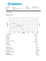
FAN
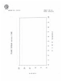
*** Performance data is reflective of one fan ***
Duty
Supply
Qty
Mfr.
Model
Size
Dia
1
Twin City
BC-SW
150
15
X Bolted Door
X Drain w/ plug
Rot./Dis.
IN
3
CW/BHD
Screen Enclos.
Removable Panel
TSP
ESP
IN WG
Fan
BHP
RPM MRPM
OV
IN WG
1,700
10.50
5.00
4.30
3,565 4,253
1,587
X
% Wheel Width
ACFM
3
X Inlet Screen(s)
X Nylon Fan Lube Lines (Std)
Monorail - Fan & Motor
Cl. Arr.
SPB Bearings
50
FPM
HP w/ belt losses:
4.56
X L10-200K Hrs Bearing Life
Large Enough to Remove:
Fan & Motor
*** See attached curve(s) for additional performance data ***
Notes: 1) Provide permanently attached directional rotation arrow, painted to contrast with background.
2) BAH to provide an aluminum fan wheel.
MOTOR
Duty
Supply
Qty
Mfr.
1 Weg
Type
Efficiency
HP
Nom. RPM
Volt./Ph/Hz
Frame
TEFC
Premium
5
3600
460/3/60
184T
Wgt. LB Pos.
89
W
X Suitable for use w/ VFD
X Extended vinyl motor lube line, if applicable
Notes: 1) Motor ground wire to be attached to a ground bar option in its disconnect switch.
2) AHU nameplate to indicate voltage and full load amps.
V-BELT DRIVE
Duty
Supply
Mfr.
T.B. Woods
Type No.
F
Belts
Ctrs.
Shv.
IN
OD
1 5M160009 24.61
( F = Fixed drive, A = Adjustable drive)
4.66
Motor
Bore
Keyway
Shv.
OD
IN
1.125 5/16 X 5/32
4.41
1.688
IN
Fan
Bore
SF = 1.3 x MHP
Keyway
RPM
3/8 X 3/16
3,706
Drive assembly supplied w/ tool-free belt guard w/ tach holes.
MRPM
Range
3,748
Extra set of V-belts
No
Notes: 1) BAH to provide a stainless steel belt guard.
2) BAH to provide a synchronous drive and belts.
VIBRATION ISOLATION
Duty
Supply
Mfr.
Amber Booth
Qty
4
Deflect. IN
Base Type
2
Inertia*
Seismic
Isolation
Yes
Series Type
SWSR
% Eff.
99.9
Fan Thrust
Restraints
Required
* - Concrete by BAH.
Notes:
Page 2 of 8
9/25/2013 1:47 PM
Air Handling Unit Information
Sales Order:
Job Order:
130079-01
Dwg. No.: E-13331-1
13331
Revision:
Data Sheets
C
AC2000 Data Sheets, Version 6.30
HUMIDIFIER
Mfr.
Dri-Steem
Qty
Model
Tube
Centers
H x W
1 Ultra-Sorb LV
12 x 22
In.
Absorption
Distance
3
18.0 In.
Cap.
Steam
LBS/HR
PSIG
Type of
Steam
Act. By
Type
Signal
109.0
15.0
Clean
BAH
Pneu.
TBD
Safing Required
Yes
*** Parts (valves, strainers, F&T traps, etc.) shall ship loose in the AHU for field installation by others. Reference Piping section. ***
Notes: 1) BAH is providing the STS generator, humidifier panel, control valve, valve actuator (control range of 3-15 PSI), strainer,
trap.
2) All interconnecting and supply piping is furnished and installed by others.
3) Humidifier condensate drain connection to be extended to RH side of unit.
4) STS generator shipped loose. Field installation by others.
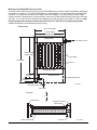
DESICCANT DEHUMIDIFIER
Notes: 1) BAH to provide a Munters Cargocaire Dehumidifier Model HCD-2250-SBA.
2) The dehumidifier is provided with the following:
a) Remotely mounted NEMA 4 control enclosure with indicating package for reactivation heat, reactivation fan, and
energy modulation reactivation damper (damper is a Johnson damper with a Honeywell actuator). Control panel
includes a step down transformer to provide power to low voltage devices.
b) Siemens S-7 PLC with the OM 73 dual line screen for reactivation and desiccant wheel control. Modbus
compatibility is provided with all control integration provided by others.
c) 1 inch Armaflex interior insulation thoughout supply air plenum to minimize heat transfer and external condensation.
d) Interior aluminum cladding.
e) Reactivation fan, 12-1/2" direct drive, 3 HP motor to allow 1.50" ESP.
f) Reactivation filters, 30% AAF AmAir HT (HT-500) and 65% AAF Varicel HT.
g) Reactivation steam coils, quantity 3, designed to operate with 96 PSIG steam (3 supply and 3 condensate connections).
h) Fused Disconnect Switch with grounding bus bar.
3) 460V power and control connections to the control enclosure by others.
4) BAH to provide and install a Photohelic gauge across the reactivation filters. Refer to the filter section for specifics.
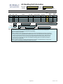
FILTER
Mfr.
H
x
W
1
1
x
x
1
Cube Riga-Flo MV11
30
65
1
24x24x 12
Serv.
Up
Up
Panel AmAir HT (HT-500)
Cube Varicel HT
30
65
1
1
x
x
1
1
24x24x 2
24x24x 12
Up
Up
Type
Model
A Camfil-Farr
Panel 30/30
A Camfil-Farr
% Eff
Cl.
Size(s) IN
24x24x 2
Frame Mat'l
Gauge
Stainless Stl.
Stainless Stl.
0-2" Photohelic
B
C AAF
C AAF
Ship Filters With Unit(s)
BAH shall supply
0
0-2" Photohelic
set(s) of extra filters
Notes: 1) BAH to mount the Camfil-Farr 30% & 65% filters in a single stainless steel Camfil-Farr Type 8 filter frame.
2) The supply air 30% filters are to be Camfil-Farr part number 049880005.
3) The supply air 65% filters are to be Camfil-Farr part number 402994001.
4)
5)
6)
7)
8) BAH to provide a Dwyer Photohelic gauge part number 3002-MR LT for each filter bank (2 total).
9) The Photohelic gauges will be mounted in a NEMA 3R common electrical enclosure. Pneumatic tubing from the
gauges to the enclosure will be by BAH. Connection voltage to the gauges to be 24VDC.
10)
11) BAH to provide a 3-way brass diverting ball valve (McMaster Carr catalog number 46095K61or equivalent) on each
Photohelic high and low pressure port. These valves must be easily accessible.
12)
13)
14) The AAF filters are provided with the Munters Cargocaire unit. BAH to provide and install the Photohelic gauge only.
Page 3 of 8
9/25/2013 1:47 PM
Air Handling Unit Information
Sales Order:
Job Order:
130079-01
Dwg. No.: E-13331-1
13331
Revision:
Data Sheets
C
AC2000 Data Sheets, Version 6.30
COIL
Depth
Duty
Pre-Heat
Qty
1
Mfr.
Aerofin
Pre-Cool
RHC-1
RHC-2
Re-Cool
1
1
1
1
Aerofin
Aerofin
Aerofin
Aerofin
Model
Fins / Mat'l.
BNF-12.0AW-29.0 X 24.0-1-1
0.010" Al
W-11.0Aw-30.0 X 26.0-8-0.5 0.0095" Al
BNF-10.0AW-20.6 X 26.0-2-1
BNF-12.0AW-20.6 X 26.0-1-1
W-9.0AW-16.5 X 26.0-4-0.5
0.010" Al
0.010" Al
0.0095" Al
Tube Size /Mat'l.
5/8" OD x .035" Cu
5/8" OD x .035" Cu
5/8" OD x .035" Cu
5/8" OD x .035" Cu
5/8" OD x .035" Cu
*** See attached coil selections for performance data ***
Coil Racks:
No
Eliminators:
No
If 'Yes' for:
IN
Csg. Mat'l.
304 SS
5.0
304 SS
304 SS
304 SS
304 SS
12.5
5.0
5.0
7.5
Hdr/Con
Mat'l.
CS
CS
CS
CS
CS
Con/Pull
Hand
LH/LH
LH/LH
LH/LH
LH/LH
LH/LH
CS = Carbon Steel
RB = Red Brass
Rack Mat'l.:
Type:
Troughs/Downspouts:
No
If 'Yes' for:
Mat'l.:
Notes: 1) Aerofin to provide a loose set of manufacturing labels with model numbers identical to what is shown on the coil
performance sheets. BAH shall install these labels on the exterior of the unit on the coil removable panels.
2) All coil connection are to be capped for protection during shipping.
3) All coil connections will be MPT.
4) BAH to provide and mount a single bulb thermometer in the access section between the pre-heat coil and the CC.
the thermometer will be a Schneider Electric Model Number TC-4111 (TEI P/N ELC90411A) sensing bulb. BAH to
mount the thermostat junction box on the roof of the unit (door side). Adjust setpoint to 40°F. BAH to wire from
the thermostat junction box to the common electrical enclosure. Sensor to be mounted through the roof of the
unit and the tip is to be located in the center of the airstream. Mounting system for the sensor to be similar to
that used for the Vaisala sensor.
5) BAH to provide and install a Pyromation averaging RTD with transmitter on the downstream face of the pre-heat
coil. Model # is 2290L3(23)(3)-288-8HN63-T440-385U-S (0-100°C).
Page 4 of 8
9/25/2013 1:47 PM
Air Handling Unit Information
Sales Order:
Job Order:
130079-01
Dwg. No.: E-13331-1
13331
Revision:
C
Data Sheets
AC2000 Data Sheets, Version 6.30
MIXING & DISTRIBUTION
Des. Face
Damper
Des. ByPass Damper
Mfr.
Ruskin
Ruskin
Ruskin
Model
CD50
CD50
CD50
Balancing
Damper
5 HC Face
Damper
6 RCC Bypass Damper
Ruskin
Ruskin
Ruskin
CD50
CD50
CD50
No.
1
2
3
Duty
Outside Air
Type
Damper
4
Distribution
Diffuser
BAH
Qty W IN x H IN
1
18 x 12
1
30 x 24
1
36 x 13
1
36 x 13
2
36 x 22
1
36 x 18
Mat'l
AL
AL
Blade
Parallel
Opposed
AL
AL
AL
AL
Opposed
Opposed
Opposed
Opposed
Fail Pos. Act. By Type
Signal
Closed
N/A
BAH Pneu.
Closed
BAH
Elec. 4 to 20 mA
Open
BAH
Elec. 4 to 20 mA
N/A
N/A
N/A
N/A
Closed
BAH
Elec. 4 to 20 mA
Open
BAH
Elec. 4 to 20 mA
Full-Width x Full-Height
Damper No. that have modulating operators: 2,3,5 & 6
or have two-position operators: 1
Notes: 1) Outside air damper (low leakage type):
a) Blade seal and bearings shall withstand temperatures from -30°F to 150°F.
b) Supplied with stainless steel bearing sleeves, shaft, and linkage.
c) BAH to provide with an open & closed limit switch on the damper -(2) Allen Bradley catalog number 440P-MALS11E.
d) BAH to provide a TAC (formally Siebe) pneumatic actuator catalog no. MK-3121, spring fail closed.
e) With actuator, provide solenoid valve (ASCO catalog number 8320G184, 24VDC).
f) BAH to provide a brass needle valve on exhaust port of the solenoid valve & adjust so damper closes in 45 seconds.
g) BAH to provide a muffler on the exhaust side of the O/A damper solenoid valve. If installed inside the control
enclosure, the exhaust air must be ported to the outside of the enclosure.
h) BAH to provide a 1/4" tube fitting for customer use on the exterior of the unit. The fitting will be used to provide
supply air to the damper. BAH to extend pneumatic tubing from the fitting to the supply side of the damper actuator.
i) Actuator is to mount on the interior of the unit.
2) Face-and-bypass dampers (Dehumidifier and Final Heating Coil/Re-Cooling Coil):
a) Blade seal shall withstand temperatures from -30°F to 250°F.
b) Supplied with stainless steel shafts and bearing sleeves suitable for high temperature conditions.
c) Spring return actuator shall be Johnson Controls No. M9220-HGA-3 (24VDC), wired to common elec enclosure.
Provide a 500 ohm resistor for 4-20 mA control of the actuator. Mount resistor in common elec enclosure.
d) Actuator direct coupled to damper shaft. Face and bypass dampers are linked together. Tie rod shall be
minimum 1/2" diameter and/or weld steel angle to reinforce rod to ensure rigidity during high torque conditions.
e) Actuator is to mount on the interior of the unit.
f) BAH to cycle the F&BP damper and adjust the span to where the “4 mA” position is the same as the fail closed
position (bypass is open), the “12 mA” position to be 50% open, and the “20 mA” position is the face damper fully
open and the bypass is closed.
3) All damper jackshafts to be larger than standard (3/4" minimum).
4) The balancing damper is provided with a manually operated locking hand quadrant.
5) The final heating coil face & bypass damper will be linked to the downstream final heating coil face damper. The
damper jackshafts to extend through the casing wall on the RH side of the unit. The interconnecting linkage will be
located on the exterior of the RH side of the unit. BAH to seal all penetrations through the unit casing. The actuator
model and quantity of actuators may change or increase depending on what is required for proper operation. BAH to
determine and advise.
Page 5 of 8
9/25/2013 1:47 PM
Air Handling Unit Information
Sales Order:
Job Order:
130079-01
Dwg. No.: E-13331-1
13331
Revision:
C
Data Sheets
AC2000 Data Sheets, Version 6.30
ELECTRICAL
120V Single Point Wiring*:
Yes , Motor Single Point Wiring*:
Yes
@
460V
Conduit Material: Rigid aluminum
Switches
Mtr. Non-Fused Disconnect(s)
Mtr. Fused Disconnect(s)
Qty
1
1
NEMA
3R
3R
Voltage
460V
460V
SPW NEMA Enclosure(s):
3R
ETL Label: No
HP
5
3
Supplied By
BAH
Munters
Mounted By
BAH
Munters
Component Served
Supply Fan
Dehumidifier
Notes: 1) BAH to mount the motor disconnect switch near the fan access door.
2) BAH to wire the motor ground wire to a ground bar option in the disconnect switch.(on supply fan and reactivation fan
motor disconnect switches).
3) Provide orange or red '460 Volt' label on the motor disconnect cover.
4) All wiring from various unit mounted electrical components are wired to one (1) 'finger safe' terminal bank located in
one (1) NEMA 3R unit mounted junction box. The junction box shall contain the following:
a) One side of terminal bank shall be reserved for field wiring.
b) Label the terminal bank as 'TB 3'.
c) All signal wires (4-20 mA) are run separate from power wires.
d) All electrical component ground wires shall be attached to one common bus bar located inside the junction box.
5) BAH to use wire ferrules on all termination points.
6) Use aluminum flex conduit for connection to rotating equipment.
7) High voltage and 120V wiring shall be run separate from low voltage (<60 VAC or DC) wires or cable.
8) All wire ends at termination and splits must be numbered according to electrical diagram.
9) All conduit to run as close to the top of the unit as possible and be secured to the AHU wall or roof. No conduit
is allowed on or near the floor of the unit. Conduit not to run across any plug panels or access openings. Conduit to
be routed in a manner that the coil removable panels will not be hindered or that the conduit comes in contact with
the coil connections.
10) Use twisted shielded pair for all signal wires. Sheathing is plenum grade (FA).
11) All control components and control loops must be tested at the main terminal bank. Do not test at the individual
device. Attach all internal checkouts pertaining to control tests. Passing initial must be clearly shown. Provide copy
of test reports in O&Ms.
12) The 120V power wiring shall use the following color scheme:
a) Phase A - black
b) Phase B - red
c) Phase C - blue
d) Neutral - white
e) Ground - green
13) The 460V power wiring shall use the following color scheme:
a) Phase A - brown
b) Phase B - orange
c) Phase C - yellow
d) Neutral - gray
e) Ground - green
14) BAH to provide auxiliary contacts in the motor non-fused disconnect switch for use with the customer supplied
VFD (VFD's provided and installed in the field by someone other than BAH).
15) All wiring is to be 600V rated type THHN in dry locations and type THWN in wet locations.
16) All wiring to be minimum 12 GA.
Page 6 of 8
9/25/2013 1:47 PM
Air Handling Unit Information
Sales Order:
Job Order:
130079-01
Dwg. No.: E-13331-1
13331
Revision:
C
Data Sheets
AC2000 Data Sheets, Version 6.30
TESTING & SERVICES
BAH shall provide the following factory test(s) in presence of customer(s) with two (2) weeks notice:
None
X
Velocity Profile (ES-8108)
Performance (ES-8104)
Vibration (ES-8107) in accordance with ANSI S2.19, Grade G6.3, w/
Leakage* (ES-8110, Neg./Pos. Pressure - Orifice Plate)
* - Minimum allowable leakage shall be 50 CFM.
Max.
0.16 IPS filtered in maximum vibration allowed.
% of design CFM @
Total CFM Allowed at negative
times the operating pressure.
" WG & positive
" WG
BAH shall provide the following field service(s) :
X
None
Start-up
Start-up Supervision
Notes: 1) BAH to complete an Inspection/Testing checkoff sheet provided by Thomas Engineering, Inc. Should any deficiences
be found, they are to be recorded on the Inspection Report form.
MISCELLANEOUS NOTES
1.
BAH to mount customer supplied Dew Point Sensor and Transmitter (Vaisala Model HMT 335, TEI P/N ELC90631A, 24VDC) in the
roof of the unit between pre/intermediate filters and the pre-heat coil. The transmitter is to be mounted on the LH side of the unit
near the Dew Point Sensor. BAH to wire from the transmitter to the common electrical enclosure. (For use with the cooling coil). The
Dew Point Sensor and Transmitter will remain installed for shipment. BAH to keep the original package and ship with the unit.
2.
All internal air lines shall be metal and not run across any plug panel openings. All lines at termination and splits must be labeled or
numbered for ease in assembly or troubleshooting. All lines are to be secured to the AHU wall. It is acceptable for tubing to be run on
the side of the unit opposite the doors. Tubing located here should be mounted as close to the unit as possible.
3.
Provide laminated labels as previously provided on S/O #120030 (TCS41152A) and secure with TEK screws. Labels to be white w/
3/8" black lettering (capitalized). Labels to have 9/32" hole located near each end for mounting and be no wider than 6". Labels are
as follows in BOLD:
a) OA damper - INLET DAMPER AIR SUPPLY. Secure label to air supply bulkhead for pneumatic actuator. Add to label
description the 25# operating air supply pressure required.
b) OA damper limit switches - ZSO 100 (damper open switch) …… ZSC 100 (damper closed switch)
c) OA damper actuator - FZ 100
d) OA damper solenoid valve - YV 100
e) OA damper needle valve - FCV 100
f) Pre/Intermediate filter gauge - PRE & MEDIUM FILTER
g) Pre and Medium filter gauge - PDIS 200
h) Photohelic gauges ports - PRE/MEDIUM TEST PORT HIGH, PRE/MEDIUM TEST PORT LOW, REACTIVATION
PRE/MEDIUM TEST PORT HIGH, and REACTIVATION PRE/MEDIUM TEST PORT LOW.
i) Diverting ball valves - Label handle RUN and TEST
j) Heating coils - STEAM SUPPLY and CONDENSATE RETURN
k) Pre-heat coil RTD transmitter - TT 110
m) Final heating coil F&BP actuator - TCZ 150 / TY 150 (if the actuators have a master/slave relationship, label master as
TCZ 150A / TY 150A and label the slave as TCZ 150B / TY 150B
n) Dehumidifier F&BP actuator - MCZ 131 / MY 131 (if the actuators have a master/slave relationship, label master as
MCZ 131A / MY 131A and label the slave as MCZ 131B / MY 131B
p)
q)
r) Reactivation Pre and Medium filter gauge - PDIS 220
s) Cooling coils connection tagged: WATER SUPPLY and WATER RETURN
t) Cooling (Dehumidification) Vaisala Dew Point Sensor with Transmitter tagged: MT 131
u) Schneider Electric Freeze Protection Thermostat to be labeled: TS 001
v) Terminal Bank: TB 3
w) AHU Auxiliary Contact: ES 100.
Page 7 of 8
9/25/2013 1:47 PM
Air Handling Unit Information
Sales Order:
Job Order:
130079-01
Dwg. No.: E-13331-1
13331
Revision:
C
Data Sheets
AC2000 Data Sheets, Version 6.30
4.
Do not ship loose items in a coil section. Customer does not want to risk damaging any coil fins during shipment.
5.
BAH to make sure the unit nameplate contains the following information:
a) TEI Document Number: TCS41704A
b) TEI Air Handling System Serial No: AHU 00407
c) Buffalo Air Handling Serial No: 130079-01
6.
BAH to complete an Inspection/Testing checkoff sheet provided by Thomas Engineering, Inc. The checkoff sheet is a one page
document. Should any deficiences be found, they are to be recorded on a separate form.
7.
All exposed openings on the air handler are to be sealed shut.
8.
9.
Unit to be shipped on a wooden skid. Must use heat treated lumber. Fork lift must be able to pull the skid off of a truck. Skid must
extend beyond the largest item protruding off of the AHU.
REVISIONS
Rev. Date of Change Init.
Description of Change(s)
I.J. 1. FILTER NOTE 4 - "GEL" WAS "GASKET".
A. 6/25/2013
2. FILTER NOTE 7 - "A-4S" WAS "B-1S".
3. MIXING NOTE 2C - "HGA" WAS "GGA".
4. HUMIDIFIER NOTE 1 - ADDED CONTROL RANGE.
CHG'S PER C.O. #12895
I.J. 1. UNIT CONSTRUCTION NOTE 7 - ADDED.
B. 8/26/2013
2. V-BELT DRIVE NOTE 2 - ADDED.
3. FAN NOTE 2 - ADDED.
4. VIBRATION ISOLATION BASE TYPE WAS STRUCTURAL.
5. DELETED HEPA FILTER BANK "B" AND FRAMES.
6. FILTER NOTES 4-7,10,13 - DELETED.
7. FILTER NOTE 9 - CONNECTION VOLTAGE WAS 120VAC.
8. UNIT CONSTRUCTION NOTE 1 - DELETED "CONTINUOUSLY WELD .......".
9. UNIT CONSTRUCTION NOTE 2 - DELETED.
10. ADDED DAMPER OPERATOR TYPES (TWO POSITION OR MODULATING).
11. MISC. NOTE 3G - WAS SUPPLY AIR PRE/INTERMEDIATE FILTER GAUGE - PDIS 200.
12. MISC. NOTE 3R - WAS SUPPLY AIR PRE/INTERMEDIATE FILTER GAUGE - PDIS 220.
13. DRAIN PAN CONNECTION HAND WAS LEFT HAND.
14. HUMIDIFIER NOTE 3 - ADDED.
CHG'S PER C.O. #12965
15. DESICCANT DEHUMIDIFIER NOTE 2A - "REMOTELY MOUNTED" WAS "FACTORY WIRED".
16. FILTER NOTE 12 - DELETED.
17. FILTER NOTE 8 - QTY WAS (3).
18. MISC. NOTE 3H - DELETED "HEPA TEST PORT HIGH" AND "HEPA TEST PORT LOW".
19. MISC. NOTE 3P - DELETED.
20. MISC. NOTE 3Q - DELETED.
21. MISC. NOTE 8 - DELETED.
22. DEHUMIDIFIER/FAN SECTION WEIGHT WAS 2,700#.
23. DISCHARGE SECTION WEIGHT WAS 2,100#.
CHG'S PER NEW INFO
C.
9/6/2013
M.C. 1. ADDED DRIVE INFO.
2. REVISED FAN PERFORMANCE
PER 12983, 12979
Page 8 of 8
9/25/2013 1:47 PM
E-13331-1 C
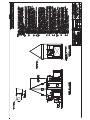
2
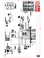
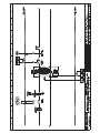
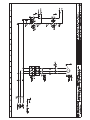
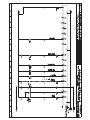
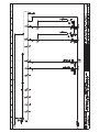
Fans
3
Motors
!"
#
$!
% & $
'!! '
"
(
+
(
$!
(!!!
!
2!"
3
56
56
78!89
!
(!!! 56
'
6< "
8!!
56
>
;
--!
:
!
"
;$
A
<
"
&
;
!
>
!
)*
,$
./
,
0)1
)*.2
),4
)),**
0,
**
0*!:;
01
41
'
(
)=
,79
,
?#@*?#
8$,,
))!:
;!:
.4'79
'
"
3
"
"
>!
C
.0BB
..BB
5
1
0,1
,1
$
;
:-
#
6
$<
;
)4
),
0.
;;
-719
)),
)),
).,
#
'
'$<
;
$
;
719
#
$!
% & $
'!! '
"
+
(
(!!!
(
2!"
8!!
3
,$
)*
,
./
)*.2
(
),4
56
78!89
--!
>
;
"
56
'
6< $
;
:-
#
6
0,
,
'
01
41
#
279
;;
-719
#!
$3(+3&##D3235+3+D$D
!"
#3#388##D3235+$
!"
!
7##9
%
!
719
#
$!
% & $
'!! '
"
+
(
(!!!
(
2!"
8!!
3
,$
)*
,
./
)*.2
(
),4
56
78!89
--!
>
;
"
56
'
6< $
;
:-
$
#
6
0,
,
'
01
41
'#
!
7889
(
#
'
0,
(
,,
4.4
C
4*
,,
5&
,.
E
E
,4*
'
.4.4
,
'
.
=
$F
=
4
)..
'
0,
3
4)*
+
4*
*.
*
'
$
)0*
D
,
,
00
#
,).
*
'(
,.
'
0,,4
%
0,
*,
(
*,
55
,,
(!"
(,*
''
*
.
(
)*8$,,
% & $
'!! '
"
#
#
6
$
;
:-
,
0
)
4
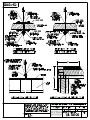
Coils
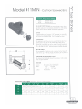
Special-Purpose
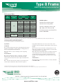
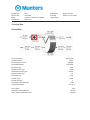
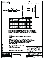
Configuration Code SP06
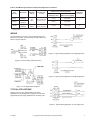
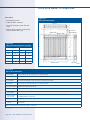
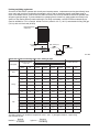
RTD Averaging Sensor
The averaging RTD sensor listed below measures the temperature over the entire sheath length to provide an average temperature
measurement of the cross sectional area of air ducts, room gradient temperatures, and other low temperature averaging applications. The
-1 temperature coefficient within a
!
!!$+;=;>?@[
\@
supplied in various lengths up to 828 inches. All RTD sensors 48 inches and longer will be shipped in a coiled configuration. The sensors on this
page can be provided with a (4 to 20) mA Transmitter integrally mounted inside the available enclosures.
6" TEFLON® LEADS STRIPPED
1/2" & TINNED - 3 WIRE RTD
1/2" NPT STEEL HEX NIPPLE
Ø3/16" - 1/4" SOFT
COPPER OR 316 SST
3 1/2"
NOMINAL
X
ORDER CODES
1
2290L 3(23)3
Example Order Number:
1
2
-
4
2880 4
RTD Averaging Sensor
8HN 63 T440
Head Mounting Fittings
CODE
DESCRIPTION
CODE
2290L
]
?=;>
8HN
2
Sheath Material and Diameter
CODE
6HN
DESCRIPTION
DIAMETER (inches)
MATERIAL
5
!
[
Copper
CODE
!
Copper
[
[
[
3
AVAIL. LENGTHS (inches) DIAMETER O.D. (inches) BENDABILITY
12
[
Rigid
24
[
Rigid
[
[
Rigid
!
[
Bendable
!
!
Bendable
DESCRIPTION
!!;
steel hex nipple
!!;
steel hex nipple
Terminations
22(06)
Length
DESCRIPTION
6" individual Teflon®
leads with terminal pins
Aluminum screw-cover
head
49
+]
\
47
2" x 4" electrical
handibox
Options
HT
+
\\
on hex
T-440
4-20 mA head-mounted
transmitter
(see instrument section)
_
\
^
?=;>_
`{|}
}$
}
}~
\
TEMPERATURE
ºC
ºF
TEMPERATURE
ºC
ºF
!+$
!
[+$
1.6
2.9
![+$
1.4
!
[+$
1.7
+$
2.7
!!+$
1.8
!
;® is a registered trademark of E. I. du Pont
de Nemours and Company.
© 2006 Pyromation, Inc.
SP-6
1IPOF
t'"9
PS
tXXXQZSPNBUJPODPN
172-8
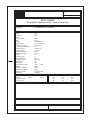
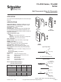
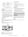
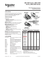
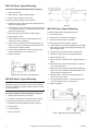
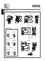
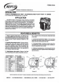
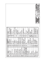
TC-4100 Series, TC-4200
Series
Bulb Thermostats & Return Air Thermostats
General Instructions
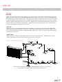
APPLICATION
For on-off control of media temperature in ducts, tanks, liquid
lines, etc.
SPECIFICATIONS
Setpoint Dial Range: Dial plate is marked as F on one
side and C on the other. See Table-2 for specific ranges.
Sensing Element: Liquid-filled copper.
Differential: See Table-2.
Dual Bulb Units: One bulb senses the controlled media;
the second bulb senses the outside air temperature. The
temperature of the controlled media increases as outside air
temperature decreases.
Ambient Temperature Limits:
Case,
Shipping -40 to 160F (-40 to 71C).
Operating -40 to 150F (-40 to 65C): except return
air bulb unit, -40 to 140F (-40 to 60C).
Bulb, See Table-2.
Electrical Switch: Snap action SPDT, one per stage.
Ratings, See Table-1.
Connections: Coded screw terminals.
Cover: All metal with 1/2" to 3/4" conduit openings.
Case Locations: NEMA Type 1 indoor only.
Mounting: Case can be mounted in any position. See
ACCESSORIES for bulb mounting kits (order separately).
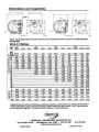
Dimensions:
Case, 4-5/8" high x 2-1/4" wide x 2" deep (117 mm x 57
mm x 51 mm)
Element and Capillary, See Table-2.
ACCESSORIES
AT-201
AT-203
AT-206
AT-208
AT-209
AT-210
AT-211
Copper bulb well requires AT-209
Stainless steel bulb well requires AT-209
Copper bulb well
Duct mounting kit
Bulb mounting kit
Concealed adjustment plate
Outside bulb shield
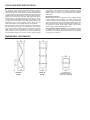
Typical
Single Bulb
Typical
Return Air Bulb
Typical
Dual Bulb
Typical Single Stage
N.C.
Common
Temp. Drop
N.O.
N.O. makes ON temperature drop
Typical Two Stage
Low (N.C.)
1st stage cool
Table-1 Maximum Electrical Rating
(All units except TC-4115*)
Low
Temp. Drop
Common
Switch Rating (50/60
Hz)
24V
120V
240V
Full Load Amps
9.8
9.8
8.0
Locked Rotor Amps
58.8
58.8
48.0
60
360
360
22
22
22
16
16
8.0
Pilot Duty VA
Low (N.O.)
Non-Inductive Amps (Resistive)
Single Stage
Two Stage
High (N.C.)
High
Common
Temp. Drop
High (N.O.)
1st stage Heat
* TC-4115 for TAC System 8000 and applications requiring less than one (1)
amp. Electrical Rating: 1.0 amp at 24 Vac; 0.25 amp at 24 Vdc.
Figure-1 Switch Action and Terminal Identification.
Printed in U.S.A.
11/09
Copyright 2009 Schneider Electric All Rights Reserved.
F-18895-7
Table-2 Specifications.
Part
Number
Type
TC-4111
Single Stage
Single Bulb
100 to 260
(38 to 127)
TC-4123
190 to 350
(88 to 176)
Single Stage
Dual Bulb
70 to 120
(21 to 49)
Single Stage
Return Air
Bulb
50 to 90
(10 to 32)
TC-4211
TC-4222
Two Stage
Single Bulb
20 (6)
-40 to 170
(-40 to 77)
6 (1.8)
-40 to 310
(-40 to 154)
Factory Set 3 (2)
Adj. 3 to 16 (2 to 9)
-40 to 170
(-40 to 77)
-40 to -310
(-40 to 154)
10 (3)
Armored
-40 to 400
(-40 to 204)
1:1
30 (9)
Each Bulb
3/8 x 4
(9.5 x 10²)
3/8 x 5-1/2
(9.5 x 140)
Factory Set 3 (2)
Adj. 1-1/2 to 10 (1 to 5)
3/8 x 4
(9.5 x 10²)
3/8 x 4
(9.5 x 10²)
Factory Set 3 (2)
Adj. 3 to 16 (2 to 9)
Coiled
2-1/2 x 2 (64 x 51)
None
Total of indoor and
outdoor
temperatures
must not exceed
280 (138)
-40 to 145
(-40 to 63)
Fixed 2 (1)
6 (1.8)
100 to 260
(38 to 127)
-40 to 170
(-40 to 77)
3/8 x 4
(9.5 x 10²)
10 (3)
Armored
Per Stage Fixed 3 (2)
Between Stages Set 3 (2)
Adj. 2 to 10 (1 to 5)
1:1-1/2c
TC-4251
Two Stage
Dual Bulb
70 to 120
(21 to 49)
TC-4252
30 (9)
Each Bulb
1:1
Two Stage
Return Air
Bulb
-40 to 310
(-40 to 154)
-40 to 400
(-40 to 204)
190 to 350
(88 to 176)
TC-4223
TC-4266
Outdoor
3/8 x 4
(9.5 x 10²)
-40 to 120
(-40 to 49)
TC-4221
Indoor
Safe Bulb
Temperature
Range
F (C)
Differential
F (C)
6 (1.8)
1:1-1/2c
TC-4151
TC-4166
Bulb Copper
in. (mm)
-40 to 120
(-40 to 49)
TC-4122
TC-4152
Capillary
Copper
ft. (m)
100 to 260
(38 to 127)
TC-4112
TC-4121
Dimensions
Duala
Bulb
Ratio
-40 to 120
(-40 to 49)
TC-4111-020
TC-4115b
Setpoint
Adjustment
Range
F (C)
50 to 90
(10 to 32)
None
3/8 x 4
(9.5 x 10²)
3/8 x 5-1/2
(9.5 x 140)
Per Stage Fixed 3 (2)
Between Stages Set 3 (2)
Adj. 1.5 to 6.5 (1 to 4)
3/8 x 4
(9.5 x 10²)
3/8 x 4
(9.5 x 10²)
Per Stage Fixed 3 (2)
Between Stages Set 3 (2)
Adj. 2 to 10 (1 to 5)
Coiled
2-1/2 x 2 (64 x 51)
Each Stage Fixed 2 (1)
Between Stages Set 3 (2)
Adj. 1 to 5 (0.5 to 3)
Total of indoor and
outdoor
temperatures
must not exceed
280 (138)
-40 to 145
(-40 to 63)
a
b
First number of reset ratio typically indicates outdoor air temperature change required to increase the setpoint by the second number.
See Electrical Rating.
c
For 1-1/2:1 ratio, reverse bulbs and use extra dial supplied with unit.
Table-3 Ratio Selection Table.
Outdoor
Temperature
in F
Ratio
-30
Change in Water Temperature for Different Ratios as
Outdoor Temperature Drops from 70°F to Design Temperature
Dial Set at 70F
Dial Set at 80F
Dial Set at 90F
Dial Set at
100F
Dial Set at
110F
Dial Set at 120F
1 to 1-1/2
1 to 1
1-1/2 to 1
70 to 220
70 to 170
70 to 137
80 to 230
80 to 180
80 to 147
90 to 240
90 to 190
90 to 157
100 to 250
100 to 200
100 to 167
110 to 260
110 to 210
—
120 to 270
120 to 220
—
-20
1 to 1-1/2
1 to 1
1-1/2 to 1
70 to 205
70 to 160
70 to 130
80 to 215
80 to 170
80 to 140
90 to 225
90 to 180
90 to 150
100 to 235
100 to 190
100 to 160
110 to 245
110 to 200
—
120 to 255
120 to 210
—
-10
1 to 1-1/2
1 to 1
1-1/2 to 1
70 to 190
70 to 150
70 to 123
80 to 200
80 to 160
80 to 133
90 to 210
90 to 170
90 to 143
100 to 220
100 to 180
100 to 153
110 to 230
110 to 190
—
120 to 240
120 to 200
—
0
1 to 1-1/2
1 to 1
1-1/2 to 1
70 to 175
70 to 140
70 to 117
80 to 185
80 to 150
80 to 127
90 to 195
90 to 160
90 to 137
100 to 205
100 to 170
100 to 147
110 to 215
110 to 180
—
120 to 225
120 to 190
—
+10
1 to 1-1/2
1 to 1
1-1/2 to 1
70 to 160
70 to 130
70 to 110
80 to 170
80 to 140
80 to 120
90 to 180
90 to 150
90 to 130
100 to 190
100 to 160
100 to 140
110 to 200
110 to 170
—
120 to 210
120 to 180
—
+20
1 to 1-1/2
1 to 1
1-1/2 to 1
70 to 145
70 to 120
70 to 103
80 to 155
80 to 130
80 to 113
90 to 165
90 to 140
90 to 123
100 to 175
100 to 150
100 to 133
110 to 185
110 to 160
—
120 to 195
120 to 170
—
+30
1 to 1-1/2
1 to 1
1-1/2 to 1
70 to 130
70 to 110
70 to 97
80 to 140
80 to 120
80 to 107
90 to 150
90 to 130
90 to 117
100 to 160
100 to 140
100 to 127
110 to 170
100 to 150
—
120 to 180
120 to 160
—
C = (F - 32) 5/9.
2
Copyright 2009 Schneider Electric All Rights Reserved.
F-18895-7
DUAL BULB SELECTION
Location
On the dual bulb units, indoor and outdoor bulbs are
determined by the ratio selected (see Table-2). Ratio refers to
the outdoor air temperature change compared to the water
temperature change. The dial setpoint is the water
temperature setpoint when the outdoor temperature is 70F.
Locate the device allowing proper distance to the bulb
location. The case can be mounted in any position. Refer to
Figure-2 for case dimensions.
To select ratio, it is necessary to know only: (1) outdoor design
temperature, (2) maximum water temperature at outdoor
design temperature, and (3) desired water temperature at
70F outdoors. Use Table-3 to determine the required ratio
based on this information and set the dial per item (3).
TC-4166
TC-4266
Only
Note: If a 1-1/2:1 ratio is selected, the extra dial supplied
with the unit must be used.
Example: Select ratio for an installation with a -10F design
temperature and estimated supply water temperature of 75F
at 70F outdoors and 125F at -10F outdoors. From Table-3,
-10F for 1-1/2:1 ratio, note by interpolation (70F to 123F
with dial at 70F, 80F to 133F with dial at 80F) that water
temperature varies from 75F to 128F as outdoor
temperature drops from 70F to -10F.
TC-4166
TC-4266
Only
Cut Hole in
Duct 2-1/4" W x
2-1/2" H for
Mounting in
Return Air
Side
4-5/8"
7"
TC-4166
TC-4266
Only
3-5/8"
TC-4166
TC-4266
Only
Back
7/8"
2"
For this application, the 1-1/2:1 ratio should be selected. The
extra dial supplied with the unit would be used, and the dial set
at 75F.
1/2"
1/4"
1"
2-1/4"
Hole for 1/2" Conduit
Knockout for 3/4" Conduit
13-64"
1-9/16"
5/16"
1-5/64"
PRE-INSTALLATION
Bottom
Inspection
Figure-2 Case Dimensions.
Visually inspect the carton for damage. If damaged, notify the
appropriate carrier immediately. If undamaged, open the
carton and visually inspect the device for obvious defects.
Return damaged or defective products.
Required Installation Items
• Wiring diagram
• Tools (not provided):
Volt-ohm meter
Room temperature thermometer on F or C
Appropriate screwdriver(s) for cover, terminals and
mounting screws
Appropriate drill and drill bit for mounting screws
INSTALLATION
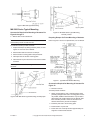
Procedure for Remote Bulb Mounting
Air Bulb Models — Mounting in Return Air Duct
1. Remove cover and provide two holes for #10 round head
screws using the housing as the template or by using the
dimensions shown in Figure-2.
2. Partially insert the mounting screws in the screw holes.
Fit the housing over the screws, slide housing down on
the screws and tighten the screws.
Air Bulb Models — Mounting Outside of Return Air Duct
1. Prepare duct for mounting by cutting hole and providing
mounting screw holes per Figure-2.
2. Fabricate a cover as shown in Figure-3.
Caution:
1. Installer must be a qualified, experienced technician.
2. Disconnect power supply before installation to prevent
electrical shock and equipment damage.
3. Carefully roll bulbs toward back of unit and insert through
2-1/4" x 2-1/2" (57 mm x 64 mm) hole.
4. Remove cover and attach unit to duct with #10 screws.
5. Attach cover over 2-1/4" x 2-1/2" (57 mm x 64 mm) hole.
3. Make all connections in accordance with the electrical
wiring diagrams, and in compliance with national and
local codes. Use copper conductors only.
4. Do not exceed ratings of the device.
5. Avoid locations where excessive moisture, corrosive
fumes or vibrations are present.
F-18895-7
Copyright 2009 Schneider Electric All Rights Reserved.
3
Figure-3 Field Supplied Duct Hole Cover Plate.
Figure-7 AT-201 or AT-203 Installation.
AT-201 or AT-203 Installation (see Figures-6 and 7):
Duct and Outdoor Mounting
1. Install bulb well or adaptor from AT-209 into 3/4" FNPT
opening.
Maximum insertion length is 6 inches.
Duct: Install bulb with AT-208 kit as shown in Figure-4.
2. Place packing nut, washers and packing from AT-209
over bulb support section and insert bulb well or AT-209
adaptor.
3. Push interlocking washers and packing into well or
adaptor and tighten packing nut until firmly sealed.
Figure-4 Duct Mounting with AT-208.
Outdoor: Install with AT-211 kit as shown in Figure-5.
1. Mount bulb to outside wall or surface with bulb clip.
2. Place shield over bulb and fasten to mounting surface.
Figure-8 AT-206 Installation.
AT-206 Installation (see Figures-6 and 8):
1. Install AT-206 bulb well into 1/2" FNPT opening.
2. Place packing (included with AT-206) over bulb support
section and insert bulb into well.
3. Push packing into nut on well using a screwdriver.
Concealed Setpoint and Lock Cover Screw
Order AT-210 concealed adjustment kit separately.
1. Peel off adhesive film from the concealed adjustment plate
and place into the recess of cover.
Figure-5 Outdoor Mounting with AT-211.
Bulb Mounting — Liquid Line and Tank
2. Remove screw from cover.
3. Install lock cover screw provided with AT-210.
Figure-6 Bulb Mounting for Liquid Line and Tank.
4
Copyright 2009 Schneider Electric All Rights Reserved.
F-18895-7
Table-4 Bulb Mounting Installation Hardware And Application Limitations.
a
b
Part
Number
Description
AT-201b
Copper
Bulb Well
AT-203b
Stainless Steel
Bulb Well
AT-206
Copper
Bulb Well
Mounting
Fitting
Insertion Size
in. (mm)
3/4"
MNPT
1/2 (13) dia. O.D.
9-1/2 (241) long
1/2"
MNPT
1/2 (13) dia. O.D.
4-1/2 (114) long
Application Limitations
at 250F (121C) Fluid Temperaturea
Max. Recommended
Velocity fps (m/s)
Max. Recommended
Static Press. psig (kPa)
11 (3.3)
250 (1728)
20 (6.1)
500 (3448)
11 (3.3)
250 (1728)
Installation
per Figure
7
8
Max. recommended fluid temperature is 350 F (177C).
Requires AT-209.
WIRING
The thermostat has one 1/2" to 3/4" conduit opening in the
bottom of the housing. Terminal coding and switch action are
shown in Figures-9 and 10.
Figure-11 Typical Heating Application for Single Stage Units.
Figure-9 Terminal Coding and Switch Action.
Figure-12 Typical Cooling Application for Single Stage Units.
Figure-10 Two Stage Switch Sequence.
TYPICAL APPLICATIONS
Figures-11 and 12 show typical heating and cooling
applications for single stage units. Figures-13 and 14 show
typical heating and cooling applications for two stage units.
Figure-13 Typical Heating Application for Two Stage Units.
F-18895-7
Copyright 2009 Schneider Electric All Rights Reserved.
5
To adjust interstage differential:
1. Disconnect power to unit.
2. Remove cover.
3. Turn adjustor to approximately desired position.
4. Check out by turning dial and noting dial readings where
switch contacts make.
5. After changing interstage differential, recalibrate. See
CALIBRATION.
CALIBRATION
Figure-14 Typical Cooling Application for Two Stage Units.
CHECKOUT
1. With all power disconnected, soak bulb(s) for 10 minutes
at known temperature (must be 70°F for dual bulb).
2. Turn dial and note where switch contacts make.
After installing a thermostat, make an initial check of the
switching action. Verify the switch action by listening to the
switch contacts.
1. Turn the setpoint dial to a temperature above ambient. This
should cause the thermostat to switch, making orange to
brown.
2. Turn the setpoint dial setting down gradually. Orange to
brown must break, making orange to red.
3. Compare the differential of the device to the differential
shown on the performance charts by turning the dial. The
differential of the device is the difference in dial reading
between the make of orange to brown and the make of
orange to red on single switch units.
3. Turn dial midway between click points.
4. Turn the calibration nut (located under dial) until the
temperature of the bulb is indicated on the dial (see
Figure-15).
Note: On two stage units follow above procedure. LO switch
is first stage on cooling applications. HI switch is first stage on
heating applications.
MAINTENANCE
ADJUSTMENTS
Regular maintenance of the total system is needed to assure
sustained optimum performance. Thermostats should be
periodically inspected for dirt or blockage of air over the
elements.
Setpoint
REPAIR
Screwdriver adjustment. Scales dual marked F on front and
C on back. To change scale, remove spring retaining ring,
select scale and replace retaining ring.
Field repair is not recommended. Replace defective device.
Differential
The differential is adjustable by turning the adjustor located on
the side of the device (see Figure-15).
Calibration Nut
(Turn with 1/2"
open end wrench)
Incr. Spread
Differential Adjustment
Figure-15 Adjustments.
Single Stage: Each line represents approximately 3F (2C)
change.
Two Stage: Each notch represents approximately 2F (1C)
change between stages. (Differential per switch is fixed.)
6
Copyright 2009 Schneider Electric All Rights Reserved.
F-18895-7
5
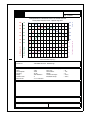
Filters
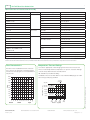
30/30
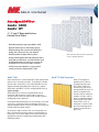
®
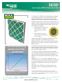
High-Capacity MERV 8 Pleated Panel Filter
The Camfil Farr 30/30 has set the industry standard
for pleated panel filters since 1963. With over 45
design enhancements, it continues to provide the
industry’s best value for medium efficiency filtration.
Setting the standard by which other pleated filters are
judged, modern media manufacturing techniques and
proprietary technological advancements ensure that
the Camfil Farr 30/30 is:
*XDUDQWHHGWRSHUIRUPDWWKH
UDWHGHIILFLHQF\RUEHWWHU
WKURXJKRXWWKHOLIHRIWKH
ILOWHU
*XDUDQWHHGWRODVWORQJHU
WKDQDQ\RWKHUSOHDWHGSDQHO
ILOWHUDYDLODEOH
Performing at MERV 8, using a mechanical particle
capture principle, the 30/30 will not drop in
efficiency while in service as will other pleated panel
filters that incorporate an electret charge to obtain a
MERV 8 value.
The best performing
pleated panel filter
— guaranteed!
Its radial pleat design provides the longest life and
lowest average pressure drop reducing the number of
filter changes so your facility will use less fan power
to move air through the filter.
The high wet-strength beverage frame and welded
wire media backing provide structural integrity in any
type of HVAC application virtually eliminating the
additional costs associated with filter bypass or filter
failure.
Available in 1”, 2” or 4” deep configurations, the
30/30 is ideal for commercial, industrial, institutional
or any other application where the ultimate level of
protection of equipment and indoor air quality is a
concern.
The Camfil Farr 30/30 has an Energy Cost Index
(ECI) of five stars, the highest performance rating
available.
1
Composite minimum efficiency values of the 30/30 when evaluated
per ASHRAE Standard 52.2-2007. The 30/30 has a MERV of 8
and MERV-A of 8 when tested per appendix J.
A 5-Star rating indicates that this filter performs in the top 20% of all products of similar
construction in the HVAC industry. Factors of consideration include maintained efficiency, energy
usage and resistance to air flow. Detailed evaluation information is available from your Camfil Farr
sales outlet or on the web at www.camfilfarr.com.
www.camfilfarr.com
Camfil Farr 30/30
Exclusive MERV 8 Performance from Camfil Farr Media
The highest media weight, more than any other
\
\
\
holding capacity, ensure that the 30/30 will last longer
in any HVAC application.
The 30/30 media is manufactured from a proprietary blend of fibers that incorporate
a mechanical principle of particle capture. The filter does not require an electret
charge which would dissipate and reduce filter’s efficiency after minimal hours of
operation in a system. The media is lofted to a uniform depth to enhance the depthloading characteristic and ensure the longest life of any pleated filter available.
The high-loft also offers a lower resistance to airflow so fan horsepower required
to move air through the filter is minimized. Camfil Farr evaluates the quality of all
incoming raw materials to maintain product integrity as part of a rigorous quality
control program.
Welded Wire Grid Maintains Radial Pleat Design
The media is formed into a radial pleat for uniform dust loading and full use of the media area.
V-style pleats blind while loading preventing full utilization of the media area and increasing the filters
pressure drop resulting in increased energy usage. A welded wire grid, spot welded on one-inch
centers maintains each radial pleat and maintains media stability through varying airflows.
Rounded radial pleats, instead of
v-shape pleats, allow full usage of
media area.
High Wet-Strength Beverage Board Frame
The high wet-strength beverage board frame, the thickest board in the industry, creates a stable
and non-yielding media pack. Filter bypass is virtually eliminated because the filter fits securely in
the filter holding mechanism. The media is bonded to the frame ensuring that all of the air seen
by the filter will be treated by the filter. Diagonal support members are bonded to each pleat to
maintain pleat spacing and add stability to the pack through bridge-style engineering. The 30/30 is
guaranteed to 2.0” w.g. of pressure filter without failure. Costly filter blowouts and compromising
of HVAC system cleanliness is eliminated.
Diagonal support members, glued to
each pleat at its apex, helps maintain
@
_\
\
_
ISO 9001:2008 Certified Quality Control
Every 30/30 filter is identified on the frame with a unique manufacturing code that allows us to analyze every component of construction
from raw materials to the point where the product is boxed for shipping. Filters are inspected for structural integrity so they are capable
of operating in the harshest HVAC system conditions. The adhesiveness of diagonal support members to pleat apexes is inspected so
pleat spacing is uniform to provide longer filter life. Each media lot is laboratory tested to confirm consistent performance and individual
filters are submitted from each manufacturing facility on a strict schedule for ASHRAE 52.2 testing in our world-class testing facility.
The standard of the industry, by Camfil Farr.
Used in many systems as a prefilter, the 30/30 extends the life of final filters by capturing larger contaminant and thereby allowing the
final filters to concentrate on removing smaller particles such as those that are respirable and can cause lung damage. The 30/30 is
also an excellent choice when applied as the only filter in a system to keep coils clean and maintain efficiency, and protect building
occupants from contaminants of annoyance such as pollen, plant spores, atmospheric dusts and other indoor air irritants.
Unprecedented Industry Guarantee
If our filters don’t outlast and outperform your current filters, we’ll replace them, FREE.
For guarantee details and a distributor list, visit www.camfilfarr.com.
www.camfilfarr.com
Camfil Farr 30/30®
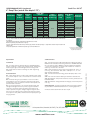
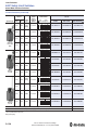
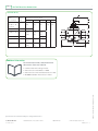
PERFORMANCE DATA
2” Deep Filter (actual filter depth 1.75”)
Part
Number
049880-019
049880-008
049880-009
049880-007
049880-011
049880-001
049880-013
049880-002
402271-007
049880-006
049880-015
049880-012
049880-005
049880-010
049880-020
049880-016
049880-004
049880-014
049880-003
049880-018
Nominal
Depth
(inches)
Nominal
Size
(inches)
Actual Size
(inches)
Depth Height Width
2
16 x 16
20 x 10
20 x 14
20 x 12
20 x 15
20 x 16
20 x 18
20 x 20
20 x 30
24 x 12
24 x 18
24 x 20
24 x 24
25 x 14
25 x 15
24 x 16
25 x 16
25 x 18
25 x 20
25 x 25
15.50
19.50
19.50
19.50
19.50
19.50
19.50
19.50
19.50
23.38
23.50
23.50
23.38
24.50
24.50
24.50
24.50
24.50
24.50
24.50
1.75
15.50
9.50
13.50
11.88
14.50
15.50
17.50
19.50
29.50
11.38
17.50
19.50
23.38
13.50
14.50
15.50
15.50
17.50
19.50
24.50
Initial
Resistance
(inches w.g.)
Airflow
Capacity
(cfm)
0.31
890
700
975
835
1045
1100
1250
1390
2085
1000
1500
1670
2000
1220
1300
1335
1390
1565
1740
2170
Total Media Area Pleats per
(sq. ft.)
Linear Foot
7.8
6.0
8.3
7.4
9.3
9.9
10.8
11.9
18.2
8.4
13.0
14.3
17.3
10.4
11.6
11.8
12.4
13.5
14.9
19
15 pleats per
linear foot
1” Deep Filter (actual filter depth 0.88”)
Part
Number
404207-003
054862-025
404207-005
054862-012
054862-009
054862-016
054862-019
054862-006
054862-008
054862-001
054862-020
054862-002
054862-021
054862-022
054862-010
404207-004
054862-015
054862-028
054862-011
054862-005
054862-023
054862-024
054862-007
054862-013
054862-004
054862-017
054862-003
054862-014
Actual Size
(inches)
Nominal
Depth
(inches)
Nominal
Size
(inches)
Depth Height Width
1
10 x 10
12 x 12
16 x 12
16 x 16
20 x 7
20 x 10
20 x 12
20 x 14
20 x 15
20 x 16
20 x 18
20 x 20
22 x 22
24 x 10
24 x 12
24 x 14
24 x 16
24 x 18
24 x 20
24 x 24
25 x 10
25 x 12
25 x 14
25 x 15
25 x 16
25 x 18
25 x 20
25 x 25
9.50
11.50
15.50
15.50
19.50
19.50
19.50
19.50
19.50
19.50
19.50
19.50
21.50
23.50
23.50
23.50
23.50
23.50
23.50
23.50
24.50
24.50
24.50
24.50
24.50
24.50
24.50
24.50
0.88
9.50
11.50
11.50
15.50
6.50
9.50
11.50
13.50
14.50
15.50
17.50
19.50
21.50
9.50
11.50
13.50
15.50
17.50
19.50
23.50
9.50
11.50
13.50
14.50
15.50
17.50
19.50
24.50
Initial
Resistance
(inches w.g.)
Airflow
Capacity
(cfm)
Total Media Area
(sq. ft.)
Pleats per
Linear
Foot
0.23
240
350
470
620
340
490
580
680
730
780
880
970
1180
580
700
820
970
1050
1165
1400
610
730
850
910
970
1100
1215
1520
1.6
2.5
3.3
4.3
2.4
3.3
4.1
4.6
5.1
5.4
6.1
6.6
8.2
4.0
4.9
5.5
6.7
7.3
8.0
9.8
4.1
5.2
5.7
6.4
6.7
7.6
8.3
10.5
16 pleats
per linear
foot
www.camfilfarr.com
Camfil Farr 30/30®
PERFORMANCE DATA (continued)
4” Deep Filter (actual filter depth 3.75”)
Part Number
059413-004
059413-003
059413-002
059413-009
059413-008
059413-001
059413-005
059413-006
059413-010
059413-007
Nominal
Depth
(inches)
Nominal
Size
(inches)
4
20 x 16
20 x 20
24 x 12
24 x 18
24 x 20
24 x 24
25 x 16
25 x 20
25 x 25
25 x 29
Actual Size
(inches)
Depth
Height
Width
3.75
19.38
19.38
23.38
23.38
23.38
23.38
24.38
24.38
24.38
24.38
15.38
19.38
11.38
17.38
19.38
23.38
15.38
19.38
24.38
28.38
Initial
Airflow
Resistance Capacity
(inches w.g.)
(cfm)
0.27
Total Media
Area
(sq. ft.)
Pleats per
Linear Foot
15.7
18.9
13.9
20.2
22.7
27.7
19.7
23.6
30.0
35.4
11 pleats per
linear foot
1100
1390
1000
1500
1670
2000
1390
1740
2170
2520
Data Notes:
1.0” w.g. recommended final resistance for all depths. System design may dictate an alternative changeout point. Contact factory
for guidance.
The 30/30 has been listed by Underwriters Laboratories as UL 900.
Maximum operating temperature 200º F (93º C).
2” and 4” deep filters rated at 250 feet per minute (fpm) medium and 500 fpm high. 1” deep filter’s rated at 175 fpm medium and
350 fpm high.
For product specification in RTF format please go to www.camfilfarr.com.
Specification
3.0 Performance
1.0 General
3.1 - The filter shall have a Minimum Efficiency Reporting Value of
MERV 8 when evaluated under the guidelines of ASHRAE Standard
52.2. It shall also have a MERV-A of 8 when tested per Appendix
J of the same standard. The media shall maintain or increase in
efficiency over the life of the filter.
3.2 - Initial resistance to airflow shall not exceed 0.23”, 0.31” or
0.27” w.g. at an airflow of 350, 500 or 500 fpm on 1”, 2” or 4”
deep models respectively.
3.3 - The filter shall have an Energy Cost Index (ECI) value of five
stars.
3.4 - Filter shall be listed UL 900 by Underwriters Laboratories.
3.5 - Manufacturer shall provide evidence of facility certification to
ISO 9001:2008.
3.6 - Manufacturer shall guarantee the integrity of the filter pack to
2.0” w.g.
1.1 - Air filters shall be medium efficiency ASHRAE pleated
panels consisting of cotton and synthetic media, welded wire
media support grid, and beverage board enclosing frame.
1.2 - Sizes shall be noted on drawings or other supporting
materials.
2.0 Construction
2.1 - Filter media shall be a cotton and synthetic blend, lofted
to a uniform depth of 0.15”, and formed into a uniform radial
pleat.
2.2 - A welded wire grid, spot-welded on one-inch centers
and treated for corrosion resistance shall be bonded to the
downstream side of the media to maintain radial pleats and
prevent media oscillation.
2.3 - An enclosing frame of no less than 28-point high wetstrength beverage board shall provide a rigid and durable
enclosure. The frame shall be bonded to the media on all
sides to prevent air bypass. Integral diagonal support members on the air entering and air exiting side shall be bonded
to the apex of each pleat to maintain uniform pleat spacing in
varying airflows.
Supporting Data - Provide product test report including all details
as prescribed in ASHRAE Standards 52.2, including Appendix J.
Air filters shall be Camfil Farr 30/30 or equal.
Camfil Farr | 1 North Corporate Drive, Riverdale, NJ 07457 | Tel: (973) 616-7300
www.camfilfarr.com
© Copyright Camfil Farr # 1002 - 0212
4” deep 30/30 is available with a header
for side-access housing installation.
Request Product Sheet 1003.
®
Riga-Flo
High-Lofted Supported Media Box Style Air Filter
The Camfil Farr Riga-Flo® provides high efficiency
ASHRAE air filtration performance in a compact,
supported media design. The materials of
construction preclude contaminant amplification, as
all components are inert to supporting the growth of
captured bacteria or other viable contaminants. The
Riga-Flo:
Is available in four standard efficiencies — MERV
9, MERV 11, MERV 13 and MERV 14 per ASHRAE
Standard 52.2. The Riga-Flo has a MERV-A
value of 9, 11, 13 or 14 when tested using the
conditioning step as specified in Appendix J of
the same Standard.
Includes high-lofted, depth-loading, micro fine
glass media for longer service life and uniform
low resistance to airflow. Filtration efficiency is
maintained throughout the life of the filter.
Has a unique media backing to maintain fiber
blanket uniformity and preclude media migration.
The backing is bonded to the media to support
and maintain tapered radial pleats, and prevent
media oscillation during varying system airflows.
Includes a continuous adhesive bond around the
media pack to eliminate air bypass and ensure
integrity to 10” w.g.
Full utilization of media area
for longer life and performance
that is not affected by varying
Includes an enclosing frame of corrosion-resistant
galvanized steel.
Includes all-metal diagonal support braces to
assure filter rigidity and media pack protection.
Includes unique bridge style plastic contour
stabilizers, mechanically fastened to the diagonal
support braces, on the air entering and air exiting
sides, to ensure pleat support through turbulent
or varying airflows.
Has an ECI1 value of four stars.
The Riga-Flo’s supported media is excellent for VAV
systems or today’s energy and disposal conscious
HVAC applications.
_=
=
?
\
=
\\!!
1
]
\
!\
\
_+
\
\
\__
\
>
\?
?@_+
@
www.camfilfarr.com
®
Riga-Flo
High-Lofted Supported Media Box Style Air Filter
Performance Data
Filter Model
&
1
=]+
=
=]
=]+
=
=]
=]+
=
=]
(cfm)
Media
Area
(sq. ft.)
!!
!
!!!
!
![
!!!
!
[
!]!
!!!
!]!
!!!
!!
!
!]
!!!
!
Part
Number
Nominal Size
Actual Dimensions
(inches)
(H X W X D)
(inches)
(H X W X D)
!]
!!!
!][
!]
Capacity
(cfm)
Media
Area
(sq. ft.)
!!
!
![
!![
!
[
!![
!
!
!]!
!![
!]!
!![
!!
!
![
![
!]
!![
!
[
Initial
Resistance
(inches w.g.)
Part
Number
Nominal Size
Actual Dimensions
(inches)
(H X W X D)
(inches)
(H X W X D)
!]
!![
!][
!]
Capacity
!]
!!!
!
[
!]
!![
!
!
!]
!!!
!]
!![
!]
!!!
!!
!
!]
!![
!!
!
![
!]
!!!
!
![
!]
!![
!
[
!]
!!!
!
[
!]
!![
!
!
!]
!!!
!]
!![
Initial
Resistance
(inches w.g.)
[
!
Riga-Flo MERV 9, as noted below, includes a wire backing on the media.
=
=]
!!!
!!
!
!]
[![]
!!!
!
![
[![]!
!!!
!
[
[![][
!!!
[
DATA NOTES:
6” deep units are only available with metal contour stabilizers.
MERV 9 models, 12” and 6” have a welded wire grid as media support backing.
** Recommended final resistance is 1.5” w.g. System design may dictate a lower change-out point.
1
Respective listed efficiencies are MERV per ASHRAE 52.2 and MERV-A per Appendix J of that Standard.
Maximum continuous operating temperature is 200° F (93° C), intermittent 220° F (104° C).
Listed UL 900 by Underwriters Laboratories.
!![
!!
!
![
!]
!![
!
[
!]!
!![
!
!
!][
!![
_
Options:
Available with header for side-access or front access applications, as shown at right. See Product Sheet 1303PH.
Specifications
3.0 Performance
1.0 General
3.1 - The filter shall have a Minimum Efficiency Reporting Value of (MERV
9, MERV 11, MERV 13, MERV 14) per ASHRAE Standard 52.2. It shall
have a MERV-A of (9, 11, 13, 14)* when tested under Appendix J of that
standard.
1.1 - Air filters shall be high-efficiency ASHRAE high lofted supported media
disposable type assembled in a compact and secure enclosing frame.
1.2 - Sizes shall be as noted on drawings or other supporting materials.
2.0 Construction
2.1 - Filter media shall be of microfine glass laminated to a reinforced backing to form a uniform lofted media blanket.
2.2 - The media blanket shall be formed into uniform tapered radial pleats
and bonded to a stiffened backing that is bonded to the downstream side of
the media to preclude media oscillation.
2.3 - The media shall be mechanically and chemically bonded within the
frame to prevent air bypass.
2.4 - The enclosing frame shall be constructed of corrosion resistant galvanized steel. The media pleat configuration shall be maintained by bridge
style plastic contour stabilizers. There shall be a minimum of four contour
stabilizers on the air entering side and four on the air exiting side.
3.2 - Initial resistance to airflow shall not exceed (0.20”, 0.35”, 0.50”,
0.65”)* w.g. at an airflow of 500 fpm for filters having a nominal depth of
12”. For a 6” model initial resistance to airflow shall not exceed (0.08”,
0.25”, 0.50”, 0.60”)* w.g. at an airflow of 300 fpm.
3.3 - The filter shall be capable of withstanding 10” w.g. without failure of
the media pack.
3.4 - Manufacturer shall provide evidence of facility certification to ISO
9001:2000.
3.5 - Filter shall be listed UL 900 by Underwriters Laboratories.
Supporting Data - Provide product test reports for each listed efficiency
including all details as prescribed in ASHRAE Standard 52.2-2007 including Appendix J.
Product shall be Camfil Farr Riga-Flo or approved equal.
* Items in parentheses ( ) require selection.
For detailed specifications please consult your local Camfil Farr Distributor or Representative or www.camfilfarr.com.
Camfil Farr has a policy of uninterrupted research, development and product improvement. We reserve the right to change designs and specifications without notice.
Camfil Farr | 1 North Corporate Drive, Riverdale, NJ 07457 | Tel: (973) 616-7300
www.camfilfarr.com
© Copyright Camfil Farr # 1303 - 0212
[![]
=]+
Type 8 Frame
ASHRAE Filter Holding Frame for Built-Up Bank
The Camfil Farr Type 8 filter holding frame, with a
variety of fasteners, will allow the installation of
various combinations of ASHRAE prefiltration and
final filtration. The installation may include any, or
combinations of the following:
r
r
r
r
r
The Camfil Farr Type 8 holding frame includes:
.
!"
seating and sealing.
#
$
$
.
A universal holding frame
HVAC built-up banks.
%
$
$
in the most demanding of applications.
%
&
&&.
'
fasteners to install a wide variety of standard
.
The Camfil Farr Type 8 holding frame:
'&
$&
&*
$&
+
&
7
&
high alternating every other filter frame).
'&
$
or oil mist.
Top Left: Type 8 corner showing centering dimples, lances, welded
\
Top Right: Available in various sizes and in stainless steel
Bottom Left: ]
\\
\_!
\
Bottom Right:
]@_@@\
[
'&
$&
;&
reduce filter face velocity.
www.ca mf ilf a rr.co m
Type 8 Frame
ASHRAE Filter Holding Frame for Built-Up Bank
Performance Data
Part
Number
Actual Depth
(inches)
Actual Dimensions
(inches)
Height
Width
Weight
(lbs)
Available options:
Standard Built-up Bank Application
079473-004
!
!
][
!
[
]
!
[
!
!
079473-003
!
!
079473-007
!
!
079473-001
!
!
[
!
!
[
!
!
]!
![
Available with or without gasket
(standard units include gasket).
Available in 20-gauge stainless steel,
304, 304L, 316, 316L and 430.
For fasteners please consult Camfil Farr
Bulletin 2902-0302.
Frames for HP Basket Assembly Applications
!]
!]
![
DATA NOTES:
Flat-stock stiffener bars are required for every other vertical row on filter banks 4 to 6 units high. Stiffener bars, screws, nuts, and rivets are not
supplied by Camfil Farr. Consult drawing B-073617.
For V-bank assembly consult drawing C-093248.
For mist removal installation consult drawing C-067125.
1.0 General
1.1 - Air filter holding frames shall be 16-gauge galvanized steel
with filter sealing flange, centering dimples, sealing gasket and
lances for appropriate air filter fasteners.
1.2 - Sizes shall be noted on drawings or other supporting
materials.
2.0 Construction
2.1 - Filter holding frame shall be constructed of 16-gauge
galvanized steel. The frame shall be assembled from two
corner sections and welded to assure a rigid and durable frame
assembly.
2.2 - The frame shall include a variety of pre-punched lances
for filter fastener attachment. Fastener shall be capable of
being installed without the use of tools, nuts or bolts. Lance
penetrations shall be upstream of filter flange to assure leak-free
integrity.
2.3 - The frame shall include filter centering dimples on each
frame wall to facilitate ease of filter installation and assure filter
centering against filter sealing flange.
2.4 - A 3/4” filter sealing flange shall be an integral component
of the holding frame. All corners shall be flush mitered and
a permanently mounted polyurethane foam gasket shall be
mounted on the sealing flange to assure filter to frame sealing
integrity.
3.0 Performance
3.2 - Manufacturer shall provide evidence of facility certification
to ISO 9001:2008.
For detailed specifications please consult your local Camfil Farr Distributor or Representative or www.camfilfarr.com.
Camfil Farr has a policy of uninterrupted research, development and product improvement. We reserve the right to change designs and specifications without notice.
Camfil Farr | 1 North Corporate Drive, Riverdale, NJ 07457 | Tel: (973) 616-7300
w ww.camf ilf arr.com
© Copyright Camfil Farr # 2301 - 0212
Specification
Pressure
Series
3000MR
3000MRS
®
Photohelic Switch/Gages
Combines Differential Pressure Gage with Low/High Set-points
1/8 FEMALE NPT HIGH
PRESSURE CONNECTION
1/8 FEMALE NPT HIGH
PRESSURE CONNECTION
2-1/61
[52.39]
2
[50.80]
(4) 6-32 HOLES
EQUALLY SPACED ON A
5-1/8 [130.18] B.C.
INCHES OF WATER
Ø4-47/64
[120.25]
1-1/4
[31.75]
5/8
[15.88]
5/8 [15.88]
PANEL MAX
2-1/2
[63.50]
1.0
3/16
[4.76]
Ø4 [101.60]
FACE
5-1/2 [139.70] O.D.
MOUNTING RING
SWITCH SPECIFICATIONS 3000MR
Switch Type: Each setpoint has 1 Form C relays (SPDT).
Relay Contacts: (resistive load) 1 Form C rated 1.0A @ 30 VDC, 0.3A @
110 VDC or 0.5A @ 125 VAC. Gold over clad silver - suitable for dry
circuits.
Electrical Connections: 18˝ (46 cm) cable assembly with 8 conductors.
Optional lengths to 100´ (30.5 m).
Power Requirements: 24 VDC, regulated ±10%.
Mounting Orientation: Diaphragm in vertical position. Consult factory for
other position orientations.
Set Point Adjustment: Adjustable knobs on face.
Agency Approvals: CE.
SWITCH SPECIFICATIONS 3000MRS
Switch Type: Each setpoint has a solid state relay.
Switching Voltage: 20-280 VAC (47 - 63 Hz).
Switching Current: 1.0 amp (AC) max., 0.01 mA (AC) min., (2) SPST N.O.
Electrical Connections: 18˝ (46 cm) cable assembly with 6 conductors,
Optional lengths to 100´ (30.5 m).
Power Requirements: 24 VDC, regulated ±10%.
Mounting Orientation: Diaphragm in vertical position. Consult factory for
other position orientations.
Set Point Adjustment: Adjustable knobs on face.
Agency Approvals: CE.
Included Accessories
(4) 6-32 x 11⁄4" RH machine screws
(panel mounting)
(3) 6-32 x 5⁄16" RH machine screws
(surface mounting)
SERIES 3000MR, 3000MRS PHOTOHELIC®
OPTIONS — ACCESSORIES
Model
Number
3000(MR)(MRS)**-00
3000(MR)(MRS)*-0
3001(MR)(MRS)
3002(MR)(MRS)
3003(MR)(MRS)
3005(MR)(MRS)
3010(MR)(MRS)
3015(MR)(MRS)
3020(MR)(MRS)
3030(MR)(MRS)
3050(MR)(MRS)
3100(MR)(MRS)
Model
Number
Range,
Inches w.c.
0-0.25
0-0.5
0-1.0
0-2.0
0-3.0
0-5.0
0-10
0-15
0-20
0-30
0-50
0-100
Range,
Pascals
Minor
Divs.
.005
.01
.02
.05
.10
.10
.20
.50
.50
1.0
1.0
2.0
Minor
Divs.
Model
Number
3000(MR)(MRS)-1KPA
3000(MR)(MRS)-3KPA
3000(MR)(MRS)-4KPA
Model
Number
3000(MR)(MRS)-6MM*
3000(MR)(MRS)-10MM
3000(MR)(MRS)-25MM
3000(MR)(MRS)-50MM
3000(MR)(MRS)-100MM
Range,
Kilopascals
0-1.0
0-3.0
0-4.0
Range,
MM W.C.
0-6
0-10
0-25
0-50
0-100
Minor
Divs.
.02
.10
.10
Minor
Divs.
.20
.50
.50
1.0
2.0
Model
Number
3000(MR)(MRS)-20CM
Range,
CM W.C.
0-20
Minor
Divs
.50
3000(MR)(MRS)-60PA*
3000(MR)(MRS)-125PA
3000(MR)(MRS)-250PA
3000(MR)(MRS)-500PA
0-60
0-125
0-250
0-500
2.0
5.0
5.0
10.0
When ordering, select either MR or MRS suffix
to Series 3000 number.
Examples: 3001MR or 3001MRS
Tamper-proof Knobs, require spanner type key (supplied) to change setpoints. Add suffix -TAMP
Low Temperature Option for use under 20°F (-6.7°C).
Add suffix -LT
Medium Pressure increases maximum rated pressure to 35 psig
(2.41 bar). Add suffix -MP
High Pressure increases maximum rated pressure to 80 psig
(5.5 bar). Add suffix -HP
A-298 Flat Aluminum Bracket, for flush mounting 3000MR/MRS
A-370 Mounting Bracket, flush mount 3000MR/MRS bracket.
Bracket is then surface mounted.Steel with gray hammertone
epoxy finish
A-600 R/C Snubber: Recommended for inductive loads like a
solenoid or contactor
* ±3% of full scale. **+ 4% of full scale.
www.dwyer-inst.com
.80
GAGE SPECIFICATIONS
Service: Air and non-combustible, compatible gases.
Wetted Materials: Consult factory.
Accuracy: ±2% of full scale (3000-0 ±3% of full scale). (3000-00 +4% of
full scale).
Pressure Limit: -20˝ Hg. to 25 psig (-0.677 bar to 1.72 bar). MP option;
35 psig (2.41 bar), HP option; 80 psig (5.52 bar).
Temperature Limits: 20 to 120°F. (-6.67 to 48.9°C).
Process Connections: 1/8˝ female NPT (duplicated side and back).
Size: 4˝ (101.6 mm) dial face, 5˝ (127 mm) O.D. x 3-1/8˝ (79.38 mm).
Weight: 1.8 Ib (816 g).
Gage accuracy is ±2% of full scale and switch repeatability is ±1%.
Switch deadband is one pointer width — less than 1% of full scale.
Compatible with air and other non-combustible, non-corrosive gases,
they can be used in systems with pressures to 25 psig (1.725 bar).
Optional construction is available for use to either 35 psig (2.42 bar)
or 80 psig (5.51 bar).
VISIT OUR WEBSITES:
.60
SPECIFICATIONS
Using solid state technology, the Series 3000MR and
3000MRS Photohelic® switch/gages combine the functions of a
precise, highly repeatable differential pressure switch with a large
easy-to-read analog pressure gage employing the durable, time-proven
Magnehelic® gage design. Switch setting is easy to adjust with large
external knobs on the gage face. Gage reading is unaffected by switch
operation — will indicate accurately even if power is interrupted. Solid
state design now results in greatly reduced size and weight. Units can
be flush mounted in 4-13/16˝ (122 mm) hole or surface mounted with
hardware supplied. 3000MR models employ versatile electromechanical relays with gold over silver contacts — ideal for dry circuits. For
applications requiring high cycle rates, choose 3000MRS models with
SPST (N.O.) solid state relays. All models provide both low and high
limit control and include 18-inch (45 cm) cable assemblies for electrical
connections.
16
.4O
Ø5
[127.00]
1/8 FEMALE NPT LOW
PRESSURE CONNECTION
Mounting ring, snap ring
18" (45 cm) cable assembly
(2) 3⁄16" tubing to 1⁄8" NPT adapters
(2) 1⁄8" NPT pipe plugs
.2O
O
•
www.dwyer-inst.co.uk
•
www.dwyer-inst.com.au
6
Mixing
AMCA LICENSED
®
3900 Dr. Greaves Rd.
•
See Page 2
Kansas City, MO 64030
•
(816) 761-7476
•
FAX (816) 765-8955
CD60 LOW LEAKAGE CONTROL DAMPER
High Performance Airfoil
Class 1A Leakage Rated
APPLICATION
FEATURES
The CD60 is a low leak, galvanized steel damper designed with airfoil blades for higher velocity and pressure HVAC stystems. It meets
the leakage requirements of the International Energy Conservation
Code by leaking less than 3 cfm/sq. ft. at 1" of static pressure and
is AMCA licensed as a Class 1A damper.
• Airfoil blade design for low pressure drop and less noise generation.
• One piece interlocking frame design to reduce racking.
• Positive lock axles, noncorrosive bearings and shake proof linkage for low maintenance operation.
• Blade edge seals mechanically lock into the blade for superior
sealing.
STANDARD CONSTRUCTION
FRAME
5" x 1" x 16 gage (127 x 25 x 1.6) galvanized steel hat channel
reinforced with corner braces for structural strength equal to 11
gage (3.05) channel frames. Low profile 31/2" x 3/8" x 16 gage (89
x 10 x 1.6) galvanized steel channel top and bottom frame on
dampers under 12" (305) high.
BLADES
Galvanized steel airfoil shaped, double skin construction of 14
gage (2.0) equivalent thickness, 6" (152) wide. Parallel or
opposed action.
SEALS
Ruskiprene blade edge seals and flexible metal compressible
jamb seals.
BEARINGS
Stainless steel sleeve.
LINKAGE
Concealed in frame.
AXLES
1/2" (13) plated steel hex. Removable control shaft extends 6"
(152) beyond frame.
MAXIMUM SIZE
Single section – 60"w x 72"h (1524 x 1829).
Multiple section assembly – Unlimited size.
MINIMUM SIZE
Single blade – 8"w x 6"h (203 x 152).
Two blades, parallel or opposed action: 8"w x 10"h (203 x 254).
TEMPERATURE LIMITS
-72°F (-60°C) minimum and +275°F (+135°C) maximum.
OPTIONS
• Factory-installed, pneumatic and electric actuators.
• Enamel and epoxy finishes.
• SP100 Switch Package to remotely indicate damper blade position.
• Heavier frame construction with U-channel frame.
• Front, rear or double flange frame with or without bolt holes.
• Face and bypass configurations.
NOTE: Dimensions shown in parenthesis (
) indicate millimeters.
*Units furnished approximately 1/4" (6) smaller than given opening
dimensions.
B Height
A
Width
Spec CD60-704/Replaces CD60-302
ALL STATED SPECIFICATIONS ARE SUBJECT TO CHANGE WITHOUT NOTICE OR OBLIGATION.
© Ruskin Co. July 2004
CD60 AMCA LICENSED PERFORMANCE DATA
Maximum Damper Section Width
CD60 PRESSURE LIMITATIONS
60"
(1524)
The CD60 may be used in systems with total pressures exceeding 3.5" by reducing
damper section width as indicated. Example: Maximum design total pressure of 8.5" w.g.
would require CD60 damper with maximum section width of 36" (914).
Pressure limitations shown above allow maximum blade deflection of 1/180 of span on
60" (1524) damper widths. Deflections in other damper widths (less than 48" [1219]) at
higher pressures shown will result in blade deflection substantially less than 1/180 of
span.
48"
(1219)
36"
(914)
Ruskin Company certifies that the CD60
shown herein is licensed to bear the A M C A
Seal. The ratings shown are based on tests
and procedures performed in accordance with
AMCA Publication 511 and comply with the
requirements of the AMCA Certified Ratings
Program.The AMCA International Certified
Ratings Seal applies to Air Performance and
Air Leakage.
24"
(610)
12"
(305)
3
4
5
6
7
8
9
10
11
12
13
Maximum Design Total Static Pressure
Inches Water Gage
Leakage, L/s/m2 (ft3/min/ft2)
Pressure/
Class
Required Rating
1A
1
2
3
1" (0.25 kPa ) 4" (1.0 kPa)
3 (15.2)
N/A
4 (20.3)
8 (40.6)
10 (50.8)
20 (102)
40 (203)
80 (406)
Extended Ranges (Opt.)
8" (2.0 kPa)
N/A
11 (55.9)
28 (142)
112 (569)
12" (3.0 kPa)
N/A
14 (71.1)
35 (178)
140 (711)
Leakage testing conducted in accordance with AMCA Standard 500D-98. Torque applied holding damper closed, 5 in. lbs./sq. ft. on
opposed blade dampers and 7 in. lbs./sq. ft. on parallel blade
DAMPER WIDTH (INCHES)
1 IN. W.G.
4 IN. W.G.
8 IN. W.G.
12" (305)
24" (610)
36" (914)
48" (1219)
60"(1524)
IA
IA
IA
IA
IA
I
I
I
I
I
II
II
NA
NA
NA
dampers. Air leakage is based on operation between 50°F to 104°F.
All data corrected to represent standard air density 0.075 lbs/ft3.
PRESSURE DROP - INCHES W.G.
VELOCITY VS. PRESSURE DROP
FACE VELOCITY - FEET/MINUTE
AMCA FIG. 5.3
CD60 sizes 12 x 12, 24 x 24, 48 x 12, 12 x 48, 36 x 36 (305 x 305, 610 x 610, 1219 x 305, 305 x 1219, 914 x 914)
All data corrected to represent standard air at a density of 0.075 lbs/ft3.
CD60 SUGGESTED SPECIFICATION
based on AMCA Publication 500. Damper shall meet the leakage
requirements of the International Energy Conservation Code by
leaking less than 3 cfm/sq. ft. at 1" of static pressure and shall be
AMCA licensed as a class 1A damper. Dampers shall be Ruskin
CD60 model.
Furnish and install, at locations shown on plans, or in accordance
with schedules, control dampers that meet the following minimum
construction standards. Frame shall be 16 gage (1.6) galvanized
steel structural hat channel with tabbed corners for reinforcement for
11 gage (3.05) structural equivalence. Blades shall be 14 gage (2.0)
equivalent thickness galvanized steel, roll-formed airfoil type for low
pressure drop and low noise generation. Blade edge seals shall be
Ruskiprene type or equivalent suitable for -72°F (-60°C) to +275°F
(+135°C) mechanically locked into the blade edge. Adhesive or clipon type seals are unacceptable. Jamb seals shall be flexible metal,
compression type to prevent leakage between blade end and
damper frame. Blade end overlapping frame is unacceptable.
Specifier Select Options.
SP100: Dampers shall be equipped with factory installed damper
position indication switch package. The switch package shall
include two position indication switches linked directly to the damper
blade to provide full open and full closed damper blade position. The
switch package shall be capable of interfacing with the HVAC control system and provide remote damper blade position status.
Switch package shall be Ruskin Model SP-100.
Factory Mounted Damper Actuators: If control damper actuators
are required, they shall be furnished and mounted by the damper
manufacturer in their factory. Each damper shall be cycle tested at
the factory prior to shipment.
Bearings shall be corrosion resistant, permanently lubricated stainless steel sleeve type turning in an extruded hole in the damper
frame. Axles shall be hexagonal positively locked into the damper
blade. Linkage shall be concealed out of airstream, within the
damper frame to reduce pressure drop and noise. Submittal must
include leakage, maximum air flow and maximum pressure ratings
DIMENSIONAL INFORMATION
7"
(178)
7"
( 178)
27/8"†
7"
(178)
5"
(127)
OPPOSED
BLADE
5"
(127)
5"
(127)
PARALLEL
BLADE
Low profile frame
illustrated is typical for
units under 12" (305) high.
Limit Switches
440P Safety Limit Switches
30mm Metal Position Switches
Specifications
Standards
Category
Approvals
Safety Contacts
Auxiliary Contacts
Designation/Utilization Cat.
A600/AC- 15
(Ue)
(Ie)
Q600/DC- 13
(Ue)
(Ie)
Min Current
The 30mm metal safety limit switches
conform to EN 50041 and have been
developed to provide a range of options
including metal or plastic cases in
various sizes, a choice of snap acting,
slow break/make with 2, 3 or 4 contact
configurations and a choice of actuator
heads. The distance between the
horizontal mounting holes is 30 mm.
The Senator range offers the option of
rotating the head in 90q increments
before installation to allow ease of
mounting.
Allen--Bradley/Guardmaster limit
switches can be used in other
applications other than guard doors, for
example on moving machine beds,
crane arms, lifts, elevators, etc.
Operation of these limit switches is
achieved by the sliding action of the
guard or other moving object deflecting
the plunger or lever.
ATTENTION For safety applications
it is important that
upon actuation, the
guard or other moving
objects should not
pass completely over
the switch and allow
the plunger or lever to
return to its original
position.
5-- 122
Thermal Current (lth)
Rated Insulation Voltage
Rated Impulse withstand Volt
Travel for Positive Opening
EN954-- 1, ISO13849-- 1, IEC/EN60204-- 1, NFPA79, EN1088, ISO14119,
IEC/ EN60947-- 5-- 1, ANSI B11.19, AS4024.1
Cat. 1 Device per EN954-- 1 Dual channel interlocks suitable for Cat. 3 or 4
systems
cULus, TÜV, CE and CCC Marked for all applicable directives
1 N.C. snap acting, 2 N.C., 3 N.C. or 4 N.C. slow acting
1 N.O. (with 2 N.C.)
600 V
1.2 A
600 V
0.1 A
500 V
1.4 A
500 V
0.13 A
8A
600 V AC
2500 V
Various (see Product Selection table)
250 mm/s
Min Switching Speed
100 mm/min
Case Material
Actuator Material
Enclosure Protection
Operating Temperature
Pollution Degree
Mechanical Life Expectancy
Conduit Entry
Fixing
Mounting
Color
120 V
6A
125 V
09.55 A
5 V, 5 mA, DC
Max Switching Speed
Max Switching Frequency
240 V
3A
250 V
0.27 A
6000 operation per hour
Die cast alloy
See Product Selection table
IP66
Min - 25qC (-- 18qF) Max 80qC (+176qF)
3
1 x 10⁷
M20 or 1/2 inch NPT
2 x M5
Any position
Red
Conductive pollution occurs, or dry, nonconductive pollution occurs which becomes conductive due to condensation.
Features
Safety Limit Switches
S Large selection of actuator heads
Product Selection . . . . . . . . page 5--123
S Positive operation, forced
disconnection of contacts
Wiring . . . . . . . . . . . . . . . . . . page 5--126
S Snap-acting, slow make before break
or slow break before make contact
blocks
S Contacts 1 N.C. + 1 N.O., 2 N.C. +
1 N.O. 3 N.C., 2 N.C. + 2 N.O.,
3 N.C. + 1 N.O., or 4 N.C.
S Conforms to EN 50041, EN 1088, EN
60947--5--1, EN 292 and EN
60204--1
Visit our website: www.ab.com/catalogs.
Preferred availability cat. nos. are printed in bold.
Dimensions . . . . . . . . . . . . . page 5--126
Limit Switches
440P Safety Limit Switches
30mm Metal Position Switches
Product Selection
Contacts
Operator Type
Safety
Aux.
Contact
Type
Typical
Force/
Torque to
Operate
Contact Opening
Characteristics
Closed
Open
Positive Opening Point
2.3
10N
0mm
1 N.C.
1 N.O.
Snap
Acting
Cat. No.
4.5
1/2 inch NPT
Conduit
M20 Conduit
Quick Disconnect
440P-- MRPS11E
440P- MRPS11B
440P-- MRPS11N5
440P-- MRPB04E
440P-- MRPB04B
440P-- MRPB04M9
440P-- MRPB13E
440P-- MRPB13B
440P-- MRPB13M9
440P- MRPB22E
440P-- MRPB22B
440P-- MRPB22M9
440P-- MDPS11E
440P-- MDPS11B
440P-- MDPS11N5
440P-- MDPB04E
440P-- MDPB04B
440P-- MDPB04M9
440P-- MDPB13E
440P-- MDPB13B
440P-- MDPB13M9
440P-- MDPB22E
440P-- MDPB22B
440P-- MDPB22M9
440P- MSLS11E
440P- MSLS11B
440P-- MSLS11N5
440P-- MSLB04E
440P-- MSLB04B
440P-- MSLB04M9
440P-- MSLB13E
440P-- MSLB13B
440P-- MSLB13M9
440P-- MSLB22E
440P-- MSLB22B
440P-- MSLB22M9
7.5
11-- 12
13 N
23-- 24
11-- 12
23-- 24
1.3
1.4
10N
0mm
4 N.C.
—
—
11 N
4.0
7.5
11-- 12
21-- 22
31-- 32
41-- 42
1.4
10N
0mm
4.0
7.5
11-- 12
3 N.C.
1 N.O.
BBM
11 N
21-- 22
31-- 32
43-- 44
1.9
Metal Roller
Plunger
1.5
10N
0mm
4.0
7.5
11-- 12
2 N.C.
2 N.O.
BBM
11 N
21-- 22
33-- 34
43-- 44
1.9
2.7
10N
0mm
1 N.C.
1 N.O.
Snap
Acting
4.5
7.5
11-- 12
13 N
23-- 24
11-- 12
23-- 24
1.6
1.7
10N
0mm
4 N.C.
—
—
11 N
4.0
7.5
11-- 12
21-- 22
31-- 32
41-- 42
1.6
10N
0mm
4.0
7.5
11-- 12
3 N.C.
1 N.O.
BBM
11 N
21-- 22
31-- 32
43-- 44
2.0
Metal Dome
Plunger
1.5
10N
0mm
4.0
7.5
11-- 12
2 N.C.
2 N.O.
BBM
11 N
21-- 22
33-- 34
43-- 44
2.0
83_
1 N.C.
1 N.O.
Snap
Acting
54_ 35_
35 cNm
35_
0_ 35cNm
0.34 NSm
11 - 1 2
23 - 2 4
83_
—
—
83_
23 - 2 4
15_
4 N.C.
54_
11 - 1 2
0.20 NSm
15_
21_
21_
0_
44_
10cNm
35cNm
44_
83_
11-- 12
21-- 22
31-- 32
41-- 42
83_
44_
20_
20_
44_
35cN m 0_ 35cN m
83_
11-- 12
3 N.C.
1 N.O.
BBM
0.34 NSm
21-- 22
31-- 32
43-- 44
26_
Metal Short
Lever
83_
44_
26_
20_
20_
44_
35cN m 0_ 35cN m
83_
11-- 12
2 N.C.
2 N.O.
BBM
0.34 NSm
21-- 22
33-- 34
43-- 44
26_
26_
Recommended standard cordset, 2 m, 5-pin mini connector (see page 8-- 1 for additional lengths).
Recommended standard cordset, 2 m, 12-pin 9 wire (see page 8-- 1 for additional lengths).
889N-- F5AE-- 6F
889M-- F12X9AE-- 2
N5 = 5--pin mini connector.
M9 = 12--pin M23 connector (use 9 wire).
Visit our website: www.ab.com/catalogs.
Preferred availability cat. nos. are printed in bold.
5-- 123
Limit Switches
440P Safety Limit Switches
30mm Metal Position Switches
Product Selection (continued)
Contacts
Operator Type
Safety
Aux.
Contact
Type
Typical
Force/
Torque to
Operate
Contact Opening
Characteristics
1 N.O.
Snap
Acting
54_ 35_
35 cNm
35_
0_ 35cNm
—
M20 Conduit
Quick Disconnect
440P-- MMHS11E
440P-- MMHS11B
440P-- MMHS11N5
440P-- MMHB04E
440P-- MMHB04B
440P-- MMHB04M9
440P-- MMHB13E
440P-- MMHB13B
440P-- MMHB13M9
440P-- MMHB22E
440P-- MMHB22B
440P-- MMHB22M9
440P- MALS11E
440P-- MALS11B
440P-- MALS11N5
440P-- MALB04E
440P-- MALB04B
440P-- MALB04M9
440P-- MALB13E
440P-- MALB13B
440P-- MALB13M9
440P- MALB22E
440P-- MALB22B
440P-- MALB22M9
440P-- MARS11E
440P-- MARS11B
440P-- MARS11N5
440P-- MARB04E
440P-- MARB04B
440P-- MARB04M9
440P-- MARB13E
440P-- MARB13B
440P-- MARB13M9
440P-- MARB22E
440P-- MARB22B
440P-- MARB22M9
83_
23 - 2 4
11 - 1 2
23 - 2 4
15_
—
54_
11 - 1 2
0.34 NSm
83_
4 N.C.
1/2 inch NPT
Conduit
Closed
Open
Positive Opening Point
83_
1 N.C.
Cat. No.
0.20 NSm
15_
21_
21_
0_
44_
10cNm
35cNm
44_
83_
11-- 12
21-- 22
31-- 32
41-- 42
83_
44_
20_
20_
44_
35cN m 0_ 35cN m
83_
11-- 12
3 N.C.
1 N.O.
BBM
0.34 NSm
21-- 22
31-- 32
43-- 44
26_
Metal Short
Lever, Metal
Roller
83_
44_
26_
20_
20_
44_
35cN m 0_ 35cN m
83_
11-- 12
2 N.C.
2 N.O.
BBM
0.34 NSm
21-- 22
33-- 34
43-- 44
26_
83_
1 N.C.
1 N.O.
Snap
Acting
26_
35_
54_
35cNm
35_
0_ 35cNm
54_
83_
11 - 1 2
0.34 NSm
23 - 2 4
11 - 1 2
23 - 2 4
15_
83_
4 N.C.
—
—
0.20 NSm
44_
15_
21_
21_
44_
35cNm 0_10cNm
83_
11-- 12
21-- 22
31-- 32
41-- 42
83_
44_
20_
35cNm
20_
0_ 35cNm 44_
83_
11-- 12
3 N.C.
1 N.O.
BBM
0.34 NSm
21-- 22
31-- 32
43-- 44
26_
Metal
Adjustable
Lever
83_
26_
20_
20_
44_ 35cN m 0_ 35cN m 44_
83_
11-- 12
2 N.C.
2 N.O.
BBM
0.34 NSm
21-- 22
33-- 34
43-- 44
26_
83_
1 N.C.
1 N.O.
Snap
Acting
54_
26_
35_
35cNm
35_
54_
0_ 35cNm
0.34 NSm
23 - 2 4
11 - 1 2
23 - 2 4
15_
83_
4 N.C.
—
—
83_
11 - 1 2
0.20 NSm
44_
15_
21_
21_
35cNm 0_10cNm
44_
83_
11-- 12
21-- 22
31-- 32
41-- 42
83_
44_
20_
20_
44_
0_
35cN m
35cN m
83_
11-- 12
3 N.C.
1 N.O.
BBM
0.34 NSm
21-- 22
31-- 32
43-- 44
26_
83_
44_
20_
35cNm
26_
20_
0_ 35cNm 44_
83_
11-- 12
Metal Rod
Lever
2 N.C.
2 N.O.
BBM
0.34 NSm
21-- 22
33-- 34
43-- 44
26_
26_
Recommended standard cordset, 2 m, 5-pin mini connector (see page 8-- 1 for additional lengths).
Recommended standard cordset, 2 m, 12-pin 9 wire (see page 8-- 1 for additional lengths).
N5 = 5--pin mini connector.
M9 = 12--pin M23 connector (use 9 wire).
Not positive opening
5-- 124
Visit our website: www.ab.com/catalogs.
Preferred availability cat. nos. are printed in bold.
889N-- F5AE-- 6F
889M-- F12X9AE-- 2
Limit Switches
440P Safety Limit Switches
30mm Metal Position Switches
Product Selection (continued)
Contacts
Operator Type
Safety
Aux.
Contact
Type
Typical
Force/
Torque to
Operate
Contact Opening
Characteristics
32_
90_
1 N.C.
1 N.O.
Snap
Acting
Cat. No.
1/2 inch NPT
Conduit
M20 Conduit
Quick Disconnect
440P-- MSRS11E
440P-- MSRS11B
440P-- MSRS11N5
440P-- MSRB04E
440P-- MSRB04B
440P-- MSRB04M9
440P-- MSRB13E
440P-- MSRB13B
440P-- MSRB13M9
440P-- MSRB22E
440P-- MSRB22B
440P-- MSRB22M9
440P-- MTAS11E
440P-- MTAS11B
440P-- MTAS11N5
440P-- MTAB04E
440P-- MTAB04B
440P-- MTAB04M9
440P-- MTAB13E
440P-- MTAB13B
440P-- MTAB13M9
440P-- MTAB22E
440P-- MTAB22B
440P-- MTAB22M9
Closed
Open
Positive Opening Point
32_
90_
0_ 20cNm
20cNm
11-- 12
0.20 NSm
23-- 24
11-- 12
23-- 24
10_
90_
4 N.C.
—
—
0.20 NSm
17_
20cNm
10_
0_
17_
20cNm
90_
11-- 12
21-- 22
31-- 32
8
41-- 42
90_
19_
20cNm
0_
19_
20cNm
90_
11-- 12
3 N.C.
1 N.O.
BBM
0.20 NSm
21-- 22
31-- 32
43-- 44
24_
90_
24_
19_
20cNm
19_
0_ 20cNm
90_
11-- 12
Metal Spring
Rod
2 N.C.
2 N.O.
BBM
0.20 NSm
21-- 22
33-- 34
43-- 44
26_
90_
1 N.C.
1 N.O.
Snap
Acting
26_
18_
20cNm
18_
0_ 20cNm
90_
11-- 12
0.20 NSm
23-- 24
11-- 12
23-- 24
10_
90_
4 N.C.
—
—
0.20 NSm
24_
20cNm
0_
10_
24_
20cNm
90_
11-- 12
21-- 22
31-- 32
8
41-- 42
23_
90_
20cNm
0_
23_
90_
20cNm
11-- 12
3 N.C.
1 N.O.
BBM
0.20 NSm
21-- 22
31-- 32
43-- 44
30_
90_
24_
20cNm
30_
24_
0_ 20cNm
90_
11-- 12
2 N.C.
2 N.O.
Telescope
Arm
BBM
0.20 NSm
21-- 22
33-- 34
43-- 44
31_
31_
Recommended standard cordset, 2 m, 5-pin mini connector (see page 8-- 1 for additional lengths).
Recommended standard cordset, 2 m, 12-pin 9 wire (see page 8-- 1 for additional lengths).
889N-- F5AE-- 6F
889M-- F12X9AE-- 2
N5 = 5--pin mini connector.
M9 = 12--pin M23 connector (use 9 wire).
Not positive opening
Visit our website: www.ab.com/catalogs.
Preferred availability cat. nos. are printed in bold.
5-- 125
Limit Switches
440P Safety Limit Switches
30mm Metal Position Switches
Typical Wiring Diagram
4 N.C.
1 N.O. 1 N.C.
1 N.O. 3 N.C.
2 N.O. 2 N.C.
41
31
21
11
11
23
43
31
21
11
43
33
21
11
42
32
22
12
12
24
44
32
22
12
44
34
22
12
Same Polarity
N5 Connector 2 Circuit 5-Pin Mini Connector
1 N.C.
11
23
12
24
Auxiliary Circuit
M9 12-Pin M23 Connector
4 N.C.
Terminal
Connector Pinout
9
8
7
12
6
1
10
2
3
11
3 N.C. 1 N.O.
1
11
3
12
4
21
6
22
7
31
8
32
9
41
10
42
Contact
Terminal
2 N.C. 2 N.O.
Contact
Terminal
11
N.C.
11
N.C.
12
21
N.C.
22
N.C.
22
31
N.C.
N.C.
12
21
N.C.
Contact
33
N.C.
32
N.O.
34
4
5
43
N.C.
43
N.O.
44
12
N.O.
44
Ground
Approximate Dimensions [mm (in.)]
Dimensions are not intended to be used for installation purposes.
17 (0.66)
Dia.
18 (0.70)
Dia.
21
(0.82)
19
(0.74)
48
(1.88)
60
(2.36)
63
(2.48)
34
(1.33)
118
(4.64)
30
(1.18)
60
(2.36)
33 (1.29)
43 (1.69)
40 (1.57)
Roller Plunger
5-- 126
64 (2.51)
7 (0.27)
105
(4.13)
30
(1.18)
30
(1.18)
60
(2.36)
40 (1.57)
33 (1.29)
43 (1.69)
Dome Plunger
Visit our website: www.ab.com/catalogs.
Preferred availability cat. nos. are printed in bold.
133
(5.23)
40 (1.57)
43 (1.69)
Short Lever
(Metal & Plastic Roller)
Limit Switches
440P Safety Limit Switches
30mm Metal Position Switches
Approximate Dimensions [mm (in.)]
Dimensions are not intended to be used for installation purposes.
17 (0.66)
Dia.
64 (2.51)
7 (0.27)
5 (0.19)
Dia.
103 (4.05)
172 (6.77) Max Extension
85
(3.34)
Max
30
(1.18)
60
(2.36)
240 (9.44)
Max
Extension
57 (2.24)
16
(0.62)
60
(2.36)
103
(4.05)
30
(1.18)
43 (1.69)
40 (1.57)
33 (1.29)
43 (1.69)
40 (1.57)
Adjustable Lever
Rod Lever
10 (0.39)
Dia.
303 (11.92) Min
Extends to
900 (35.43) Max
211
(8.3)
60
(2.36)
30
(1.18)
11 (0.43)
40 (1.57)
43 (1.69)
Spring Rod
30
(1.18)
60
(2.36)
11 (0.43)
40 (1.57)
43 (1.69)
Telescopic Arm
Visit our website: www.ab.com/catalogs.
Preferred availability cat. nos. are printed in bold.
5-- 127
MK-3000 Series, MK2-3000
Series, MK4-3000 Series
Pneumatic Damper Actuators
General Instructions
APPLICATION
Proportional pneumatic actuator with 8 in.2 (52 cm2) effective
area used to control dampers, mixing boxes, air valves, etc.,
in heating, ventilating and air conditioning systems,
MK2-31X1 used for high temperatures.
SPECIFICATIONS
Construction:
Housing, Die cast aluminum.
Diaphragm, Beaded molded neoprene. MK2-31X1 only Beaded molded silicone.
Stroke: See Table 2.
Start Point: Adjustable on most models ± 1 psi, see Table 2.
Spring: Retracts actuator shaft on loss of air pressure.
Maximum Air Pressure: 30 psig (207 kPa).
Ambient Temperature Limits:
Shipping, -40 to 160F (-40 to 71C).
Operating, -20 to 160F (-29 to 71C).
MK2-31X1 only,
Shipping, -40 to 250F (-40 to 121C).
Operating, -20 to 250F (-29 to 121C), for 30 minute
Table-1 Nominal Damper Area For Proportional Controla
exposure 450F (232C).
Air Connections: 1/8” FNPT.
Parallel Blades
Opposed Blades
Actuator Part
Mounting: In any position. Mounting bracket (except
Number
ft2
m2
ft2
m2
MK-3300 Series end mounting) and connector for 5/16" (8
MK-3101
MK-3101-108
mm) diameter push rod included with actuator.
MK2-3101
Dimensions: 12" high x 5-7/8" wide x 5-1/2" deep (305 mm
MK4-3101
x 143 mm x 140 mm)
MK-3111
MK2-3111
MK-3121-109
MK-3121
MK2-3121
MK-3141
MK4-3141
MK-3151
MK-3161b
MK-3201
MK-3211
MK-3221
MK-3311-109
MK-3321-102
MK-3801
MK4-3801
MK-3811
MK-3821
MK-3841
MK4-3841
MK4-3111c
MK4-3811c
MK4-3121d
MK4-3821d
ACCESSORIES
AK-42309-500
AM-111
AM-112
AM-113
AM-115
AM-122
AM-123
AM-125
AM-125-048
AM-132
AM-161-3
AM-301
AM-530
AM-532
AM-533
AM-534
AM-535
AM-536
AM-545
TOOL-95
Printed in U.S.A.
Positive positioner and linkage, do not use with
MK2-3100 series
Crank arm for 5/16" diameter damper shaft
Crank arm for 3/8" diameter damper shaft
Crank arm for 1/2" diameter damper shaft
Crank arm for 7/16" diameter damper shaft
Linkage connector straight type
Damper clip
5/16" x 20" damper rod
5/16" x 48" damper rod
Ball joint connector
Damper linkage kit
90 mounting bracket for pivot mounting
Crank arm for 1/2" diameter damper shaft holes
for 3-1/2" and 4-1/2" stroke
Bolt-on frame lug and damper blade clip kit
Actuator shaft extension
Pivot stud for pivot mounting
Clevis for pivot mounting
Mounting plates for pivot mounting on ducts or
damper frame
Rod end connector for 5/16" (10 mm) dia. rods
Pneumatic calibration tool kit
1/10
11.6
1.07
15
1.39
23.2
2.15
30
2.79
34.8
3.23
45
4.18
a
For two-position control use proportional rating of the same actuator with
positive positioner. Damper ratings are nominal and based on standard
(not low leakage) dampers at 1" (25.4 mm) W.C. static pressure and 2000
fpm (10 m/s) velocity.
b
Requires 20 psi be available to the actuator.
c
Requires minimum 15 psi be available to the actuator.
d
Proportional control with positioner (8-13 spring, 20 psi supply).
Copyright 2010 Schneider Electric All Rights Reserved.
F-12586-11
Table-2 Specifications.
Maximum Forceb
Return
Stroke
Part Number
Nominal
Operating
Range
psig
kPa
Starting
Pressure
psig
Nominal
Strokea
Based on
1.5 psi
(10 kPa)
Pressure
to
Actuator
Nominal Torquec
Proportional Controlb
Power Stroke
15 psi
(103 kPa)
Supply
Dual Press.
System
15 psi
(103 kPa)
Supply
Single
Press.
Systemd
20 psi
(138 kPa)
Supply
Single or
Dual Press.
System
15 psi
(103 kPa)
Supply Dual
Press.
System
15 psi
(103 kPa)
Supply
Single Press.
System
20 psi
(138 kPa)
Supply
Single or
Dual Press.
Systemd
kPa
in. (mm)
lb.
N
lb.
N
lb.
N
lb.
N
lb-in.
N-m
lb-in.
N-m
lb-in.
N-m
3 (76)
Adjustable
2 to 4 (51
to 102)
12
53
50
226
62
276
102
454
18
2.03
18
2.03
18
2.03
MK-3101-108
3-7.2
21-50
3±1
21 ± 7
MK-3101
MK2-3101
3-8
21-55
3±1
21 ± 7
12
53
44
196
56
249
96
427
21
2.37
21
2.37
21
2.37
MK4-3101e
3-8
21-55
3±1
21 ± 7
12
53
44
196
56
249
96
427
21
2.37
21
2.37
21
2.37
MK-3111
MK2-3111
5-10
34-69
5±1
3±7
28
125
28
125
40
178
80
356
21
2.37
21
2.37
21
2.37
MK4-3111
5-10
34-69
5±1
34 ± 7
28
125
28
125
40
178
80
356
49
5.54
49
5.54
49
5.54
MK-3121
MK-3121-109
MK2-3121e
8-13
55-90
8±1
55 ± 7
52
231
4
18
16
71
56
249
7
79
21
2.37
21
2.37
MK4-3121e
8-13
55-90
8±1
55 ± 7
52
231
4
18
16
71
56
249
7
79
28
3.16
91
10.28
21
non-adj
12
53
4
18
16
71
56
249
7
79
21
2.37
21
2.37
12
53
12
53
24
107
64
285
21
2.37
21
2.37
21
2.37
12
53
0
0
0
0
24
107
0
0
0
0
21
2.37
MK-3141
MK4-3141e
3-13
21-90
3
non-adj
MK-3151
3-6
9-12
21-41
62-83
3-6
21 to
41
MK-3161
3-6
11-17
21-41
76-117
3-6
21 to
41
MK-3201
3-8
21-55
3±1
21 ± 7
MK-3211
5-10
34-69
5±1
34 ± 7
MK-3221
8-13
55-90
8±1
55 ± 7
MK-3311-109
5-10
34-69
5±1
34 ± 7
MK-3321-102
8-13
55-90
8±1
55 ± 7
MK-3801
MK4-3801e
3-8
21-55
3±1
21 ± 7
MK-3811
5-10
34-69
5±1
34 ± 1
MK4-3811
5-10
34-69
5±1
34 ± 1
MK-3821
8-3
55-90
8±1
55 ± 1
MK4-3821e
8-13
55-90
8±1
MK-3841
MK4-3841e
3-13
21-90
3
non-adj
3 1/2 (89)
Adjustable
2 to 4 (51
to 102)
2-3/4 (70)
Adjustable
2 to 2-3/4
(51 to 70)
o
90
Rotation
Typical,
Adjustable
1.2 to 4.4
(30 to 111)
12
53
44
196
56
249
96
427
21
2.37
21
2.37
21
2.37
28
125
28
125
40
178
80
356
21
2.37
21
2.37
21
2.37
52
231
4
18
16
71
56
249
7
.79
21
2.37
21
2.37
3-1/2 (89)
Adjustable
2 to 4 (51
to 102)
28
125
28
125
40
178
80
356
21
2.37
21
2.37
21
2.37
52
231
4
18
16
71
56
249
7
.79
21
2.37
21
2.37
12
53
44
196
56
249
96
427
21
2.37
21
2.37
21
2.37
28
125
28
125
40
178
80
356
21
2.37
21
2.37
21
2.37
28
125
28
125
40
178
80
356
49
5.54
49
5.54
49
5.54
52
231
4
18
16
71
56
249
7
79
21
2.37
21
2.37
55 ± 1
52
231
4
18
16
71
56
249
7
79
28
3.16
91
10.28
21
non-adj
12
53
4
18
16
71
56
249
7
79
21
2.37
21
2.37
3-1/2 (89)
Adjustable
2 to 4 (51
to 102)
a
Factory setting required for published operating range.
Force and torques based on factory set stroke and starting pressure.
Nominal torque for actuators without positive positioner is based on 1.5 psi pressure change at the actuator.
d
Adjust pressure reducing valve so that listed pressures are available at the actuator.
e
Factory installed positive positioner (AK-42309-500) start point adjustable 2 to 10 psi with range adjustable 2 to 10 psi.
b
c
2
Copyright 2010 Schneider Electric All Rights Reserved.
F-12586-11
Figure-1 MK-3100 Series Dimensions.1
Mounting plate for MK-3101-108 and MK-3300-102
Series Actuators
Figure-3 MK-300 Series Dimensions2.
Figure-2 MK-3200 Series Dimensions.
Figure-4 MK-3800 Series Dimensions.
2.
1.
All dimensions shown in the Instruction Sheet are in inches.
F-12586-11
Typical Model shown. Linkage, and air connection details may vary from
Model to Model.
Copyright 2010 Schneider Electric All Rights Reserved.
3
MK-3100 Series Typical Mounting
Accessories Required for Mounting Per Figure 5
1 — AM-113 Crank arm.
1 — AM-122-0-0-2 or AM-132-0-0-2 ball joint.
1 — AM-125 link rod 5/16-inch x 20 inches.
To mount proceed as follows. Refer to Figure 5.
1. Measure a minimum of 8 inches from damper shaft in the
direction of actuator location.
2. Hold actuator up to duct with actuator shaft approximately
1-1/2 inches above (N.C.) or below (N.O.) damper shaft
and mark mounting holes.
3. With drill or punch, pierce holes marked in Step 2.
4. Mount actuator to duct.
Figure-6
MK-3200 Series Typical Mounting
Accessories Required for Mounting Per Figure 7
2 — AM-113 crank arm.
2 — AM-122-0-0-2 or AM-132-0-0-2 ball joint.
5. Attach ball joint to crank arm at approximately 2-1/2
inches from center of shaft hole.
6. Attach crank arm to damper shaft at approximately 45
angle, from vertical, toward actuator with damper in the
normal actuator retracted position.
1 — AM-125 link rod 5/16-inch x 20 inches.
To mount proceed as follows. Refer to Figure 7.
1. Locate actuator on a surface perpendicular to the damper
shaft, with the actuator rotary shaft approximately in line
with the damper shaft.
7. Connect actuator ball joint to crank arm ball joint with
5/16-inch diameter rod. Cut off excess rod.
2. Hold actuator up to duct and mark mounting holes.
8. Refer to Checkout.
3. With drill or punch, pierce holes marked in Step 2.
4. Mount actuator to duct.
5. Attach crank arm to actuator shaft at approximately 45
angle.
6. Attach ball joint to crank at approximately 2-1/2 inches
from center of shaft hole.
7. Attach crank arm to damper shaft an approximately 45
angle, from vertical, toward actuator with damper in the
normal actuator retracted position.
Figure-5 MK-3100 Series Typical Mounting.
MK-3300 Series Typical Mounting
Note: MK-3300 Series Models are designed for Mixing Box
applications. Mounting, Linkage, and air connection details
vary among Models. See Actuator Selection Sheet F-13795
for more information.
8. Attach ball joint to crank arm at approximately 2-1/2
inches from center of shaft.
9. Connect actuator ball joint to crank arm ball joint with
5-1/6-inch diameter rod. Cut off excess rod.
10. Refer to Checkout.
Accessories Required for Mounting Per Figure 8
1 — AM-125 link rod 5/16-inch x 20 inches.
1 — Connector as required for connection to driven device.
To mount proceed as follows. Refer to Figures 6 and 8.
1. Drill holes in mounting surface as shown in Figure 6.
2. Mount actuator.
3. Connect actuator.
4. Refer to Checkout.
4
Figure-7 MK-3200 Series Typical Mounting.
Copyright 2010 Schneider Electric All Rights Reserved.
F-12586-11
Figure-8 MK-3300 Typical Mounting.
MK-3800 Series Typical Mounting
Accessories Required for Mounting of Actuator Per
Figure 9 through 11
Figure-10 MK-3800 Series Typical Mounting,
Normally Closed.
1— AM-532 bolt-on frame bracket kit.
Preparing Damper for Frame Mounting of Actuator
Note: Bracket kit includes the frame bracket, leaf connector,
and necessary screws or bolts and nuts.
Refer to Figures 11 and 15 for required holes, etc. for AM-532.
To install the actuator proceed as follows:
1. Prepare the damper by drilling necessary holes, etc. See
Figures 11 and 15 for bolt-on bracket.
2. Attach bracket and leaf connector to damper.
3. Attach actuator mounting plate to damper bracket.
4. Install pivot stud to actuator mounting plate.
5. Install actuator to pivot stud and connect clevis to blade
connector.
Note: Adjust clevis as needed to align clevis and leaf
connector.
Figure-11 Typical Bolt-On Bracket Mounting.
Accessories Required for Mounting of Actuator Per
Figure 12
1 — AM-530 crank arm.
To install proceed as follows:
Figure-9 MK-3800 Series Typical Mounting, Normally Open.
1. Attach mounting plate to duct or wall with damper shaft
protruding through locator hole in mounting plate. If this is
not possible, additional shaft extensions may be used to
allow locating the actuator farther from the damper shaft.
Each extension provides 4 inches of extension to the
actuator shaft and may be used in multiples.
2. Install the pivot stud to the mounting plate.
3. Install actuator on pivot stud.
4. Install crank arm on damper shaft at approximately 45
angle from vertical toward actuator.
F-12586-11
Copyright 2010 Schneider Electric All Rights Reserved.
5
Note: Figure 12 shows position for normally closed.
5. Manually position damper to full retracted actuator
position and tighten crank arm in position described in
Step 4.
6. Connect clevis to crank arm in hole closest to damper
shaft. If necessary adjust clevis and/or extensions.
7. Refer to Checkout.
Figure-12 MK-3800 Typical External Pivot Mounted.
Figure-13 Mk-3800 Series Mounting Plate.
Figure-14 MK-3800 Series Clevis.
Figure-15 AM-532 Bolt-On Frame Bracket.
6
Copyright 2010 Schneider Electric All Rights Reserved.
F-12586-11
CHECKOUT
After installation, the actuator should be checked to insure
proper damper operation. To check the actuator and linkage,
proceed as follows:
UNITS WITH FACTORY MOUNTED
POSITIVE POSITIONERS
1. Check the linkage with the actuator in the retracted
position for proper return force. The actuator should be
linked so that on a normally closed application, the damper
is closed with no more than 1/16-inch compression of the
spring. (The actuator shaft would return an additional
1/16-inch if the linkage were disconnected.) For a normally
open application, the actuator should be linked with the
actuator fully retracted.
2. Apply air pressure to the actuator or pilot port of a
positioner and check the linkage as follows. On a
normally closed application, the damper should be just
full open when the actuator piston reaches the stops in
the actuator. On a normally open application, the damper
should reach the closed position with no more than
1/16-inch stroke remaining to reach the actuator stops.
3. The above can be obtained through adjustment of the ball
joint in the crank arms or by adjustment of the actuator
stops. The amount of thread engagement of the actuator
ball joint or extension shaft may also be used to assist in
proper linking.
Connection of Air Line: On pivot mounting arrangements,
Figures 9, 10 and 12, control air lines MUST be terminated at
the actuator with at least 6 inches of flexible tubing to allow for
pivoting of the actuator. On mounting arrangements, Figures
5, 7 and 8, control air lines may be connected directly with
either copper or plastic tubing, as required by application.
Caution: On MK2-31X1 Series, metal connectors and tubing
must be used.
Adjustable Starting Pressure: Actuators are available with
adjustable starting pressure. To adjust the starting pressure,
turn adjusting nut supporting the spring clockwise to increase
and counterclockwise to decrease the starting pressure. Each
rotation of the adjusting nut changes the starting pressure .04
psi (.28 kPa).
Adjustable Stroke Length: Stroke length is determined by
the two stops located on either side of the actuator. Stops are
set for 3-1/2-inch stroke. mark this point and measure toward
the diaphragm end of the actuator to reduce the stroke or
away from the diaphragm end to increase the stroke.
Maximum stroke length is 4 inches. By increasing the stroke
length, the force available to resist an opposing force is
decreased while decreasing the stroke length increases this
force.
Diaphragm Replacement: If the actuator diaphragm should
leak, it may easily be replaced by removing the four screws
holding the top power housing. Make sure that shaft swivel
joint is in place on the end of the shaft. Remove the screws
and old diaphragm. Roll the new diaphragm inside out and
install over the piston making sure the circular bead is facing
up. Put the top power housing back in place making sure the
bead on the diaphragm is in the housing groove and the screw
holes are lined up. Tighten housing screws.
F-12586-11
Figure-16 Typical Factory Mounted Positioner.
For Actuators with Positioners:
Note: If actuator is frame pivot mounted, the actuator must
be mounted to the left-hand frame. If actuator is mounted
external, Figure 12 must be on right-hand side of duct.
Install fittings required in Ports 2 and 3.
ADJUSTMENTS
Refer to Figure 16.
Range Adjustment: Adjustable 2 to 10 psig (14 to 69 kPa).
Factory set at 5 psig (34 kPa). Range is the pressure change
required to produce full actuator stroke.
If adjustment is required (see Figure 16), with a small
screwdriver loosen screw on range slider approximately 1/2
turn.
Move the graduated range slider until desired pressure mark
lines up with center of screw and tighten screw.
Start Point: Adjustable 2 to 10 psig (14 to 69 kPa). Start point
is the pressure at which the actuator just begins to extend.
See Figure 16.
Connect main air supply to Port 3 and a variable air supply to
Port 2.
1. Adjust variable air supply on Port 2 to desired start point
pressure.
2. Adjust the start point screw with small screwdriver until
actuator just starts to extend.
3. Gradually raise pressure on Port 2 until actuator is fully
extended, and readjust range slider to obtain desired
range if further adjustment is necessary.
4. Remove variable air supply from Port 2 and connect to
controller output.
Copyright 2010 Schneider Electric All Rights Reserved.
7
Note: If slave damper actuators
are to be controlled, tee into the
tubing from Port 1 to the
actuators. All dampers must be
mechanically interconnected.
Figure-17 Typical Piping Diagram with Factory Mounted Positive
Positioner.
On October 1st, 2009, TAC became the Buildings business of its parent company Schneider Electric. This document reflects the visual identity of Schneider Electric,
however there remains references to TAC as a corporate brand in the body copy. As each document is updated, the body copy will be changed to reflect appropriate
corporate brand changes.
Copyright 2010, Schneider Electric
All brand names, trademarks and registered
trademarks are the property of their respective
owners. Information contained within this
document is subject to change without notice.
F-12586-11
Schneider Electric
1354 Clifford Avenue
P.O. Box 2940
Loves Park, IL 61132-2940
www.schneider-electric.com/buildings
Direct Acting
4
3/2
General Service Solenoid Valves
Features
8320
3-WAY
Brass or Stainless Steel Bodies
1/8" to 1/4" NPT
SERIES
% ^ )
• All NPT connections are in the valve body to allow
in-line piping
• No Minimum Operating Pressure Differential required
• Broadest range of applications
• Mountable in any position
Construction
Valve Parts in Contact with Fluids
Body
Brass
Seals and Disc
303 Stainless Steel
NBR or Cast UR, as Listed
Core Tube
305 Stainless Steel
Core and Plugnut
430F Stainless Steel
Core Springs
302 Stainless Steel
Shading Coil
Copper
1
Silver
Disc-Holder
CA
Core Guide
CA (10.1 and 17.1 Watt only)
NC
3
2
NO
U
Electrical
Watt Rating and Power
Consumption
Standard
Coil and
Class of
DC
Insulation Watts
F
10.6
AC
Spare Coil Part Number
General Purpose Explosionproof
VA
VA
Watts Holding Inrush
AC
DC
AC
DC
6.1
16
30
238210 238310 238214 238314
F
-
9.1
25
40
238210
F
11.6
10.1
25
50
238610 238710 238614 238714
-
238214
-
F
22.6
17.1
40
70
238610 238710 238614 238714
Standard Voltages: 24, 120, 240, 480 volts AC, 60 Hz (or 110, 220 volts AC, 50 Hz).
6, 12, 24, 120, 240 volts DC. Must be specified when ordering. Other voltages are
available when required.
Nominal Ambient Temp. Ranges
Solenoid Enclosures
Standard: Watertight, Types 1, 2, 3, 3S, 4, and 4X.
Optional: Explosionproof and Watertight, Types 3, 3S, 4, 4X, 6, 6P, 7, and 9.
(To order, add prefix “EF” to the catalog number.)
See Optional Features Section for other available options.
AC: 32˚F to 125˚F (0˚C to 52˚C)
DC: 32˚F to 104˚F (0˚C to 40˚C)
Note: Some stainless steel constructions are
rated -40˚F (-40˚C). See note in specifications table.
Refer to Engineering Section for details.
Approvals
CSA certified. UL listed General Purpose Valves.
Meets applicable CE directives.
SIL 3 capable per IEC 61508 on normally closed const.
Third party certification provided by EXIDA.
Refer to Engineering Section for details.
8320R2
59
3/2
4
SERIES
8320
3-WAY
Specifications (English units)
Operating Pressure
Differential (psi)
Max. AC
Max. Fluid
Temp. ˚F
Max. DC
Pipe Orifice
Cv
Lt. Oil
Size
Size
Flow Air-Inert
@ 300
(ins.) (ins.) Factor
Gas
Water
SSU
UNIVERSAL OPERATION (Pressure at any port)
Air-Inert
Gas
Water
Lt. Oil
@ 300
SSU
AC
DC
Brass Body
Stainless Steel Body
Watt Rating/
Class of Coil
Insulation Catalog Number
Const.
Ref.
Catalog Number
Const.
Ref.
AC
DC
1/8
3/64
0.06
175
175
175
125
125
125
140 120
8320G130 1
8320G140 1
9.1F
10.6F
1/8
1/16
0.09
100
100
100
65
65
65
180 120
8320G001
1
8320G041 1
9.1F
10.6F
1/8
1/16
0.09
175
175
175
125
125
125
200 150
8320G212
4
8320G221 4
1/8
3/32
0.12
50
50
50
50
50
50
180 120
8320G083
1
8320G087 1
6.1/F
1/8
3/32
0.12
100
100
100
60
60
60
200 150
8320G213
4
8320G222 4
17.1/F 11.6/F
1/8
1/8
0.21
30
30
30
20
20
20
180 120
8320G003
1
8320G043 1
9.1/F
1/8
1/8
0.21
50
50
50
25
25
25
200 150
8320G214
4
8320G223 4
17.1/F 11.6/F
1/4
1/16
0.09
125
130
130
75
75
75
200 150
8320G172
2
-
-
10.1/F 11.6/F
1/4
1/16
0.09
175
175
175
125
125
125
200 150
-
-
8320G230 3
17.1/F 22.6/F
1/4
3/32
0.12
100
100
100
60
60
60
200 150
8320G174
2
8320G200 3
17.1/F 11.6/F
1/4
1/8
0.25
50
50
50
25
25
25
200 150
8320G176
2
8320G201 3
17.1/F 11.6/F
1/4
11/64
0.35
20
20
20
12
12
12
200 150
8320G178
2
-
-
10.1/F 11.6/F
17.1/F 22.6/F
10.6/F
10.6/F
NORMALLY CLOSED (Closed when de-energized) – PFDAVG = 6.81 x 10⁻⁴
1/8
3/64
0.06
200
200
200
200
200
200
180 120
8320G132
1
8320G142 1
6.1F
10.6/F
1/8
1/16
0.09
150
125
125
125
125
125
180 120
8230G013
1
8320G045 1
6.1F
10.6/F
1/8
1/16
0.09
210
225
225
160
160
160
200 150
8320G215
4
8320G224 4
1/8
3/32
0.12
100
100
100
100
100
100
180 120
8320G015
1
8320G047 1
1/8
3/32
0.12
150
150
150
115
115
115
200 150
8320G216
4
8320G225 4
1/8
1/8
0.21
40
40
40
40
40
40
180 120
8320G017
1
8320G049 1
1/8
1/8
0.21
85
85
85
60
60
60
200 150
8320G217
4
8320G226 4
10.1/F 11.6/F
1/4
1/16
0.09
210
225
225
160
160
160
200 150
8320G182
2
8320G231 3
17.1/F 11.6/F
1/4
3/32
0.12
150
150
150
115
115
115
200 150
8320G184
2
8320G202 3
10.1/F 11.6/F
1/4
1/8
0.25
85
85
85
60
60
60
200 150
8320G186
2
8320G203 3
10.1/F 11.6/F
1/4
11/64
0.35
45
45
45
25
25
25
200 150
8320G188
2
-
-
10.1/F 11.6/F
17.1/F 11.6/F
6.1F
10.6/F
10.1/F 11.6/F
6.1F
10.6/F
NORMALLY OPEN (Open when de-energized)
1/8
3/64
0.06
200
200
200
200
200
200
180 120
8320G136
1
8320G146 1
6.1F
10.6/F
1/8
1/16
0.09
150
125
125
125
125
125
180 120
8320G027
1
8320G051 1
6.1F
10.6/F
1/8
1/16
0.09
235
250
250
160
160
160
200 150
8320G218
4
8320G227 4
1/8
3/32
0.12
100
100
100
100
100
100
180 120
8320G029
1
8320G053 1
1/8
3/32
0.12
150
140
140
100
100
100
200 150
8320G219
4
8320G228 4
1/8
1/8
0.21
40
40
40
40
40
40
180 120
8320G031
1
8320G055 1
1/8
1/8
0.21
70
70
70
55
55
55
200 150
8320G220
4
8320G229 4
10.1/F 11.6/F
1/4
1/16
0.09
235
250
250
160
160
160
200 150
8320G192
2
8320G232 3
17.1/F 11.6/F
1/4
3/32
0.12
150
140
140
100
100
100
200 150
8320G194
2
8320G204 3
10.1/F 11.6/F
1/4
1/8
0.25
70
70
70
55
55
55
200 150
8320G196
2
8320G205 3
10.1/F 11.6/F
1/4
11/64
0.35
40
40
40
30
30
30
200 150
8320G198
2
-
-
10.1/F 11.6/F
Supplied with cast UR disc.
On 50 hertz service, the watt rating for the 6.1/F solenoid is 8.1 watts; the watt rating for the 9.1/F solenoid is 11.1 watts.
Can be used for dry natural gas service with the EF prefix.
Constructions standard rated -40˚F (-40˚C) ambient temperature. EFX prefix and TPL # not required.
60
8320R2
17.1/F 11.6/F
6.1F
10.6/F
10.1/F 11.6/F
6.1F
10.6/F
3/2
4
SERIES
Specifications (Metric units)
Operating Pressure
Differential (bar)
Max. AC
Max.
Fluid
Temp. °C
Max. DC
Pipe Orifice Kv Flow
Lt. Oil
Size
Size
Factor Air-Inert
@ 300
(ins.) (mm) (m3/h)
Gas
Water
SSU
UNIVERSAL OPERATION (Pressure at any port)
Air-Inert
Gas
Brass Body
Stainless Steel Body
Watt Rating/
Class of Coil
Insulation
Water
Lt. Oil
@ 300
SSU
AC
DC
Catalog Number
Const.
Ref.
Catalog Number
Const.
Ref.
AC
DC
1/8
1.2
0.05
12
12
12
9
9
9
60
49
8320G130 1
8320G140 1
9.1F
10.6F
1/8
1.6
0.08
7
7
7
4
4
4
82
49
8320G001
1
8320G041 1
9.1F
10.6F
1/8
1.6
0.08
12
12
12
9
9
9
93
66
8320G212
4
8320G221 4
1/8
2.4
0.10
3
3
3
3
3
3
82
49
8320G083
1
8320G087 1
6.1/F
1/8
2.4
0.10
7
7
7
4
4
4
93
66
8320G213
4
8320G222 4
17.1/F 11.6/F
1/8
3.2
0.18
2
2
2
1
1
1
82
49
8320G003
1
8320G043 1
9.1/F
1/8
3.2
0.18
3
3
3
2
2
2
93
66
8320G214
4
8320G223 4
17.1/F 11.6/F
1/4
1.6
0.08
9
9
9
5
5
5
93
66
8320G172
2
-
-
10.1/F 11.6/F
1/4
1.6
0.08
12
12
12
9
9
9
93
66
-
-
8320G230 3
17.1/F 22.6/F
1/4
2.4
0.10
7
7
7
4
4
4
93
66
8320G174
2
8320G200 3
17.1/F 11.6/F
1/4
3.2
0.21
3
3
3
2
2
2
93
66
8320G176
2
8320G201 3
17.1/F 11.6/F
1/4
4.4
0.30
1
1
1
1
1
1
93
66
8320G178
2
-
-
10.1/F 11.6/F
17.1/F 22.6/F
10.6/F
10.6/F
NORMALLY CLOSED (Closed when de-energized) – PFDAVG = 6.81 x 10⁻⁴
1/8
1.2
0.05
14
14
14
14
14
14
82
49
8320G132
1
8320G142 1
6.1F
10.6/F
1/8
1.6
0.08
10
9
9
9
9
9
82
49
8230G013
1
8320G045 1
6.1F
10.6/F
1/8
1.6
0.08
14
15
15
11
11
11
93
66
8320G215
4
8320G224 4
1/8
2.4
0.10
7
7
7
7
7
7
82
49
8320G015
1
8320G047 1
1/8
2.4
0.10
10
10
10
8
8
8
93
66
8320G216
4
8320G225 4
1/8
3.2
0.18
3
3
3
3
3
3
82
49
8320G017
1
8320G049 1
1/8
3.2
0.18
6
6
6
4
4
4
93
66
8320G217
4
8320G226 4
10.1/F 11.6/F
1/4
1.6
0.08
14
15
15
11
11
11
93
66
8320G182
2
8320G231 3
17.1/F 11.6/F
1/4
2.4
0.10
10
10
10
8
8
8
93
66
8320G184
2
8320G202 3
10.1/F 11.6/F
1/4
3.2
0.21
6
6
6
4
4
4
93
66
8320G186
2
8320G203 3
10.1/F 11.6/F
1/4
4.4
0.30
3
3
3
2
2
2
93
66
8320G188
2
-
-
10.1/F 11.6/F
17.1/F 11.6/F
6.1F
10.6/F
10.1/F 11.6/F
6.1F
10.6/F
NORMALLY OPEN (Open when de-energized)
1/8
1.2
0.05
14
14
14
14
14
14
82
49
8320G136
1
8320G146 1
6.1F
10.6/F
1/8
1.6
0.08
10
9
9
9
9
9
82
49
8320G027
1
8320G051 1
6.1F
10.6/F
1/8
1.6
0.08
16
17
17
11
11
11
93
66
8320G218
4
8320G227 4
1/8
2.4
0.10
7
7
7
7
7
7
82
49
8320G029
1
8320G053 1
1/8
2.4
0.10
10
10
10
7
7
7
93
66
8320G219
4
8320G228 4
1/8
3.2
0.18
3
3
3
3
3
3
82
49
8320G031
1
8320G055 1
1/8
3.2
0.18
5
5
5
4
4
4
93
66
8320G220
4
8320G229 4
10.1/F 11.6/F
1/4
1.6
0.08
16
17
17
11
11
11
93
66
8320G192
2
8320G232 3
17.1/F 11.6/F
1/4
2.4
0.10
10
10
10
7
7
7
93
66
8320G194
2
8320G204 3
10.1/F 11.6/F
1/4
3.2
0.21
5
5
5
4
4
4
93
66
8320G196
2
8320G205 3
10.1/F 11.6/F
1/4
4.4
0.30
3
3
3
2
2
2
93
66
8320G198
2
-
-
10.1/F 11.6/F
17.1/F 11.6/F
6.1F
10.6/F
10.1/F 11.6/F
6.1F
10.6/F
Supplied with cast UR disc.
On 50 hertz service, the watt rating for the 6.1/F solenoid is 8.1 watts; the watt rating for the 9.1/F solenoid is 11.1 watts.
Can be used for dry natural gas service with the EF prefix.
Constructions standard rated -40˚F (-40˚C) ambient temperature. EFX prefix and TPL # not required.
8320R2
61
3-WAY
8320
3/2
4
SERIES
8320
3-WAY
Dimensions: inches (mm)
Const. Ref. 1
Const. Ref. 2
1/2 NPT
1/2 NPT
1.95 [50]
1.69 [43]
.09 [2.3]
2 PLACES
1.32
[34]
.44 [11]
2 MOUNTING
HOLES FOR
.164 [4] THD
CUTTING SCREW
R.090 [2.3]
4 PLACES
FOR MOUNTING
2.73
[69]
2.18
[55]
3.15
80]
1.75
[45]
.37 [9]
3.74
[95]
1/8 NPT
3 PLACES
.44 [11]
1/4 NPT
3 PLACES
.44 [11]
.63 [16]
1.30 [33]
.81 [21]
2 MOUNTING HOLES
.31 [8] DEEP FOR .164 [4]
THD CUTTING SCREW
1.69 [43]
Ø 1.19 [30]
1.40 [36]
Const. Ref. 3
1.95 [50]
1/2 NPT
FLOW DIAGRAMS
Universal
2.74 [70]
De-Energized
1.76 [45]
Energized
3.73 [95]
1/4 NPT
3 PLACES
Ø 1.44 [37]
3
3
1
2
1
2
1.81 [46]
* MOUNTING BRACKET
IS STANDARD ON THIS
CONSTRUCTION
Normally Closed
De-Energized
.72 [18]
MOUNTING
BRACKET* WITH
Ø.28 [7] HOLES
2 PLACES
Energized
Const. Ref. 4
3.03
[77]
1.95
[50]
2.03
[52]
3
Press.
Cyl.
1
2
3
Press.
Cyl.
1/2 NPT
1
2
Exh.
3.64
[93]
Exh.
1.69
[43] 2.66
[68]
2
1
De-Energized
3
Energized
1.30 [33]
1.19
[30]
Exh.
3
Cyl.
1
2
1/8 NPT
3 PLACES
2
Normally Open
Exh.
3
2 MOUNTING HOLES
FOR .164 [4.2] THREAD
CUTTING SCREW
Cyl.
.440 [11.2]
1
2
.440 [11.2]
R.090 [2.3]
212299-001
Press.
Press.
.090 [2.3]
2 PLACES
SHOWING MOUNTING BRACKET ONLY
212299-001
62
8320R2
Code No. LIT-1900358
Issued May 13, 2011
M9220-xxx-3 Electric Spring Return Actuators
Description
Features
The M9220-xxx-3 Actuators are direct mount,
spring return electric actuators that operate
with these available power options:
•
•
AC 24 V at 50/60 Hz or DC 24 V
(AGx, BGx, GGx, HGx)
• AC 120 V at 60 Hz (BAx)
• AC 230 V at 50/60 Hz (BDx)
These bidirectional actuators do not require a
damper linkage, and are easily installed on
dampers with 1/2 to 3/4 in. or 12 to 19 mm
round shafts, or 3/8 and 1/2 in. or 10, 12, and
14 mm square shafts using the standard shaft
clamp included with the actuator. An optional
M9220-600 Jackshaft Coupler Kit is available
for 3/4 to 1-1/16 in. or 19 to 27 mm round
shafts, or 5/8 and 3/4 in. or 16, 18, and 19 mm
square shafts.
A single M9220-xxx-3 Electric Spring Return
Actuator provides a running and spring return
torque of 177 lb·in (20 N·m). Two or three
models mounted in tandem deliver twice or
triple the torque. Integral line voltage auxiliary
switches are available on the xxC models to
indicate end-stop position, or to perform
switching functions within the selected rotation
range.
Refer to the M9220-xxx-3 Electric Spring
Return Actuators Product Bulletin
(LIT-12011057) for important product
application information.
•
•
•
•
•
•
•
•
•
available torques of 177 lb·in (20 N·m) for
single actuators, 354 lb·in (40 N·m) for two
models, and 531 lb·in (60 N·m) for three
models mounted in tandem — offer a
selection that is most suitable for the
application
reversible mounting design — simplifies
installation and enables the actuator to
spring return in either direction
electronic stall detection throughout entire
rotation range — extends the life of the
actuator by deactivating the actuator motor
when an overload condition is detected
removable coupler — adapts to a shorter
damper shaft
integral 48 in. (1.2 m) halogen-free cables
with colored and numbered conductors —
simplify field wiring
integral auxiliary switches (xxC Models) —
provide one fixed and one adjustable switch
point with line voltage capability
NEMA 2 (IP54) rated aluminum enclosure
— protects the internal components of the
actuator from dirt and moisture
easy-to-use locking manual override with
auto release and crank storage — allows
for manual positioning of the actuator hub
integral connectors for 3/8 in. flexible metal
conduit — simplify installation and field
wiring
microprocessor-controlled brushless
DC motor (-AGx, -GGx, and -HGx types) —
provides constant run-time independent of
torque
M9220-xxx-3 Electric
Spring Return Actuator
Applications
The M9220-xxx-3 Electric Spring Return
Actuators provide reliable control of dampers
and valves in Heating, Ventilating, and Air
Conditioning (HVAC) systems. The
M9220-xxx-3 Actuators are available for use
with on/off, floating, and proportional
controllers.
Repair Information
If the M9220-xxx-3 Electric Spring Return
Actuators fails to operate within its
specifications, refer to the M9220-xxx-3
Electric Spring Return Actuators Product
Bulletin (LIT-12011057) for a list of repair parts
available.
Selection Chart
Code Number
Control Type
Auxiliary
Switches
Power Requirements
M9220-AGA-3
Floating
None
AC 24 V at 50/60 Hz or DC 24 V
M9220-AGC-3
Floating
Two
AC 24 V at 50/60 Hz or DC 24 V
M9220-BAA-3
On/Off
None
AC 120 V at 60 Hz
M9220-BAC-3
On/Off
Two
AC 120 V at 60 Hz
M9220-BDA-3
On/Off
None
AC 230 V at 50/60 Hz
M9220-BDC-3
On/Off
Two
AC 230 V at 50/60 Hz
M9220-BGA-3
On/Off
None
AC 24 V at 50/60 Hz or DC 24 V
M9220-BGC-3
On/Off
Two
AC 24 V at 50/60 Hz or DC 24 V
M9220-GGA-3
Proportional
None
AC 24 V at 50/60 Hz or DC 24 V
M9220-GGC-3
Proportional
Two
AC 24 V at 50/60 Hz or DC 24 V
M9220-HGA-3
Proportional w/Adjustable Zero and Span
None
AC 24 V at 50/60 Hz or DC 24 V
M9220-HGC-3
Proportional w/Adjustable Zero and Span
Two
AC 24 V at 50/60 Hz or DC 24 V
The performance specifications are nominal and conform to acceptable industry standards. For applications at conditions beyond these specifications, consult the local Johnson Controls office.
www.johnsoncontrols.com
Johnson Controls, Inc. shall not be liable for damages resulting from misapplication or misuse of its products. © 2011 Johnson Controls, Inc.
1 of 5
M9220-xxx-3 Electric Spring Return Actuators (Continued)
Accessories
Code Number
Description
DMPR-KC0031
7 in. (178 mm) Blade Pin Extension (without Bracket) for Johnson Controls® Direct-Mount Damper Applications (quantity 5)
M9000-153
Crank arm (quantity 1)
M9000-158
Tandem Mounting Kit used to Mount Two Models of M9220-xxx-3 Series Proportional Electric Spring Return Actuators (quantity 1)
M9000-170
Remote Mounting Kit, Horizontal. Kit includes Mounting Bracket, M9000-153 Crank Arm, Ball Joint, and Mounting Bolts (quantity 1)
M9000-171
Remote Mounting Kit, Vertical. Kit includes Mounting Bracket, M9000-153 Crank Arm, Ball Joint, and Mounting Bolts (quantity 1)
M9000-200
Commissioning Tool that Provides a Control Signal to Drive 24 V On/Off, Floating, Proportional, and/or Resistive Electric Actuators
(quantity 1)
M9000-320
Weather Shield Enclosure - NEMA 3R enclosure for protecting a single M9210/20 actuator from rain, sleet, or snow (quantity 1)
M9000-400
Jackshaft Linkage Kit. Open-ended design enables clamping onto a jackshaft without requiring access to the ends of the jackshaft
(quantity 1)
M9000-604
Replacement Anti-rotation Bracket Kit (with Screws) for M9220-xxx-3 Series Proportional Electric Spring Return Actuators
(quantity 1)
M9200-100
Threaded Conduit Adapter, 1/2 NPSM, for M9210(20) and M(VA)9208 Series Actuators (quantity 5)
M9220-600
1 in. (25 mm) Jackshaft Coupler Kit (with Locking Clip) for Mounting M9220-xxx-3 Proportional Electric Spring Return Actuators on
Dampers with 3/4 to 1-1/16 in. or 19 to 27 mm Round Shafts, or 5/8 and 3/4 in. or 16, 18, and 19 mm Square Shafts (quantity 1)
M9220-601
Replacement Coupler Kit (with Locking Clip) for Mounting M9220-xxx-3 Proportional Electric Spring Return Actuators on Dampers
with 1/2 to 3/4 in. or 12 to 19 mm Round Shafts, or 3/8 and 1/2 in. or 10, 12, and 14 mm Square Shafts (quantity 1)
M9220-602
Replacement Locking Clips for M9220-xxx-3 Proportional Electric Spring Return Actuators (Five per Bag)
M9220-603
Adjustable Stop Kit for M9220-xxx-3 Proportional Electric Spring Return Actuators (quantity 1)
M9220-604
Replacement Manual Override Cranks for M9220-xxx-3 Proportional Electric Spring Return Actuators (Five per Bag)
M9220-610
Replacement Shaft Gripper, 10 mm Square Shaft with Locking Clip (quantity 1)
M9220-612
Replacement Shaft Gripper, 12 mm Square Shaft with Locking Clip (quantity 1)
M9220-614
Replacement Shaft Gripper, 14 mm Square Shaft with Locking Clip (quantity 1)
1. Furnished with the damper and may be ordered separately.
The performance specifications are nominal and conform to acceptable industry standards. For applications at conditions beyond these specifications, consult the local Johnson Controls office.
www.johnsoncontrols.com
Johnson Controls, Inc. shall not be liable for damages resulting from misapplication or misuse of its products. © 2011 Johnson Controls, Inc.
2 of 5
M9220-xxx-3 Electric Spring Return Actuators (Continued)
Dimensions
4
(102)
2
(51)
1-19/32
(40)
1-19/32
(40)
3-3/16
(81)
1/8
(3)
3/4
(19)
A
2-3/16
(56)
1-19/32
(40)
1-1/16
(27)
10-5/16
(262)
10
(254)
6-15/16
(176)
1/4 (6.5)
Mounting Hole
(6 Locations)
1
(25)
2-3/16
(56)
FIG:dmns
1-3/4
(44)
M9220-xxx-3 Electric Spring Return Actuator Dimensions, in. (mm)
The performance specifications are nominal and conform to acceptable industry standards. For applications at conditions beyond these specifications, consult the local Johnson Controls office.
www.johnsoncontrols.com
Johnson Controls, Inc. shall not be liable for damages resulting from misapplication or misuse of its products. © 2011 Johnson Controls, Inc.
3 of 5
M9220-xxx-3 Electric Spring Return Actuators (Continued)
Technical Specifications
M9220-xxx Electric Spring Return Actuators (Part 1 of 2)
Product Codes
Power Requirements
M9220-AGx-3 Models: Floating
M9220-Bxx-3 Models: On/Off
M9220-GGx-3 Models: Proportional
M9220-HGx-3 Models: Proportional Adjustable
AGx, HGx, GGx
Models
AC 24 V (19.2 to 30 V) at 50/60 Hz: Class 2, 15.5 VA Running,
7.7 VA Holding Position;
DC 24 V (21.6 to 26.4 V): Class 2, 6.7 W Running, 2.9 W Holding Position
BAx Models
AC 120 V (AC 102 to 132 V) at 60 Hz: 0.25 A Running, 0.13 A Holding Position
BDx Models
AC 230 V (AC 198 to 264 V) at 50/60 Hz: 0.15 A Running, 0.09 A Holding Position
BGx Models
AC 24 V (19.2 to 30 V) at 50/60 Hz: Class 2, 24.6 VA Running,
7.7 VA Holding Position;
DC 24 V (21.6 to 26.4 V): Class 2, 17.6 W Running, 2.8 W Holding Position
Transformer Sizing Requirements
AGx, HGx, GGx
Models
20 VA Minimum per Actuator
Bxx Models
25 VA Minimum per Actuator
Input Signal/Adjustments
AGx Models
DC 0 (2) to 10 V or 0 (4) to 20 mA with Field Furnished 500 ohm resistor;
Switch Selectable Direct or Reverse Action with Signal Increase, 500 ms minimum pulse width
GGx Models
Factory Set DC 0 to 10 V, CW Rotation with Signal Increase;
Selectable DC 0 (2) to 10 V or 0 (4) to 20 mA with Field Furnished 500 ohm, 0.25 W minimum
resistor; Switch Selectable Direct or Reverse Action with Signal Increase
HGx Models
Factory Set DC 0 to 10 V, CW Rotation with Signal Increase;
Selectable DC 0 to 10 V or 0 to 20 mA with Field Furnished 500 ohm,
0.25 W minimum resistor;
Start Point Programmable DC 0 to 10 V;
Span Programmable DC 2 to 10 V;
Switch Selectable Direct or Reverse Action with Signal Increase
Control Input Impedance
GGx, HGx Models
Voltage Input: 200,000 ohms;
Current Input: 500 ohms with Field Furnished 500 ohm Resistor
Feedback Signal
GGx Models
0 (2) to 10 VDC for Desired Rotation Range up to 90°;
Corresponds to Rotation Limits, 1 mA maximum
HGx Models
0 to 10 VDC for Desired Rotation Range up to 90°;
Corresponds to Rotation Limits, 1 mA maximum
xxC Models
Two Single-Pole, Double-Throw (SPDT), Double-Insulated Switches with Gold Flash Contacts:
AC 24 V, 50 VA Pilot Duty;
AC 120 V, 5.8 A Resistive, 1/4 hp, 275 VA Pilot Duty;
AC 240 V, 5.0 A Resistive, 1/4 hp, 275 VA Pilot Duty
Auxiliary Switch Rating
Spring Return
Direction is Selectable with Mounting Position of Actuator:
Side A, Actuator Face Away from Damper for CCW Spring Return;
Side B, Actuator Face Away from Damper for CW Spring Return
Running and Spring Return Torque
177 lb·in (20 N·m) for a Single Actuator;
354 lb·in (40 N·m) for Two Models Mounted in Tandem
531 lb·in (60 N·m) for Three Models Mounted in Tandem
Valid Tandem Combinations
Two M9220-Bxx-3
Three M9220-AGx-3
One M9220-HGx-3 master with one or two M9220-GGX-3 slaves
One M9220-GGx-3 master with one or two M9220-GGX-3 slaves
Rotation Range
Adjustable from 30 to 90° CW or CCW with Optional
M9220-603 Adjustable Stop Kit; Mechanically Limited to 90°
Rotation Time
Power On (Running)
Rotation Time
Power Off
(Spring Returning)
AGx, HGx, GGx
Models
150 Seconds for 0 to 177 lb·in (0 to 20 N·m) at All Operating Conditions; Independent of Load
BGx Models
24 to 57 Seconds for 0 to 177 lb·in (0 to 20 N·m) at All Operating Conditions; 35 Seconds
Nominal at Full Rated Load
AGx, HGx, GGx
Models
20 Seconds for 0 to 177 lb·in (0 to 20 N·m) at Room Temperature
BGx Models
11 to 15 Seconds for 0 to 177 lb·in (0 to 20 N·m) at Room Temperature;
35 Seconds Maximum for 0 to 177 lb·in (0 to 20 N·m) at -22°F (-30°C)
130 Seconds Maximum for 0 to 177 lb·in (0 to 20 N·m) at -40°F (-40°C)
Power On (Running)
<40 dBA at 39-13/32 in. (1 m)
Power On (Holding)
<20 dBA at 39-13/32 in. (1 m)
Power Off
(Spring
Returning)
<55 dBA at 39-13/32 in. (1 m)
Cycles
Audible Noise Rating
(AGx, HGx, GGx Models)
60,000 Full Stroke Cycles; 1,500,000 repositions
The performance specifications are nominal and conform to acceptable industry standards. For applications at conditions beyond these specifications, consult the local Johnson Controls office.
www.johnsoncontrols.com
Johnson Controls, Inc. shall not be liable for damages resulting from misapplication or misuse of its products. © 2011 Johnson Controls, Inc.
4 of 5
M9220-xxx-3 Electric Spring Return Actuators (Continued)
M9220-xxx Electric Spring Return Actuators (Part 2 of 2)
Audible Noise Rating
(BGx Models)
Electrical Connections
Power On (Running)
<66 dBA at 39-13/32 in. (1 m)
Power On (Holding)
<18 dBA at 39-13/32 in. (1 m)
Power Off
(Spring
Returning)
<66 dBA at 39-13/32 in. (1 m)
Actuator
(All Models)
48 in. (1.2 m) Halogen-Free Cable with 18 AWG (0.75 mm2) Wire Leads
Auxiliary Switches
(xxC Models)
48 in. (1.2 m) Halogen-Free Cable with 18 AWG (0.75 mm2) Wire Leads
Standard
Shaft Clamp
Included with
Actuator
1/2 to 3/4 in. or 12 to 19 mm Diameter Round Shafts, or
3/8 and 1/2 in. or 10, 12, and 14 mm Square Shafts
Optional
M9220-600
Jackshaft
Coupler Kit
3/4 to 1-1/16 in. or 19 to 27 mm Diameter Round Shafts, or
5/8 and 3/4 in. or 16, 18, and 19 mm Square Shafts
Conduit Connections
Mechanical Connections
Integral Connectors for 3/8 in. (10 mm) Flexible Metal Conduit
Aluminum Enclosure
Ambient Conditions
NEMA 2 (IP54) for All Mounting Orientations
Operating
-40 to 131°F (-40 to 55°C); 90% RH Maximum, Noncondensing
Storage
-85 to 185°F (-65 to 85°C); 95% RH Maximum, Noncondensing
United States
UL Listed, CCN XAPX, File E27734; to UL 60730-1A: 2003-08, Ed. 3.1,
Automatic Electrical Controls for Household and Similar Use; and
UL 60730-2-14: 2002-02, Ed. 1, Part 2, Particular Requirements for Electric Actuators. (Models:
All)
Canada
UL Listed, CCN XAPX7, File E27734; to UL 60730-1:02-CAN/CSA:
July 2002, 3rd Ed., Automatic Electrical Controls for Household and Similar Use; and CSA
C22.2 No. 24-93 Temperature Indicating and Regulating Equipment (Models: All).
Europe
CE Mark – Johnson Controls, Inc., declares that this product is in compliance with the essential
requirements and other relevant provisions of the EMC Directive 2004/108/EC and
Low Voltage Directive 2006/95/EC.
Australia and
New Zealand
C-Tick Mark, Australia/NZ Emissions Compliant (Models: All)
xGx Models
6.4 lb (2.9 kg)
Dimensions
Compliance
Shipping Weight
See Dimensions.
BAx and BDx Models 7.6 lb (3.5 kg)
The performance specifications are nominal and conform to acceptable industry standards. For applications at conditions beyond these specifications, consult the local Johnson Controls office.
www.johnsoncontrols.com
Johnson Controls, Inc. shall not be liable for damages resulting from misapplication or misuse of its products. © 2011 Johnson Controls, Inc.
5 of 5
7
Humidifier
14949 Technology Drive, Eden Prairie, MN 55344
(800) 328-4447 Fax (952) 229-3200
PROJECT
Flex 100 Lilly
ADDRESS
BUFFALO AIR HANDLING
SPECIFICATION SECTION
ARCHITECT
Thomas Engineering
CONSULTING ENGINEER
(Buffalo Air Handling)
CONTRACTOR
Engineered Air – Buffalo, NY
REPRESENTATIVE
(716) 822-4500
REPRESENTATIVE PHONE
June 12, 2013
DATE OF SUBMITTAL
SO#130079
“Humidifier”
3URMHFW1DPH 5!!-(!
AL""
4XRWH'DWH 8QLWRI0HDVXUH 8L$
+XPLGLILHU7DJ62D
6\VWHP4XDQWLW\
&DOFXODWLRQ0HWKRG
(OHYDWLRQIHHW
.
'HVLUHG'U\%XOE)
(QWHULQJ'U\%XOE) L*
'HVLUHG5+
$FWXDO5+
(QWHULQJ5+
&
!
.)
$LUIORZ&)0
(QWHULQJ2XWVLGH$LU
/RDGOEVKU
0
)4.
7!!2!
M!
<
9
(QHUJ\6RXUFH
$
/
:DWHU7\SH
83+
6WHDP3UHVVXUHSVL
,
0RGHO
4W\ 9ROWV3KDVH$PS
(DFK
L
"!
.
+XPLGLILHU2XWOHW
7\SH
$
6HOHFWHG+XPLGLILHU2SWLRQV
ā-
;%
83+
ā83++;
ā>"#:
8!
ā5
"
6L]HLQFKHV
:[+[/
9DOYH
&Y
9DOYH
6WUDLQHU
7UDS
4,A4,A4.)
*
*
'LDPHWHU 4W\
LQFKHV
6HOHFWHG&RQWURO2SWLRQV
ā2$+3L5+C8#*
ā'!"-
M&'
ā-
;#!M$
&!"
ā"!'-M+
ā#!#:
6L]HLQFKHV
6HOHFWHG&DELQHW2SWLRQV
ā#!#:
&
ā=
-&
#!#:
ā=
-M5""
M"!
ā=
-MD+;&
M8L$
+XPLGLILHU1RWHV
83+L%
!!!
$<
:!6A<
/
;""
'LVSHUVLRQ,QOHW
7\SH
$
'LDPHWHU
LQFKHV
3RVLWLRQ
'
)DFH'LPHQVLRQV
LQFKHV
:LGWK
+HLJKW
0RGHO
4W\
D53L+3'52
+HDGHU6L]H
LQFKHV
D#
$EVRUSWLRQ'LVWLQFKHV
0RXQWLQJ/RFDWLRQ
&RLO:LGWKLQFKHV
&RLO+HLJKWLQFKHV
(QWHULQJ'XFW7HPS)
/HDYLQJ'XFW7HPS)
+HDGHU/RFDWLRQ
:DWHU6HDO/RFDWLRQ
)
#!
..4
0
8
D
8
D
7XEH&HQWHU
LQFKHV
2YHUDOO'LPHQVLRQVLQFKHV
:LGWK
+HLJKW
,
&RQGHQVDWH3RVLWLRQ
3RVLWLRQ 3RVLWLRQ
#0
$LUIORZ
$LU9HORFLW\IWPLQ
$LUIORZ3UHVVXUH'URSLQ
(QWHULQJ5+
/HDYLQJ5+
+HDW*DLQ$VVHPEO\)
+HDW*DLQ6WHDP)
/RDG/RVVOEVKU
/!
40
,
))
0
*
#!!
6HOHFWHG'LVSHUVLRQ2SWLRQV
ā#"M*!
!
āA
8!
M7
9
'5,í67((0'HWDLO5HSRUW
$"
; 9HUVLRQ'5,í&$/&3
DRI-STEEM® STS® steam-to-steam humidifier schedule and features
STS with DI/RO water option
The following is a description of the STS humidifier with the DI/RO water option proposed for use on the subject
project.
Steam pressure is reduced to 15 PSI.
Tag
Quantity
Model
Capacity
Dispersion method
Duct dimensions (w x h)
AHU
one
STS-100S
109 lb/hr
Ultra-Sorb
22” x 12”
The above STS humidifier with the DI/RO water option is furnished with:
1. Evaporating chamber constructed of 14-gauge, type 304 stainless steel
2. Internal heat exchanger with supply and return headers
3. A(n) __pneumatic_________ 120V primary/24V secondary (to control flow of steam into heat exchanger)
4. Steam trap (¾” F&T trap for STS-25/50/100; 1¼” F&T trap for STS-200/400/800)
5. Wye strainer
6. Float fill valve
7. Vapor-logic®4 microprocessor-based control system with USB port for firmware updates and data backup and
restore, and control using a Vapor-logic4 keypad and/or a Web interface. System maintains and monitors
water level via a conductivity probe system.
_____ Wall transmitter _____Duct transmitter
__XX___ Control signal by others:
_____0-10 VDC
_____4-20 mA
_____ Modulating high limit control; includes a duct mounted ±2% RH humidity transmitter
(0% - 100% RH range)
_____ Auxiliary temperature sensor/transmitter for temperature compensation control to prevent window
condensation, or air temperature monitoring
_____ Airflow proving switch:
_____RH-3 pressure
_____Sail
_____ Duct high limit humidistat (30 - 90% RH)
Interoperability with building automation system:
_____Modbus® (standard) _____BACnet® (optional)
Rev. 02/11
_____LonTalk® (optional)
Page 2 of 5
DRI-STEEM® STS® steam-to-steam humidifier schedule and features
Optional equipment for STS with tap/softened water or with DI/RO water option
Optional items marked below are included with equipment submitted.
_______ 1. Multiple humidifier tank control
X
_______
2. Steam control valve
X Pneumatic
______
______ Electric 0 Vdc to 10 Vdc
______ Electric 4 mA to 20 mA
______ Valve by others
______ Pneumatic
______ Electric
_______ 3. Johnson Controls pneumatic humidistat H4100-203, 10% RH to 95% RH, 0 psi to 20 psi
_______ 4. Johnson Controls pneumatic duct high limit controller, H3610-1001
_______ 5. Johnson Controls pneumatic duct controller, H3610-1002
_______ 6. On-off duct mount humidistat, range 30% RH to 90% RH (may be used as high limit controller)
_______ 7. Airflow proving switch — prevents humidifier from operating without airflow
Electric Pneumatic
Sail
XXXXX _ 8. Control cabinet mounted directly to humidifier
_______ 9. NEMA-4 enclosure for outdoor applications
XXXXX _ 10. Factory insulation — 1" semirigid foil-faced insulation (covering all surfaces except front of
humidifier)
XXXXX _ 11. Support legs — brackets support humidifier 24 inches above floor. H-legs provided standard for
STS-200/400/800
_______ 12. Outdoor enclosure: _____Roof curb
_____Legs
_____Flush mounting
_______ 13. Wall mounting brackets (not available for STS-200/400/800)
_______ 14. Ultra-sorb® Model XV steam dispersion panel
_______ Heat exchanger controlled by STS humidifier
XXXXX _ 15. Custom Ultra-sorb dispersion
_______ Insulated tube option
_______ 16. Custom Rapid-sorb® dispersion
_______ Insulated tube option
_______ 17. Steam hose kit — includes 10 feet of 1½" or 2" vapor hose, stainless steel dispersion tube, hose
clamps, and escutcheon plates (to seal opening where tube penetrates duct)
_______ 18. Other __________________________
Rev. 02/11
Page 3 of 5
454 GFBUVSFT BOE CFOFGJUT
Reliable
t $POTJTUFOUDPOUSPMUP3)DPOUSPMUP3)XJUIBWBJMBCMF
options for specific applications; consult DRI-STEEM for
recommendations
t &MFDUSPOJDBMMZNPOJUPSFEXBUFSMFWFMFOTVSFTDPOUJOVPVTTBGF
operation
t $MPTFEMPPQTZTUFNSFTVMUTJOMFTTXFBSPOUIFCPJMFSOPOFFE
to chemically treat make-up water for humidification
Efficient
t 6UJMJ[FTFOFSHZGSPNFYJTUJOHQMBOUTUFBN
t .PTUFOFSHZFGGJDJFOUNFBOTPGQSPEVDJOHDIFNJDBMGSFFTUFBN
with pressurized steam as the energy source
6MUSBTPSC.PEFM97EJTQFSTFT454HFOFSBUFE
humidification steam with no condensate loss.
See Page 26.
Flexible
t &BTZSFUSPGJUGPSTUFBNJOKFDUJPOIVNJEJGJFST
Ultra-sorb Model XV dispersion option
t #SPBEDBQBDJUZSBOHFGSPNUPMCTISUPLHI
MJOLVQUPVOJUTGPSDBQBDJUZVQUPMCTISLHI
"MM454NPEFMTDBOCFVTFEXJUIUIF6MUSBTPSC
.PEFM97TUFBNEJTQFSTJPOQBOFM
t 4VQQPSUTBMMGJMMXBUFSUZQFTUBQTPGUFOFEEFJPOJ[FEBOESFWFSTF
osmosis; easy field conversion if water type changes
t ;FSPXBUFSXBTUFGSPNDPOEFOTBUFMPTT
t 4VJUBCMFGPSBMMEJTQFSTJPOPQUJPOT
t )
JHIFGGJDJFODZUVCFTBOEJOTVMBUFEIFBEFS
QSPWJEFVQUPSFEVDUJPOJOXBTUFE
energy
t 3PCVTUPVUEPPSFODMPTVSFPSXFBUIFSDPWFSPQUJPOTBWBJMBCMFGPS
outdoor operation in any climate
t 4 UFBNDBQBDJUZVQUPMCTISLHI
per dispersion panel when used with STS
Easy to maintain
t $MFBOPVUQMBUFBOESFNPWBCMFDPWFSQSPWJEFBDDFTTUPIFBU
exchanger and tank without removing steam dispersion piping
t 6TFSBEKVTUBCMFXBUFSTLJNNFSFMJNJOBUFTGMPBUJOHNJOFSBMTXIJMF
automatic drain and flush removes precipitated minerals; softened
fill water significantly reduces maintenance requirements
t )FBUFYDIBOHFSTIFETNJOFSBMCVJMEVQBVUPNBUJDBMMZ
t &OEPGTFBTPOBVUPESBJO
%3*45&&.454)VNJEJGJFSt1BHF
7B Q P S M P H J D D P O U S P M M F S
Accurate, responsive control
The Vapor-logic4 controller provides accurate, responsive RH
control. PID control tunes the system for maximum performance.
Modbus, BACnet, or LonTalk allow interoperability with multiple
building automation systems. Modbus is standard, and BACnet or
LonTalk are available options.
Web interface provides the capability to set up, view, and adjust
humidifier functions via Ethernet, either directly or remotely
through a network.
Use the
Vapor-logic4
keypad or the
standard Web interface, shown here, to
control your STS humidification system.
USB port allows easy firmware updates, and data backup and
restore capability.
Real-time clock allows time-stamped alarm and message tracking,
and accurate drain and flush scheduling.
Auxiliary temperature sensor/transmitter allows air temperature
monitoring, such as in a duct, and enables temperature
compensation to prevent window condensation.
Programmable outputs allow remote signaling and device
activation.
Multiple-humidifier control BMMPXTTUBHFEDPOUSPMPGVQUP
humidifiers with one controller.
Insert a USB flash drive
into the Vapor-logic4
board’s USB port to
perform software
updates, download
data logs, and back
up and restore data.
Controller data, such as RH, air temperature, water use, energy use,
alarms, and messages, can be downloaded to a PC for viewing and
analysis. RH, alarms, and service messages can also be displayed via
the keypad or Web interface.
Enhanced diagnostics include:
t Test outputs function using keypad or Web interface to verify
component operation
t Test humidifier function using simulated demand to validate
performance
ND@@454
1BHFt%3*45&&.454)VNJEJGJFS
454QSJODJQMFPGPQFSBUJPO
Figure 5-1:
STS principle of operation
5BQTPGUFOFEXBUFSNPEFMTIPXO
1
2
Heat exchanger
4
3
0."
1. When the system is first activated, the fill valve opens, and the
evaporating chamber fills with water to the operating level.
2. On a call for humidity, boiler steam passes through the valve to
the heat exchanger, causing water in the evaporating chamber to
boil. The fill valve opens and closes as needed to maintain the
operating water level.
%VSJOHSFGJMMJOUBQTPGUFOFEXBUFSTZTUFNTBQPSUJPOPGUIF
surface water is skimmed off, carrying away precipitated
minerals.
)VNJEJGJFSTXJUIUIF%*30XBUFSPQUJPOVTJOHEFJPOJ[FEXBUFS
PSXBUFSUIBUIBTCFFOUSFBUFEVTJOHSFWFSTFPTNPTJT
EPOPU
require skimming.
4. Steam created in the evaporating chamber flows through steam
hose, tubing, or piping to the dispersion assembly, where it is
discharged into the airstream.
%3*45&&.454)VNJEJGJFSt1BHF
454DPNQPOFOUT
Figure 6-2:
Vapor-logic4 keypad/display
Figure 6-1:
STS components
5BQTPGUFOFEXBUFSNPEFMTIPXO
8
2
9
6
7
4
3
1
Figure 6-3
Removable cover
5
0.
1. Vapor-logic4 controller
5IF7BQPSMPHJDDPOUSPMMFSJONPVOUFEDPOUSPMDBCJOFUPQUJPO
TIPXOBCPWF
DPOUSPMTBMMIVNJEJGJFSGVODUJPOTBOEDBODPOOFDU
to a building automation system via Modbus or optional
BACnet or LonTalk. See Page 4 for more information.
Figure 6-4:
Cleanout plate
2. Water level control
5BQTPGUFOFEXBUFSTZTUFNTDPOUSPMXBUFSMFWFMTFMFDUSPOJDBMMZ
VTJOHBUISFFSPEQSPCF'JHVSF
4ZTUFNTXJUIUIF%*30XBUFSPQUJPODPOUSPMXBUFSMFWFMTVTJOH
BGMPBUWBMWF'JHVSF
BOEMPXXBUFSDVUPGGTXJUDI
3. Drain
5BQTPGUFOFEXBUFSIVNJEJGJFSTBSFQSPHSBNNFEUP
automatically drain if there is no call for humidity after a
VTFSEFGJOFEUJNFQFSJPEIPVSEFGBVMU
)VNJEJGJFSTXJUIUIF%*30XBUFSPQUJPOIBWFBNBOVBMESBJO
unless ordered with an electric drain to enable automated end
of season draining.
1BHFt%3*45&&.454)VNJEJGJFS
454EJNFOTJPOT
Figure 8-1:
Dimensions, STS models 25, 50, 100, 200, and 400 (with copper or stainless steel heat exchangers)
Front view
Side view
.PVOUJOHIPMFT
.PEFMToNN
TMPU
.PEFMTNN
TMPU
L
J
K
.
A
D
E
H
C
B
0.
0.
Notes:
t 5BQTPGUFOFEXBUFSNPEFMTIPXO
t 4FFEJNFOTJPOTJO5BCMFTBOE
ND@@UBQ
Figure 8-2:
Dimensions, STS model 800 (with copper or stainless steel heat exchangers)
Front view
Side view
L
.
.PVOUJOHIPMF
EJB
NN
TMPU
J
K
F
A
G
D
E
H
C
0.
B
Notes:
t 5BQTPGUFOFEXBUFSNPEFMTIPXO
t 4FFEJNFOTJPOTJO5BCMFTBOE
ND@@UBQ
1BHFt%3*45&&.454)VNJEJGJFS
454EJNFOTJPOT
Table 9-1:
Dimensions, STS with copper heat exchangers
STS model*
Description
25C
See drawings in Figures BOE-2
50C
100C
400C
800C
inches
mm
inches
mm
inches
mm
inches
mm
inches
mm
A
Height**
B
8JEUI
C
Length
D
Bottom to supply inlet of first heat exchanger
E
Bottom to return outlet of first heat exchanger
F
Bottom to supply inlet of second heat exchanger
—
—
—
—
—
—
—
—
G
Bottom to return outlet of second heat exchanger
—
—
—
—
—
—
—
—
H
Side to heat exchanger
%/
¼QJQF
thread
%/
¼QJQF
thread
%/
QJQF
thread
%/
QJQF
thread
%/
J
Pressurized steam supply inlet
QJQF
thread
K
Pressurized steam return outlet
QJQF
thread
%/
QJQF
thread
%/
¼QJQF
thread
%/
¼QJQF
thread
%/
¼QJQF
thread
%/
L
Side to steam outlet
.
Front to steam outlet
64
* C, S, and SNCJONPEFMOVNCFSTBSFFYQMBJOFEJOi)FBUFYDIBOHFSTBOEXBUFSUZQFTwPO1BHF
**"EENN
UPPWFSBMMIFJHIUXIFO454JTNPVOUFEPOGPVSTVQQPSUMFHT"EENN
UPPWFSBMMIFJHIUXIFO454JTNPVOUFEPOUXP)MFHT
ND@@
Table 9-2:
Dimensions, STS with stainless steel heat exchangers
STS model*
Description
25S
See drawings in Figures BOE-2
50S
100S
200S
400SNC
800SNC
inches
mm
inches
mm
inches
mm
inches
mm
inches
mm
inches
mm
A
Height**
B
8JEUI
C
Length
D
Bottom to supply inlet of first heat
exchanger
E
Bottom to return outlet of first heat
exchanger
F
Bottom to supply inlet of second heat
exchanger
—
—
—
—
—
—
—
—
—
—
G
Bottom to return outlet of second heat
exchanger
—
—
—
—
—
—
—
—
—
—
H
Side to heat exchanger
%/
QJQF
thread
%/
QJQF
thread
%/
QJQF
thread
%/
QJQF
thread
%/
QJQF
thread
%/
QJQF
thread
%/
QJQF
thread
%/
QJQF
thread
%/
QJQF
thread
%/
QJQF
thread
%/
J
Pressurized steam supply inlet
QJQF
thread
K
Pressurized steam return outlet
QJQF
thread
%/
L
Side to steam outlet
.
Front to steam outlet
64
* C, S, and SNCJONPEFMOVNCFSTBSFFYQMBJOFEJOi)FBUFYDIBOHFSTBOEXBUFSUZQFTwPO1BHF
**"EENN
UPPWFSBMMIFJHIUXIFO454JTNPVOUFEPOGPVSTVQQPSUMFHT"EENN
UPPWFSBMMIFJHIUXIFO454JTNPVOUFEPOUXP)MFHT
ND@@
%3*45&&.454)VNJEJGJFSt1BHF
454DBQBDJUJFTBOEXFJHIUT
Table 10-1:
Output capacities for STS models with copper heat exchangers
Steam pressure*
STS model
5 psi
34 kPa
10 psi
69 kPa
13 psi
90 kPa
15 psi
103 kPa
MCTIS
LHI
MCTIS
LHI
MCTIS
LHI
MCTIS
kg/h
25C
50C
100C
400C
800C
4UFBNQSFTTVSFBUDPOOFDUJPOUP454TUFBNWBMWFWBMWFQSPWJEFECZ%3*45&&.
ND@@
Table 10-2:
Output capacities for STS models with stainless steel heat exchangers
Steam pressure*
STS model
5 psi
34 kPa
10 psi
69 kPa
13 psi
90 kPa
15 psi
103 kPa
MCTIS
LHI
MCTIS
LHI
MCTIS
LHI
MCTIS
LHI
25S
50S
100S
64
200S
400SNC
800SNC
4UFBNQSFTTVSFBUDPOOFDUJPOUP454TUFBNWBMWFWBMWFQSPWJEFECZ%3*45&&.
ND@@
Heat exchangers and water types
For use with tap/softened or DI/RO water:
t454NPEFMTFOEJOHJOCDPQQFSIFBU
FYDIBOHFSTXJUIBOJDLFMDPBUJOH
t454NPEFMTFOEJOHJOSTUBJOMFTTTUFFMIFBU
FYDIBOHFSTXJUIB5FGMPODPBUJOH
For use with DI/RO water option only:
t454NPEFMTFOEJOHJOSNCTUBJOMFTTTUFFM
IFBUFYDIBOHFSTXJUIOPDPBUJOH
Table 10-3:
STS weights
STS model
Shipping weight
Operating weight*
lbs
kg
lbs
kg
0QFSBUJOHXFJHIUEPFTOPUJODMVEFXFJHIUPGJOUFSDPOOFDUJOHQJQJOHQSPWJEFECZJOTUBMMFS
ND@@
1BHFt%3*45&&.454)VNJEJGJFS
454NPVOUJOHBOEDMFBSBODFT
Table 11-1:
STS mounting options
Figure 11-1:
Support legs, STS models 25, 50, and 100 only
5BQTPGUFOFEXBUFSNPEFMTIPXO
Optional set of four
legs and hardware
0.
ND@@UBQ
5BQTPGUFOFEXBUFSNPEFMTIPXO
B
%3*45&&.
PQUJPOBMXBMMCSBDLFUT
UXPSFRVJSFE
STS model
25, 50, 100
200, 400, 800
Trapeze hanger
standard
—
H-legs
—
standard
Support legs
optional
—
8BMMCSBDLFUT
optional
—
Figure 11-4:
H-legs, STS models 200, 400, and 800
only
5BQTPGUFOFEXBUFS
model shown
Figure 11-2:
Wall brackets, STS models 25, 50, and 100 only
A
Mounting
method
A
Due to size and
weight, STS models
BOE
NVTUCFNPVOUFEPO
H-legs.
B
STS
model
in.
mm
in.
mm
BOE
24
ND@@UBQ
0.
Figure 11-5:
Trapeze hanger, STS models 25, 50, and
100 only
%$
ND@@UBQ
4FF/PUF
Figure 11-3:
Recommended clearances
.JOJNVNBDDFTTDMFBSBODFPGNN
SFDPNNFOEFEGPSQFSJPEJDSFNPWBMPGUPQ
DPWFSGPSBDDFTTUPUBOL
Left side:
NN
XJUI
NPVOUFEDPOUSPMDBCJOFU
NN
XJUIPVU
NPVOUFEDPOUSPMDBCJOFU
5PQNN
3FBS
NN
5BQTPGUFOFEXBUFS
model shown
Front:
NN
ND@@UBQ
3JHIU
side:
NN
Bottom:
NN
%$
1SPWJEF
NN
minimum
clearance
BCPWFDPWFS
5BQTPGUFOFE
water model
shown
See Note 2
4FF/PUF
See Note 4
larger than
¼
4FF/PUF
humidifier
%/
minimum
%$
Notes:
4FDVSFSPETUPPWFSIFBEDPOTUSVDUJPO
.
UISFBEFESPEPGMFOHUISFRVJSFE
"OHMFPSDIBOOFMTJ[FEUPQSPQFSMZTVQQPSU
humidifier.
)VNJEJmFSESBJOUPBQQSPQSJBUFCVJMEJOHXBTUF%P
OPUESBJOIVNJEJmFSEJSFDUMZJOUPESJQQBO*OTUBMM
water seal as shown on Pages through .
%SJQQBOCZJOTUBMMFS
SFDPNNFOEFEJOPWFSIFBE
JOTUBMMBUJPOTUPQSFWFOUQPTTJCMFXBUFSEBNBHFUP
FRVJQNFOUCFMPX
ND@@UBQ
%3*45&&.454)VNJEJGJFSt1BHF
4 5 4 Q J Q J O H % * 3 0 X B U F S P Q U J P O POFIFBUFYDIBOHFS
Figure 14-1:
Field piping overview for STS models 25, 50, 100, 200, and 400 with DI/RO water option
8BUFSTVQQMZMJOFTFF5BCMF
XBUFSQSFTTVSFSBOHFUPQTJUPL1B
mSTUhN
PGTVQQMZMJOFNVTUCFSBUFEGPS¡'¡$
Steam outlet
*GXBUFSQJQJOHUPIVNJEJmFSJTOPONFUBMMJDXFSFDPNNFOE
BNN
NFUBMMJDXBUFSTFBMPSMPPQJOUIFTVQQMZMJOF
to isolate steam during maintenance
Optional condensate
return piping from
nonpressurized steam
dispersion unit*
*OTUBMMMFWFM
QJQFUISFBE%/
EJTQFSTJPO
unit condensate return inlet*
6OJPOTCZJOTUBMMFS
7BDVVNCSFBLFS
CZJOTUBMMFS
"JSWFOUUVCF
*OTUBMMMFWFM
.BOVBM445ESBJOWBMWFFMFDUSJDESBJOWBMWF
BWBJMBCMFGPSFOEPGTFBTPOESBJOPQUJPO
Strainer
NN
minimum
* Condensate return piping is
OPUOFFEFEGPS6MUSBTPSC®
.PEFM97EJTQFSTJPOVOJU
which returns pressurized
DPOEFOTBUFUPUIFCPJMFS
4FFUIF6MUSBTPSC.PEFM
97*OTUBMMBUJPO(VJEF
for condensate piping
SFRVJSFNFOUT
From
)TFF5BCMF steam
source
NN
minimum
drop to
trap
Trap
Condensate return
to nonpressurized
TZTUFNCZHSBWJUZ
only
1JU
0W
FSn
DI
P
UP GU line X
XB
S
EE
)TFF
SBJO
5BCMF
%SBJOTLJNPWFSnPXQJQJOH
SBUFEGPS¡'¡$
TFFTJ[FTJO5BCMF
*GSVOJTPWFShN
JODSFBTFQJQFUP%/
8BUFSTFBMMJOF.645
CFCFMPXESBJOWBMWFUP
ensure humidifier drains
correctly
NN
BJSHBQ
0QFOnPPSESBJO
4FFmSTUOPUFCFMPX
%/
NJOJNVN
condensate drain piping rated
GPS¡'¡$
Notes:
t 0GGTFUIVNJEJmFSGSPNnPPSESBJOUPQSFWFOUnBTITUFBNGSPNSJTJOHJOUPUIFIVNJEJmFS
t -PDBUFBJSHBQPOMZJOTQBDFTXJUIBEFRVBUFUFNQFSBUVSFBOEBJSNPWFNFOUUPBCTPSCnBTITUFBNPUIFSXJTFDPOEFOTBUJPONBZ
GPSNPOOFBSCZTVSGBDFT3FGFSUPHPWFSOJOHDPEFTGPSESBJOQJQFTJ[FBOENBYJNVNEJTDIBSHFXBUFSUFNQFSBUVSF
t 8BUFSTVQQMZJOMFUJTNPSFUIBONN
BCPWFTLJNPWFSnPXQPSUFMJNJOBUJOHUIFQPTTJCJMJUZPGCBDLnPXPSTJQIPOJOHGSPNUBOL
/PBEEJUJPOBMCBDLnPXQSFWFOUJPOJTSFRVJSFEIPXFWFSHPWFSOJOHDPEFTQSFWBJM
t %BNBHFDBVTFECZDIMPSJEFDPSSPTJPOJTOPUDPWFSFECZZPVS%3*45&&.XBSSBOUZ
t %BTIFEMJOFTJOEJDBUFQSPWJEFECZJOTUBMMFS
%$
ND@@EJ
Table 14-1:
Heights required to overcome humidifier internal pressure (H1, H2)
Water seal height (H1)
Air vent height (H2)
Unit output
STS models
All STS models
25, 50, 100, 200, 400
MCTIS
LHI
inches
mm
inches
mm
inches
mm
62
—
—
—
—
o
ND@@
1BHFt%3*45&&.454)VNJEJGJFS
800
* O U F S D P O O F D U J O H T U F B N I P T F UVCJOHBOEQJQF
Table 16-1:
Maximum steam carrying capacity and length of interconnecting steam hose, tubing, and pipe*
Copper or stainless steel tubing
and Schedule 40 steel pipe
DRI-STEEM steam hose†††
Hose I.D.
Maximum capacity
Maximum length**
Tube or pipe size***
Maximum capacity
Maximum developed
length†
inches
DN
MCTIS
LHI
ft
m
inches
DN
MCTIS
LHI
ft
m
2
2
††
††
24
4††
††
††
††
6††
††
†
††
†††
#BTFEPOUPUBMNBYJNVNQSFTTVSFESPQJOIPTFUVCJOHPSQJQFPGXD1B
.BYJNVNSFDPNNFOEFEMFOHUIGPSTUFBNIPTFJThN
-POHFSEJTUBODFTDBODBVTFLJOLJOHPSMPXTQPUT
5PNJOJNJ[FMPTTPGDBQBDJUZBOEFGmDJFODZJOTVMBUFUVCJOHBOEQJQF
%FWFMPQFEMFOHUIFRVBMTNFBTVSFEMFOHUIQMVTPGNFBTVSFEMFOHUIUPBDDPVOUGPSQJQFmUUJOHT
3FRVJSFTnBOHFDPOOFDUJPO
8IFOVTJOHTUFBNIPTFVTF%3*45&&.TUFBNIPTFGPSCFTUSFTVMUT'JFMETVQQMJFEIPTFNBZIBWFTIPSUFSMJGFBOENBZDBVTFGPBNJOHJOUIFFWBQPSBUJOH
DIBNCFSSFTVMUJOHJODPOEFOTBUFEJTDIBSHFBUUIFEJTQFSTJPOBTTFNCMZ%POPUVTFTUFBNIPTFGPSPVUEPPSBQQMJDBUJPOT
ND@@454
1BHFt%3*45&&.454)VNJEJGJFS
454TUFBNPVUMFUDPOOFDUJPOT
Figure 17-2:
2-inch hose connection
Table 17-1:
STS steam outlet sizes and types
Pipe thread size
STS
model
Hose size
Flange size
2"
%/
2"
%/
3"
%/
4"
%/
9
9
9
9
9
9
9
9
9
9
9
Steam hose
5"
%/
6"
%/
9
9
9
9
9
9
9
9
9
Hose clamp
Steam outlet
connection
UVCJOH
5BQTPGUFOFE
water model
shown
%$
ND@@UBQ
ND@@
Figure 17-3:
2-inch threaded pipe connection
Figure 17-1:
Flange connection
%BTIFEMJOFTJOEJDBUFQSPWJEFECZJOTUBMMFS
%BTIFEMJOFTJOEJDBUFQSPWJEFECZJOTUBMMFS
4VQQPSUQJQFGSPNBCPWFUPQSFWFOU
FYDFTTJWFXFJHIUPOIVNJEJmFSPVUMFU
Allow for thermal expansion.
Threaded pipe*
4VQQPSUNFNCFS
4VQQPSUQJQJOHGSPNBCPWF
UPQSFWFOUFYDFTTJWFXFJHIU
on humidifier outlet. Allow
for thermal expansion.
Pipe union
Steam outlet connection
UISFBEFEQJQFOJQQMF
5BQTPGUFOFE
water model
shown
%$
ND@@UBQ
Figure 17-4:
2-inch tubing or hard pipe connection
using hose cuff with clamps
4UFBNPVUMFUDPOOFDUJPOnBOHF
%BTIFEMJOFTJOEJDBUFQSPWJEFECZJOTUBMMFS
5VCJOHPSQJQF
Hose
clamps
5BQTPGUFOFE
water model
shown
ND@@UBQ
NN
MPOH
hose cuff
Steam outlet
connection
UVCJOH
5BQTPGUFOFE
water model
shown
%$
ND@@UBQ
%$
%3*45&&.454)VNJEJGJFSt1BHF
6 M U S B T P S C . P E F M -7 E J T Q F S T J P O
Ultra-sorb LV
Figure 28-1:
Ultra-sorb LV dimensions
t7FSUJDBMEJTQFSTJPOUVCFT
t4VJUBCMFGPS")6TPSEVDUXPSL
Top view
t6TFXIFOEVDUIFJHIUJTHSFBUFSUIBOEVDU
width
E
A'
G
t.BZVTFXJUIQSFTTVSJ[FEPSOPOQSFTTVSJ[FE
TUFBNIPSJ[POUBMBJSGMPXPOMZ
Supply header
%JTQFSTJPOUVCFT
G
Header enclosure
C
.PVOUJOHnBOHF
F
Table 28-1:
Nonpressurized steam header capacities
Header capacity
B
#h
Header diameter
MCTIS
LHI
inches
DN
4
6
Condensate header
H
D
A
Elevation view
E
Side view
0.
Table 28-2:
Ultra-sorb LV dimensions
A 0WFSBMMXJEUI
NN
NJONN
NBYJONN
JODSFNFOUT
A' Face width
NN
NJONN
NBYJONN
JODSFNFOUT
B 0WFSBMMIFJHIU
NN
NJONN
NBYJONN
JODSFNFOUT
1BOFMTXJUIPWFSBMMIFJHIUNPSFUIBONN
BSFTIJQQFEVOBTTFNCMFE
B' Face height
NN
NJONN
NBYJONN
JODSFNFOUT
C Steam inlet diameter
%FUFSNJOFECZNBYJNVNTUFBNDBQBDJUZ
D Condensate drain
£QJQFUISFBE%/
E Header enclosure
GSPOUUPCBDL
'PS%/
BOE%/
IFBEFST& mm
GPS%/
IFBEFS& mm
GPS%/
IFBEFS& mm
F Header enclosure
UPQUPCPUUPN
'PS%/
IFBEFS' mm
GPS%/
IFBEFS' mm
GPS%/
IFBEFS' mm
GPS%/
IFBEFS' mm
G Flange
mm
H Condensate header
enclosure
mm
Note: )FBEFSEJNFOTJPOTBSFEFUFSNJOFECZDBQBDJUZ4FF5BCMF
ND@@
1BHFt%3*45&&.454)VNJEJGJFS
Venta
VB-7263 Precision Globe Valves
Globe Valves
VB-7263 series single seat, stem up to close, twoway valves control water from 20 to 340°F (-7 to
171°C) or saturated steam to 340°F (171°C) max.
in heating or air conditioning systems. These valves
have stainless steel trim with a PTFE disc. They are
used for two-position or proportional control applications. Valve assemblies require an actuator and a
valve linkage that must be purchased separately.
s RoHS compliant product is environmentally friendly and meet standard before
the requirement.
s High rangeability provides fine accurate
fluid control for more efficient, responsive
and comfortable regulation.
s Tight sealing with ultra low energy leakage
on shutoff for improved system efficiency.
s Caution: Do not use for combustible gas
applications. The VB-7263 series valve
packings are not rated for combustible gas
applications, and if used in these applications, gas leaks and explosions could
result.
2
Venta VB-7263 Precision Globe Valves
Specifications
Action
Stem Up Closed
Sizes
1/2” to 2”
ANSI Pressure Class
250 (up to 400 psig below 150°)
ANSI Seat Leakage
Designed to ANSI V up to 35 psi (241 kPa), ANSI IV up to 87 psi
(600kPa) with long term seat leakage dependent on proper water conditioning and maintenance of the water system d
Control Media
20 to 340° F (-7 to 171° C) water (up to 60% glycol/water solution),
Temperature
pressurized treated steam
Allowable P for Water
b
Maximum inlet pressure
87 psi (600 kPa) Max for normal life. a
100 psig (690 kPa)
saturated steam
Max P for sizing, saturated
80% of inlet pressure up to 15 psig and 42% of absolute inlet pressure
steam
above 15 psig inlet
Max P at close-off, satu-
Inlet pressure (actuator must be rated to provide close-off pressure)
rated steam
RoHS Compliant, PED, CRN
Body Pattern
NPT Threaded
Valve
Cv
Kvsc
Rangeability
Valve Body Part Number
0.1
0.09
Over 13 to 1
VB-7263-0-4-31
0.22
0.19
Over 18 to 1
VB-7263-0-4-33
0.4
0.35
Over 100 to 1
VB-7263-0-4-01
Size
1/2"
3/4"
1"
1-1/4"
1-1/2"
2"
0.75
0.65
Over 100 to 1
VB-7263-0-4-34
1
0.87
Over 100 to 1
VB-7263-0-4-36
1.3
1.1
Over 100 to 1
VB-7263-0-4-02
1.8
1.6
Over 100 to 1
VB-7263-0-4-28
2.2
1.9
Over 100 to 1
VB-7263-0-4-03
2.9
2.5
Over 100 to 1
VB-7263-0-4-30
3.25
2.8
Over 100 to 1
VB-7263-0-4-39
4.4
3.8
Over 100 to 1
VB-7263-0-4-04
5.5
4.8
Over 100 to 1
VB-7263-0-4-05
6.3
5.4
Over 100 to 1
VB-7263-0-4-41
Materials
Body
Bronze
Seat
316 Stainless Steel
Stem
316 Stainless Steel
Plug
316 Stainless Steel
Packing
Spring-Loaded TFE/EPDM
Disc
PTFE
Notes:
a. To minimize noise, ensure the flow rate in the piping is
less than three meters (10ft)/second and the differential
pressure is less than 35 psi (241 kpa). Operating within the
cavitation zone or an operating differential pressure above
35 psi (241 kpa) may result in noise.
7.5
6.5
Over 100 to 1
VB-7263-0-4-06
8.2
7.1
Over 100 to 1
VB-7263-0-4-51
b. Maximum recommended differential pressure in
open position. Do not exceed recommended differential
pressure (pressure drop) or integrity of parts may be
affected. Exceeding maximum recommended differential
pressure voids product warranty.
9
7.8
Over 100 to 1
VB-7263-0-4-52
c. kvs = m3/h (P = 100 kPa) Cv = kvs x 1.156
10
8.7
Over 100 to 1
VB-7263-0-4-07
12
10
Over 100 to 1
VB-7263-0-4-08
14
12
Over 100 to 1
VB-7263-0-4-61
d. Requires properly conditioned waterper EN-205 Water
System Guideline, F-26080. Actuator close off force
recommendations must be observed to meet ANSI Class V.
16
14
Over 100 to 1
VB-7263-0-4-62
18
16
Over 100 to 1
VB-7263-0-4-63
20
17
Over 100 to 1
VB-7263-0-4-09
22
19
Over 100 to 1
VB-7263-0-4-71
24
21
Over 100 to 1
VB-7263-0-4-72
28
24
Over 100 to 1
VB-7263-0-4-10
31
27
Over 100 to 1
VB-7263-0-4-81
34
29
Over 100 to 1
VB-7263-0-4-82
40
35
Over 100 to 1
VB-7263-0-4-11
Schneider Electric
F-27687-1_short
1354 Clifford Ave. Loves Park, IL 61111
1-888-444-1311
www.schneider-electric.com
February 2011
ao
© 2011 Schneider Electric. All rights reserved.
Listings/Certifications
3
Venta VB-7263 Precision Globe Valves
Normal Position of Valve Actuator Assembly
Actuator Series
Actuator Type
Required Valve Linkage
Normal Position
Mx51-710x-xxx
Electric
None
Normally Closed
Mx51-720x-xxx
None
Normally Closed
M900AR-xx-VB
None
Normally Closed
M900AE-xx-VB
None
Normally Open
M900AR-xx
AV-821
Normally Closed
M900AE-xx
AV-821
Normally Open
MA-521X
AV-7600a
Normally Closed
AV-7400
Normally Closed
MK-46x1
AV-401
Normally Closed
MK-66x1
AV-430
Normally Closed
AV-7600a
Normally Closed
MK-2690
Pneumatic
MP-521x
Electric
MP-541x
AV-7600 & AV-601
Normally Closed
MPR-561x
Normally Closed
MP-551X
Normally Closed
Mx-2223x3, Mx-23xx3
None
None
M400A-xx-VB, M800A-xx-VB,
None
None
M1500A-xx-VB
M400A-xx, M800A-xx, M1500A-xx
AV-821
None
DuraDrive Damper Actuators
b
AV-611 for 1/2" to 1-1/4" Valves
Normally Closed, Normally Open, or none
DuraDrive Damper Actuators
b
AV-602 for 1" to 2" Valves
Normally Closed, Normally Open, or none
a High ambient temperatures with high media temperatures in the valve may require the use of the AV-601 in addition to the AV-7600.
* Refer to the the AV-611 General Instructions, F-27410 and the AV-602 General Instructions, F-26914 for compatible actuator information
Flow Characteristics
Temperature Pressure Ratings
All valves have modified linear flow characteristics. That is, the flow rate is nominally proportional to the valve plug lift, at a constant differential pressure.
Consult the appropriate valve linkage general instruction sheet for the
effect of valve body ambient temperatures on specific actuators. Ratings
conform with published values and disclaimer.
VB-7263-0-x-P (Cast Bronze Body)
Standards: Pressure to ANSI B16.15 Class 250 with 400 psig up to 150°F
decreasing to 310 psig at 340°F
100%
90%
350 (176)
60%
300 (149) Maximum Media
Temperature
250 (121) 340°F (171°C)
Temperature — °F (°C)
Flow
70%
50%
40%
30%
20%
10%
Closed
Schneider Electric
F-27687-1_short
Stroke
90%
100%
80%
70%
60%
50%
40%
30%
20%
0%
10%
0%
Open
1354 Clifford Ave. Loves Park, IL 61111
© 2011 Schneider Electric. All rights reserved.
310 psig
(2137 kPa)
80%
200 (93)
150 (65)
100 (38)
50 (10)
Minimum Fluid
Temperature
20°F (-7°C)
50
(345)
VB-7263-0-4-P
150
(1034)
100
(689)
250
(1724)
200
(1379)
350
(2458)
300
(2068)
400
(2758)
Pressure — psig (kPa)
1-888-444-1311
www.schneider-electric.com
February 2011
ao
4
Venta VB-7263 Precision Globe Valves
VB-7263-0-4-P,
Valve
Valve
Dimensions in Inches (mm)
Port Code (P)
Size
A
B
C
D*
E
01, 02, 03, 04,
1/2”
3-1/16
1-1/4
1-11/16
3/4
7-16
(78)
(32)
(43)
(19)
(11)
28, 30, 31, 33,
E
D
34, 36, 39
C
05, 06, 41
3/4”
3-5/8 (92)
07, 08, 51, 52
1”
4-5/8
1-3/4
(118)
(45)
09, 61, 62, 63
1-1/4”
10, 71, 72
1-1/2”
11, 81, 82
1-3/4
(45)
2 (51)
2”
5-3/8
1-13/16
2-1/16
(137)
(49)
(54)
6-1/8
2-1/16
2-3/16
(156)
(53)
(56)
B
A
* Stem down
Additional Information
For more information, download these
documents from our website.
© 2011 Schneider Electric. All rights reserved.
s CA-28 Control Valve Sizing, F-13755
s Valve Selection Chart Water, F-11080
s Valve Selection Chart Saturated steam, F-11366
s VB-7000 Installation Instructions, F-27651
Specifications are nominal and subject to change without notice.
Schneider Electric
F-27687-1_short
1354 Clifford Ave. Loves Park, IL 61111
1-888-444-1311
www.schneider-electric.com
February 2011
ao
MK-2690
MK-2690
Pneumatic Valve Actuator
For proportional pneumatic control of 1/2 in. to 2 in.
VB-7XXX Series valves (subject to close-off
ratings) and 1/2 in. to 1-1/4 in. VB-9XXX valves.
Features:
• Compact size with 6 in.2 (39 cm2) effective area.
Rugged die cast aluminum housing.
Replaceable beaded molded neoprene diaphragm.
Model Chart
Nominal Spring Rangea (Spring Color Code)
Model No.
psig
kPa
8 to 13 (Blue)
55 to 90
MK-2690
a Nominal (no load) condition, spring ranges based on 1/2 in. (13 mm) maximum stroke, provided by AV-7400 linkage (order separately).
Specifications
Inputs Compatible with
Start point
Air connections
Proportional pneumatic signal. Refer to Model Chart.
Non-adjustable.
1/8 in. FNPT located on side of housing.
Mechanical Outputs
Stroke
1/2 in. (12.6 mm) nominal.
Environment
Ambient temperature limits
Shipping: -40 to 220°F (-40 to 104°C).
Operating: -20 to 220°F (-29 to 104°C).
Humidity
5 to 95% RH, non-condensing.
Location
NEMA Type 1.
Maximum air pressure
30 psig (207 kPa).
Spring
Retracts actuator shaft and raises valve stem on loss of air pressure. Springs provided in AV-400
linkage (order separately).
Dimensions
3-9/16 H x 5 W x 2-1/4 D in. (90 x 127 x 57 mm).
Accessories
Model No.
AK-42309-500
AV-400
AV-7400
TOOL-95-1
PNV-144-043
PNV-145-044
PNV-145-043
PNV-102-1
Description
Positive positioner and linkage; use with MK-2690-0-0-1 or MK-2690-0-0-2 models only.
Valve linkage (includes parts for VB-7XXX and VB-9XXX valves).
Valve linkage for VB-7XXX valves only.
Pneumatic calibration tool kit.
3 to 7 yellow spring.
5 to 10 black spring.
8 to 13 blue spring.
Diaphragm.
25
26
Installation Guide
Humidifier dispersion and humidity sensor placement
Usually, there is no single correct placement for a humidifier dispersion unit. Much depends on the system
design, its uses, and its applications. However, the following examples are presented as practical guidelines for
some of the more common situations.
Example 1: Placement of a dispersion unit in an air handling unit
Filters
Economizer
control device
8' to 12'
(2.4 m to 3.7 m)
Cooling coil
Heating coil
Duct high limit humidity control for
dispersion Locations A, B
Airflow proving switch
Outside
air
Fan
Preheat coil
D
B
Motorized air
dampers
Humidity control
device
Relief
air
These arrows
show dispersion
discharge against
airflow.
A
3' to 5'
(1 m to 1.5 m)
C
8' to 12'
(2.4 m to 3.7 m)
Airflow
proving switch
Duct high limit
humidity control for
dispersion Location
C
DC-1081
Return airflow
Supply airflow
Location A is the best choice. Installing downstream of heating and cooling coils provides laminar flow through
the dispersion unit, plus the heated air provides an environment for best absorption. Use a multiple tube
dispersion unit to ensure complete absorption of steam vapor before fan entry.
Location B is the second-best choice. However, in change-over periods, the cooling coil can eliminate some
moisture for humidification.
Location C is the third-best choice. Air leaving a fan is usually turbulent and can cause vapor to not absorb at
the expected absorption distance. Allow for more absorption distance if installing downstream of a fan.
Location D is the poorest choice. The cooler air at this location requires an increased absorption distance.
DRI-STEEM® Installation Guide: Humidifier dispersion and humidity sensor placement
1 of 2
Example 2: Placement of a dispersion unit near an elbow
Duct
Mist may collect on vanes
Airflow
These arrows show
dispersion discharge
against airflow.
B
These arrows show
dispersion discharge
against airflow.
Less airflow on this
side of elbow
3' to 5'
(1 m to 1.5 m)
A
8' to 12'
(2.4 m to 3.7 m)
Duct high limit humidistat
Airflow
DC-1083
Location A is the best choice. Better absorption occurs on the downstream side of an elbow than on the
upstream side.
Location B is the second-best choice. Installing upstream of an elbow can cause wetting at the turning vanes.
In cases where it is structurally impossible to avoid Location B, use a multiple tube dispersion unit to ensure
complete absorption. Also, since more air flows along the outside of a turn, better absorption occurs if the
humidifier discharges proportionately more steam in that part of the airstream.
At both locations, discharging steam against or perpendicular to the airstream gives slightly better mixing and
absorption than discharging with the airstream.
DRI-STEEM® Installation Guide: Humidifier dispersion and humidity sensor placement
2 of 2
Installation Guide
ULTRA-SORB Model LV, installed in an AHU horizontal airflow
(for use with evaporative steam)
®
Field piping overview, elevation
Depending on
humidification load,
interconnecting
plumbing may be
hose, tubing or hard pipe
Depending on humidification load, connection may
be hose with clamps, hard pipe nipple or flange
1½" (38 mm)
90° long
sweep
or two 45°
elbows
Supply header
Pitch 1/8"/ft (1%)
Position tubelets
perpendicular to airflow
Coil
height
¾" NPT (DN20) drain
Insulate tubing and hard
pipe to reduce steam loss
AHU
height
Condensate header
6" (150 mm) minimum
¾" (DN20)
minimum copper
5" (125 mm)
minimum
Open drain
Coil width
1" (25 mm)
air gap
AHU width
Typical
evaporative
humidifier
Wall insulation
thickness
DC-1098
Note: Dashed lines indicate provided by installer.
0D[LPXPVWHDPFDUU\LQJFDSDFLW\DQGOHQJWKRILQWHUFRQQHFWLQJYDSRUKRVHWXELQJDQGSLSHN
&RSSHURUVWDLQOHVVVWHHOWXELQJ
DQG6FKHGXOHVWHHOSLSH
9DSRUKRVH
+RVH,'
0D[LPXPFDSDFLW\
0D[LPXPOHQJWKNN
7XEHRU
SLSHVL]HNNN
0D[LPXPFDSDFLW\
0D[LPXP
GHYHORSHGOHQJWKO
LQFKHV
'1
OEVKU
NJK
IW
P
LQFKHV
'1
OEVKU
NJK
IW
P
P
*
,
.)
P
*
,
.)
.
,
,
,
4
OO
0,OO
*,
*
)
**
*OO
OO
0,
*
,
,OO
,OO
*
.,
,
.
,
*
,
OO
OO
Notes:
*
Based on total maximum pressure drop in hose, tubing or piping of 5" wc (1244 Pa)
** Maximum recommended length for vapor hose is 10' (3 m). Longer distances may cause kinking or low spots.
*** To minimize loss of capacity and efficiency, insulate tubing and piping.
Developed length equals measured length plus 50% of measured length, to account for pipe fittings.
Requires flange connection
DRI-STEEM Installation Guide: ULTRA-SORB® Model LV, evaporative steam, installed in an AHU horizontal airflow
1 of 4
Mounting an ULTRA-SORB® panel in an AHU
To ensure uniform airflow across the face of the ULTRA-SORB panel in an AHU, install it immediately downstream
of a heating or cooling coil. The ULTRA-SORB panel is contained within a mounting frame. Mounting flanges with
a width of 1½" (38 mm) are provided on two sides of the unit. In addition, a 1½"-wide (38 mm) portion of each
header enclosure is intended to be a mounting flange. Anchor the ULTRA-SORB mounting frame to the AHU wall.
Use a No. 12 x ¾" (M6 x 20 mm) self-drilling and -tapping screw, with spacing not to exceed 12" (305 mm). Note:
Screw penetration into header enclosure should not exceed ¾" (20 mm) to avoid puncturing header.
Headers are pitched to accommodate vertical mounting.
Elevation view
AHU overall width
ULTRA-SORB
overall width
Supply header
From steam source
ULTRA-SORB
overall height
AHU casing
AHU height
AHU coil
Condensate header
6" (150 mm)
minimum
Blanked-off area
Mounting channel
5" (125 mm)
minimum
DC-1439
1" (25 mm) air gap
Floor drain
Top view
Airflow
Side blank-off
Mounting channel (typ.)
Blank-off plate
Steam inlet header
AHU wall
DC-1092
DRI-STEEM Installation Guide: ULTRA-SORB® Model LV, evaporative steam, installed in an AHU horizontal airflow
2 of 4
Draining and lifting condensate
Since the ULTRA-SORB® operates with virtually zero internal pressure, condensate cannot be piped directly into a
return main and, therefore, should either be wasted to a floor drain or piped into a small condensate pump for
return to the steam source. In either case, the drain connection of the ULTRA-SORB must be at an elevation that
will permit gravity drainage. To prevent steam from escaping from the drain line, install a water seal P-trap in the
drain line. See drawing below for water seal height. For lifting condensate, use DRI-STEEM condensate pump
(Part No. 400280 for 115 V or Part No. 400281 for 230 V) rated for 212 °F (100 °C) and suitable for lifting 250 gph
(16 L/m) with a 20-foot head (60 kPa).
Evaporative steam
enters here
6" (150 mm)
minimum
Pitch 1/8"/ft (1%)
Check valve
5" (125 mm)
minimum
Pump for lifting
condensate
DC-1095
Steam loss of interconnecting vapor hose, tubing or pipe
'HVFULSWLRQ
+RVH
7XELQJ
3LSH
6WHDPORVV
1RPLQDOKRVHWXELQJ
RUSLSHVL]H
,QVXODWLRQWKLFNQHVV
1RQLQVXODWHG
,QVXODWHG
LQFKHV
'1
OEVKUIW
NJKP
OEVKUIW
NJKP
LQFKHV
PP
,
*
,
,
,
*
.*
,
,
*
,
0
,
)
*,
,
.
*
.
4
*,
0,
,
,
*.
,
,
0,
.
,
.
,*
4
,)
0,
,
*
,
,
,
)
,
0
,
)
4
,)
*,
,
.
*
*4
0
*,
0,
,
,
,4
))
,
,
0,
.
,
0
*
4
,)
0,
Notes:
This data is based on an ambient air temperature of 80 °F (26.7 °C), fiberglass insulation, copper tubing,
and Schedule 40 pipe.
lbs/hr/ft =
Btu/hr/ft
________
970 Btu/lb
kg/hr/m =
Btu/hr/m
_________
1444 Btu/kg
DRI-STEEM Installation Guide: ULTRA-SORB® Model LV, evaporative steam, installed in an AHU horizontal airflow
3 of 4
Drip tee installation
Install a drip tee as shown below when the humidifier is mounted higher than the ULTRA-SORB, when interconnecting hose or piping needs to go over an obstruction, or when interconnecting piping runs are long.
IMPORTANT: Vapor hose must be supported to prevent sagging or low spots.
Dashed lines indicate
provided by installer.
90° long sweep or
two 45° elbows
Pitch: 1/8"/ft (1%)
Obstruction
Typical evaporative
humidifier
Insulate tubing and hard
pipe to reduce steam loss
To dispersion device
6" (152 mm) recommended
8" (200 mm) minimum
1" (25 mm) air gap
Tubing or pipe drip tee, by
installer. DRI-STEEM part
numbers for 304 stainless steel
inline tees:
1½" dia. (DN40): No. 162710
2" dia. (DN50): No. 162712
¾" (DN20)
Funnel or floor drain.
Refer to local codes for drain pipe
size and maximum temperature
requirements.
DC-1166
DRI-STEEM Installation Guide: ULTRA-SORB® Model LV, evaporative steam, installed in an AHU horizontal airflow
4 of 4
Installation Guide
Humidistat or sensor placement
8' to 12'
(2.4 to 3.7 m)
minimum
Outside air
Damper control
Relief air
High limit humidistat or high limit
transmitter (set at 90% RH
maximum) for VAV applications
Airflow switch (sail type
recommended for VAV
applications)
Damper control
Return air
B
AHU
(air handling unit)
Window
E
Vapor absorption has
taken place
Point of vapor absorption
Wall
B'
D
C
Humidifier dispersion unit
Turning vanes
A
DC-1084
A'
D
Doorway
C
Window
D
% RH offset option: Place a temperature
compensation transmitter on lower corner of the
inside surface of double-pane window glass on
north or northeast facing window
IMPORTANT
In most cases, we recommend that you do not interchange duct and room humidity devices. Room humidity
devices are calibrated with zero or little airflow; whereas, duct humidity devices require air passing across them.
Recommended sensor locations
A This is the ideal sensing location because this placement ensures the best uniform mix of dry and moist air
with stable temperature control.
A' This location is acceptable, but the room environment can affect controllability, such as when the sensor is
too close to air grilles, registers, or heat radiation from room lighting.
B
This location is acceptable because it provides a good uniform mixture of dry and moist air, but if an extended time lag exists between moisture generation and sensing, make sure the control contractor extends
the sampling time.
B' This location behind a wall or partition is acceptable for sampling the entire room if the sensor is near an air
exhaust return outlet. This location is also typical of sensor placement for sampling a critical area.
C
These locations are not acceptable because they may not represent actual overall conditions in the space.
D
These locations are not acceptable. Do not place sensors near windows, door passageways, or areas of
stagnant airflow.
E
This is the best location for a duct high limit humidistat or humidity sensor.
DRI-STEEM® Installation Guide: Humidistat or sensor placement
1 of 1
8
Dehumidifier
SUBMITTAL DATA FOR APPROVAL
MODEL: HCD-2250-SBA
PREPARED FOR:
BUFFALO AIR HANDLING
END USER:
BRISTOL MYERS SQUIBB
Customer Purchase Order Number:
E02219-00
Munters Sales Order Number:
21226711
Table of Contents:
Section 1
Technical Data
a) Technical Data
b) General Arrangement ................................................................................................. 87941
Section 2
Wiring
a) Standard Wiring Diagram Legend & Symbols ............................................................ 22602
b) Wiring Diagram ......................................................................................................... K51331
Section 3
Electrical Controls
a) Sequence of Operations ........................................................................................... K70203
Section 4
Filters
a) 30% Efficiency Data – Farr 30/30 Selection ............................................................... 26983
b) 95% Efficiency Data – Farr Riga-Flo Bulletin ............................................................. I26161
Section 5
Blowers
a) Reactivation Blower Curve
Section 6
Steam Coils
a) Reactivation Steam Coil Data Sheets
b) Heatcraft Steam Coils Catalog ................................................................................... 26617
c) Recommended Steam Reactivation Piping Diagram .................................................. 72164
Section 7
Testing and Certification
a) Quality Management System Certificate
b) Wheel ETL Testing Report ......................................................................................... 26994
Section 8
Rigging
a) Rigging Instructions .................................................................................................... 27137
System type
Plenum size
Name
HCD
HCD-2250
21226711 - Buffalo Air Handling
Genesys No
G104169-1
Prepared by
Print date
Project Name
Greg Ducharme
8/5/2013 12:27:22 PM
Flow Diagram
Summer
SCFM
°F
gr/lb
in WC
A
1450
B
C
D
E
F
1450
480
480
480
480
50
106.6
104
104
286.3
115
2.71
99
99
99
254.73
0
-1.36
0
-1.5
-1.93
-3.6
53.6
G
480
122.7
254.73
3.79
System type
Plenum size
Name
HCD
HCD-2250
21226711 - Buffalo Air Handling
Prepared by
Print date
Project Name
Greg Ducharme
8/5/2013 12:27:22 PM
Genesys No
G104169-1
Technical Data
System Features
Product Code
Process Air Outlet
Installed Location
Electrical Power Source
HCD-2250-SBA-S 1450 SCFM
Indoor 460/3/60 Full Load Amps
Plenum Size
5.9 A
HCD-2250
Dehumidifier Model
HCD-2250 Reactivation Heater Type
Steam Desiccant Type
Tigel Skid Type
None
Process Fan
No React: Steam Condensate Load
Adsorption Dehumidification
134.5 lb/h
48.3 lb/h
Electrical Options
Dehumidifier Model
Reactivation Heater Type
Control System
Communications Protocol
Electrical Power Source
Control Transformer
Certification Type
Full Load Amps
HCD-2250 Steam Siemens S7-200 base
None
460/3/60 500VA none 1.10 A
System type
Plenum size
Name
HCD
HCD-2250
21226711 - Buffalo Air Handling
Prepared by
Print date
Project Name
Greg Ducharme
8/5/2013 12:27:23 PM
Genesys No
G104169-1
Technical Data
Dehumidifier
Air Flow Direction
Right to left Installed Location
Indoor Electrical Power Source
Dehumidifier Model
460/3/60 HCD-2250
Desiccant Type
Tigel Bypass Control Type
None Reactivation Heater Type
Bypass Section Type
Steam No
Drive Motor Hp
1/100 Actuator Type
None Number Of Rows
Drive Motor Full Load Amps
Steam Temperature
6
0.42 A
331.38 °F
Rotor Speed
Adsorption Dehumidification
React: Steam Condensate Load
8 rph
48.3 lb/h
134.5 lb/h
Munters
Munters
Munters
Munters
Munters
Munters
Munters
Munters
Munters
Munters
Munters
Munters
Munters
MADE IN
THE U.S.A.
TURN POWER
OFF BEFORE
SERVICING.
REACTIVATION AIR
WILL CONTINUE FOR
3 MINUTES AFTER
CONTROL INTERRUPTION.
NOTE:
OFF MANUAL
SYSTEM
FAULT
SYSTEM
WARNING
POWER ON
AUTO
Munters
STANDARD SEQUENCE of OPERATION
HCD-1125 thru 9000-SA / ICA-0500 thru 1500
NOTE: Before servicing the dehumidifier, refer to the "OPERATION AND MAINTENANCE MANUAL" provided with the
dehumidifier
1.0 CUSTOMER INTERFACE
1.1 Sequence is as follows:
1.1.1 “AUTO / OFF / MANUAL” selector switch is provided for starting the system in the Auto mode by interfacing with the
customer supplied equipment. A contact closure via the “ON/OFF” selector switch between TB06#61 and TB06#I0.1 will let
the system start in auto mode. The MANUAL mode does not require the dry contact closure input to enable the system to
start. The selector switch has an integral light and will stay illuminated at all times to indicate the equipment has power.
2.0 AUXILIARY DRY CONTACTS
2.1 Operational System States
2.1.1 SYSTEM FAULT: Auxiliary dry contacts of CR02 are provided for customer interlocking and shall close whenever the
dehumidifier goes into any fault as described in Section 6.0.
2.1.2 SYSTEM RUN (MASTER CONTROL RELAY): Auxiliary dry contacts of MS03 are provided for customer interlocking and
shall close whenever the process blower is in operation.
2.1.3 SYSTEM WARNING: Auxiliary dry contacts of CR03 are provided for customer interlocking and shall close whenever the
dehumidifier goes into a warning condition.
2.1.4 D/H RUN: Auxiliary dry contacts of MS02 are provided for customer interlocking and shall close whenever the dehumidifier
is in operation.
3.0 START-UP
3.1 Main Power Initialization Sequence:
3.1.1 Energize the main power to the equipment by supplying correct voltage to either a customer connection directly to the main
TB01 terminal block or by using the system’s main disconnect DS1. (The selector switch will illuminate indicating the
equipment is energized)
3.1.2 The equipment’s high voltage is supplied to all motor starters and the control transformer(s). The control voltage
(115V/1Ø/60Hz) is now being supplied to the control circuits.
3.1.3 The HMI LCD, located on or in (visible through the door) the Main control enclosure is energized and will display the
“System Screen” (Figure 1.0).
3.1.4 There is a 10 sec delay in the equipment startup of the system once power is activated via the selector switch.
3.1 Startup:
3.1.1
Normal startup operation shall occur once the main selector switch (SS01) is placed in the MANUAL or in AUTO position
with a customer-supplied auxiliary interlock (dry-contact) closed between TB06#61 and TB06#I0.2
Munters Corporation
DFT
SAE
Dehumidification Division
CHK
CAG
79 Monroe Street
Amesbury, MA 01913
APP
CAG
DATE
DWG NO.
12/12/07
K70203
CUST NAME:
12/12/07
12/12/07
HCD1125 thru 9000-SA / ICA-0500
thru 1500 (STANDARD)
PAGE
1 OF 8
REV
2
3.3 SHUTDOWN
3.3.1
Normal Shutdown
A Shutdown shall occur with the following.
3.3.1.1 Selector Switch (SS01) is maintained in the OFF position
3.3.1.2 Selector Switch (SS01) is maintained in Auto position with a contact opening across TB06 # 61 and TB06 # I0.2.
3.3.1.3 A fault has occurred.
3.3.2
Sequence of Normal Shutdown
3.3.2.1 The reactivation control Proportional Control Loop, and associated fault circuits are de-energized.
3.3.2.2 The process control loops are de-energized (section 6.0).
3.3.2.3 A purge timer in the (PLC1) is a delay time with a fixed on time of three (3) minutes. This allows the air to continue to
cool the desiccant wheel. When the timer has completed its count cycle, the desiccant wheel drive motor (MTR1), the
reactivation blower motor (MTR2), and supply blower motor (MTR3) are all de-energized.
IMPORTANT:
Do not shut down unit by de-energizing main power prior to completion of purge cycle.
(Wait for “PURGING” to change to either “STANDBY” or “READY” before de-energizing main power.)
Munters Corporation
DFT
SAE
Dehumidification Division
CHK
CAG
79 Monroe Street
Amesbury, MA 01913
APP
CAG
DATE
DWG NO.
12/12/07
K70203
CUST NAME:
12/12/07
12/12/07
HCD1125 thru 9000-SA / ICA-0500
thru 1500 (STANDARD)
PAGE
2 OF 8
REV
2
4.0 FAULTS & WARNINGS
ESC or Help button may be pressed twice quickly to exit back to the system screen at any time during screen navigation.
4.1 Alarm Indication
4.1.1 Fault and warning indication is seen in two possible manners on the equipment’s control enclosure. The HMI
display and fault warning lights. The HMI will display the blinking triangle with exclamation point and the fault
message on the Alarm screen (figure 1.4).
4.1.2 A fault results in the Red Light (LT02) remaining illuminated constantly.
4.2 List of System and DH Faults
4.2.1 FAULT - D/H WHEEL MOTOR FAULT
4.2.1.1 If the desiccant drive motor starter/protector (MSP1) trips the system is faulted.
4.2.1.2 The system will go into the shutdown sequence as described in Section 4.0, and the system auxiliary
dry contacts close in sequence (described in Section 2.0), also process blower will purge.
4.2.1.3 The dehumidifier will be held in the 'Fault' condition by (PLC1). To restart the dehumidifier clear the
alarm pressing the acknowledge ACK on the HMI, reset the overload, and go to the ALARM screen
and press the F4 RESET key this resets the PLC. To restart the system, the selector switch (SS01)
must be moved to the “OFF” position, then move (SS01) back to the “AUTO” or “MANUAL” position.
4.2.2 FAULT - REACTIVATION MOTOR FAULT
4.2.2.1 If the reactivation blower motor starter/protector (MSP2) trips the system is faulted.
4.2.2.2 The dehumidifier goes into the shutdown sequence, as described in Section 4.0, and the system
auxiliary dry contacts sequence as described in Section 2.0 The dehumidifier will be held in the 'Fault'
condition by (PLC1). To restart the dehumidifier clear the alarm
pressing the acknowledge
ACK on the HMI, reset the overload, and go to the ALARM screen and press the F4 RESET key this
resets the PLC. To restart the system, the selector switch (SS01) must be moved to the “OFF”
position, then move (SS01) back to the “AUTO” or “MANUAL” position.
4.2.3 FAULT - SUPPLY BLOWER MOTOR FAULT
4.2.3.1 If the supply blower motor starter/protector (MSP3) trips or the customer-supplied variable frequency
drive (VFD) goes into a Fault, the system is faulted.
4.2.3.2 The system will go into the shutdown sequence (described in Section 4.0), and the system auxiliary
dry contacts close in sequence (described in Section 2.0).
4.2.3.3 The dehumidifier will be held in the 'Fault' condition by (PLC1). To restart the dehumidifier clear the
alarm pressing the acknowledge ACK on the HMI, reset the overload, and go to the ALARM screen
and press the F4 RESET key this resets the PLC. To restart the system, the selector switch (SS01)
must be moved to the “OFF” position, then move (SS01) back to the “AUTO” or “MANUAL” position.
4.2.4 FAULT - DEHUMIDIFIER WHEEL ROTATION
4.2.4.1 Limit switch (LS01) is wired normally closed, and is located inside the dehumidifier wheel
compartment next to desiccant wheel. As the wheel turns, a cam fastened to the wheel housing
opens this limit switch.
Munters Corporation
DFT
SAE
Dehumidification Division
CHK
CAG
79 Monroe Street
Amesbury, MA 01913
APP
CAG
DATE
DWG NO.
12/12/07
K70203
CUST NAME:
12/12/07
12/12/07
HCD1125 thru 9000-SA / ICA-0500
thru 1500 (STANDARD)
PAGE
3 OF 8
REV
2
4.2.4.2 If limit switch (LS01) is not opened once every 600 seconds, a timer in (PLC1) times out the system is
faulted.
4.2.4.3 The system will go into the shutdown sequence (described in Section 4.0), and the system auxiliary
dry contacts close in sequence (described in Section 2.0).
4.2.4.4 The dehumidifier will be held in the 'Fault' condition by (PLC1). To restart the dehumidifier clear the
alarm pressing the acknowledge ACK on the HMI, reset the overload, and go to the ALARM screen
and press the F4 RESET key this resets the PLC. To restart the system, the selector switch (SS01)
must be moved to the “OFF” position, then move (SS01) back to the “AUTO” or “MANUAL” position.
5.0 List of System and DH Warnings
5.1 WARNING – REACTIVATION LOW TEMP
5.1.1 LOW TEMP (Reactivation Low Temperature Fault Set point). The adjustment range is 90.0 to 110.0. The
parameter corresponds to the value of the set point in engineering units (Typical Set point = 110° F).
6.0 PROPORTIONAL CONTROL LOOPS/ DH INTERLOCKS
6.1 Reactivation Heat Energy Control
6.1.1 The Reactivation Heater “Energy Modulation Damper (DA01)” accepts a 0-10V modulating signal from the logic
controller to control Reactivation Outlet air temperature, as sensed by the reactivation air outlet temperature
transmitter (TC02), at its predetermined set point (Set point = 120°F).
6.2 Dehumidification Humidistat Interlock
6.2.1 The Humidistat is an ON/OFF Controller (HS01), and is furnished to interlock the Dehumidifier heel and
associated controls, based on moisture removal demand.
6.2.2 Provided that the System is running, as the humidity level, as sensed by (HS01), exceeds the desired set point,
HS01 will close contacts energizing relay (CR69) which, in turn, signals the PLC (PLC1) to start the
Dehumidifier.
6.2.3 The PLC (PLC1) will enable the Desiccant Wheel Drive Motor Starter/ Relay (CR01), Reactivation Fan Motor
Starter (MS02), and the associated Reactivation Energy modulation controls.
6.2.4 When the humidity level, as sensed by (HS01) decreases below the desired set point, the Dehumidifier will initial
a 90 second purge/ shutdown sequence. Upon completion of the purge sequence, the PLC (PLC1) will deenergize the Desiccant Wheel Motor Starter/ Relay (CR01), Reactivation Fan Motor Starter (MS02) and
associated Reactivation Energy Modulation controls. The Operator Interface (OIT1) will display Dehumidifier:
STANDBY (if system is still running) or “READY” (if the system is stopped).
7.0 HUMAN MACHINE INTERFACE CONTROL (OP73 SIMATIC PANEL)
7.1 Screen descriptions, navigation and security:
* Indicates a level of security to adjust equipment parameters.
Note: Other visual options are password protected for FACTORY USE ONLY.
7.1.1 System Screen This screen is the first screen that comes up when power is applied to the equipment (figure
1.0). The System screen displays the equipments operational status along with separate indication for the
Munters Corporation
DFT
SAE
Dehumidification Division
CHK
CAG
79 Monroe Street
Amesbury, MA 01913
APP
CAG
DATE
DWG NO.
12/12/07
K70203
CUST NAME:
12/12/07
12/12/07
HCD1125 thru 9000-SA / ICA-0500
thru 1500 (STANDARD)
PAGE
4 OF 8
REV
2
Reactivation air stream. The System screen also acts as the navigation portal for all of the screens configured
in the system. All navigation references in this section assume the operator starts on the System screen. At
anytime during navigation the ESC button on the Simatic Panel may be pressed twice to return to the System
screen.
Equipment Status Indications
“SYSTEM” displays the modes of operation of the process as listed below:
READY = The system is ready to run and there are no faults and the interlocks are made.
RUNNING = The system is running and process control loops are running if they are enabled.
FAULTED = The system has faulted.
PURGING = The system is going thru a shutdown sequence and is purging.
“REACT” displays the modes of operation of the dehumidifier as listed below:
READY = The DH is ready to run and there are no faults and the
interlocks are made.
RUNNING = The DH is running and process control loops are running if they are enabled.
FAULTED = The DH has faulted.
PURGING = The DH is going thru a shutdown sequence and is purging.
STANDBY = The System is Running and the DH is stopped because there is no call for dehumidification
(full bypass).
7.2 Reactivation Temperature Pressing the Up Arrow twice navigates to this screen (figure 1.2). The Reactivation Temperature
screen displays the real time indication of the reactivation inlet and outlet temperatures (degrees Fahrenheit).
7.3 Date/Time Pressing the Up Arrow twice navigates to this screen (figure 1.3). The Date/Time screen displays the current
date and time. This may be configured by the customer using the correct username and password. The display will change
to the Username and Password screen (figure 1.7), prompted by pressing F1.
7.4 Username & Password The operator will be prompted by the appearance of the password screen (figure 1.7) on occasions
where secure parameters are attempting to be accessed. Enter the Username and Password supplied with the equipment
O&M to proceed. Then ENTER button will reverse highlight the character for editing. Use the arrows buttons as necessary
to select the desired characters. Once the last character has been located press ENTER, to proceed to the password
window. Press ENTER again to allow editing again for the password. Once the last character has been located press
ENTER, DOWN ARROW, then the “OK” shall display a dotted box within, press ENTER to accept and the screen will return
to make the selection without security restriction. (default user is “MAINT”, password is “dhi”).
7.5 Run Time Meter Pressing the Down Arrow once navigates to this screen (figure 1.4). The Run Time Meter screen displays
the amount of time in hours that the equipment has been in operation. There is an indication for DH displaying the amount
of time dehumidification has been requested and in operation. These values, shown in hours, may vary dependant on the
equipments configuration.
7.6 Control Group Selection 1* Pressing F1 (PID) will navigate to this screen (figure 1.8). The OP73 Display may prompt the
operator for Username and Password (figure 1.7); this must be entered to proceed (section 4.4). The Control Group
Selection 1 screen displays the various system loops available on the equipment.
7.7 Alarms Pressing F2 (ALM) will navigate to this screen (figure 1.5). The Alarm screen displays the Faults and Warnings the
system encountered during operation. The triangle with exclamation point will indicate to the operator when an alarm
condition exists. The current alarm message may be cleared without clearing the history by pressing the ACK button.
The Alarm Screen displays and records information on triggered alarms. Each time an alarm is triggered, it is added to
the Alarm History list (figure 1.6), and the last alarm shall be displayed.
7.7.1 F4 RESET The operator must press the F4 button to reset a fault in the PLC; this will clear all system faults and
enable the equipment to be restarted by cycling the selector switch. The selector switch may also be used as
the system reset by turning it to the off position and return it to the auto or manual position. The acknowledge
button (ACK) must be pressed to clear the message and alarm symbol indication. The system screen will
display READY after a fault has been reset.
Munters Corporation
DFT
SAE
Dehumidification Division
CHK
CAG
79 Monroe Street
Amesbury, MA 01913
APP
CAG
DATE
DWG NO.
12/12/07
K70203
CUST NAME:
12/12/07
12/12/07
HCD1125 thru 9000-SA / ICA-0500
thru 1500 (STANDARD)
PAGE
5 OF 8
REV
2
7.7.2 F1 CLEAR History The alarm history (figure 1.6.) can be viewed by pressing the down arrow first and both up
and down arrows to scroll the alarms stored. Clearing the alarm history press F1. It will prompt for the
Username and Password, upon entering the correct characters the operator has the ability to clear the history.
7.8 React PID Pressing F1 (REACT) while on the Control Group 1 screen will navigate to this screen (figure 1.9). In the React
PID screen the operator may adjust the reactivation temperature set-point (R_SP). To set the value Press ENTER and the
Black highlight will change to the right most character. Utilize the arrow buttons to change any of the values to the desired
numeric temperature value. This temperature is in degrees Fahrenheit.
Reactivation PID Parameter Pressing the down arrow while on the React PID screen will navigate to this screen (figure 2.0).
Here the operator may adjust the Reactivation Heat Loop parameters for tuning the equipment. Pressing F1 will save these
values to memory in the PLC allowing the values to remain in case of power failure or shutdown. The equipment is
designed to save these parameters every hour regardless if the Save Recipe is pressed.
Temperature Sensor Min/Max Pressing the down arrow once more from the PID parameter screen will navigate to this
screen (figure 2.1). Here the operator may adjust the sensor maximum and minimum. To set the values Press ENTER and
the Black highlight will change to the right most character. Utilize the arrow buttons to change any of the values to the
desired numeric values. Pressing F1 will save these values to memory in the PLC allowing the values to remain in case of
power failure or shutdown. The equipment is designed to save these parameters every hour regardless if the Save Recipe
is pressed.
8.0 SIMATIC PANEL SCREEN SHOTS
Munters Corporation
DFT
SAE
Dehumidification Division
CHK
CAG
79 Monroe Street
Amesbury, MA 01913
APP
CAG
DATE
DWG NO.
12/12/07
K70203
CUST NAME:
12/12/07
12/12/07
HCD1125 thru 9000-SA / ICA-0500
thru 1500 (STANDARD)
PAGE
6 OF 8
REV
2
Figure 1.0
Figure 1.1
Figure 1.2
Figure 1.3
Figure 1.4
Figure 1.5
Figure 1.6
Figure 1.7
Munters Corporation
DFT
SAE
Dehumidification Division
CHK
CAG
79 Monroe Street
Amesbury, MA 01913
APP
CAG
DATE
DWG NO.
12/12/07
K70203
CUST NAME:
12/12/07
12/12/07
HCD1125 thru 9000-SA / ICA-0500
thru 1500 (STANDARD)
PAGE
7 OF 8
REV
2
2
1
REV
Figure 1.8
Figure 1.9
Figure 2.0
Figure 2.1
MODIFIED FAULTS
CHANGE DESCRIPTION FROM 2250 TO 9000
DESCRIPTION
REVISIONS
Munters Corporation
DFT
SAE
Dehumidification Division
CHK
CAG
79 Monroe Street
Amesbury, MA 01913
APP
CAG
RDS
SAE
DFT
DATE
09/23/09
12/10/07
DATE
RDS
CAG
APP
DWG NO.
12/12/07
K70203
CUST NAME:
12/12/07
12/12/07
HCD1125 thru 9000-SA / ICA-0500
thru 1500 (STANDARD)
PAGE
8 OF 8
REV
2
System type
Plenum size
Name
HCD
HCD-2250
21226711 - Buffalo Air Handling
Prepared by
Print date
Project Name
Greg Ducharme
8/5/2013 12:27:23 PM
Genesys No
G104169-1
Technical Data
Reactivation Filter
Dehumidifier Model
Filter Efficiency
Filter Efficiency Bank 2
HCD-2250 MERV 8 MERV 11 Filter Pressure Drop Design
Filter Pressure Drop Clean
Filter Pressure Drop Dirty
Face Area
Face Velocity
Filter Dimensions
1.50 in WC
0.28 in WC
1.50 in WC
2.25 ft²
213 ft/min
Qty 1 @ 24in x 24in Filter Dimensions Bank 2
Qty 1 @ 24in x 24in Better Air is Our Business
®
®
AmAir 300X
AmAir HT
®
1", 2" and 4" Extended Surface
Pleated Panel Filters
• Expanded metal pleat support grid (AmAir ® 300X)
• High loft media increases dust holding capacity
• Excellent primary filter to prevent dust build-up on
heating and cooling coils, fans, and ductwork
• Excellent prefilter for higher efficiency filters
• Directly interchangeable with disposable panel filters,
media pads in metal frames, or permanent filters used
in built-up filter banks and side access systems. No
modifications are necessary to frames or latches
AmAir ® 300X filters meet the performance requirements
of the most demanding applications.
• 4" filters have pleat stabilizers to ensure uniform
spacing and increase rigidity (AmAir ® 300X)
AmAir ® 300X
AmAir ® 300X filters are constructed with AAF’s totally unitized, double
wall, die-cut box, beverage board frame. The media pack is bonded
inside the frame at all points of contact. AmAir 300X filters are built
rugged for durability and reliability under tough service conditions.
AmAir 300X is rated MERV 7 (25-30% average ASHRAE efficiency).
Superior Strength
AmAir 300X filters are extremely strong and durable, with all
components rigidly bonded into a totally unitized construction.
They will not rack or deteriorate under normal operating conditions,
including high moisture applications.
An expanded metal grid laminated to the air leaving side of the media
creates more consistent pleat shape and maintains uniform pleat
spacing. Expanded metal also increases the stability of the pleat pack,
reducing media flutter during operation.
The media pack support retainers, which are an integral part of the
frame, are bonded to the pleats on both the air entering and the air
leaving sides. This increases rigidity and also helps maintain proper
spacing between pleats for maximum dust holding capacity while
minimizing resistance.
AmAir ® HT High Temperature
AmAir ® HT is designed for
applications with continuous
operating temperatures up to
500˚F (260˚C). AmAir HT is
rated UL Class 1 with 30-35%
average ASHRAE efficiency. The
frame is an aluminized steel
U-channel, with the media pack
bonded to the inside on all four
edges. An expanded aluminized
steel faceguard is spot welded
inside the frame on the air
leaving side to retain the media
pack at elevated temperatures.
AmAir HT is made with microglass media.
®
AmAir 300X
AmAir HT
®
Product Information — (1)Standard Sizes
(2)
Nominal Sizes
(Inches)
(W x H x D)
10 x 10 x 1
12 x 24 x 1
16 x 20 x 1
16 x 25 x 1
20 x 20 x 1
20 x 25 x 1
24 x 24 x 1
Actual Sizes
(Inches)
(W x H x D)
9 3⁄ 8 x 9 3⁄ 8
11 3 ⁄ 8 x 23 3 ⁄ 8
15 3 ⁄ 8 x 19 3 ⁄ 8
15 3 ⁄ 8 x 24 3 ⁄ 8
19 3 ⁄ 8 x 19 3 ⁄ 8
19 3 ⁄ 8 x 24 3 ⁄ 8
23 3 ⁄ 8 x 23 3 ⁄ 8
300X
Pleats
Gross
Per
Media
Filter
Area (sq. ft.)
Rated Airflow Capacity
(SCFM)
300 FPM 500 FPM
625 FPM
HT
Pleats
Per
Filter
Gross
Media
Area (sq. ft.)
x 7⁄ 8
x 7⁄ 8
x 7⁄ 8
x 7⁄ 8
x 7⁄ 8
x 7⁄ 8
x 7⁄ 8
200
600
650
850
850
1050
1200
350
1000
1100
1400
1400
1750
2000
---------------
11
14
20
20
24
24
28
1.5
4.6
5.5
6.8
6.6
8.2
9.3
---------------
---------------
12 x 24 x 2
16 x 20 x 2
16 x 25 x 2
18 x 24 x 2
20 x 20 x 2
20 x 24 x 2
20 x 25 x 2
24 x 24 x 2
11 3 ⁄ 8
15 3 ⁄ 8
15 3 ⁄ 8
17 3 ⁄ 8
19 3 ⁄ 8
19 3 ⁄ 8
19 3 ⁄ 8
23 3 ⁄ 8
x 23 3 ⁄ 8
x 19 3 ⁄ 8
x 24 3 ⁄ 8
x 23 3 ⁄ 8
x 19 3 ⁄ 8
x 23 3 ⁄ 8
x 24 3 ⁄ 8
x 23 3 ⁄ 8
x 1 3⁄ 4
x 1 3⁄ 4
x 1 3⁄ 4
x 1 3⁄ 4
x 1 3⁄ 4
x 1 3⁄ 4
x 1 3⁄ 4
x 1 3⁄ 4
600
650
850
900
850
1000
1050
1200
1000
1100
1400
1500
1400
1650
1750
2000
1250
1400
1750
1875
1750
2100
2175
2500
15
19
19
21
24
24
24
28
9.4
9.9
12.4
13.2
12.5
15.0
15.7
17.6
13
17
17
--21
21
21
25
7.4
8.2
10.1
--10.1
12.0
12.5
14.3
12 x 24 x 4
16 x 20 x 4
16 x 25 x 4
18 x 24 x 4
20 x 20 x 4
20 x 25 x 4
24 x 20 x 4
24 x 24 x 4
25 x 29 x 4
11 3 ⁄ 8
15 3 ⁄ 8
15 3 ⁄ 8
17 3 ⁄ 8
19 3 ⁄ 8
19 3 ⁄ 8
19 3 ⁄ 8
23 3 ⁄ 8
24 3 ⁄ 8
x 23 3 ⁄ 8
x 19 3 ⁄ 8
x 24 3 ⁄ 8
x 23 3 ⁄ 8
x 19 3 ⁄ 8
x 24 3 ⁄ 8
x 23 3 ⁄ 8
x 23 3 ⁄ 8
x 28 3 ⁄ 8
x 3 3⁄ 4
x 3 3⁄ 4
x 3 3⁄ 4
x 3 3⁄ 4
x 3 3⁄ 4
x 3 3⁄ 4
x 3 3⁄ 4
x 3 3⁄ 4
x 3 3⁄ 4
600
650
850
900
850
1050
1000
1200
1500
1000
1100
1400
1500
1400
1750
1650
2000
2500
1250
1400
1750
1900
1750
2150
2100
2500
3150
11
14
14
16
18
18
21
21
25
12.8
14.0
17.5
19.4
18.3
22.9
22.6
27.1
33.5
11
14
14
--18
18
18
22
---
14.0
14.9
18.5
--19.1
23.8
22.9
27.9
---
(1) Additional sizes available (AmAIr 300X):
10x20x1
14x20x1
15x20x1
18x24x1
25x25x1
15x20x2
16x24x2
25x25x2
12x12x1
14x25x1
16x16x1
18x25x1
12x20x2
16x16x2
18x25x2
24x20x4
(2) Other standard size and special size AmAir 300X filters are available in handmade construction assembled from four beverage board strips. The
filters are stapled in each corner with the pleated media pack bonded to the inside of the frame. Special sizes are available in the same construction,
or can be made from standard size filters which are cut down and "capped" with beverage board strips.
(3) Width and height dimensions are interchangeable. All AmAir filters may be installed with the pleats either vertical or horizontal.
Performance Data
Pleats
Per
Lineal Foot
(1)
Rated Initial Resistance
(in. w.g.)
300 FPM 500 FPM 625 FPM
Recommended
Final Resistance
(in. w.g.)
(1)
Rated Average
Efficiency
(%)
(1)
Rated Average
Arrestance
(%)
Continuous
Operating
Temperature Limits
˚F
˚C
AmAIr 300X
1"
2"
4"
14.0
14.0
11.0
.20
.13
.12
.45
.28
.25
--.44
.36
1.0
1.0
1.0
25-30
25-30
25-30
90-92
90-92
90-92
200
200
200
93
93
93
AmAIr HT
2"
4"
13.0
11.0
.20
.18
.43
.40
.60
.57
1.2
1.2
30-35
30-35
95-97
95-97
500
500
260
260
(1) All performance data is based on the ASHRAE 52.1-1992 test method. Performance tolerance conform to Section 7.4 or ARI Standard 850-93.
Underwriters Laboratories Classification
AmAir HT filters are classified UL Class 1. AmAir 300X filters are classified UL Class 2. Testing was performed according to UL Standard 900 and CAN -S111.
10300 Ormsby Park Place Suite 600
Louisville, Kentucky 40223-6169
www.aafintl.com
Customer Service 888.AAF.2003
Fax 888.223.6500
AFP-1-165V
JUN ‘09
QG 3M
AAF has a policy of continuous product research and
improvement and reserves the right to change
design and specifications without notice.
ISO Certified Firm
©2009 AAF International
The USGBC Member logo is a trademark owned by the
U.S. Green Building Council and is used by permission.
VariCel
®
High and Medium Efficiency
Extended Surface
Supported Pleated Filters
VariCel with Antimicrobial
®
IAQ Engineered Media Treated
with Antimicrobial
Better Air is Our Business
®
®
VariCel and
VariCel with Antimicrobial
®
Extended Surface
Supported Pleated Filters
• Available in three efficiencies MERV 14 (90-95%),
MERV 13 (80-85%), and MERV 11 (60-65%)
• Available with antimicrobial in 90-95% & 60-65% efficiency
• UL Class 1
• Ideal for difficult operating conditions
- Variable air volume
- Turbulent airflow
- Repeated fan shutdown
- High temperature operation
- High humidity
- Intermittent exposure to water such as
seacoast installations
Designed to Improve Indoor Air Quality
VariCel filters with antimicrobial are designed specifically to improve
Indoor Air Quality (IAQ). Air filters are designed to trap and concentrate
particulate air contaminants including viable fungal and bacterial
spores. The presence of antimicrobial preservative in the filter media
is intended to preserve the integrity of the media throughout the useful
life of the filter. Antimicrobial preservatives are not meant to increase
the efficiency of the filter, nor to kill microorganisms "on the fly" as
they pass through a filter. Antimicrobial is EPA registered and
environmentally safe.
VariCel ® MERV 13 filters and higher meet
efficiency requirements established for
LEED ® Project Certification.
Engineered for a Variety of Applications
Type SH Single Header VariCel filters are designed for
systems originally supplied by AAF International. A unique
13/16" flanged header on the air entering side allows the filter
to be easily inserted and latched into front and side access systems.
Type DH Double Header VariCel filters are designed to
upgrade air cleaning performance and reliability. Two 13/16"
thick flanged headers make the filters compatible with the
holding frames and latching devices of various manufacturers,
including rear access systems.
XL Series VariCel filters, single header (XL-S) and double header
(XL-D), contain up to 67% more media and offer more than twice the
service life of standard single and double header models.
2
High Temp Series VariCel filters are designed for systems
operating from 350°-900°F. Constructed of aluminized steel,
High Temperature VariCel filters offer rated efficiency with
proven reliability over the life of the filter. See page 4 for models and
temperature limits.
Type NH Series VariCel filters are designed for special
sizes and applications, including incineration and
compaction disposal systems. Manufactured of fireretardant, 3/4" thick, heavy wall particle board, Type NH VariCel filters
(U.L. Class 1) are operable at temperatures up to 200°F. The filters
are constructed without headers and cell sides are flush with front
face dimensions.
Built Rugged for Dependable Performance
Crimped Rear Flanges (SH) are rolled
over and riveted to add strength,
eliminate sharp edges, and prevent
bypass leakage.
Media Pack Restraint
Steel brace on air leaving side adds
support to the media pack.
Corrugated Aluminum Separators with
Rolled Edges maintain uniform pleat
spacing for optimum airflow. The
separators are rolled to eliminate sharp
edges, preventing media damage during
shipping and personal injury during
installation.
VariCel's rigid construction
with supported pleat media
pack maintains a compact,
unitized structure even under
tough operating conditions.
Variable air velocity and
repeated fan shutdown do
not compromise performance.
Unitized Construction
Interlocked header and cell
sides, along the entire length
of each side, provide maximum
sealing. Competitive filters are
designed with loose fitting
headers which allow greater
potential for bypass leakage.
Header
VariCel
Construction
Cell Side
Header
Typical
Competitive
Construction
Media Pack Sealant — A layer of high
efficiency media seals the media pack into
the cell sides. The media sealant prevents
by-pass leakage and damage to the
media and separators during shipping and
handling. By allowing slight movement of
the media pack when the filter is jarred,
the cushioning sealant helps prevent tears
and punctures to the media.
Pleats and Separators
Bonded For Strength
During the pleating process,
spots of glue are applied to bond
each separator to the adjacent
pleat. This solidifies the media
pack to minimize movement and
prevent media damage. Burst
strength is increased to prevent
the filter from blowing out under
variable air volume conditions
or unusually high resistance.
Galvanized steel headers and
cell sides resist damage during
shipping and handling, and
prevent corrosion over long
service life. (HT VariCel filters are
constructed of aluminized steel.)
Easy Installation
Rigid construction and minimum
depth make VariCel filters easy
to install in all types of systems.
Dual Density Media Reduces Operating Costs
VariCel media is manufactured
with two layers of glass fibers:
coarser fibers on the air entering
side, and finer fibers on the air
leaving side.
Our dual density design allows
dirt particles to be collected
throughout the entire depth of
the filter utilizing the full cleaning
potential of the media. Maximum
dust holding capacity extends
the life of the filter, minimizing
operating costs.
AIRFLOW
COARSE FIBERS
Air entering side
FINER FIBERS
Air leaving side
The water resistant media can withstand intermittent exposure to
water, making VariCel filters ideal for installations in humid areas or
where the filters are exposed to moisture.
Cell Side
Potential Leak Path
3
®
®
VariCel and VariCel with Antimicrobial
Operating Data
Initial Resistance vs. Filter Face Velocity
12" Deep Filters
Operating Temperature Limits
6" Deep Filters
MERV 14
Initial Resistance (in. w.g.)
MERV 14 XL/MERV 13
MERV 14
MERV 11
MERV 13
VariCel Model
Temperature Limit
Types SH, DH, XL
350°F
177°C
Type HT-500
500°F
260°C
Type HT-725
750°F
385°C
Type HT-900
900°F
482°C
Type NH
200°F
93°C
MERV 11 XL
Underwriters Laboratories Inc. Classification: All VariCels are Class 1. Testing was
performed according to UL Standard 900 and CAN 4-S111.
Prefilters Can Double VariCel Life
®
MERV 11
Using prefilters, such as AAF's PerfectPleat® pleated filters or “5700”
panel filters, will greatly extend the life of VariCel filters.
Filter Face Velocity (FPM)
12" deep filters are rated at 500 FPM filter face velocity.
6" deep filters are rated at 250 FPM filter face velocity.
Recommended final resistance for all VariCel filters is 1.5" w.g.
Options
• VariCel filters can be ordered with faceguards made of flattened,
expanded, galvanized, or aluminized steel on one or both sides
of the filter.
Efficiency by Particle Size*
• Factory installed gaskets are available on the front or back
of the header.
100
• Vinyl coated separators are available for corrosive conditions.
MERV 14 (90-95%)
90
• 11/8" Single Header VariCels, designed for other manufacturers'
equipment, are also available.
80
Efficiency (%)
70
60
50
MERV 13 (80-85%)
40
30
MERV 11 (60-65%)
20
10
0
.1
.4
.2
2
.6 .8 1
Particle Size (Microns)
4
6
8 10
* Tested in accordance with ASHRAE Standard 52.2-2007.
10300 Ormsby Park Place Suite 600
Louisville, Kentucky 40223-6169
www.aafintl.com
Customer Service 888.AAF.2003
Fax 888.223.6500
AFP-1-158W
FEB '09
VI 5M
AAF has a policy of continuous product research and
improvement and reserves the right to change
design and specifications without notice.
ISO Certified 9001:2000
©2009 AAF International
USGBC Member logo and LEED are trademarks owned by
the U.S. Green Building Council and are used by permission.
System type
Plenum size
Name
HCD
HCD-2250
21226711 - Buffalo Air Handling
Prepared by
Print date
Project Name
Greg Ducharme
8/5/2013 12:27:23 PM
Genesys No
G104169-1
Technical Data
Reactivation Fan
Dehumidifier Model
Outlet Options
Fan Size
HCD-2250 Bolt Pattern 12-1/4
Percent Width
100% Drive Type
Direct Fan Speed
3450 rpm Fan Discharge Orientation
Upblast
Fan Type
SWSI Airfoil Motor HP
3
Motor Type
Full Load Amps
TEFC 4.80 A
Fan Max Speed
Inlet Air Temperature
Leaving Air Temperature
Air Flow Out
Fan Total Static Pressure
Fan Mechanical Efficiency
Fan Speed
Fan Shaft Power
External Static Pressure
3450 rpm
115.0 °F
122.7 °F
480 SCFM
7.39 in WC
35.88 %
3450 rpm
1.59 hp
3.79 in WC
HEATCRAFT STEAM SELECTION
#
#
!
#
!!
(A
E:
Q
S
Construction
8
#!$
'6
!!<+
:
+8
-!
($
8
3<
(;
(
"789
(
5
"789
:"&789
(&789
(
7Q(9
E#
(
#-
3
!
3
(A
3
#!S
,)
:"
'
*4#
4,!
+D$D
7.05.32.3
4
Air Side
(!<7;T9
!
(
'?(
5>"'?(
!#-&'
&A$F+
*4
,
)0
Steam Side
$
!:;T
4.
+$8+
&
!:
,C'
#"&
!
C!>/
2
!-
7;9
*4
#"-
(!"
!#-
&'
0.)
5>"'
?(
4*
#
&
!
#:
!
$
F+
)
#
-
&$
#
!:
)0*
2
,($(
#/
8,,5:
!=U
%
"
!:
*
#"
=
&"!
U
'A
Notes:
938#
;
3
8
%38*
=9#!">!;
;!!-
Copyright 2003 Luvata Grenada LLC Confidential and Proprietary. This design is for the exclusive and confidential use of Luvata Grenada LLC and its
client. Any duplication made for the purpose of disclosing this design or any part of the design to a competitor of Luvata Grenada LLC is in direct
violation of this confidentiality. Any duplication must be approved in writing by Luvata Grenada LLC.
Page 1
HEATCRAFT STEAM SELECTION
#
#
!
#
!!
(A
E:
Q
S
Construction
8
#!$
'6
!!<+
:
+8
-!
($
8
3<
(;
(
"789
(
5
"789
:"&789
(&789
(
7Q(9
E#
(
#-
3
!
3
(A
3
#!S
,)
:"
'
*4#
4,!
+D$D
7.05.32.3
4
Air Side
(!<7;T9
!
(
'?(
5>"'?(
!#-&'
&A$F+
*4
4*
)0
Steam Side
$
!:;T
4.
+$8+
&
!:
,C'
#"&
!
C!>/
2
!-
7;9
*4
#"-
(!"
!#-
&'
*4
5>"'
?(
,)
#
&
!
#:
!
$
F+
)
#
-
&$
#
!:
4
2
,($(
#/
8,,5:
!=U
%
"
!:
*
#"
'=
&"!
U
'A
Notes:
'93
8#!
%38*
93
<38*M!
;
-
>-:-!
=9#!">!;
;!!-
Copyright 2003 Luvata Grenada LLC Confidential and Proprietary. This design is for the exclusive and confidential use of Luvata Grenada LLC and its
client. Any duplication made for the purpose of disclosing this design or any part of the design to a competitor of Luvata Grenada LLC is in direct
violation of this confidentiality. Any duplication must be approved in writing by Luvata Grenada LLC.
Page 2
HEATCRAFT STEAM SELECTION
#
#
!
#
!!
(A
E:
Q
S
Construction
8
#!$
'6
!!<+
:
+8
-!
($
8
3<
(;
(
"789
(
5
"789
:"&789
(&789
(
7Q(9
E#
(
#-
3
!
3
(A
3
#!S
,)
:"
'
*4#
4,!
+D$D
7.05.32.3
4
Air Side
(!<7;T9
!
(
'?(
5>"'?(
!#-&'
&A$F+
*4
,)
)0
Steam Side
$
!:;T
4.
+$8+
&
!:
,C'
#"&
!
C!>/
2
!-
7;9
*4
#"-
(!"
!#-
&'
00)
5>"'
?(
4.
#
&
!
#:
!
$
F+
)
#
-
&$
#
!:
2
,($(
#/
8,,5:
!=U
%
"
!:
*
#"
'=
&"!
U
'A
Notes:
'93
8#!
%38*
93
<38*M!
;
-
>-:-!
=9#!">!;
;!!-
Copyright 2003 Luvata Grenada LLC Confidential and Proprietary. This design is for the exclusive and confidential use of Luvata Grenada LLC and its
client. Any duplication made for the purpose of disclosing this design or any part of the design to a competitor of Luvata Grenada LLC is in direct
violation of this confidentiality. Any duplication must be approved in writing by Luvata Grenada LLC.
Page 3
Steam Coil Installation, Operation and
Maintenance
26617
STEAM IOM
Guidelines for the installation, operation and maintenance of Heatcraft steam heating coils have been
provided to help insure the proper performance of the coils. These are general guidelines that may have to
be tailored to meet the specific requirements of any one job. As always, the installation and maintenance
of any coil should be performed by a qualified party or individual. Protective equipment such as safety
glasses, steel toe boots, and gloves are recommended during the installation and routine maintenance of
the coil.
Caution! Steam, even at low pressure, can cause serious bodily injury that may result in death. Be sure
the system is off or the components are isolated before beginning work.
Receiving Instructions
1.
All Heatcraft coils are factory tested, inspected and carefully packaged.
2.
Damage to the coils can occur after they have left the factory. Therefore, the coils should be
inspected for shipping damage upon receipt. The freight bill should also be checked against
items received for complete delivery.
3.
Damaged and/or missing items should be noted on the carrier’s freight bill and signed by the
driver.
4.
For additional assistance, contact your local Luvata coil representative.
Nomenclature
5
SA
12
1
C
24.00 x 144.00
Tube OD
Finned Length
5 = 0.625” or 8 = 1”
Coil Type
5JA, 8JA:
5GA, 8GA:
5DA, 8DA:
5LA, 8LA:
5RA, 8RA:
5TA, 8TA:
5SA, 8SA:
5HA, 8HA:
5SB:
5HB:
5SS:
5SH:
Distributing tube, same end conn
Distributing tube, same end conn (high pressure)
Distributing tube, dual supply, opp end conn
Distributing tube, dual supply, opp end conn (high pressure)
Distributing tube, opp end conn
Distributing tube, opp end conn (high pressure)
Single tube, opp end conn
Single tube, opp end conn (high pressure)
Single tube, opp end conn, 3” center-to-center
Single tube, opp end conn, 3” center-to-center (high pressure)
Single tube, same end conn
Single tube, same end conn (high pressure)
Fin Height
Fin Design
A - Flat (AL, CU)
B - corrugated (AL,CU)
C - sine wave (AL, CU)
F - flat (SS, CS)
G - corrugated (SS, CS)
H - sinewave (SS, CS)
Rows Deep
Fins Per Inch
1
26617
STEAM IOM
Figure1a - Case Pitched
Figure1b - Case Unpitched
Mounting
Steam coils must be properly mounted for condensate removal. This will aid in preventing destructive waterhammer, keeping coils from freezing, and preventing corrosive elements from collecting in the tubes. Casepitched coils should be installed level as shown in Figure 1a. Models SA, SB, HA, JA, GA, DA, LA, RA and TA
come standard pitched in the casing. Models SS and SH utilize return bend construction and are not pitched
in the casing, but need to be installed level as in Figure 1a - Case Pitched. Coils that are unpitched, must be
installed with the tubes pitched towards the return connection as shown in Figure 1b (with the exception of
models SS and SH). A minimum pitch of 0.125” per foot of coil length is required (pitch has been exaggerated
in Figure 1b - Case Unpitched for illustration to show a case that was not pitched). Unless otherwise requested,
all Heatcraft steam coils shall be case pitched 0.125”/ft as shown in Fig 1a.
Figure 2 - Coil Types
2
26617
STEAM IOM
Coil Types
Distributing
Models JA, RA and DA jet-tube steam distributing coils are excellent for any general purpose heating application.
With the superior freeze resistance provided by the tube-within-a-tube construction, it is ideal for low temperature
preheating and special process applications. The construction features inner tubes with directional orifices to aid
in steam distribution and condensate removal. Model JA offers same-end supply and return connections. Model
RA offers opposite-end supply and return connections. Model DA offers dual-supply opposite-end connections for
long coils that see sub-freezing air temperatures. Models GA, TA and LA utilize cupro-nickel, carbon steel and
stainless steel tubing for high-pressure construction.
Single Tube
Model SA steam coil is designed for general purpose heating. The construction features a single tube design
with opposite-end supply and return connections. A perforated baffle located directly behind the supply connection insures proper steam distribution. Model HA utilizes cupro-nickel, carbon steel and stainless steel tubing for
high-pressure construction.
Standard Steam
Model SS steam coil features return-bend construction and same-end connections. Model SH utilizes cupronickel, carbon steel and stainless steel tubing for high-pressure construction.
Figure 3 - Steam Coil Piping Diagram
Note 1: Vacuum breakers and air vents should be piped to a drain or other suitable
location where discharged steam cannot lead to personal injury.
3
26617
STEAM IOM
Installation
1.
Carefully remove the coil from the shipping package to avoid damage to the finned surface area.
Damaged fins can be straightened using an appropriate fin comb.
2.
Heatcraft recommends cleaning the coil with a commercially available coil cleaner prior to installation. Refer to Maintenance on Page 5 for cleaning recommendations.
3.
Mount coil properly to insure positive condensate drainage. Refer to Mounting instructions Page
2.
4.
Proper clearance should be maintained between the coil and other sturctures such as the fan,
filter racks, transition areas, etc.
5.
Utilize vacuum breakers on each coil. Steam traps require a positive pressure differential to
force the condensate through the valve seat. If the coil’s pressure drops below atmospheric, the
pressure differential across the valve will be negative and the condensate will not drain. This
condition can lead to serious damage or failure of the coil due to freezing, water hammer and
corrosion. Refer to piping diagram for recommended placement. See Note 1 in Figure 3 - Steam
Coil Piping Diagram on Page 3.
6.
Trap each coil separately. Differences in pressure from coil to coil can result in the backing-up
of condensate which will result in poor coil performance and possible damage.
7.
Provide an air vent for each coil at its highest location. Luvata provides a 0.5” threaded vent
connection on the return manifold as a standard on all steam coils. Non-condensable gasses
present in the steam will collect in a coil and reduce its capacity. Therefore, it is necessary to
provide a means for the removal of these gasses. Also, these gasses can diffuse into the condensate forming byproducts, which can lead to severe corrosion. See Note 1 in Figure 3 - Steam
Coil Piping Diagram on Page 3.
8.
Steam supply lines need to be drained of condensate. This can be accomplished by the use of
drip legs. This ensures that high quality steam enters the coil.
9.
Condensate return piping should be the same size as the coil’s return connection from the coil
outlet to the steam trap.
10. Once installed, the coil should be pressurized to 100 psig with dry nitrogen or other suitable
gas. The coil should be left pressurized for a minimum of 10 minutes. If the coil holds the
pressure, the field connections can be considered leak free. If the pressure drops by 5 psig or
less, re-pressurize the coil and wait another 10 minutes. If the pressure drops again, there are
more than likely one or more small leaks, which should be located and repaired. Pressure losses
greater than 5 psig would indicate a larger leak, which should be isolated and repaired. Be sure
to check valves and fittings as potential sites for leakage or bleed.
11. All field brazing and welding should be performed using high quality materials and an inert gas
purge (such as nitrogen) to reduce oxidation of the internal surface of the coil.
12. All field piping must be self supporting. System piping should be flexible enough to allow for
thermal expansion and contraction of the coil. The use of flexible connections and/or swing joints
is recommended.
13. The coil along with the control valve and trap should be isolated by manual valves to allow for
servicing.
14. Refer to Figure 3 - Steam Coil Piping Diagram on Page 3 for general piping.
15. If you are unsure about any portion of the installation, contact your local steam specialist for assistance. Failure to properly install the coil can result in irreparable damage to the coil as well
as other components in the system.
4
26617
STEAM IOM
Operation
1.
Proper airflow distribution is vital to coil performance. Air-flow anywhere on the coil face should not
vary by more than 20%.
2.
Air velocities should be maintained between 200 and 1500 feet per minute.
3.
Operating pressures must be at or below the maximum operating pressure for that coil at the steam
temperature. Pressure and temperature limitations can be determined through Luvata’s Pressure and
Temperature program. Contact your local Luvata coil representative for assistance.
Maintenance
1.
Scheduled plant maintenance should include the draining and flushing of the condensate drip legs
and sediment traps as well as inspection of condensate traps, vacuum breakers, air vents and valves.
Boiler water analysis should also be performed on a regular basis.
2.
To continually deliver optimum heating capacity, both the external and internal heat transfer surfaces
must be maintained as clean and corrosion free as possible. The finned surface can be maintained
by the use and constant inspection of pre-filters. The filters should be replaced as needed.
3.
Should the finned surface become fouled, the coil can be cleaned utilizing commercially available coil
cleaning fluids. Caution should be exercised in selecting the cleaning solution as well as the cleaning
equipment. Improper selection can result in damage to the coil and/or health hazards. Be sure to
carefully read and follow the manufacturer’s recommendations before using any cleaning fluid. Clean
the coil from the leaving air-side so that foreign material will be washed out of the coil rather than
pushed further into the coil.
4.
Internal coil maintenance consists primarily of preventing scale and corrosion. This is accomplished
through aggressive boiler water treatment, removal of dissolved oxygen and the removal of non-condensable gasses such as carbon dioxide.
Note: Boiler water treatment is beyond the scope of this manual. Contact your local water treatment specialist for assistance in establishing a proper boiler-water treatment program.
5
26617
Luvata Grenada LLC
Commercial Products
PO Box 1457 / 1000 Heatcraft Drive
Grenada, MS 38902-1457
Tel: 800-225-4328 / Fax: 662-229-4212
Emails: [email protected]
Web: www.luvata.com/heatcraft
www.luvata.com/heatcraft
Printed in the USA
+VOF
26617
STEAM COIL SPECIFICATION
1.0 GENERAL
Non-distributing steam coils can be used in applications where freeze protection is not a concern. These should
be used when entering air temperatures are a minimum of 40°F taking into consideration any outside air dampers
being in the incorrect position.
a. Provide separate supports and hangers for the coils and for the piping.
b. Be certain that adequate piping flexibility is provided. Stresses resulting from expansion of closely
coupled piping and coil arrangement can cause serious damage. Coils having opposite end
connections must be piped with expansion joints.
c. Standard coils are pitched in the casings when installed for horizontal airflow. The installation should
be checked to ensure that the casing is level. On vertical airflow applications, the coils must be
pitched when installed.
d. Do not reduce pipe size at the coil return connection. Carry return connection size through the dirt
pocket, making the reduction at the branch leading to the trap.
e. Install vacuum breakers on all applications to prevent retaining condensate in the coil. Generally, the
vacuum breaker is to be connected between the coil outlet and the return main. However, for a
system with a flooded return main, the vacuum breaker should be open to the atmosphere and the
trap design should allow venting of large quantities of air.
f. Do not drip supply mains through the coil.
g. Do not attempt to lift condensate when using modulating or on-off control.
Traps
a. Size traps in accordance with trap manufacturer’s recommendations. Be certain that the required
differential will always be available. DO NOT UNDERSIZE.
b. Float and thermostatic or bucket traps are recommended for low-pressure steam. On high-pressure
systems, bucket traps are normally recommended. The thermostatic traps should be used only for air
venting.
c. Bucket traps are recommended for use with on-off control only.
d. Locate traps at least 12 inches below the coil return connection.
e. Multiple coil installation:
a. Each coil or group of coils that is individually controlled must be individually trapped.
b. Coils in series – separate traps are required for each coil, or bank of coils, in series.
c. Coils in parallel – a single trap may generally be used but an individual trap for each coil is
preferred.
Controls
a. With coils arranged for series airflow, a separate control is required on each bank, or coil, in the
direction of airflow.
b. On high-pressure installations, a two-position steam valve with a face and bypass arrangement is
preferred where modulating control is required.
c. Modulating valves must be sized properly. DO NOT UNDERSIZE.
Freezing Conditions (Entering air temperatures below 35° F)
a. 5JA, 8JA and 8RA coils are recommended.
b. For optimum results, 10 psig steam must be supplied to coils at all times.
c. A minimum of 5 psig is required for proper coil operation.
d. Steam distributing coils should not be used in instances where there is a high condensate load.
e. Modulating valves are not recommended. Control should be by means of face and bypass dampers.
f. Consideration should be given to the use of two or three coils in series with two-position steam
control valves on that coil or coils which will be handling 35° F or colder air. The desired degree of
control can be attained with a modulating valve on the downstream coil.
g. Provision should always be made to thoroughly mix fresh air and return air before it enters coil. Also,
temperature control elements must be properly located to obtain true air mixture temperatures.
h. As additional protection against freeze-up, the trap should be installed sufficiently far below coil to
provide an adequate hydrostatic head to help remove of condensate during an interruption in the
steam pressure. Estimate 3 feet for each 1 psi of trap differential required.
i. On startup, admit steam to coil ten minutes before admitting outdoor air.
Page 1 of 3
26617
j.
Provisions must be made to close fresh air dampers if steam supply pressure falls below minimum
specified.
1.1 CERTIFICATION
Acceptable coils are to have ARI Standard 410 certification and bear the ARI symbol. Coils exceeding the scope
of the manufacturer's certification and/or the range of ARI's standard rating conditions will be considered provided
the manufacturer is a current member of the ARI Air-Cooling and Air-Heating Coils certification program and the
coils have been rated in accordance to ARI Standard 410. Manufacturer must be ISO 9002 certified.
1.2 STEAM COIL DESIGN PRESSURES AND TEMPERATURES
Coils shall be designed to withstand 50 psi maximum operating pressures and a maximum steam temperature of
300°F for standard duty copper tube and header coils. Mid pressure coils (50-200 psi) shall be designed with
copper tubes and cupronickel headers to withstand 400 degrees. Optional high pressure construction will include
cupronickel tubes and headers to increase maximum operating pressure to 350 psi and maximum operating
temperature to 450 degrees. Maximum temperatures and pressure can be obtained utilizing an all carbon steel or
stainless steel construction. Please call the factory for these applications.
1.3 FACTORY TESTING REQUIREMENTS
Coils shall be submerged in water and tested with a minimum of 315 psi air pressure for standard copper tube
coils. A 500 psig hydrostatic and shock test is required for high pressure cupronickel construction. Coils must
display a tag with the inspector's identification as proof of testing.
1.4 FINS
Coils shall be of plate fin type construction providing uniform support for all coil tubes. Stainless steel fins shall be
constructed of 304 & 316 stainless. Carbon steel fins shall be constructed of ASTM A109-83. Coils are to be
manufactured with die-formed aluminum, copper, stainless steel or carbon steel fins with self-spacing collars,
which completely cover the entire tube surface. The fin thickness shall be 0.0075 +/- 5% unless otherwise
specified. Manufacturer must be capable of providing self-spacing die-formed fins 4 through 14 fins/inch with a
tolerance of +/- 4%.
1.5 TUBING
Tubing and return bends shall be constructed from UNS 12200 seamless copper conforming to ASTM B75 and
ASTM B251 for standard pressure applications. High pressure construction shall use seamless 90/10 Cupronickel
Alloy C70600 per ASTM B111. Stainless steel tubes shall be ASTM A249. Carbon steel tubes shall be W&D ASTM A214 & seamless - ASTM A179. Copper tube temper shall be light annealed with a maximum grain size of
0.040 mm and a maximum hardness of Rockwell 65 on the 15T scale. Tubes are to be mechanically expanded to
form an interference fit with the fin collars. Tubes shall have a nominal thickness of 0.020 inch unless otherwise
specified.
1.6 FREE FLOATING CORE
Coils to utilize free floating core assembly to allow for thermal expansion and contraction of tubes during coil
operation.
1.7 CLEANING
Prior to brazing, residual manufacturing oils and solid contaminants shall be removed internally and externally by
completely submersing the coil in a degreaser, which is chemically compatible with the coil material.
1.8 HEADERS
Headers shall be constructed from UNS 12200 seamless copper conforming to ASTM B75 and ASTM B251 for
standard pressure applications. High-pressure construction is to incorporate seamless 90/10 Cupronickel Alloy
C70600 per ASTM B111. Stainless steel will be constructed of 304L & 316L (ASTMA312) Sch-5 or Sch-10.
Carbon steel headers shall be constructed from Sch-10 (ASTM-A135A) or Sch-40 (ASTM A53A) pipe.
Steam coil return headers are to be equipped with factory-installed 1/2” fpt air vent connection placed at the
highest point available on face of the header. Tube-to-header holes are to be intruded inward such that the landed
surface area is three times the core tube thickness to provide enhanced header to tube joint integrity. All core
tubes shall evenly extend within the inside diameter of the header no more than 0.12 inch. End caps shall be dieformed and installed on the inside diameter of the header such that the landed surface area is three times the
Page 2 of 3
26617
header wall thickness.
1.9 CONNECTIONS
Standard construction fluid connections are male pipe thread (MPT) and constructed from red brass conforming
to ASTM B43 or Schedule 40 steel pipe as a minimum. Stainless steel will be 304L or 316L (ASTM-A240) Sch-40
or Sch-80. Carbon steel will be A53A Sch-40, A106A Sch-40 or Sch-80 or A53B Sch-80 pipe.
1.10 BRAZING
High temperature filler metals shall be used for all brazed joints. Filler metal containing at least 5% silver will be
used when joining the header to the core tubes. If flux has been used during the brazing process the coil must be
steam-cleaned to remove residual fluxes from all internal and external surfaces.
1.10.1 WELDING
Gas shielded arc welding is used for welded vessels constructed of stainless steel. Gas welding is used for
welded vessels constructed of carbon steel.
1.11 CASING
Coil casing and endplate shall be fabricated from Galvanized steel, as a standard construction, meeting ASTM
and UL G90U requirements, Aluminum, 0.080” thick, optional, Copper, 0.063 “ thick, optional,16- or 14-gauge
carbon steel or stainless steel, optional. double-flange casing shall be provided when coils are specified as
vertical stacking.
Standard coil intermediate tube sheets (center tube supports) shall be fabricated from the same gauge sheet
stock and material as the end plates, and to the following schedule:
Finned Length (inches)
Number of Tube Sheets
6.00 – 48.00
0
48.01 – 96.00
1
96.01 – 144.00
2
144.01 and greater
4
Coils up to 120” finned length should be pitched by manufacturer in case toward condensate connection, a
minimum of 1/8” per foot of finned length. Coils over 120” in finned length should be pitched in field to assure
proper condensate removal.
1.12 DELIVERY
Standard lead-time for custom made retrofit steam coils of standard construction with OEM circuiting shall be 1115 working days, with reduced lead-time emergency shipment options of 10 working days and 5 working days
from order placement date and based upon production approval.
Standard lead-time for custom made steam coils of manufacturer’s own standard design and circuiting shall be 10
working days, with reduced lead-time emergency shipment options for 5 working days, 48-hours and 24-hours
from order placement date.
All coils shall be quoted and offered as FOB Factory, Full Freight Allowed to any and all destinations within the
Continental United States.
1.13 INSTALLATION
Coils to be installed in accordance with manufacturer’s instructions and any applicable piping codes.
Page 3 of 3
26617
This is to certify that the Quality Management System of
Munters Cargocaire
Cargocaire Engineering Corporation
79 Monroe Street
Amesbury, MA 01913
applicable to:
Design, manufacture and after sales service of industrial dehumidifiers and
air handling systems
has been assessed and registered by
NQA against the provisions of
BS EN ISO 9001:2008
This registration is subject to the company maintaining a quality
management system, to the above standard, which will be monitored by NQA
AB
Head of NQA
Certificate Number:
EAC Code:
First Issued:
6884
18
26 October 1993
Valid Until:
25 July 2014
Reissued:
25 July 2011
The use of the UKAS Accreditation Mark indicates accreditation in respect of those activities covered by the accreditation certificate number 015 held by NQA.
NQA is a trading division of Ascertiva Group Ltd, Registration No. 02513162. Registered Office: Warwick House, Houghton Hall Park, Houghton Regis, Dunstable LU5 5ZX
This certificate is the property of National Quality Assurance Limited and must be returned on request.
This is to certify that the Quality Management System of
Munters Cargocaire
Munters Zeol
79 Monroe Street
Amesbury, MA 01913
applicable to:
Design, manufacture and after sales service of V.O.C. abatement systems
has been assessed and registered by
NQA against the provisions of
BS EN ISO 9001:2008
This registration is subject to the company maintaining a quality
management system, to the above standard, which will be monitored by NQA
AB
Head of NQA
Certificate Number:
EAC Code:
First Issued:
6884/1
18
11 October 1995
Valid Until:
25 July 2014
Reissued:
25 July 2011
The use of the UKAS Accreditation Mark indicates accreditation in respect of those activities covered by the accreditation certificate number 015 held by NQA.
NQA is a trading division of Ascertiva Group Ltd, Registration No. 02513162. Registered Office: Warwick House, Houghton Hall Park, Houghton Regis, Dunstable LU5 5ZX
This certificate is the property of National Quality Assurance Limited and must be returned on request.
9
Calculations Pressure Drop
10
Electrical & Test Procedures
ES-8107
ES-8107
C
ES-8107
ES-8107
C
ES-8107
ES-8107
C
ES-8107
ES-8107
C