1
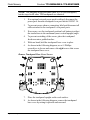
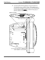
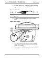
Crestron TPS-MEM64MB & TPS-MEM128MB
Flash Memory for TPS User Interfaces
Installation Guide
This document was prepared and written by the Technical Documentation department at:
Crestron Electronics, Inc.
15 Volvo Drive
Rockleigh, NJ 07647
1-888-CRESTRON
All brand names, product names and trademarks are the property of their respective owners.
©2004 Crestron Electronics, Inc.
Crestron TPS-MEM64MB & TPS-MEM128MB
Flash Memory
Contents
Flash Memory for TPS User Interfaces:
TPS-MEM64MB & TPS-MEM128MB
1
Introduction........................................................................................................1
Features and Functions ..........................................................................1
Physical Description ..............................................................................2
Industry Compliance..............................................................................2
Verifying Installed Memory ..............................................................................2
Local Verification ..................................................................................2
Remote Verification...............................................................................2
Memory Module Expansion Compatibility .......................................................4
Tilt Model Inspection Procedure ...........................................................5
Lectern Model Inspection Procedure .....................................................5
Installation..........................................................................................................5
Tilt Model Installation Procedure ..........................................................5
Lectern Model Installation Procedure..................................................10
Problem Solving...............................................................................................17
Troubleshooting ...................................................................................17
Further Inquiries...................................................................................18
Future Updates .....................................................................................18
Return and Warranty Policies ..........................................................................19
Merchandise Returns / Repair Service.................................................19
CRESTRON Limited Warranty...........................................................19
Installation Guide - DOC. 6261
Contents • i
Crestron TPS-MEM64MB & TPS-MEM128MB
Flash Memory
Flash Memory for TPS User
Interfaces: TPS-MEM64MB &
TPS-MEM128MB
Introduction
Features and Functions
There are two flash memory expansion modules available for select TPS
products: TPS-MEM64MB and TPS-MEM128MB. These memory
modules directly replace the original 16MB memory module that is
supplied with the TPS device. These expansion modules provide
additional flash memory which may be needed to improve performance
when loading/running large and complex programs. These modules also
contain the latest TPS firmware.
NOTE: TPS devices include select TPS touchpanel models and the TPS
touchpanel interface unit (TPS-TPI). For more information, refer to
“Memory Module Expansion Compatibility” on page 4.
Functional Summary
• Direct replacement for factory-installed 16MB flash memory
module found on many TPS products
• Improves performance when loading and running large and
complex programs
• Latest TPS firmware is already installed for access to latest TPS
features
Installation Guide - DOC. 6261
Flash Memory for TPS User Interfaces: TPS-MEM64MB & TPS-MEM128MB • 1
Flash Memory
Crestron TPS-MEM64MB & TPS-MEM128MB
Physical Description
Each memory expansion module is a printed circuit board (PCB)
designed for installation into a specific memory socket on the TPS
device’s motherboard.
Industry Compliance
As of the date of manufacture, the flash memory for TPS user interfaces
has been tested and found to comply with specifications for CE marking
and standards per EMC and Radiocommunications Compliance
Labelling.
NOTE: This device complies with part 15 of the FCC rules. Operation is
subject to the following two conditions: (1) this device may not cause
harmful interference, and (2) this device must accept any interference
received, including interference that may cause undesired operation.
Verifying Installed Memory
If unknown, the total amount of flash memory residing on a given TPS
device can be easily determined. This can be done locally (the device is
within close physical proximity, and not necessarily networked) or
remotely (networked device located over some distance).
Local Verification
Enter the “SETUP MODE” as described in the "Configure the …"
section of the TPS device’s Operations Guide. From the Main Menu,
navigate to the Diagnostics Menu and select the Display Configuration
button. The new screen displays a list of configuration information.
Search for the item titled “Flash Total Size”. The amount of flash
memory residing in the device is shown.
Remote Verification
To remotely view the amount of memory that is installed in a TPS
device, the Crestron Viewport must be used.
2 • Flash Memory for TPS User Interfaces: TPS-MEM64MB & TPS-MEM128MB
Installation Guide - DOC. 6261
Crestron TPS-MEM64MB & TPS-MEM128MB
Flash Memory
NOTE: The Crestron Viewport is available as a pull-down command
from SIMPL Windows and VT Pro-e (Tools | Viewport) or as a
standalone utility. The Viewport utility performs multiple system tasks,
primarily via an RS-232 or TCP/IP connection between the control
system and a PC. It is used to observe system processes, upload new
operating systems and firmware, change system and network parameters,
and communicate with network device consoles and touchpanels, among
many other tasks. Viewport can also function as a terminal emulator for
generic file transfer. All of these functions are accessed through the
commands and options in the Viewport menus. Therefore, for its
effectiveness as a support and diagnostic tool, the Crestron Viewport may
be preferred over development tools when uploading programs and
projects.
NOTE: It is assumed that communications with a Crestron control
system have been established. For instructions on establishing
communications between a PC and a TPS device, refer to the latest
revision of the Operations and Installation Guide for the TPS device.
1. Open the Crestron Viewport.
Either launch the stand-alone version of Viewport, or start
SIMPL Windows or VT Pro-e, and from the menu bar, select
Tools | Viewport.
2. As shown after this step, select Remote | Remote Console |
Connect to open the "Select Network ID" window.
Remote | Remote Console | Connect
3. Enter or scroll down to the ID of the TPS device.
4. Click OK. The TPS> prompt will be displayed in the Viewport
window.
5. At the TPS> prompt, type SHOWHW and press Enter. The
Viewport replies with a list of configuration information.
Installation Guide - DOC. 6261
Flash Memory for TPS User Interfaces: TPS-MEM64MB & TPS-MEM128MB • 3
Flash Memory
Crestron TPS-MEM64MB & TPS-MEM128MB
Search for the item titled “Flash Total Size”. The amount of
flash memory that is installed in the device is shown.
Memory Module Expansion Compatibility
Only select models of the TPS-4500, TPS-5000, TPS-6000, and
TPS-TPI series of TPS devices are compatible with the TPS-MEM64MB
and TPS-MEM128MB flash memory expansion modules. Refer to the
following table for a list of fully compatible models.
TPS Devices Compatible with TPS-MEM64MB and TPS-MEM128MB
PRODUCT
PART NUMBER
TPS-4500
6002378
TPS-4500LB
6002379
TPS-4500LVB
6002381
TPS-4500LVW 6002382
TPS-4500LW
6002380
TPS-5000
6002371
TPS-5000LB
6002372
TPS-5000LW
6002373
TPS-6000
6002374
TPS-6000LB
6002375
TPS-6000LW
6002376
TPS-TPI
6002377
NOTE: Part numbers are printed on labels that can be found on the
bottom of TPS tilt models and on the back of the TPS-TPI and TPS
lectern models.
Other TPS devices with similar product numbers may be compatible with
the TPS-MEM64MB and TPS-MEM128MB. To verify whether a
specific TPS device is compatible with the memory expansion module,
perform one of the following inspection procedures.
4 • Flash Memory for TPS User Interfaces: TPS-MEM64MB & TPS-MEM128MB
Installation Guide - DOC. 6261
Crestron TPS-MEM64MB & TPS-MEM128MB
Flash Memory
Tilt Model Inspection Procedure
Only TPS touchpanels with a jumper for selecting memory voltage are
compatible with the TPS-MEM64MB and the TPS-MEM128MB. To
confirm the presence of the jumper, perform steps 1 through 10 of the
“Tilt Model Installation Procedure” on page 5.
Lectern Model Inspection Procedure
Only TPS devices with a jumper for selecting memory voltage are
compatible with the TPS-MEM64MB and the TPS-MEM128MB. To
confirm the presence of the jumper, perform steps 1 through 5 of the
“Lectern Model Installation Procedure” on page 10.
Installation
CAUTION: Installation of a new memory module results in the loss of
any VT Pro-e project uploaded prior to module replacement. Make sure
that the project has been saved to a PC if the project is to be uploaded
again.
The TPS-MEM64MB and TPS-MEM128MB memory modules are
designed for installation into a specific memory socket on a compatible
TPS device. TPS devices are available in tilt and lectern models. As a
result, the installation procedure for each model differs. The only tools
required for either procedure are a #1 Phillips screwdriver and a
grounding strap (or grounded workstation).
Tilt Model Installation Procedure
CAUTION: The memory module and the TPS tilt-model touchpanel
contain ESD-sensitive devices. Perform the following procedure while
wearing a grounding strap that is properly grounded or on a grounded
workstation to avoid damaging the module and/or the user interface.
NOTE: If the angle of the touchscreen needs to be adjusted, refer to the
latest revision of the touchpanel Operations Guide for instructions of how
to use the touchpanel position lock buttons. The latest version of the
appropriate Operations Guide is available from the Downloads | Product
Manuals section of the Crestron website (www.crestron.com).
Installation Guide - DOC. 6261
Flash Memory for TPS User Interfaces: TPS-MEM64MB & TPS-MEM128MB • 5
Flash Memory
Crestron TPS-MEM64MB & TPS-MEM128MB
NOTE: The diagrams in this procedure show a TPS-5000 touchpanel,
but the steps for all other TPS touchpanels are identical.
1.
If an optional external power pack is utilized, disconnect the
power pack from the touchpanel rear port labeled 24VDC 2A.
2.
To prevent errors when re-connecting, label and disconnect all
cables attached to the touchpanel’s rear panel ports.
3.
If necessary, use the touchpanel position lock buttons to adjust
the touchscreen to the maximum (most vertical/upright) angle.
4.
To prevent scratching of the screen, place the touchpanel
facedown onto a padded surface.
5.
With one hand, hold the touchpanel base cover in place.
6.
As shown in the following diagram, use a #1 Phillips
screwdriver to loosen and remove the eight screws that secure
the touchpanel base cover.
Remove Touchpanel Base Cover Screws
7.
Place the touchpanel upright on the work surface.
8.
As shown in the following diagram, remove the touchpanel
base cover by raising it upwards and rearward.
6 • Flash Memory for TPS User Interfaces: TPS-MEM64MB & TPS-MEM128MB
Installation Guide - DOC. 6261
Crestron TPS-MEM64MB & TPS-MEM128MB
Flash Memory
Remove Touchpanel Base Cover
9.
If installed, remove the TPS-VID-1 or TPS-VID-2 video
expansion card to obtain unobstructed access to the memory
socket, as shown in the following diagram. If there is no video
expansion card, continue with the next step.
TPS-VID-1 / TPS-VID-2 Removal
Installation Guide - DOC. 6261
Flash Memory for TPS User Interfaces: TPS-MEM64MB & TPS-MEM128MB • 7
Flash Memory
Crestron TPS-MEM64MB & TPS-MEM128MB
10. As shown in the following diagram, locate the jumper for
selecting the memory module voltage. If the jumper is not
present on the touchpanel motherboard, the TPS-MEM64MB
and TPS-MEM128MB cannot be installed. If the jumper is
present, continue to the next step.
Jumper Location
LOCATION OF JUMPER FOR
SELECTING VOLTAGE
FOR TPS-MEM-64MB AND TPS-MEM128MB,
MOVE JUMPER TO 3.3V POSITION
8 • Flash Memory for TPS User Interfaces: TPS-MEM64MB & TPS-MEM128MB
Installation Guide - DOC. 6261
Crestron TPS-MEM64MB & TPS-MEM128MB
Flash Memory
11. Move the jumper to the 3.3V position by placing the jumper
over the center pin and the pin labeled 3.3V as shown in the
following diagram.
Jumper in 3.3V Position
NOTE: The memory expansion module will not work if the jumper is in
the “+5V” position.
12. As shown in the following diagram, locate the memory
socket.
Memory Socket Location
NOTE
POLARITY
OF MEMORY
MODULE
(NOTCH IN
CORNER OF SIDE CLIP (ONE
AT EACH END)
BOARD)
LOCATION
OF MEMORY
SOCKET WITH
MEMORY
MODULE
13. Press the two metallic side clips of the socket securing the
original module in opposing directions and notice that the
module lifts up slightly.
14. Use even pressure while backing out the original module out
of the socket.
Installation Guide - DOC. 6261
Flash Memory for TPS User Interfaces: TPS-MEM64MB & TPS-MEM128MB • 9
Flash Memory
Crestron TPS-MEM64MB & TPS-MEM128MB
15. Observe polarity (as shown in the previous illustration) and
insert the new memory module into the socket at a slight
angle.
16. Apply even pressure to the module and level it off, parallel to
the motherboard. The two metallic side clips snap into place
as it becomes seated.
17. If removed, return the TPS-VID-1 or TPS-VID-2 expansion
card.
18. Position the touchpanel base cover onto the base.
19. Hold the touchpanel base cover in place and position the
touchpanel facedown onto a padded surface to prevent
scratching of the screen.
20. Re-install the eight base cover screws to finger-tight then,
using a Philips screwdriver, tighten an additional 1/8-turn.
21. Re-connect all cables to the appropriate ports on the rear of
the touchpanel.
22. If the optional external power pack is utilized, connect the
plug of the power pack to the port labeled 24VDC 2A.
23. Apply power to the touchpanel. If there is no activity, it is
likely that the memory module was improperly replaced.
Repeat the procedure and make sure the jumper for selecting
voltage is in the proper position and that the new module is
properly seated.
Lectern Model Installation Procedure
CAUTION: The memory module and the TPS lectern-model user
interface contain ESD-sensitive devices. Perform the following procedure
while wearing a grounding strap that is properly grounded or on a
grounded workstation to avoid damaging the module and/or the user
interface.
NOTE: The diagrams in this procedure show a TPS-6000L touchpanel.
However, the steps for the TPS-TPI and all other lectern-model TPS
devices are identical. This procedure was written for a TPS device that is
NOT installed into a wall or lectern. If already installed, refer to the latest
revision of the user interface Operations & Installation Guide or, if
10 • Flash Memory for TPS User Interfaces: TPS-MEM64MB & TPS-MEM128MB
Installation Guide - DOC. 6261
Crestron TPS-MEM64MB & TPS-MEM128MB
Flash Memory
applicable, the back box Installation Guide. Disconnect power and
perform the installation procedure in reverse to remove the user interface.
The latest versions of the Operations & Installation Guides are available
from the Downloads | Product Manuals section of the Crestron website
(www.crestron.com).
1.
To prevent scratching of the screen (TPS-TPI excluded), place
the touchpanel facedown onto a padded surface.
2.
As shown in the following diagram, use a #1 Phillips
screwdriver to loosen and remove the 10 screws that secure
the rear cover.
Remove Rear Cover Screws
CAUTION: The connectors of any optional cards that are already
installed may have to be aligned slightly to allow the rear cover to be
removed. Align the connectors carefully to prevent damage to the card,
cover, or unit.
3.
Installation Guide - DOC. 6261
Remove the rear cover as shown in the following diagram by
sliding it towards the bottom of the device.
Flash Memory for TPS User Interfaces: TPS-MEM64MB & TPS-MEM128MB • 11
Flash Memory
Crestron TPS-MEM64MB & TPS-MEM128MB
Remove Rear Cover
4.
To obtain unobstructed access to the memory socket, remove
the expansion cover plate or if previously installed, the
TPS-VIDL-1 or TPS-VIDL-2 video expansion card. Each
procedure is defined in the following sub-steps.
4a. If the expansion cover plate is present, refer to the
following diagram. Using a #1 Phillips screwdriver,
loosen and remove the two screws that secure the
expansion cover plate and remove the plate.
12 • Flash Memory for TPS User Interfaces: TPS-MEM64MB & TPS-MEM128MB
Installation Guide - DOC. 6261
Crestron TPS-MEM64MB & TPS-MEM128MB
Flash Memory
Remove Expansion Cover Plate
4b. If a TPS-VIDL-1 or TPS-VIDL-2 video expansion card
is present, refer to the following diagram. Completely
loosen the knurled mounting screws and carefully
remove the expansion card from the device’s
motherboard connector without bending any of the pins
on the device’s interface connector.
TPS-VIDL-1/TPS-VIDL-2 Removal
Installation Guide - DOC. 6261
Flash Memory for TPS User Interfaces: TPS-MEM64MB & TPS-MEM128MB • 13
Flash Memory
Crestron TPS-MEM64MB & TPS-MEM128MB
5.
As shown in the following diagram, locate the jumper for
selecting memory module voltage. If the jumper is not present
on the device’s motherboard, the TPS-MEM64MB and TPSMEM128MB cannot be installed. If the jumper is present,
continue to the next step.
Jumper Location
FOR TPS-MEM-64MB AND TPS-MEM128MB, MOVE
JUMPER TO 3.3V POSITION
LOCATION OF JUMPER FOR SELECTING VOLTAGE
CRESTRON ELECTRONICS INC.
ROCKLEIGH, NJ 07647 USA
+
S
S
R+
RL+
LS
AUDIO INPUT MIC OUT
NET
24 Y Z G
RS-232
6.
Move the jumper to the 3.3V position by placing the jumper
over the center pin and the pin labeled 3.3V as shown in the
following diagram.
14 • Flash Memory for TPS User Interfaces: TPS-MEM64MB & TPS-MEM128MB
Installation Guide - DOC. 6261
Crestron TPS-MEM64MB & TPS-MEM128MB
Flash Memory
Jumper in 3.3V Position
NOTE: The memory expansion module will not work if the jumper is in
the “+5V” position.
7.
As shown in the following diagram, locate the memory
socket.
Memory Socket Location
SIDE CLIP
(ONE AT
EACH END)
CRESTRON ELECTRONICS INC.
ROCKLEIGH, NJ 07647 USA
LOCATION
OF MEMORY
SOCKET
WITH
MEMORY
MODULE
+
S
S
R+
RL+
LS
AUDIO INPUT MIC OUT
NET
24 Y Z G
RS-232
NOTE
POLARITY
OF MEMORY
MODULE
(NOTCH IN
CORNER OF
BOARD)
8.
Press the two metallic side clips of the socket securing the
original module in opposing directions and notice that the
module lifts up slightly.
9.
Use even pressure while backing out the original module out
of the socket.
10. Observe polarity (as shown in the previous illustration) and
insert the new memory module into the socket at a slight
angle.
11. Apply even pressure to the module and level it off, parallel to
the motherboard. The two metallic side clips snap into place
as it becomes seated.
Installation Guide - DOC. 6261
Flash Memory for TPS User Interfaces: TPS-MEM64MB & TPS-MEM128MB • 15
Flash Memory
Crestron TPS-MEM64MB & TPS-MEM128MB
12. Return the expansion cover plate or TPS-VIDL expansion
card.
CAUTION: If the expansion card is present, the TPS-VIDL connectors
may have to be aligned slightly to fit through the openings in the rear
cover. Align the connectors of this card (or any other optional card that is
installed) carefully to prevent damage to the card, cover, or touchpanel.
13. Install the rear cover by sliding it over any expansion card
connectors that may be present.
14. Re-install the ten cover screws to finger-tight then, using a
#1 Philips screwdriver, tighten the mounting screws an
additional 1/8-turn to secure the cover.
15. Apply power to the unit. If there is no activity, it is likely that
the memory module was improperly replaced. Repeat the
procedure and make sure the jumper for selecting voltage is in
the proper position and that the new module is properly
seated.
16 • Flash Memory for TPS User Interfaces: TPS-MEM64MB & TPS-MEM128MB
Installation Guide - DOC. 6261
Crestron TPS-MEM64MB & TPS-MEM128MB
Flash Memory
Problem Solving
Troubleshooting
The following table provides corrective action for possible trouble
situations. If further assistance is required, please contact a Crestron
customer service representative.
TPS-MEM64MB & TPS-128MB Troubleshooting
TROUBLE
POSSIBLE
CAUSE(S)
CORRECTIVE ACTION
Touchpanel
does not
operate after
replacement.
Improper
connection;
module
improperly
installed.
Module installed
with reverse
polarity.
Follow installation procedures
in this guide.
Damaged
memory module.
Inspect module. If damaged,
contact Crestron customer
service.
Voltage jumper in
incorrect position.
Move jumper to 3.3V position.
Device
configuration
information
does not show
updated
memory
value.
Installation Guide - DOC. 6261
Remove the device cover and
inspect module. Reverse
polarity if necessary.
Flash Memory for TPS User Interfaces: TPS-MEM64MB & TPS-MEM128MB • 17
Flash Memory
Crestron TPS-MEM64MB & TPS-MEM128MB
Further Inquiries
If you cannot locate specific information or have questions after
reviewing this guide, please take advantage of Crestron's award winning
customer service team by calling the Crestron corporate headquarters at
1-888-CRESTRON [1-888-273-7876]. For assistance in your local time
zone, refer to the Crestron website (www.crestron.com) for a listing of
Crestron worldwide offices.
You can also log onto the online help section of the Crestron website
(www.crestron.com) to ask questions about Crestron products. Firsttime users will need to establish a user account to fully benefit from all
available features.
Future Updates
As Crestron improves functions, adds new features, and extends the
capabilities of the TPS memory modules, additional information may be
made available as manual updates. These updates are solely electronic
and serve as intermediary supplements prior to the release of a complete
technical documentation revision.
Check the Crestron website (www.crestron.com) periodically for manual
update availability and its relevance. Updates are available from the
Downloads | Product Manuals section and are identified as an
“Addendum” in the Download column.
18 • Flash Memory for TPS User Interfaces: TPS-MEM64MB & TPS-MEM128MB
Installation Guide - DOC. 6261
Crestron TPS-MEM64MB & TPS-MEM128MB
Flash Memory
Return and Warranty Policies
Merchandise Returns / Repair Service
1.
No merchandise may be returned for credit, exchange, or service without prior authorization
from CRESTRON. To obtain warranty service for CRESTRON products, contact the factory
and request an RMA (Return Merchandise Authorization) number. Enclose a note specifying
the nature of the problem, name and phone number of contact person, RMA number, and
return address.
2.
Products may be returned for credit, exchange, or service with a CRESTRON Return
Merchandise Authorization (RMA) number. Authorized returns must be shipped freight
prepaid to CRESTRON, 6 Volvo Drive, Rockleigh, N.J., or its authorized subsidiaries, with
RMA number clearly marked on the outside of all cartons. Shipments arriving freight collect
or without an RMA number shall be subject to refusal. CRESTRON reserves the right in its
sole and absolute discretion to charge a 15% restocking fee, plus shipping costs, on any
products returned with an RMA.
3.
Return freight charges following repair of items under warranty shall be paid by CRESTRON,
shipping by standard ground carrier. In the event repairs are found to be non-warranty, return
freight costs shall be paid by the purchaser.
CRESTRON Limited Warranty
CRESTRON ELECTRONICS, Inc. warrants its products to be free from manufacturing defects in
materials and workmanship under normal use for a period of three (3) years from the date of purchase
from CRESTRON, with the following exceptions: disk drives and any other moving or rotating
mechanical parts, pan/tilt heads and power supplies are covered for a period of one (1) year;
touchscreen display and overlay components are covered for 90 days; batteries and incandescent lamps
are not covered.
This warranty extends to products purchased directly from CRESTRON or an authorized CRESTRON
dealer. Purchasers should inquire of the dealer regarding the nature and extent of the dealer's warranty,
if any.
CRESTRON shall not be liable to honor the terms of this warranty if the product has been used in any
application other than that for which it was intended, or if it has been subjected to misuse, accidental
damage, modification, or improper installation procedures. Furthermore, this warranty does not cover
any product that has had the serial number altered, defaced, or removed.
This warranty shall be the sole and exclusive remedy to the original purchaser. In no event shall
CRESTRON be liable for incidental or consequential damages of any kind (property or economic
damages inclusive) arising from the sale or use of this equipment. CRESTRON is not liable for any
claim made by a third party or made by the purchaser for a third party.
CRESTRON shall, at its option, repair or replace any product found defective, without charge for parts
or labor. Repaired or replaced equipment and parts supplied under this warranty shall be covered only
by the unexpired portion of the warranty.
Except as expressly set forth in this warranty, CRESTRON makes no other warranties, expressed or
implied, nor authorizes any other party to offer any warranty, including any implied warranties of
merchantability or fitness for a particular purpose. Any implied warranties that may be imposed by law
are limited to the terms of this limited warranty. This warranty statement supercedes all previous
warranties.
Trademark Information
All brand names, product names, and trademarks are the sole property of their respective owners. Windows is a registered
trademark of Microsoft Corporation. Windows95/98/Me/XP and WindowsNT/2000 are trademarks of Microsoft Corporation.
Installation Guide - DOC. 6261
Flash Memory for TPS User Interfaces: TPS-MEM64MB & TPS-MEM128MB • 19
Crestron Electronics, Inc.
15 Volvo Drive Rockleigh, NJ 07647
Tel: 888.CRESTRON
Fax: 201.767.7576
www.crestron.com
Operations Guide - DOC. 6261
04.04
Specifications subject to
change without notice.