1
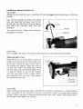
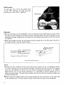
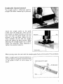
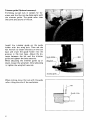
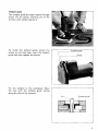
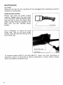
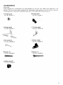
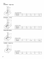
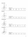
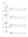
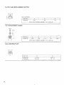
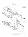
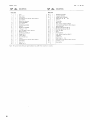
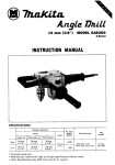
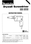
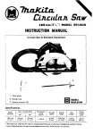
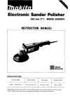
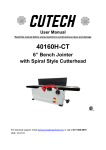
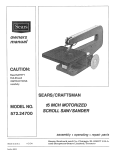
Trimmer
1/4" MODEL 3705
INSTRUCTION MANUAL
DOUBLE
INSULATION
SPEC IFICAT IONS
Collet chuck
capacity
1 4 '
1
No load speed
(RPM)
Overall length
Net weight
23,000
2 1 5 mm ( 8 7 / 1 6 " )
1 8 k g ( 4 Ibs)
IMPORTANT
SAFETY INSTRUCTIONS
(For All Tools)
WARNING: WHEN USING ELECTRIC TOOLS, BASIC SAFETY PRECAUTIONS SHOULD ALWAYS BE FOLLOWED TO
REDUCE THE RISK OF FIRE, ELECTRIC SHOCK, AND PERSONAL INJURY, INCLUDING THE FOLLOWING:
READ ALL INSTRUCTIONS.
1. KEEP WORK AREA CLEAN. Cluttered areas and benches invite injuries.
2. CONSIDER WORK AREA ENVIRONMENT. Don't use power tools in damp
or wet locations. Keep work area well lit. Don't expose power tools t o rain.
Don't use tool in presence of flammable liquids or gases.
3. KEEP CHILDREN AWAY. All visitors should be kept away from work area.
Don't let visitors contact tool or extension cord.
4.STORE IDLE TOOLS. When not in use, tools should be stored in dry, and high
or locked-up place - out of reach of children.
5. DON'T FORCE TOOL. It will do the job better and safer at the rate for which
it was intended.
6 . USE RIGHT TOOL. Don't force small tool or attachment t o do the job of a
heavy-duty tool. Don't use tool for purpose not intended.
7. DRESS PROPERLY. Don't wear loose clothing or jewelry. They can be caught
in moving parts. Rubber gloves and n o n s k i d footwear are recommended
when working outdoors. Wear protective hair covering t o contain long hair.
8 . USE SAFETY GLASSES. Also use face or dust mask if cutting operation is
dusty.
9 . DON'T ABUSE CORD. Never carry tool by cord or yank it t o disconnect from
receptacle. Keep cord from heat, oil, and sharp edges.
IO. SECURE WORK. Use clamps or a vise t o hold work. It's safer than using
your hand and it frees both hands t o operate tool.
11. DON'T OVERREACH. Keep proper footing and balance at all times.
12. MAINTAIN TOOLS WITH CARE. Keep tools sharp and clean for better and
safer performance. Follow instructions for lubricating and changing accessories. Inspect tool cords periodically and if damaged, have repaired by authorized service facility. Inspect extension cords periodically and replace if
damaged. Keep handles dry, clean, and free from oil and grease.
13. DISCONNECT TOOLS. When not i n use, before servicing, and w h e n changing accessories, such as blades, bits, cutters.
14. REMOVE ADJUSTING KEYS AND WRENCHES. Form habit of checking t o
see that keys and adjusting wrenches are removed f r o m tool before turning
it on.
15. AVOID UNINTENTIONAL STARTING. Don't carry plugged-in tool with finger
on switch. Be sure switch is OFF w h e n plugging in.
16. OUTDOOR USE EXTENSION CORDS. When tool is used outdoors, use only
extension cords intended for use outdoors and so marked.
17. STAY ALERT. Watch what you are doing, use common sense. Don't operate
tool w h e n you are tired.
18. CHECK DAMAGED PARTS. Before further use of the tool, a guard or other
part that is damaged should be carefully checked t o determine that it will
operate properly and perform i t s intended function. Check for alignment of
moving parts, binding of moving parts, breakage of parts, mounting, and
any other conditions that may affect its operation. A guard or other part
that is damaged should be properly repaired or replaced by an authorized
service center unless otherwise indicated elsewhere in this instruction
manual. Have defective switches replaced by authorized service center. Don't
use tool if switch does not turn it on and off.
19. GUARD AGAINST ELECTRIC SHOCK. Prevent body contact with grounded
surfaces. For example; pipes, radiators, ranges, refrigerator enclosures.
20. REPLACEMENT PARTS. When servicing, use only identical replacement parts.
21. POLARIZED PLUGS. To reduce the risk of electric shock, this equipment has
a polarized plug (one blade is wider than the other). This plug will f i t in a
polarized outlet only one way. If the plug does not f i t fully in the outlet,
reverse the plug. If it still does not fit, contact a qualified electrician t o install
the proper outlet. D o not change the plug i n any way.
.
VOLTAGE WARNING: Before connecting the tool t o a power source (receptacle,
outlet, etc.) be sure the voltage supplied is the same as that specified on the
nameplate of the tool. A power source with voltage greater than that specified
for the tool can result in SERIOUS INJURY t o the user - as well as damage t o
the tool. If i n doubt, DO NOT PLUG IN THE TOOL. Using a power source with
voltage less than the nameplate rating is harmful t o the motor.
ADDITIONAL SAFETY RULES
1. Wear hearing protection during extended periods of operation.
2. Handle the bits very carefully.
3. Check the bit carefully for cracks or damage before operation.
Replace cracked or damaged bit immediately.
4. Avoid cutting nails. Inspect for and remove all nails from the workpiece
before operation.
5. Hold the tool firmly.
6. Keep hands away from rotating parts.
7. Make sure the bit is not contacting the workpiece before the switch is turned
On.
8. Before using the t o o l on an actual workpiece, let it run for a while.
Watch for vibration or wobbling that could indicate improperly installed bit.
9. Be careful of the b i t rotating direction and the feed direction.
IO. Do not leave the t o o l running. Operate the tool only when hand-held.
11. Always switch off and wait for the bit t o come t o a complete stop before
removing the tool from workpiece.
12. Do not touch the bit immediately after operation; it may be extremely hot
and could burn your skin.
13. Don’t smear the t o o l base carelessly w i t h thinner, gasoline, oil or the like.
They may cause cracks i n the tool base.
SAVE THESE INSTRUCTIONS.
A
Installing or removing trimmer bit
CAUTION :
Always be sure that the tool i s switched off and unplugged before installing or removing
the bit.
Use the hex wrench to loosen the clamp
bolt and lower the tool base. lnser the bit
a l l the way into the collet cone and tighten
the collet nut securely with the two
wrenches.
To remove the bit, follow the installation
procedure in reverse.
CAUTION :
Do not tighten the collet nut without inserting a bit, or the collet cone will break.
Adjusting depth of cut
Place the tool on a fiat surface. Loosen the
clamp bolt and move the tool body until
the bit just touches the flat surface. Tighten
the clamp bolt slightly. Place the tool on
i t s side and loosen the clamp bolt. Move
the tool base until the desired depth of cut
i s obtained. Depth of cut can be checked
with the scale label ( 1 mm or about 3/64"
per graduation) on the tool. Then tighten
the clamp bolt securely.
Bit protrusion
2
Clamp bolt
CAUTION :
Since excessive cutting may cause overload of the motor or difficulty in controlling the
tool, the depth of cut should not be more than 3 mm (1/8") a t a pass when cutting
grooves. When you wish to cut grooves more than 3 mm (1/8") deep, make several passes
with progressively deeper bit settings.
Switch action
To start the tool, move the switch lever
to the “ON” position. To stop, move the
switch lever to the “OFF” position.
Operation
*Set the tool base on the workpiece to be cut without the bit making any contact. Then
turn the tool on and wait until the bit attains full speed. Move the tool forward over the
workpiece surface, keeping the tool base flush and advancing smoothly until the cutting
is complete.
0
When doing edge cutting, the workpiece surface should be on the left side of the bit in
the feed direction. (See the figure below)
”
:;;eB:w
Feed direction
/ / / / / / / / / I ,‘/
(View f r o m the tip o f the tool)
,//,/
I
Correct b i t feed direction
NOTE :
Moving the tool forward too fast may cause a poor quality of cut, or damage to the bit
or motor. Moving the tool forward too slowly may burn and mar the cut. The proper
feed rate will depend on the bit size, the kind of workpiece and depth of cut. Before
beginning the cut on the actual workpiece, it i s advisable to make a sample cut on a
piece of scrap lumber. This will show exactly how the cut will look as well as enable you
t o check dimensions.
When using the straight guide or the trimmer guide, be sure to install it on the right side
in the feed direction. This will help to keep i t flush with the side of the workpiece.
0
6
Straight guide (Optional accessory)
The straight guide is effectively used for
straight cuts when chamfering or grooving.
Install the straight guide on the guide
holder with the wing bolt. Then use the
hex wrench to loosen the bolts on the tool
base and insert the guide holder into the
grooves in the tool base. Adjust the distance between the bit and the straight
guide and tighten the bolts securely. When
adjusting the straight guide up or down,
loosen the wing bolt. After adjusting it,
tighten the wing bolt securely.
I
Guide holder
\
When cutting, move the tool with the straight guide flush with the side of the workpiece.
Wider straight guide of desired dimensions
may be made by using the convenient holes
in the guide to bolt on extra pieces of
wood.
7
Trimmer guide (Optional accessory)
Trimming, curved cuts in veneers for furniture and the like can be done easily with
the trimmer guide. The guide roller rides
the curve and assures a fine cut.
Install the trimmer guide on the guide
holder with the wing bolt. Then use the
hex wrench to loosen the bolts on the tool
base and insert the guide holder into the
grooves in the tool base. Adjust the distance between the bit and the trimmer
guide and tighten the bolts securely.
When adjusting the trimmer guide up or
down, loosen the wing bolt. After adjusting
it, tighten the wing bolt securely.
Trimmer guide
/
When cutting, move the tool with the guide
roller riding the side of the workpiece.
I kBit
roller
x
Templet guide
The templet guide provides a sleeve through
which the bit passes, allowing use of the
trimmer with templet patterns.
To install the templet guide, loosen the
screws on the tool base, insert the templet
guide and then tighten the screws.
Fix the templet to the workpiece. Move
the tool with the templet guide sliding
along the side of the templet.
Templet guide
7
I
Bitk
y t n p l e t guide
MAINTENANCE
CAUTION :
Always be sure that the tool is switched off and unplugged before attempting to perform
inspection or maintenance.
Replacing carbon brushes
Remove and check the carbon brushes
regularly. Replace when they wear down
to the limit mark. Keep the carbon brushes
clean and free t o slip in the holders. Both
carbon brushes should be replaced a t the
same time. Use only identical carbon
brushes.
Use a screwdriver to remove the brush
holder caps. Take out the worn carbon
brushes, insert the new ones and secure the
brush holder caps.
To maintain product SAFETY and RELIABILITY, repairs, any other maintenance or
adjustment should be performed by Makita Authorized or Factory Service Centers,
always using Makita replacement parts.
IO
ACCESSORIES
CAUTION :
These accessories or attachments are recommended for use with your Makita tool specified in this
manual. The use of any other accessories or attachments might present a risk of injury t o persons.
The accessories or attachments should b e used only in the proper and intended manner.
0
0
0
0
Templet guide
Guide holder
Part No. 321912-7
Part No. 122281-7
Straight guide
Part No. 341947-2
0
Trimmer guide
Part No. 16316 2 - 6
Hex wrench 6
0
Part No. 783204-6
Wrench holder
Part No. 410047-0
Wrench 10
Wrench 17
Part No. 781003-0
Part No. 781008-0
Collet cone 1/4"
Part No. 763608-8
Bits
STRAIGHT - Single Flute
HIGH SPEED STEEL
STRAIGHT
P A R T NO.
A
B
C
D
E
733232-6A
118
5/16
1.118
1/ 4
1-518
- 2 Flute
iDi-
CARBIDE TIPPED
P A R T NO.
A
B
C
D
E
733003-2A
3/16
7116
1-318
114
2
HINGE MORTISING
C A R B I D E TIPPED
I
VEINING
PARTNO.
A
B
C
D
E
733006-9A
112
112
1-1116
114
1-13116
- Single Flute
SOLID CARBIDE
I2
P A R T NO.
A
B
C
D
E
733007-8A
3116
7/32
1-1I 4
114
1-112
ROUND NOSE
CARBIDE TIPPED
P A R T NO.
A
B
C
D
E
733008-2A
733008-4A
114
318
15132
9116
1 ~I 14
1-114
114
114
1-718
2
CORE BOX
HIGH SPEED STEEL
P A R T NO.
A
8
C
D
E
733238-2A
1I4
114
1-3116
1I 4
1-1/ 2
VEE GROOVING
-pr
CARBIDE TIPPED
I
PARTNO
733009-2A
733009~4A
A
8
C
D
E
0
318
518
112
314
1.3116
15/16
114
114
2
2
9 0"
90"
1
14" DOVETAIL
4 D k -
C A R B I D E TIPPED
P A R T NO.
A
B
C
D
733009-6A
112
1/2
1-114
114
E
1~718
13
PANEL PILOT
H I G H SPEED STEEL
PART NO
A
B
C
D
E
733236 OA
114
314
1
114
2 7116
CORNER ROUNDING
HIGH SPEED STEEL
PARTNO
733240 2A
Solid Pilof
B
C
D
E
R
112
1
114
1 314
114
AI
A,
11/16
3/16
COVE
H I G H SPEED STEEL - Solid Pilot
FLUSH TRIMMER
PARTNO.
A)
A2
6
C
D
E
R
733242-6A
11116
3/16
112
1
114
1-314
114
- Self Piloting
SOLID CARBIDE
PART
NO
733128 OA
14
A
B
C
D
E
114
114
1 1116
1I 4
19/16
7" BEVEL TRIMMER
- Self-Piloting
PART NO
A
B
C
D
E
7331 28 2A
3116
114
11/16
114
19/16
2 F L U T E FLUSH TRIMMER
CARBIDE TIPPED
P A R T NO
A
B
C
D
E
7331 28-9A
1/ 2
112
1114
114
2-1/16
REPLACEMENT B E A R I N G
~
NO 733132-4A
COMBINATION FLUSH/22" BEVEL TRIMMER
ilJk
CARBIDE TIPPED
P A R T NO
A
BI
82
C
D
E
733128 6A
7/16
112
3/16
1 114
1/4
1 314
3 F L U T E FLUSH TRIMMER ASSEMBLY -Self Piloting
-!lb
SOLID CARBIDE CUTTER
-______.
.
PART NO
A
B
C
0
E
733129 2A
5/8
3i8
1114
1/4
2318
REPLACEMENT BEARING
~
NO 733132 6 A
1
I
15
FLUTE FLUSH REPLACEMENT CUTTER
SOLID CARBIDE
PART NO.
A
B
D
733129-6A
5/8
318
114
I
FOR FLUSH TRIMMER ASSEMBLY NO. 733129-2A
114" REPLACEMENT ARBOR
I
I
PARTNO
A
B
C
D
E
733131-2A
518
318
1-114
114
2-318
I
FOR FLUSH TRIMMER ASSEMBLY NO 733129-2A
l
I
I
BALL BEARING PILOT
I
16
PARTNO
D,
D7
733132-4A
733132 6A
112 O D
518 0 D
3/16 I D
114 I D
I
oct
09
87
us
114"
TRIMMER
Model 3705
Note The switch, noise suppressor and other part configurations
may differ from country to country
17
Mar
MODEL 3705
",;I
,!&
DESCRIPTION
M A C E
1
2
4
5
6
1
MACHINE
Clirrl
Redr Cover
28
2
Curd Guard
Pan Head Srrew M 4 x 1 4 IWifh WazhPrl
29
30
31
32
33
34
1
Strain Relipf
1
1
9
1
10
1
1
M o m Redr t l o w n g
FIELD ASSEMBLY
Drsvr S h a l l
Ball Bearing 6 0 0 0 L B
Ring 10
Ball Bedrinq 6000LB
v Pulley 3 19
Hex Bolt M 4 x 1 0 IWtfh Wdahcrl
M o m Houz~nq
Ball Bearing 6200LLB
Rubber Pin 4
Carbon 8 r " a l l
Brush Holder C a l i
sw,,,.t,
Pdn Head S ~ r u wM 4 x 4 0 lWirh W a s h r i l
Name Pial?
Rivet 0 5
Rubber Pin 4
12
13
1
14
15
2
1
16
I7
18
19
1
1
2
2
1
11
1
22
23
3
1
2
1
24
25
26
27
1
1
7
8
11
-
DESCRIPTION
35
36
31
38
39
40
41
42
1
1
1
1
1
1
1
1
1
4
2
2
Ball Bearinq 627L8
l n ~ u l a t i o nWasher
ARMATURE ASSEMBLY
IWith Item 16 26
291
Fdn 52
Torsmn Bar
Belt Cover
Hex Socket Head Boll M a x 1 1
Pan Head Screw M 4 x 1 4 l W i l h WarhPrl
Base Protector
Binding Head Screw M 4 x 1 2
Binding Head Screw M a r 1 6
Hex Nul M 8
1
Base
2
Flat Washer 8
2
1
Hex Socket Head Boll Max12
1
43
1
44
45
46
2
1
1
- -
Note The switch and other part specIfIca1~onsm a y d i f f e r from country t o ( o u n l r y
Collel Nul
Collel c o n e
P O I " v Bell 3
170
Pan Head Screw M 4 r 1 8 I W i l h Wdsherl
V Pulley 3 2 3
Bearing Box
31 86 US
MAKITA LIMITED ONE YEAR WARRANTY
Warranty Policy
Every Makita tool is thoroughly inspected and tested before leaving the factory. It is warranted t o
be free of defects from workmanship and materials for the period of ONE YEAR from the date of
original purchase. Should any trouble develop during this one-year period, return the COMPLETE
tool, freight prepaid, t o one of Makita’s Factory or Authorized Service Centers. If inspection shows
the trouble is caused by defective workmanship or material, Makita will repair (or at our option,
replace) without charge.
This Warranty does not apply where:
repairs have been made or attempted by others:
repairs are required because of normal wear and tear:
The tool has been abused, misused or improperly maintained;
alterations have been made t o the tool.
IN NO EVENT SHALL MAKITA BE LIABLE FOR ANY INDIRECT, INCIDENTAL OR CONSEQUENTIAL DAMAGES FROM THE SALE OR USE O F THE PRODUCT. THIS DISCLAIMER
APPLIES BOTH DURING AND AFTER THE TERM O F THIS WARRANTY.
MAKITA DISCLAIMS LIABILITY FOR ANY IMPLIED WARRANTIES, INCLUDING IMPLIED
WARRANTIES O F “MERCHANTABILITY” AND “FITNESS FOR A SPECIFIC PURPOSE,”
AFTER THE ONE-YEAR TERM O F THIS WARRANTY.
This Warranty gives you specific legal nghts, and you may also have other rights which vary from
state to state. Some states d o not allow the exclusion or limitation of incidental or consequential
damages, so the above limitation or exclusion may not apply to you. Some states d o not allow
limitation on how long an implied warranty lasts, so the above Limitation may not apply to you.
Makita Corporation
3-11-8, Sumiyoshi-cho,
Anjo, Aichi 446 Japan
883497D068
PRINTED IN JAPAN
1992 - 8 - N