1
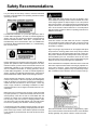
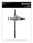
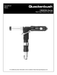
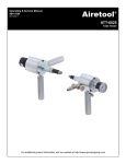
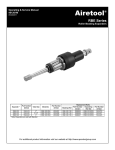
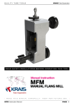
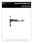
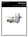
Operating & Service Manual
90093-IM
05/11/2011
Airetool
®
CC-325-HP
High Pressure Water Flush Condenser Tube Cleaner
For additional product information visit our website at http://www.apextoolgroup.com
Safety Recommendations
For your safety and the safety of others, read and understand
the safety recommendations and operating instructions before
operating an Airetrol.
When using right angle Airetrols, be sure the throttle is positioned relative to the angle head so that the throttle will not become wedged against an adjacent object in the “ON” position
due to torque reaction. The angle head may be repositioned with
respect to the lever to accomodate proper location for the task. If
tool is to be reversed, locate throttle lever in a neutral position
that will prevent entrapment. Refer to operating instructions for
additional information.
For additional information on eye and face protection, refer to
Federal OSHA Regulations, 29 Code of Federal Regulations,
Section 1910.133., Eye and Face Protection, and the American
National Standards Institute, ANSI A87.1, Occupational and
Educational Eye and Face Protection. Z87.1 is available from
the American National Standards Institute, Inc., 1430 Broadway,
New York, NY 10018.
Tools with clutches can stall rather than shut-off if adjusted
over the maximum power output of the tool, or if there is a drop
in air pressure. Operator must then resist the stall torque until
the throttle is released.
Higher torque right angle Airetrols can be equipped with spline
torque reaction mounting plates which accept torque reaction
bars. These bars can be braced against the work or other suitable points to absorb and relieve the operator of the torque reaction transmitted by the tool. Tool balance arms are also available to absorb the torque reaction of the tool while balancing the
weight of the tool for improved ergonomic applications.
Hearing protectors are required in high noise areas, 85 dBA or
greater. The operation of other tools and equipment in the area,
reflective surfaces, process noises and resonant structures can
substantially contribute to, and increase the noise level in an
area. For additional information on hearing protection, refer to
Federal OSHA Regulations, 29 Code of Federal Regulations,
Section 1910.95, Occupational Noise Exposure, and American
National Standards Institute, ANSI S12.6 Hearing Protectors.
Some individuals are susceptible to disorders of the hands and
arms when exposed to tasks which involve highly repetitive motions and/or vibration. Those individuals predisposed to
vasculatory or circulatory problems may be particularly susceptible. Cumulative trauma disorders such as carpal tunnel syn-
Airetool Airetrols are designed to operate on 90 psig (6.2 bar)
maximum air pressure. If the tool is properly sized and applied,
higher air pressure is unnecessary. Excessive air pressure increases the load and stresses on the tool parts, which may
result in cage, mandrel or roll breakage. Installation of a filterregulator-lubricator in the air supply line ahead of the tool is recommended.
Before the tool is connected to the air supply, check the throttle
for proper operation (i.e., throttle moves freely and returns to the
closed position). Clear the air hose of accumulated dust and
moisture. Be careful not to endanger adjacent personnel. Before removing a tool from service or changing sockets, make
sure the air line is shut off and drained of air. This will prevent
the tool from operating if the throttle is accidently engaged.
It is essential for the safe operation that the operator of an Airetrol use good balance, sure footing, and proper posture in anticipation of the torque reaction. Insure that the operator’s hand will
not be wedged or pinched between the work and the tool when
operating.
drome and tendonitis can be caused or aggravated by repetitious, forceful exertions of the hands and arms. These disorders
develop gradually over periods of weeks, months and years.
2
Safety Recommendations
ADDITIONAL SAFETY RECOMMENDATIONS FOR USE
OF RIGHT ANGLE AIRETROLS
* Tasks should be performed in such manner that the wrists
are maintained in a neutral position, which is not flexed,
hyperextended, or turned side to side.
* Stressful postures should be avoided and can be controlled
through tool selection and work location.
Any user suffering from prolonged symptoms of tingling, numbness, blanching of fingers, clumsiness or weakened grip, nocturnal pain in the hand, or any other disorder of the shoulders,
arms, wrists, or fingers is advised to consult with a physician. If
it is determined that the symptoms are job related or aggravated
by movements and postures indicated by the job design it may
be necessary for the employer to take steps to prevent further
occurrences. These steps might included, but are not limited to,
repositioning the work piece or redesigning the workstation, reassigning workers to the jobs, rotating jobs, altering work pace,
and/or changing the type of tool used so as to minimize stress
on the operator. Some tasks may require more than one type of
tool to obtain the optimum operator/tool/task relationship.
Follow good machine shop practices. Rotating shafts and components can entangle and enwrap, and can result in serious injures. Never wear long hair, loose-fitting clothes, gloves, ties, or
jewelry when working with or near a drill or any machine with
exposed rotating shaft.
Drilling or other use of this tool may produce hazardous fumes,
particles, and/or dust. To avoid adverse health effects utilize
adequate ventilation and/or a respirator. Read the material safety
data sheet of any cutting fluids or materials involved in the drilling process.
The following recommendations will help reduce or moderate
the effects of repetitive work motions and/or extended vibration
exposure:
* Use a minimum hand grip force consistent with proper control
and safe operation.
* Keep wrists as straight as possible.
* Keep body and hands warm and dry.
* Drill bits are sharp, handle them carefully to avoid injury. The
cutting tool maximum speed rating must equal or exceed the
rated speed of the tool.
* Avoid anything that inhibits blood circulation.
- Smoking Tobacco
- Cold Temperatures
- Certain Drugs
* Attach the mandrel and the chuck securely to the Airetrol to
prevent tool from jumping off work.
* Use precautions when drilling because of the possibility of the
cutting tool bending or breaking.
* Avoid highly repetitive movements of hands and wrists, and
continuous vibration exposure.
* High reaction torque may be experienced by the operator when
reversing tool to remove the expander.
* Drill bits or accessories not centered properly in the chuck can
cause excessive wobble or vibration.
3
Operating & Service Instructions
CC-325-HP High Pressure Water Flush
Condenser Cleaner Motor
SPECIFICATIONS
FLUSHING AGENT
Recommended Air Pressure - 90/100 psi.
Air Volume Required - 200 cfm.
Minimum Hose Size - 1” I. D.
Air Line Lubricator - 15/20 Drops Per Minute (10W Oil)
Maximum Flushing Pressure - 5000 psi (water/scavenging
Agent)
Approximate Peak Power - 6 hp.
The model CC-325-HP condenser cleaner motor coupling
as installed upon this machine is designed to operate with
(6000 psi) pressure water or scavenging agent to assist
the mechanical cleaning action of the drill bits in condenser
tubing and similar applications. The water supply hose and
couplings, NOT SUPPLIED WITH THE TOOL, should only
be of a recommended type to withstand this amount of pressure. Lower pressure may also be used with this supply
hose. The CC-325-HP uses standard Airetool condenser
cleaner shafting and couplings but requires the use of the
Airetool Model “ HP” condenser cleaner drills for best results. SEE PAGE 13 FOR SELECTION. If the tool is to be
run for extended periods without using water or other scavenging agent, The packing gland nut can be temporarily
loosened or the packing removed to avoid damage to the
packing. The packing should be kept well lubricated.
MODEL #
CC-325-HP
Weight
42 lbs.
Free Speed
800 rpm
Torque Capacity
63 ft-lbs.
OPERATING INSTRUCTIONS
AIR SUPPLY
To use the CC-325-HP cleaner, it is necessary to use a
compressor with a capacity to supply a sustained air pressure of 90 psi at 200 cfm. It is therefore necessary to use a
air supply hose with a 1” I. D. in order to be sure in having
an adequate volume to the tool. It should also be noted
that long hose runs, air hose quick connects, fittings, etc.
can cause large pressure drops between the tool and the
compressor and that is many cases, poor tool performance
can be improved by minimizing these conditions and/or increasing the air line size (ID).
USING THE CC-325-HP CONDENSER
CLEANER
The CC-325-HP condenser cleaner can be used with lower
pressure on the scavenging agent satisfactorily, however,
maximum cleaning is done with pressure at 5000 psi. When
connecting the water connections and the shafting to the
cleaner, CAUTION should be taken to make sure that all
joints are tightened properly to prevent the possibility of
leakage of the high pressure. It is recommended that the
water be shut off when the drill bit is not inside the tube to
prevent the possibility of contacting someone with the high
pressure water spray. Therefore, it is recommended that
first the bit be placed in a tube, the water flush be turned on
and then the motor be started to drill each individual tube.
It should also be stated that the cleaner should not be run
for extended periods of time without the scavenging fluid
going through the coupling due to the close fit of the coupling. It will overheat if no fluid is present to help cool the
parts. Periodically, the thrust bearing No. 16 as shown on
the parts list page 7, should be checked to see that there is
proper lubrication on this bearing.
LUBRICATION
It is essential that an automatic (mist type) in-line filter/lubricator be used and properly maintained to achieve maximum operating efficiency and motor life with these tools.
Lubricator should be set to deliver 15 to 20 drops of oil per
minute injected into the air line to assure that proper lubrication is going to the motor. Application of the tool should
govern how frequently it is greased. It is recommended
that the drive shaft cavity be filled periodically through the
Zerk fitting (51) on the side of the tool and that the gear
cavity be kept about half filled through the Zerk fitting in the
front cover. Use a good quality, extreme-pressure gear
grease. If the tool is to be run for extended periods without
using water or other scavenging agent, The packing gland
nut can be temporarily loosened or the packing removed
to avoid damage to the packing. The packing should be
kept well lubricated.
4
Operating & Service Instructions - continued
-continuedpoint. With the proper size Allen wrench, reach down
through the thrust nut No. 14, in one of the elongated slots
and loosen the two set screws that are in the thrust nut.
Rotate the shaft until the set screws appear. After loosening the set screws, use a wrench and rotate the spindle in
a counterclockwise rotation which will unthread the thrust
nut from the shaft. Once the thrust nut has been unthreaded,
it will be possible then to remove the shaft from the machine. At this point it is advantageous to remove the thrust
nut No. 14, which will allow servicing of the thrust bearing
and allow inspection of this part to make sure that the thrust
bearing is in good condition before replacement in the
machine. Also, at this point, the bronze bearing No. 21 can
be inspected to make sure that it is not worn to allow excess wobble of the shaft in this area. To install the new
shaft, it will be necessary to press the old shaft from the
gear by resting the gear on the inner diameter and pushing
the large threaded end of the shaft. This will allow the spindle
to be pressed from the gear in this direction. Install the
drive key in the new shaft and replace the large drive gear
on the new shaft by pressing it until the diameter of the
shaft is flush with the back of the large gear. At this point, it
would be advantageous to run the shaft between centers
to make sure that the gear has been pressed on square to
prevent problems in operation of the machine after assembly. If it is found that the gear does not run true, the gear
should be realigned by pressing on the proper spot for
seating the gear squarely on the shaft. If other bearings or
seals are excessively worn, they should be replaced in this
area before reinstalling the shaft. To reinstall the shaft, feed
the shaft down through the housing until the small diameter of the shaft protrudes from the front portion of the case.
At this point, place on the shaft the thrust nut along with the
thrust bearing washers, thrust bearing and adjusting nut.
The shaft can then be pushed father into the motor to allow
the shaft to start entering into the rear bronze bearing. As
soon as this is done, the thrust nut No. 14 should be tightened into position and again placing an Allen wrench down
through one of the crescent shaped holes in the side of the
thrust nut, the adjusting nut can be screwed on the shaft.
Continue to thread the adjusting nut on the shaft while the
shaft is being rotated and also being pushed rearward as
this operation is being performed. As soon as possible, the
front gear cover should be reinstalled and the cap screws
tightened. By continuing rotating the shaft, adjust the thrust
adjusting nut until a slight resistance is felt on the Allen
wrench when the shaft is rotated. At this point, turn the
shaft and wrench together until it touches the right-hand
side of the crescent shaped opening until the wrench
reaches the end. Then rotate the nut back the entire length
of the opening and at this point, tighten the set screw. Ro-
STORAGE
Before storage of the tool, blow all water out of the tool and
blow in a generous amount of 10W machine oil to deter
corrosion.
CAUTION: Before operating these tools, always make
sure that the handles (41) are threaded fully and securely into the motor case and that the operator is fully
prepared to safely absorb the full stall torque of the
tool in the event that the drill hangs up during operation.
SERVICE INSTRUCTIONS
SERVICING THE HIGH PRESSURE COUPLING
If after some usage, it is found that the high pressure coupling begins to leak excessively, it may be necessary to
replace the “O” rings and back-up rings on the seal support. By removing the coupling retainer No. 22, it will be
possible to grasp part No. 23 and by slightly twisting back
and forth, pull the seal support from the shaft. It is suggested that anytime the support is removed for servicing,
that new “O” ring and back-up rings be installed on the seal
support. The back-up ring is installed in the groove first
with the radius portion of the back-up ring facing the small
end of the support. Install in the same groove beside the
back-up ring, one of the “O” rings as furnished. These “O”
rings are of special durometer hardness to stand the 5000
psi pressure. Standard “O” rings and back-up rings should
never be used as they will as they will have a tendency to
extrude from the groove and deteriorate very rapidly. After
installation of the back-up ring and“O” ring in each groove,
three in number, liberally lubricate the seal support and
“O” rings with grease and placing in the shaft and rocking
the seal support back and forth, push the support into the
shaft. Push on the support until it touches the bronze bearing. Reinstall the coupling retainer No. 22 and tighten securely. This will normally repair the coupling and stop the
leakage.
REPLACING THE DRIVE SHAFT
If after considerable usage, it is found necessary to replace
the drive shaft because of wear to the seal area, remove
the socket head cap screws No. 8 that hold the case cover
in place. This will allow removal of the case cover at this
5
Operating & Service Instructions
-continuedtate the shaft 180 degrees and tighten the other set screw.
This adjustment should be adequate to allow the bearing
to absorb the hydraulic thrust from the high pressure but
should not induce preloading on the bearing during assembly. With the seal support installed, the shaft should rotate
freely without binding.
bly. Gears, bearings and grease retainers should be packed
with grease. Essentially, reassembly of all the various subassemblies should be in the reverse order of disassembly,
with particular attention paid to the following points.
1. When assembling the motor, the cylinder pins must go
into the proper holes in the thrust plates and the motor assembly must be inserted into the case oriented such that
the front cylinder pin goes into the proper hole in the motor
case.
SERVICING THE AIR MOTOR
To service the air motor assembly, remove the large cap
screws in back of the motor coupling and remove the coupling No. 27. This will allow the entire motor to be removed
from the tool for servicing. Upon replacement of worn parts,
the motor can be reassembled and slid back into the motor
case. Rotor blades should always be replaced when
the motor is serviced. Reinstall the coupling and the large
cap screws and the motor should be ready for operation. It
is important when servicing the motor and gear package,
that lubrication be used on all bearing surfaces and the
gear case should be packed with a semi-solid grease. The
unit should be ready for operation upon the completion of
the above mentioned service.
2. If replacing the drive shaft (3) or the drive gear (39) is
required, the gear should be supported on its inner flange
and care be taken to avoid damage to the key when pressing the drive shaft into the drive gear. It is recommended
that the assembly be checked between centers and trued
up if required before assembly into the tool.
3. Care should be taken when pushing the shaft through
the grease retainer (13) and while installing the front cap
(36) with grease retainer (34) over the drive shaft to avoid
damaging the seals.
4. The valve retainer (32) is dimpled for its retaining set
screw (48). The set screw should be secured in place with
Loctite 242 or equivalent.
SERVICING THE THROTTLE VALVE
To service the throttle valve, unscrew the valve retainer
(320 and remove the valve (29), valve spring (42). washer
(30), gasket (31) and valve seat (28). Take care to avoid
damaging the valve seat. Clean and inspect all parts
and replace if worn or damaged.
5. The valve nut (49) should be adjusted so that there is
still a small amount of play in the valve lever (48) to insure
that the valve (29) seals off when the lever is released.
Secure the nut in position with a 1/16” x 1” cotter pin (50).
REASSEMBLY
All parts should be cleaned and lubricated before reassem-
6
Parts List For
Model CC-325-HP Condenser Cleaner Motor
With High Pressure Water Flush
ITEM #
1
2
3
4
5
6
7
8
9
10
11
12
13
14
15
16
17
18
19
20
21
22
23
24
25
26
27
28
29
30
31
32
33
34
35
PART # DESCRIPTION
8010619
1715657
1715320
1235700
1234500
8010024
1228900
8010075
1228800
1228100
8010001
1228700
1238300
1715340
3229500
3229400
8000800
1715360
3167600
1715390
1715330
1715370
1715350
1236200
1147500
1030700
1236300
1237600
1237200
1237500
1237400
1236900
1238200
1235500
8010023
QUANTITY
CD-11 Cap 1 1/4"
CC32519-HP Gasket
CC-32511-HP Drive Shaft
CC-35027-1 Bearing
CC-32501-A-1 Cover
3/8" Medium Lock Washer
CC-121 Bearing
3/8"-16 x 3/4" Socket Head Cap Screw
CC-120 Bearing
CC-112 Bearing
Hex Nut
CC-119 Support Ring
CC-37538 Retainer
CC-32513-HP Thrust Nut
1000-66 Washer
1000-65 Bearing
10-32 x 1/4" Socket Set Screw
CC-32515-HP Thrust Adjusting Nut
500-31 "O" Ring
CC-32518-HP Back Up Ring
CC-32512-HP Bearing
CC-32516-HP Coupling Retainer
CC-32514-HP Seal Support
CC-37503 Rear Head
33009 Bearing
713 Rear Head Cap
CC-37504 Coupling
CC-37530 Valve Seat
CC-37526 Valve
CC-37529 Washer
CC-37528 Gasket
CC-37523 Valve Retainer
CC-37537 Valve Cover
CC-35017 Retainer
1/4"-20 x 3/4" Socket Head Cap Screw
NOTE: See Parts List Drawing on Page 9.
7
1
1
1
1
1
15
1
6
1
1
1
1
1
1
2
1
2
1
3
3
1
1
1
1
1
1
1
1
1
1
1
1
1
1
1
Parts List For
Model CC-325-HP Condenser Cleaner Motor
With High Pressure Water Flush
ITEM #
36
37
38
39
40
41
42
43
44
45
46
47
48
49
50
NS
NS
NS
NS
NS
NS
NS
NS
NS
PART # DESCRIPTION
1236100
1237900
1234700
1234600
1236400
1235100
1234800
1234900
1181100
1234400
1238000
1238100
1237000
1237300
8005600
3241600
1228600
1236600
1715661
2996558
2996559
1716357
8010318
8566880
QUANTITY
CC-37501-B-1 Front Cap
CC-37533 Front Cap Gasket
CC-32532 Case Cover Gasket
CC-32510 Drive Gear
CC-37508 Bearing
CC-35007-F Thrust Plate
CC-35002 Cylinder
CC-35005 Rotor
63506-F Blade
CC-32501-1 Case
CC-37534 Gasket
CC-37536 Spring
CC-37524 Valve Lever
CC-37527 Valve Nut
1/16" x 1" Cotter Pin
1100-100 Wrench 1"
CC-118 Handle
CC-37520 Pivot Screw
Socket Head Cap Screw
MU-100 Muffler
1 1/4" x 1" Pipe Reducer
5000 - 1 1/8" Zerk Fitting
#2 x 1/8" Drive Screw
1650-CT-P Caution Tag
NOTE: See Parts Drawing on Page 9.
8
1
1
1
1
1
1
1
1
5
1
1
1
1
1
1
1
2
1
9
1
1
2
4
1
Parts Drawing For
Model CC-325-HP Condenser Cleaner Motor
With High Pressure Water Flush
9
DRIVE
TUBE I.D.
Inch.
(mm)
SHAFT
DIAMETER
Inch.
(mm)
DRIVE
SHAFT
.291"-.358"
7.39-9.09 mm
1/4"
6.35 mm
CC-336
.359"-.420"
9.09-10.67mm
5/16"
7.94 mm
CC-332
.421"-.483"
10.67-12.27 mm
3/8"
9.52 mm
CC-324
.484"-.608"
12.27-15.44 mm
7/16"
11.11 mm
CC-316
.609"-.737"
15.44-18.72 mm
1/2"
12.7 mm
CC-312
.738"-.831"
18.72-21.11 mm
9/16"
14.29 mm
CC-308
.832"-1.055"
21.11-26.80 mm
5/8"
15.88 mm
CC-304
1.056"-1.561
26.80-39.65 mm
3/4"
19.05 mm
CC-320
1/650"-2.374"
39.65-60.30 mm
1"
25.40 mm
CC-328
DRIVE
SHAFT
THREAD
1/4" NFM
X
10-32 F
5/16" NFM
X
1/4" NFF
3/8" NFM
X
1/4" NFF
7/16" NFM
X
5/16" NFF
1/2" NFM
X
3/8" NFF
9/16" NFM
X
3/8" NFF
5/8" NFM
X
3/8" NFF
3/4" NFM
X
7/16" NFF
1" NFM
X
7/16" NFF
DRIVEN
SHAFT
CC-335
CC-331
CC-323
CC-315
CC-311
CC-307
CC-303
CC-319
CC-327
DRIVEN
SHAFT
THREAD
DRIVE
COUPLING
COUPLING
for
for
SHAFT
CC-475
DRIVE
CC-325-1
DRIVE
SHAFT COUPLING CC-475-PS COUPLING CC-325-HP COUPLING
COUPLING THREAD & WF-100 THREAD CC-375-1 THREAD
10-32 F
X
10-32 F
1/4" NFF
X
1/4" NFF
1/4" NFF
X
1/4" NFF
5/16" NFF
X
5/16" NFF
3/8" NFF
X
3/8" NFF
3/8" NFF
X
3/8" NFF
3/8" NFF
X
3/8" NFF
7/16" NFF
X
7/16" NFF
7/16" NFF
X
7/16" NFF
10
CC-334
10-32 M
AT-337-A
CC-330
1/4" NFM
AT-333-A
CC-322
1/4" NFM
AT-321-A
CC-314
5/16" NFM AT-313-A
CC-310
3/8" NFM
AT-309-A
CC-306
3/8" NFM
AT-305-A
CC-302
3/8" NFM
AT-301-A
CC-318
7/16" NFM AT-317-A
CC-326
7/16" NFM AT-325-A
5/8" NFF
X
1/4" NFF
5/8" NFF
X
5/16" NFF
5/8" NFF
X
3/8" NFF
5/8" NFF
X
7/16" NFF
5/8" NFF
X
1/2" NFF
5/8" NFF
X
9/16" NFF
5/8" NFF
X
5/8" NFF
5/8" NFF
X
3/4" NFF
5/8" NFF
X
1" NFF
NA
AT-333
AT-352
AT-353
AT-359
AT-355
AT-351
AT-357
AT-354
NA
1" NF
X
5/16" NF
1" NF
X
3/8" NF
1" NF
X
7/16" NF
1" NF
X
1/2" NF
1" NF
X
9/16" NF
1" NF
X
5/8" NF
1" NF
X
3/4" NF
1" NF
X
1" NF
TUBE
I. .D
inch
mm
.291-.306
.307-.321
.322-.337
.338-.353
.359-.389
.390-.420
.421-.452
.453-.483
.484-.514
.515-.545
.546-.577
.578-.608
.578-.608
.609-.639
.640-.675
.676-.706
.707-.737
.738-.769
.770-.800
.801-.831
.832-.862
.863-.894
.895-.925
.926-.956
.957-.987
.988-1.024
1.025-1.055
1.056-1.086
1.087-1.117
1.118-1.149
1.150-1.180
1.181-1.211
1.212-1.242
1.243-1.280
1.281-1.311
7.39-7.77
7.77-8.15
8.18-8.56
8.59-8.97
9.12-9.88
9.91-10.67
10.69-11.48
11.48-12.27
12.29-13.06
13.08-13.84
13.87-14.66
14.68-15.44
14.68-15.44
15.47-16.23
16.26-17.15
17.17-17.93
17.96-18.72
18.75-19.53
19.56-20.32
20.35-21.11
21.13-21.89
21.92-22.71
22.73-23.50
23.52-24.28
24.31-25.07
25.35-26.01
26.04-26.80
26.82-27.58
27.61-28.37
28.40-29.18
29.21-29.97
30.0-30.76
30.78-31.55
31.57-32.51
32.54-33.30
DIAMETER of
DRILL or BRUSH
inch
mm
.281 "
.296 "
.312 "
.328 "
.343 "
.375 "
.406 "
.437 "
.468 "
.500 "
.531 "
.562 "
.562 "
.593 "
.625 "
.656 "
.687 "
.718 "
.750 "
.781 "
.812 "
.843 "
.875 "
.906 "
.937 "
.968 "
1.000 "
1.031 "
1.062 "
1.093 "
1.125 "
1.156 "
1.187 "
1.218 "
1.250 "
7.14
7.52
7.92
8.33
8.71
9.52
10.31
11.10
11.89
12.70
13.49
14.27
14.27
15.06
15.88
16.66
17.45
18.24
19.05
19.84
20.62
21.41
22.23
23.01
23.80
24.59
25.40
26.19
26.97
27.76
28.58
29.36
30.15
30.94
31.75
"AT"
Tool Steel
STUD
Straight
THREAD DRILL #
AT-199
AT-199-5
AT-200
AT-200-5
AT-201
AT-202
AT-203
AT-204
AT-205
AT-206
AT-207
AT-208
AT-108
AT209
AT-210
AT-211
AT-212
AT-213
AT214
AT-215
AT-216
AT-217
AT-218
AT-219
AT-220
AT-221
AT-222
AT-223
AT-224
AT-225
AT-226
AT-227
AT-228
AT-229
AT-230
10-32
10-32
10-32
10-32
1/4" NF
1/4" NF
1/4" NF
1/4" NF
5/16" NF
5/16" NF
5/16" NF
5/16" NF
3/8' NF
3/8' NF
3/8' NF
3/8' NF
3/8' NF
3/8' NF
3/8' NF
3/8' NF
3/8' NF
3/8' NF
3/8' NF
3/8' NF
3/8' NF
3/8' NF
3/8' NF
7/16" NF
7/16" NF
7/16" NF
7/16" NF
7/16" NF
7/16" NF
7/16" NF
7/16" NF
11
"CB"
Carbide
Straight
DRILL #
CB-199
CB-199-5
CB-200
CB-200-5
CB-201
CB-202
CB-203
CB-204
CB-205
CB-206
CB-207
CB-208
CB-108
CB-209
CB-210
CB-211
CB-212
CB-213
CB-214
CB-215
CB-216
CB-217
CB-218
CB-219
CB-220
CB-221
CB-222
CB-223
CB-224
CB-225
CB-226
CB-227
CB-228
CB-229
CB-230
"CT"
Carbide
Twist
DRILL #
CT-205
CT-206
CT-207
CT-208
CT-108
CT-209
CT-210
CT-211
CT-212
CT-213
CT-214
CT-215
CT-216
CT-217
CT-218
CT-219
CT-220
CT-221
CT-222
CT-223
CT-224
CT-225
CT-226
CT-227
CT-228
CT-229
CT-230
"TW"
"B"
Tool Steel
Steel
Twist
Wire
DRILL # BRUSH #
TW-201
TW-202
TW-203
TW-204
TW-205
TW-206
TW-207
TW-208
TW-108
TW-209
TW-210
TW-211
TW-212
TW-213
TW-214
TW-215
TW-216
TW-217
TW-218
TW-219
TW-220
TW-221
TW-222
TW-223
TW-224
TW-225
TW-226
TW-227
TW-228
TW-229
TW-230
199-B
199-5-B
200-B
200-5-B
201-B
202-B
203-B
204-B
205-B
206-B
207-B
208-B
108-B
209-B
210-B
211-B
212-B
213-B
214-B
215-B
216-B
217-B
218-B
219-B
220-B
221-B
222-B
223-B
224-B
225-B
226-B
227-B
228-B
229-B
230-B
Selection Guide - continued
TUBE I. D.
inch
mm
.291-.306
.307-.321
.322-.337
.338-.353
.359-.389
.390-.420
.421-.452
.453-.483
.484-.514
.515-.545
.546-.577
.578-.608
.578-.608
.609-.639
.640-.675
.676-.706
.707-.737
.738-.769
.770-.800
.801-.831
.832-.862
.863-.894
.895-.925
.926-.956
.957-.987
.988-1.024
1.025-1.055
1.056-1.086
1.087-1.117
1.118-1.149
1.150-1.180
1.181-1.211
1.212-1.242
1.243-1.280
1.281-1.311
7.39-7.77
7.77-8.15
8.18-8.56
8.59-8.97
9.12-9.88
9.91-10.67
10.69-11.48
11.48-12.27
12.29-13.06
13.08-13.84
13.87-14.66
14.68-15.44
14.68-15.44
15.47-16.23
16.26-17.15
17.17-17.93
17.96-18.72
18.75-19.53
19.56-20.32
20.35-21.11
21.13-21.89
21.92-22.71
22.73-23.50
23.52-24.28
24.31-25.07
25.35-26.01
26.04-26.80
26.82-27.58
27.61-28.37
28.40-29.18
29.21-29.97
30.0-30.76
30.78-31.55
31.57-32.51
32.54-33.30
DIAMETER of
DRILL or BRUSH
inch
mm
.281 "
.296 "
.312 "
.328 "
.343 "
.375 "
.406 "
.437 "
.468 "
.500 "
.531 "
.562 "
.562 "
.593 "
.625 "
.656 "
.687 "
.718 "
.750 "
.781 "
.812 "
.843 "
.875 "
.906 "
.937 "
.968 "
1.000 "
1.031 "
1.062 "
1.093 "
1.125 "
1.156 "
1.187 "
1.218 "
1.250 "
7.14
7.52
7.92
8.33
8.71
9.52
10.31
11.10
11.89
12.70
13.49
14.27
14.27
15.06
15.88
16.66
17.45
18.24
19.05
19.84
20.62
21.41
22.23
23.01
23.80
24.59
25.40
26.19
26.97
27.76
28.58
29.36
30.15
30.94
31.75
"AT"
Tool Steel
STUD
Straight
THREAD DRILL #
10-32
10-32
10-32
10-32
1/4" NF
1/4" NF
1/4" NF
1/4" NF
5/16" NF
5/16" NF
5/16" NF
5/16" NF
3/8' NF
3/8' NF
3/8' NF
3/8' NF
3/8' NF
3/8' NF
3/8' NF
3/8' NF
3/8' NF
3/8' NF
3/8' NF
3/8' NF
3/8' NF
3/8' NF
3/8' NF
7/16" NF
7/16" NF
7/16" NF
7/16" NF
7/16" NF
7/16" NF
7/16" NF
7/16" NF
AT-199
AT-199-5
AT-200
AT-200-5
AT-201
AT-202
AT-203
AT-204
AT-205
AT-206
AT-207
AT-208
AT-108
AT209
AT-210
AT-211
AT-212
AT-213
AT214
AT-215
AT-216
AT-217
AT-218
AT-219
AT-220
AT-221
AT-222
AT-223
AT-224
AT-225
AT-226
AT-227
AT-228
AT-229
AT-230
"CB"
Carbide
Straight
DRILL #
CB-199
CB-199-5
CB-200
CB-200-5
CB-201
CB-202
CB-203
CB-204
CB-205
CB-206
CB-207
CB-208
CB-108
CB-209
CB-210
CB-211
CB-212
CB-213
CB-214
CB-215
CB-216
CB-217
CB-218
CB-219
CB-220
CB-221
CB-222
CB-223
CB-224
CB-225
CB-226
CB-227
CB-228
CB-229
CB-230
"CT"
Carbide
Twist
DRILL #
CT-205
CT-206
CT-207
CT-208
CT-108
CT-209
CT-210
CT-211
CT-212
CT-213
CT-214
CT-215
CT-216
CT-217
CT-218
CT-219
CT-220
CT-221
CT-222
CT-223
CT-224
CT-225
CT-226
CT-227
CT-228
CT-229
CT-230
"TW"
"B"
Tool Steel
Steel
Twist
Wire
DRILL # BRUSH #
TW-201
TW-202
TW-203
TW-204
TW-205
TW-206
TW-207
TW-208
TW-108
TW-209
TW-210
TW-211
TW-212
TW-213
TW-214
TW-215
TW-216
TW-217
TW-218
TW-219
TW-220
TW-221
TW-222
TW-223
TW-224
TW-225
TW-226
TW-227
TW-228
TW-229
TW-230
199-B
199-5-B
200-B
200-5-B
201-B
202-B
203-B
204-B
205-B
206-B
207-B
208-B
108-B
209-B
210-B
211-B
212-B
213-B
214-B
215-B
216-B
217-B
218-B
219-B
220-B
221-B
222-B
223-B
224-B
225-B
226-B
227-B
228-B
229-B
230-B
LARGE DIAMETER TWIST BRUSHES
DIAMETER
OF BRUSH
1/1/2 "
1 5/8"
1 3/4"
1 7/8"
2"
2 1/8 "
2 1/4 "
2 1/2 "
DESCRIPTION
STUD
THREAD
PART
NO.
DIAMETER
OF BRUSH
Brush LDTB-1500
Brush LDTB-1625
Brush LDTB-1750
Brush LDTB-1875
Brush LDTB-2000
Brush LDTB-2125
Brush LDTB-2250
Brush LDTB-2500
5/8 " NC
5/8 " NC
5/8 " NC
5/8 " NC
5/8 " NC
5/8 " NC
5/8 " NC
5/8 " NC
1003700
1004500
1004300
1004600
1004900
1005800
1005700
1005400
2 3/4 "
2 7/8 "
3"
3 1/4 "
3 1/2 "
3 3/4 "
4"
12
DESCRIPTION
STUD
THREAD
PART
NO.
Brush LDTB-2750
Brush LDTB-2875
Brush LDTB-3000
Brush LDTB-3250
Brush LDTB-3500
Brush LDTB-3750
Brush LDTB-4000
5/8 " NC
5/8 " NC
5/8 " NC
5/8 " NC
5/8 " NC
5/8 " NC
5/8 " NC
1005900
1006200
1006500
1007100
1006900
1007200
1007300
Sales & Service Centers
Note: All locations may not service all products. Please contact the nearest Sales & Service Center for
the appropriate facility to handle your service requirements.
Dallas, TX
Detroit, MI
Apex Tool Group
Apex Tool Group
Sales & Service Center
Sales & Service Center
1470 Post & Paddock
2630 Superior Court
Grand Prairie, TX 75050
Auburn Hills, MI 48326
Tel: 972-641-9563
Tel: 248-391-3700
Fax: 972-641-9674
Fax: 248-391-7824
Houston, TX
Apex Tool Group
Sales & Service Center
6550 West Sam Houston
Parkway North, Suite 200
Houston, TX 77041
Tel: 713-849-2364
Fax: 713-849-2047
Lexington, SC
Apex Tool Group
670 Industrial Drive
Lexington, SC 29072
Tel: 800-845-5629
Tel: 803-951-7544
Fax: 803-358-7681
Los Angeles, CA
Seattle, WA
York, PA
Canada
Apex Tool Group
Apex Tool Group
Apex Tool Group
Apex Tool Group
Sales & Service Center
Sales & Service Center
Sales & Service Center
Sales & Service Center
15503 Blackburn Avenue
2865 152nd Avenue N.E.
3990 East Market Street
5925 McLaughlin Road
Norwalk, CA 90650
Redmond, WA 98052
York, PA 17402
Mississauga, Ont. L5R 1B8
Tel: 562-623-4457
Tel: 425-497-0476
Tel: 717-755-2933
Canada
Fax: 562-802-1718
Fax: 425-497-0496
Fax: 717-757-5063
Tel: 905-501-4785
Fax: 905-501-4786
Germany
England
France
China
Cooper Power Tools
Cooper Power Tools
Cooper Power Tools SAS
Cooper (China) Co., Ltd.
GmbH & Co. OHG
GmbH & Co. OHG
a company of
a company of
a company of
a company of
Apex Tool Group, LLC
Apex Tool Group, LLC
Apex Tool Group, LLC
Apex Tool Group, LLC
25 rue Maurice Chevalier
955 Sheng Li Road,
Industriestraße 1
C/O Spline Gauges
77330 Ozoir-La-Ferrière
Heqing Pudong, Shanghai
73463 Westhausen
Piccadilly, Tamworth
France
China 201201
Germany
Staffordshire B78 2ER
Tel: +33 1 6443 2200
Tel: +86-21-28994176
Tel: +49 (0) 73 63 81 0
United Kingdom
Fax: +33 1 6443 1717
Fax: +86-21-51118446
Fax: +49 (0) 73 63 81 222
Tel: +44 1827 8741 28
Fax: +44 1827 8741 28
Mexico
Cooper Tools
de México S.A. de C.V.
a company of
Apex Tool Group, LLC
Vialidad El Pueblito #103
Parque Industrial Querétaro
Querétaro, QRO 76220
Mexico
Tel: +52 (442) 211-3800
Fax: +52 (442) 103-0443
Brazil
Cooper Tools Industrial Ltda.
a company of
Apex Tool Group, LLC
Av. Liberdade, 4055
Zona Industrial - Iporanga
18087-170 Sorocaba
SP Brazil
Tel: +55 15 2383929
Fax: +55 15 2383260
Apex Tool Group, LLC
1000 Lufkin Road
Apex, NC 27539
Phone: 919-387-0099
Fax:
919-387-2614
www.apextoolgroup.com
90093-IM/Printed in USA 05/2011/Copyright © Apex Tool Group, LLC
Hungary
Cooper Tools Hungaria Kft.
a company of
Apex Tool Group, LLC
Berkenyefa sor 7
Pf: 640
9027 Györ
Hungary
Tel: +36 96 66 1383
Fax: +36 96 66 1135
Airetool
®