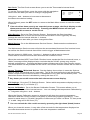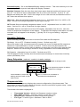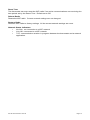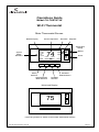
1
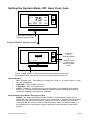
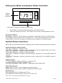
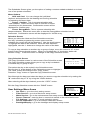
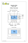
™
Operations Guide
Model CH-THSTAT-W
Wi-Fi Thermostat
Main Thermostat Screen
Backlite Display
Room Temperature
Room RH
Setpoints
Temperature
Setting
4:30 PM
Sys Off
Fan Off
Hold
Link OK
System
Status
Indicators
MENU
74
2
COOL
MODE
AUTO
FAN
RH 40%
72 H
75 C
Warmer
Cooler
HOLD
Menu
Selection
Run/Hold
Mode Selection
Heating/Cooling
Mode Selection
Fan Mode
Selection
Minimized Display
(displayed after screen timeout
75
Press any button to return to the main thermostat screen
Doc ID 2014-05-223 • Rev 02
Page 1
Setting the heating or cooling temperature setpoint
4:30
PM
Sys Off
MENU
75
HEAT
MODE
AUTO
FAN
64H
Press a button to
go to the setpoint
change screen
82C
HOLD
Press the up or down arrow buttons to
set the desired temperature setpoint
Setpoint change screen
HEATING SETPOINT
70
Done
Raise Temperature
Lower Temperature
COOL
Pressing the up
or down buttons
will increment the
setpoint 1 degree.
Press and hold
the button to
ramp the setpoint.
Change Mode button
Press “DONE” button to set the setpoint and exit back
to the main thermostat screen or wait for the screen to
automatically time out.
!
If the System Mode is OFF, pressing either the Up or Down buttons will take you
to the System Mode screen. You must first set an operating mode before you can
set or change the setpoint.
!
To change the Heat Setpoint you must be in the Heating mode, to change the Cool
Setpoint you must be in the Cooling mode. If you are in Auto mode, the mode of the
last system call will be the setpoint screen displayed. Press the Change Mode button
to toggle between Heat and Cool mode.
Setpoint Push: Note that you cannot lower the cooling setpoint below the heating
setpoint. The thermostat will “push” the heating setpoint lower if you try to lower the cooling
setpoint below the heating setpoint. It maintains a 3 degree separation between the
heating and cooling setpoint. The same is true for raising the heating setpoint above the
cooling setpoint. Again the thermostat will “push” the cooling setpoint up to maintain the 3
degree separation.
Doc ID 2014-05-223 • Rev 02
Page 2
Setting the System Mode: Off, Heat, Cool, Auto
4:30 PM
75
Sys Off
MENU
HEAT
MODE
AUTO
FAN
64H
82C
HOLD
Press Mode button to
change system mode
System Mode change screen
SYSTEM MODE
OFF
HEATING
COOLING
AUTO
Done
MODE
Press the
UP or
DOWN buttons
or
MODE button
to select the
desired system
mode.
Press “DONE” button to select the mode and exit back to the main
thermostat screen or wait for the screen to automatically time out.
System Modes
•
OFF: System is off. No heating or cooling will come on. If system was on, it will
turn off immediately.
•
HEATING: Only heating will occur.
•
COOLING: Only cooling will occur.
•
AUTO: Heating or cooling will come on according to the heating and cooling
setpoints. The system will automatically switch between heating and cooling
modes as needed to maintain the setpoints.
Special Heat Pump Mode: Emergency Heat
•
EHEAT: An additional system mode, “EHEAT” for Emergency Heat will be
displayed if the HVAC system type is set to Heat Pump. If there is a compressor
failure with the Heat Pump system, setting the mode to EHEAT will allow the
supplemental Aux heat to come on first whenever there is a call for heating. It
also disables the compressor output to prevent further damage to the HVAC
system.
Doc ID 2014-05-223 • Rev 02
Page 3
Setting Fan Mode and System Status Indicators
4:30 PM
System
Status
Indicators
Cool
Fan On
Hold
Link Ok
MENU
RH 40%
75
HEAT
MODE
AUTO
FAN
64H
82C
HOLD
Press the Fan button to change the Fan mode
•
•
AUTO FAN: Fan automatically operated by the HVAC system.
FAN ON: Manual Fan mode. Fan stays on until mode is changed back to Auto.
Optional Fan Mode
Fan Cycler. If the Fan Cycler feature is enabled in the Installer Setup, the additional fan
mode “Cycle” will be shown in the Fan Mode menu. This mode cycles the fan on and off
continuously for fresh air ventilation according to the settings in the Installer Setup.
System Status Indicators
When the main thermostat screen is displayed, the on-screen labels indicate the following.
System Operation mode indicator
“SYS OFF” displayed > System is OFF
1
“SYS MOT” displayed > System is OFF and Minimum Off Time (MOT) delay On is active
“HEAT ON” displayed > System is ON and heating
“COOL ON” displayed > System is ON and cooling
2
“HEAT MRT” displayed > System is ON and heating. Minimum Run Time (MRT) delay off
is active.
“COOL MRT” displayed > System is ON and cooling. Minimum Run Time (MRT) delay off
is active.
Staging display
nd
“2 Stg” displayed > Stage 2 heating or cooling is ON
“Aux Heat” displayed > Stage 3 heating is ON
For Heat Pump systems only: “EHEAT” > emergency heat mode active
Home/Away display
Home mode is active (current setpoints are being used)
Away setback mode is active (setback setpoints are being used)
System Alerts
Alert Messages:Filter or Maintenance Timer
WiFi Network connection Status: No Link, Link OK, TCP
Notes 1 and 2: See MOT and MRT descriptions on page 5
Doc ID 2014-05-223 • Rev 02
Page 4
Thermostat Operation
Minimum Run Time (MRT)
The thermostat has a Minimum Run Time after the start of any heating or cooling call. This
minimum run time assures even heating and cooling cycles. The MRT delay will keep the
system on even if reaches setpoint or you change the setpoint to a temperature that would
satisfy the call, until the MRT expires. Changing the Mode to OFF will cancel the MRT and
the system will turn off immediately. The MRT can be adjusted in the Installer Settings
menu of the thermostat.
Note: The MRT status is shown in the thermostat System Status on-screen labels.
Minimum Off Time (MOT)
The thermostat has a Minimum Off Time after any heating or cooling call is finished. This
delay prevents rapid heating/cooling cycles and also provides “short cycle protection” for
compressor calls. This delay may be noticeable when you change a setpoint and it does
not respond immediately due to another call that has recently completed and the MOT
delay timer is preventing the system from restarting. The MOT delay time can be adjusted
in the Installer Settings menu of the thermostat. There is a minimum of 5 minutes delay to
assure compressor protection.
Note: The MOT status is shown in the thermostat System Status on-screen labels.
Doc ID 2014-05-223 • Rev 02
Page 5
Menu Selection
4:30 PM
Sys Off
MENU
75
HEAT
MODE
AUTO
FAN
64H
82C
HOLD
Press Menu button to go
to the main menu screen
Menu Selection
User Settings
Humidity Settings
Thermostat Info
WiFi Network Status
Done
Press DONE to go back to
the main thermostat screen
Select
Use the
UP/DOWN
buttons to select
the desired menu
item
Press SELECT to go to the
menu item screen
Main Menu Items
•
•
•
•
•
•
•
Schedules > Optional, used to view and set programmable schedules
User Settings > set various user preferences
Usage Graph > show heating and cooling run times
Away Setpoints > show and set the heating and cooling setback setpoints
Thermostat Info > displays thermostat setup info
WiFi Network Status > displays IP Network Info
WiFi Setup > Set IP Network parameters
Schedules is an optional menu item. It will only show up in the menu list if “Schedules”
is enabled in the Installer settings for the thermostat. Provides for local schedule control.
The Schedules Screen allows you to review and set the setback schedule for the
thermostat. The thermostat has a 4 x 7 schedule. Four times a day can be selected for
changes to the heating and cooling setpoints. Each day of the week can have a different
schedule. Groups of days can be copied with the same schedule. When the thermostat is
set to “Run” mode, the schedule will be executed daily, with the setpoints being changed as
per that days schedule stored in the thermostat. “Hold” mode stops schedule operation
and holds the current setpoints until changed manually or by network commands.
Doc ID 2014-05-223 • Rev 02
Page 6
The Schedules Screen gives you the option of setting a custom setback schedule or to load
one of two preset schedules.
Menu Options
Select Schedule
•
Heat and Cool: You can change the individual
Heat and Cool
day/hour and setpoints for the Heating and Cooling schedule
Preset: Comfort
by selecting this menu item.
Preset: Energy Miser
•
Preset: Comfort: This is a preset schedule with
mild setbacks. Select this menu item to load the Comfort
Done
Select
schedule into the thermostat. Confirmation screen will be
displayed for Yes/No entry.
•
Preset: EnergyMiser: This is a preset schedule with
deeper setbacks. Select this menu item to load the EnergyMiser schedule into the
thermostat. Confirmation screen will be displayed for Yes/No entry.
Schedule Screen
When you select the Heat and Cool Schedule menu item,
the “day” schedule programming screen opens and the
schedule for current day will be displayed. Use the scroll buttons
to highlight the data to be modified. Once the data has been
highlighted, use the +/- buttons to change the value of the data.
Monday Schedule
Wake
Day
Eve
Sleep
Time
Heat
06:00 A 70
08:00 A 62
04:00 P 70
10:00 P 62
+
-
Cool
79
85
78
82 C
DONE
NEXT
To copy a days schedule to another day or group of days, move the cursor to “C” on the
bottom right of the schedule screen. When you highlight the “c”, the button below will
become “Copy”. Press this button to change to the Copy Schedule Screen.
Copy Schedule Screen
The Copy Schedule screen is a sub screen of the Schedule screen.
The Copy Schedule screen allows you to copy a day’s schedule
to another day or group of days.
First select the day to be copied in the Schedule screen.
Scroll to the “c” at the bottom of the Schedule screen to highlight it.
The “Next” button will change to the “Copy” button.
Press the “Copy” button to open the Copy Schedule screen.
Copy Monday Schedule
T0
Yes
Tue Wed Thu Fri Sat Sun
N
N
N N N N
BACK
No
COPY
Scroll through the days and select the days you want to copy the schedule to by setting the
“N” under each day to “Y” by using the Yes/No buttons.
After selecting all the days desired, press the “COPY” button.
Exit the Copy Schedule screen with the “DONE” button.
User Settings Menu Items
•
•
•
•
•
•
•
User Settings
Set Clock
Filter Service
Maint Service
Screen Timeout
0
Set Clock > go to the clock setting screen
Filter Service > go to the filter timer setup screen
Done
Maint Service > go to the maintenance timer setup screen
Screen Timeout > sets the time in seconds to switch to the minimized screen
F/C Settings > go to the F/C mode selection screen
Sensor Calibration > go to the sensor calibration screen
Backlight/Display > go to the backlight and display setup screen
Doc ID 2014-05-223 • Rev 02
Select
Page 7
Set Clock: The Set Clock screen allows you to set the Thermostat’s internal clock.
To set the Time and Date, move the cursor with the navigation
arrows until the data you want to change is highlighted.
Using the + and – buttons to increment or decrement
the data to the desired setting.
Set Clock
Time
Date
Day
08:00 AM
01/01/11
Mon
Back
+
Set
When finished, press the SET button to return to the Main Menu screen or wait for screen
to timeout.
!
If the clock has been reset by an extended power outage, the Clock display on the
thermostat screen will be blinking. Pressing the MENU button will take you
directly to this screen to set the clock.
Filter Service: Go to the Filter Service Screen. Sets/resets the filter timer/alert.
Shows filter runtime in hours and the service interval alert in hours (typically 300 hrs)
Change the service interval with the +/- buttons.
Reset the service alert after you have changed the filter.
Maint Service: Go to the Maintenance Service Screen. Sets/resets the maintenance
timer/alert.
The Maintenance Service screen will show the accumulated Heat and Cool runtime hours
as well as the Service Interval that will be used to trigger a Maintenance alert.
Service interval is 3000 hours. Use the +/- buttons to adjust service interval.
Press reset to clear the service alert and reset the runtimes to zero.
When the combined HEAT and COOL Runtime hours equals the Service Interval hours, a
“Maint” message will be displayed as a reminder that the HVAC system may require
periodic maintenance. Pressing the Menu button will take you to the Filter Service screen.
The Reset button can be pressed and the HEAT and COOL Runtime values will be reset to
zero.
Screen Timeout: Minimized Screen. Set the display timeout time in seconds. Options
are 0 or 15 to 120 (default set to 0 seconds). This is the time before the main thermostat
screen reverts to the minimized screen of temperature only, after the last button press. The
Minimized Screen feature is disabled by setting this time to “0”.
! Any button press will restore the main thermostat screen display.
F/C Settings: Go to the F/C Settings Screen. Select which temperature display mode you
desire, Fahrenheit (F) or Celsius (C).
Sensor Calibration: Go to the Sensor Calibration Screen. This screen allows you to
adjust the calibration of the internal sensor. You can change the temperature calibration by
+/- 7 degrees using the + and – buttons
When the Sensor Calibration screen is selected it will show the current temperature
calibration and the current number of degrees of offset being applied (typically 0). If the
sensor’s actual temp is (74) with 0 degrees of offset and you want it to show 75, then press
“+” to add 1 deg and it will show (75).
!
You can refresh the info on this screen by pressing the right hand (blank) button.
When you close this screen, it may take a few seconds for the temperature displayed on
the main thermostat screen to update to the new temperature selected.
Doc ID 2014-05-223 • Rev 02
Page 8
Backlite/Display: Go to the Backlite/Display settings screen. This menu allows you to set
the backlight timeout period and adjust the display contrast.
Backlite Timeout: Sets the time from last button press that the backlite will timeout and
turn off. The timeout value is adjustable from 0 or 20 to 120 seconds. If set to “0”, the
Backlite will always be ON. If set in the range of 20 to 120 seconds, the Backlite will turn
OFF after the selected time expires.
ON Level: Sets the backlight brightness when it is on. Adjustable from 0 to 100% in 5%
steps. Screen will change brightness as you adjust setting.
OFF Level: Sets the backlight brightness when it is off. Adjustable from 0 to 100% in 5%
steps. Can be 0% = off or a low level for night viewing.
Contrast: Sets the contrast level of the LCD display, adjustable from 0 to 20. Use this
control to adjust the sharpness of the display. To light and the display looks faded, too dark
and dark lines will appear in the display. Typically 10-15 is a good setting. Adjust as
needed.
Humidity Settings
Select Humidity Settings menu item to set the RH mode and RH setpoint.
RH Mode. On or OFF. Enables Humidity Control. Default set to Off.
When RH mode is ON, the thermostat will compare the room RH with the RH setpoint to
determine if dehumidification control is needed. If RH is above the RH setpoint, the
thermostat will continue cooling calls to attempt to lower the room RH to the meet the RH
setpoint. Maximum overcooling is limited to 2 deg (adjustable in the Installer Settings).
RH Setpoint. Adjustable from 20 to 80%. Default set to 55%.
The RH setpoint is the humidity level the thermostat will attempt to meet when humidity
control (RH Mode) is On.
Away Setpoints (optional – enable in installer settings)
Away setpoints are used when the thermostat is set to the setback or away mode.
Away Setpoints
Away – Heat
Away – Cool
Done
Press DONE to store the
setting and exit back to the
main menu
+
65
80
-
Use up/down buttons to select
setpoint to change
Set
Use +/- buttons to increase or
decrease the temperature
Thermostat Info
The Thermostat Info screen displays the current configuration of the thermostat. This
information is useful for quick check of firmware versions and HVAC system setup. It also
shows the WiFi radio firmware version.
Thermostat information displayed is:
•
•
•
•
Thermostat Version - Model and firmware version number.
WiFi Radio Version – Firmware version of the WiFi radio
System Type - Standard or Heat Pump HVAC system
Fan Type – if HVAC type = Standard: Gas or Elect
Doc ID 2014-05-223 • Rev 02
Page 9
•
•
OR
Changeover – if HVAC type = Heat Pump: Changeover with cool or changeover
with heat
Network Address – This is an internal address, not the IP address
Thermostat Info Screen
Thermostat Info
Model Number
WiFi Radio Version:
System Type:
Fan Type:
Network Address:
Done
Status
Ver: 02.07.01
02.36
Standard
Gas
1
Setup
Status Button: Pressing the Status button will display the status of the thermostat relay
outputs. This can be helpful information in trouble shooting installation problems.
Setup Button: This is a quick link to the mechanical setup for the HVAC system type. If
your HVAC is not the default HVAC type (Standard/Gas) or does not match the settings
displayed, press this button to go directly to the Installer Settings/Mechanical settings menu
to set the correct settings.
Doc ID 2014-05-223 • Rev 02
Page 10
WiFi Setup
WiFi Network Status Screen
WiFi Network Status
SSID: A
Chan: 6
Security: Open
DHCP: ON
IP: 192.168.1.100 : 2000
SUB: 255.255.255.0
Auth: Y
GW: 192.168.1.1
Assoc: Y
Done
This screen is selected from the main menu and displays the current WiFi network
parameters:
SSID: Current network the thermostat is connected to
Channel: Current WiFi channel
Security: Security protocol: Adhoc, Open, WEP, WPA1,WPA2,
IP: IP address assigned to the thermostat
Sub: Subnet mask
GW: Gateway IP address
Auth: Authenticated status by network
Assoc: Associated status with network
WiFi Setup Menu
WiFi Setup
WPS Connect
SSID
A
DHCP
Enabled
Security
WPA2
Done
Select
This screen is selected from the main menu to setup up the thermostat’s WiFi connection
parameters. Menu items include:
•
•
•
•
•
•
•
•
•
•
•
•
•
•
•
WPS Connect
SSID
DHCP
Security
Key
IP
SUB
GW
DNS
Port
Chan
Adhoc Mode
Reset Time
Reboot Radio
Restore Radio
WPS Connect
If the network router has WPS (Wi-Fi Protected Setup) capability, the thermostat can
automatically find and join a secure Wi-Fi network.
•
Place the Router / Access Point into WPS mode
•
In the WiFi Setup screen, select WPS Connect and press the “Select” button.
•
A WPS Connection progress window will pop up and indicate WPS status
Doc ID 2014-05-223 • Rev 02
Page 11
Upon successful completion, the WiFi Network Status screen will be displayed
•
SSID
Select SSID and press the “Select” button to scan for available networks.
After the thermostat completes a network scan, the available networks will be displayed.
Use the up/down arrow buttons to scroll through the available networks
WiFi Networks
Network1
Network2
Network3
Network4
Done
New
II
IIII
II
III
Scan
Shows network SSID, signal strength and open / locked network status
Join
Press Join to join the selected network
Press Scan to scan again
Press New to enter a new SSID network name to join
DHCP Configuration
If the network router supplies IP address Dynamically (DHCP):
•
Select “SSID” from list shown on screen, press “Join” button
•
Or, press the Scan button to rescan for SSID
•
Or, manually enter the SSID network name (Case / character capable)
•
Select DHCP enabled (this is the default mode)
•
Once the router / SSID is selected, the WiFi radio will auto-detect the appropriate
security protocol
•
Or, manually select the security type (Adhoc, WPA1, WPA2, WPA1+WPA2,
WEP)
•
Enter the security key (Case sensitive and character capable)
•
Select Done to save settings
Security
Select the security type for the network selected: Adhoc, Open, WEP, WPA1,WPA2
Key
Enter the Passphrase for the network selected.
IP Address (for static IP configurations)
To set a Static IP address:
WiFi Setup
Key
xxxxxxxx
•
Disable DHCP by pressing the “-“ key
IP
0.0.0.0
•
Enter IP Address (if static IP)
SUB
0.0.0.0
GW
0.0.0.0
•
Enter the Subnet Mask
Done
•
Enter the Default Gateway address
•
Enter the DNS address
•
Enter the Port number. The WiFi radio communicates on Port 2000, this
should be left in the default setting
•
Enter the Channel number. Auto mode is the default (recommended)
•
Select Done to save settings
Select
Ad Hoc Mode
The Wi-Fi radio can also be placed into Ad Hoc mode which enables Peer-to-Peer
communication without a network router.
•
Select Ad Hoc in the Setup menu. The default mode is Disabled
•
Press the “+” key to change to Enabled
o
sets the thermostat IP address to: 169.254.1.1
o
sets the Subnet to: 255.255.0.0
•
Select Done to save settings
Doc ID 2014-05-223 • Rev 02
Page 12
Reset Time
The thermostat can auto reset the WiFi radio if no active communications occurs during the
time period set by the Reset Time. Default set to Off.
Reboot Radio
Resets the WiFi radio. Current network settings are not changed.
Restore Radio
Restores WiFi radio to factory settings. All the current network settings are reset.
Network Status Indicators
•
No Link: no connection to a WiFi network
•
Link OK: connected to a WiFi network
•
TCP: communication session in progress between the thermostat and a network
application.
Doc ID 2014-05-223 • Rev 02
Page 13
FCC/IC
INFORMATION TO USER
This device complies with Part 15 of the FCC Rules. Operation is subject to the following
two conditions: (1) This device may not cause harmful interference, and (2) This device
must accept any interference received, including interference that may cause undesired
operation.
This equipment has been tested and found to comply with the limits for Class B Digital
Device, pursuant to Part 15 of the FCC Rules. These limits are designed to provide
reasonable protection against harmful interference in a residential installation. This
equipment generates and can radiate radio frequency energy and, if not installed and used
in accordance with the instructions, may cause harmful interference to radio
communications. However, there is no guarantee that interference will not occur in a
particular installation. If this equipment does cause harmful interference to radio or
television reception, which can be determined by turning the equipment off and on, the user
is encouraged to try to correct the interference by one or more of the following measures.
•
•
•
•
Reorient or relocate the receiving antenna
Increase the separation between the equipment and receiver
Connect the equipment into an outlet on a circuit different from that to which the
receiver is connected
Consult the dealer or an experienced radio/TV technician for help
Any changes or modifications not expressly approved by the party responsible for
compliance could void the user’s authority to operate the equipment.
This device complies with Industry Canada license-exempt RSS standard(s). Operation is
subject to the following two conditions: (1) this device may not cause interference, and (2)
this device must accept any interference, including interference that may cause undesired
operation of the device.
Le présent appareil est conforme aux CNR d'Industrie Canada applicables aux appareils
radio exempts de licence. L'exploitation est autorisée aux deux conditions suivantes : (1)
l'appareil ne doit pas produire de brouillage, et (2) l'utilisateur de l'appareil doit accepter
tout brouillage radioélectrique subi, même si le brouillage est susceptible d'en
compromettre le fonctionnement.
Doc ID 2014-05-223 • Rev 02
Page 14