1
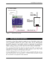
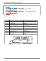
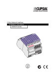
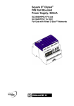
C-Bus DIN Rail Power Supply, 350 mA
Installation Instructions
5500PS Series
US
LISTED
© Copyright Clipsal Integrated Systems Pty Ltd 2005. All rights reserved. This
material is copyright under Australian and international laws. Except as permitted
under the relevant law, no part of this work may be reproduced by any process
without prior written permission of and acknowledgement to Clipsal Integrated
Systems Pty Ltd.
Clipsal is a registered trademark of Clipsal Australia Pty Ltd.
The information in this manual is provided in good faith. Whilst Clipsal Integrated
Systems (CIS) has endeavoured to ensure the relevance and accuracy of the
information, it assumes no responsibility for any loss incurred as a result of its use.
CIS does not warrant that the information is fit for any particular purpose, nor does
it endorse its use in applications which are critical to the health or life of any
human being. CIS reserves the right to update the information at any time without
notice.
V2.0 July 2005
Contents
1.0
Product Range
5
2.0
Description
5
2.1
Why Use a C-Bus Power Supply?
5
3.0
Installation Considerations
6
4.0
Wiring Instructions
6
5.0
C-Bus Network Connection
7
6.0
Status Indicators
9
6.1
C-Bus Indicator
9
6.2
Unit Indicator
9
7.0
Output Current Limiting
10
8.0
Power Surges and Short Circuit Conditions
10
9.0
Megger Testing
11
Programming
11
10.0
11.0
Electrical Specifications
12
12.0
Mechanical Specifications
13
13.0
Standards Complied
14
14.0
Warranty
15
C-Bus DIN Rail Power Supply, 350 mA
4
Installation Instructions
1.0
Product Range
5500PS
C-Bus DIN Rail Power Supply, 350 mA (220 to 240 V)
E5500TPS
C-Bus DIN Rail Power Supply, 350 mA (110 to 120 V)
2.0
Description
The 5500PS Series C-Bus Power Supply provides up to 350 mA to a C-Bus
network, at up to 36 V DC. This is sufficient to power approximately
15 × 22 mA C-Bus units such as Neo and Ulti Saturn switch plates. The unit
is DIN rail mounted, measuring 4 modules wide (1 module = 17.5 mm).
C-Bus connection is achieved through the use of RJ45 connectors,
allowing similar units to be quickly looped together.
2.1
Why Use a C-Bus Power Supply?
The C-Bus Power Supply is designed to have a defined value DC output
resistance, and at the same time present a high AC impedance at C-Bus
communication frequencies (500 to 5000 Hertz). For this reason, standard
off the shelf power supplies are not suitable for use with a C-Bus network.
5
C-Bus DIN Rail Power Supply, 350 mA
3.0
Installation Considerations
A maximum total current of 2 Amps may be supplied to a C-Bus network.
This is due to power dissipation limitations of the cable. It means that up
to five 5500PS Series units may be connected to an individual C-Bus
network if no other C-Bus power supplies are connected. Some C-Bus units
such as the L5508D1A Dimmer and the L5508RVF Voltage Free Relay,
have built-in power supplies. These must be taken into account when
determining the total current available.
To minimise voltage drop due to cable resistance, Power Supplies should
be distributed evenly along a C-Bus network. The minimum operating
voltage of any C-Bus unit on the network is 15 V DC. To achieve the most
efficient installation, it is recommended that the maximum voltage drop
between a C-Bus unit and the closest power supply is limited to 10 volts.
For simplicity, it can be assumed that the Cat-5 C-Bus cable resistance is
1 ohm per 10 metres. The DC output resistance characteristic of the
5500PS Series ensures that the load is shared relatively evenly between
multiple Power Supplies.
4.0
Wiring Instructions
A wiring diagram for the 5500PS Series Power Supply is provided in
Figure 1. Consider the following points when installing the unit:
•
•
•
•
•
6
An individual C-Bus network must not be supplied with more than
2 Amps total current.
Fix mains cabling in the distribution board using cable ties or
trunking as required by local wiring rules. Take care not to allow
copper strands to enter the DIN unit’s apertures.
Apply a maximum torque of 1.4 Nm to the mains rated screw
terminals.
Rubber bungs are supplied for unused RJ45 connectors, to stop
foreign bodies from entering the unit. Always install these bungs
when the unit is mounted inside a mains rated enclosure.
Use copper wire only.
Installation Instructions
AC Mains Supply
Active (Line/Hot)
Neutral
C-Bus
Cat-5 Cable
5005C305B
Earth
N
A/L
Cat-5
Surface Box
SMRJ88A5/1
Unit
C-Bus
2
1
4
5
8
7
6
3
Power Supply
C-Bus CONNECTIONS
C-Bus Network
C-Bus Patch Cord
Figure 1 – 5500PS Series wiring
5.0
C-Bus Network Connection
Connection to the C-Bus network is made via one of the RJ45 sockets. Use
Cat-5 Unshielded Twisted Pair (UTP) C-Bus cable, and an appropriately
wired RJ45 plug. Pinouts and cable conductor assignments are provided in
Figure 2 and Table 1. The RJ45 sockets are internally connected. The
Clipsal catalogue number for the C-Bus Cat-5 UTP cable is 5005C305B.
It is recommended that the Remote Override (On/Off) connections be
maintained for correct operation of these services across the C-Bus
network, even if they are not intended to be used.
A Clipsal RJ5CB300PL Cat-5 UTP patch cord is included with the unit for
easy interconnection. No more than 5 × 5500PS Series products should
be connected to one physical C-Bus network.
7
C-Bus DIN Rail Power Supply, 350 mA
C-Bus Positive:
blue + orange
C-Bus Negative: blue & white + orange & white
Remote OFF:
brown + brown & white
Remote ON:
green + green & white
Figure 2 – C-Bus cable conductor assignments
Pin
C-Bus Connection
Colour
1
Remote ON
green & white
2
Remote ON
green
3
C-Bus Negative (-)
orange & white
4
C-Bus Positive (+)
blue
5
C-Bus Negative (-)
blue & white
6
C-Bus Positive (+)
orange
7
Remote OFF
brown & white
8
Remote OFF
brown
87654321
87654321
Table 1 – RJ45 sockets and C-Bus pinouts
8
Installation Instructions
6.0
Status Indicators
6.1
C-Bus Indicator
The “C-Bus” indicator shows the status of the C-Bus network at the unit. If
sufficient network voltage is present, the indicator illuminates (as a
continuous green light). If a network is connected which has a higher
current load than the power supplies support, the indicator flashes to
show a marginal network voltage.
Indicator Status
Meaning
On
Power is on and functional
Flashing
The network voltage is marginal
(15 V < voltage < 20 V)
Off
Mains power is not connected or C-Bus
voltage is below 15 V
Table 2 – The “C-Bus” indicator
6.2
Unit Indicator
The “Unit” indicator shows the status of the individual unit. When mains
power is supplied, the indicator illuminates (as a continuous green light).
Indicator Status
Meaning
On
Normal operation
Off
No mains power is connected
Table 3 – The “Unit” indicator
9
C-Bus DIN Rail Power Supply, 350 mA
7.0
Output Current Limiting
One of the advantages of the low C-Bus DC operating voltage, is that
connections can be made whilst the network is powered up. Should a
short circuit occur, the Power Supply’s output current limiting / overload
circuitry protects it from damage for an indefinite period of time. The
Power Supply’s defined output resistance and current limiting characteristic is illustrated in Figure 3.
36V
normal operation output resistance
(approx. 25
27V
overload operation
output resistance
(>600
Output
Voltage
0
Output Current
0.34A 0.38A
Figure 3 – Output voltage vs output current
8.0
Power Surges and Short Circuit Conditions
External power surge protection devices should be used to enhance
system immunity to mains voltage surges. It is recommended that
overvoltage equipment such as the Clipsal 970RMT be installed at the
switchboard.
The C-Bus Power Supply output includes protection against short circuits
and electrical overload. The unit electronically isolates mains power from
the C-Bus network.
10
Installation Instructions
9.0
Megger Testing
Megger testing must never be performed on the C-Bus data cabling or
terminals as it could degrade the performance of the network.
Megger testing of a mains electrical installation that has C-Bus units
connected will not damage the units. Since C-Bus units contain electronic
components, this should be taken into account when interpreting megger
readings.
10.0 Programming
Unlike other C-Bus units, the 5500PS Series Power Supply does not
require programming.
11
C-Bus DIN Rail Power Supply, 350 mA
11.0 Electrical Specifications
Parameter
Description
5500PS
E5500TPS
Nominal supply voltage
220 to 240 V AC
110 to 120 V AC
Frequency range
47 to 63 Hz
C-Bus output voltage
36 V DC maximum
C-Bus output current
< 350 mA
Output short circuit
current
< 400 mA
DC output resistance
25 Ω (approx.)
C-Bus AC output
impedance
> 60 k Ω @ 1 kHz
Electrical isolation
3.75 kV RMS from C-Bus to mains
Maximum units per
C-Bus network
5
Power supply type
Electronic transformer with high output
impedance
Quiescent power
15 W maximum
Warm up time
3 seconds
Operating temperature
0 to 45 °C (32 to 113 °F)
Operating humidity
10 to 95% RH
12
Installation Instructions
12.0 Mechanical Specifications
Parameter
Description
Dimensions (W×H×D)
72 × 92 × 63 mm
(2.83 × 3.62 × 2.48 inches)
Weight
190 g (6.7 oz)
Mains terminals
Accommodates 2 × 1.5 mm2 or 1 × 2.5 mm2
(2 × 16 AWG or 1 × 13 AWG)
C-Bus connections
2 × RJ45 sockets (in parallel)
72 mm
N
63 mm
A/L
Unit
92 mm
C-Bus
Power Supply
C-Bus CONNECTIONS
13
C-Bus DIN Rail Power Supply, 350 mA
13.0 Standards Complied
Australian/New Zealand EMC & Electrical Safety Frameworks and Standards
The 5500PS product complies with the following:
Regulation
Electrical Safety
EMC (C-Tick)
Standard
AS/NZS 3100
Title
General Requirements for
Electrical Equipment
AS/NZS 3108
Requirements for Safety Extra
Low Voltage
IEC61204-3
LV Power Supplies (Emissions)
European Directives and Standards
The 5500PS product complies with the following:
European
Council Directive
EMC Directive
89/336/EEC
Standard
Title
EN61000-3-2, EN61000-3-3
EMC LF Standard
EN61204-3
LV Power Supplies
(Emissions & Immunity)
Low Voltage
Directive
73/23/EEC
EN 61558-1,
EN61558-2-17
Safety of Power
Supplies &
Transformers
US and Canadian Product Safety Standards and US FCC Regulations
The E5500TPS product complies with the following:
LISTED
US
3042248
Standard/Regulation
CSA C22.2 No. 107.1
Title
General Use Power Supplies
UL1012
Power Units Other Than Class 2
Tested to FCC Standards
for Home or Office Use
FCC Part 15
ANSI C63.4
Supplemental Information
This device complies with part 15 of the FCC Rules. Operation is subject to the following two
conditions: (1) this device may not cause harmful interference, and (2) this device must
accept any interference received, including interference that may cause undesirable
operation.
Class B Product
NOTE:
This equipment has been tested and found to comply with the limits for a Class B digital
device, pursuant to Part 15 of the FCC Rules. These limits are designed to provide
reasonable protection against harmful interference in a residential installation. This
equipment generates, uses and can radiate radio frequency energy and, if not installed and
14
Installation Instructions
used in accordance with the instructions, may cause harmful interference to radio
communications. However, there is no guarantee that interference will not occur in a
particular installation. If this equipment does cause harmful interference to radio or
television reception, which can be determined by turning the equipment off and on, the user
is encouraged to try to correct the interference by one or more of the following measures:
•
reorient or relocate the receiving antenna
•
increase the separation between the equipment and receiver
•
connect the equipment into an outlet on a circuit different from that to which the
receiver is connected
•
consult the dealer or an experienced radio/TV technician for help.
Warning: Any changes or modifications not expressively approved by Clipsal Integrated
Systems could void the user's authority to operate this equipment.
Other International Directives and Standards
The 5500PS and E5500TPS products comply with the following:
Regulation
EMC
Electrical
Safety
IEC Standard
61000-4-2, 61000-4-3,
61000-4-4, 61000-4-5,
61000-4-6, 61000-4-11
Title
Immunity to ESD, Immunity to RFI,
Immunity to EFT, Immunity to Surge Voltages,
Immunity to Conducted RFI
61204-3
LV Power Supplies
61558-1, 61558-2-17
Safety of Power Supplies & Transformers
14.0 Warranty
The 5500PS Series C-Bus Power Supply carries a two year warranty
against manufacturing defects (refer to the Warranty Statement).
15
Technical Support and Troubleshooting
For further assistance in using this product, consult your nearest
Clipsal Integrated Systems Sales Representative or Technical
Support Officer.
Technical Support Hotline: 1300 722 247 (Australia)
0800 888 219 (New Zealand)
Technical Support Email:
[email protected]
Sales Support Email:
[email protected]
A list of worldwide contacts, additional product information and
technical resources is provided at http://www.clipsal.com/cis/
Product of Clipsal Integrated Systems Pty Ltd
ABN 15 089 444 931
Head Office
12 Park Terrace, Bowden, SA 5007, Australia
Telephone: (+61) 8 8440 0500
Facsimile: (+61) 8 8346 0845
Email: [email protected]
Web: http://www.clipsal.com/cis/
10358563