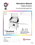
1
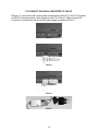
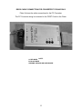
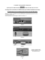
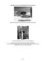
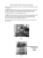
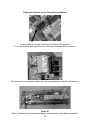
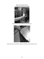
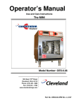
PC-Control / HACCP Network Installation
For Convotherm by Cleveland Combination Oven Steamers
This kit connects a PC to as many as 31 Combis at a maximum distance of 3280 Feet (1000 meters). The
software can download cooking programs, record HACCP information, and monitor the networked
Combis in real-time. This installation manual includes instructions for both RS232 and USB connections
for a PC. Choose the connection that works best for your application and follow the instructions that
apply. If any parts are missing from any kits, please contact Cleveland Range Service at 216-481-4900.
CAUTION
Turn off all power to Combis before installation of PC-HACCP Network.
Follow all Safety and Operating Instructions
Failure to do so can result in injury, and equipment and property damage.
RS232 Correct connection of a PC to Combis using the Communication Module with RS232 Port.
FOR RS232 connection use part number: CPC-HACCP-MU232
Correct connection of a PC to Combis using the Communication Module with USB Port.
FOR USB connection use part number: CPC-HACCP-MUUSB
1333 East 179th Street
Cleveland, Ohio 44110
Phone: (216) 481-4900
Fax: (216) 481 3782
www.clevelandrange.com
260AZH REV. B 3/06
CAUTION
Read and understand this manual before using this PC-HACCP Kit.
Follow all Safety and Operating Instructions
Failure to do so can result in injury, and equipment and property damage.
NOTICE: In addition to the kit, the following wire is required for installation between each oven:
• For standard voltage units: 18/ 2 CPM/CL3P audio wire – e.g.: McMaster-Carr P/N- 71055K76.
• For 480 volt units use 18/2 UL AWM 2501 communication wire – e.g.: Allied Electronics
P/N – 708-1301. (Can be used with all voltage ovens.)
PC–HACCP KIT CONTENTS
6
5
1
4
Photo 1
2
3
1 Software-CD - 300550
2 Network Connection Cable – 300551 (included only w/ 232 kit)
3 Dongle - C5009210
4 PC Interface Converter - C5009156 (included only w/ 232 kit)
5 9 Volt Power Supply for Converter – 300548 (included only w/ 232 kit)
6 Operating Instructions – 260AZV
USB TO RS 232/485 ADAPTER 300555 included only with kit number CPC-HACCP-MUUSB
USB Adapter
USB Cable
Software-CD
See Page 20 for
Installation Instructions
Photo 2
2
RS485 Communication Module p/n C-RS485
1
5, 6, 7
4,7
2
5, 6, 7
PHOTO 3
3
1 Electronic Board (1) – C5019104
2 Connector (1) – C5002091
3 Bracket with Studs (1) – C2114799
4 Control Panel Spacers (2) – C8009030
5 Screws – M3 (2) - 111633
6 Lock Washers (2) – C8016001
7 Hexagon Nuts – M3 (4) – C8004012
3
TO CONNECT THE RS232 CONVERTER TO THE PC
Photos 4, 5, and 6 show the correct cable connections from the PC to the PC Converter
for RS232. Note the position of the Dongle on the PC in Photo 5. Make sure the PC
Converter is connected to the 9-volt DC power supply as shown in Photo 7.
Photo 4
Photo 5
Photo 6
Photo 7
4
RS232 CABLE CONNECTION FOR CONVERTER TO RS485 ONLY
Photo 8 shows the cable connections for the PC Converter.
The PC Converter wiring is connected to the FIRST Combi in the Chain.
Photo 8
NOTE:
A: RED WIRE
B: BLACK WIRE
GROUND: GROUND OR SHIELD WIRE
5
TO CONNECT USB CONVERTER TO RS485 ONLY
IMPORTANT:
ALWAYS USE THE SAME USB PORT WHEN REATTACHING THE USB CABLE TO THE PC!
See Page 20 for instructions for USB hardware and software installation and setup.
The USB software must be installed on the PC before using the USB adapter.
Photos 9, 10, and 11 shows the correct USB cable connections from the PC to the
Converter in Photo 12.
Note the position of the Dongle on the PC in Photo 11.
Photo 9
Photo 10
Photo 11
PHOTO 12 SHOWS WIRE
CONNECTIONS PIN 1, PIN 2,
AND GROUND (PIN 6).
Photo 12
6
Remove the Control Side Cover
Photo 13
Photo 14
Turn the 1/4 turn quick-locks to loosen.
Photo 16
Photo 15
From the bottom edge of the side panel, push up and pull out.
Remove the side panel and set it aside.
7
Remove the Control Panel
Photo 17
Press down and turn counterclockwise to remove the Operation Panel retention screw.
Photo 18
Remove the Operation Panel out from the rear. Be careful not to drop it.
Disconnect the computer cable from the Operation Panel and set the panel aside.
Photo 19
Remove the Control Panel and place it on a work surface as shown.
8
Attaching the Base Plate to the Communication Module
1. Mount the board to the panel using the spacers, nuts and washers included in the kit.
Photo 20
Photo 21
Press the Communication Module Interface onto the Control Module.
Tighten the screws holding the Communication Module to the Control Module.
9
Attaching the Base Plate to the Communication Module
Mount the board to the panel using the spacers and nuts included in the kit.
Photo 22
Photo 23
Photo 24
Complete Assembly of Communication Module Interface and Control Module.
10
Inserting the Communication Module Cable into the Oven
Photo 30
Remove the sanitary seal plug from the underside of the Combi.
Photo 31
Insert the new bushing, P/N 111751 into the opening.
Pull the Communication Module cable through the Bushing.
Pull enough wire through the bottom of the oven to allow ample movement while
attaching the wires to the network boards.
11
Connect the Network Cable to the Communication Module
Take care to match the wire ends or colors to the connections throughout the network to
avoid miswiring.
For RS232 Converter: Attach the wire to the Converter at connection “A” and attach the
other end to connection “A” on the Communication Module. Attach the wire to the
Converter at connection “B” and attach the other end to connection “B” on the
Communication Module. Connect drain/shield as ground
For USB: Attach the network wire to connection 2 on the Converter and attach the other
end to connection “A” on the Communication Module. Attach the network wire to
connection 1 on the Converter and attach the other end to connection “B” on the
Communication Module. Connect drain/shield as ground
The network module in the first oven and all others in the network but the last all has
identical wiring
A
B
Ground
Photo 25
Connection in the
FIRST and all but the
last Combis in the
Network.
“A” to “A”
“B” to “B”
Photo 26
12
Setting the Jumpers on the Communication Module
Photo 27
Jumper setting for the first Combi and all Combis in the Network.
To set the jumpers: gently pull them from the board and install them as shown.
Photo 28
Wire Connection and jumpers positions for last communication module in the Network.
Photo 29
Wires Connected to Communication Module Interface and Control Module Assembly.
13
Photo 33
Secure cable to the upper right spacer as shown in Photo 36.
Photo 35
Place Control Board and Module back into the Combi.
Use wire ties to secure cable away from high voltage, sharp corners and edges, and
moving parts.
Make sure the Control Board can still be removed from the Combi once the Network
Board and cables are attached.
14
Replace the Operation Panel
Photo 36
Remount the Operation Panel back into the Combi.
Photo 37
Press down and turn clockwise to tighten the Operation Panel retention screw.
15
Replace the Control Side Panel
Photo 38
Photo 39
Push up and in from the bottom edge of the side panel.
Photo 40
Photo 41
Turn the 1/4 turn quick-locks to tighten.
See the PC-HACCP Instructions to use the PC-HACCP Network.
16
Directions for Installing the USB Adapter
1. Plug the USB connector into the adapter and connect to one of the USB ports on
the back of your computer.
2. Install the USB drivers onto your computer using the CD provided in the kit.
3. Follow the instructions that are on the CD to configure the COM ports so the
computer can recognize the USB adapter.(See configuration pages for data
speeds and other settings)
4. Configure the USB for COM 2-4 only. The PC-HACCP will only recognize those
COM ports.
5. Record which COM port the USB is connected to and always plug the adapter
into that port when using the PC-HACCP controls.
Select “No not at this time.”
17
Select install from a list of specific location (advanced)
Ignore this screen if it appears:
18
Uncheck “Include this location in the search.”
Click Next. Let search
19
The Hardware wizard will appear a second time:
20
Follow the directions in each screen.
21
Allow search for CD
22
Click Finish to close the screen.
Configure your serial device:
1. Right click My Computer, select properties:
Then select the “Hardware tab” and click on the “Device Manager” button.
23
Expand the Ports (COM & LPT) device
24
Right click on the “USB Serial Port (COM??)” item.
The ?? will be a number greater than 0 and less than 255.
Select the Port Settings tab.
25
Note the COM setting. Only COM1, COM2, COM3, and COM4 can be used by the
HACCP software. To change the COM number, click the Advanced button.
26
If needed click the COM Port Number: drop menu and select and acceptable port
number. If all are marked as (in use) then change one of the other serial devices to a
COM port number higher than 4. Click OK.
27
6. Once the computer recognizes the USB adapter, the dip switches in the adapter
have to be set up for RS485 or RS232 data transfer; chose the correct setting to
match the configuration you are using.
For USB to RS232
Switches 2, 3, 4 are ON
For USB to RS485
Switches 1 and 4 are ON
28
SHOWS WIRE CONNECTIONS PIN 1, PIN 2, AND GROUND (PIN 6).
7. For the adapter to output data for RS485, a jumper inside the metal case must be
positioned correctly. This photo shows the position of the #1 jumper. All other
jumpers should be in the original position.
Place
connect
jumper #1
Jumper #1 Position
8. Place the metal cover back on the adapter and secure the screws.
9. The adapter is now ready for use with the PC-HACCP.
29
This Page for Internal Record Only, Not for Printing
Cleveland Range, LLC
1333 East 179th St, Cleveland, Ohio 44110
Drawing No. 260AZH
Revision Index Page
REVISION HISTORY
REV
A
B
260AZH Production Release Per EO # C-6947
Added new part number for HACCP instruction PER EO # C-7022
116 March 2006
Rev Page
DATE
BY
12-12-05
04-16-06
ERB
ERB
260AZH REV. B