1
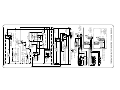
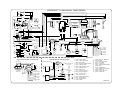
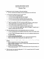
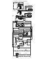
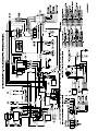
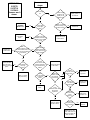
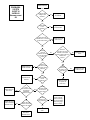
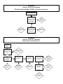
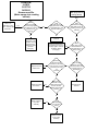
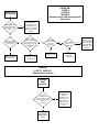
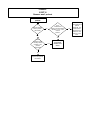
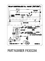
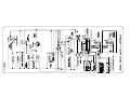
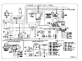
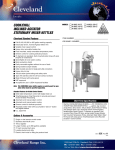
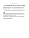
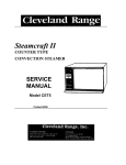
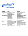
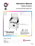
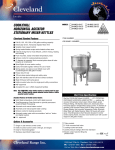
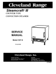
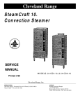
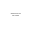
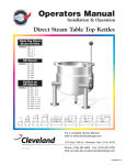
Statement of Responsibilities
This document is for use by experienced and trained Qualified Cleveland Range, LLC Authorized Service
Representatives who are familiar with both the safety procedures, and equipment they service.
Cleveland Range, LLC assumes no liability for any death, injury, equipment damage, or property damage
resulting from use of, improper use of, or failure to use the information contained in this document.
Cleveland Range, LLC has made every effort to provide accurate information in this document, but
cannot guarantee that this document does not contain unintentional errors and omissions.
The information in this document may be subject to technical and technological changes, revisions, or
updates.
Cleveland Range, LLC assumes no liability or responsibility regarding errata, changes, revisions, or
updates.
Qualified Cleveland Range, LLC Authorized Service Representatives are obligated to follow industry
standard safety procedures, including, but not limited to, OSHA regulations, and disconnect / lock out /
tag out procedures for all utilities including steam, and disconnect / lock out / tag out procedures for gas,
electric, and steam powered equipment and / or appliances
All utilities (gas, electric, water and steam) should be turned OFF to the equipment and locked out of
operation according to OSHA approved practices during any servicing of Cleveland Range equipment
Qualified Cleveland Range, LLC Authorized Service Representatives are obligated to maintain up-to-date
knowledge, skills, materials and equipment.
Cleveland Range, LLC
Ph: 1-216-481-4900
Fx: 1-216-481-3782
1333 East 179th St., Cleveland, Ohio, U.S.A. 44110
Visit our Web Site at www.clevelandrange.com
CLEVELAND RANGE 21CET8
SEQUENCE OF OPERATIONS
Mechanical Timer
1. Supply power is sent to the primary of the main transformer.
• 115 VAC is sent from the secondary of the main transformer to the on/off rocker,
2. To turn the unit on, depress the red on/off rocker switch.
• 115 VAC is sent to the red power light.
• 115 VAC is sent to normally open drain valve closing it.
•
115 VAC is sent to H and N on the water level board
3. With the water level board energized and no water in the generator
• 5 seconds later 115 VAC is sent from the FILL terminal to the fill solenoid.
• The fill solenoid opens and the generator fills through the drain valve.
• The water fills to the low probe shorting it to ground
• 115 VAC is sent to the heat standby timer which will energize 3 seconds every 4
minutes to maintain heat while unit is idle
• 115 VAC is sent from the HEAT terminal to the timed manual switch.
4. When the timed/manual switch is in the timed position and time is on the timer
• 115 VAC is sent from the timer to the R2 relay coil
• R2 relay energizes closing the R2A and R2B contacts
• 115VAC is sent through the now closed R2B contacts to the timer motor
• 115 VAC is sent through the now closed R2A contacts through the door switch to the
normally closed contacts of the high limit switch.
• 115 VAC is then sent through the high limit to the coil of condensate solenoid
• The condensate solenoid opens spraying cold water down the compartment drain.
• 115 VAC is also sent through the high limit to the coil of the contactor.
• 115 VAC is sent to the clean light timer.
• When the clean light timer times down 115 VAC is sent to the clean light switch.
• When the clean light switch is depressed the clean light timer is reset.
5. When the contactor coil is energized supply voltage is sent to both of the elements.
• The elements are energized and the water is heated to steam.
• Steam is directed to the cooking compartment.
6. When the timer times out
• 115 VAC is sent to the 3 second timer and then to the buzzer for 3 seconds.
• 115 VAC is removed from the R2 relay.
• R2A contacts open de energizing the heat circuit
• R22B relay contacts open removing the 115 VAC from the timer motor
7. When the water level reaches the high probe then 115 VAC is removed from the FILL
terminal and the fill solenoid is turned off.
8. After the water level drops below the high probe for 5 seconds 115 VAC is sent to the FILL
terminal again.
9. The red on/off switch is depressed and the unit is turned off.
• 115 VAC is removed from the heat and timer circuit.
• 115 VAC is removed from the normally open drain valve allowing the steamer to drain.
• 115 VAC is sent to the 3-minute timer and the fill solenoid is energized for 3 minutes
flushing the drain.
L1
1Ø
TB
6
5
TB
2
CONTACTOR
A
DRYING ELEMENT
HEATING ELEMENTS
DRYING ELEMENT
H1 PRIMARY
WHT
HEATING ELEMENTS
H4
X2 SECONDARY
DESCALE INDICATOR
& RESET SWITCH
TO
PROBES
BUZZER
3 SEC TIMER
2
CONTACTOR
CONDENSER
VALVE
COOLING FAN
DRAIN VALVE
L106347 M
( STACKED UNITS OPTION )
HI LIMIT
SWITCH
R1
( OPT )
1
3
HEAT WATER
BOARD
FILL
H
N
XL HI C
FILL VALVE
NO
X1
L
CONTACTOR
FU
FU
L
NO
POWER ON
R
TIMED
R2
DOOR
SWITCH
(SCS OPT)
R1
C
120V
TO 1Ø IS NOT PERMITTED
FIELD CONVERSION FROM 3Ø
STEAMCRAFT 3.1 MECHANICAL TIMER (PROBE)
CUSTOMER
CONNECTION
380/415V
N
L2
L3
3Ø
L2
L1
3Ø
W/ NEUTRAL
CUSTOMER
CONNECTION
L2
1Ø
CUSTOMER
CONNECTION
L1
3Ø
TB
1
3
1
2
NO
NO
C
MANUAL
3 MIN TIMER
R2A
NO
R2B
TIMED
78
3 2
4
RESET CIRCUIT
BREAKER
L3
BLK
DESCALE
TIMER
POWER
SWITCH
MANUAL
C
C NO
MOTOR
NC
FU
HEAT STANDBY
TIMER
3
1
ELECTRO-MECHANICAL
TIMER
NC
2
FU
FU
INTERMITTENT
BLOWDOWN
TIMER
BLOWDOWN OPTION
R1
C
1
3
FU
STEAMCRAFT 3.1 MECHANICAL TIMER (PROBE)
NO
23
14
16
R2
PNK
ORN/BLK
LT BLU
WHT/BLK
BLK
NC
BLK
BLK
BLK
BLK
17
18
BLK
RED
GRN
WHT
15
C
RED
LT BLU
ORN
C
BLU
19
WHT/BLU
LT BLU
WHT
HI
BLK
XL
X1
X2
208/240
VOLT
JUMPER POSITION
FOR 480 V
OPERATION
H4 H2 H3 H1
H4 H2 H3 H1
HEAT FILL H
BLK
BLK
WHT
WHT
WHT
24
TAN
26
YEL
YEL
L1
7
25
CUSTOMER CONNECTION
WHT/BLK
N
12
WHT/BLK
WHT/BRN
BLU
WHT/RED
BRN
BRN
WHT/BRN
BLK
RED
8
3 2
4
4
TAN
6
78
3
2
1
1
6
5
WHT
COND
FILL
10
BLK
WHT
5
BRN
RED
GRN
RED
BLK
BLK
WHT
YEL
BLU
BLU
RED
WHT/BLU
WHT/GRA
BLK
GRA
3
2
1
L3
L2
TAN
TAN
3
13
BLK
N
WHT
YEL
RED
BLK
2
WHT/BLK
27 28
BLK
REMOVED W / OPT
DOOR SWITCH ( SCS )
WHT
1
FU
BLK
WHT
BLK
WHT
BLK
WHT/BLU
20
FU
BLK
3
2
1
11
9
BLK
BRN
TAN
HEATER
ELEMENT
DRYING ELEMENT
BLK
WHT
HEATER
ELEMENT
RED
WHT
DRYING ELEMENT
RED
PARTS LIST:
INTERMITTENT BLOWDOWN OPTION
SINGLE PHASE WIRING CONFIGURATION
TO
FUSE BLOCK
TIMED/MANUAL SWITCH
7
BRN
L2
L3
BLK
6
TERMINAL BLOCK
CUSTOMER
CONNECTION
( TO HIGH LIMIT )
3
WHT
2
YEL
1
WHT/BLK
WHT/BRN
DRYING ELEMENT
BLK
HEATER
RED
ELEMENT
WHT
DRYING ELEMENT
BLK
HEATER
RED
ELEMENT
WHT
BLK
BLK
( TO COND SOL )
22
3
2
1
WHT
RED
RED
WHT
RED
RED
8
19993 - POWER SWITCH
2
104224 - TIMED / MANUAL SW
3
4
19994 - DESCALE IND RESET SWITCH
20478 - 3 MIN TIMER
5
106911 - DESCALE TIMER
6
109239 - HEAT STANDBY TIMER
7
44168 - TERMINAL BLOCK
8
9
22221 - DRAIN VALVE
107211 - COOLING FAN ( OPT )
10
11
RED
23
GRN
L1
TIMED/MANUAL SWITCH
( THRU SCS )
BLK
N
21 BRN
1
22218 - WATER SOLENOIDS
17
18
19
20
21
22
23
24
25
26
27
28
108880 - DOOR SW ( MAGNETIC )
41350 - BUZZER
110198 - MOTORIZED TIMER
20477 - 3 SEC TIMER
104234 - CONTACTOR
106541 - INTMT BLOWDOWN TIMER
105966 - RELAY
101540 - END SEGMENT
101541 - TERM BLOCK SECTIONAL
20304 - GROUND LUG
109380- 3.5 AMP, 600V FUSE
109374 - FUSE BLOCK
103731 - HI LIMIT SWITCH
12
300022 - CONTACTOR
13
14
15
16
108331 - RESET CIRCUIT BRKR
20535 - TRANSFORMER
107241 - WATER BOARD
107239 - PROBE
P106347 M
STEAMCRAFT 3.1 ELECTRONIC TIMER (PROBE)
CUSTOMER
CONNECTION
380/415V
L1
FIELD CONVERSION FROM 3•
3Ø
L2
TO 1• IS NOT PERMITTED
W/ NEUTRAL
L3
DRYING ELEMENT
N
FU
FU
TB
HEATING ELEMENTS
CONTACTOR
L1
CUSTOMER
CONNECTION
1•
L2
FU
FU
DRYING ELEMENT
TB
CONTACTOR
L1
CUSTOMER
CONNECTION
L2
3•
L3
HEATING ELEMENTS
TB
FU
FU
H4
RESET CIRCUIT
BREAKER
H1 PRIMARY
X2 SECONDARY
X1
120V
BLK
DESCALE
TIMER
L
3 2
4
1
78
A
NO
6
5
WHT
L
NO
DESCALE INDICATOR
& RESET SWITCH
3
2
FILL VALVE
1
POWER SWITCH
POWER ON
3 MIN TIMER
R
HEAT
FILL
H
N
TRANSFORMER
24 VAC
COMPARTMENT
THERMAL SWITCH
WATER
BOARD
TO
PROBES
XL HI C
ELECTRONIC
TIMER
FU
COIL R1
( OPT )
DOOR
SWITCH
( SCS OPT )
MAGNETIC
TIMED
CONTACTOR
R1
NO
MANUAL
C
HI LIMIT
SWITCH
CONDENSER
VALVE
1
2
HEAT STANDBY
TIMER
3
( STACKED UNITS OPTION )
COOLING FAN
BLOWDOWN OPTION
R1
C
NC
1
INTERMITTENT
BLOWDOWN
TIMER
DRAIN VALVE
2
3
L106346 M
Steamer won't
steam
PROBLEM:
21CET8
21CET16
21CEA10
Steamer won't
steam.
Is the red light
on?
Is there supply
voltage to the
primary of the
transformer?
No
No
Supply power to
the steamer.
No
Replace the
transformer.
Yes
Yes
See
STEAMER
WON'T FILL
No
Is there 115 VAC at
the secondary of
the transformer?
Is there water
in the sight
glass?
Yes
Yes
Replace the wires
to the water
board.
No
Is there 120 VAC
between terminals H
and N on the water
board?
Replace the on/off
rocker switch
Yes
Replace the
water board
With a
jumper between XL and
C on the water board, is
there 120 VAC between
N and Heat?
No
No
Is there 120 VAC
between terminals
N and Heat on the
water board?
Yes
Yes
Replace the wire
from the water
board to the long
probe.
No
Is
there debris on
the Long
probe?
Yes
Clean or replace
the probe assy.
Is there
115 VAC to the
common terminal of
the timed/manual
switch?
No
Replace the wires
to the switch.
Is there
115 VAC to the
high limit?
Yes
Does
the unit steam
in Manual
mode?
No
Does the
steamer have
the optional
door switch?
No
No
Replace the
wires to the
high limit.
Yes
No
Yes
Replace the
timer.
Yes
Does
steamer steam with
door switch
bypassed?
Is there 115
VAC leaving
the high limit?
No
Replace the
high limit.
Yes
Is there 115
VAC to the coil
of the
contactor?
No
Replace the
wires to the
contactor coil.
Yes
Yes
Adjust or replace
the door switch.
Is there an
amp draw at
the element?
Yes
Wait longer for the
steam. Heat from the
element will heat the
water to steam.
No
Replace the
element.
Steamer wont fill.
PROBLEM:
21CET8
21CET16
24CEA10
Steamer wont
fill
Yes
Is there supply
voltage to the
steamer?
No
Supply power to
the steamer.
Yes
Is there water
to the
steamer?
No
Supply cold water
to the steamer.
Yes
Is there 120 VAC
between the H and N
on the water board?
No
Replace the on/off
rocker switch.
Yes
Is there
120 VAC
between Fill and
N on the water
board?
No
Remove
the wire from the HI
terminal on the water
board. Is there 120 VAC
between Fill
and N?
No
Replace the water
board
Yes
Yes
Replace wiring to
the fill solenoid.
No
Is there
120 VAC across
the coil of the fill
solenoid?
Is there
debris on the
HI probe in the
probe assy?
Yes
Replace the fill
solenoid
No
Yes
Is
water leaving
the fill
solenoid?
Clean the probes
or replace the
probe assy.
Yes
Replace wiring to
drain valve.
No
Does
the steamer have
the optional
intermittent
blowdown timer?
No
Is there
120 VAC across
the coil of the
drain valve?
Yes
Yes
Replace the wiring
to the intermittent
blowdown timer.
No
Is
there 120 VAC
between terminals
2&3 on the timer?
Yes
Replace the
intermittent
blowdown timer.
Is water
draining from
the generator?
Yes
Replace the drain
valve.
No
If water is leaving
the fill solenoid
and not draining
from the generator
where is it going?
check for leaks..
No
Replace the wire
to the Hi probe.
PROBLEM:
21CET8, 21CET16, 24CEA10
Electronic timer displays "PAUS" and won't count down
Timer displays "paus"
and won't count down
Is steam heating
the cooking
cabinet above 192
degrees (the set
temp of the
thermo-switch)?
No
See
Steamer
won't steam
No
Replace the
electronic timer
Yes
Replace the
thermo-switch
Yes
Does the timer
count down when
the thermo-switch
is bypassed?
PROBLEM:
21CET8, 21CET16, 24CEA10
Steam leaks around the door.
Steam leaks
around the
door
Is COLD water
supplied to both
water lines to the
steamer?
No
Supply cold
water(35-60 psi) to
the steamer.
Yes
Is the door gasket
physically
damaged?
Yes
Turn over the
gasket or
replace it.
No
Is the door out of
alignment?
No
Is the drain
obstructed?
No
Is there 120 VAC
across the coil of
the condensate
solenoid?
Yes
Yes
Yes
Replace the
door bearings
and pins.
Remove the
obstruction
Is the solenoid
opening?
Yes
Replace the
condensate spray
nozzle
No
No
Replace the
wiring to the
condensate
solenoid.
Replace the
condensate
solenoid.
PROBLEM:
21CET8
21CET16
24CEA10
Steamer overfills.
(Water sprays into cooking
cabinet)
There is an
obstruction in the
drain. Remove the
obstruction.
Yes
Does
the rise in the water
level in the sight glass
stop when the cooking
cabinet door is
opened?
Steamer overfills
(Water sprays into the
cooking cabinet)
Start
Does
the water rise in the
sight glass when steam
is generated and 0 VAC
to the fill solenoid?
Yes
Yes
Does
the water level in the
sight glass stop at the
HI (short) probe on the
initial fill?
No
No
No
Replace the fill
solenoid
There is an
obstruction in the
generator causing
it to pressurize.
Delime the steam
generator
thoroughly.
There is an obstruction in
the plumbing to and from
the sight glass. Remove
the debris (delime
thoroughly).
Yes
Does
water spray in the
cabinet before the
water reaches the HI
(short) probe?
No
Replace the three
minute timer.
Remove the
wire from the Fill
terminal on the water
board. Is there 120 VAC
across the coil of the
fill
solenoid?
Yes
Yes
Is
there 120 VAC
across the coil of ;the
fill solenoid when the
HI (short) probe is
submerged?
No
No
Replace the water
level board.
Yes
With HI and C
terminals on the
water board jumped,
Is there 120 VAC
between terminals N
and Fill?
No
Clean or replace
the probe
assembly.
Yes
Is
there debris on
the HI (short)
probe?
No
Replace the wire
to the probe
assembly
Replace the fill
solenoid
PROBLEM:
21CET8
21CET16
24CEA10
Steamer won't stop steaming with
door open
Steamer won't
stop steaming
Is the
timed/manual switch
in the timed position
with no time on the
timer?
No
Steamer will steam
constantly in the
manual position. Put
the timed/manual
switch in the timed
position with no time on
the timer.
Yes
Does the steamer
have the optional
door switch?
No
Does steamer
continue to steam with
both wires removed
from terminal 1 on the
heat standby
timer?
Yes
Is there
120 VAC to the
coil of the
contacter?
Yes
No
Is
there an amp
draw at the
element?
Yes
Yes
No
Replace the timer.
Adjust or replace
the door switch .
Replace the
contactor
Replace the heat
standby timer.
Problem:
21CET8, 24CEA10
Steamer won't preheat
Steamer
won't
preheat
Is the
timed/manual
switch in the timed postion
with time on it or in the
manual
postion?
Yes
See Problem:
steamer won't
steam.
No
This steamer is
not equiped with a
preheat
thermostat. The
timed manual
switch must be in
manual or time
must be on the
timer.
No
When supply
voltage is removed
from the element
steam is still made
for approximately
10 seconds. This
is normal.
Problem:
21CET16
Steamer won't preheat
Steamer won't
preheat
Does the steamer
have a preheat
thermostat
Is the
timed/manual
switch in the timed postion
with time on it or in the
manual
postion?
No
Yes
Yes
Is there
continuity on the
normally closed
contacts of the
preheat
thermostat?
No
Replace the preheat
thermostat
Yes
See Problem:
steamer won't
steam.
No
This steamer is
not equiped with a
preheat
thermostat. The
timed manual
switch must be in
manual or time
must be on the
timer.
Cleveland Range, LLC
Ph: 1-216-481-4900
Fx: 1-216-481-3782
1333 East 179th St., Cleveland, Ohio, U.S.A. 44110
Visit our Web Site at www.clevelandrange.com
L1
1Ø
TB
6
5
TB
2
C
C
NO
FU
FU
L
NO
R
INTERMITTENT
BLOWDOWN
TIMER
TO 1Ø IS NOT PERMITTED
FIELD CONVERSION FROM 3
DRYING ELEMENT
HEATING ELEMENTS
DRYING ELEMENT
H1 PRIMARY
WHT
HEATING ELEMENTS
H4
120V
C
FILL VALVE
DESCALE INDICATOR
& RESET SWITCH
X2 SECONDARY
L
NO
NO
R1
BUZZER
3 SEC TIMER
2
CONTACTOR
CONDENSER
VALVE
COOLING FAN
DRAIN VALVE
L300163 D
( STACKED UNITS OPTION )
HI LIMIT
SWITCH
COIL R2
( OPT )
1
3
WATER LEVEL
R1
X1
LOW WATER
CUT-OFF
DOOR
SWITCH
(SCS OPT)
R3
TIMED
POWER ON
A
CONTACTOR
CONTACTOR
STEAMCRAFT 3.1 MECHANICAL TIMER ( FLOAT )
CUSTOMER
CONNECTION
380/415V
N
L2
L3
L1
L2
3Ø
1
3
1
FU
MANUAL
3 MIN TIMER
FU
FU
3Ø
W/ NEUTRAL
CUSTOMER
CONNECTION
L2
1Ø
CUSTOMER
CONNECTION
L1
3Ø
TB
78
3 2
4
RESET CIRCUIT
BREAKER
L3
BLK
DESCALE
TIMER
POWER
SWITCH
TIMED
R3A
NO
R3B
C
C NO
MOTOR
NC
2
NO
ELECTRO-MECHANICAL
TIMER
R2
1
3
HEAT STANDBY
TIMER
2
NC
BLOWDOWN OPTION
R2
C
1
3
FU
STEAMCRAFT 3.1 MECHANICAL TIMER ( FLOAT )
BLK
3
2
1
20
WHT
WHT
BLK
WHT
BLK
17
BLK
BLK
WHT
BLK
BLK
BLK
LT BLU
19
REMOVED W / OPT
DOOR SWITCH ( SCS )
X2
FU
H4 H2 H3 H1
BLK
BLK
BLK
WHT
WHT
WHT
26
BLU
BLK
R1
2
JUMPER POSITION
FOR 480 V
OPERATION
H4 H2 H3 H1
WHT/GRA
BLU
WHT
BLU
24
YEL
YEL
27 28
BLK
23
WHT
1
FU
X1
208/240
VOLT
WHT/BLU
BLK
BLK
RED
BLK
ORN/BLK
WHT/BLK
PNK
BLK
RED
LT BLU
R3
14
15
WHT/BLU
23
NC
BLU
18
NO
RED
LT BLU
ORN
C
7
L1
L2
L3
25
TAN
RED
WHT/BLK
N
BLU
6
3 2
4
4
78
TAN
3
2
1
1
6
5
BRN
BLK
BLK
RED
10
8
WHT/RED
BLU
BLU
WHT/BLU
5
RED
9
RINSE
COND
FILL
BLK
BLU
WHT
BLK
BLU
YEL
WHT/GRA
BLK
3
2
1
BRN
GRN
WHT
WHT
BLU
WHT/GRA
WHT/GRA
3
12
WHT/BLK
WHT/BRN
GRA
BRN
WHT/BRN
WHT/BLK
CUSTOMER CONNECTION
DRYING ELEMENT
BLK
WHT
HEATER
ELEMENT
RED
11
BLK
BLK
TAN
HEATER
ELEMENT
WHT
DRYING ELEMENT
BRN
RED
PARTS LIST:
INTERMITTENT BLOWDOWN OPTION
SINGLE PHASE WIRING CONFIGURATION
TO
FUSE BLOCK
7
N
BRN
BRN
L2
L3
BLK
6
TERMINAL BLOCK
CUSTOMER
CONNECTION
WHT/BLK
WHT/BRN
DRYING ELEMENT
BLK
HEATER
RED
ELEMENT
WHT
DRYING ELEMENT
BLK
HEATER
RED
ELEMENT
WHT
( TO HIGH LIMIT )
3
WHT
2
YEL
1
BLK
BLK
( TO COND SOL )
23
22
3
2
1
WHT
RED
RED
R2
WHT
RED
RED
8
19993 - POWER SWITCH
104224 - TIMED / MANUAL SW
3
4
19994 - DESCALE IND RESET SWITCH
20478 - 3 MIN TIMER
5
106911 - DESCALE TIMER
6
7
109239 - HEAT STANDBY TIMER
44168 - TERMINAL BLOCK
8
9
22221 - DRAIN VALVE
107211 - COOLING FAN ( OPT )
10
11
RED
GRN
L1
TO TIMED/MANUAL
SWITCH
( THRU SCS )
BLK
21
1
2
22218 - WATER SOLENOIDS
17
18
19
20
21
22
23
24
25
26
27
28
108880 - DOOR SW ( MAGNETIC )
41350 - BUZZER
110198 - MOTORIZED TIMER
20477 - 3 SEC TIMER
104234 - CONTACTOR
106541 - INTMT BLOWDOWN TIMER
105966 - RELAY
101540 - END SEGMENT
101541 - TERM BLOCK SECTIONAL
20304 - GROUND LUG
109374 - FUSE BLOCK
109380 - FUSE 3.5A 600V
103731 - HI LIMIT SWITCH
12
300022 - CONTACTOR
13
14
15
16
108331 - RESET CIRCUIT BRKR
20535 - TRANSFORMER
103726 - FLOAT
-
P300163 D
PART NUMBER :FK300284
Descaling Procedure-SteamCraft Ultra and Gemini Series
How Much DISSOLVE to Use
Model
Dissolve
Ultra 3
1/2 Gallon
Ultra 5
1 Gallon
Ultra 10 (Elec.)
1 Gallon (ea.)
Ultra 10 (Gas)
1½ Gallon
Gemini 6 & 10
1 Gallon (ea.)
6. Let the descaler soak in generator for
approximately one hour:
7. After one hour, turn the unit power
Off: This will drain and rinse the generator
for about 3 minutes.
1. Turn the unit OFF and open the
doors:
This will drain and rinse the generator for about
3 minutes.
2. Turn the unit power back On:
The generator will begin to refill with water.
3. Select Timed with the Timed/Manual
switch:
DO NOT start the timer, since you do not want
to heat the water during descaling. Leave the
doors open.
4. Remove descaling port cap and add
with the specified amount of
DISSLOVE: (See chart above)
Do this while the unit is refilling. The generators
can take-up to 8 minutes to refill.
5.
After refill has stopped, add extra tap
water into the descaling port until
liquid is seen entering the cooking
cabinet. Note: Ultra 10 gas will have liquid
coming out of the drain,
Adding extra water when descaling will raise the
descaling solution higher than the normal fill level,
allowing the DISSOLVE to work on sensors and
surfaces above the water line
Note: Some SteamCraft Ultra models (the
electric powered Ultra 10 and Gemini 6 and 10,
for example) have two generators and two
descaling ports. Both units should be descaled
at the same time, using this procedure
8. After the 3-minute drain cycle
completes, turn the unit back ON. After
the filling has stopped, add water until
liquid enters the cooking compartment (or
drain for the ultra 10 gas), and then turn
the unit OFF. This will drain and flush any
residue from the water level control
assembly. Replace descaling cap.
9. After the 3 minute drain cycle
completes, Turn the unit ON and set
the Timer for 20 minutes: Make sure the
Time/Manual switch is in the timed setting
and the doors are closed.
10. When the timer times out (after 20
minutes) turn the power Off:
This will drain and rinse the generator for
about 3 minutes.
This ends the descaling procedure. You can
now turn the unit back on and resume normal
startup and cooking operations.