1
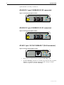
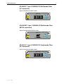
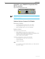
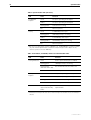
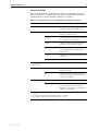
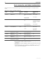
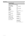
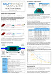
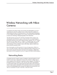
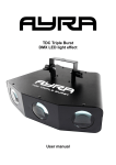
UPLINK MODULE
HARDWARE REFERENCE
S i m p ly c o n n e c t i n g t h e wo r l d
Uplink Module Hardware Reference
Document Number C613-03026-00 REV F.
Copyright © 1999-2001 Allied Telesyn International, Corp.
19800 North Creek Parkway, Suite 200, Bothell, WA 98011, USA.
All rights reserved. No part of this publication may be reproduced without prior written
permission from Allied Telesyn.
Allied Telesyn International, Corp. reserves the right to make changes in specifications
and other information contained in this document without prior written notice. The
information provided herein is subject to change without notice. In no event shall Allied
Telesyn be liable for any incidental, special, indirect, or consequential damages
whatsoever, including but not limited to lost profits, arising out of or related to this
manual or the information contained herein, even if Allied Telesyn has been advised of,
known, or should have known, the possibility of such damages.
All trademarks are the property of their respective owners.
Contents
Models Covered By This Reference .................................................................... 4
Why You Should Read This Reference ............................................................... 4
Where To Find More Information ...................................................................... 4
Compatible Switch Units ................................................................................... 5
Hardware Description ....................................................................................... 5
Uplink Module Overview ............................................................................ 5
AT-A35/SX 1-port 1000BASE-SX (SC connector) ......................................... 6
AT-A35/LX 1-port 1000BASE-LX (SC connector) .......................................... 6
AT-A39 1-port 10/100/1000BASE-T (RJ-45 connector) ................................ 6
AT-A40/SC 1-port 100BASE-FX Multimode Fibre
(SC connector) ..................................................................................... 7
AT-A40/MT 1-port 100BASE-FX Multimode Fibre
(MT-RJ connector) ................................................................................ 7
AT-A41/SC 1-port 100BASE-FX Singlemode Fibre
(SC connector) ..................................................................................... 7
AT-A41/MT 1-port 100BASE-FX Singlemode Fibre
(MT-RJ connector) ................................................................................ 8
Hardware Features Common To All Models ................................................ 8
Troubleshooting ................................................................................................ 9
Fault indicators and what they mean .......................................................... 9
Port, Connector, and Cable Combinations ...................................................... 13
Contacting Us ................................................................................................. 14
4
Uplink Module
Models Covered By This Reference
This Hardware Reference includes information on the following models:
■
AT-A35/SX
■
AT-A35/LX
■
AT-A39/T
■
AT-A40/SC
■
AT-A40/MT
■
AT-A41/SC
■
AT-A41/MT
The latest Hardware Reference can be found at www.alliedtelesyn.co.nz/
support/support.html.
Why You Should Read This Reference
This Reference has been developed to familiarise you with the hardware
features of Uplink Modules. The Reference provides information that will
assist you with the process of installing and maintaining Uplink Modules.
This Reference does not cover software configuration or physical installation procedures.
For information on software, refer to the Software Reference for your switch unit. For
information on installing an Uplink Module, refer to the Uplink Module Quick Install
Guide. These documents can be found on the CD-ROM bundled with your switch unit,
or at www.alliedtelesyn.co.nz/support/support.html.
Where To Find More Information
There are several sources of further information.
Information on Uplink Modules:
■
The Uplink Module Quick Install Guide, which outlines the procedure for
installing an Uplink Module; and the Hardware Reference for your switch
unit, which provides detailed information on the unit’s hardware features.
Information on Switches and Switching Routers:
■
The Hardware Reference for your switch or switching router, which provides
detailed information on the switch unit and its hardware features.
■
The Software Reference for your switch or switching router, which provides
detailed information on configuring the switch unit and its software.
■
The User Guide for your switch or switching router, which provides an
introduction to the switch unit’s Graphical User Interface and its Layer 2
switching features.
C613-03026-00 REV F
Hardware Reference
5
Information on other expansion options for the AR800 and Rapier Series:
■
The Network Service Module Quick Install Guide, which outlines the
procedure for installing an NSM; and the Network Service Module Hardware
Reference, which provides detailed information on NSMs.
■
The Port Interface Card Quick Install Guide, which outlines the procedure for
installing PICs; and the Port Interface Card Hardware Reference, which
provides detailed information on PICs.
All of these documents can be found on the Documentation and Tools CDROM bundled with each Switch or Switching Router, or at
www.alliedtelesyn.co.nz/support/support.html.
Compatible Switch Units
This section lists all uplink module models, and indicates which switches each
model can be installed in.
•
AT-A35/SX: All Rapier Switches, Rapier i switches, and AR800
Modular Switching Routers
•
AT-A35/LX: All Rapier Switches, Rapier i switches, and AR800
Modular Switching Routers
•
AT-A39/T: All Rapier Switches, Rapier i switches, and AR800 Modular
Switching Routers
•
AT-A40/SC: Rapier G6 and G6F switches and all Rapier i switches
•
AT-A40/MT: Rapier G6 and G6F switches and all Rapier i switches
•
AT-A41/SC: Rapier G6 and G6F switches and all Rapier i switches
•
AT-A41/MT: Rapier G6 and G6F switches and all Rapier i switches
Hardware Description
This section provides information on the hardware features of all Uplink
Module models.
Uplink Module Overview
Uplink Modules allow extra ports and port types to be added to the switch.
Uplink Modules also increase switching capacity by allowing switches to be
linked.
AT-82xx Expansion Modules are not compatible with AR800 Series Modular
Switching Routers or Rapier Switches. Attempting to install an AT-82xx
Expansion Module into an AR800 Series Modular Switching Router or Rapier
Switch may damage the Switch Unit and Expansion Module. If you are unsure
of a Module’s compatibility, before installing it, contact an authorised Allied
Telesyn distributor or reseller.
C613-03026-00 REV F
6
Uplink Module
Uplink Modules currently available are:
AT-A35/SX 1-port 1000BASE-SX (SC connector)
Figure 1: AT-A35-SX (SC) Uplink module.
AT-A35/SX
TX
DISABLED
RX
LINK
CLASS 1
LASER PRODUCT
DO NOT STARE
INTO BEAM
ACTIVITY
1000BASE-SX/SC
AT-A35/LX 1-port 1000BASE-LX (SC connector)
Figure 2: AT-A35-LX (SC) Uplink module.
AT-A35/LX
TX
DISABLED
RX
LINK
CLASS 1
LASER PRODUCT
DO NOT STARE
INTO BEAM
ACTIVITY
1000BASE-LX/SC
AT-A39 1-port 10/100/1000BASE-T (RJ-45 connector)
Figure 3: AT-A39-T (RJ-45) Uplink module.
AT-A39/T
1000M LINK 10 / 100M LINK
ACTIVITY
FULL DUP
10 / 100 / 1000BASE-T
COL
HALF DUP
•
Early versions of the AT-A39/T operate at 1000 Mbps only
•
10/100/1000 Mbps operation is available only if the AT-A39/T Uplink
Module is installed in a Rapier G6, Rapier G6F or Rapier i model,
otherwise operation is fixed at 1000 Mbps
C613-03026-00 REV F
Hardware Reference
7
AT-A40/SC 1-port 100BASE-FX Multimode Fibre
(SC connector)
Figure 4: AT-A40-FX (SC) Uplink module.
AT-A40 / FX
TX
RX
100M LINK
FAULT
ACTIVITY
CLASS 1
LASER PRODUCT
DO NOT STARE
INTO BEAM
FULL DUP
100BASE-FX / SC
HALF DUP
COL
AT-A40/MT 1-port 100BASE-FX Multimode Fibre
(MT-RJ connector)
Figure 5: AT-A40-FX (MT-RJ) Uplink module
AT-A40 / FX
100M LINK
FAULT
ACTIVITY
CLASS 1
LASER PRODUCT
DO NOT STARE
INTO BEAM
FULL DUP
100BASE-FX / MT-RJ
HALF DUP
COL
AT-A41/SC 1-port 100BASE-FX Singlemode Fibre
(SC connector)
Figure 6: AT-A41-FX (SC) Uplink module.
AT-A41 / FX
TX
100M LINK
FAULT
RX
ACTIVITY
CLASS 1
LASER PRODUCT
DO NOT STARE
INTO BEAM
FULL DUP
100BASE-FX / SC
C613-03026-00 REV F
HALF DUP
COL
8
Uplink Module
AT-A41/MT 1-port 100BASE-FX Singlemode Fibre
(MT-RJ connector)
Figure 7: AT-A41-FX (MT-RJ) Uplink module.
AT-A41 / FX
100M LINK
FAULT
ACTIVITY
CLASS 1
LASER PRODUCT
DO NOT STARE
INTO BEAM
FULL DUP
100BASE-FX / MT-RJ
HALF DUP
COL
More Uplink Modules are planned, check with your Authorised Allied Telesyn
distributor or reseller, or visit www.alliedtelesyn.co.nz, to see if any new Uplink Module
models have been released.
Hardware Features Common To All Models
Environmental Conditions
•
Operating temperature range: 0 to 40º C (32 to 104º F)
•
Storage temperature range: -25 to 70º C (-13 to 158º F)
•
Relative humidity range: 5 to 95% non-condensing
Regulatory Standards
AT-A35/SX, AT-A35/LX and AT-A39
•
EMC: CISPR22 class A, FCC class A, and VCCI class I
•
Immunity testing to EN50082 levels 2 (ESD), 3 (susceptibility), 4 (fast
transients), 5 (power surge), and 6 (RF immunity)
•
Safety: UL1950, CSA22.2, EN60950
AT-A40/SC, AT-A40/MT, AT-A41/SC and AT-A41/MT
•
EMC EN55022 class A, FCC class A, VCCI class I
•
Immunity EN55024
•
Safety UL, cUL and CE
LEDs
•
For a complete list of LEDs and their functions, see “LEDs and what
they mean”on page 9
C613-03026-00 REV F
Hardware Reference
9
Troubleshooting
This section provides information on how to detect and resolve the most
common problems that can cause Uplink Modules to malfunction.
Other sources of troubleshooting information are:
■
www.alliedtelesyn.co.nz.
■
The Software Reference for your switch unit.
Performing the following tasks will eliminate the most common faults.
1.
Check that the Uplink Module is correctly installed. See the Quick Install
Guide for your switch for a step by step guide to installing Uplink Modules.
2.
Make sure the power cord is securely connected to the switch unit and
power outlet.
3.
Check that the power supply voltage to the switch unit is stable.
4.
Check that the correct data cables are being used and that their connections
are secure.
5.
Make sure that other network devices are working properly.
6.
Use the SHOW INSTALL command to check that the latest software release
is loaded. See your switch unit’s Software Reference for more information
about obtaining the latest software release.
7.
If the switch unit is malfunctioning, reboot it by pressing the recessed Reset
button or entering the command RESTART REBOOT. Alternatively, power
OFF and ON the switch unit by disconnecting and reconnecting the main
power supply (including, if connected, the RPS power).
If the Uplink Module continues to malfunction, see “Some common problems
and how to solve them and follow” on page 12.
LEDs and what they mean
The following tables outline how Uplink Modules, AR800 Series Switching
Routers, Rapier Switches, and Rapier i Switches report faults and operational
activities.
Uplink Module LEDs
These LEDs are on the face-plates of respective Uplink Module models.
Table 8: Uplink Module LEDs (AT-A35/SX and AT-A35/LX).
LED
State
Function
Link
Green
The port is receiving light
Off
No link is present
Flashing Amber
Frames are being transmitted or received
through the port
Off
No activity is occurring
Activity
C613-03026-00 REV F
10
Uplink Module
Table 9: Uplink Module LEDs (AT-A39/T).
LED
State
Function
Full Dup/Half
Dup/Col
Green
The port is operating at full-duplex
Amber
The port is operating at half-duplex
Flashing amber
Collisions are occurring
Off
No link is present
Green
A 1000 Mbps link is open
Flashing green
1000 Mbps activity is occurring
Amber1
A 10/100 Mbps link is open
Flashing Amber1
10/100 Mbps activity is occurring
Off
No link is present
Activity
1. Early versions of the AT-A39/T operate at 1000 Mbps only. 10/100/1000 Mbps operation is available
only if the AT-A39/T Uplink Module is installed in a Rapier G6, Rapier G6F or Rapier i model,
otherwise operation is fixed at 1000 Mbps.
Table: 10 AT-A40/SC, AT-A40/MT, AT-A41/SC and AT-A41/MT LEDs1.
LED
State
Function
Activity/Link/Fault
Green
A link is open and the port is enabled
Flashing green
100 Mbps activity is occurring
Flashing amber
(and lower LED is Off)
The link has failed at the remote end
Off
No link is present
Green
The port is operating at full-duplex
Amber
The port is operating at half-duplex
Flashing amber
Collisions are occurring
Off
No link is present
Alternate flashing of
upper and lower LED,
amber
The switch does not support this model of
uplink module
Full Dup/Half
Dup/Col
Both LEDs
1. AT-A40 and AT-A41 Uplink Modules can be installed in Rapier G6 and G6F switches and all Rapier i
switches.
C613-03026-00 REV F
Hardware Reference
11
Switch-Unit LEDs
The following tables may be helpful when diagnosing possible operational
faults. These LEDs are on the front or rear panels of AR800 Series Modular
Switching Routers, Rapier Switches, and Rapier i Switches.
Table 11: System LEDs common to all AR800, Rapier, and Rapier i models.
LED
State
Function
Power
Green
The switch unit is receiving power and the
voltage is within the acceptable range
Fault
Red
The switch unit or its management
software is malfunctioning
1 flash
A switch-unit fan has failed. (The LEDs will
not indicate an RPS fan failure.)
3 flashes
If an RPS is connected, the switch-unit’s
PSU (Power Supply Unit) has failed
4 flashes
If RPS monitoring is enabled (using the SET
SYS RPSMON=ON command), the RPS
PSU has failed
5 flashes
If RPS monitoring is enabled, an RPS is not
connected
Off
Normal operation
Green
An RPS is connected to the switch unit
Green
An NSM is installed, is receiving power,
and is operational
Off
No NSM is installed, or the NSM is not
installed correctly (the switch unit has not
recognised the NSM)
Green
The NSM and PICs can be hot swapped
Off
The Hot Swap button must be pressed
before the NSM or PICs can be hot
swapped, or the software release does not
support hot swapping3
RPS1 (Redundant
Power Supply)
In use2 (Rear panel)
Swap2 (Rear panel)
1. DC Switch and Switching Router models do not have RPS connectors and their RPS LEDs will not
function.
2. Not included on the Rapier 48, G6, G6F/SX, G6F/LX, or G6F/MT.
2. Hot swapping is supported by software release 2.3.1 or later.
C613-03026-00 REV F
12
Uplink Module
Some common problems and how to solve them
Link/Activity LED on Any Port is Off
This can indicate:
■
A loose data cable.
■
The device at the other end of the connection is not working properly or is
turned off.
■
The data cable is not wired correctly.
■
The network administrator has manually disabled the port through the
software.
■
The port’s selected transmission mode does not match that of the attached
device.
Perform the following steps in sequence:
1.
Make sure the data cable connections are secure.
2.
Make sure the device at the other end of the connection is switched on and
working properly.
3.
Check that the data cable is wired correctly.
4.
If you can, log in and check the port status. See your switch unit’s Hardware
Reference for more information about logging in.
5.
If the port is Enabled, make sure the transmission speed matches that of the
connected device (auto-negotiating, full or half-duplex).
If the port is disabled, someone has used the software to manually disable it. You should
find out why the port was disabled before enabling it.
The Switch Unit’s Power LED is OFF
This can indicate:
■
A loose power cord.
■
A power supply failure.
Perform the following steps in sequence:
1.
Check that the power cord connection is secure.
2.
Ensure that the supply voltage is within the 110/240 VAC operational
range.
3.
If you can, log in and run diagnostics. See your switch unit’s Hardware
Reference for more information about logging in and running diagnostics.
C613-03026-00 REV F
Hardware Reference
13
Fault LED is On
This can indicate:
■
There is a problem with the switch unit or RPS PSU.
■
The switch unit or its management software is malfunctioning.
■
A software download has been unsuccessful.
■
A low power supply voltage.
■
Switch-unit overheating due to a fan failure or extreme ambient
temperature.
Perform the following steps in sequence:
1.
Check Table 11 on page 11 for descriptions of the flashing sequences and
what they mean.
2.
Reset the switch unit by pressing the recessed RESET button on the front
panel.
3.
If you were attempting to download software or manage the switch unit via
the RS-232 terminal Port, check that connections between the Terminal Port
and local terminal or PC are secure.
If you cannot access the switch unit’s software because of a faulty RS-232
Terminal Port connection, you can still manage the switch unit via Telnet or
SNMP until the problem is fixed.
C613-03026-00 REV F
4.
Unplug the switch unit and then plug it in again. If present, you will also
have to disconnect and reconnect the RPS unit.
5.
If you can, log in and run diagnostics. See your switch unit’s Hardware
Reference for more information about logging in and running diagnostics.
6.
Download the latest software release. See your switch unit’s Software
Reference for more information on how to obtain the latest software release.
14
Uplink Module
Port, Connector, and Cable Combinations
This section lists the recommended cable types and maximum cable lengths for each uplink module
model.
Table 12: Port, Connector, and cable Combinations.
Model
Port Type
Connector
Type
Cable Type1
Maximum Cable
Length
AT-A35/SX
1000BASE-SX
SC
50/125 micron multimode
fibre
550m (1,804ft)2
62.5/125 micron
multimode fibre
AT-A35/LX
AT-A39/T
1000BASE-LX
10100/1000BASE-T4
SC
RJ-45
275m (902ft)3
9/125 micron singlemode
fibre
3km (1.8mi)
Increasing to 10km (6mi)
if linking two 1000BASELX models
50/125 or 62.5/125
micron multimode fibre
550m (1804ft)2
CAT5
100 to 150m
CAT5E
(328 to 492ft)
200m (656ft)
AT-A40/SC
100BASE-FX
(Multimode fibre, 1300nM)
SC
50/125 or 62.5/125
micron multimode fibre
2km
AT-A40/MT
100BASE-FX
(Multimode fibre, 1300nM)
MT-RJ
50/125 or 62.5/125
micron multimode fibre
2km
AT-A41/SC
100BASE-FX
(Singlemode fibre, 1300nM)
SC
9/125 micron singlemode
fibre
15km
AT-A41/MT
100BASE-FX
(Singlemode fibre, 1300nM)
MT-RJ
9/125 micron singlemode
fibre
15km
1. Refer to the IEEE 802.3 Standards for further cable information.
2. Assumes a fibre optic cable rating of 500 Mhz/Km. (Maximum cable length is 500m at a cable rating
of 400 Mhz/Km.)
3. Assumes a fibre optic cable rating of 200 Mhz/Km. (Maximum cable length is 220m at a cable rating
of160 Mhz/Km.)
4. Early versions of the AT-A39/T operate at 1000 Mbps only. 10/100/1000 Mbps operation is available
only if the AT-A39/T Uplink Module is installed in a Rapier G6, Rapier G6F or Rapier i model,
otherwise operation is fixed at 1000 Mbps.
C613-03026-00 REV F
Hardware Reference
15
Contacting Us
Allied Telesyn Offices and Locations
UNITED KINGDOM
Tel: (+44) 1235 442500
Fax: (+44) 1235 442590
SWEDEN
Tel: 08 131414
NORWAY
Tel: 2211 1181
DENMARK
Tel: 3332 3006
FRANCE
Tel: (+33) 01 60 92 15 25
Fax: (+33) 01 69 28 37 49
BELGIUM
Tel: (+32) 2 481 60 60
Fax: (+32) 2 463 17 06
GERMANY
Tel: (+49) 30 435 90 00
Fax: (+49) 30 435 706 50
GERMANY - SOUTH
Tel: (+49) 8161 99 060
Fax: (+49) 8161 99 0622
EAST EUROPE - AUSTRIA
Tel: (+43) 1 8762441
Fax: (+43) 1 8762572
ITALY
Tel: (+39) 02 416047
Fax: (+39) 02 419282
SPAIN
Tel: (+34) 91 5591055
Fax: (+34) 91 5592644
U.S.A.
Fax: (425) 489-9191
http://www.alliedtelesyn.com
CANADA
Tel: (905) 709-7444
Fax: (905) 709-7400
LATIN AMERICA
Tel: 1-425-481-3852
Fax: 1-425-489-9191
SINGAPORE
Tel: (+65) 383-3832
Fax: (+65) 383-3830
AUSTRALIA
Tel: (+61) 2-9438-5111
Fax: (+61) 2-9438-496
NEW ZEALAND
Tel: (+64) 3 339 3000
Fax: (+64)3 339 3001
http://www.alliedtelesyn.co.nz
C613-03026-00 REV F