1
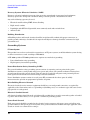
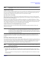
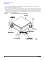
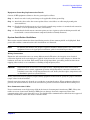
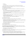
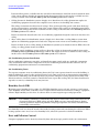
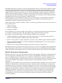
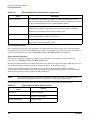
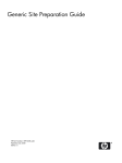
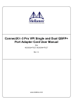
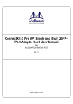
HP 9000 rp3410 and HP 9000 rp3440
Site Preparation Guide
HP 9000 rp3410 and HP 9000 rp3440
Manufacturing Part Number: A7137-96005
Fifth Edition
April 2005
U.S.A.
© Copyright 2004-2005 Hewlett-Packard Development Company, L.P..
Legal Notices
Copyright Notices. © Copyright 2004-2005 Hewlett-Packard Development Company, L.P.
The information contained herein is subject to change without notice.
The only warranties for HP products and services are set forth in the express warranty statements
accompanying such products and services. Nothing herein should be construed as constituting an additional
warranty. HP shall not be liable for technical or editorial errors or omissions contained herein.
2
Contents
1. System Specifications
System Configuration . . . . . . . . . . . . . . . . . . . . . . . . . . . . . . . . . . . . . . . . . . . . . . . . . . . . . . . . . . . . . . . .
Dimensions and Weights . . . . . . . . . . . . . . . . . . . . . . . . . . . . . . . . . . . . . . . . . . . . . . . . . . . . . . . . . . . . . .
Component Dimensions . . . . . . . . . . . . . . . . . . . . . . . . . . . . . . . . . . . . . . . . . . . . . . . . . . . . . . . . . . . . .
Grounding. . . . . . . . . . . . . . . . . . . . . . . . . . . . . . . . . . . . . . . . . . . . . . . . . . . . . . . . . . . . . . . . . . . . . . . . . .
Electrical Specifications. . . . . . . . . . . . . . . . . . . . . . . . . . . . . . . . . . . . . . . . . . . . . . . . . . . . . . . . . . . . . . .
AC Power Cords . . . . . . . . . . . . . . . . . . . . . . . . . . . . . . . . . . . . . . . . . . . . . . . . . . . . . . . . . . . . . . . . . . .
Circuit Breaker . . . . . . . . . . . . . . . . . . . . . . . . . . . . . . . . . . . . . . . . . . . . . . . . . . . . . . . . . . . . . . . . . . . .
AC Power Specifications . . . . . . . . . . . . . . . . . . . . . . . . . . . . . . . . . . . . . . . . . . . . . . . . . . . . . . . . . . . . .
Power Consumption and Cooling . . . . . . . . . . . . . . . . . . . . . . . . . . . . . . . . . . . . . . . . . . . . . . . . . . . . . .
Environmental Specifications . . . . . . . . . . . . . . . . . . . . . . . . . . . . . . . . . . . . . . . . . . . . . . . . . . . . . . . . . .
11
13
13
14
15
15
15
15
16
18
2. General Site Preparation Guidelines
Electrical Factors . . . . . . . . . . . . . . . . . . . . . . . . . . . . . . . . . . . . . . . . . . . . . . . . . . . . . . . . . . . . . . . . . . . .
Computer Room Safety. . . . . . . . . . . . . . . . . . . . . . . . . . . . . . . . . . . . . . . . . . . . . . . . . . . . . . . . . . . . . .
Power Consumption . . . . . . . . . . . . . . . . . . . . . . . . . . . . . . . . . . . . . . . . . . . . . . . . . . . . . . . . . . . . . . . .
Electrical Load Requirements (Circuit Breaker Sizing). . . . . . . . . . . . . . . . . . . . . . . . . . . . . . . . . . . .
Power Quality . . . . . . . . . . . . . . . . . . . . . . . . . . . . . . . . . . . . . . . . . . . . . . . . . . . . . . . . . . . . . . . . . . . . .
Distribution Hardware . . . . . . . . . . . . . . . . . . . . . . . . . . . . . . . . . . . . . . . . . . . . . . . . . . . . . . . . . . . . . .
Grounding Systems. . . . . . . . . . . . . . . . . . . . . . . . . . . . . . . . . . . . . . . . . . . . . . . . . . . . . . . . . . . . . . . . .
System Installation Guidelines . . . . . . . . . . . . . . . . . . . . . . . . . . . . . . . . . . . . . . . . . . . . . . . . . . . . . . .
Environmental Elements. . . . . . . . . . . . . . . . . . . . . . . . . . . . . . . . . . . . . . . . . . . . . . . . . . . . . . . . . . . . . .
Computer Room Preparation . . . . . . . . . . . . . . . . . . . . . . . . . . . . . . . . . . . . . . . . . . . . . . . . . . . . . . . . .
Cooling Requirements . . . . . . . . . . . . . . . . . . . . . . . . . . . . . . . . . . . . . . . . . . . . . . . . . . . . . . . . . . . . . .
Humidity Level (RH) . . . . . . . . . . . . . . . . . . . . . . . . . . . . . . . . . . . . . . . . . . . . . . . . . . . . . . . . . . . . . . .
Dust and Pollution Control . . . . . . . . . . . . . . . . . . . . . . . . . . . . . . . . . . . . . . . . . . . . . . . . . . . . . . . . . .
Metallic Particulate Contamination . . . . . . . . . . . . . . . . . . . . . . . . . . . . . . . . . . . . . . . . . . . . . . . . . . .
Electrostatic Discharge (ESD) Prevention . . . . . . . . . . . . . . . . . . . . . . . . . . . . . . . . . . . . . . . . . . . . . .
Acoustics . . . . . . . . . . . . . . . . . . . . . . . . . . . . . . . . . . . . . . . . . . . . . . . . . . . . . . . . . . . . . . . . . . . . . . . . .
Facility Characteristics . . . . . . . . . . . . . . . . . . . . . . . . . . . . . . . . . . . . . . . . . . . . . . . . . . . . . . . . . . . . . . .
Floor Loading . . . . . . . . . . . . . . . . . . . . . . . . . . . . . . . . . . . . . . . . . . . . . . . . . . . . . . . . . . . . . . . . . . . . .
Windows . . . . . . . . . . . . . . . . . . . . . . . . . . . . . . . . . . . . . . . . . . . . . . . . . . . . . . . . . . . . . . . . . . . . . . . . .
Space Requirements. . . . . . . . . . . . . . . . . . . . . . . . . . . . . . . . . . . . . . . . . . . . . . . . . . . . . . . . . . . . . . . . . .
Delivery Space Requirements . . . . . . . . . . . . . . . . . . . . . . . . . . . . . . . . . . . . . . . . . . . . . . . . . . . . . . . .
Operational Space Requirements . . . . . . . . . . . . . . . . . . . . . . . . . . . . . . . . . . . . . . . . . . . . . . . . . . . . .
Floor Plan Grid . . . . . . . . . . . . . . . . . . . . . . . . . . . . . . . . . . . . . . . . . . . . . . . . . . . . . . . . . . . . . . . . . . . .
Conversion Factors and Formulas. . . . . . . . . . . . . . . . . . . . . . . . . . . . . . . . . . . . . . . . . . . . . . . . . . . . . . .
Conversion Factors . . . . . . . . . . . . . . . . . . . . . . . . . . . . . . . . . . . . . . . . . . . . . . . . . . . . . . . . . . . . . . . . .
Formulas . . . . . . . . . . . . . . . . . . . . . . . . . . . . . . . . . . . . . . . . . . . . . . . . . . . . . . . . . . . . . . . . . . . . . . . . .
Sample of an Installation Schedule . . . . . . . . . . . . . . . . . . . . . . . . . . . . . . . . . . . . . . . . . . . . . . . . . . . . .
Sample Site Inspection Checklist . . . . . . . . . . . . . . . . . . . . . . . . . . . . . . . . . . . . . . . . . . . . . . . . . . . . . . .
Delivery Survey . . . . . . . . . . . . . . . . . . . . . . . . . . . . . . . . . . . . . . . . . . . . . . . . . . . . . . . . . . . . . . . . . . . . .
Information to Collect Before You Contact Support. . . . . . . . . . . . . . . . . . . . . . . . . . . . . . . . . . . . . . . . .
19
19
20
20
20
21
22
25
26
26
26
28
28
29
30
30
31
31
33
34
34
34
34
36
36
36
37
38
41
44
Glossary . . . . . . . . . . . . . . . . . . . . . . . . . . . . . . . . . . . . . . . . . . . . . . . . . . . . . . . . . . . . . . . . . . . . 45
3
Contents
Index . . . . . . . . . . . . . . . . . . . . . . . . . . . . . . . . . . . . . . . . . . . . . . . . . . . . . . . . . . . . . . . . . . . . . . . 47
4
Figures
Figure 1-1. HP 9000 rp3410 and HP 9000 rp3440 Server . . . . . . . . . . . . . . . . . . . . . . . . . . . . . . . . .
Figure 2-1. Raised Floor Metal Strip Ground System . . . . . . . . . . . . . . . . . . . . . . . . . . . . . . . . . . . .
Figure 2-2. Delivery Survey (Part 1) . . . . . . . . . . . . . . . . . . . . . . . . . . . . . . . . . . . . . . . . . . . . . . . . . .
Figure 2-3. Delivery Survey (Part 2) . . . . . . . . . . . . . . . . . . . . . . . . . . . . . . . . . . . . . . . . . . . . . . . . . .
11
24
42
43
5
Figures
6
Preface
This preface contains the following sections:
•
Intended Audience
•
What’s New?
•
Notational Conventions
•
Reader Comments and Feedback
•
Related Information
•
Printing History
Intended Audience
This document is intended to provide technical product and support information for authorized service
providers, customer system administrators, and HP support personnel.
What’s New?
•
The layout of this document was changed to improve usability.
Notational Conventions
The following notational conventions are used in this publication.
WARNING
A warning lists requirements that you must meet to avoid personal injury.
CAUTION
A caution provides information required to avoid losing data or avoid losing system
functionality.
NOTE
A note highlights useful information such as restrictions, recommendations, or important
details about HP product features.
•
Commands and options are represented using this font.
•
Text that you type exactly as shown is represented using this font.
•
Text to be replaced with text that you supply is represented using this font.
Example:
“Enter the ls -l filename command” means you must replace filename with your own text.
•
Keyboard keys and graphical interface items (such as buttons, tabs, and menu items) are represented using this
font.
Examples:
The Control key, the OK button, the General tab, the Options menu.
•
Menu —> Submenu represents a menu selection you can perform.
7
Example:
“Select the Partition —> Create Partition action” means you must select the Create Partition menu item from
the Partition menu.
•
Example screen output is represented using this font.
Reader Comments and Feedback
HP welcomes your feedback on this publication. Please address your comments to
[email protected] and note that you will not receive an immediate reply. All comments are
appreciated.
Related Information
You can find other information on HP server hardware management, Microsoft® Windows®, and diagnostic
support tools in the following publications.
Web Site for HP Technical Documentation:
http://docs.hp.com
The main Web site for HP technical documentation is http://docs.hp.com, which has complete information
available for free.
Server Hardware Information:
http://docs.hp.com/hpux/hw/
The http://docs.hp.com/hpux/hw/ Web site is the systems hardware portion of the docs.hp.com and
provides HP nPartition server hardware management details, including site preparation, installation, and
more.
Windows Operating System Information
You can find information about administration of the Microsoft® Windows® operating system at the
following Web sites, among others:
•
http://docs.hp.com/windows_nt/
•
http://www.microsoft.com/technet/
Diagnostics and Event Monitoring: Hardware Support Tools
Complete information about HP’s hardware support tools, including online and offline diagnostics and event
monitoring tools, is at the http://docs.hp.com/hpux/diag/ Web site. This site has manuals, tutorials,
FAQs, and other reference material.
Web Site for HP Technical Support:
http://us-support2.external.hp.com
HP’s IT resource center Web site at http://us-support2.external.hp.com/ provides comprehensive
support information for IT professionals on a wide variety of topics, including software, hardware, and
networking.
Books about HP-UX Published by Prentice Hall
The http://www.hp.com/hpbooks/ Web site lists the HP books that Prentice Hall currently publishes, such
as HP-UX books including:
8
•
HP-UX 11i System Administration Handbook
http://www.hp.com/hpbooks/prentice/ptr_0130600814.html
•
HP-UX Virtual Partitions
http://www.hp.com/hpbooks/prentice/ptr_0130352128.html
HP Books are available worldwide through bookstores, online booksellers, and office and computer stores.
Printing History
The Printing History below identifies the edition dates of this manual. Updates are made to this publication
on an unscheduled, as needed, basis. The updates will consist of a complete replacement manual and
pertinent on-line or CD-ROM documentation.
Fifth Edition
........................................................
June 2004
Sixth Edition
........................................................
April 2005
9
10
1 System Specifications
System Configuration
Figure 1-1
HP 9000 rp3410 and HP 9000 rp3440 Server
The following table lists the system specification for the HP 9000 rp3410 and HP 9000 rp3440 server.
Table 1-1
Component
Hardware Specifications
rp3410
rp3440
Microprocessors
One dual processor module with one or
two PA RISC processors enabled. Each
processor is 800 MHz/1.5 MB cache
with 32 MB or 64 MB L2 cache
One or two dual processor modules each
containing two PA RISC processors.
Each processor is 800 MHz/1.5 MB cache
or 1 GHz/1.5 MB with 32 MB or 64 MB
L2 cache
Memory
Supports up to 12 double data rate
(DDR) registered ECC memory, in
PC2100 DIMMs. Maximum memory
capacity is 6 GB. Supported DDR
DIMM sizes: 256 MB, 512 MB, and 1
GB
Supports up to 12 double data rate
(DDR) registered ECC Memory, in
PC2100 DIMMs. Maximum memory
capacity is 32 GB if 4 GB DIMMs are
used. Supported DDR DIMM sizes:
256 MB, 512 MB, 1 GB, 2 GB, and 4 GB
HDDs
Three 36 GB, 15K RPM Ultra320 SCSI
hot-plug disks or
Three 73 GB, 15K RPM Ultra320 SCSI
hot-plug disks or
Three 146 GB, 10K RPM Ultra320
SCSI hot-plug disks
Three 36 GB, 15K RPM Ultra320 SCSI
hot-plug disks or
Three 73 GB, 15K RPM Ultra320 SCSI
hot-plug disks or
Three 146 GB, 10K RPM Ultra320 SCSI
hot-plug disks
Chapter 1
11
System Specifications
System Configuration
Table 1-1
Hardware Specifications (Continued)
Component
rp3410
rp3440
SCSI
Integrated Ultra-3 SCSI dual channel
controller; 80 MB/s transfer rate with
one internal 68-pin connector and one
external 68-pin connector
Integrated Ultra-3 SCSI dual channel
controller; 80 MB/s transfer rate with
one internal 68-pin connector and one
external 68-pin connector
LAN
PCI GB, fast ethernet controller
PCI GB, fast ethernet controller
PCI slots
Two 64-bit PCI-X slots, 133 MHz, 3.3V
slots
Four 64-bit PCI-X slots, 133 MHz, 3.3V
slots
Core I/O
One serial port, four USB 2.0 ports,
integrated RJ-45 LAN on iLO
manageability card
One serial port, four USB 2.0 ports,
integrated RJ-45 LAN on iLO
manageability card
DVD-ROM
None
IDE interface; 48x speed
External storage
Optional
Optional
Power supply
One 650W power supply. You can
install a second power supply to provide
redundant (N+1) capability
One 650W power supply. You can install
a second power supply to provide
redundant (N+1) capability
12
Chapter 1
System Specifications
Dimensions and Weights
Dimensions and Weights
This section provides dimensions and weights of HP 9000 rp3410 and HP 9000 rp3440 server components.
Component Dimensions
Table 1-2
Server Component Dimensions
Dimension
Value
Rack dimensions (depth x width x height)
67.9 cm (26.8 in.) maximum x 48.3 cm (19.0 in.)
x 8.6 cm (3.4 in.)
Tower dimensions (depth x width x height)
67.5 cm (26.6 in.) x 29.5 cm (11.6 in.) x 49.4 cm
(19.5 in.)
Rack weight
Min: 17.5 kg (38.6 lb.)
Max: 22.2 kg (49.0 lb.)
Tower weight
Min: 22.4 kg (49.4 lb.)
Max: 25.5 kg (56.3 lb.)
Tower footprint
0.2 m2 (2.1 sq. ft.)
Rack units
2U
Chapter 1
13
System Specifications
Grounding
Grounding
The site building shall provide a safety ground or protective earth for each AC service entrance to all cabinets.
Install a PE (protective earthing) conductor that is identical in size, insulation material, and thickness to the
branch-circuit supply conductors. The PE conductor must be green with yellow stripes. The earthing
conductor is to be connected from the unit to the building installation earth or, if supplied by a separately
derived system, at the supply transformer or motor-generator set grounding point.
14
Chapter 1
System Specifications
Electrical Specifications
Electrical Specifications
This section provides electrical specifications for your HP server.
AC Power Cords
Table 1-3 lists the various power cables available for use with the HP 9000 rp3410 and HP 9000 rp3440
servers.
Table 1-3
Power Cords
Part Number
Description
Country
8120-5341
Pwr Crd C15/S Africa 2.5m BLACK CA ASSY 917
S. Africa
8120-1351
Pwr Crd C13/BS-1363 2.3m BLACK CA ASSY 900
UK & HK & Singapore
8120-1369
Pwr Crd C13/AS-3112 2.0m GRAY CA ASSY 901
Australia
8120-1689
Pwr Crd C13/CEE 7 2.0m BLACK CA ASSY 902
Europe
8120-2104
Pwr Crd C13/SEV 12 2.0m BLACK CA ASSY 906
Swiss
8120-6814
Pwr-Crd OPT-912 3-COND 2.25-M-LG 912
Denmark
8120-0698
Pwr Crd C13/6-15P 0.0m BLACK CA ASSY 904 / 918
N. Amer 250V / Japan
8120-6800
Pwr-Crd OPT-919 3-COND 2.3-M-LG 919
Israel
8120-8390
Pwr Crd C15/CEI 23-16 2.5m BLACK CA ASSY 920
Argentina
8120-8389
Pwr Crd C15/CEI 23-16 2.5m BLACK CA ASSY 921
Chile
8120-8376
Pwr Crd C13/GB-1002 2.236m GRAY CA ASSY 922
China
8121-0668
Pwr-Crd OPT-927 3-COND 2.3-M-LG FLNT 927
S. America
8120-6514
Jumper cord
Circuit Breaker
The marked electrical for the HP server is 7.2 amps. The recommended circuit breaker size is 12 amps per
line cord (2 maximum) for North America. For countries outside North America, consult the local electrical
authority that has jurisdiction for the recommended circuit breaker size.
AC Power Specifications
Available power (output) is the maximum DC power that the power supply can supply to the system.
Maximum input power is what the power supply requires from the AC line to deliver the maximum DC
output (given worst case efficiency and max loading).
Chapter 1
15
System Specifications
Electrical Specifications
Maximum input current is the worst case or highest current given the lowest input voltage and the maximum
input power.
Table 1-4
System Power Specifications
Parameter
Peak
(15 sec)
Total Rating
Max. per PCI-X Sockets
64-bit, 133 MHz
Input voltage
100 – 240 VAC
Off
Off
Input current (max)
7.2A at 115 VAC or
3.6A at 220 VAC
Off
Off
Input frequency
50 to 60 Hz
Off
Off
Measured input power
560W
Off
Off
Available power (output)
650W
Off
85W total for PCI sockets
Max current at +12V
49A
0.5A
Off
Max current at –12V
0.35A
Off
0.1A
Max current at +3.3V
34A
Off
4.6A
Max current at +5V
18A
31A
3A
Max current at +3.3V
standby
3.5A
Off
Off
If an overload triggers the power supply overload protection, the system is immediately powered off. To reset
the power supply unit perform the following steps:
1. Disconnect the power cord.
2. Determine what caused the overload by contacting a HP support representative.
3. Reconnect the power cord, then reboot the system.
If an overload occurs twice, there is an undetected short circuit somewhere.
When you use the front panel’s power button to turn off the workstation, power consumption falls below the
low power consumption, but doesn’t reach zero. To reach zero power consumption in “off ” mode, either unplug
the workstation or use a power block with a switch.
Power Consumption and Cooling
Power consumption for a typical server is 600W/2050 Btu/h. The power consumptions listed in the following
table are valid for a standard configuration as shipped (one 1 GHz processor, 6 GB of memory, 650W power
supply, three hard disk drives, one graphics card, one LVD SCSI card).
All information in this section is based on primary power consumptions.
Table 1-5
Additional Component Power Consumption
Additional Component
Power Consumption
Processor
130W
443.6 Btu/h
SCSI hard disk drive (with I/O access)
23W
78.4 Btu/h
16
Chapter 1
System Specifications
Electrical Specifications
Table 1-5
Additional Component Power Consumption (Continued)
Additional Component
Power Consumption
SCSI hard disk (idle)
16W
54.5 Btu/h
PCI card
10W to 25W
34.12 Btu/h to 85.30 Btu/h
Chapter 1
17
System Specifications
Environmental Specifications
Environmental Specifications
This section provides the temperature and humidity requirements, noise emission, and air flow specifications
for the HP server.
Operating temperature and humidity ranges might vary depending on the installed mass storage devices.
High humidity levels can cause improper disk operation. Low humidity levels can aggravate static electricity
problems and cause excessive wear of the disk surface.
Table 1-6
Environmental Specifications (system processing unit with hard disk)
Parameter
Value
Operating temperature
+5°C to +35°C (+40°F to +95°F)
Storage temperature
–40°C to +70°C (–40°F to +158°F)
Over-temperature shutdown
+40°C (+104°F)
Operating humidity
15% to 80% relative (noncondensing)
Storage humidity
8% to 85% relative (noncondensing)
Acoustic noise emission (ISO 7779)
Sound power levela
Tower system
Typical configuration (disk idle)b
LwA = 5.1 BA
Maximum configuration (disk idle)c
LwA = 5.4 BA
Maximum configuration (disk active)c
LwA = 6.2 BA
Rack system
Typical configuration (disk idle)b
LwA = 6.4 BA
Maximum configuration (disk idle)c
LwA = 6.4 BA
Maximum configuration (disk active)c
LwA = 7.2 BA
Operating altitude
3048m (10,000 ft.) max
Storage altitude
4600m (15,000 ft.) max
a. Typical configuration at room temperature (25°C).
b. One processor enabled, one or two SCSI hard disk drives and less than 8 GB of memory.
c. Two dual processors, one or two SCSI hard disk drives and less than 8 GB of memory.
18
Chapter 1
2 General Site Preparation Guidelines
The following information provides general principles and practices to consider before the installation or
operation of the HP 9000 rp3410 and HP 9000 rp3440 servers.
Electrical Factors
NOTE
Electrical practices and suggestions in this guide are based on North American practices. For
regions and areas outside North America, local electrical codes will take precedence over North
American electrical codes.
An example would be the recommendation that the PE (Protective Earthing) conductor be
green with yellow stripes. This requirement is a North American directive and does not
override the local code requirements for a region or area outside North America.
Local authority has jurisdiction (LAHJ) and should make the final decision regarding
adherence to region-specific or area-specific electrical codes and guidelines.
Proper design and installation of a power distribution system for a HP 9000 rp3410 or HP 9000 rp3440 server
requires specialized skills. Those responsible for this task must have a thorough knowledge and
understanding of appropriate electrical codes and the limitations of the power systems for computer and data
processing equipment.
In general, a well-designed power distribution system exceeds the requirements of most electrical codes. A
good design, when coupled with proper installation practices, produces the most trouble-free operation.
A detailed discussion of power distribution system design and installation is beyond the scope of this
information. However, electrical factors relating to power distribution system design and installation must be
considered during the site preparation process.
The electrical factors discussed in this section are:
•
Computer room safety
•
Power consumption
•
Electrical load requirements (circuit breaker sizing)
•
Power quality
•
Distribution hardware
•
System installation guidelines
Computer Room Safety
Inside the computer room, fire protection and adequate lighting (for equipment servicing) are important
safety considerations. Federal and local safety codes govern computer installations.
Fire Protection
The National Fire Protection Association’s Standard for the Protection of Electronic Computer Data
Processing Equipment, NFPA 75, contains information on safety monitoring equipment for computer rooms.
Chapter 2
19
General Site Preparation Guidelines
Electrical Factors
Most computer room installations are equipped with the following fire protection devices:
•
Smoke detectors
•
Fire and temperature alarms
•
Fire extinguishing system
Additional safety devices are:
•
Circuit breakers
•
An emergency power cutoff switch
•
Devices specific to the geographic location, such as, earthquake protection
Lighting Requirements for Equipment Servicing
Adequate lighting and utility outlets in a computer room reduce the possibility of accidents during equipment
servicing. Safer servicing is also more efficient and, therefore, less costly.
For example, adequate lighting reduces the chances of connector damage when cables are installed or
removed.
The minimum recommended illumination level is 70 foot-candles (756 lumens per square meter) when the
light level is measured at 30 inches (76.2 cm) above the floor.
Working Space for Server Access
The recommended working space for performing maintenance on the server is three feet (91.4 cm). The work
space shall permit at least a 90° opening of equipment doors or hinged panels. When planning for the working
space area, consider whether access to the server will be at the front, side, or rear of the server.
Power Consumption
When determining power requirements, you must consider any peripheral equipment that will be installed
during initial installation or as a later update. Refer to the applicable documentation for such devices to
determine the power required to support these devices.
Electrical Load Requirements (Circuit Breaker Sizing)
NOTE
Local authority has jurisdiction (LAHJ) and should make the final decision regarding
adherence to country-specific electrical codes and guidelines.
It is good practice to derate power distribution systems for one or more of the following reasons:
•
To avoid nuisance tripping from load shifts or power transients, circuit protection devices should never be
run above 80% of their root-mean-square (RMS) current ratings
•
Safety agencies derate most power connectors to 80% of their RMS current ratings
Power Quality
The HP 9000 rp3410 and HP 9000 rp3440 servers are designed to operate over a wide range of voltages and
frequencies. The server is tested and shown to comply with EMC Specification EN50082. However, damage
can occur if these ranges are exceeded. Severe electrical disturbances can exceed the design specifications of
the equipment.
20
Chapter 2
General Site Preparation Guidelines
Electrical Factors
Sources of Voltage Fluctuations
Voltage fluctuations, sometimes called glitches, affect the quality of electrical power. Common sources of these
disturbances are:
•
Fluctuations occurring within the facility’s distribution system
•
Utility service low-voltage conditions (such as sags or brownouts)
•
Wide and rapid variations in input voltage levels
•
Wide and rapid variations in input power frequency
•
Electrical storms
•
Large inductive sources (such as motors and welders)
•
Faults in the distribution system wiring (such as loose connections)
•
Microwave, radar, radio, or cell phone transmissions
Power System Protection
You can protect the HP 9000 rp3410 and HP 9000 rp3440 servers from the sources of many of these electrical
disturbances by using:
•
A dedicated power distribution system
•
Power conditioning equipment
•
Over- and under-voltage detection and protection circuits
•
Screening to cancel out the effects of undesirable transmissions
•
Lightning arresters on power cables to protect equipment against electrical storms
Precautions have been taken during power distribution system design to provide immunity to power outages
of less than one cycle. However, testing cannot conclusively rule out loss of service. Therefore, adherence to
the following guidelines provides the best possible performance of power distribution systems for HP
computer equipment:
•
Dedicated power source—Isolates a HP 9000 rp3410 or HP 9000 rp3440 server power distribution system
from other circuits in the facility
•
Missing-phase and low-voltage detectors—Shuts equipment down automatically when a severe power
disruption occurs. For peripheral equipment, these devices are recommended but optional
•
Online uninterruptible power supply (UPS)—Keeps input voltage to devices constant and should be
considered if outages of one-half cycle or more are common. Refer to qualified contractors or consultants
for each situation
Distribution Hardware
This section describes wire selection and the types of raceways (electrical conduits) used in the distribution
system.
Wire Selection
Use copper conductors instead of aluminum; aluminum’s coefficient of expansion differs significantly from
that of other metals used in power hardware. Because of this difference, aluminum conductors can cause
connector hardware to work loose, overheat, and fail.
Chapter 2
21
General Site Preparation Guidelines
Electrical Factors
Raceway Systems (Electrical Conduits) (LAHJ)
Raceways (electrical conduits) form part of the protective ground path for personnel and equipment.
Raceways protect the wiring from accidental damage and also provide a heatsink for the wires.
Any of the following types may be used:
•
Electrical metallic tubing (EMT) thin-wall tubing
•
Rigid (metal) conduit
•
Liquidtight with RFI shield grounded (most commonly used under raised floors)
•
Armored cable
Building Distribution
All building feeders and branch circuitry should be in rigid metallic conduit with proper connectors (to
provide ground continuity). Conduit that is exposed and subject to damage should be constructed of rigid
galvanized steel.
Grounding Systems
IT Power System
This product has not been evaluated for connection to an IT power system (an AC distribution system having
no direct connection to earth according to IEC 60950).
A HP 9000 rp3410 or HP 9000 rp3440 server requires two methods of grounding:
•
Power distribution safety grounding
•
High frequency intercabinet grounding
Power Distribution Safety Grounding (LAHJ)
The power distribution safety grounding system consists of connecting various points in the power
distribution system to earth ground using green (green and yellow) wire ground conductors. Having these
ground connections tied to metal chassis parts that may be touched by computer room personnel protects
them against shock hazard from current leakage and fault conditions.
Power distribution systems consist of several parts. HP recommends that these parts be solidly
interconnected to provide an equipotential ground to all points.
Main Building Electrical Ground
The main electrical service entrance equipment should have an earth ground connection, as required by
applicable codes. Connections such as a grounding rod, building steel, or a conductive type cold water service
pipe provide an earth ground.
Electrical Conduit Ground
All electrical conduits should be made of rigid metallic conduit that is securely connected together or bonded
to panels and electrical boxes, so as to provide a continuous grounding system.
Power Panel Ground
Each power panel should be grounded to the electrical service entrance with green (green and yellow) wire
ground conductors. The green (green and yellow) wire ground conductors should be sized per applicable codes
(based on circuit over current device ratings).
22
Chapter 2
General Site Preparation Guidelines
Electrical Factors
NOTE
The green wire ground conductor mentioned above may be a black wire marked with green
tape (LAHJ).
Computer Safety Ground
Ground all computer equipment with the green (green and yellow) wire included in the branch circuitry. The
green (green and yellow) wire ground conductors should be connected to the appropriate power panel and
should be sized per applicable codes (based on circuit over current device ratings).
Dual Power Source Grounding
When dual power sources are utilized, strong consideration should be given to measure voltage potentials.
The use of dual power might create an electrical potential that can be harmful to personnel and might cause
performance issues for the equipment.
Dual power sources might originate from two different transformers or two different UPS devices. Voltage
potentials from ground pin to ground pin of these sources should be measured and verified to be at or near 0.0
volts. Voltage levels that deviate or are measured above 3.0 volts should be further investigated. Increased
voltages might be harmful to personnel, and should be further investigated.
Cabinet Performance Grounding (High Frequency Ground)
Signal interconnects between system cabinets require high frequency ground return paths. Connect all
cabinets to site ground.
NOTE
In some cases power distribution system green (green and yellow) wire ground conductors are
too long and inductive to provide adequate high frequency ground return paths. Therefore, a
ground strap (customer-supplied) should be used for connecting the system cabinet to the site
grounding grid (customer-supplied). When connecting this ground, ensure that the raised floor
is properly grounded for high frequency.
Power panels located in close proximity to the computer equipment should also be connected to the site
grounding grid. Methods of providing a sufficiently high frequency ground grid are described in the next
sections.
Raised Floor “High Frequency Noise” Grounding
If a raised floor system is used, install a complete signal grounding grid for maintaining equal potential over
a broad band of frequencies. The grounding grid should be connected to the equipment cabinet and electrical
service entrance ground at multiple connection points using a minimum #6 AWG (16mm2) wire ground
conductor. The following Figure 3-1 illustrates a metallic strip grounding system.
NOTE
Regardless of the grounding connection method used, the raised floor should be grounded as an
absolute safety minimum.
HP recommends the following approaches:
•
Excellent—Add a grounding grid to the subfloor. The grounding grid should be made of copper strips
mounted to the subfloor. The strips should be 0.032 in. (0.08 cm) thick and a minimum of 3.0 in. (8.0 cm)
wide
Connect each pedestal to four strips using 1/4 in. (6.0 mm) bolts tightened to the manufacturer’s torque
recommendation
Chapter 2
23
General Site Preparation Guidelines
Electrical Factors
•
Better—A grounded #6 AWG minimum copper wire grid mechanically clamped to floor pedestals and
properly bonded to the building or site ground
•
Good—Use the raised floor structure as a ground grid. In this case, the floor must be designed as a ground
grid with bolted down stringers and corrosion resistive plating (to provide low resistance and attachment
points for connection to service entrance ground and HP computer equipment). The use of conductive floor
tiles with this style of grid further enhances ground performance. The structure needs to be mechanically
bonded to a known good ground point
Figure 2-1
24
Raised Floor Metal Strip Ground System
Chapter 2
General Site Preparation Guidelines
Electrical Factors
Equipment Grounding Implementation Details
Connect all HP equipment cabinets to the site ground grid as follows:
Step 1. Attach one end of each ground strap to the applicable cabinet ground lug.
Step 2. Attach the other end to the nearest pedestal base (raised floor) or cable trough ground point
(nonraised floor).
Step 3. Check that the braid contact on each end of the ground strap consists of a terminal and connection
hardware (a 1/4-in. [6.0-mm] bolt, nuts, and washers).
Step 4. Check that the braid contact connection points are free of paint or other insulating material and
treated with a contact enhancement compound (similar to Burndy Penetrox).
System Installation Guidelines
This section contains information about installation practices. Some common pitfalls are highlighted. Both
power cable and data communications cable installations are discussed.
NOTE
In domestic installations, the proper receptacles should be installed prior to the arrival of HP
equipment. Refer to the appropriate installation guide for installation procedures.
Wiring Connections
Expansion and contraction rates vary among different metals. Therefore, the integrity of an electrical
connection depends on the restraining force applied. Connections that are too tight compress or deform the
hardware and cause it to weaken. This usually leads to high impedance, preventing circuit breakers from
tripping when needed, or can contribute to a buildup of high frequency noise.
CAUTION
Connections that are too loose or too tight can have a high impedance that causes serious
problems, such as erratic equipment operation. A high impedance connection overheats and
sometimes causes fire or high temperatures that can destroy hard-to-replace components such
as distribution panels or system bus bars.
Wiring connections must be properly torqued. Many equipment manufacturers specify the proper connection
torque values for their hardware.
Ground connections must only be made on a conductive, nonpainted surface. When equipment vibration is
present, lock washers must be used on all connections to prevent connection hardware from working loose.
Data Communications Cables
Power transformers create high-energy fields in the form of electromagnetic interference (EMI). Heavy foot
traffic can create electrostatic discharge (ESD) that can damage electronic components. Route data
communications cables away from these areas. Use shielded data communications cables that meet approved
industry standards to reduce the effects of external fields.
Chapter 2
25
General Site Preparation Guidelines
Environmental Elements
Environmental Elements
The following environmental elements can affect a HP 9000 rp3410 or HP 9000 rp3440 server installation:
•
Computer room preparation
•
Cooling requirements
•
Humidity level
•
Air conditioning ducts
•
Dust and pollution control
•
Electrostatic discharge (ESD) prevention
•
Acoustics (noise reduction)
Computer Room Preparation
The following guidelines are recommended when preparing a computer room for a HP 9000 rp3410 or HP
9000 rp3440 server:
•
Locate the computer room away from the exterior walls of the building to avoid the heat gain from
windows and exterior wall surfaces
•
When exterior windows are unavoidable, use windows that are double- or triple-glazed and shaded to
prevent direct sunlight from entering the computer room
•
Maintain the computer room at a positive pressure relative to surrounding spaces
•
Use a vapor barrier installed around the entire computer room envelope to restrain moisture migration
•
Caulk and vapor seal all pipes and cables that penetrate the envelope
•
Use at least a 12-inch raised floor system for minimum favorable room air distribution system (underfloor
distribution)
•
Ensure a minimum clearance of 12 inches between the top of the server cabinet and the ceiling to allow
for return air flow and ensure that all ceiling tiles are in place
•
Allow 18 inches (or local code minimum clearance) from the top of the server cabinet to the fire sprinkler
heads
Cooling Requirements
Air conditioning equipment requirements and recommendations are described in the following sections.
Basic Air Conditioning Equipment Requirements
The cooling capacity of the installed air conditioning equipment for the computer room should be sufficient to
offset the computer equipment dissipation loads, as well as any space envelope heat gain. This equipment
should include:
•
Air filtration
•
Cooling or dehumidification
•
Humidification
26
Chapter 2
General Site Preparation Guidelines
Environmental Elements
•
Reheating
•
Air distribution
•
System controls adequate to maintain the computer room within specified operating ranges
Lighting and personnel must also be included. For example, a person dissipates about 450 BTUs per hour
while performing a typical computer room task.
Air Conditioning System Guidelines
The following guidelines are recommended when designing an air conditioning system and selecting the
necessary equipment:
•
The air conditioning system that serves the computer room should be capable of operating 24 hours a day,
365 days a year. It should also be independent of other systems in the building
•
Consider the long-term value of HP 9000 rp3410 and HP 9000 rp3440 server availability, redundant air
conditioning equipment, or capacity
•
The system should be capable of handling any future HP 9000 rp3410 and HP 9000 rp3440 server
expansion
•
Air conditioning equipment air filters should have a minimum rating of 45% (based on ASHRAE
Standard 52-76, Dust Spot Efficiency Test)
•
Introduce only enough outside air into the system to meet building code requirements (for human
occupancy) and to maintain a positive air pressure in the computer room
Air Conditioning System Types
The following three air conditioning system types are listed in order of recommendation:
•
Complete self-contained package unit(s) with remote condenser(s). These systems are available with up or
down discharge and are usually located in the computer room
•
Chilled water package unit with remote chilled water plant. These systems are available with up or down
discharge and are usually located in the computer room
•
Central station air handling units with remote refrigeration equipment. These systems are usually
located outside the computer room
Basic Air Distribution Systems
A basic air distribution system includes supply air and return air.
An air distribution system should be zoned to deliver an adequate amount of supply air to the cooling air
intake vents of the HP 9000 rp3410 and HP 9000 rp3440 server equipment cabinets. Supply air temperature
should be maintained within the following parameters:
•
Ceiling supply system—From 55°F (12.8°C) to 60°F (15.6°C)
•
Floor supply system—At least 60°F (15.6°C)
If a ceiling plenum return air system or a ducted ceiling return air system is used, the return air grill(s) in the
ceiling should be above the exhaust area or the exhaust row.
The following three types of air distribution system are listed in order of recommendation:
•
Underfloor air distribution system—Downflow air conditioning equipment located on the raised floor of
the computer room uses the cavity beneath the raised floor as a plenum for the supply air
Return air from an underfloor air distribution system can be ducted return air (DRA) above the ceiling
Chapter 2
27
General Site Preparation Guidelines
Environmental Elements
Perforated floor panels (available from the raised floor manufacturer) should be located around the front
of the system cabinets. Supply air emitted though the perforated floor panels is then available near the
cooling air intake vents of the HP 9000 rp3410 and HP 9000 rp3440 server cabinets
•
Ceiling plenum air distribution system—Supply air is ducted into the ceiling plenum from upflow air
conditioning equipment located in the computer room or from an air handling unit (remote)
The ceiling construction should resist air leakage. Place perforated ceiling panels (with down discharge
air flow characteristics) around the front of the system cabinets. The supply air emitted downward from
the perforated ceiling panels is then available near the cooling air intake vents of the HP 9000 rp3410 and
HP 9000 rp3440 server cabinets
Return air should be ducted back to the air conditioning equipment though the return air duct above the
ceiling
•
Above ceiling ducted air distribution system—Supply air is ducted into a ceiling diffuser system from
upflow air conditioning equipment located in the computer room or from an air handling unit (remote)
Return air from an above ceiling ducted air distribution system may be ducted return air (DRA) above the
ceiling, or ceiling plenum return air (CPRA)
Adjust the supply air diffuser system grilles to direct the cooling air downward around the front of the
HP 9000 rp3410 and HP 9000 rp3440 server cabinets. The supply air is then available near the cooling air
intake vents of the HP 9000 rp3410 and HP 9000 rp3440 server cabinets
Air Conditioning System Installation
All air conditioning equipment, materials, and installation must comply with any applicable construction
codes. Installation of the various components of the air conditioning system must also conform to the air
conditioning equipment manufacturer’s recommendations.
Air Conditioning Ducts
Use separate computer room air conditioning duct work. If it is not separate from the rest of the building, it
might be difficult to control cooling and air pressure levels. Duct work seals are important for maintaining a
balanced air conditioning system and high static air pressure. Adequate cooling capacity means little if the
direction and rate of air flow cannot be controlled because of poor duct sealing. Also, the ducts should not be
exposed to warm air, or humidity levels may increase.
Humidity Level (RH)
Maintain proper humidity levels at 40 to 55% RH. High humidity causes galvanic actions to occur between
some dissimilar metals. This eventually causes a high resistance between connections, leading to equipment
failures. High humidity can also have an adverse affect on some magnetic tapes and paper media.
CAUTION
Low humidity contributes to undesirably high levels of electrostatic charges. This increases the
electrostatic discharge (ESD) voltage potential. ESD can cause component damage during
servicing operations. Paper feed problems on high-speed printers are usually encountered in
low-humidity environments.
Low humidity levels are often the result of the facility heating system and occur during the cold season. Most
heating systems cause air to have a low humidity level, unless the system has a built-in humidifier.
Dust and Pollution Control
Computer equipment can be adversely affected by dust and microscopic particles in the site environment.
28
Chapter 2
General Site Preparation Guidelines
Environmental Elements
Specifically, disk drives, tape drives, and some other mechanical devices can have bearing failures resulting
from airborne abrasive particles. Dust may also blanket electronic components like printed circuit boards,
causing premature failure due to excess heat or humidity build up on the boards. Other failures to power
supplies and other electronic components can be caused by metallically conductive particles, including zinc
whiskers. These metallic particles are conductive and can short circuit electronic components. Use every
effort to ensure that the environment is as dust- and particulate-free as possible. See the following heading
titled Metallic Particulate Contamination for additional details.
Smaller particles can pass through some filters, and over a period of time, cause problems in mechanical
parts. Small dust particles can be prevented from entering the computer room by maintaining the air
conditioning system at a high static air pressure level.
Other sources of dust, metallic, conductive, abrasive, or microscopic particles can be present. Some sources of
these particulates are:
•
Subfloor shedding
•
Raised floor shedding
•
Ceiling tile shedding
These particulates are not always visible to the naked eye. A good check to determine their possible presence
is to check the underside of the tiles. The tile should be shiny, galvanized, and free from rust.
The computer room should be kept clean. The following guidelines are recommended:
•
Smoking—Establish a no-smoking policy. Cigarette smoke particles are eight times larger than the
clearance between disk drive read/write heads and the disk surface
•
Printer—Locate printers and paper products in a separate room to eliminate paper particulate problems
•
Eating or drinking—Establish a no-eating or drinking policy. Spilled liquids can cause short circuits in
equipment such as keyboards
•
Tile floors—Use a dust-absorbent cloth mop rather than a dry mop to clean tile floors
Special precautions are necessary if the computer room is near a source of air pollution. Some air pollutants,
especially hydrogen sulfide (H2S), are not only unpleasant but corrosive as well. Hydrogen sulfide damages
wiring and delicate sound equipment. The use of activated charcoal filters reduces this form of air pollution.
Metallic Particulate Contamination
Metallic particulates can be especially harmful around electronic equipment. This type of contamination may
enter the data center environment from a variety of sources, including but not limited to raised floor tiles,
worn air conditioning parts, heating ducts, rotor brushes in vacuum cleaners, or printer component wear.
Because metallic particulates conduct electricity, they have an increased potential for creating short circuits
in electronic equipment. This problem is exaggerated by the increasingly dense circuitry of electronic
equipment.
Over time, very fine whiskers of pure metal can form on electroplated zinc, cadmium, or tin surfaces. If these
whiskers are disturbed, they may break off and become airborne, possibly causing failures or operational
interruptions. For over 50 years, the electronics industry has been aware of the relatively rare but possible
threat posed by metallic particulate contamination. During recent years, a growing concern has developed in
computer rooms where these conductive contaminants are formed on the bottom of some raised floor tiles.
Although this problem is relatively rare, it may be an issue within your computer room. Since metallic
contamination can cause permanent or intermittent failures on your electronic equipment, HP strongly
recommends that your site be evaluated for metallic particulate contamination before installation of
electronic equipment.
Chapter 2
29
General Site Preparation Guidelines
Environmental Elements
Electrostatic Discharge (ESD) Prevention
Static charges (voltage levels) occur when objects are separated or rubbed together. The voltage level of a
static charge is determined by the following factors:
•
Types of materials
•
Relative humidity
•
Rate of change or separation
Table 2-1
Effect of Humidity on ESD Charge Levels
Personnel Activitya
Humidityb and Charge Levels (voltages)c
26%
32%
40%
50%
Person walking across a linoleum floor
6,150V
5,750V
4,625V
3,700V
Person walking across a carpeted floor
18,450V
17,250V
13,875V
11,100V
Person getting up from a plastic chair
24,600V
23,000V
18,500V
14,800V
a. Source: B.A. Unger, Electrostatic Discharge Failures of Semiconductor Devices (Bell Laboratories,
1981).
b. For the same relative humidity level, a high rate of airflow produces higher static charges than a
low airflow rate.
c. Some data in this table has been extrapolated.
Static Protection Measures
Follow these precautions to minimize possible ESD-induced failures in the computer room:
•
Maintain recommended humidity level and airflow rates in the computer room
•
Install conductive flooring (conductive adhesive must be used when laying tiles)
•
Use conductive wax if waxed floors are necessary
•
Ensure that all equipment and flooring are properly grounded and are at the same ground potential
•
Use conductive tables and chairs
•
Use a grounded wrist strap (or other grounding method) when handling circuit boards
•
Store spare electronic modules in antistatic containers
Acoustics
Computer equipment and air conditioning blowers cause computer rooms to be noisy. Ambient noise level in a
computer room can be reduced as follows:
•
Dropped ceiling—Cover with a commercial grade of fire-resistant, acoustic rated, fiberglass ceiling tile
•
Sound deadening—Cover the walls with curtains or other sound deadening material
•
Removable partitions—Use foam rubber models for most effectiveness
30
Chapter 2
General Site Preparation Guidelines
Facility Characteristics
Facility Characteristics
This section contains information about facility characteristics that must be considered for the installation or
operation of a HP 9000 rp3410 and HP 9000 rp3440 server. Facility characteristics are:
•
Floor loading
•
Windows
•
Altitude effects
Floor Loading
The computer room floor must be able to support the total weight of the installed HP 9000 rp3410 and HP
9000 rp3440 server as well as the weight of the individual cabinets as they are moved into position.
Floor loading is usually not an issue in nonraised floor installations. The information presented in this section
is directed toward raised floor installations.
NOTE
An appropriate floor system consultant should verify any floor system under consideration for a
HP 9000 rp3410 or HP 9000 rp3440 server installation.
Raised Floor Loading
Raised floor loading is a function of the manufacturer’s load specification and the positioning of the
equipment relative to the raised floor grid. While HP cannot assume responsibility for determining the
suitability of a particular raised floor system, it does provide information and illustrations for the customer or
local agencies to determine installation requirements.
The following guidelines are recommended:
•
Because many raised floor systems do not have grid stringers between floor stands, the lateral support for
the floor stands depends on adjacent panels being in place. To avoid compromising this type of floor
system while gaining under-floor access, remove only one floor panel at a time
•
Larger floor grids (bigger panels) are generally rated for lighter loads
CAUTION
Do not position or install any equipment cabinets on the raised floor system until you have
carefully examined it to verify that it is adequate to support the appropriate installation.
Floor Loading Terms.
The following table lists floor loading terms and definitions.
Table 2-2
Floor Loading Term Definitions
Term
Definition
Dead load
The weight of the raised panel floor system, including the understructure.
Expressed in lb/ft2 (kg/m2)
Live load
The load that the floor system can safely support. Expressed in lb/ft2 (kg/m2)
Chapter 2
31
General Site Preparation Guidelines
Facility Characteristics
Table 2-2
Floor Loading Term Definitions (Continued)
Term
Definition
Concentrated load
The load that a floor panel can support on a 1-in2 (6.45-cm2) area at the
panel’s weakest point (typically the center of the panel), without the surface
of the panel deflecting more than a predetermined amount
Ultimate load
The maximum load (per floor panel) that the floor system can support
without failure. Failure expressed by floor panel(s) breaking or bending
Ultimate load is usually stated as load per floor panel
Rolling load
The load a floor panel can support (without failure) when a wheel of specified
diameter and width is rolled across the panel
Average floor load
Computed by dividing total equipment weight by the area of its footprint.
This value is expressed in lb/ft2 (kg/m2)
Average Floor Loading
The average floor load value is not appropriate for addressing raised floor ratings at the floor grid spacing
level. However, it is useful for determining floor loading at the building level, such as the area of solid floor or
span of raised floor tiles covered by the HP 9000 rp3410 or HP 9000 rp3440 server footprint.
Typical Raised Floor Site
This section contains an example of a computer room raised floor system that is satisfactory for the
installation of a HP 9000 rp3410 or HP 9000 rp3440 server.
Based on specific information provided by HP, Tate Access Floors has approved its Series 800 all-steel access
floor with bolt-together stringers and 24 in. (61.0 cm) by 24 in. (61.0 cm) floor panels.
In the event that the flooring is being replaced or a new floor is being installed, Tate Access Floors
recommends its Series 1250 all-steel access floor with bolt-together stringers and 24-in. (61.0-cm) by 24-in.
(61.0-cm) floor panels be used to support the HP installation.
NOTE
If the specific floor being evaluated or considered is other than a Tate Series 800 floor, the
specific floor manufacturer must be contacted to evaluate the floor being used.
The following table lists specifications for the Tate Access Floors Series 800 raised floor system.
Table 2-3
Typical Raised Floor Specifications
Itema
Rating
Dead load
7 lb/ft2 (34.2 kg/m2)
Live load
313 lb/ft2 (1528.3 kg/m2)
Concentrated loadb
1250 lb (567 kg)
32
Chapter 2
General Site Preparation Guidelines
Facility Characteristics
Table 2-3
Typical Raised Floor Specifications (Continued)
Itema
Rating
Ultimate load
4,000 lb (1814 kg) per panel
Rolling load
400 lb (181 kg)
Average floor load
500 lb (227 kg)
a. From Table 2-2 on page 31
b. With 0.08 in (0.2 cm) of span maximum deflection
Windows
Avoid housing computers in a room with windows. Sunlight entering a computer room may cause problems.
Magnetic tape storage media is damaged if exposed to direct sunlight. Also, the heat generated by sunlight
places an additional load on the cooling system.
Chapter 2
33
General Site Preparation Guidelines
Space Requirements
Space Requirements
This section contains information about the space requirements for a HP 9000 rp3410 or HP 9000 rp3440
server. This data should be used as the basic guideline for space plan developments. Other factors, such as
airflow, lighting, and equipment space requirements must also be considered.
Delivery Space Requirements
There should be enough clearance to move equipment safely from the receiving area to the computer room.
Permanent obstructions, such as pillars or narrow doorways, can cause equipment damage.
Delivery plans should include the possible removal of walls or doors.
Operational Space Requirements
Other factors must be considered along with the basic equipment dimensions. Reduced airflow around
equipment causes overheating, which can lead to equipment failure. Therefore, the location and orientation of
air conditioning ducts, as well as airflow direction, are important. Obstructions to equipment intake or
exhaust airflow must be eliminated.
The locations of lighting fixtures and utility outlets affect servicing operations. Plan equipment layout to take
advantage of lighting and utility outlets. Do not forget to include clearance for opening and closing equipment
doors.
Clearance around the cabinets must be provided for proper cooling airflow through the equipment.
If other equipment is located so that it exhausts heated air near the cooling air intakes of the HP 9000 rp3410
and HP 9000 rp3440 server cabinets, larger space requirements are needed to keep ambient air intake to the
HP 9000 rp3410 and HP 9000 rp3440 server cabinets within the specified temperature and humidity ranges.
Space planning should also include the possible addition of equipment or other changes in space
requirements. Equipment layout plans should also include provisions for the following:
•
Channels or fixtures used for routing data cables and power cables
•
Access to air conditioning ducts, filters, lighting, and electrical power hardware
•
Power conditioning equipment
•
Cabinets for cleaning materials
•
Maintenance area and spare parts
Floor Plan Grid
A floor plan grid is used to plan the location of equipment in the computer room. In addition to its use for
planning, the floor plan grid should also be used when planning the locations of the following items:
•
Air conditioning vents
•
Lighting fixtures
•
Utility outlets
•
Doors
•
Access areas for power wiring and air conditioning filters
34
Chapter 2
General Site Preparation Guidelines
Space Requirements
•
Equipment cable routing
Chapter 2
35
General Site Preparation Guidelines
Conversion Factors and Formulas
Conversion Factors and Formulas
The conversion factors provided here are intended to ease data calculation for systems that do not conform
specifically to the configurations listed in this Site Preparation Guide. Listed below are the conversion factors
used in this document, as well as additional conversion factors which may be helpful in determining those
factors required for site planning.
Conversion Factors
•
Refrigeration
— 1 watt = .86 kcal/h
— 1 watt = 3.412 Btu/h
— 1 watt = 2.843 x 10⁻⁴ tons
— 1 ton = 200 Btu/min.
— 1 ton = 12,000 Btu/h
— 1 ton = 3,517.2W
•
Metric Equivalents
— 1 centimeter = 0.3937 in.
— 1 meter = 3.28 ft.
— 1 meter = 1.09 yds
— 1 in. = 2.54 cm
— 1 ft. = 0.305m
— 1 CFM = 1.7m3/h
•
kVA Conversions
Three phase
kVA = V × A × √3 ⁄
•
1000
Single phase
kVA = V × A ⁄
1000
Formulas
•
kVA = Voltage x Current (amps)
•
Watts = VA x PF
•
BTU = Watts x 3.41
36
Chapter 2
General Site Preparation Guidelines
Sample of an Installation Schedule
Sample of an Installation Schedule
The following schedule lists the sequence of events for a typical system installation:
•
60 days before installation
— Floor plan design completed and mailed to HP (if required to be an HP task)
•
30 days before installation
— Primary power and air conditioning installation completed
— Telephone and data cables installed
— Fire protection equipment installed
— Major facility changes completed
— Special delivery requirements defined
— Site inspection survey completed
— Delivery survey completed
— A signed copy of the site inspection and delivery survey mailed to HP
— Site inspection and predelivery coordination meeting arranged with an HP representative to review
the inspection checklist and arrange an installation schedule
•
7 days before installation
— Final check made with an HP site preparation specialist to resolve any last minute problems
NOTE
Chapter 2
Not all installations follow a schedule like the one noted above. Sometimes, a HP 9000 rp3410
or HP 9000 rp3440 server is purchased through another vendor, which can preclude a rigid
schedule. Other conditions could also prevent following this schedule. For those situations,
consider a milestone schedule.
•
Site Preparation—Schedule with the customer as soon as possible after the order is placed.
•
Site Verification—Schedule with the customer a minimum of one to two days before the
HP 9000 rp3410 or HP 9000 rp3440 server is scheduled to be installed.
37
General Site Preparation Guidelines
Sample Site Inspection Checklist
Sample Site Inspection Checklist
The following table lists the type of information needed in a site inspection.
Table 2-4
Customer and HP Information
Customer Information
Name:
Phone No:
Street Address:
City:
or
Town:
State or Province:
Country
Zip or postal code:
Primary customer contact:
Phone No.:
Secondary customer contact:
Phone No.:
Traffic coordinator:
Phone No.:
HP information
Sales representative:
Order No:
Representative making survey:
Date:
Scheduled delivery date:
The following table is an example of a site inspection checklist.
Table 2-5
Site Inspection Checklist
Please check either Yes or No. If No, include comment# or date
Comment or Date
Computer Room
No.
Area or condition
1.
Is there a completed floor plan?
2.
Is there adequate space for maintenance needs?
Front 36 in (91.4 cm) minimum, rear 36 in (91.4 cm)
minimum are recommended clearances
3.
Is access to the site or computer room restricted?
4.
Is the computer room structurally complete?
Expected date of completion?
5.
Is a raised floor installed and in good condition?
6.
Is the raised floor adequate for equipment loading?
7.
Are there channels or cutouts for cable routing?
38
Yes
No
Chapter 2
General Site Preparation Guidelines
Sample Site Inspection Checklist
Table 2-5
Site Inspection Checklist (Continued)
Please check either Yes or No. If No, include comment# or date
8.
Is there a remote console telephone line available with an
RJ11 jack?
9.
Is a telephone line available?
10.
Are customer supplied peripheral cables and LAN cables
available and of the proper type?
11.
Are floor tiles in good condition and properly braced?
12.
Is floor tile underside shiny or painted? If painted, judge
the need for particulate test
Comment or Date
Power and Lighting
No.
Area or condition
13.
Are lighting levels adequate for maintenance?
14.
Are there AC outlets available for servicing needs? (for
example, vacuuming)
15.
Does the input voltage correspond to equipment
specifications?
15A
Is dual source power used? If so, identify type(s) and
evaluate grounding.
16.
Does the input frequency correspond to equipment
specifications?
17.
Are lightning arrestors installed inside the building?
18.
Is power conditioning equipment installed?
19.
Is there a dedicated branch circuit for equipment?
20.
Is the dedicated branch circuit less than 250 feet (72.5
meters)?
21.
Are the input circuit breakers adequate for equipment
loads?
Yes
No
Yes
No
Safety
No.
Area or condition
22.
Is there an emergency power shut-off switch?
23.
Is there a telephone available for emergency purposes?
24.
Is there a fire protection system in the computer room?
25.
Is antistatic flooring installed?
Chapter 2
39
General Site Preparation Guidelines
Sample Site Inspection Checklist
Table 2-5
Site Inspection Checklist (Continued)
Please check either Yes or No. If No, include comment# or date
26.
Comment or Date
Are there any equipment servicing hazards
(loose ground wires, poor lighting, and so on)?
Cooling
No.
Area or condition
27.
Can cooling be maintained between 20°C and 55°C (up to
5,000 ft.)? Derate 1°C/1,000 ft. above 5,000 ft. and up to
10,000 ft.
28.
Can temperature changes be held to 10°C per hour with
tape media? Can temperature changes be held to 20°C per
hour without tape media?
29.
Can humidity level be maintained at 40% to 60% at 35°C
noncondensing?
30.
Are air conditioning filters installed and clean?
Yes
No
Yes
No
Storage
No.
Area or condition
31.
Are cabinets available for tape and disc media?
32.
Is shelving available for documentation?
Training
No.
Area or Condition
33.
Are personnel enrolled in the System Administrator’s
Course?
34.
Is on-site training required?
40
Chapter 2
General Site Preparation Guidelines
Delivery Survey
Delivery Survey
The delivery survey forms list delivery or installation requirements. If any of the items on the list apply, enter
the appropriate information in the areas provided on the form.
Special instructions or recommendations should be entered on the special instructions or recommendations
form, see Figure 3-2. The following list gives examples of special instructions or issues:
•
Packaging restrictions at the facility, such as size and weight limitations
•
Special delivery procedures
•
Special equipment required for installation, such as tracking or hoists
•
What time the facility is available for installation (after the equipment is unloaded)
•
Special security requirements applicable to the facility, such as security clearance
Chapter 2
41
General Site Preparation Guidelines
Delivery Survey
Figure 2-2
Delivery Survey (Part 1)
DELIVERY CHECKLIST
DOCK DELIVERY
Is dock large enough for a semitrailer?
Yes ___________ No ___________
Circle the location of the dock and give street name if different than address.
North
West
East
South
STREET DELIVERY
Circle the location of access door and list street name if different than address.
North
West
East
South
List height ___________ and width ___________ of access door.
List special permits (if required) for street delivery.
42
Permit type:
Agency obtained from:
______________________________________
______________________________________
______________________________________
______________________________________
Chapter 2
General Site Preparation Guidelines
Delivery Survey
Figure 2-3
Delivery Survey (Part 2)
ELEVATOR
Fill in the following information if an elevator is required to move equipment.
Capacity (lb or kg) ________________
Depth ________________
Height ________________
Width ________________
Height
Dept
Widt
STAIRS
Please list number of flights and stairway dimensions.
Number of flights _____________________
Number of flights _____________________
Width ______________________
Width ______________________
Width ______________________
Width ______________________
Widt
Chapter 2
Widt
43
General Site Preparation Guidelines
Information to Collect Before You Contact Support
Information to Collect Before You Contact Support
Before you contact HP support, you should:
Step 1. Check information on troubleshooting and attempt to solve the problem. Refer to “Troubleshooting”
in the Operation Guide for your system, available at http://docs.hp.com.
•
Note failure symptoms and error indications (LEDs and messages) by checking the SEL and
FPL logs
•
Try to determine precisely what did or did not happen
Step 2. Collect the following information:
•
The model number of your server (for example: rp3410 or rp3440)
•
The product number of your server. This can be found on the identification label, which is found
at the front of the unit (typically A7136A or A7137A, and so on)
•
The serial number of your server. This can be found on the identification label
Step 3. Become familiar with your system configuration:
•
Are you using the LAN, RS232, or web interface to monitor the server?
•
How many processors, DIMMs, and PCI cards have been installed?
•
What versions of processor, memory, and PCI cards are used and where are they installed?
•
What accessories are installed?
Step 4. Determine the following:
44
•
Which firmware versions are in use?
•
When did the problem start?
•
Have recent changes been made to the system?
•
Which operating system and version is in use?
Chapter 2
Glossary
A-B
Apparent power A value of power for AC circuits
that is calculated as the product of RMS current
times RMS voltage, without taking the power factor
into account.
ASHRAE Standard 52-76 Industry standard for
air filtration efficiency set forth by the American
Society of Heating, Refrigerating, and
Air-Conditioning Engineers, Inc.
ASL Above sea level.
board A printed circuit assembly (PCA). Also called
a card or adapter.
Btu/h The abbreviation for British thermal units.
The amount of heat required to raise one pound of
water one degree fahrenheit per hour, a common
measure of heat transfer rate.
C
CompactPCI The newest specification for
PCI-based industrial computers is called
CompactPCI. It is electrically a superset of desktop
PCI with a different physical form factor. See
http://www.picmg.org for details.
CFM The abbreviation for cubic feet per minute,
commonly used to measure the rate of air flow in an
air conditioning system.
Chilled water system A type of air conditioning
system that has no refrigerant in the unit itself. The
refrigerant is contained in a chiller, which is located
remotely. The chiller cools water, which is piped to
the air conditioner to cool the space.
D-K
Dehumidification The process of removing
moisture from the air within a critical space.
Derate To lower the rated capability of an electrical
or mechanical apparatus.
Downflow Refers to a type of air conditioning
system that discharges air downward, directly
beneath a raised floor, commonly found in computer
rooms and modern office spaces.
Glossary
EIA unit The Electronic Industries Association
(EIA) defines this unit of measurement to be 1.75
inches in height. So then, 1U equals 1.75 inches (1U
equals 44.45 mm).
Humidification The process of adding moisture to
the air within a critical space.
Inrush current The peak current flowing into a
power supply the instant AC power is applied. This
peak is usually much higher than the typical input
current due to the charging of the input filter
capacitors. When switching power supplies are first
turned on, they present high initial currents as a
result of filter capacitor impedance. These large
filter capacitors act like a short circuit, producing an
immediate inrush surge current with a fast rise
time. The peak inrush current can be several orders
of magnitude greater than the supply’s typical
current.
KVA Abbreviation for kilovolt-amperes. (1,000 x
volt-amperes).
L-N
Latent cooling capacity An air conditioning
system’s capability to remove heat from the air.
Leakage current A term relating to current
flowing between the AC supply wires and earth
ground. The term does not necessarily denote a fault
condition. In power supplies, leakage current
usually refers to the 60 Hertz current, which flows
through the EMI filter capacitors that are connected
between the AC lines and ground.
Maximum input current The operating current of
the product equal to the maximum load divided by
the minimum input voltage.
NEBS All electronic equipment has the potential to
interfere with other electronic equipment.
Interference can be caused by electromagnetic
radiation, the grounding system, the electrical
power connection, excessive heat, or blocking the
natural airflow, and connecting wires or cables. The
FCC (Federal Communications Commission)
regulates a portion of this problem through Part 15
of their rules and regulations. Even more stringent
than the FCC Part 15 requirements, Network
Equipment Building Standards (NEBS) covers a
large range of requirements including criteria for
personnel safety, protection of property, and
45
Glossary
PCA
operational continuity. The documents cover both
physical requirements including: Space Planning,
Temperature, Humidity, Fire, Earthquake,
Vibration, Transportation, Acoustical, Air Quality
and Illumination; and electrical criteria including:
Electrostatic Discharge (ESD), Electromagnetic
Interference (EMI), Lightning and AC Power Fault,
Steady State Power Induction, Corrosion, DC
Potential Difference, Electrical Safety and Bonding
and Grounding.
Tonnage The unit of measure used in air
conditioning to describe the heating or cooling
capacity of a system. One ton of heat represents the
amount of heat needed to melt one ton (2,000 lbs.) of
ice in one hour. 12,000 Btu/hr equals one ton of heat.
O-R
Typical input current The operating current of
the product measured using a typical load and target
voltage.
PCA Abbreviation for Printed Circuit Assembly
also referred to as a Printed Circuit Board (PCB).
PCI Currently, the most popular local I/O bus, the
Peripheral Component Interconnect (PCI) bus was
developed by Intel and introduced in 1993.
PICMG A consortium of companies involved in
utilizing PCI for embedded applications. The PCI
Industrial Computer Manufacturers Group (PICMG)
controls the PICMG specification.
Power factor The ratio of true power to apparent
power in an AC circuit. In power conversion
technology, power factor is used in conjunction with
describing the AC input current to the power supply.
RMS Root-mean-square (rms) refers to the most
common mathematical method of defining the
effective voltage or current of an AC wave. To
determine rms value, three mathematical operations
are carried out on the function representing the AC
waveform: (1) The square of the waveform function
(usually a sine wave) is determined. (2) The function
resulting from step (1) is averaged over time. (3) The
square root of the function resulting from step (2) is
found.
S-T
Theoretical maximum power consumption
True power In an AC circuit, true power is the
actual power consumed. It is distinguished from
apparent power by eliminating the reactive power
component that may be present.
Typical power consumption Represents the
expected power consumption of a given
configuration. The typical value is the approximate
power consumption that a customer will most likely
experience and can use for power budgeting
purposes.
U-Z
Vapor seal A vapor seal is an essential part of
preventing moisture infiltration into or migration
out of a critical space, such as a data processing
center or other room that contains sensitive
electronic instrumentation. Essentially, a vapor seal
is a barrier that prevents air, moisture, and
contaminants from migrating through tiny cracks or
pores in the walls, floor, and ceiling into the critical
space. Vapor barriers may be created using plastic
film, vapor-retardant paint, vinyl wall coverings and
vinyl floor systems, in combination with careful
sealing of all openings (doors and windows) into the
room.
Watt A unit of electricity consumption representing
the product of amperage and voltage. When the
power requirement of a product is listed in watts,
you can convert to amps by dividing the wattage by
the voltage. (e.g., 1200 watts divided by 120 volts is
10 amps.
Represents the maximum wattage of a given
configuration, assuming worst-case conditions
(thermal tolerances, workloads, and so forth) on all
system components. It is extremely unlikely that
any customer will experience this level of power
consumption.
46
Glossary
Index
A
air conditioning
system recommendations, 27
air conditioning ducts, 28
air distribution system
room space return air, 27
Altitude, 18
floor-plan grid, 34
operational space requirements, 34
typical raised floor site, 32
windows, 33
fire protection, 19
floor loading
raised floor, 31
B
basic air conditioning equipment requirements, 26
basic air distribution systems, 27
G
grounding systems, 22
electrical conduit ground, 22
C
circuit breaker, 15
computer room safety
fire protection, 19
cooling requirements, 26
H
Humidity, 18
humidity level, 28
D
data communications cables, 25
dimensions and weights, 13
ducts, air conditioning, 28
E
electrical and environmental guidelines
air distribution system, 27
computer equipment grounds, 23
computer room safety
fire protection, 19
dust and pollution control, 28
electrical conduit ground, 22
grounding systems, 22
lighting requirements, 20
main building electrical ground, 22, 23
power distribution safety grounding, 22
power panel grounds, 22
power quality, 20
sources of electrical disturbances, 21
system installation guidelines, 25
electrical specifications, 15
environmental elements, 26
acoustics, 30
air conditioning equipment requirements, 26
air conditioning recommendations, 27
air distribution systems, 27
computer room considerations, 26
cooling requirements, 26
dust and pollution control, 28
electrostatic discharge
prevention, 30
humidity level, 28
static protection measures, 30
F
facility characteristics, 31
facility guidelines
characteristics, 31
floor loading terms, 31
K
Keystone system
environmental elements, 26
power system protection, 21
typical installation schedule, 37
M
main building electrical ground, 22
P
Power, 15, 16
power distribution hardware, 21
power distribution safety grounding, 22
power distribution system
distribution hardware, 21
power quality, 20
power system protection, 21
R
raised floor
ground system, illustrated, 24
S
sources of electrical disturbances, 21
space requirements, 34
delivery space requirements, 34
system installation guidelines, 25
data communications cables, 25
wiring connections, 25
T
Temperature, 18
typical installation schedule, 37
W
wiring
connections, 25
47