1
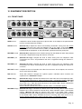
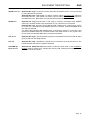
MACROTEL
D1 - D2
DIGITAL TELEPHONE HYBRIDS
User Manual
(Rel. 1.3)
Via Caduti Di Sabbiuno 6/F - 40011 Anzola Emilia - Bologna - Italy
Tel. +39 051 736555 – 051 736154 - Fax. +39 051 736170
e-mail: [email protected] - web site: www.axeltechnology.com
This manual is for use with the following products :
Macrotel D1
Macrotel D2
Axel Technology SRL
All Rights Reserved
Revision 1.3, October 2005
Via Caduti Di Sabbiuno 6/F - 40011 Anzola Emilia - Bologna - Italy
Tel. +39 051 736555 – + 39 051 736154
Fax. +39 051 736170
e-mail: [email protected] - web site: www.axeltechnology.com
Information in this document is subject to change without notice and does not represent a commitment on the part of the
vendor. This manual images could differ a bit from the equipment actual design. Axel Technology SRL shall not be liable for
any loss or damage whatsoever arising from the use of information or any error contained in this manual.
No part of this manual may be reproduced or transmitted in any form or by any means, electronic or mechanical, including
photocopying, recording, information storage and retrieval systems, for any purpose other than the purchaser’s personal use,
without the express written permission of Axel Technology SRL.
Pag. 2
TABLE OF CONTENTS
ENG
1 TABLE OF CONTENTS
1
2
TABLE OF CONTENTS ........................................................................................................................ 3
INTRODUCTION................................................................................................................................... 4
2.1
WHAT IS A TELEPHONE HYBRID ................................................................................................. 4
2.2
THE MACROTEL D1 & D2 .............................................................................................................. 4
2.3
MAIN FEATURES .......................................................................................................................... 5
2.4
AVAILABLE OPTIONS (MACROTEL D1 AND MACROTEL D2)........................................................ 5
3 SAFETY WARNINGS / ISTRUZIONI PER LA SICUREZZA .................................................................. 6
3.1
FOREWORD.................................................................................................................................. 6
4 SAFETY WARNINGS............................................................................................................................ 7
5 CONSIGNES DE SÉCURITÉ IMPORTANTES ...................................................................................... 8
6 ISTRUZIONI IMPORTANTI PER LA SICUREZZA................................................................................. 9
7 WICHTIGE SICHERHEITSHINWEISE................................................................................................. 10
8 INSTRUCCIONES IMPORTANTES DE SEGURIDAD ......................................................................... 11
9 FIRST INSTALLATION RECOMMENDATIONS.................................................................................. 12
9.1
POWER SUPPLY CABLE............................................................................................................. 12
9.2
AC MAINS VOLTAGE SETTING (230 V / 115 V)............................................................................ 12
9.3
FUSE REPLACEMENT ................................................................................................................ 13
9.4
PROTECTION AGAINST LIGHTNING .......................................................................................... 13
9.5
VENTILATION.............................................................................................................................. 13
10
EQUIPMENT DESCRIPTION........................................................................................................... 14
10.1
FRONT PANEL......................................................................................................................... 14
10.2
REAR PANEL ........................................................................................................................... 16
11
BLOCK DIAGRAM – MACROTEL D1 ............................................................................................. 17
12
BLOCK DIAGRAM – MACROTEL D2 ............................................................................................. 18
13
SETTINGS & CONFIGURATION..................................................................................................... 19
13.1
DIP SWITCHES SETTING ........................................................................................................ 19
13.2
FRONT PANEL POTENTIOMETERS........................................................................................ 21
13.3
TRAINING THE ECHO CANCELLER ........................................................................................ 22
13.4
TRAINING THE MIX-MINUS ..................................................................................................... 22
14
OPERATION ................................................................................................................................... 23
14.1
HOOKING THE LINE ................................................................................................................ 23
14.2
USING THE EXTERNAL TELEPHONE SET.............................................................................. 23
14.3
ADJUSTING THE MONITOR OUTPUT LEVEL.......................................................................... 23
14.4
MIX-MINUS & AUTO MIX-MINUS.............................................................................................. 24
14.5
USING THE MIC PREAMPLIFIER............................................................................................. 24
14.6
CONFERENCING BETWEEN THE CALLERS........................................................................... 24
15
AUDIO CONNECTIONS .................................................................................................................. 25
15.1
SOME PRELIMINARY NOTES… .............................................................................................. 25
15.2
MONITOR HEADPHONES JACK.............................................................................................. 25
16
THE REMOTE INTERFACE ............................................................................................................ 26
16.1
INTERFACE PIN-OUT .............................................................................................................. 26
16.2
‘LATCHED’ OR ‘MOMENTARY’ HOOK MODE .......................................................................... 27
16.3
INTERFACE CABLE BETWEEN MACROTEL D1 AND OXYGEN 5 CONSOLE............................ 27
16.4
INTERFACE CABLE BETWEEN MACROTEL D2 AND OXYGEN 5 CONSOLE............................ 28
17
TELEPHONE LINE CONNECTION.................................................................................................. 29
18
TECHNICAL SPECIFICATIONS...................................................................................................... 30
19
WARRANTY.................................................................................................................................... 30
Pag. 3
INTRODUCTION
ENG
2 INTRODUCTION
2.1
WHAT IS A TELEPHONE HYBRID
Telephone hybrids are required to interface an analog telephone line with a mixer. Audio from the phone
interlocutor can then go on-air together with the speaker voice, who goes also to the phone interlocutor.
It seems counter-intuitive, but the main goal of a studio hybrid is to make the people in the studio sound
better. If the hybrid isn’t working well, people speaking from the studio will sound ‘hollow’ or like they are
‘talking into a barrel’. This is due to the strange effect of mixing microphone audio with telephone ‘bleedthrough’. Of course, Macrotel D1 & D2 hybrids also improve the audio of callers, filtering out hum and noise
as well as adjusting levels between loud and soft speakers.
2.2
THE MACROTEL D1 & D2
Macrotel D1 and Macrotel D2 are digital telephone hybrid, especially designed to fit all TV and radio station
requirements.
With the variety of telephone systems in the world today, from cellular mobile phones to analog and to digital,
it’s increasingly difficult to have all callers sound the same on-air in a broadcast environment.
The Macrotel D1 and Macrotel D2 use digital signal processing (DSP) technology to continually adapt to
telephone-line conditions and to deliver the maximum isolation between the send and receive audio (> 55
dB).
With no echo and no "bottom of the barrel" sound, the Macrotel D1 and Macrotel D2 are thus ideal when the
very best audio quality and uniformity is required for talk shows, news feeds, production, recording studios,
and even internet applications.
Several functions (selectable from front panel DIP switches) greatly expand their operation. Automatic gain
control (AGC) allows each call to be delivered at the same level. Built-in caller Ducking stage reduces the
caller's audio level when the announcer speaks. Auto mix-minus feature allows easy installation to consoles
with no mix-minus capability.
Additionally, the hybrid can automatically answer the telephone line after the first ring and automatically
disconnect it after the caller hangs up. The REC Output can be configured to contain a mix of send and caller
audio or caller audio only.
It has been also added a headphone amplifier so you can connect hedphones directly to the unit and monitor
callers. The Send input can accept either Line or Micro levels, so that creating a ‘Telco’ place fitted with – for
example – an headphone and a micro can be achieved with no need for external mixers or mic preamplifiers.
The Macrotel D2 performs the functions of two digital hybrids in a single rack mount unit. The two internal
hybrids contain a common send audio input and the two telephone lines are internally conferenced.
Both callers audio can be combined as a single input on your console or as two separate outputs to two
console inputs.
In accordance to mainland Europe, USA, Canada, and UK compliance standards, the Macrotel D1 & D2 are
perfect for your telephone application wherever You are.
Pag. 4
INTRODUCTION
2.3
MAIN FEATURES
-
Easy to install, simple to operate
-
The very best audio quality and the deepest, most reliable send/receive separation
-
Continual adaptation to telephone line conditions
-
On/Off control via front panel and rear panel remote connection
-
Variety of selectable functions from the front panel Dip Switches
-
Analog receive filter for telephone line noise reduction
-
Selectable auto-answer / auto-disconnect
-
Selectable AGC to ensure every caller is at the same audio level
-
Cross conferencing between callers on the Macrotel D2 lines
-
Auxiliary output for recording
-
Selectable automatic mix-minus
-
Selectable caller control (ducking)
-
Headphone socket for easy monitoring of Receive audios
-
Selectable Mic or line Send input
-
Worldwide compliant
2.4
ENG
AVAILABLE OPTIONS (MACROTEL D1 AND MACROTEL D2)
The Macrotel D1 and Macrotel D2 are available in different versions, depending on the Country they will be
used.
In particular, three main versions are available: Europe, Australia and America.
In the event of orded, please inform Axel Technology representative about the destination Country.
This appliance is connected to telephone networks indirectly through interface (in-house
telephone exchange). Direct connection to the public telephone net is under sole
responsibility of the user.
Pag. 5
SAFETY WARNINGS / ISTRUZIONI PER LA SICUREZZA
3 SAFETY WARNINGS / ISTRUZIONI PER LA SICUREZZA
SAFETY WARNINGS
CONSIGNES DE SÉCURITÉ IMPORTANTES
ISTRUZIONI IMPORTANTI PER LA SICUREZZA
WICHTIGE SICHERHEITSHINWEISE
INSTRUCCIONES IMPORTANTES DE SEGURIDAD
(Rel. 1.1)
3.1
FOREWORD
For your own safety and to avoid invalidation of the warranty all text marked with these Warning
Symbols should be read carefully.
Information in this manual is subject to change without notice and does not represent a commitment on the
part of the vendor.
The manufacturer shall not be liable for any loss or damage whatsoever arising from the use of information
or any error contained in this manual, or through any mis-operation or fault in hardware contained in the
product.
It is recommended that all maintenance and service on the product should be carried out by the
manufacturer or its authorised agents. The manufacturer cannot accept any liability whatsoever for any loss
or damage caused by service, maintenance or repair by unauthorised personnel.
Pag. 6
SAFETY WARNINGS
4
SAFETY WARNINGS
The installation and servicing instructions in this manual are for use by qualified personnel only.
-
Read All Instructions. All safety and operating instructions must be read before operating the product. They also
must be retained for future reference, as it contains a number of useful hints for determining the best combination of
equipment settings for Yr particular application.
-
Heed All Warnings. All warnings on the product and those listed in the operating instructions must be adhered to.
-
Heat. This product must be situated away from any heat sources such as radiators or other products (including
power amplifiers or transmitters) that produce heat.
-
Power Sources. This product must be operated from the type of power source indicated on the marking label and in
the installation instructions. If you are not sure of the type of power supplied to your facility, consult your local power
company. Make sure the AC main voltage corresponds to that indicated in the technical specifications. If a different
voltage (ex. 110/115 VAC) is available, open the equipment closure and set the voltage switch on the main supply
circuit, located behind the AC socket
-
Power Cord Protection. Power supply cords must be routed so that they are not likely to be walked on nor pinched
by items placed upon or against them. Pay particular attention to the cords at AC wall plugs and convenience
receptacles, and at the point where the cord plugs into the product
-
Use only with a cart, stand, tripod, bracket, or table specified by the manufacturer, or sold with the apparatus. When
a cart is used, use caution when moving the cart/apparatus combination to avoid injury from tip-over.
-
Lightning. For added protection for this product during a lightning storm, or when it is left unattended and unused for
long periods of time, unplug it from the AC wall outlet and the audio connections. This will prevent damage to the
product due to lightning and power line surges
-
Installation. Configuration and installation should only be carried out by a competent installation engineer
-
Cabling. Using high quality wires, well protected. Make sure the cable integrity.
This symbol alerts you to the presence of dangerous voltage inside the closure – voltage which
may be sufficient to constitute a risk of shock. Do not perform any servicing other than that
contained in the operating instructions. Refer all servicing to qualified personnel
The exclamation point within an equilateral triangle is intended to alert the user to the presence of
important operating and maintenance (servicing) instructions in the literature accompanying the
appliance.
Do not change the voltage setting or replace the mains fuse without first turning the unit off and
unplugging the mains cord.
Make sure the AC main voltage corresponds to that indicated in the technical specifications.
THIS APPARATUS MUST BE EARTHED !
To avoid risk of fire use the correct value fuse, as indicated on the label stuck on the right side of
the unit.
This apparatus uses a single pole mains switch and does therefore not separate the unit completely
from the mains power. To completely separate from mains power (f.i. in the event of danger) unplug
mains power cord. As the MAINS plug is the disconnect device, the disconnect device shall remain
readily operable.
Pag. 7
CONSIGNES DE SÉCURITÉ IMPORTANTES
5
CONSIGNES DE SÉCURITÉ IMPORTANTES
-
Lire ces consignes
-
Conserver ces consignes
-
Observer tous les avertissements
-
Suivre toutes les consignes
-
Ne pas utiliser cet appareil à proximité de l’eau
-
Ne pas obstruer les ouvertures de ventilation. Installer en respectant les consignes du fabricant
-
Ne pas installer à proximité d'une source de chaleur telle qu'un radiateur, une bouche de chaleur, un poêle ou
d'autres appareils (dont les amplificateurs) produisant de la chaleur.
-
Ne pas annuler la sécurité de la fiche de terre, la troisième branche est destinée à la sécurité. Si la fiche fournie
ne s'adapte pas à la prise électrique, demander à un électricien de remplacer la prise hors normes.
-
Protéger le cordon d'alimentation afin que personne ne marche dessus et que rien ne le pince, en particulier aux
fiches, aux prises de courant et au point de sortie de l’appareil
-
Utiliser uniquement les accessoires spécifiés par le fabricant
-
Utiliser uniquement avec un chariot, un support ou une table spécifié par le fabricant ou vendu avec l’appareil. Si
un chariot est utilisé, déplacer l’ensemble chariot–appareil avec précaution afin de ne pas le renverser, ce qui
pourrait entraîner des blessures
-
Débrancher l’appareil pendant les orages ou quand il ne sera pas utilisé pendant longtemps.
-
Confier toute réparation à du personnel qualifié. Des réparations sont nécessaires si l’appareil est endommagé
d’une façon quelconque, par exemple: cordon ou prise d’alimentation endommagé, liquide renversé ou objet tombé à
l’intérieur de l’appareil, exposition de l’appareil à la pluie ou à l’humidité, appareil qui ne marche pas normalement ou
que l’on a fait tomber.
-
NE PAS exposer cet appareil aux égouttures et aux éclaboussements. Ne pas poser des objets contenant de
l'eau, comme des vases, sur l'appareil
Ce symbole indique la présence d'une tension dangereuse dans l'appareil constituant un risque de
choc électrique.
Ce symbole indique que la documentation fournie avec l'appareil contient des instructions
d'utilisation et d'entretien importantes.
Avant de modifier le commutateur de changement de tension ou replacer le fusible il faut débrancher
l’appareil de la prise électrique. Pendant son usage, l’appareil doit etre branchee à la prise de terre
Utiliser le fusible principal AC avec le valeur qui est indiquée sur l'étiquette collée sur le coffret.
Assurez-vous que la tension principale AC correspond à celle indiquée dans les spécifications
techniques.
L’interrupteur d’alimentation interrompt un pôle du réseau d’alimentation excepté le conducteur de
terre de protection. En cas de danger, debrancher le cordon d'alimentation. Parce que la prise du
réseau de alimentation est utilisée comme dispositif de déconnexion, ce dispositif doit demeuré
aisément accessible.
Pag. 8
ISTRUZIONI IMPORTANTI PER LA SICUREZZA
6 ISTRUZIONI IMPORTANTI PER LA SICUREZZA
-
Leggere le presenti istruzioni
-
Conservare queste istruzioni
-
Osservare tutte le avvertenze
-
Seguire scrupolosamente tutte le istruzioni
-
Non usare questo apparecchio in prossimità di acqua
-
Non ostruire alcuna apertura per il raffreddamento. Installare l’apparecchio seguendo le istruzioni
-
Non installare l'apparecchio accanto a fonti di calore quali radiatori, aperture per l'afflusso di aria calda, forni o
altri apparecchi (amplificatori inclusi) che generino calore
-
Non rimuovere il terminale di connessione a terra sul cordone di alimentazione: esso ha lo scopo di tutelare
l’incolumità dell’utilizzatore. Se la spina in dotazione non si adatta alla presa di corrente, rivolgersi ad un elettricista
per far eseguire le modifiche necessarie.
-
Evitare di calpestare il cavo di alimentazione o di comprimerlo, specialmente in corrispondenza della spina e del
punto di inserzione sull’apparato.
-
Utilizzare solo dispositivi di collegamento e gli accessori specificati dal produttore.
-
Utilizzare l’apparecchio solo con un carrello, un sostegno, una staffa o un tavolo di tipo specificato dal produttore o
venduto insieme all’apparecchio. Se si utilizza un carrello, fare attenzione negli spostamenti per evitare infortuni
causati da ribaltamenti del carrello stesso.
-
Scollegare l’apparecchio dalla presa di corrente durante i temporali o quando inutilizzato a lungo
-
Per qualsiasi intervento, rivolgersi a personale di assistenza qualificato. È’ necessario intervenire sull’apparecchio
ogniqualvolta si verificano danneggiamenti di qualsiasi natura. Ad esempio, la spina o il cavo di alimentazione sono
danneggiati, è entrato liquido nell’apparecchio o sono caduti oggetti su di esso, l’apparecchio è stato esposto alla
pioggia o all’umidità, non funziona normalmente o è caduto.
-
Non esporre a sgocciolamenti o spruzzi. Non appoggiare sull'apparecchio oggetti pieni di liquidi, ad esempio vasi
da fiori.
Questo simbolo indica la presenza di alta tensione all'interno dell'apparecchio, che comporta rischi di
scossa elettrica.
Questo simbolo indica la presenza di istruzioni importanti per l'uso e la manutenzione nella
documentazione in dotazione all'apparecchio.
Non sostituire il fusibile o cambiare la tensione di alimentazione senza aver prima scollegato il
cordone di alimentazione. L’APPARATO DEVE ESSERE CONNESSO A TERRA.
Sostituire il fusibile generale con uno di identico valore, come indicato sulla etichetta applicata sul
mobile dell’apparato.
Assicurarsi che la tensione di rete corrisponda a quella per la quale è configurato l’apparecchio.
Questo apparato utilizza un interruttore di alimentazione di tipo unipolare e l’isolamento dalla rete
elettrica non è pertanto completo. Per ottenere un isolamento totale (ad esempio in caso di pericolo),
scollegare il cordone di alimentazione. Inoltre, poichè la spina di alimentazione è utilizzata come
dispositivo di sezionamento, essa deve restare facilmente raggiungibile.
Pag. 9
WICHTIGE SICHERHEITSHINWEISE
7 WICHTIGE SICHERHEITSHINWEISE
-
Diese Hinweise LESEN
-
Diese Hinweise AUFHEBEN
-
Alle Warnhinweise BEACHTEN
-
Alle Anweisungen BEFOLGEN
-
Dieses Gerät NICHT in der Nähe von Wasser verwenden
-
KEINE Lüftungsöffnungen verdecken. Gemäß den Anweisungen des Herstellers einbauen
-
Nicht in der Nähe von Wärmequellen, wie Heizkörpern, Raumheizungen, Herden oder anderen Geräten
(einschließlich Verstärkern) installieren, die Wärme erzeugen
-
Die Schutzfunktion des Schukosteckers NICHT umgehen. Bei Steckern für die USA gibt es polarisierte Stecker,
bei denen ein Leiter breiter als der andere ist; US-Stecker mit Erdung verfügen über einen dritten Schutzleiter. Bei
diesen Steckerausführungen dient der breitere Leiter bzw. der Schutzleiter Ihrer Sicherheit. Wenn der mitgelieferte
Stecker nicht in die Steckdose passt, einen Elektriker mit dem Austauschen der veralteten Steckdose beauftragen
-
VERHINDERN, dass das Netzkabel gequetscht oder darauf getreten wird, insbesondere im Bereich der Stecker,
Netzsteckdosen und an der Austrittsstelle vom Gerät
-
NUR das vom Hersteller angegebene Zubehör und entsprechende Zusatzgeräte verwenden.
-
NUR in Verbindung mit einem vom Hersteller angegebenen oder mit dem Gerät verkauften Transportwagen, Stand,
Stativ, Träger oder Tisch verwenden. Wenn ein Transportwagen verwendet wird, beim Verschieben der
Transportwagen-Geräte- Einheit vorsichtig vorgehen, um Verletzungen durch Umkippen
-
Das Netzkabel dieses Geräts während Gewittern oder bei längeren Stillstandszeiten aus der Steckdose
ABZIEHEN.
-
Alle Reparatur- und Wartungsarbeiten von qualifiziertem Kundendienstpersonal DURCHFÜHREN LASSEN.
Kundendienst ist erforderlich, wenn das Gerät auf irgendwelche Weise beschädigt wurde, z.B. wenn das Netzkabel
oder der Netzstecker beschädigt wurden, wenn Flüssigkeiten in das Gerät verschüttet wurden oder Fremdkörper
hineinfielen, wenn das Gerät Regen oder Feuchtigkeit ausgesetzt war, nicht normal funktioniert oder fallen gelassen
wurde.
-
Dieses Gerät vor Tropf- und Spritzwasser SCHÜTZEN. KEINE mit Wasser gefüllten Gegenstände wie zum
Beispiel Vasen auf das Gerät STELLEN.
Dieses Symbol zeigt an, dass gefährliche Spannungswerte, die ein Stromschlagrisiko darstellen,
innerhalb dieses Geräts auftreten.
Dieses Symbol zeigt an, dass das diesem Gerät beiliegende Handbuch wichtige Betriebs- und
Wartungsanweisungen enthält.
Vor Änderung der Netzspannung oder Sicherungswechsel Netzkabel trennen.
Das Gerät muss für den Betrieb geerdet werden.
Hauptsicherung nur mit einer gleichwertigen austauschen
(s. entsprechende Etikette).
Vor Einschalten Netzspannungseinstellung am Gerät überprüfen bzw. anpassen.
Inpoliger Netzschalter. In Notfälle oder für Wartungsarbeiten Netzkabel trennen. Der Netzstecker
fungiert auch als Trennelement muss deshalb zugänglich bleiben
Pag. 10
INSTRUCCIONES IMPORTANTES DE SEGURIDAD
8 INSTRUCCIONES IMPORTANTES DE SEGURIDAD
-
LEA estas instrucciones
-
CONSERVE estas instrucciones
-
PRESTE ATENCION a todas las advertencias.
-
SIGA todas las instrucciones
-
NO utilice este aparato cerca del agua
-
NO obstruya ninguna de las aberturas de ventilación. Instálese según lo indicado en las instrucciones del
fabricante
-
No instale el aparato cerca de fuentes de calor tales como radiadores, registros de calefacción, estufas u otros
aparatos (incluyendo amplificadores) que produzcan calor
-
NO anule la función de seguridad del enchufe polarizado o con clavija de puesta a tierra. Un enchufe polarizado
tiene dos patas, una más ancha que la otra. Un enchufe con puesta a tierra tiene dos patas y una tercera clavija con
puesta a tierra. La pata más ancha o la tercera clavija se proporciona para su seguridad. Si el toma corriente no es
del tipo apropiado para el enchufe, consulte a un electricista para que sustituya el toma corriente de estilo anticuado
-
PROTEJA el cable eléctrico para evitar que personas lo pisen o estrujen, particularmente en sus enchufes, en los
toma corrientes y en el punto en el cual sale del aparato
-
UTILICE únicamente los accesorios especificados por el fabricante
-
UTILICESE únicamente con un carro, pedestal, escuadra o mesa del tipo especificado por el fabricante o vendido
con el aparato. Si se usa un carro, el mismo debe moverse con sumo cuidado para evitar que se vuelque con el
aparato
-
DESENCHUFE el aparato durante las tormentas eléctricas, o si no va a ser utilizado por un lapso prolongado.
-
TODA reparación debe ser llevada a cabo por técnicos calificados. El aparato requiere reparación si ha sufrido
cualquier tipo de daño, incluyendo los daños al cordón o enchufe eléctrico, si se derrama líquido sobre el aparato o
si caen objetos en su interior, si ha sido expuesto a la lluvia o la humedad, si no funciona de modo normal, o si se ha
caído.
-
NO exponga este aparato a chorros o salpicaduras de líquidos. NO coloque objetos llenos con líquido, tales como
floreros, sobre el aparato .
Este símbolo indica que la unidad contiene niveles de voltaje peligrosos que representan un riesgo
de choques eléctricos.
Este símbolo indica que la literatura que acompaña a esta unidad contiene instrucciones importantes
de funcionamiento y mantenimiento.
Antes de cambiar la alimentacion de voltaje o de cambiar el fusible, desconecte el cable de
alimentacion. Para reducir el riesgo de descargas electricas, esta unidad debe ser conectada a tierra.
Remplaze el fusible con lo mismo, que corresponde a lo indicado en el panel del equipo.
Antes de encender, controlar que la linea de alimentacion de voltaje corresponda a la indicada.
El interruptor de alimentación es unipolar. En el caso de peligro, desconecte el cable de
alimentación. Porque la clavija de conexion a red sirve por la desconection de la unidad, la clavija
debe ser ubicada en proximidad de la unidad.
Pag. 11
FIRST INSTALLATION RECOMMENDATIONS
ENG
9 FIRST INSTALLATION RECOMMENDATIONS
9.1
POWER SUPPLY CABLE
A power supply cable of approx. 2 mt length is supplied with the device, which has a moulded IEC plug
attached – this is a legal requirement.
The type of plug for the power supply depends on the country in which it is delivered.
If for any reason, you need to use this appliance with a different plug, you should use the following wiring
guidelines in replacing the exsisting plug with the new one:
Earth
Neutral (N)
Live (L)
Green, or green and yellow
Blue
Brown
Supply cables should be laid in such a manner that one does not step or walk on them. They should not be
squashed by any objects.
THIS EQUIPMENT MUST BE EARTHED.
The chassis is always connected to mains earth to ensure your safety: check your mains wiring and earthing
before switching on.
9.2
AC MAINS VOLTAGE SETTING (230 V / 115 V)
BE SURE THAT THE UNIT IS SET TO THE CORRECT MAINS/LINE VOLTAGE FOR
YOUR COUNTRY BEFORE PLUGGING IT INTO THE WALL OUTLET !
The actual Mains voltage is indicated on the label stuck on the equipment closure. Should the type of power
at the operation location not be known, please contact your dealer or electricity company.
Manufacturer
Model : XXX
230V
115V
S-N : KKKK
VA
mAT
VA
mAT
If, for some reason, the unit is to be operated at a mains input voltage which is different to that as supplied,
you need to open the top cover and set properly the voltage change-over switch which is located inside,
close to the transformer. You also need to replace the AC main fuse, according to information provided on
the external label or on the Technical Specifications table at the end of this user manual.
CAUTION: TO REDUCE THE RISK OF ELECTRICAL SHOCK, ALWAYS DISCONNECT
THE AC MAINS CABLE BEFORE ALTERING THE CHANGE-OVER SWITCH. NO USER
SERVICEABLE PARTS INSIDE. REFER SERVICING TO QUALIFIED SERVICE
PERSONNEL.
Pag. 12
FIRST INSTALLATION RECOMMENDATIONS
9.3
ENG
FUSE REPLACEMENT
The power supply socket has an integral fuse drawer containing the AC power fuse and a spare, both of the
same value.
BEFORE REPLACING THE POWER FUSE, MAKE SURE YOU HAVE THE RIGHT TYPE OF
FUSE FOR THE VOLTAGE TO BE PROTECTED.
USING WRONG FUSE TYPE WILL RESULT IN INSUFFICIENT PROTECTION.
Make sure that the power is switched off and the power cable is disconnected from the equipment.
Open the fuse drawer using a small blade screwdriver.
Replace the fuse located at the inner position
Push the fuse socket back into the original position
Perform the set-up under static control conditions. Static charges are likely to completely
destroy one or more of the CMOS semiconductors employed in the unit. Static damage will
not be covered under warranty.
Basic damage prevention consists of minimizing generation, discharging any accumulated
static charge on your body and preventing that discharge from being sent to or through any
electronic component.
Uninsulated dangerous voltage are inside the enclosure, voltage that may be sufficient to
constitute a risk of shock.
Always disconnect to AC Mains before removing the top cover
9.4
PROTECTION AGAINST LIGHTNING
Should the device be put out of action due to being struck by lightning or excess voltage,
disconnect it from the power supply without delay. Do not reconnect until the device has
been checked. If in doubt contact the technical support service.
Make sure there is suitable lightning protection to protect the device.
Alternatively you should disconnect all connectors from the device during a storm or when
the device is going to be unsupervised or not used for a longer period of time.
These measures will protect against damage by lightning or excess voltage.
9.5
VENTILATION
The equipment will operate as a free-standing unit without requiring any special cooling arrangement.
However, slots and openings in the product are provided for ventilation. They ensure reliable operation of the
product, keeping it from overheating. These openings must not be blocked nor covered during operation.
YOU MUST LEAVE AT A MINIMUM ONE RACK UNIT OF EMPTY SPACE ABOVE THE EQUIPMENT TO
ENHANCE VENTILATION AND TO GET A LONGER EQUIPMENT LIFE.
Pag. 13
EQUIPMENT DESCRIPTION
ENG
10 EQUIPMENT DESCRIPTION
10.1 FRONT PANEL
Send
Aux-IN
Receive Rec-OUT
macrotel
DIGITAL
DS 1
HOOK
Send
0
10
Send
0
10
0
10
Receive1 Receive2
0
10
Rec-Out
DS 2
DS 1
Send
10
0
10
0
10
0
10
DS 2
Volume
Receive
Di gital
Telephone
Hybrid
macrotel
DIGITAL2
Send
Receive
0
OFF
Receive
HOOK
LINE 1
HOOK
LINE 2
Volume
Dual
Digital
Telephone
Hybrid
SEND control
It adjusts the level of audio signal sent to phone caller. At its midpoint, the potentiometer
is set for nominal send level (0 dBm).
AUX-IN control
(Macrotel D1) It adjusts the level of the auxiliary send audio coming from the remote
connector input and going onto the telephone line to the caller. At its midpoint, the
potentiometer is set for nominal level (0 dBm). On Macrotel D2, the AUX-IN control is
located inside the equipment, on the main board, just behind the front panel pots.
RECEIVE control
(Macrotel D1) it adjusts the level of audio coming from the telephone caller and provided
to the user ’s equipment through the ‘Receive’ connector
RECEIVE 1 pot
(Macrotel D2 only) it adjusts the level of audio coming from the telephone caller
connected to the Line 1 and provided to the user ’s equipment through the ‘Receive 1’
connector
RECEIVE 2 pot
(Macrotel D2 only) it adjusts the level of audio coming from the telephone caller
connected to the Line 2 and provided to the user ’s equipment through the ‘Receive 2’
connector
REC-OUT control
It adjusts the level of the audio at the Rec-Out connector. At its midpoint, the control is
set for nominal level (0 dBm).
DIP Switches
These DIP switches configure the hybrid’s system. Individual switch functions are
explained in the Calibration Chapter
SEND LED(s)
(Macrotel D1 only) it indicates the relative level of the audio sent to the telephone caller.
Green indicates nominal level, amber indicates caution, red indicates clipping. (Macrotel
D2 only) the Send LED close to the HOOK LINE 1 button indicates the level of the audio
sent to the Line 1, while the Send LED close to the HOOK LINE 2 button indicates the
level of the audio sent to the Line 2.
Green indicates nominal level, amber indicates caution, red indicates clipping.
RECEIVE LED(s)
(Macrotel D1 only) it indicates the relative level of the incoming caller’s audio from the
telephone line. Green represents nominal level, amber indicates caution, red indicates
clipping. (Macrotel D2 only) the Receive LED close to the HOOK LINE 1 button
indicates the level of the incoming audio from the tel Line 1, while the Receive LED close
to the HOOK LINE 2 button indicates the level of incoming audio from the tel Line 2.
Green indicates nominal level, amber indicates caution, red indicates clipping.
Pag. 14
EQUIPMENT DESCRIPTION
ENG
HOOK button(s)n
(Macrotel D1 only) it is used to connect calls from the telephone line. It can be remoted
by using the Remote Interface.
(Macrotel D2 only) LINE HOOK 1 is used to connect calls to and disconnect calls from
the telephone line 1, LINE HOOK 2 is used to connect calls to and disconnect calls from
the telephone line 2. Both buttons can be remoted from the Remote Interface.
HOOK LED
(Macrotel D1 only) it blinks when a call (ring) is coming in and lights firmly GREEN
while line is hooked. Please note: led switchs on only if phone line is connected.
(Macrotel D2 only) The LED close to HOOK LINE 1 blinks when a call (ring) is coming
in on the Line 1 and lights firmly GREEN while line is hooked. It illuminates RED when
the hybrid is powered.
The LED close to HOOK LINE 2 blinks when a call (ring) is coming in on the Line 2 and
lights firmly GREEN while line is hooked Please note: LEDs switch on only if phone line
is connected. It illuminates RED when the hybrid is powered.
OFF button
(Macrotel D1 only) it disconnects the hybrid from the telephone line and mutes all audio
going to and from the telephone line
Off LED
(Macrotel D1 only) it indicates the hybrid is not connected to an active phone line. The
LED illuminates red when the hybrid is powered.
VOLUME Up /
Down buttons
(Macrotel D1 & Macrotel D2) these buttons control the audio level on the headphone
monitor output. Pressing once changes the level by 1dB. Pressing and holding a button
sweeps the level up or down
Pag. 15
EQUIPMENT DESCRIPTION
ENG
10.2 REAR PANEL
macrotel
DIGITAL
Digital Telephone Hybrid
Remote
Headphones
Monitor
23 1
132
13 2
Send
Receive
Rec-Out
2 Wires
macrotel DIGITAL 2
Dual Digital Telephone Hybrid
Remote
ON/OFF
Switch,
AC MAINS
FUSE and AC
POWER
RECEPTACLE
Headphones
Monitor
231
132
132
132
Send
Receive 1
Receive 2
Rec-Out
Line1 - 2W
Line2 - 2W
(Macrotel D1 & Macrotel D2) main ON/OFF switch, the LED inside switches on/off
accordingly. An AC mains fuse is provided which disconnects the unit from the wall
outlet’s AC power under fault conditions. If this fuse should “blow” for any reason,
replace it only with the same value fuse. If it blows a second time, please contact your
Axel Technology dealer for service. Two fuses (one for spare) are contained in a small
drawer close to the cord receptacle. For 220/230 V AC the fuse is slo-blo 5x20mm rated
at 250 mA
This apparatus uses a single pole mains switch and does therefore not separate the unit completely from
the mains power. To completely separate from mains power; unplug mains power cord. Never operate
unit with ungrounded outlets: plugging the appliance into an ungrounded outlet or defeating the ground
pin, can create a potentially hazardous condition. Axel Technology can not be held responsible for
problems caused to the unit or any associated equipment with improper AC connection
REMOTE
connector
This DB25 female connector provides remote control and status of the hybrid.
Unbalanced send in, Receive out, and Rec out audio are also available at the remote
connector. See Connector Pinouts at the relevant Chapter
HEADPHONE
socket
1/4" Mono jack. It provides connection to a headphone or to a small loudspeaker for
monitoring the caller audio signal. Capable of 1 watt into an 8 ohm load
SEND
connector
This balanced, female 3-pin XLR input receives audio from the source (microphone or
line level, depending on the DIP SWITCH 4 setting) and sends it to the caller. Audio sent
to the caller should be a mix-minus. Not mix-minus signal may be also applied by setting
the Auto Mix-Minus DIP SWITCH (# 10) to On, even it is not recommended.
RECEIVE
connector
(Macrotel D1 only) Balanced, male, 3-pin XLR output containing the audio from the
caller. See DIP SWITCH # 2 for Receive signal extra-amplification.
RECEIVE 1
connector
(Macrotel D2 only) This balanced, male, 3-pin XLR output contains the audio from the
caller connected to LINE 1
RECEIVE 2
connector
(Macrotel D2 only) This balanced, male, 3-pin XLR output contains the audio from the
caller connected to LINE 2. With the DIP SWITCH # 11 in the on (up) position the
telephone lines 1 and 2 receives will be internally mixed and appear at the Receive 1
Output only. This allows two callers to be routed to a single input channel of the mixer.
REC OUT
connector
This balanced, male, 3-pin XLR output contains a mix of caller and send audio or caller
audio only, depending on DIP SWITCH # 12 setting (see relevant Chapter). It can be
used to fed an external recording device.
LINE socket
RJ11 connector to provide connection of the telephone line(s) to the hybrid
TEL SET
socket
RJ11 connector for connection to a standard analog telephone set. The telephone line
is present at this connector only when the hybrid is off.
Pag. 16
Set
Telephone
Line
Detector
+6dB
Receive
Level
Auto
Mix
Minus
DSP
Sample
Telco
Echo
Send
Level
Send
Receive
DIP
Switches
Send
to Rec
DIP Switch 12
Se
nd
IN
Sample
CPU
Re
ce
iv
e
A
ux
-
Line
L
IN
E
1
ENG
BLOCK DIAGRAM – MACROTEL D1
11 BLOCK DIAGRAM – MACROTEL D1
Re
c-
O
U
T
PA
Mic
Preamp.
DIP Switch 4
L
IN
E
1
Receive
Output
Rec
Output
Send
Input
Monitor
Output
Audio
Aux
Remote
Pag. 17
Set
Telephone
Line
Set
Telephone
Line
Line
Detector
Line
Detector
+6dB
+6dB
Receive
Level
Receive
Level
Auto
Mix
Minus
DSP
Sample
Telco
Echo
Sample
CPU
Auto
Mix
Minus
DSP
Sample
Telco
Echo
Sample
Send
Level
Receive
Send
Receive
DIP
Switches
Send
Level
Send
Send
to Rec
DIP Switch 12
Se
nd
I
N
PA
Mic
Preamp.
DIP Switch 4
L
IN
E
1
L
IN
E
2
Re
ce
iv
e
A
ux
-
Re
ce
iv
e
L
IN
E
1
L
IN
E
2
ENG
BLOCK DIAGRAM – MACROTEL D2
12 BLOCK DIAGRAM – MACROTEL D2
Re
c-
O
U
T
Receive
Output
Rec
Output
Send
Input
Monitor
Output
Audio
Aux
Remote
Receive
Output
Pag. 18
SETTINGS & CONFIGURATION
ENG
13 SETTINGS & CONFIGURATION
13.1 DIP SWITCHES SETTING
Send
0
10
Recei ve1
0
10
Recei ve2
0
10
Rec- Out
0
10
DS1
DS2
Send
Receive
Send
Receive
macrotel
DIGITAL2
HOOK
LIN E 1
HOOK
LIN E 2
Volume
Dual
Dig ital
Telephone
Hybrid
DS1
1
6
ON
OFF
ON
OFF
7
12
DIP SWITCHES are off in the down position and on in the up position.
#1
BURST ADAPT
Enables/disables the Burst Adapt feature. In the off position (down) the hybrid is in Auto Adapt
Mode. In the on position (up) the hybrid will send a noise burst to the telephone line and
aggressively adapt before returning to Auto Adapt Mode. Each press of the ON button will
generate a new noise burst.
In either mode, the hybrid continually monitors and adapts to the changing telephone line
conditions in order to digitally cancel the telephone line echo and provide the best send-to-caller
separation possible
#2
CALLER BOOST
Enables/disables the Caller Boost feature. In the off position (down) the caller boost feature is
disabled. In the on position (up) the hybrid adds 6 dB of level boost to the caller’s audio at the
Receive connector.
#3
REMOTE ON/OFF MODE
Allows the hybrid to work with two types of switches for external (remote) control momentary
and latching. In the off position (down) the ON/OFF control inputs respond to momentary
closures to ground.
This turns the hybrid on when it receives a momentary closure on the ON control input and off
when it receives a closure on the OFF control input.
In the on position (up) the OFF control input is disabled and the ON control input responds to a
latching closure to ground. This will cause the hybrid to turn on when the latching switch is
closed to ground and the hybrid will remain on until the closure to ground is opened.
This DIP SWITCH setting also affects the operation of the front panel ON/OFF buttons. See
relevant Chapter for REMOTE CONTROL connector pinouts.
#4
SEND LINE/MIC LEVEL
Sets the gain of the SEND connector. In the off position (down) the input is a nominal line level
(0dBu) input. In the on position (up) the input is a mic level providing +55dBu of input gain.
#5
#6
CALLER DUCKING
Enables/disables the Caller Control (Ducking) feature.
In the on position (up) the hybrid will provide caller control, which is the suppression of caller
audio when send audio is present. In the off position (down) caller control is disabled. DIP
SWITCH 5, when active, adds 6dB of caller control and DIP SWITCH 6, when active, adds 12dB
of caller control. If both are active, then the sum of the two DIP SWITCHES is used, and 18dB
of caller control is provided
Pag. 19
SETTINGS & CONFIGURATION
ENG
#7
AUTO ANSWER
Enables/disables the Auto Answer feature. In the off position (down) the hybrid will not
automatically answer the telephone line. In the on position (up) the hybrid will automatically
answer the telephone line after the first ring
#8
AUTO DISCONNECT
Enables/disables the Auto Disconnect feature. In the off position (down) the hybrid will not
automatically disconnect the telephone line. In the on position (up) the hybrid will
automatically disconnect the telephone line after the caller hangs up.
Note: The telephone line must provide loop drop, loop reversal or call progress signals in order
for the Auto Disconnect feature to function. Most telephone systems will provide loop drop
shortly after the calling party hangs up. Some PBX systems, but not all, will provide either loop
drop or call progress tones such as reorder tones or busy signals. The hybrid will detect most of
these signals and then auto disconnect the telephone line
#9
Automatic Gain Control (AGC)
Enables/disables the Automatic Gain Control (AGC) feature. In the off position (down) the
AGC feature is disabled. In the on position (up) the AGC feature is enabled. When enabled, the
AGC feature normalizes the gain of the caller audio, augmenting the level of “soft” callers and
attenuating the level of “loud” callers. This helps provide more uniform caller audio levels at the
caller output of the hybrid. The AGC works to achieve an equivalent average caller level of 30dBm from the telephone circuit
# 10 AUTOMATIC MIX-MINUS
Enables/disables the Automatic Mix-Minus feature. In the off position (down) the Automatic
Mix-Minus feature is disabled. In the on position (up) the Automatic Mix-Minus feature is
enabled. When Automatic Mix-Minus is enabled, it is not necessary for you to create a mixminus output with your console/mixer. You can simply feed program audio to the send input of
the hybrid, and the hybrid will automatically remove the caller audio from the program mix and
prevent it from returning to the caller as echo, which prevents possible feedback.
NOTE: This option should only be enabled when no mix-minus facilities are available
through the console or mixer
# 11 CALLER 1 MIX (Macrotel D2 only)
Enables/disables the Caller 1 Mix feature. In the off (down) position the Caller 1 Mix feature is
disabled and telephone lines 1 and 2 will appear at the Receive 1 and Receive 2 XLR
connectors respectively. This allows each caller to be routed to a separate input channel of a
console or mixer.
In the on (up) position the Caller Mix feature is enabled and telephone lines 1 and 2 will be
internally mixed by the hybrid and appear at the Receive 1 Output. This allows two callers to
be routed to a single input channel of a console or mixer.
# 12 REC OUT MODE
Enables/disables the Aux Mix feature. In the .off. (down) position, the Rec OUT and REMOTE
Rec OUT will contain caller audio only. In the .on. (up) position the Rec OUT and REMOTE Rec
OUT audio will contain a mix of send and caller audio
Pag. 20
SETTINGS & CONFIGURATION
ENG
13.2 FRONT PANEL POTENTIOMETERS
Send
0
10
Aux-IN
Receive Rec-OUT
0
0
10
10
Macrotel D1
0
10
Send
0
10
Receive1 Receive2
0
10
0
10
Rec-Out
0
10
Macrotel D2
The front panel potentiometers provide level adjustments of the Send, Aux In, Rec Out, and Receive (1 and
2) audio connectors. Separate audio level controls let you optimize the audio level(s) of the Macrotel D1/
Macrotel D2 to match the audio levels required by the interfaced audio equipment.
In order to optimize the audio levels, have someone call the hybrid from another location. Answer the line by
pressing the On button and continue through the level adjustments. Be aware that some suppression and/or
echo may be heard while calibrating the audio levels. Disregard it and continue until the end of the
procedure. When the hybrid is properly calibrated there will be no echo or suppression.
SEND
This pot adjusts the send audio. Adjust this pot along with your console audio control until
callers verify that the audio level they are receiving is at a comfortable listening level. With
comfortable listening levels, the SEND LED should illuminate solid green with an occasional
flash of amber on audio peaks. If the SEND LED illuminates red, the audio levels are
clipping and should be decreased via the send level adjustments.
RECEIVE 1
This pot adjusts the Receive 1 out audio. Adjust this pot along with your console audio
control to set the caller’s voice/audio to a comfortable listening level.
RECEIVE 2
This pot adjusts the Receive 2 out audio. Adjust this pot along with your console audio
control to set the caller.s voice/audio to a comfortable listening level.
Note: The RECEIVE potentiometers have no effect on the RECEIVE LED. That LED
indicates actual level from the telephone line only. If the RECEIVE LED flashes green only
occasionally with caller audio, the level from the telephone line is too low and you should
activate the Caller Boost DIP SWITCH. See DIP Switches Settings.
REC-OUT
This pot adjusts the level of send and caller audio at the REC OUT connector. Adjust this
pot along with your console audio control to set the proper level for your recording device or
other external devices.
AUX-IN
This pot adjusts the level of the auxiliary send audio at the REMOTE CONNECTOR input.
Adjust this pot along with your console audio control until callers verify that the audio level
they are receiving is at a comfortable listening level.
NOTE: The AUX-IN control is provided on the front panel on Macrotel D1, while it is
available on the main internal board on Macrotel D2.
To access the AUX-IN trimmer on the Macrotel D2, remove the equipment cover. The
trimmer, in blue color, is located close to the front panel.
Pag. 21
SETTINGS & CONFIGURATION
ENG
13.3 TRAINING THE ECHO CANCELLER
Upon connection to the telephone line, the digital hybrid will automatically begin its telephone echo
cancellation process. This will optimize the send to caller separation. If the send to caller separation is not
sufficient, you may force the hybrid to "train" itself to the telephone line by pressing and holding the On
button for one second. After one second, the hybrid will emit a burst of white noise. The noise burst allows
the hybrid to aggressively adapt to the echo returning from the telephone network and allows the hybrid to
maximize its send-to-caller separation.
This noise burst can be generated at any time by pressing and holding the On button for one second. To
force a noise burst on every connection to the telephone line, activate the Burst Adapt DIP switch 1. See
DIP Switches SETTINGS.
13.4 TRAINING THE MIX-MINUS
Upon connection to the telephone line, the digital hybrid will automatically begin its mix-minus echo
cancellation processes. To verify/fine tune the calibration of the mix-minus, watch the Send LED as the caller
speaks. If the Send LED is not lighting or only flashing green on the caller's audio peaks, then the calibration
is already complete. If the Send LED is lighting solid green on caller audio, decrease the loop gain via the
Send Input pot or the console level control and train the telephone echo canceller. As the caller continues to
speak, you should notice that the Send LED will begin to illuminate less and less until it no longer illuminates
green on caller audio. This process may need to be repeated if the desired results are not achieved or if the
caller is complaining of excessive echo.
NOTE:
This appliance is connected to telephone networks indirectly through interface (in-house telephone
exchange). Direct connection to the public telephone net is under sole responsibility of the user.
Pag. 22
OPERATION
ENG
14 OPERATION
Send
Aux-IN
Receive Rec-OUT
macrotel
DIGITAL
DS 1
HOOK
Send
0
10
Send
0
10
0
10
Receive1 Receive2
0
10
Rec-Out
Receive
DS 2
DS 1
Send
10
0
10
0
10
0
10
DS 2
Volume
Receive
Di gital
Telephone
Hybrid
macrotel
DIGITAL2
Send
Receive
0
OFF
HOOK
LINE 1
HOOK
LINE 2
Volume
Dual
Digital
Telephone
Hybrid
14.1 HOOKING THE LINE
Macrotel D1:
Press the Hook button to connect the hybrid to the telephone line. The associated LED turns GREEN.
Press the Off button to disconnect the hybrid from the telephone line. The associated LED turns RED.
When a telephone call comes, the Hook LED flashes GREEN.
Macrotel D2: Press the Hook Line 1 (or 2) button once to connect the hybrid to the telephone line. Press
again to disconnect.
When a telephone call comes, the Hook LED flashes GREEN.
NOTES: The On and Off buttons do not turn on/off the power to the Macrotel D1. They just connect and
disconnect them from the phone line.
Macrotel D2 Lines only: when both hybrids are active in the On position, telephone callers will be
conferenced internally by the hybrid.
14.2 USING THE EXTERNAL TELEPHONE SET
Lift the handset to connect the telephone to the telephone line. Hang up the handset to disconnect the
telephone from the telephone line. The telephone line is present at this connector when the hybrid is off.
To place a call, lift the handset and listen for the dial tone. Dial the party you wish to call. Talk to the caller
with the telephone set.
For switching a call from the set to the Hybrid, press the hybrid's Hook button: the active call will switch from
the phone to the hybrid. For switching back a call from the Hybrid to the Set, make sure the telephone
handset is off hook. Then press the hybrid's Off button (or the HOOK button again on Macrotel D2). The
active call will switch from the hybrid to the phone.
an
To disconnect the telephone line, the hybrid must be off d the telephone handset must be hung up. If either
the hybrid is on or the handset is off hook, then the phone line is still active.
14.3 ADJUSTING THE MONITOR OUTPUT LEVEL
To adjust the level at the monitor output, use the volume buttons. With each press, the ‘+’ volume button
increases the monitor output level by 1dB. The ‘-‘ volume button decreases the monitor output level by 1dB.
Pressing and holding the ‘+’ or ‘-‘ button will sweep the level up or down respectively.
Pag. 23
OPERATION
ENG
14.4 MIX-MINUS & AUTO MIX-MINUS
Mix-minus is a mix of all studio audio sources except caller audio. Without a mix-minus feed from the
console, the caller audio sent to the console will be retransmitted to the caller. This can cause hollow
sounding audio and can even result in feedback.
The internal mix-minus feature in these hybrids can be effective in removing the caller from the outgoing
audio feed (the feed being sent back down the phone line). It does have its limitations, however. Because
this mix-minus generation works on the same principles as the send-receive separation, changes in program
level (e.g. riding a fader on the console) will cause the mix-minus feed to adapt, causing performance issues
and audio distortion. The mix-minus generator is also very sensitive to nonlinear processing (mic processors
or compressor-limiters), so these must be left out of the signal chain. For the same reason, the mix-minus
generation will cause severe distortion on overdriven audio levels. In practice, whenever practical, we
recommend creation of a true mixminus feed in the studio rather than engaging this function.
We consider this feature useful as a last resort, when no true mix-minus is technically possible. If an external
mix-minus cannot be obtained, then activate the Macrotel D1 & D2 internal mix-minus feature from the DIP
Switch # 10.
14.5 USING THE MIC PREAMPLIFIER
If only microphone audio is being sent to the caller, the internal microphone preamplifier of the hybrid may be
used. When doing this, change the SEND IN jack from a line level input to a mic level input by placing DIP
SWITCH 4 to the on (up) position.
14.6 CONFERENCING BETWEEN THE CALLERS
The Macrotel D2 is a dual hybrid unit designed for conferencing two telephone lines. The two internal hybrids
contain a common Send audio input and the two telephone lines are internally conferenced. This means
Caller connected to the Line 1 can listen to the Caller connected to Line 2 and viceversa.
Both callers’ audio can be output as a single input on your console or as two separate outputs to two console
inputs (see DIP SWITCH # 11).
Pag. 24
AUDIO CONNECTIONS
ENG
15 AUDIO CONNECTIONS
15.1 SOME PRELIMINARY NOTES…
Avoid induced interference: To prevent interference pickup keep audio cables away from mains
power units, cables and distribution boards, motors, lighting and computer cables and equipment, and any
other heavy duty electrical equipment. Where this cannot be avoided cross the audio and ‘dirty’ equipment
cables at right angles to minimise interference.
Use balanced connections where possible as these provide further immunity by cancelling out
interference that may be picked up on long cable runs. To connect an unbalanced source to a hybrid input
(balanced), link the cold input (XLR pin 3 or jack ring) to 0V earth (XLR pin 1 or jack ground) at the hybrid. To
connect the hybrid output (balanced) to an unbalanced destination, link the cold output to 0V earth at the
destination.
Use good quality cables and connectors and check for correct wiring and reliable solder joints.
Allow sufficient cable loop to prevent damage through stretching.
Configuration of XLR pin :
1
2
3
Pin 1 - Reference (Gnd)
Pin 2 - Signal
Pin 3 – Out of phase
15.2 MONITOR HEADPHONES JACK
Mono Jack 6.3 mm- It allows connection to an external headphone set.
Tip = signal,
Ring = ground,
Total power is 1W output into an 8 Ohm load
Pag. 25
THE REMOTE INTERFACE
ENG
16 THE REMOTE INTERFACE
16.1 INTERFACE PIN-OUT
13
25
1
14
Sub-D 25p Female connector
1
2
3
4
5
6
7
8
9
10
11
12
13
14
15
16
17
18
19
20
21
22
23
24
25
Remote Hybrid 1 On *
Remote Hybrid 1 Off *
Remote Hybrid 2 On *#
Remote Hybrid 2 Off *#
Switch/Indicator Common
Hybrid 2 Send Presence Indication **#
Hybrid 2 Receive Presence Indication **#
+ 5 Volt DC (supplied via an internal 100 Ohm protection resistor)
Unbalanced Send Audio Input (0dBu nominal)
Unbalanced Receive Audio Output (0dBu nominal)
Unbalanced Aux Audio Output (0dBu nominal)
Monitor Mute Control*
Audio Common
Hybrid 1 On Indication **
Hybrid 1 Off Indication **
Hybrid 2 On Indication **#
Hybrid 2 Off Indication **#
Switch/Indicator Common
Hybrid 1 Send Presence Indicator **
Hybrid 1 Receive Presence Indicator **
Switch/Indicator Common
Audio Common
Audio Common
Audio Common
Switch/Indicator Common
* Remote control provided via contact closure to Switch/Indicator Common
** Remote indicators provided via open collector outputs to Indicator Common (<15V, <39mA)
# Macrotel D2 only
Pag. 26
THE REMOTE INTERFACE
ENG
16.2 ‘LATCHED’ OR ‘MOMENTARY’ HOOK MODE
The DIP SWITCH 3 allows to choose between a ‘latched’ or a ‘momentary’ hook mode.
In the off DIP SWITCH 3 position (down) the ON/OFF control inputs respond to momentary closures to
ground.
This turns the hybrid on when it receives a momentary closure on the ON control input and off when it
receives a closure on the OFF control input.
In the on DIP SWITCH 3 position (up) the OFF control input is disabled and the ON control input responds to
a latching closure to ground. This will cause the hybrid to turn on when the latching switch is closed to
ground and the hybrid will remain on until the closure to ground is opened.
This DIP SWITCH setting also affects the operation of the front panel ON/OFF buttons.
LATCHED ON-OFF MODE
MOMENTARY ON-OFF MODE
OFF
13
1
13
ON
1
16.3 INTERFACE CABLE BETWEEN MACROTEL D1 AND OXYGEN 5 CONSOLE
A remote cable is available, for connection to the Axel Technology - Oxygen 5 console:
25 Poles Male
9 Poles Male
Telco
Oxygen5
Macrotel
Digital
5m
+6V
25pM
14
OFF
9pM
6
330 Ohm
9
8
+5V
OFF
1
5
5
4
RING
(ON/OFF STABLE)
HOOK
1
ENABLE DIP SWITCH N.3
Pag. 27
THE REMOTE INTERFACE
ENG
16.4 INTERFACE CABLE BETWEEN MACROTEL D2 AND OXYGEN 5 CONSOLE
9 Poles Male
25 Poles Male
1 Telco
Oxygen5
L1
Macrotel
Digital
9 Poles Male
2 Telco
Oxygen5
L2
5m
+6V
25pM
14
OFF
9pM
6
330 Ohm
9
RING
8
+5V
OFF
1
5
5
4
(ON/OFF STABLE)
HOOK
1
+6V
9pM
6
16
OFF
330 Ohm
9
8
+5V
OFF
3
5
18
4
RING
(ON/OFF STABLE)
HOOK
1
ENABLE DIP SWITCH N.3
Pag. 28
TELEPHONE LINE CONNECTION
ENG
17 TELEPHONE LINE CONNECTION
Line1 - 2W
LINE CONNECTOR
TEL. SET CONNECTOR
Pin
Description
Pin
Description
1
2#
3
4
5#
6
To pin 6 of SET RJ11
To pin 5 of LINE
Tip
Ring
To pin 2 of SET
To pin 1 of SET RJ11
1
2#
3
4
5#
6
To pin 6 of LINE RJ11
To pin 5 of SET
Ring
Tip
To pin 2 of LINE
To pin 1 of LINE RJ11
NOTES
Macrotel D1 & D2 hybrids operate on standard POTS (Plain Old Telephone Service) / PSTN (Public
Switched Telephone Network) analog telephone lines.
The Macrotel RJ11 socket will accept 6 conductor modular plugs, but only the 2 central pins (number 3 and
4) are typically used.
The ‘Tel Set’ socket allows the connection on parallel of a standard telephone set (f.i. for dialling). The Tel
Set is socket is active only with the hybrid disconnected from the line (i.e. not hooked).
# When the ON button is illuminated on the Macrotel D1 and Macrotel D2, an ‘A-Lead Closure’ is provided
between pins 2 and 5 of the LINE and SET jacks. This connection is useful for key telephone system such as
the 1A2. If you connect the Macrotel D1 and Macrotel D2 an extension jack of a more modern PBX, you
should first check to see if those wires are used for signalling or power.
If so, do not connect them to the Macrotel D1 and Macrotel D2. You may, however, use the pin 2-5
connection to control the hookswitch on a modified PBX phone. Contact Axel Technology technical support
for more information.
This appliance is connected to telephone networks indirectly through interface (in-house telephone
exchange). Direct connection to the public telephone net is under sole responsibility of the user.
Pag. 29
TECHNICAL SPECIFICATIONS
ENG
18 TECHNICAL SPECIFICATIONS
GENERAL DATA
Power Supply
Dimension
Weight
Operating Temperature
Compliance
TELCO INTERFACE
220 / 110V 50 / 60 Hz 30VA
434x351x44mm (1 rack unit)
around 4 Kg
0-38°C
FCC, CSA, CE and CTR21
Tel line connector
RJ 11 (A-Lead supervision)
Capability
POTS line or dry line (no DC
offset voltage).
Tel Set connector
RJ 11 (A-Lead supervision)
Send input connector
Send input level
Send Input impedance
Receive Output connector
Receive Output nominal level
Receive Output impedance
REC Out connector
REC Out level
REC Out impedance
MONITOR Output Connector
MONITOR Output power
Send-to-Receive separation
Send to Receive Tail time
Mix-Minus Rec.to Send separ.
XLR female, balanced bridging
Mic / Line sel. (-55 / 0 dBu) adj
20 KOhm
XLR, electr. balanced
0 dBu (adjustable)
50 Ohm
XLR, electr. balanced
0 dBu (adjustable)
50 Ohm
Jack ¼”, mono
1W into 8 Ω load
> 55dB (250 Hz to 3.5 kHz)
32 milliseconds
50dB nominal
Frequency Response
Signal to noise ratio
Distortion
Mix-Minus Tail time
32 milliseconds
AUDIO IN / OUT
REMOTE INTERFACE
Connector
Control Inputs
Status Outputs
Status Outputs type
Additional Audio I/O (unbal.)
TELEPHONE TRANSMIT
DB 25 female
On, Off, and Monitor Mute
On, Off, Send Audio presence,
Receive Audio presence
open coll. (< 15V, < 39 mA)
Receive, REC, Aux-IN, Send
Level
250Hz to 3.5kHz, ±1dB
>56dB
<0.2%
Nominal Send input of 0dBu is
referenced to -15dBm across the
telephone line
TELEPHONE RECEIVE
Frequency Response
Signal to noise ratio
Distortion
250Hz to 3.5kHz, ±1dB
>56dB
<0.2%
Level
Nominal telephone line level of –
15dBm referenced to Receive
output of 0dBu
FRONT PANEL CONTROLS
On/Off
Send, Rcv, Rec, Aux-in Level
Monitor Volume Up / Down
Receive Boost Select
Remote Mom/Latching Select
Burst Adapt Select
Auto Answer/Disconn Select
Ducking Sel. (0, 6, 12, 18dB)
AGC Select
Auto Mix-Minus Select
Mic / Line Select
REC Send / Rcv mix Select
VERSIONS
Different line interfaces for
Europe, Australia, America
Specifications, pictures and graphic layout of this leaflet are furnished for informational use only and are
subject to change at any time without notice.
19 WARRANTY
The manufacturer offers a 1-year ex works warranty.
Do not open the equipment. The warranty shall be voided if any of the warranty seals are broken.
The manufacturer shall not be liable for damage of any kind deriving from or in relation to incorrect use of the
product.
Pag. 30