1
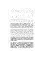
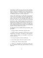
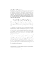
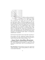
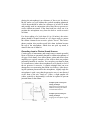
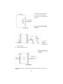
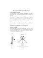
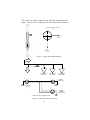
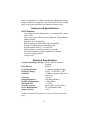
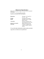
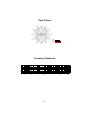
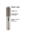
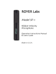
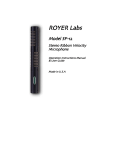
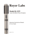
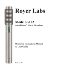
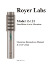
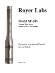
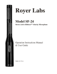
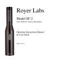
ROYER Labs
Model R-122
Active Ribbon
Velocity Microphone
Operation Instructions
Manual &
Users Guide
Made in U.S.A.
TABLE OF CONTENTS
Model R-122 Ribbon Microphone
Table of Contents
page 1
Introduction
page 2
Description
page 3
Applications
page 4
User Guide
page 5
Operation
page 6
Amplification Considerations
page 8
The Sweet Spot
page 11
Other Types of Microphones
page 13
Proximity Effect and Working Distance
page 13
General Tips
page 14
Stereophonic Microphone Technique
page 18
Specialized Recording Techniques
page 20
Care and Maintenance
page 21
A Little Bit of History
page 22
Features and Specifications
page 24
Electrical Specifications
page 24
Mechanical Specifications
page 25
Polar Pattern and Frequency Response
page 26
Notes
page 27
Warranty
page 28
1
R-122 Active Ribbon Microphone
Congratulations on your purchase of a Royer model R-122 active
ribbon microphone! The R-122 is a handcrafted precision instrument capable of delivering superior sound quality and overall high
performance. The R-122 is the most technologically advanced ribbon microphone available, representing a new level of performance for ribbon microphones. The R-122 active ribbon microphone combines sophisticated technological advancements with
old-world craftsmanship. The R-122 incorporates a head amplification system which operates on standard 48-volt simplex power,
just like a standard condenser microphone. This enables the R-122
to deliver the same sensitivity and output performance that the recording industry has grown accustomed to with modern condenser
microphones. In addition, the active circuitry completely isolates
the ribbon element from impedance mismatches, short-circuits
and other anomalies that can degrade microphone performance or
damage the ribbon. The R-122 breaks the long-standing taboo associated with ribbon microphones and phantom power. It is the
first commercially available ribbon microphone that requires
phantom power to operate.
•
No longer is it necessary to mate a ribbon microphone to
an ultra-high gain, low noise preamplifier for optimum
performance. Any preamplifier of nominal gain will provide good results with the R-122.
•
No longer is it necessary to carefully consider impedance
matching characteristics when choosing a preamplifier.
Microphone loading is a non-issue and consistent performance is assured, regardless of the preamplifier’s impedance
characteristics.
•
No longer is it necessary to be concerned about damaging
the ribbon element with phantom power. The active electronics provide true isolation between the ribbon element
and the outside world.
•
No longer is it necessary to worry about the effects of long
2
cable runs degrading the performance of your ribbon microphone. The active electronics provide a robust low impedance signal suitable for all types of preamplifiers.
This operator’s manual describes the R-122, its function and
method of use. It also describes the care and maintenance required to ensure proper operation and long service life. The User
Guide section of this manual offers practical information that is
designed to maximize the performance capabilities of this microphone.
Royer Labs products are manufactured to the highest industrial
standards using only the finest materials obtainable. Your model
R-122 went though extensive quality control checks before leaving the factory. Normal care, given to any quality instrument, is
all that is required to assure years of trouble-free service.
Please read the manual thoroughly in order to become familiar
with all of the R-122’s capabilities. It will assist you in making
the most of its superior acoustic properties. This owner’s manual
is a handy reference guide and we suggest you refer to it whenever questions arise on the use and care of your R-122 active ribbon microphone.
Description
The Royer Labs model R-122 is a compact, active, bi-directional
(figure-eight) velocity type ribbon microphone designed for professional applications. The figure-eight pickup pattern allows the
R-122 to be addressed from either side with equal sensitivity. The
in-phase signal is achieved when the microphone is addressed
from the front, indicated by the “ROYER” logo.
The R-122 is reasonably tolerant to shock and vibration, and performance is unaffected by changes in temperature or humidity.
However, ribbon microphones are somewhat more sensitive to direct blasts of air, and the R-122 is no exception to this rule. Discretionary use of a windscreen or pop screen, such as the PS-100,
PS-101, WS58 or equivalent is highly recommended for situations
3
like close miking, especially with vocalists or certain types of percussion and wind instruments.
Applications
The Royer Labs model R-122 is a versatile microphone and is ideally suited for many critical recording applications. Its smooth
frequency response characteristics and ability to capture detail
make it a fine choice for many instruments, as well as for general
broadcast applications. Its gentle low-frequency proximity effect
make it especially useful for vocalists and announcers. Female
vocalists often benefit from the R-122’s ability to capture high frequencies without distortion or edginess. Orchestral instruments
are captured in a natural sounding way, free from microphoneinduced “hype”. The R-122 has exceptionally smooth high frequency characteristics and is devoid of microphone induced ringing. Phase-related distortion and irregular frequency peaks are
conspicuously absent. These features make the R-122 ribbon microphone an ideal choice for strings, woodwinds, percussion and
amplified instruments. Theater organs and electric guitar amplifiers sound big and fat, without unnatural coloration, when recorded
with the R-122. Acoustic pianos can be captured accurately without the comb-filtering effects associated with condenser microphones.
Digital recordings benefit greatly from the properties inherent in
ribbon microphones. Since A to D converters cannot distinguish
between the sound source being recorded and the complex distortion components associated with condenser microphones, they
sometimes have difficulty tracking the signal, resulting in ringing
and edgy sounding tracks. With ribbon microphones, ringing is almost non-existent due to the ribbon’s lack of distortion artifacts
and high frequency peaks. A to D converters have less difficulty
tracking the ribbon generated signal, resulting in very smooth digital recordings free of microphone related edginess.
User Guide
Using The R-122 Active Ribbon Microphone
4
The head amplification system utilized in the active series ribbon
microphones is designed to operate with standard 48-volt simplex
phantom power sources only. The microphone will not work at
all if phantom power is not provided to the microphone! This aspect of an active ribbon microphone is in sharp contrast to the
common wisdom normally applied to ribbon microphones, where
phantom power usually spells danger or destruction to the ribbon
element. Active ribbon microphones require phantom power to
operate.
To ensure long service life of your R-122 active ribbon microphone, care should be taken when connecting the microphone to a
phantom power source. We have prepared a few tips to ensure
that your active ribbon microphone will perform perfectly for
many years. We offer the following information as a general set
of “good habits” that apply to both active ribbon mics and solidstate condenser microphones.
1. Always be certain that the correct microphone cable is used
with the microphone, and that the cable is in good serviceable order. Standard microphone cables provide a shielded ground carried along to Pin-1, and a balanced differential signal carried
along Pins-2 & 3. Pin-2 is signal hot (in phase) and Pin-3 is signal
cold.
2. Although it is usually safe to “hot plug” most phantom powered microphones to a preamplifier or console with the phantom
activated, we suggest that if it is possible to de-activate the phantom power prior to plugging the microphone to the cable, do so.
This minimizes any chance of random voltage surges entering the
microphone. More importantly, it reduces the possibility of loud
pops being transmitted to your monitor speakers should the volume control be raised. Serious damage to your speakers could result from this activity.
3. Be certain that the input channel fader or volume control is set
to minimum before plugging in any microphone. Preamplifier
gain trim should be set to minimum. Plug the microphone into the
5
cable and activate the phantom power switch. The microphone’s
electronics will stabilize in a few seconds.
4. When the microphone becomes operational, bring the channel
fader to 0-dB (unity) and use the trim to set desired level. This
technique maximizes the signal-to-noise performance of the preamplifier or console input channel.
5. When disconnecting the microphone, bring the channel fader
down and unplug the microphone from the cable. It is also advisable to deactivate the phantom power switch before unplugging
the microphone whenever possible.
6. If the studio has the microphone lines brought to a patch bay
(tie lines), never crosspatch a microphone line when phantom is
applied or the monitor volume is raised. This could cause damage
to your microphone, preamplifier or monitor speakers.
Operation
The R-122 ribbon microphone is a versatile device capable of accurate sound reproduction. Ribbon microphones are different
from other types of microphones and there are a few important
characteristics that are key to understanding how to use them intelligently.
1. The R-122 is a side address, bi-directional microphone and
the rejection in the “dead” areas is very strong. Due to this directionality, ribbon microphones should be placed at 1.3 times the
distance normally used with omni-directional microphones, or at
about the same distance used for cardioid microphones. This
method is used to achieve the same ratio of direct to reflected
sound.
2 In the horizontal plane, ribbon microphones do not discriminate against the “highs” off axis; nor do they boost them on axis.
Therefore, several instruments or vocalists can be placed in front
of the microphone without favoring the performer positioned in
the center of the group.
6
Several performers can be grouped at both the front and back of
the microphone, with one proviso; since the outputs are out of
phase at the front and back of the microphone, cancellation can
result if, for example, two tenors are placed at opposite sides at
equal distances and they are singing in unison, so listen to the
feed before committing to it.
3. When using a ribbon microphone with loud signal sources,
placing the microphone slightly off axis relative to the signal
source (either horizontally or vertically) is all that is required for
efficient operation. This practice will help to protect the ribbon
from extraneous stretching and possible damage.
4. Never attempt to “test” the R-122 or any ribbon microphone
with an ohmmeter or continuity tester. On an active microphone,
damage to the delicate electronics could occur; on a passive ribbon microphone, a blown ribbon could result.
5. Always provide adequate protection for your R-122, or any
ribbon microphone. If the microphone is to remain set up on a
stand when not in use, place a “mic sock” (supplied with every
Royer microphone) over it until it is to be used. Do not carry the
microphone around without placing a mic sock over it. Failure to
follow this commonsense practice may yield a stretched ribbon
and compromised performance.
6. Do not allow the microphone to be dropped on hard surfaces
such as floors or tables - depending on how the mic falls, you
could stretch the ribbon. In a situation like this the microphone
would likely continue to operate but performance could be compromised considerably. Re-ribboning the microphone would be
necessary to restore normal operation.
Amplification Considerations
Almost any microphone preamplifier, with nominal gain characteristics and a built in 48-volt phantom power source will give ex7
cellent results with your R-122 active ribbon microphone. Unlike
standard ribbon microphones, which depend on a proper impedance match to deliver optimal performance, the input impedance
of your preamplifier will have minimal affect on the R-122’s operational performance because the ribbon element is isolated from
the outside world via the microphone’s electronics package.
Careful consideration should be given to the quality of the microphone preamplifier. Studio grade preamplifiers usually sound
much better than cheap ones. Headroom, noise floor, transparency
and coloration are all factors to consider in determining which
preamplifier is suitable for your studio or live sound application.
Other features are usually secondary and fall into the category of
conveniences or interface capabilities (such as digital or optical
outputs). A good preamplifier should sound natural with no sign
of edginess or excessive noise. Vacuum tube preamplifiers sound
warm, yet wonderfully airy and transparent. Do not expect a vacuum tube preamplifier to be as quiet as a solid-state preamp, as
electron emissions from tubes tend to convey more “thermal”
noise than transistors. Transformer coupled designs tend to sound
punchy and full-bodied and offer the added benefit of true electronic isolation. This greatly enhances their ability to interface
with other equipment with minimal noise or hum. There are many
excellent preamplifiers on the market today. Choose one that fits
your budget and offers good performance, but remember that you
get what you pay for. If you have the opportunity to audition one
or more preamplifiers before you buy one, do so. Microphones
and preamplifiers work together like a team and some are just better matches than others.
The R-122 active ribbon microphone is capable of substantial output signal, especially if used in conjunction with very loud signal
sources such as guitar amplifiers. It is therefore recommended
that the microphone preamplifier have a switchable pad to prevent
the possibility of overloading the preamplifier’s input stage electronics. Some preamplifiers are more thoughtfully designed than
others, and a suitable pad will be provided before the active electronics, not incorporated into a “feedback loop” as some cheaper
8
models do. The latter design could still produce unwanted distortion due to overloading, even if the pad were used. Although this
is rarely an issue, we felt that it was important to cover the subject.
Since we’re on the subject of preamplifiers, we thought you might
find the following information on stereo microphones an insightful addition to the information presented on preamplifiers, performance and selection.
Stereo Microphones and Ground Loops
Some preamplifier designs are prone to developing internal
ground loops when used in conjunction with stereo or multichanneled microphones, such as the Royer model SF-12. Although this phenomenon is uncommon, ground loops can develop
in the preamplifier with any stereo microphone, regardless of the
type (i.e. condenser, dynamic, ribbon). A ground loop manifests
itself as unwanted noise, buzz or hum (usually 60 Hz or 120 Hz).
The condition is brought on when the left and right transducer
elements are plugged into two inputs of a stereo or multi-channel
preamplifier. Stereo microphones usually have a multi conductor
cable that carries the two independent signals and then splits them
to a pair of standard three-pin XLR outputs. This pair of three-pin
connectors usually shares Pin-1 as ground, so they are grounded
to each other through the cable set. If the grounding scheme
within the preamplifier is poorly designed, or the distances to internal ground are too great, a ground loop develops. The problem
may be more apparent with some low output microphones such as
dynamics or passive ribbons because of the high gain required for
efficient operation.
You can perform a simple test to check for this condition
(preferably done with a pair of headphones to avoid feedback).
Plug one side of the stereo microphone into either preamplifier input. Listen to the output of the preamp. All should be quiet except for the mic signal. Now plug the second side into the next
preamplifier input. If a noise or buzz develops, you have a
9
ground loop. The ground loop may be very slight or more pronounced, depending on the preamp. Battery powered preamps
usually do not exhibit this problem, and neither do well designed,
line operated mic preamps. The simple fix is to disconnect one of
the microphone’s two Pin-1 ground connections. A better method
is to make a small ground lifter adapter out of a male-female XLR
barrel adapter. Switchcraft makes a very nice one and it takes
less than five minutes to wire it up. Simply connect Pin-2-to-Pin2, Pin-3 to Pin-3, and leave Pin-1 disconnected. Correcting the
problem at the preamplifier would be preferable, but is often more
difficult and/or expensive.
In conclusion, try to find the best preamp you can afford that has
good gain characteristics and low noise. Coloration is optional
and a matter of personal taste. Some people love the effect of coloration while others strive for absolute transparency.
Equalization and Ribbon Microphones
One of the great strengths of ribbon microphones is how well they
take EQ. Even with substantial amounts of equalization, ribbons
retain their natural, “real” quality. For example, when a lead vocal is being performed on a ribbon microphone, you can actually
boost the upper end frequencies to the point where the ribbon mic
emulates the performance curve of a condenser mic with excellent
results. This is not to say that a ribbon microphone can replace a
quality condenser mic in all circumstances, but the EQ friendliness inherent in ribbon microphones does allow for an enormous
amount of flexibility.
The reason that ribbon mics take EQ so well is because of their
inherent low self-noise (less than 15 dB) and unusually smooth
response characteristics. Dialing in high amounts of equalization
on condenser or dynamic microphones also means dialing in extra
amounts of the microphones distortion products and self noise;
garbage that contributes to an unnatural, unpleasant sound. Because distortion and self-noise are almost non-existent in ribbon
microphones, high levels of EQ can be used without adding
harshness or excessive noise.
10
Hum, Noise and Mic Orientation
All dynamic microphones, including ribbons, utilize powerful
magnets in their motor assemblies and matching transformers,
and are, to some degree, susceptible to picking up stray alternating magnetic fields. Power transformers (such as those found in
guitar amplifiers) and alternating current motors are the most
likely sources of radiated noise. Building wiring and electrical
utility transformers are other likely sources. A well-designed
microphone provides shielding to minimize the effects of stray
magnetic radiation. In some cases complete isolation is impossible and the result is usually hum or buzz. Passive ribbon microphones can potentially manifest this condition to a greater degree
because of their higher gain requirements. Even an active ribbon
microphone like the R-122 is not completely immune to this phenomenon. With vintage ribbon microphones that employ large
bulky magnet structures, the problem can be worse. The cure for
this problem is to identify the source of the noise and move the
microphone away from it. Another trick is to alter the orientation
of the microphone in such a way that the noise is cancelled out. If
you ever experience this situation while in the studio, try rotating
the microphone to identify the “null” point, then reposition the
mic and the sound source.
The Sweet Spot
Finding and Working with the Sweet Spot
Good engineers know the importance and benefits of finding and
working with the “sweet spot” of a given microphone. The sweet
spot is usually defined as the optimum placement (working distance and angular position) of any microphone relative to the
sound source.
Each microphone has its own sweet spot whether it is a ribbon,
dynamic or condenser type. The sweet spot will vary with the
type of sound source and its volume intensity, the polar pattern of
the microphone and how consistent it is with frequency, and the
acoustic environment.
11
This condition is called the sweet spot because the microphone
and the sound source are in a harmony of sorts; the acoustic information is exciting the microphone in such a fashion that the resulting reproduction is very desirable, usually without the need
for additional equalization or electronic manipulation.
There are only general rules as to where the sweet spot may be
found for any given microphone, and usually experimentation reveals it. The sweet spot can be extremely variable since it depends on the quirks of a given microphone and acoustics of a
given room. Once the sweet spot is discovered, this placement
can become a “rule of thumb” starting point for future microphone placement with similar sound sources. Remember this: If it
sounds good, it’s probably right. If it doesn’t, move the microphone. It’s often more effective to reposition the microphone than
to start fiddling with knobs. Knob twisting can affect headroom
and phase coherency and add unwanted noise.
The following is a list of variables that also account for “sweet
spot” effect.
1. Frequency response variations due to proximity effect.
2. Frequency response variation due to treble losses as a result of
absorption and “narrowing” of the pattern at high frequencies,
causing weakening of highs as the microphone is moved away
from the sound source.
3. Rise in treble response on-axis due to diffraction.
4. Loss of treble response off-axis due to phase-loss effect.
5. Variation in ratio of direct/reverberant sound.
6. Tendency of a microphone to favor the nearest sound source
due to a combination of these items, plus the influence of inverse
square law.
12
Other Types of Microphones
For the same ratio of direct/reverberant sound, omni-directional
microphones must be closer to the sound source than cardioid or
bi-directional microphones. Microphones should generally face
the sound source head-on; if not, treble losses due to phase loss
will result. The exception here is for large condenser microphones, which often give the flattest response at an angle of about
10-20 degrees (off axis), where phase loss and diffraction effect
offset each other somewhat.
Proximity Effect and Working Distance
The Sound That Is “More Real than Real”
Ribbon microphones have long been renowned for “rich bass”.
This effect is largely due to the fact that ribbon microphones generally have excellent bass response to begin with, and at the same
time exhibit an effect known as “proximity effect” or “bass tipup”.
As illustrated in the following graph, a typical bi-directional ribbon microphone will have a flat frequency response at a distance
of about six feet from the microphone but at shorter distances the
bass response becomes boosted; the effect becomes increasingly
pronounced as the distance between the microphone and the
sound source is reduced.
This bass-boosting characteristic can become quite intense and, if
desired, can be corrected by equalization. However, for a multiple
microphone setup, the pronounced bass boosting (due to proximity effect) can be turned to an advantage. If an instrument,
such as a trumpet, is extremely close-miked and the bass is cut to
restore flat response, unwanted low-frequency sounds are cut
back by upwards of 20 dB compared to an unequalized microphone with a flat response. This discrimination is independent of
the microphone’s polar response.
Typical relationship of microphone distance to frequency response for ribbonvelocity bi-directional microphone.
13
Another area where proximity effect can be turned to an advantage is to make things sound
more “real than real”. For example, many voices and certain musical instruments produce fundamental frequencies within the
bass range (below 150 Hz or so) but the fundamentals are weak.
If a microphone which has no proximity effect and a rising high
frequency response is used on an upright piano, or on a person
with a thin, weak voice, the recorded sound is likely to sound
even thinner than it was in real life. In contrast, using a microphone with strong proximity effect on such sound sources could
result in a “better than real” sound since the boosted bass response will compensate for the weak fundamentals in the sound
source. Since the fundamentals are present, but weakened, boosting them by several dB will sound “natural”, even though the
sound has been “sweetened”.
Radio and television announcers have long relied on proximity effect to produce a full, rich, “authoritative” quality to their voices.
By knowing how to work with the proximity effect, the engineer
can get several useful effects without resorting to a “box”.
General Tips for Using Ribbon Microphones
Brass Instruments and ribbon microphones go together very
well. Mic the instrument from a distance of a couple of feet, and
increase the working distance a little if several instruments are being used.
Reed Instruments sound full and never edgy when captured with
a ribbon microphone. Normal working distances are about a foot
or two from the instrument.
14
Strings sound very sweet and clean with ribbon microphones.
Place the microphone several feet from the instrument. For larger
string sections, placing the microphone slightly above the instrumentalists and angled down; a distance of three or four feet will
do the trick nicely.
Pianos sound excellent with ribbon microphones and are free of
phase-related comb filtering. The bass is full and rich while the
top remains clean with no clatter. Mic the piano at a distance of
one foot to several feet, depending on taste. A more direct “up
front” sound will be achieved when the microphone is placed
closer to the soundboard.
For capturing a piano in stereo, place the microphones apart, one
over the bass strings and the other over the high strings. The farther the mics are from each other, the wider the stereo spread. For
a more direct stereo effect, the microphones may be placed in an
“X” pattern a couple of feet from the center of the soundboard.
Amplified Instruments should be miked from a distance of one
foot or more. The smooth undistorted response of a ribbon microphone is very useful for electric guitars and electric bass.
Since guitar amplifier speakers are often “beamy”, experiment
with mic placement to find just the right spot. Placing the mic at
greater distances from the speaker cabinet adds more room ambience to the mix. You will find that a ribbon microphone does not
add any undesirable elements to the sound. Basically, what you
hear at the amp is what you get in the control room.
Choirs and Orchestras can be picked up well with two microphones. Place the microphones at a distance of ten feet above the
floor, and a few feet behind the conductor. The microphones
should be spaced apart approximately one foot and angled, one
toward the left and one toward the right.
Drums and Percussion instruments sound natural when microphones are placed at a distance of several feet. For a drum set,
15
placing the microphone(s) at a distance of four to six feet above
the kit works very well without the cymbals sounding splattered.
A kick drum should be miked at a distance of at least 18 inches
and possibly used in conjunction with a blast filter to prevent excessive ribbon movement. If the front head has a hole cut it in,
position the microphone away from the hole to avoid excessive
air blasts.
For closer miking of a kick drum (10 to 18 inches), the microphone should be leaned forward at a 45 degree angle to protect
the ribbon element from excessive plosive forces. This microphone position also provides good kick drum isolation because
the top of the microphone, which does not pick up sound, is
aimed at the rest of drum kit.
Recording Loud or Plosive Sound Sources
Certain types of instruments and sound sources contain powerful
blasts of air that are potentially harmful to ribbon microphones of
all types. Kick drums, close miked horns, guitar and electric bass
amplifiers are typical examples of the sources that can produce
potentially harmful air currents. You can place your hand in front
of a sound source (where the microphone is to be placed) to feel if
the air pressure is excessive. A simple technique that can avert
damage due to overstressing the ribbon is as follows: After choosing the optimum placement for the microphone, slightly angle the
microphone is such a way that the percussive wave is not directed
at the front of the mic “head on”. Often, a slight angular tilt
(either vertically or horizontally) is all that is required to prevent
potential harm to the ribbon.
Example of the vertical positioning technique
Slight off-axis positioning will
minimize stressing the ribbon
on loud sound sources.
Example of horizontal positioning technique
Angling the microphone slightly
16
will minimize stressing the ribbon. Due to the microphone’s
pickup pattern, sound will not be
affected.
Side view of kick drum miking
technique
A) Close
miking—
angle mic so
that pressure
wave is off-axis
B) Standard miking position
Horizontal positioning
technique
Applied to kick drum— similar to that utilized for other loud or percussive instruments
17
Stereophonic Microphone Technique
Classic Blumlein Technique
For many years, several “coincident” microphone setups have
been widely used for picking up sounds in stereo as naturally as
possible.
The “Blumlein” technique, named for A.D. Blumlein of England,
involves the use of two figure-eight microphones positioned as in
the sketch (see Figure 1), so that one faces left and the other right,
at an angle of 90º (i.e. each displaced 45º from center).
Each microphone ultimately feeds one speaker in a stereo system,
and due to the directionality of the microphones, the result is a
very well defined stereo effect on playback. For classical music,
particularly, the reproduction can be very satisfying.
Mid-Side Technique
In the early days of stereo radio broadcasting, there was a need
for a mic setup that would allow for simultaneous stereo and
mono feeds from the same mic array and for electronic “fiddling”
with the severity of the stereo effect.
Coincident pair as seen from
directly above
45 Degrees
45 Degrees
Sound Source
(CENTER)
Figure 1
Classic Blumlein or “coincident” miking
technique
18
The result was what is known as the mid-side microphone technique. One mic faces sideways, one faces forward as shown in
Mid-Side pair as seen from directly
above
S
90 Degrees
M
Sound Source
(Center)
Figure 2 - Typical M-S miking technique
SIDE
NOTE:
INVERT PHASE
0
MID
Mixer Channel
Pan LEFT
1
Mixer Channel
Pan RIGHT
2
2
3
1
Mixer Channel
Pan CENTER
XLR Male
Right Output
3
XLR Female
(to mic)
2
1
XLR Male
Left Output
(phase reversed)
3
“Y” adapter mic splitter with phase reversal
Figure 3 - Typical M-S connection set-up
19
Figure 2, and they are connected as shown in Figure 3.
When the outputs of the pair of microphones are combined at the
mixer, they will behave like a pair of microphones, one facing
left and one right, provided that the sensitivities of the mics are
equal and the mixer channel gains are equal.
Turning down the side mic all the way will give a mono pickup;
as the side mic is turned up, the stereo effect will gradually appear.
If the outputs of the “mid” and “side” microphones are recorded
on separate tracks, the electrical connections shown in Figure 3
could be made at the mixer outputs and the adjustment of the stereo separation could be done during mixdown, rather than during
the actual recording - very useful for live recording.
Specialized Recording Techniques
Recording on the back side of the R-122
The R-122 incorporates an “offset ribbon” design that enables it
to handle high sound pressure levels such as those produced by
loud guitar amplifiers and other instruments. An interesting phenomenon as a result of this “offset ribbon” construction occurs at
the microphone’s backside, which affects the high frequency and
low frequency response characteristics within the microphone’s
proximity range. This proximity range is loosely defined as
sound sources that are three feet or closer to the microphone.
Normal proximity effect (increase of bass), which is prevalent on
the R-122 and all ribbon microphones, occurs normally at 4-6 feet
from a ribbon microphone and increases with closeness. Vocalists
and voice-over talents often take advantage of proximity effect to
give an authoritative quality or rich texture to their voice.
Due to the R-122’s unique offset ribbon design, the backside of
the R-122 records somewhat brighter than the front (logo) side,
when the microphone is three feet or closer to the sound source.
This can be extremely useful for recording acoustic instruments
and vocalists where a little less warmth may be desirable. When
20
recording vocals on either side of an R-122, a quality pop filter
(such as the Royer PS-100 or PS-101 metal pop screen) is essential to protect the ribbon element from windblasts. As with any
figure-8 microphone, the front side of the R-122 is in-phase and
the backside is out-of-phase. We suggest that that you reverse the
phase polarity on your microphone preamplifier to achieve inphase recordings when tracking on the backside of an R-122.
Cautionary Note:
It is important to note that the SPL handling capability of the
rear side of the R-122 is less than its front side. When tracking
loud sounds on the front side, the R-122's offset-ribbon design allows ample space for rearward excursions of the ribbon. However, tracking on the back side causes the ribbon to move forward
towards the front side of the microphone, where the dampening
screen is much closer to the ribbon element. Rear side recordings
of loud sounds, or vocalists with no pop filter, can drive the ribbon into the front dampening screen, creating noise and possibly
damaging the ribbon element. Limit backside recording on your
R-122 to lower SPL sound sources and the microphone will be
fine.
Care and Maintenance
The R-122 is a well-built precision instrument. All that is required to ensure proper operation of this microphone is to follow
some commonsense rules.
1. Avoid transducer damage by not exposing the microphone to
severe shock or vibration. If the microphone is accidentally
dropped, test it to see if damage has occurred before returning it
to service.
2. Do not expose the microphone to direct blasts of air. Use a
windscreen or suitable blast filter when close miking a vocalist or
certain types of wind instruments. P-popping does not necessarily damage the ribbon element but may produce unacceptable preamplifier overload and could cause damage to speaker systems.
21
3. Do not expose the microphone to liquids or caustic smoke.
4. Do not expose the microphone to strong alternating electromagnetic fields, i.e. the power transformers in amps, or a hum
may result.
5. Use a soft cloth to clean the microphone body. A small
amount of denatured alcohol can be used to remove fingerprints
and other stains.
6. Keep metal filings away from the microphone at all times.
7. When not in use, store the microphone in its protective
wooden case.
8. Leave disassembly of the microphone to a trained technician.
There are no user-serviceable parts inside.
Caution!
Keep recorded tapes, spring-wound watches, and personal credit
cards using magnetic coding away from the microphone to prevent possible damage caused by the transducer’s powerful magnets.
A Little Bit of History
The ribbon-velocity microphone design first gained popularity in
the early 1930s and remained the industry standard for many
years. Their characteristic sound signature can still be appreciated
today in recordings of the 30s, 40s, 50s and early 60s.
Ribbon microphone development reached its pinnacle during this
time. Though they were popular with announcers, one of the disadvantages of ribbon microphones was their immense size. Even
though these devices were considered state-of-the-art, magnetic
structures of the time were bulky and inefficient. Transformers
suffered a similar deficiency. When television gained popularity
in the late 1940s, it was obvious that their size was intrusive and
objectionable. They were difficult to maneuver and broadcasters
soon looked for a suitable replacement. Even though these micro22
phones performed very well, their days were numbered. Newer
dynamic and condenser mics would soon replace them. The new
designs were compact, rugged and sensitive. It wasn’t long before the television industry embraced these new designs. Radio
followed the trend shortly afterward. Further technological development of ribbon microphones was considered unnecessary and
the beloved ribbon soon faded into obscurity. It is a fate reminiscent of that of the vacuum tube when transistors hit the scene less
than a decade later.
Some of their unique characteristics, unmatched even by today’s
modern condensers and dynamics, are still revered by many professionals, as evidenced by the high prices that vintage ribbons
command in the marketplace.
Traditional-style ribbon microphones are still being manufactured
in limited quantities today by a few dedicated companies. These
microphones are essentially similar to the designs of the 1930s
and limited to specialized applications.
Recent developments in magnetics, electronics and mechanical
construction procedures have made it possible to once again bring
the ribbon microphone to the forefront of the audio field. This is
similar to the resurgence vacuum tubes have made in recent years
now that technology has enabled further development of the state
of the art in numerous areas. A renewed interest in these designs
(both tube technology and ribbon microphones) is driven by the
unique characteristics these devices possess, which remain unmatched even by some of today’s marvels.
Today’s ribbon microphones can be produced smaller and with
sensitivity levels matching those of modern dynamic and condenser microphones. Aside from the superlative audio qualities of
modern ribbon microphones, their smooth frequency response
and phase linearity make them ideally suited for the new digital
formats that dominate recording today. Now, with the introduction of the world’s first active ribbon microphone, the R-122 adds
a whole new chapter to the story of microphones, bringing a new
23
level of performance to ribbons and greatly enhancing the desirability of ribbon microphones across the board. We like to think
that it’s like going from black and white television to color.
Features and Specifications
R-122 Features:
· Very high overload characteristics – maximum SPL greater
than 135 dB
· Active electronics offered greatly enhanced output and true
ribbon isolation.
· Extremely low residual noise
· Ribbon element is unaffected by heat or humidity
· Absence of high frequency phase distortion
· Excellent phase linearity – even off axis
· Equal sensitivity from front or back of element
· Consistent frequency response regardless of distance
· No power supply required
· Compact size
Electrical Specifications
Acoustic Operating Principle
Polar Pattern
Generating Element
Frequency Range
Sensitivity
Self Noise
Output Impedance
Rated Load Impedance
Maximum SPL
Output Connector
Power Requirements
Supply Current
Electro-dynamic pressure
gradient
Figure-8
2.5 micron aluminum ribbon
30 HZ – 15,000 HZ ± 3 dB
-39 dBv (or greater) referenced
Ref 1 v/pa
<20 dB
200 Ohms balanced
> 1000 Ohms
> 135 dB
Male XLR 3 pin (Pin 2 Hot)
48-Volt Phantom Only
4 mA
All Royer monaural microphones are also available in matched
pairs.
24
Mechanical Specifications
High grade Neodymium magnet assembly in Royer’s patented
Flux-Frame
1.5” x 3/16” x 2.5 micron ribbon assembly
Stainless steel internal baffle and dampener
Dimensions
206 mm L x 25 mm W (81/8” L x 1” W)
309 grams (10.9 ounces)
Dull Satin Nickel or Matte
Black Chrome
Protective wood case, mic
clip, and protective mic sock
Shock mount, pop screen
Lifetime to original owner
(repair or replace at Royer’s
option)
Weight
Finish
Accessories
Optional Accessories
Warranty
For up to the minute information on Royer products and their
usage visit our website at www.royerlabs.com
25
Polar Pattern
200 Hz
1000 Hz
10 KHz
Frequency Response
+10
+5
0
-5
-10
20
50
100
500
1000
26
5K
10K
20K
Notes:
27
WARRANTY
Royer Labs warrants its products to be free from defects in materials or imperfect workmanship. This warranty is offered to the
original owner without time limit. Royer Labs will repair or replace any product that fails to meet published specifications during the warranty period. This warranty does not apply if the product has been damaged by accident or misuse, or as a result of repair or modification by other than a Royer Labs customer service
facility authorized to service this product. To validate this warranty, the registration card and a photocopy of the sales receipt
from an authorized Royer Labs dealer must be on file with the
Royer Labs. Should it ever become necessary to service your
Royer Labs product, please contact the factory. In our continuing
effort to improve our products, Royer Labs reserves the right to
make improvements without notice or obligation. Specifications
and prices are subject to change without notice or obligation.
Serial Number__________________
Sensitivity _______________
Resonance________________
Date of Purchase ________________
ROYER Labs
821 North Ford Street
Burbank, California 91505
Telephone 818.760.8472
Fax 818.760.8864
www.royerlabs.com
28