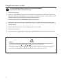
1
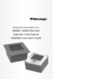
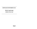
METROLOGIC INSTRUMENTS, INC.
TECH 10 ® LASER BAR CODE
PROJECTION SCANNER (1070)
I NSTALLATION AND USER ’S G UIDE
November 2004
Printed in USA
00 - 02166A
LOCATIONS
CORPORATE HEADQUARTERS
North America
Metrologic Instruments, Inc.
90 Coles Road
Blackwood, NJ 08012-4683
Customer Service: 1-800-ID-METRO
Tel: 856-228-8100
Fax: 856-228-6673
Email: [email protected]
Internet: www.metrologic.com
Metrologic Instruments GmbH
Dornierstrasse 2
82178 Puchheim b.
Munich, Germany
Tel: +49 89 89019 0
Fax: +49 89 89019 200
Email: [email protected]
Germany Email: [email protected]
Spain
Metrologic Eria lbérica SL
Julián Camarillo 29, D-1
Edificio Diapasón
28037 Madrid
Tel: +34 913 272 400
Fax: +34 913 273 829
Email: [email protected]
Italy
Metrologic Instruments Italia srl
Via Emilia 70
40064 Ozzano dell’Emilia (BO)
Tel: +39 0 51 6511978
Fax: +39 0 51 6521337
Email: [email protected]
France
Metrologic Eria France SA
69 Rue de la Belle Etoile
ZI Paris Nord II, BP 50057
95947 – ROISSY CDG CEDEX
Tel: +33 (0) 1 48.63.78.78
Fax: +33 (0) 1 48.63.24.94
Email: [email protected]
EUROPEAN HEADQUARTERS
Germany,
Middle East and Africa
United Kingdom Metrologic Instruments UK Limited
58 Tempus Business Centre
Kingsclere Road, Basingstoke
Hampshire RG21 6XG
Tel: +44 (0) 1256 365900
Fax: +44 (0) 1256 365955
Email: [email protected]
Singapore
Metrologic Asia (Pte) Ltd
No. 8 Kaki Bukit Place
th
4 Floor
Singapore 416186
Tel: 65-842-7155
Fax: 65-842-7166
Email: [email protected]
China
Metro (Suzhou) Technologies Co., Ltd.
221 Xing Hai Street
Suzhou Industrial Park
Suzhou, China
215021
Tel: 86-512-2572511
Fax: 86-512-2571517
Email: [email protected]
Japan
Metrologic Japan Co., Ltd.
Matsunoya Building, 6 Floor
3-14-8 Higashiueno
Taitou-Ku, Tokyo 110-0015 Japan
Tel: 81-3-3839-8511
Fax: 81-3-3839-8519
Email: [email protected]
Brazil
Metrologic do Brasil Ltda.
Rua da Paz 2059
CEP 04713-002
Chácara Santo Antônio
São Paulo, SP, Brasil
Tel: 55-11-5182-8226
Fax: 55-11-5182-8315
Email: [email protected]
Outside Brazil
Metrologic South America
Rua da Paz 2059
CEP 04713-002
Chácara Santo Antônio
São Paulo, SP, Brasil
Tel: 5511-5182-7273
Fax: 5511-5182-7198
Email: [email protected]
ASIA
SOUTH AMERICA
Copyright
© 1999 by Metrologic Instruments, Inc. All rights reserved. No part of this work may be reproduced, transmitted, or stored in any form or by any means without prior written consent, except
by reviewer, who may quote brief passages in a review, or provided for in the Copyright Act of 1976.
Products and brand names mentioned in this document are trademarks of their respective companies.
ii
TABLE OF CONTENTS
Introduction ................................................................................................................................................................ 1
Scanner and Accessories .......................................................................................................................................... 1
Scanner Connections to the Host .............................................................................................................................. 2
Configuration of the Scanner to the Host System...................................................................................................... 3
Parts of the Scanner .................................................................................................................................................. 4
Installation of the Stand ......................................................................................................................................... 5, 6
Labels ........................................................................................................................................................................ 7
Scanning Bar Codes ................................................................................................................................................. 7
Maintenance .............................................................................................................................................................. 8
Appendix A
Specifications......................................................................................................................................... 9, 10
Appendix B
Pin Assignments for the Mil spec Connector .............................................................................................. 11
Appendix C
Limited Warranty......................................................................................................................................... 12
Appendix D
Notices .................................................................................................................................................. 13, 14
Appendix E
Patents........................................................................................................................................................ 15
Index .................................................................................................................................................................. 16, 17
iii
INTRODUCTION
Metrologic's TECH 10® laser bar code projection scanner is encased in a NEMA-12 steel case. The scanner's
construction enables the scanner to operate in harsh surroundings, especially industrial environments. Waterresistant, shock-resistant, and rugged, the TECH 10 scanner is also fast, aggressive and reliable. It can register
bar codes at a range of 203 mm – 559 mm (8" - 22") and can autodiscriminate among all common codes.
Among the scanner’s many features is an Application Specific Integrated Circuit (ASIC) in the decoding system
that virtually eliminates misreads; and MECCA© (Metrologic Enhanced Code Correcting Algorithm), which enables
the scanner to read poorly printed, wrinkled or even torn bar codes on the first pass.
SCANNER AND ACCESSORIES
The following will be contained in the shipping carton:
•
Installation and User’s Guide [MLPN 00-02186]
•
ScanSelect™ Scanner Programming Guide [MLPN 00-02186]
•
TECH 10 Laser Bar Code Projection Scanner
Optional Scanner Accessories
•
Communication Cable with Power Supply
or
Communication Cable
•
Stand [MLPN 45-45479]
To order additional items, contact the dealer, distributor or call Metrologic’s Customer Service Department.
at 1-800-ID-METRO.
1
SCANNER CONNECTIONS TO THE HOST
To avoid potential problems, do not power up the scanner until the
communication cable is secured to the host
1. Turn off the host system.
2. Locate the 19-pin female end of the scanner link cable and find the widest key located above pins L and A.
Align this key with the corresponding key on the scanner box’s Mil spec connector. While pushing in on the
connector, rotate the ring clockwise until it locks into place with a click.
3. Connect the other end of the communication cable to the host device.
4. If the scanner will receive power from an external power source, check the AC input requirements of the
transformer to make sure the voltage matches the AC outlet. The outlet should be near the equipment and
easily accessible.
5. Plug the transformer into the AC outlet to supply the power to the scanner.
6. Power up the host system.
7.
Scan a few items to verify that data is being properly transmitted between the scanner and the host device.
Caution:
To maintain compliance with applicable standards, all circuits connected to the scanner must meet
the requirements for SELV (Safety Extra Low Voltage) according to EN 60950.
To maintain compliance with standard CSA C22.2 No. 950/UL 1950 and norm EN 60950, the power
source should meet applicable performance requirements for a limited power source.
2
CONFIGURATION OF THE SCANNER TO THE HOST SYSTEM
The scanner is shipped from the factory programmed to a set of default conditions noted in the ScanSelect®
Scanner Programming Guide by an asterisk that appears before the brief definition next to the bar code.
In order for the scanner to communicate with the host system properly, it needs to be programmed to meet your
specific scanning needs. Since each host system is unique, the scanner must be configured to match the host
system requirements. The scanner can be configured by entering program mode and scanning the appropriate
bar codes that appear in the ScanSelect® Scanner Programming Guide. (When using ScanSet®, refer to the
ScanSet documentation for information on how to configure the scanner.)
1. Connect the scanner to the host system
(Refer to the Scanner Connections to the Host section in this guide).
2. Enter program mode by scanning the ENTER/EXIT program mode bar code.
(The unit will beep three times)
3. Scan the appropriate bar code(s) that appear in the ScanSelect Scanner Programming Guide.
(Reveal only one bar code to the scanner each time. With your hand, cover the bar code that should not
be scanned.)
4. Exit program mode by scanning the ENTER/EXIT program mode bar code again.
(The new options will be saved and the scanner is ready for normal operation.)
Caution:
To maintain compliance with applicable standards, all circuits connected to the scanner must meet
the requirements for SELV (Safety Extra Low Voltage) according to EN 60950.
To maintain compliance with standard CSA C22.2 No. 950/UL 1950 and norm EN 60950, the power
source should meet applicable performance requirements for a limited power source.
3
PARTS OF THE SCANNER
Becoming familiar with the features of the TECH 10® scanner will help when operating the scanner. The following
illustration and list explain the pertinent parts.
Figure 1
1. Green and Red LEDs
When the green LED is on, this shows that the unit is receiving power and the
laser is on. When the red LED flashes on, the scanner has read a bar code
successfully. When the red light turns off, communication to the host is complete.
2. Laser Output Window
Laser light is emitted from this aperture.
3. Mil spec Connector
This is a 19-pin male Mil spec connector. It is used to connect the scanner to a
host device by using a communication cable with a female Mil spec connector.
The communication cable may include a power transformer or it may be designed
to draw power directly from the host device. The standard TECH 10 only contains
one connector. If the scanner is being used with the MX001 box, then there will
be two Mil spec connectors on the unit.
4
INSTALLATION OF THE STAND
With the Metrologic stand (Part #45-45479), the scanner can be positioned in a vertical orientation. To use this
stand, four 6-32 x ½" machine screws and two #10 panhead wood screws will need to be purchased. The
maximum distance the screws should go into the scanner is ½ inch.
1. Lay the scanner face down on a clean cloth to prevent any scratches from occurring on the output
window. Position the scanner so the red and green LEDs are pointed toward you.
2. Lay the stand on top of the scanner with the angled bracket pointing up and toward you.
3. Align the four clearance holes to the four holes in the scanner’s case. Fasten the stand to the scanner
by inserting the four 6-32 x ½" screws into the four holes in the scanner’s case.
4. Drill two holes into the work surface that correspond with the holes in the 254 mm x 95 mm (10" x 3.75")
base of the stand.
5. Use the two #10 panhead wood screws to attach the stand and scanner to the work surface.
(Refer to Figure 1)
Figure 2
5
Figure 2
6
LABELS
A label is inside the window of the scanner noting that this device is a CDRH Class IIA laser product and IEC 825
LASERKLASSE 1. Also, on the scanner is a label on the back of the unit. This label contains information such as
the model number, date of manufacture, and serial number. The following are samples of the labels that are found
on the unit.
Scanning bar codes
The depth of field for the scanner is 254 mm to 559 mm (10" to 22") from the scanner window. Pass the
symbol through the scan area in order for the scanner to recognize the bar code.
Figure 3
7
MAINTENANCE
Smudges or dirt that appears on the scanner window can interfere with proper scanning. Therefore, only
maintenance required is an occasional cleaning of the glass window.
1. Spray glass cleaner onto lint free, non-abrasive cleaning cloth.
2. Gently wipe the scanner window.
8
APPENDIX A
Specifications
Application:
Light Source:
Laser Class:
Certifications:
EMC:
Universal Industrial Scanner
Visible Laser Diode 650 ± 5nm
CDRH: CLASS IIa; EN 60825 Class 1
CE, UL listed for US and Canada
FCC, ICES-003 & EN 55022 Class A
Mechanical
Dimensions:
Weight:
Orientation:
Mounting:
Top Cover:
311 mm x 262 mm x 108 mm
(12.25" L x 10.32" W x 4.25" D)
5.19 kg. (11.45 lbs.) without cable
May be used in any orientation
Back plate mount or vertical stand
NEMA-12 steel case
Electrical
Power Consumption:
Input Voltage:
Operating Current:
Standby Current:
DC Transformers†:
9 watts, host system or tabletop transformer
11-30 VDC
450 mA typical @ 20V
210 mA typical @ 20V
220V (AC in) 120V (AC in) 230V (AC in)
† All transformers have required agency approvals and have earth ground tied to the core, through to the output.
Specifications subject to change without notice.
9
APPENDIX A (CONTINUED)
Operational
Depth of Scan Field:
Scan Speed:
Scan Pattern:
Exit Angle:
Indicators:
Beeper Operation:
Maintenance Required:
Decode Capability:
System Interfaces:
Print Contrast:
Roll, Pitch, Yaw:
254 mm to 559 mm (10" to 22")
1,250 scan lines per second
25 line omnidirectional
12° down off perpendicular of scan window
LED: red = good read; green = laser on
Selection of 3 tones for “Good Read”
Clean window periodically
Autodiscriminates
RS232C; Light Pen Emulation; OCIA; RS422
35% minimum reflectance difference
360°, 60°, 60°
Environmental
Storage Temperature:
Operating Temperature:
Humidity:
Light Levels:
Ventilation:
Shock:
ESD:
Contaminants:
-40°C to 60°C (-40°F to 140°F)
0°C to 35°C (32°F to 95°F)
5% to 95% relative humidity, non-condensing
Up to 3200 foot candles - works in direct sun
None required
100 g for 1 ms
8 kV IEC 801-2
Protects against dust, falling dirt, and dripping non-corrosive liquid
Specifications subject to change without notice.
10
APPENDIX B
Pin Assignments for the Mil spec Connector
Each TECH 10®scanner has a 19-pin male Mil spec connector that is on the side of the unit. To connect the
scanner to the host device, use a communication cable with a female Mil spec connector. The communication
cable may include a power transformer or it may be designed to draw power directly from the host device. This
item can be ordered when the scanner is purchased.
The following is a list of the pin assignments. The pin numbers are impressed on the male Mil spec connector The
Tech 10® scanners are manufactured by Metrologic at its Blackwood, New Jersey, U.S.A. facility. For easier
reference, refer to Figure 5 for pin locations.
PIN
FUNCTION
A
B
C
D
E
F
G
H
R Data
RTS Output
Signal Ground
CTS Input
R Data Return
RS-232 Output
Clock in
Clock In Return
J
K
L
M
N
Clock Out
Shield Ground
DTR Input
Clock Out Return
Power to Scanner & 24 VDC
P
Earth Ground
R
S
Power Ground
RS-232 Input
Figure 5
11
APPENDIX C
Limited Warranty
The Tech 10® scanners are manufactured by Metrologic at its Blackwood, New Jersey, U.S.A. facility Tech 10®.
The Tech 10® scanners have a two (2) year limited warranty from the date of manufacture. Metrologic warrants
and represents that all Tech 10® scanners are free of all defects in material, workmanship and design, and have
been produced and labeled in compliance with all applicable U.S. Federal, state and local laws, regulations and
ordinances pertaining to their production and labeling.
This warranty is limited to repair, replacement of Product or refund of Product price at the sole discretion of
Metrologic. Faulty equipment must be returned to the Metrologic facility in Blackwood, New Jersey, U.S.A. or
Puchheim, Germany. To do this, contact Metrologic’s Customer Service/Repair Department to obtain a Returned
Material Authorization (RMA) number.
In the event that it is determined the equipment failure is covered under this warranty, Metrologic shall, at its
sole option, repair the Product or replace the Product with a functionally equivalent unit and return such
repaired or replaced Product without charge for service or return freight, whether distributor, dealer/reseller,
or retail consumer, or refund an amount equal to the original purchase price.
This limited warranty does not extend to any Product which, in the sole judgement of Metrologic, has been
subjected to abuse, misuse, neglect, improper installation, or accident, nor any damage due to use or
misuse produced from integration of the Product into any mechanical, electrical or computer system. The
warranty is void if the case of Product is opened by anyone other than Metrologic’s repair department or
authorized repair centers.
THIS LIMITED WARRANTY, EXCEPT AS TO TITLE, IS IN LIEU OF ALL OTHER WARRANTIES OR
GUARANTEES, EITHER EXPRESS OR IMPLIED, AND SPECIFICALLY EXCLUDES, WITHOUT
LIMITATION, WARRANTIES OF MERCHANTABILITY AND FITNESS FOR A PARTICULAR PURPOSE
UNDER THE UNIFORM COMMERCIAL CODE, OR ARISING OUT OF CUSTOM OR CONDUCT. THE
RIGHTS AND REMEDIES PROVIDED HEREIN ARE EXCLUSIVE AND IN LIEU OF ANY OTHER RIGHTS
OR REMEDIES. IN NO EVENT SHALL METROLOGIC BE LIABLE FOR ANY INDIRECT OR
CONSEQUENTIAL DAMAGES, INCIDENTAL DAMAGES, DAMAGES TO PERSON OR PROPERTY, OR
EFFECT ON BUSINESS OR PROPERTY, OR OTHER DAMAGES OR EXPENSES DUE DIRECTLY OR
INDIRECTLY TO THE PRODUCT, EXCEPT AS STATED IN THIS WARRANTY. IN NO EVENT SHALL
ANY LIABILITY OF METROLOGIC EXCEED THE ACTUAL AMOUNT PAID TO METROLOGIC FOR THE
PRODUCT. METROLOGIC RESERVES THE RIGHT TO MAKE ANY CHANGES TO THE PRODUCT
DESCRIBED HEREIN.
USA Corporate Headquarters
Metrologic Instruments, Inc.
90 Coles Road
Blackwood, NJ 08012-4683
Customer Service: 1-800-ID-METRO
Tel: 856-228-8100
Email: [email protected]
www.metrologic.com
12
Germany
Metrologic Instruments Gmbh
Dornierstrasse 2
82178 Puchheim b.
Munich, Germany
Tel: 49-89-89019-0
Fax: 49-89-89019-200
Email: [email protected]
APPENDIX D
Notice
This equipment has been tested and found to comply with limits for a Class A digital device, pursuant to part 15 of the FCC
Rules. These limits are designed to provide reasonable protection against harmful interference when the equipment is operated
in a commercial environment. This equipment generates, uses and can radiate radio frequency energy and, if not installed and
used in accordance with the instruction manual, may cause harmful interference to radio communications. Operation of this
equipment in a residential area is likely to cause harmful interference, in which case the user will be required to correct the
interference at his own expense. Any unauthorized changes or modifications to this equipment could void the users authority to
operate this device.
This device complies with part 15 of the FCC Rules. Operation is subject to the following two conditions: (1) This device may not
cause harmful interference, and (2) this device must accept any interference received, including interference that may cause
undesired operation.
Notice
This Class A digital apparatus complies with Canadian ICES-003.
Remarque
Cet appareil numérique de la classe A, conformé a la norme NMB-003 du Canada.
Caution
Use of controls or adjustments or performance of procedures other than those specified herein may result in hazardous laser
light exposure. Under no circumstances should the customer attempt to service the laser scanner. Never attempt to look at the
laser beam, even if the scanner appears to be nonfunctional. Never open the scanner in an attempt to look into the device.
Doing so could result in hazardous laser light exposure. The use of optical instruments with the laser equipment will increase
eye hazard.
Atención
La modificación de los procedimientos, o la utilización de controles o ajustes distintos de los especificados aquí, pueden
provocar una luz de láser peligrosa. Bajo ninguna circunstancia el usuario deberá realizar el mantenimiento del láser del
escáner. Ni intentar mirar al haz del láser incluso cuando este no esté operativo. Tampoco deberá abrir el escáner para
examinar el aparato. El hacerlo puede conllevar una exposición peligrosa a la luz de láser. El uso de instrumentos ópticos con
el equipo láser puede incrementar el riesgo para la vista.
Attention
L'emploi de commandes, réglages ou procédés autres que ceux décrits ici peut entraîner de graves irradiations. Le client ne
doit en aucun cas essayer d'entretenir lui-même le scanner ou le laser. Ne regardez jamais directement le rayon laser, même
si vous croyez que le scanner est inactif. N'ouvrez jamais le scanner pour regarder dans l'appareil. Ce faisant, vous vous
exposez à une rayonnement laser qú êst hazardous. L'emploi d'appareils optiques avec cet équipement laser augmente le
risque d'endommagement de la vision.
Achtung
Die Verwendung anderer als der hier beschriebenen Steuerungen, Einstellungen oder Verfahren kann eine gefährliche
Laserstrahlung hervorrufen. Der Kunde sollte unter keinen Umständen versuchen, den Laser-Scanner selbst zu warten. Sehen
Sie niemals in den Laserstrahl, selbst wenn Sie glauben, daß der Scanner nicht aktiv ist. Öffnen Sie niemals den Scanner, um
in das Gerät hineinzusehen. Wenn Sie dies tun, können Sie sich einer gefährlichen Laserstrahlung aussetzen. Der Einsatz
optischer Geräte mit dieser Laserausrüstung erhöht das Risiko einer Sehschädigung.
Attenzione
L’utilizzo di sistemi di controllo, di regolazioni o di procedimenti diversi da quelli descritti nel presente Manuale può provocare
delle esposizioni a raggi laser rischiose. Il cliente non deve assolutamente tentare di riparare egli stesso lo scanner laser. Non
guardate mai il raggio laser, anche se credete che lo scanner non sia attivo. Non aprite mai lo scanner per guardare dentro
l’apparecchio. Facendolo potete esporVi ad una esposizione laser rischiosa. L’uso di apparecchi ottici, equipaggiati con raggi
laser, aumenta il rischio di danni alla vista.
13
APPENDIX D (CONTINUED)
EUROPEAN STANDARD
Warning
This is a class A product. In a domestic environment this product may cause radio interference in which case
the user may be required to take adequate measures.
Funkstöreigenschaften nach EN 55022:1998
Warnung!
Dies ist eine Einrichtung der Klasse A. Diese Einrichtung kann im Wohnbereich Funkstörungen verursachen;
in diesem fall kann vom Betrieber verlangt werden, angemessene Maßnahmen durchführen.
Standard Europeo
Attenzione
Questo e’ un prodotto di classe A. Se usato in vicinanza di residenze private potrebbe causare interferenze
radio che potrebbero richiedere all’utilizzatore opportune misure.
Attention
Ce produit est de classe “A”. Dans un environnement domestique, ce produit peut être la cause d’interférences
radio. Dans ce cas l’utiliseteur peut être amené à predre les mesures adéquates.
14
Appendix E
Patents
For patent information, please refer to www.honeywellaidc.com/patents.
15
Index
Germany (GmbH)
Good read
10
Green LED
4, 5
A
AC
2, 9
Application 9
Asia
ii
ASIC 1
Assignments
pin 11
H
Headquarters ii
Host
2, 3, 4, 11
Humidity
10
B
Bar code(s)
1, 3, 4, 7
Beep 3
Beeper operation 10
C
Cable
communication 1, 2, 4, 11
CDRH class IIa 7
Clean 8
Compliance 2
Configuration 3
Copyright ii
Current 9
Customer Service ii, 12
D
DC transformers
Decode capability
Default conditions
Depth of field 7
Dimensions
9
Disclaimer
12
9
10
3
E
Electrical
9
EMI
9
Email ii
Environmental 10
ESD
10
Europe ii
External power source 2
F
Faulty equipment
Fax
ii
Function(s)
11
12
O
Operating current
9
Operating temperature 10
Operation
3, 10
Operational
10
Output window 4, 5
P
Parts 4
Patents 15
16
ii, 12
I
IEC 825 LASERKLASSE 1, 7
Indicators
LED 4, 5, 10
Interfaces
10
Installation
Stand 5
Internet ii
Introduction
1
K
Key
2
L
Labels 7
LASERKLASSE 1, 7
LEDs 4, 5, 10
Light levels
10
Light source
9
Limited warranty
List
1
Locations
ii
M
Maintenance
8, 10
MECCA
1
Mechanical
9
Mil spec connector
Model number 7
Mounting 9
N
NEMA-12 steel case
Notices 13, 14
Power consumption
Print contrast 10
Programming guide
R
Red LED
Repair 12
Rights
property
warranty
4
15
12
12
2, 4, 11
1, 9
9
1, 3
RMA 12
Roll, pitch, yaw 10
RS-232 10, 11
S
Scan field
10
Scan lines
10
Scan pattern
10
Scan speed
10
ScanSelect
1, 3
ScanSet
3
Service 12
Shipping carton 1
Shock 10
Socket-outlet 2
South America ii
Specifications 9, 10
Stand 1, 5, 6, 9
Storage temperature
System interfaces
T
Temperature
Tones 10
Transformer
U
UL/CSA/GS
Unpacking list
10
10
10
2, 9, 11
9
1
USA corporate headquarters ii
V
Ventilation
Vertical stand
Voltage 2, 9
10
5, 9
W
Warranty
12
Watts 9
Weight 9
Window 1, 5, 6, 9, 10
17