1
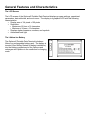
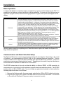
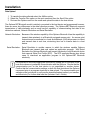
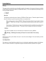
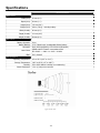
METROLOGIC INSTRUMENTS, INC. SP5500 OptimusS Series User’s Guide Copyright © 2006 by Metrologic Instruments, Inc. All rights reserved. No part of this work may be reproduced, transmitted, or stored in any form or by any means without prior written consent, except by reviewer, who may quote brief passages in a review, or provided for in the Copyright Act of 1976. Products and brand names mentioned in this document are trademarks of their respective companies. Table of Contents Introduction Product Overview .......................................................................................................................4 Scanner and Accessories...........................................................................................................4 General Features and Characteristics Multifunctional Keypad ...............................................................................................................6 The LCD Screen ........................................................................................................................7 The Lithium Battery ....................................................................................................................7 Installation Getting Started ...........................................................................................................................8 Basic Operation..........................................................................................................................9 Communication and Data Setup.................................................................................................9 Data Upload ............................................................................................................................. 11 System Module ........................................................................................................................12 System Menu Options ..............................................................................................................12 Application................................................................................................................................15 Programming the Terminal .......................................................................................................15 Programming the communication cradle ..................................................................................15 Troubleshooting ..................................................................................................................................16 Specifications ......................................................................................................................................17 Contact Information and Office Locations ...........................................................................................19 Safety Notices.....................................................................................................................................21 ii 3 Introduction Product Overview The SP5500 OptimusS Portable Data Terminals are robust and versatile scanning devices designed to provide exceptional performance, while enduring the demands of everyday use. The lithium-ion rechargeable battery provides the Optimus with more than 100 hours of operation. It is supported by a resourceful set of development tools, including a Windows-based program builder, “C” compiler, and “BASIC” compiler. The OptimusS has a fully integrated laser for scanning all 1D bar code symbologies, completely enclosed by the protective ergonomic housing. The built-in functionality of the Optimus makes it an excellent choice for numerous applications. In addition, when combined with the optional Bluetooth module it is the ideal solution for real time applications such as inventory control, shop floor management, warehousing operations, and distribution operations. Key Product Features • • • • • • • Up to 2 MB RAM capable of storing over 100,000 records Easy to use Optimizer program builder and download software Auto-backlit LCD display Audible and visual indications Built-in laser bar code scan engine capable of scanning all 1D bar code symbologies. Powered by rechargeable Lithium-ion battery Upload/download data via RS232 and USB interfaces (optional modem) Scanner and Accessories METROLOGIC PART NUMBERS. PART DESCRIPTION SP5502-6 OptimusS laser batch unit with 2MB RAM SP5535-6 OptimusS laser Bluetooth unit with 2MB RAM MI5500-614 OptimusS Charging/Communication cradle 4 General Features and Characteristics 1 4 9 5 2 3 8 6 7 Figure 1. Scanner Features ITEM NO. Figure 3. Product Label DESCRIPTION 1 Red Output Window (Laser Aperture) 2 Safety and Product label (Figure 3) 3 Speaker for audible indicators 4 LCD display 5 Multi-functional Keypad 6 Charging and communication contacts 7 IR Communication port 8 Battery Compartment release 9 Scan Button 1 6 2 3 4 5 Figure 2. Cradle Features ITEM NO. DESCRIPTION 1 Safety and Product label 2 RS232 communication port 3 Power Adapter port 4 LED power indicator 5 LED Transmission indicator 6 Rubber footpads Figure 4. Optimus and Cradle 5 General Features and Characteristics Multifunctional Keypad 4 5 6 3 7 2 8 1 Figure 5.Keypad Features ITEM NO. KEY NAME 1 POWER 2 ALPHANUMERIC 3 BS 4 ENTER 5 SCAN 6 ESC 7 ARROW ALPHA() 8 FUNCTION(FN) DESCRIPTION Power On/Off. To prevent an accidental power down, it requires about 1.5 sec of continuous pressing to turn On/Off the power. Alphanumeric These 10 keys can be used for either alpha characters or numerical input. (See Item 8 for further description of key operation) Back Space This key can be used to toggle back one space or if pressed down longer than one second, a clear code will be sent Enter. There are two enter keys on the side of the scan key. Normally the enter keys are used for command execution or input confirmation. Scan a bar code. Pressing this button will trigger the scanner to read a bar code Escape. This key is used to stop and exit current operation Arrow.The two arrow keys located below the Scan key are used to toggle up and down between menu selections. The toggle key for Alphabet/Numeral input. When the system is in alpha-mode, a small icon will be shown in the lower right corner of the display. Each numeric key can be used to generate one of the three capital letters located on that number key. For example, numeral 2 can be used to produce A, B, or C. Pressing the same key twice within one second, will produce the letter B. Pressing the same key without halting longer than one second, will allow the user to toggle through the three letters. When the key has been depressed for longer than one second or another key has been pressed, the unit will send the real key code to the application program. The function key. This key cannot be activated alone; it must be pressed with one of the numeric keys at the same time. For example, FN + 1 generates function #1, FN + 2 generates function #2, etc (up to 9 functions). Also, this key can be combined with the UP/DOWN arrow keys to adjust the contrast of the LCD. And when this key is combined with the ENTER key, it will turn ON/OFF the backlight. 6 General Features and Characteristics The LCD Screen The LCD screen of the OptimusS Portable Data Terminal displays program settings, operational parameters, data collected, and much more. The display is a graphical LCD with the following characteristics: y Display area of 64 pixels x 100 pixels y Resolution: y Maximum of 8 lines x 16 characters y Minimum of 4 lines x 12 characters y Displays alpha-characters, numbers, and symbols y Automated back light The Lithium-Ion Battery The OptimusS Portable Data Terminal includes a lithium-ion rechargeable battery pack. The battery is inserted (See Getting Started for battery installation) into the battery compartment of the Optimus and recharges with Optimus in the cradle and in charging mode. Figure 6 Lithium-Ion Battery 7 Installation Getting Started The OptimusS Portable Data Terminal (PDT) requires minimal effort to begin functional operation for data collection in any application. In order to get started the unit must have a fresh battery inserted into the battery compartment. 1. Access the battery compartment by removing the battery cover (See Figure 7). To remove the cover, press the cover release down and slide the cover away form the unit. 2. Insert the Li-ion battery into the battery compartment, battery information side up and battery contacts to the bottom, at an angle with the battery contacts inserted first. 3. Push the Li-ion battery the remainder of the way into the compartment. The battery will fit snuggly into place. 4. Close the battery compartment by sliding the battery cover toward the scan head until the cover locks into place. 3 1 Item No. Description 1 Li-ion battery 2 Battery contacts 3 Battery cover 2 Figure 7 Battery Compartment Features 5. Turn the unit over, so the keypad is visible and hold down the power button . 6. The LCD graphical display will display a menu and an audible indicator will sound to signify that the Optimus has been powered up properly. 7. Using the arrow keys select the Run Program option. 8. Scan a bar code. Note: The OptimusS comes with a default program loaded that allows users to scan items and enter their quantity. For information on how to create these programs, please refer to the Optimizer manual. 8 Installation Basic Operation In order for the Optimus to operate properly, an application program must be loaded onto the PDT. It is possible for the Optimus to power up without at active application. On power up if the Optimus has no application program loaded, then the following Application Program menu options will appear on the display: MENU OPTIONS. Download Activate Upload DESCRIPTION This option allows the user to download application programs (*.SHX), BASIC run-time (bas.ops.shx), BASIC programs (*.SYN) or font files to the terminal. There are 6 resident locations and one Active Memory. A maximum of 7 programs can be downloaded to the terminal. The application program downloaded to the Active Memory will be the only activate program running. In order to activate one of the other programs, immediately after downloading, input a name for the program desired or just press the enter key to keep its current name if one is applicable. This will enable the user to download the program. The application program’s type, name, and size will be shown on the list of programs when entering the Download or Activate menu of the Program Manager. The file type is a small letter that follows the program number (01~06), it can be either ‘b’, ‘c’ or ‘f’ which represents BASIC program, C program or font file respectively. The program name is up to 12 characters and the program size is in units of K bytes. NOTE: In order to delete a program, select the program designated for deletion. From the program information screen, press the Alpha/Function key, then zero. This option will enable the use to activate one of the resident programs. In order to accomplish this, the user must copy one of the 6 resident programs to the Active Memory. Upon activation of the new program the original program in the Active Memory will be replaced. Note: A font file cannot be activated, and a BASIC program cannot be activated if the BASIC run-time does not exist. The Upload option gives the user additional method for retrieving an application program. It allows a user to transmit the application programs to a host PC or another terminal. This function also allows a terminal to be cloned without going through a PC. Selecting and successfully completing one of these three menu options will enable the OptimusS to begin functional operation. Communication and Data Collection Setup The OptimusS Series has various ways of communicating with a host device. Depending on the model of Optimus, it can communicate via RS232, USB, or via a wireless Bluetooth connection. The two models available are the OptimusS Batch (SP5502) and OptimusS/Bluetooth (SP5535). These two models have various ways of data collection as well. Depending on the model it may store the data on the terminal itself or transmit live data back to a host device. The SP5502 stores data in the unit and has the ability to utilize a RS232 or USB connection to communicate to a host device for both application program downloads and data uploads. The SP5502 includes either a USB or RS232 cable. In order to begin an application download or data transfer the following steps would need to be followed. 1. Remove the Optimus cradle, the power supply, and either the USB or RS232 cable from the box. 2. Plug the power supply into a power outlet and insert the other end into the cradle. The red LED on the cradle will illuminate if the power supply is connected correctly. 9 Installation 3. Follow steps a and b a. For the RS232 cable plug the 9 pin serial connector into a serial port on the host device. Plug the opposite end into the communication port of the cradle. b. For the USB cable plug the USB end of the cable into an appropriate communication port on the host device and the opposite end of the cable into the communication port of the cradle*. 4. Power up the Optimus and select the Utilities option. 5. This will open additional menu options. Select the Transfer Files option. 6. Select Get Program on the next menu. The unit is now ready to download an application program. 7. Place unit in cradle and download the appropriate application program. 8. Once the Optimus has received the application program the unit is ready for scanning and collecting data. The Optimus Bluetooth is similarly setup, but the Bluetooth capability makes it necessary to take a few additional steps. Prior to downloading applications and transferring files an operation known as Bluetooth pairing must be performed. Bluetooth pairing is what happens when two Bluetooth enabled devices agree to communicate with one another. When this happens, the two devices join what is called a trusted pair. When one device recognizes another device in an established trusted pair, each device automatically accepts communication, bypassing the discovery and authentication process that normally happen during Bluetooth interactions. To setup the Bluetooth pairing follow steps 1-8. 1. With Optimus powered off press and hold the 7, 9, and power keys. The System Module menu will appear on screen. 2. Using the arrows select the Bluetooth Menu option. 3. Select Pairing Test from the list of options that appears using the arrow keys. The message “Inquiring … Please wait” will appear on the display. 4. The name of Bluetooth enabled devices will appear on the display. Using the arrow keys highlight the appropriate host device name and press the enter key to select that device. 5. The menu will appear on the display. Select the Serial Port** option. And enable the appropriate serial port options. 6. Press “ESC” to start Bluetooth pairing. 7. Successful pairing has been completed when “Connect OK!! Update Freq. Devices” appears on the display. Additionally the display on the Bluetooth enabled host device will have notification popup that indicates a Bluetooth device has been connected. 8. Power off the Optimus. Upon completion of the pairing process, and depending on the active application program, the user will be able to begin data transmission via the Bluetooth communication. It is important to note that when setting up the Optimus for Bluetooth pairing, that if the host device has enabled Bluetooth security settings, then the Optimus must match those settings in order for the pairing to be successfully completed. *A software driver is required for proper installation. The driver is included with the installation CD provided with each Optimus. In addition the driver can be downloaded from http://www.metrologic.com. ** It is important to note that this method of BT pairing is for “Serial Port Profile” only. To connect to the BT access point, please contact Metrologic representative. 10 Installation Data Upload 1. To transfer the data collected select the Utilities option. 2. Select the Transfer Files option on the next menu and then the Send Files option. 3. Re-insert the Optimus unit into the cradle and upload the data to the host device. The OptimusSBT Bluetooth model is similarly connected to the host device and programmed however, there are some key differences in the data collection process. The OptimusSBT Bluetooth supports transmission of data wirelessly and as such has the capability of communicating that data in two distinctive methods, Network Emulation and Serial Emulation. Network Emulation: Because of the wireless capability of the Optimus Bluetooth it has the capability to transmit data wirelessly to a Bluetooth equipped access point. An access point that exists and is connected to a Local Area Network (LAN) allows users to collect and transmit data in real time, minimizing time lost to transfer data to a host device. Serial Emulation: Serial Emulation is another manner in which the wireless capable Optimus Bluetooth can transmit data and upload an application program. With Serial Emulation the Optimus Bluetooth can transmit wirelessly to any Bluetooth device that supports Serial Port Profile (SPP). The SPP supported device also allows users to download an application program to the OptimusSBT Bluetooth wirelessly. It is important to note that plugging the Optimus into a serial port or USB port on the host device does not guarantee communication with the Optimus. Ensure that the communication port on the host device is not populated by another device. Confirm that the communication settings on both the host device and the Optimus correspond prior to a program download or data upload. The communication port settings on the host device to verify are the download/upload method, port number, and baud rate (For further detail see the Optimizer User’s Guide). 11 Installation The System Module The system module on the Optimus is another useful tool included with the Optimus. It provides information about the Optimus and access to the system menu for configuring the Optimus. In order to access the system module, follow the instructions below: 1. With the Optimus powered off press down and hold the 7, 9, and power button. 2. An audible indicator will sound to indicate that the Optimus is powered on. 3. The Optimus will display the system menu. The system menu will list a number of options: • • • • • • Information Settings Tests Memory Power Load Program Note: The different OptimusS models may have varying menu options. System Menu Options Depending on the application program that is active on the Optimus, there are number of settings and options that may be selected for both setup and testing. The tables show a number of those settings and their descriptions. Information The Information option provides information about the Optimus including: • • • • • Hardware Version Serial Number Manufacturing Date Application Program Version Hardware Configurations 12 Installation Settings SETTING Clock Backlight ON Period CPU Speed Powering Off the Terminal Power On Options Key Click System Password DESCRIPTION DEFAULT Set date and time for the system. Set the duration for the keyboard/LCD backlight N/A the light goes off after 20 seconds Set CPU running speed. There are five speeds available: Full speed, half speed, quarter speed, eighth speed and sixteenth speed. Set time threshold for automatically power off when no operation is taking place during that specified period. If this value is set to zero, this function will be disabled. There are two possible selections: Program Resume, which starts from the program being used during the last session before the last power-off; and Program Restart, which starts with a new program. Select a tone for the beeper or disable the beeper when the user presses a key button. Set a password to protect the user from entering the system menu. Full speed 10 minutes Program Resume Enable no password is set Tests The OptimusS has numerous tests available to the user for both operation and diagnostics. Depending on the application program that is in the active memory will determine which tests can be performed and are available to the user. The following table provides a description of the available tests. SETTING Reader Buzzer LCD & LED Keyboard Memory DESCRIPTION DEFAULTS To test the reading performance of the scanner. The following symbologies are enabled for the Reader test. All other symbologies will need to be enabled via programming. Default Bar codes: Code 39, Industrial 25, Interleave 25,Codabar, Code 93, Code 128, UPCE, UPCE with ADDON 2, UPCE with ADDON 5, EAN8, EAN8 with ADDON 2 EAN8 with ADDON 5, EAN13, EAN13 with ADDON 2, EAN13 with ADDON 5 To test the buzzer with different Frequency/Duration. Press ENTER key to start and then press any key to stop the test. To test LCD display and LED indicator. Press ENTER key to start and then press any key to stop the test. To test the rubber keys. Press a key and the result will be shown on the LCD display. Note that the FN key should be used in conjunction with numeral keys. To test the data memory (SRAM). Note after the test, the contents of the memory space will be wiped out. Warning: This test erases any data stored in the terminal. 13 Installation Memory The menu option provides the user with ability to gather information on the amount of memory available on the Optimus, as well as the ability to initialize the memory. This is accomplished by choosing one of the two available selections. 1. Size Info. 2. Initialize Size Info. The Optimus contains two types of memory, SRAM and Flash memory. These two types of memory allow the Optimus to perform operational tasks at an optimal level. Static random access memory (SRAM): Memory that retains data as long as power is being supplied. SRAM does not have to be periodically refreshed and provides quick access to data. Flash memory: Flash memory is a type of constantly-powered nonvolatile memory that can be erased and reprogrammed easily. This allows users to program the Optimus effortlessly. Initialize This selection enables the user of the Optimus to initialize the memory (SRAM). Warning: Initializing the memory will erase the current data of the memory. Power Selecting the power option allows the user to view the actual voltages of the main battery and the backup battery. Load Application The selection of Load Application enables the user to download an application program to the Optimus. Note: For further information on application program downloads see the Optimizer User’s guide. 14 Installation Application The Application module runs on top of the System module. The OptimusS Series Portable Data Terminals are preloaded with the Optimizer’s run-time program and the following menu will be shown upon powering the unit up: Models (SP5502 and SP5535): 1. Run Program 2. Utilities Utilizing the arrow keys select the menu option and execute it by pressing the ENTER key. For certain models of the OptimusS Series the Data Optimizer program may need to be used in order to handle the in-coming and out-going data to and from a host device. For detailed information, please refer to “Optimizer User’s Guide” and “DataOptimizer User’s Guide”. Note: If the Application Generator is used to create the application program, it will be necessary to download it to the terminal. Programming the terminal There are three software tools available for developing application programs for the terminal. • • • The Optimizer Program Builder The “BASIC” Compiler The “C” Compiler For detailed information, please consult the appropriate manual or contact Metrologic Instruments, Inc.. Programming the communication cradle The communication cradle of the OptimusS Portable Data Terminal supports serial IR interface only. If a customized PC application has been developed for communication with the terminal via the cradle, it will be necessary to first configure the cradle through programming. There is a DLL available for this purpose. For more information, please contact Metrologic Instruments, Inc.. 15 Troubleshooting SYMPTOM DESCRIPTION Make sure the battery is inserted and charged. Does not power up after pressing POWER key. Cannot transmit data or programs to/from the terminal Keypad does not work properly Charge the battery and check the charging status. If no charging information shown on the display, reload the battery and check if the battery is properly installed then try again. Call for service if problem persists. Check if the cable is plugged tightly into host device and cradle. Check if host communication parameters (COM port, baud rate, data bits, parity, and stop bit) match with the Terminal's. Verify that the communication port on the host device is not in use by another device. Turn off the power then enter the system menu. From the system menu, select the Test and then its sub-item KBD. Perform the key-in test. Call for service if problem persists. Check if the bar codes used are enabled Scanner does not scan Check if battery-low indicator is shown on the LCD display. If yes, charge the battery Call for service if problem persists. Open the battery cap and re-load the battery. Abnormal responses Enter system menu. Run diagnostic test. Call for service if problem persists. 16 Specifications OPTIMUSS SERIES OPERATIONAL Light Source: Normal Depth of Field: Width of Scan Field: Visible Laser Diode (VLD) @ 650 nm 20 mm - 202 mm 0.33 mm (13 mil) (.75"- 8.75") bar code 290mm (11.4”) @ 222 mm (8.75”) Single-Line Scan Speed: No. of Scan Lines: Min Bar Width: 100 scan lines per second 1 0.127 mm (5.0 mil) Decode Capability: All standard 1-D bar codes including RSS-14, RSS-Expanded, and RSS-14 Limited Print Contrast: No. Characters Read: Beeper Operation: CPU: Program Memory: Data Memory: Display: Display Resolution: 35% minimum reflectance difference Up to 80 data characters Maximum number will vary based on symbology and density. 7 tones or no beep 16-bit CMOS, low power consumption 1 MB Flash ROM 2 MB SRAM LCD 100 x 64 pixels, back-lit 8 lines x 16 Characters (max), 4 Lines x 12 characters (min) Bluetooth Version: 1.2 Bluetooth Profiles: Bluetooth Network Encapsulation Profile(BNEP), Serial Port Profile (SPP) Communication (Unit): IrDA, CradleIR or Bluetooth (modem optional) Communication (Cradle): RS232 or USB Application Development: Windows-based Optmizer; optional C & BASIC compilers 17 Specifications OPTIMUSS SERIES MECHANICAL Width (Unit): 55 mm (2.2") Depth (Unit): 28 mm (1.1") Height (Unit): 137 mm (5.4") Weight (Unit): 4.9 oz (140 g) – including battery Width (Cradle): 92 mm (3.6") Depth (Cradle): 110 mm (4.3") Height (Cradle): 58 mm (2.3") ELECTRICAL Battery Operation: Battery Backup: Operation: Laser Class: EMC: Li-ion 3.7V, 700mA hours, rechargeable lithium battery Over 100 hours(Batch), Over 36 hours (Bluetooth) CDHR and IEC Class 2 in accordance with IEC 60825 – 1:1993 + A1:1997 + A2:2001 FCC, Class B ENVIRONMENTAL Operating Temperature: Storage Temperature: Humidity: Shock Resistance: 0°C to 55°C (32°F to 131°F) -20°C to 60°C (-4°F to 140°F) 5% to 95% relative humidity, non-condensing 1.2 m (4’) drop onto concrete Figure 8 Scan Areas 18 Contact Information and Office Locations Corporate Headquarters Metrologic Instruments, Inc. 90 Coles Road Blackwood, NJ 08012-4683 Tel: 856-228-8100 Fax: 856-228-6673 (Sales) Fax: 856-228-1879 (Marketing) Fax: 856-228-0653 (Legal/Finance) Email: [email protected] European, Middle East and African HQ & Germany Office Eastern Europe and Middle East Metrologic Instruments GmbH Dornierstrasse 2 82178 Puchheim Munich, Germany Tel: 49-89-89019-222 Fax: 49-89-89019-173 Email: [email protected] Asian Headquarters - Singapore Singapore Metrologic Asia (Pte) Ltd 50 Kallang Avenue #01-02 Noel Corporate Building Singapore 339505 Tel : (65) 6842-7155 Fax : (65) 6842-7166 Email: [email protected] North America Metrologic The Americas 1571 Imperial Way Suite B West Deptford, NJ 08066 Tel: 1.856.537.6400 Fax: 1.856.537.6474 Email: [email protected] France Metrologic Eria France SA 69 Rue de la Belle Etoile ZI Paris Nord II, BP 50057 95947 – ROISSY CDG CEDEX Tel: +33 (0) 1 48.63.78.78 Fax: +33 (0) 1 48.63.24.94 Email: [email protected] China MTLG AutoID Instr. (Shanghai) Co.,Ltd Room 1419, No.1 Ji long Road Waigaoqiao Bonded Zone Shanghai 200000 Tel: 86-21-58692780 Fax:86-21-58692782 Email: [email protected] Adaptive Optics Associates (AOA) Ten Wilson Road Cambridge, MA 02138-1128 Tel: 617-806-1400 Fax: 617-806-1899 Email: [email protected] Italy Metrologic Instruments Italia srl Via Emilia 70 40064 Ozzano dell’Emilia (BO) Tel: +39 0 51 6511978 Fax: +39 0 51 6521337 Email: [email protected] China Suzhou Sales Office BLK A, Room# 03/03-04 No.5 Xinghan Str., Xinsu Industrial Sq China-Singapore Suzhou Industrial Park,Suzhou, PRC Tel: 86-512-67622550 Fax: 86-512-67622560 Email: [email protected] Omniplanar 1571 Imperial Way Suite A West Deptford, NJ Tel: 856.537.6100 Fax: 856.537.6116 Email: [email protected] Poland Metrologic Instruments Poland Sp.z o.o Poleczki 21 02-822 Warsaw, Poland Tel: +48 (22) 545 04 30 Fax:+48 (22) 545 04 31 Email:[email protected] 19 China Guangzhou Sales Office Room 2307 Foreign Economic and Trade Bldg #351 Tianhe Road Guangzhou City, Guangdong Province, PRC Tel: 86-20-38823476 Fax: 86-20-38823477 Email: [email protected] Contact Information and Office Locations South America and Central America Brazil Metrologic do Brasil Ltda. Rua da Paz 2059 CEP 04713-002 Chácara Santo Antônio São Paulo, SP, Brasil Tel: 55-11-5182-8226 Fax: 55-11-5182-8315 Email: [email protected] Outside Brazil Metrologic South America Rua da Paz 2059 CEP 04713-002 Chácara Santo Antônio São Paulo, SP, Brasil Tel: 55-11-5182-7273 Fax: 55-11-5182-7198 Email: [email protected] European, Middle East and African Headquarters Metrologic Instruments GmbH Dornierstrasse 2 82178 Puchheim Munich, Germany Tel: 49-89-89019-0 Fax: 49-89-89019-200 Email: [email protected] Germany, Austria and Switzerland Metrologic Instruments GmbH Dornierstrasse 2 82178 Puchheim Munich, Germany Tel: 49-89-89019-0 fax: 49-89-89019-200 Email: [email protected] European, Middle East and African Headquarters Russia Metrologic Russia Bolshaya Novodmitrovskaya 14 RU-125015 Moscow Russia Tel: +7 095 730 7424 Fax: +7 095 730 7425 Email: [email protected] Spain Metrologic Eria Ibérica, SL Julián Camarillo 29, D-1 28037 Madrid Tel: +34 913 272 400 Fax: +34 913 273 829 Email: [email protected] Metrologic European Repair Ctr (MERC) Metrologic Eria Ibérica, SL C/ Alfonso Gomez, 38-40, 1D 28037 Madrid Tel: +34 913 751 249 Fax: +34 913 270 437 United Kingdom Metrologic Instruments UK Ltd 58 Tempus Business Centre Kingsclere Road, Basingstoke Hampshire RG21 6XG Tel: +44 (0) 1256 365900 Fax: +44 (0) 1256 365955 Email: [email protected] Kingsclere Road, Basingstoke Hampshire RG21 6XG Tel: +44 (0) 1256 365900 Fax: +44 (0) 1256 365955 Email: [email protected] 20 Asian Headquarters - Singapore China Beijing Sales Office Tower A, 5th Floor, Unit 5204 China Intn'l Science and Tech Convention Ctr No. 12 Yu Min Road Chao Yang Dist Beijing China 100029 Tel/Fax: 86 10 82253472 Email: [email protected] India Metrologic India 403, 4th Floor Carlton Towers No. 1, Airport Road Bangalore, India 560 008 Tel: +91 80 51256718 Fax: +91 80 51256719 Email: [email protected] Japan Metrologic Japan Co., Ltd. Matsunoya Building, 6 Floor 3-14-8 Higashiueno Taitou-ku, Tokyo 110-0015 Japan Tel: 81-3-3839-8511 Fax: 81-3-3839-8519 Email: [email protected] Safety Notices This equipment has been tested and found to comply with the limits for a Class B digital device, pursuant to Part 15 of the FCC Rules. These limits are designed to provide reasonable protection against harmful interference in a residential installation. This equipment generates, uses, and can radiate radio frequency energy and, if not installed and used in accordance with the instructions, may cause harmful interference to radio communications. However, there is no guarantee that interference will not occur in a particular installation. If this equipment does cause harmful interference to radio or television reception, which can be determined by turning the equipment off and on, the user is encouraged to try to correct the interference by one of the following measures: • • • • Reposition or relocate the receiving antenna. Increase the separation between the equipment and receiver. Connect the equipment into an outlet on a circuit different from that to which the receiver is connected. Consult the dealer or an experienced radio/TV technician for help. This device complies with Part 15 of the FCC Rules. Operation is subject to the following two conditions: (1) This device may not cause harmful interference, and (2) this device must accept any interference received, including interference that may cause undesired operation. Any changes or modifications not expressly approved by the party responsible for compliance could void the user's authority to operate this equipment. 21