1
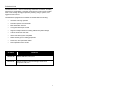
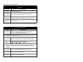
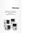
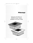
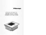
METROLOGIC INSTRUMENTS, INC.
MS7320 InVista™ Series
Installation and User’s Guide
LOCATIONS
CORPORATE HEADQUARTERS
North America
Metrologic Instruments, Inc.
90 Coles Road
Blackwood, NJ 08012-4683
Customer Service: 1-800-ID-METRO
Tel: 856-228-8100
Fax: 856-228-6673
Email: [email protected]
Internet: www.metrologic.com
EUROPEAN HEADQUARTERS
Germany,
Middle East and Africa
Metrologic Instruments GmbH
Dornierstrasse 2
82178 Puchheim b.
Munich, Germany
Tel: +49 89 89019 0
Fax: +49 89 89019 200
Email: [email protected]
Germany Email: [email protected]
Spain
Metrologic Eria lbérica SL
Julián Camarillo 29, D-1
Edificio Diapasón
28037 Madrid
Tel: +34 913 272 400
Fax: +34 913 273 829
Email: [email protected]
Italy
Metrologic Instruments Italia srl
Via Emilia 70
40064 Ozzano dell’Emilia (BO)
Tel: +39 0 51 6511978
Fax: +39 0 51 6521337
Email: [email protected]
France
Metrologic Eria France SA
69 Rue de la Belle Etoile
ZI Paris Nord II, BP 50057
95947 – ROISSY CDG CEDEX
Tel: +33 (0) 1 48.63.78.78
Fax: +33 (0) 1 48.63.24.94
Email: [email protected]
United Kingdom
Metrologic Instruments UK Limited
58 Tempus Business Centre
Kingsclere Road, Basingstoke
Hampshire RG21 6XG
Tel: +44 (0) 1256 365900
Fax: +44 (0) 1256 365955
Email: [email protected]
Singapore
Metrologic Asia (Pte) Ltd
No. 8 Kaki Bukit Place
th
4 Floor
Singapore 416186
Tel: 65-6842-7155
Fax: 65-6842-7166
Email: [email protected]
China
Metro (Suzhou) Technologies Co., Ltd.
221 Xing Hai Street
Suzhou Industrial Park
Suzhou, China
215021
Tel: 86-512-62572511
Fax: 86-512-62571517
Email: [email protected]
Japan
Metrologic Japan Co., Ltd.
Matsunoya Building, 6 Floor
3-14-8 Higashiueno
Taitou-Ku, Tokyo 110-0015 Japan
Tel: 81-03-3839-8511
Fax: 81-03-3839-8519
Email: [email protected]
Brazil
Metrologic do Brasil Ltda.
Rua da Paz 2059
CEP 04713-002
Chácara Santo Antônio
São Paulo, SP, Brasil
Tel: 55-11-5182-8226
Fax: 55-11-5182-8315
Email: [email protected]
Outside Brazil
Metrologic South America
Rua da Paz 2059
CEP 04713-002
Chácara Santo Antônio
São Paulo, SP, Brasil
Tel: 55-11-5182-7273
Fax: 55-11-5182-7198
Email: [email protected]
ASIA
SOUTH AMERICA
Copyright
© 2002 by Metrologic Instruments, Inc. All rights reserved. No part of this work may be reproduced, transmitted, or stored
in any form or by any means without prior written consent, except by reviewer, who may quote brief passages in a review,
or provided for in the Copyright Act of 1976.
Products and brand names mentioned in this document are trademarks of their respective companies.
ii
TABLE OF CONTENTS
Introduction...........................................................................................................1
Scanner and Accessories.....................................................................................2
Installation for OCIA Interface ..............................................................................4
Installation for Keyboard Wedge Interface ...........................................................5
Installation for Stand-Alone Keyboard Interface ...................................................6
Installation for USB Interface................................................................................7
Installation for RS232 or Light Pen Interfaces ......................................................8
Installation for IBM 46xx Interface ......................................................................10
Installation of an Auxiliary Scanner.....................................................................11
Scanner Parts.....................................................................................................14
Maintenance .......................................................................................................14
Cable Cover Installation and Removal ...............................................................15
Face Plate Removal ...........................................................................................15
Scanner Labels...................................................................................................16
Audible Indicators ...............................................................................................17
Visual Indicators .................................................................................................18
Failure Modes .....................................................................................................19
Power Save Modes and the Multi-Function Button.............................................20
Scan Volume ......................................................................................................22
Depth of Field by Minimum Bar Code Element Width ........................................23
Flex Stand Installation ........................................................................................25
EAS Deactivation Antenna .................................................................................27
Troubleshooting Guide .......................................................................................28
Design Specifications .........................................................................................33
RS232 Demonstration Program..........................................................................35
Applications and Protocols .................................................................................36
Default Settings ..................................................................................................37
Scanner and Cable Terminations .......................................................................43
Limited Warranty ................................................................................................47
Notices................................................................................................................48
Patents ...............................................................................................................50
Index...................................................................................................................51
iii
INTRODUCTION
™
The MS7320 InVista offers an outstanding combination of features, versatility,
performance, and durability. This fixed mount laser bar code scanner provides
ease of use and high throughput speeds by featuring a large, dynamic, and
aggressive scan volume.
The MS7320 is equipped with a multitude of standard features including:
•
Automatic scanning operation
•
Firmware updates via Flash ROM
•
EAS deactivation antenna
•
A Programmable Depth of Field
•
Supports multiple interfaces including USB and Keyboard Wedge
•
Custom edit the bar code data
•
OPOS and JPOS system compatible
•
RS232 auxiliary port for adding peripherals
•
PowerLink, user replaceable cables
•
Field replaceable outer window
SCANNER
INTERFACE
MS7320-13
RS232, IBM 46xx, OCIA, Aux
MS7320-37
RS232, Light Pen, Keyboard Wedge, Stand-Alone
Keyboard, USB, Aux
1
SCANNER AND ACCESSORIES
B ASIC K IT
Part #
MS7320
00-02407A-1
&
00-02407A-2
00-02896
52-52511A
Description
InVista Series Scanner
®
MetroSelect Programming Guide Two Book Set
MS7320 InVista Series Installation and User’s Guide
24” EAS Cable
Guides also available for download at www.metrologic.com.
O PTIONAL ACCESSORIES
Part #
54-54xxx*
Description
Straight PowerLink Cable with built in power jack.
2.1 m (7') cord with short strain relief
xxx* specifies connection to the host.
Contact a customer service representative for additional information.
54-54002
MVC**
**
2
Keyboard Wedge PowerLink Cable with Adapter Cable
Metrologic Voltage Converter Cable,
+12VDC to +5.2VDC or -12VDC to +5VDC
Contact a Metrologic Customer Service representative for additional
information on Metrologic’s MVC cable series and the host connections
available.
54-54020
Stand Alone Keyboard Wedge PowerLink Cable
54-54165
USB PowerLink Cable (Type A)
54-54667
RS232 AUX PowerLink Cable
SCANNER AND ACCESSORIES (CONTINUED)
O PTIONAL ACCESSORIES
Part #
Description
AC to DC Power Transformer - Regulated 5.2V@650 mA output
45-45593
120V United States
45-45591
220V – 240V Continental European
45-45592
220V – 240V United Kingdom
45-45483
Flex Stand
R EPLACEMENT P ARTS
Part #
Description
46-46624
Everscan Window Face Plate
46-46625
Standard Window Face Plate
Other items may be ordered for the specific protocol being used. To order
additional items, contact the dealer, distributor or call Metrologic’s Customer
Service Department at 1-800-ID-METRO or 1-800-436-3876.
3
INSTALLATION FOR OCIA INTERFACE
1.
Turn off the host system.
2.
Connect the MVC cable to
the 10-pin OCIA interface jack. It is
nd
the 2 round opening from the left
side of the MS7320 (see figure 1).
3.
Connect the other end of the MVC
cable to the host.
Before continuing verify that the MVC
cable is connected to the appropriate
interface jack on the scanner. An
incorrect cable connection can cause
communication problems or potential
damage to the scanner.
Plugging the scanner into the
serial port of the PC does not
guarantee that scanned
information will appear at the
PC. A software driver and
correct configuration settings
are also required for proper
communication.
4.
Turn on the host system.
5.
Scan the Load OCIA Defaults bar
code to configure the MS7320 for
OCIA communication.
6.
Figure 1: OCIA, Interface
Load OCIA Defaults
Snap on the cable cover.
³
9
9
9
9
9
3
For additional communication options for OCIA interfaces refer to the
MetroSelect Programming Guide (MLPN 00-02407A-1 & -2).
Caution:
To maintain compliance with applicable standards, all circuits connected to the scanner must meet the
requirements for SELV (Safety Extra Low Voltage) according to EN 60950.
To maintain compliance with standard CSA C22.2 No. 60950-00/UL 60950 and norm EN 60950, the power
source should meet applicable performance requirements for a limited power source.
4
INSTALLATION FOR KEYBOARD W EDGE INTERFACE
1.
Turn off the host system.
2.
Disconnect the keyboard from the host.
3.
Connect the PowerLink cable to the 10-pin
nd
KBW interface jack. It is the 2 round
opening from the left side of the MS7320
(see figure 2).
4.
Connect the “Y” end of the
PowerLink cable to the keyboard
and the keyboard port on the host.
If necessary use the male/female
adapter cable supplied with the scanner
for proper connections.
Before continuing verify that the
PowerLink cable is connected to the
appropriate interface jack on the scanner.
An incorrect cable connection can cause
communication problems or potential
damage to the scanner.
5.
Connect the external power supply
to the power jack on the PowerLink cable.
6.
Check the AC input requirements
of the power supply to make sure
the voltage matches the AC outlet.
7.
Connect AC power to the transformer.
The outlet should be near the equipment
and easily accessible.
8.
Scan the Load Keyboard Wedge Defaults
bar code to configure the MS7320 for
Keyboard Wedge communication.
9.
Turn on the host system.
10. Snap on the cable cover.
Figure 2: Keyboard Wedge Interfaces
Load Keyboard
Wedge Defaults
³
9
9
9
9
9
4
Caution:
To maintain compliance with applicable standards, all circuits connected to the scanner must meet the
requirements for SELV (Safety Extra Low Voltage) according to EN 60950.
To maintain compliance with standard CSA C22.2 No. 60950-00/UL 60950 and norm EN 60950, the power
source should meet applicable performance requirements for a limited power source.
5
INSTALLATION FOR STAND-ALONE KEYBOARD INTERFACE
1.
Turn off the host system.
2.
Disconnect the keyboard from the host.
3.
Connect the PowerLink cable to the 10-pin
Stand-Alone Keyboard interface jack. It is
nd
the 2 round opening from the left side of
the MS7320 (see figure 3).
4.
Connect the other end of the PowerLink
cable to the keyboard port on the host.
Before continuing verify that the
PowerLink cable is connected to the
appropriate interface jack on the scanner.
An incorrect cable connection can cause
communication problems or potential
damage to the scanner.
5.
Connect the external power supply to the
power jack on the PowerLink cable.
6.
Check the AC input requirements of the
power supply to make sure the voltage
matches the AC outlet.
7.
Connect AC power to the transformer.
The outlet should be near the equipment
and easily accessible.
8.
Figure 3: Stand-Alone Keyboard
Interface
Load Keyboard
Wedge Defaults
Scan 1St
³
Scan the two bar codes in numbered
sequence in order to configure the
MS7320 for Stand-Alone Keyboard
communication.
Note:
When scanning the bar codes, cover the
code not being scanned to ensure the
codes are read in the proper sequence.
9.
Turn on the host system.
10. Snap on the cable cover.
9
9
9
9
9
4
Enable Stand-Alone
Keyboard Wedge
Scan 2nd
³
5
1
5
5
1
5
Caution:
To maintain compliance with applicable standards, all circuits connected to the scanner must meet the
requirements for SELV (Safety Extra Low Voltage) according to EN 60950.
To maintain compliance with standard CSA C22.2 No. 60950-00/UL 60950 and norm EN 60950, the power
source should meet applicable performance requirements for a limited power source.
6
3
INSTALLATION FOR USB INTERFACE
1.
Turn off the host system.
2.
Determine if your application requires
USB Keyboard communication protocols
or USB Point-of-Sale communication
protocols.
3.
If you require USB Keyboard
communication protocols, skip to step 4.
If you require USB Point-of-Sale
communication protocols set the dip
switches shown in figure 4a to positions
1 and 2.
4.
Connect the PowerLink cable to the 10-pin
nd
USB interface jack. It is the 2 round
opening from the left side of the MS7320
(see figure 4b).
5.
Connect the other end of the USB cable to
the host.
Figure 4a: POS Dip Switch
Before continuing verify that the USB
cable is connected to the appropriate
interface jack on the scanner. An
incorrect cable connection can cause
communication problems or potential
damage to the scanner.
Plugging the scanner into the USB
port of the PC does not guarantee
that scanned information will appear
at the PC. A software driver and
correct configuration setting are also
required for proper communication.
6.
Scan the Enable USB Defaults bar code
to configure the MS7320 for USB
communication.
7.
Turn on the host system.
8.
Snap on the cable cover.
Caution:
Figure 4b: USB, Interface
Enable USB Defaults
³
9
9
9
9
7
8
To maintain compliance with applicable standards, all circuits connected to the scanner must meet the
requirements for SELV (Safety Extra Low Voltage) according to EN 60950.
To maintain compliance with standard CSA C22.2 No. 60950-00/UL 60950 and norm EN 60950, the power
source should meet applicable performance requirements for a limited power source.
7
INSTALLATION FOR RS232 OR LIGHT PEN INTERFACES
1.
Turn off the host system.
2.
Connect the PowerLink cable to the
10-pin RS232/Light Pen interface
st
jack. It is the 1 round opening
from the left side of the MS7320
(see figure 5).
3.
Connect the other end of the
PowerLink cable to the host.
Before continuing verify that the
PowerLink cable is connected to the
appropriate interface jack on the
scanner. An incorrect cable connection
can cause communication problems or
potential damage to the scanner.
4.
Connect the external power supply
to the power jack on the PowerLink
Cable.
5.
Check the AC input requirements of
the power supply to make sure the
voltage matches the AC outlet.
6.
Connect AC power to the
transformer. The outlet should be
near the equipment and easily
accessible.
7.
Scan the appropriate bar codes on
page 9 to configure the MS7320 for
RS-232 or Light Pen communication.
8.
Turn on the host system.
9.
Snap on the cable cover.
Figure 5: RS232 or
Light Pen Interface
Caution:
To maintain compliance with applicable standards, all circuits connected to the scanner must meet the
requirements for SELV (Safety Extra Low Voltage) according to EN 60950.
To maintain compliance with standard CSA C22.2 No. 60950-00/UL 60950 and norm EN 60950, the power
source should meet applicable performance requirements for a limited power source.
8
INSTALLATION FOR RS232 OR LIGHT PEN INTERFACES
Codes needed for Step 7 on page 8.
For RS232 Communication:
Recall Defaults
Scan 1
st
³
9
9
9
9
9
8
Enable RS-232
Scan 2
nd
³
4
1
5
5
5
4
For Light Pen Communication:
Recall Defaults
Scan 1
st
³
9
9
9
9
9
8
Enable Light Pen/Wand
Scan 2
nd
³
4
1
5
5
2
4
9
INSTALLATION FOR IBM 46XX INTERFACE
1.
Turn off the host system.
2.
Connect the MVC cable to the 10-pin
IBM 46xx interface jack. It is the
st
1 round opening from the left side of
the MS7320 (see figure 6).
3.
Connect the other end of the MVC
cable to the host.
Before continuing verify that the MVC
cable is connected to the proper
communication jack on the scanner.
Incorrect cable connection can cause
communication problems or potential
damage to the scanner.
Plugging the scanner into the serial port of the PC does not guarantee
that scanned information will appear at the PC. A software driver and
correct configuration setting are also required for proper
communication to occur.
4.
Turn on the host system.
5.
Scan the Load 46xx IBM Defaults bar
code to configure the MS7320 for
RS232/IBM communication.
6.
Snap on the cable cover
For additional communication
options for IBM interfaces refer to the
MetroSelect Programming Guide
(MLPN 00-02407A-1 & -2).
Figure 6: IBM 46xx Interface
Load 46xx IBM Defaults
³
9
9
9
9
9
5
Caution:
To maintain compliance with applicable standards, all circuits connected to the scanner must meet the
requirements for SELV (Safety Extra Low Voltage) according to EN 60950.
To maintain compliance with standard CSA C22.2 No. 60950-00/UL 60950 and norm EN 60950, the power
source should meet applicable performance requirements for a limited power source.
10
INSTALLATION OF AN AUXILIARY SCANNER
1.
Turn off the host system.
2.
Connect the round end of the PowerLink RS232 AUX cable
[ MLPN 54-54667A ] to the RS232 jack of the auxiliary scanner (see figure 7).
3.
Connect the other end of the PowerLink RS232 AUX cable into the 1 jack
from the left side of the MS7320. The Aux jack has a square opening.
st
The following Metrologic scanners can be used in the “Aux” input of the
MS7320: the MS9520, MS9540, MS6220, MS7120, MS6520, MS6720,
MS7220 or another MS7320.
Important: The MS7320 aux port requires the signals: transmit, receive,
RTS & CTS from the auxiliary scanner.
4.
Connect the MS7320/Host PowerLink* cable to the appropriate interface
jack on the back of the MS7320.
5.
Connect the other end of the MS7320/Host PowerLink cable to the Host.
6.
Connect the external power supplies for the auxiliary scanner and the
MS7320 to the power jacks on the two PowerLink cables.
Before continuing verify that the PowerLink cables are connected to
the appropriate interface jacks on the scanner. An incorrect cable
connection can cause communication problems or potential damage
to the scanner.
7.
Check the AC input requirements of both power supplies to make sure the
voltage matches the AC outlets.
8.
Snap on the cable cover.
9.
Connect AC power to the transformers. The outlets should be near the
equipment and easily accessible.
10. Configure the MS7320 for the appropriate interface configuration settings.*
Continued on page 12.
* The MS7320/host cable connection is interface dependent. Refer to the
installation steps provided for the type of interface required for your application.
Caution:
To maintain compliance with applicable standards, all circuits connected to the scanner must meet the
requirements for SELV (Safety Extra Low Voltage) according to EN 60950.
To maintain compliance with standard CSA C22.2 No. 60950-00/UL 60950 and norm EN 60950, the power
source should meet applicable performance requirements for a limited power source.
11
INSTALLATION OF AN AUXILIARY SCANNER
11. Configure the auxiliary scanner to send formatted data to the MS7320.
Normal slave mode operation will only require reserve Code 32 to be set in
the auxiliary scanner. The following bar code applies for all scanners,
except the MS6720, to be used as an auxiliary scanner. Contact a
Metrologic representative for additional information on the MS6720.
Reserve Code 32
³
1
2
4
8
1
7
Metrologic recommends disabling the beeper on the auxiliary scanner.
Refer to ‘Beeper Options’ in the Communications section of the
MetroSelect Configuration Guide (MLPN 00-02407A-1 & -2).
12. Configure the MS7320 to activate the auxiliary port. Enable the auxiliary
port and configure it to recognize slave formatted data with the following bar
code:
Enable Aux Port
³
13. Turn on the host system.
12
4
3
7
3
3
0
INSTALLATION OF AN AUXILIARY SCANNER
Figure 7:
Connector Orientation (Top)
Auxiliary Scanner Setup (Bottom)
13
SCANNER PARTS
Figure 8: Scanner Parts
n
o
p
q
r
s
t
u
v
Output Window (Laser Aperture)
Speaker (Under the Window Cover)
Replaceable Window Face Plate
Red LED (Top LED)
Green LED (Bottom LED)
Muli-Function Button (see page 20)
Cable Connection and Dip Switch Area
Cable Cover
Stand Foot
MAINTENANCE
Smudges and dirt can interfere with the proper scanning of a bar code.
Therefore, the output window will need occasional cleaning.
For the MS7320 glass window:
1. Spray glass cleaner onto lint free, non-abrasive cleaning cloth.
2. Gently wipe the scanner window.
For the MS7320 red window:
1. Use mild soap and water with lint free, non-abrasive cleaning cloth.
2. Gently wipe the scanner window.
14
CABLE COVER INSTALLATION AND REMOVAL
Figure 9:
Installing the Cable Cover (left).
Removing the Cable Cover
(bottom right).
FACE PLATE REMOVAL
Figure 10: Face Plate Removal
15
SCANNER LABELS
The MS7320 has 2 labels on the back of the unit. These labels contain the
model number, date of manufacture, serial number, and caution information. An
additional caution label is located under the window faceplate and a label noting
the jack interfaces is located under the connector cover. The following are
examples of these labels.
Figure 11: Scanner Labels
16
AUDIBLE INDICATORS
When the MS7320 scanner is in operation, it provides audible feedback. These
sounds indicate the status of the scanner. Eight settings are available for the
tone of the beep (normal, 6 alternate tones and no tone). To change the tone,
®
use the Multi-Function Button or refer to the MetroSelect Programming Guide.
One Beep
When the scanner first receives power, the green LED will turn on,
the red LED will flash and the scanner will beep once. (The red
LED will remain on for the duration of the beep.) The scanner is
now ready to scan.
When the scanner successfully reads a bar code, the red LED will
flash and the scanner beeps once (if programmed to do so). If the
scanner does not beep once and the red light does not flash, then
the bar code has not been successfully read.
Razzberry Tone
This is a failure indicator. Refer to failure modes page 19.
Three Beeps - during operation
When placing the scanner in program mode, the red LED will flash
while the scanner simultaneously beeps three times. The red and
green LEDs will continue to flash until the unit exits program mode.
Upon exiting program mode, the scanner will beep three times and
the red LED will stop flashing.
When configured, 3 beeps can also indicate a communications
timeout during normal scanning mode.
When using one-code-programming, the scanner will beep three
times (the current selected tone), followed by a short pause, a high
tone and a low tone. This tells the user that the single
configuration bar code has successfully configured the scanner.
Three beeps will also occur during a manual adjustment of the
beeper tone. With each short depression of the Multi-Function
Button, the new tone will be heard, followed by a short pause then
two more of the new current tones.
Three Beeps - on power up
This is a failure indicator. Refer to failure modes page 19.
17
VISUAL INDICATORS
There is a red LED and green LED on
the front of the MS7320. When the scanner is on, the
flashing or constant illumination of the LEDs indicates
the status of the current scan and the scanner.
Figure 12: LEDs
No Red or Green LED
The LEDs will not be illuminated if the scanner is not receiving
power from the host or transformer.
Steady Green
When the laser is active, the green LED is illuminated. The
green LED will remain illuminated until the laser is deactivated.
During the power save mode, the laser will turn on and off.
During this period, the green LED remains illuminated.
Steady Green and Single Red Flash
When the scanner successfully reads a bar code, the red LED
will flash and the scanner will beep once. If the red LED does
not flash or the scanner does not beep once, then the bar
code has not been successfully read.
Steady Green and Steady Red
After a successful scan, the scanner transmits the data to the
host device. Some communication modes require that the
host inform the scanner when data is ready to be received. If
the host is not ready to accept the information, the scanner’s
red LED will remain on until the data can be transmitted.
Flashing Green then Flashing Red
This indicates the scanner is in program mode. A razzberry
tone indicates that an invalid bar code has been scanned in
this mode.
or
If the unit is in sleep mode, each LED will flash once every 15
seconds.
Steady Red, Green off
This indicates the scanner may be waiting for communication
from the host.
18
FAILURE MODES
Figure 13: LEDs
Flashing Green and One Razzberry Tone
This indicates the scanner has experienced a laser subsystem
failure. Return the unit for repair at an authorized service
center.
Flashing Red and Green and
Two Razzberry Tones
This indicates the scanner has experienced a motor failure.
Return the unit for repair at an authorized service center.
Continuous Razzberry Tone with both LEDs off
If, upon power up, the scanner emits a continuous razzberry
tone, then the scanner has an electronic failure. Return the
unit for repair at an authorized service center.
Three Beeps - on power up
If the scanner beeps 3 times on power up then, the nonvolatile
memory that holds the scanner configuration has failed.
Return the unit for repair at an authorized service center.
19
POWER SAVE MODES AND THE MULTI-FUNCTION BUTTON
The MS7320 has five programmable power save modes. Refer to the
MetroSelect Programming Guide for additional information on Power Save
Modes.
1.
Blink Power Save Mode (Default):
“Blinks” the laser OFF & ON after a programmed period of non-use.
When the scanner recognizes a bar code it will exit the Blink mode.
2.
Laser Off Power Save Mode:
Turns the laser OFF after a programmed period of non-use.
The motor continues to spin allowing for a faster “wake” up time. Pressing
the Multi-Function button will “wake” the scanner from the Laser Off power
save mode (see figure 17).
3.
Laser & Motor Off Power Save Mode:
Turns the laser and motor OFF after a programmed period of non-use.
Pressing the Multi-Function button will “wake” the scanner from the power
save mode (see figure 17). This mode is the only power save mode that can
be activated by the Multi-Function Button (see figure 16). This mode’s
“wake up” time is slightly longer due to the motor’s need to restart.
4.
Dual Action Power Save Mode #1:
“Blinks” the laser OFF & ON after a programmed period of non-use turns the
laser and motor OFF at thirty-minute intervals.
Example:
If the power save timeout
is set to 15 minutes.
Last
Scan
Laser starts
“Blinking”
Laser & Motor
turn OFF
Pressing the Multi-Function button will “wake” the scanner from the power
save mode (see figure 17).
5.
Dual Action Power Save Mode #2:
Turns the laser OFF after a programmed period of non-use then turns the
motor OFF after thirty-minute intervals.
Example:
If the power save timeout
is set to 15 minutes.
Last
Scan
Laser turns
OFF
Motor turns
OFF
Pressing the Multi-Function button will “wake” the scanner from the power
save mode (see figure 17).
20
POWER SAVE MODES AND THE MULTI-FUNCTION BUTTON
Figure 14: The Multi-Function Button
CHANGING THE BEEPER TONE
A Short (<3 second) depression and the beeper
tone will change. The new tone will be heard,
followed by a short pause. Then two more of the
new tones will be heard signifying the new
setting has been stored in memory. The silent
(no beep) tone is also selectable.
Figure 15: Changing the
Beeper Tone
PLACING THE UNIT IN LASER & MOTOR OFF
POWER SAVE MODE
Long (>3 seconds) depression
The Laser & Motor Off Power Save Mode is the
only power save mode that can be activated with
the multi-function button.
Figure 16: Laser & Motor Off
Power Save Mode
WAKING THE UNIT FROM ALL POWER SAVE MODES
The next button depression will awaken the
scanner for normal operation.
Figure 17: Normal Operation
21
SCAN VOLUME
(BASED ON 100% UPC BAR CODES)
Figure 18: Scan Area Top View (top) Side View (Bottom)
Specifications subject to change without notice.
22
DEPTH OF FIELD BY MINIMUM BAR CODE ELEMENT W IDTH
(BASED ON 100% UPC BAR CODES)
Figure 19: Depth of Field Top View
M inimum Bar Code Element Width
mm
mils
A
.13
5.2
B
.19
7.5
C
.26
10.4
D
.33
13
E
.48
19
Specifications subject to change without notice.
23
DEPTH OF FIELD BY MINIMUM BAR CODE ELEMENT W IDTH
(BASED ON 100% UPC BAR CODES)
Figure 20: Depth of Field Side View
M inimum Bar Code Element Width
mm
mils
A
.13
5.2
B
.19
7.5
C
.26
10.4
Specifications subject to change without notice.
24
D
.33
13
E
.48
19
FLEX STAND INSTALLATION
The Optional Flex Stand (MLPN 45-45483) includes:
a. Shoe Mount ...................................Qty. 1
b. Stand Base Cover .........................Qty. 1
c. Stand Base....................................Qty. 1
d. Small Flex Cover ...........................Qty. 1
e. Flex Pole .......................................Qty. 1
f. Large Flex Cover...........................Qty. 1
g. #8 x 1.00” Wood Screw.................Qty. 4
h. ¼”-20 x ¾” Flat Head Screw .........Qty. 1
i.
#4-40 x ⅜” Phillips Head Screw ...Qty. 1
j.
¼” Internal Lock Washer...............Qty. 1
Figure 21: Scanner Parts
Installation
Figure 22
Figure 23
Figure 24
25
FLEX STAND INSTALLATION (CONTINUED)
Optional Flex Stand (MLPN 45-45483) installation continued from page 25.
Figure 25
Figure 26
26
EAS DEACTIVATION ANTENNA
SW1 and SW2 are the switch banks inside the Checkpoint Device that set the
deactivation range. Metrologic recommends end users program the MS7320 to
the Fixed Low-Density depth of field, so that the unit does not scan out beyond
the deactivation range.
Unit #
CheckPoint Recommended
Switch Bank Settings
MS7320 Depth of Field
Settings
MS7320
2, 3, 4, 5, 6 on SW1 & SW2
Default
*Note: Minimum element width changes to 6.8 mil when in this mode.
Figure 27: EAS Deactivation Antenna
Contact Checkpoint Systems directly for additional EAS support
27
TROUBLESHOOTING GUIDE
The following guide is for reference purposes only. Contact a Metrologic
representative at 1-800-ID-METRO or 1-800-436-3876 to preserve the limited
warranty terms.
MS7320 SERIES TROUBLESHOOTING GUIDE
SYMPTOMS
POSSIBLE CAUSE(S)
SOLUTION
All Interfaces
No LEDs, beep
or motor spin.
No power is being
supplied to the
scanner.
Check transformer, outlet and
power strip. Make sure the
cable is plugged into the
scanner.
No LEDs, beep.
No power is being
supplied to the
scanner from host.
Some host systems cannot
supply enough current to power
MS7320 series scanner. Use
the power supply included with
the scanner.
3 beeps on
power up.
Non-volatile RAM
failure.
Contact a Metrologic
Representative, if the unit will
not hold the programmed
configuration.
Continuous
razz tone on
power up.
RAM or ROM failure.
Contact a Metrologic
Representative, if the unit will
not function.
VLD failure.
Contact a Metrologic
Representative.
Scanner motor failure.
Contact a Metrologic
Representative.
Multiple scans
upon
presentation of
code.
Same symbol timeout
set too short.
Adjust same symbol timeout for
a longer time.
The unit powers
up but does not
beep.
Beeper disabled
No volume is selected
No tone is selected.
Enable beeper
Select volume (programmable)
Select tone.
Razz tone and
green LED flash
at power up.
28
TROUBLESHOOTING GUIDE (CONTINUED)
SYMPTOMS
POSSIBLE CAUSE(S)
SOLUTION
Scanning a particular
symbology that is not
enabled.
UPC/EAN, Code 39, interleaved
2 of 5, Code 93, Code 128 and
Codabar are enabled by default.
Verify that the type of bar code
being read has been selected.
The scanner has been
programmed for a
character length lock,
or a minimum length
and bar code being
scanned does not
satisfy the
programmed criteria.
Verify that the bar code that is
being scanned falls into the
criteria.
(Typical of Non-UPC/EAN
codes. The scanner defaults to
a minimum of 4 character bar
code.)
The unit scans
a bar code, but
locks up after
the first scan
(red LED stays
on).
The scanner is
configured to support
some form of host
handshaking but is not
receiving the signal.
If the scanner is setup to support
ACK/NAK, RTS/CTS,
XON/XOFF or D/E, verify that
the host cable and host are
supporting the handshaking
properly.
The unit scans,
but the data
transmitted to
the host is
incorrect.
The scanner’s data
format does not match
the host system
requirements.
Verify that the scanner’s data
format matches that required by
the host. Make sure that the
scanner is connected to the
proper host port.
The unit powers
up, but does
not scan and/or
beep.
The print quality of the
bar code is suspect.
Scanner beeps
at some bar
codes and NOT
for others of the
same bar code
symbology.
Also check character
length lock.
Check print mode. The type of
printer could be the problem.
Change print settings. For
example change to econo mode
or high speed.
The aspect ratio of the
bar code is out of
tolerance.
29
TROUBLESHOOTING GUIDE (CONTINUED)
SYMPTOMS
Scanner beeps
at some bar
codes and NOT
for others of the
same bar code
symbology.
Multi-Function
Button is not
working.
POSSIBLE CAUSE(S)
SOLUTION
The bar code may
have been printed
incorrectly.
Check if it is a check
digit/character/or border
problem.
The scanner is not
configured correctly for
this type of bar code.
Check if check digits are set
properly.
The minimum symbol
length setting does not
work with the bar code.
Check if the correct minimum
symbol length is set.
Dirt could be preventing Make sure the button area is
clean and the button can move
the button from
freely.
compressing fully.
A faulty push button
switch.
Contact a Metrologic Customer
Service Representative.
Keyboard Wedge Only
The unit scans
the bar code but
there is no data.
The unit scans
but the data is
not correct.
The unit is
transmitting
each character.
Configuration is not
correct.
Make sure the scanner is
configured for the appropriate
mode.
Configuration is not
correct.
Make sure that the proper PC
type AT, PS2 or XT is selected.
Verify correct country code and
data formatting are selected.
Adjust the intercharacter delay
SYMPTOM.
Configuration is not
correct.
Increase the interscan code
delay setting. Adjust whether the
F0 break is transmitted. It may
be necessary to try this in both
settings.
Alpha characters
Computer is in Caps
show as lower
Lock mode.
case.
30
Enable Caps Lock detect setting
of the scanner to detect whether
the PC is operating in Caps Lock.
TROUBLESHOOTING GUIDE (CONTINUED)
SYMPTOMS
POSSIBLE CAUSE(S)
SOLUTION
Everything
works except
for a couple of
characters.
These characters may
not be supported by
that country’s key look
up table.
Try operating the scanner in Alt
mode.
The unit is
transmitting
each character.
Configuration is not
correct.
Increase the interscan code
delay setting. Adjust whether the
F0 break is transmitted. It may
be necessary to try this in both
settings.
Alpha
characters
show as lower
case.
Computer is in Caps
Lock mode.
Enable the caps lock detect
setting of the scanner to detect if
the PC is operating in Caps Lock.
Everything
works except
for a couple of
characters.
These characters may
not be supported by
that country’s key look
up table.
Try operating the scanner in Alt
mode.
RS-232 Only
Com port at the host is
not working or
configured properly.
Power-up OK
and scans OK
but does not
communicate
properly to the
host.
Com port not
operating properly.
Check to make sure that the
baud rate and parity of the
scanner and the communication
port match and the program is
looking for “RS-232" data.
Cable not connected
to the proper com
port.
31
TROUBLESHOOTING GUIDE (CONTINUED)
SYMPTOMS
POSSIBLE CAUSE(S)
SOLUTION
The host is
receiving data but
the data does not
look correct.
The scanner and host
may not be configured
for the same interface.
Check that the scanner and the
host are configured for the same
interface.
Characters are
being dropped.
Intercharacter delay
needs to be added to
the transmitted output.
Add some intercharacter delay
to the transmitted output by
®
using the MetroSelect
Programming Guide (MLPN 0002407A-1 and 00-02407A-2).
Aux Port Operation with any Interface
Trouble with the
Aux Scanner.
Aux port
scanner powers
up but data is
not relayed to
the host.
*
Refer to the user guide provided
with the slave scanner.
Cable [MLPN 54-54667]
may not be connected
to the proper port.
The “Aux” com port
may not be operating
properly.
Ensure the aux port scanner is
connected to the MS7320 com
port marked “Aux” port.
* The MS7320 must be
programmed to enable the
“Aux” port.
The slave scanner must be
configured to send “slave”
formatted data (reserve
code 32).
Use MetroSet®. For the Auxiliary interface, choose “HoloTrak Decode”. All remaining
parameters will be automatically chosen.
USB Only
The scanner
Powers up ok,
scans ok but
does not
communicate.
The USB Port is not
operating correctly.
The scanner
emits a razz tone
The USB port is not
and the LEDS
flash three times operating correctly.
when configured
for USB.
32
Check that the scanner is
programmed for USB operation.
Check that the host’s USB port
is enabled.
Disconnect then reconnect the
USB cable at the host end.
Contact a Metrologic
Representative if symptoms
persist.
DESIGN SPECIFICATIONS
MS7320 SERIES DESIGN SPECIFICATIONS
OPERATIONAL
Light Source:
VLD 650 ± 10 nm
Laser Power:
0.678 mW (peak)
Depth of Field:
Width of Scan Field:
Scan Speed:
Scan Pattern:
Scan Lines:
Min Bar Width:
0 mm to 215 mm (0”- 8.5”) for
0.33 mm (13 mil) bar code
38 mm (1.5”) @ 15 mm (0.6”);
135 mm (5.3”) @ 191 mm (7.5”)
2000 scans/second
5 fields of 4 parallel lines (omnidirectional)
20
0.127 mm (5.0 mil)
Decode Capability:
Autodiscriminates all standard bar codes; for other
symbologies call Metrologic
System Interfaces:
PC Keyboard Wedge, RS-232, OCIA, Light Pen,
Stand Alone PC Keyboard, USB, IBM 468x/469x
Print Contrast:
No. Characters
Read:
Roll, Pitch, Yaw:
Beeper Operation:
Indicators (LED):
35% minimum reflectance difference
up to 80 data characters (Maximum number will vary
based on symbology and density)
360°, 60°, 60°
7 tones or no beep
green = laser on, ready to scan
red = good read, decoding
MECHANICAL
Dimensions:
Footprint of Stand
Weight:
Termination:
Cable:
185 mm (7.3") H, 99 mm (3.9") D,
168 mm (6.6") W
64 mm (2.5”) x 64 mm (2.5”)
1.2 Kg (2.65 lbs)
Three 10-pin modular RJ45 jacks
Standard 2.1m (7’) straight; for other cables call
Metrologic
Specifications subject to change without notice
33
DESIGN SPECIFICATIONS (CONTINUED)
MS7320 SERIES DESIGN SPECIFICATIONS
ELECTRICAL
Input Voltage:
Power:
Operating Current:
DC Transformers:
Class 1 Laser Product:
EMC:
5.2VDC ± 0.25V
1.9 W
360 mA
Class II; 5.2 VDC @ 650 mA
IEC 60825-1:1993+A1:1997+A2:2001
FCC, ICES-003 & EN 55022 Class B
ENVIRONMENTAL
Operating Temperature:
Storage Temperature:
Humidity:
Light Levels:
Contaminants:
Ventilation:
0°C to 40°C (32°F to 104°F)
-40°C to 60°C (-40°F to 140°F)
5% to 95% relative humidity, non-condensing
Up to 4842 LUX (450 foot candles)
Sealed to resist airborne particulate contaminants
None required
Specifications subject to change without notice
34
RS232 DEMONSTRATION PROGRAM
If an RS232 scanner is not communicating with your IBM compatible PC, key
in the following BASIC program to test that the communication port and
scanner are working. This program is for demonstration purposes only. It is
only intended to prove that cabling is correct, the com port is working, and the
scanner is working. If the bar code data displays on the screen while using
this program, it only demonstrates that the hardware interface and scanner
are working. At this point, investigate whether the application software and
the scanner configuration match. If the application does not support RS-232
scanners, a software wedge program that will take RS-232 data and place it
into a keyboard buffer may be needed. This program tells the PC to ignore
RTS-CTS, Data Set Ready (DSR) and Data Carrier Detect (DCD) signals. If
the demonstration program works and yours still does not, jumper RTS to
CTS and Data Terminal Reading (DTR) to DCD and DSR on the back of your
PC.
10
20
30
35
40
50
60
70
100
110
32766
32767
CLS
ON ERROR GOTO 100
OPEN “COM1:9600,S,7,1,CS0,DS0,CD0,LF” AS #1
PRINT “SCAN A FEW BAR CODES”
LINE INPUT #1, BARCODE$
PRINT BARCODE$
K$ = INKEY$: IF K$ = CHR$(27) THEN GOTO 32766
GOTO 40
PRINT “ERROR NO.”; ERR; “ PRESS ANY KEY TO TERMINATE.”
K$ = INKEY$: IF K$ = “” THEN GOTO 110
CLOSE: SYSTEM
END
35
APPLICATIONS AND PROTOCOLS
The model number on each scanner includes the scanner number and factory
default communications protocol.
VERSION
IDENTIFIER
SCANNER
7320
COMMUNICATION PROTOCOL(S)
13
RS232, IBM 46xx, OCIA, Aux
37
RS232, Light Pen, Keyboard Wedge,
Stand-Alone Keyboard, USB, Aux
The MS7320 with Built-in PC Keyboard Wedge Interface is designed to be used
for keyboard emulation only. Many RS-232 programmable functions available in
other Metrologic scanners are also available as keyboard wedge functions.
The following are the most important selectable options specific to the keyboard
wedge.
Keyboard Type
•
•
•
** AT (includes IBM® PS2 models 50, 55, 60, 80)
XT
IBM PS2 (includes models 30, 70, 8556)
Keyboard Country Type
•
•
•
**
36
** USA
Belgium
French
•
•
•
German
Italian
Japan
•
•
•
Spanish
Swiss
United Kingdom
Refer to pages 37-42 for complete information on the factory default
settings. Refer to the MetroSelect® Programming Guide
(MLPN 00-02407A-1 & -2) or MetroSet® 2’s help files for information on how
to change the default settings.
DEFAULT SETTINGS
Many functions of the scanner can be "programmed" - that is, enabled or
disabled. The scanner is shipped from the factory programmed to a set of
default conditions. The default parameter of the scanner has an asterisk
( * ) in the charts on the following pages. If an asterisk is not in the default
column then the default setting is Off or Disabled. Every communication does
not support every parameter. If the communication supports a parameter listed
in the charts on the following pages, a check mark will appear.
DEFAULT
OCIA
RS-232
LIGHT
PEN
IBM
46XX
KBW
USB
UPC/EAN
*
a
a
a
a
a
a
Code 128
*
a
a
a
a
a
a
Code 93
*
a
a
a
a
a
a
Codabar
*
a
a
a
a
a
a
Interleaved 2 of 5 (ITF)
*
PARAMETER
a
a
a
a
a
a
MOD 10 Check on ITF
a
a
a
a
a
a
Code 11
a
a
a
a
a
a
*
a
a
a
a
a
a
Full ASCII Code 39
a
a
a
a
a
a
MOD 43 Check on
Code 39
a
a
a
a
a
a
MSI-Plessey
a
a
a
a
a
a
Airline (15 Digit) 2 of 5
a
a
a
a
a
a
Airline (13 Digit) 2 of 5
a
a
a
a
a
a
Matrix 2 of 5
a
a
a
a
a
a
Telepen
a
a
a
a
a
a
UK Plessey
a
a
a
a
a
a
STD 2 of 5
a
a
a
a
a
a
MSI-Plessey 10/10 Check Digit
a
a
a
a
a
a
a
a
a
a
a
a
Code 39
MSI-Plessey MOD 10 Check
Digit
*
a
a
a
a
a
a
Variable
a
a
a
a
a
a
4
a
a
a
a
a
a
None
a
a
a
a
a
a
Paraf Support
ITF Symbol Lengths
Minimum Symbol Length
Symbol Length Lock
Bars High as Code 39
*
a
37
DEFAULT SETTINGS (CONTINUED)
Parameter
Default
OCIA
RS-232
Light
Pen
Spaces High as Code 39
a
Bars High as Scanned
a
Spaces High as Scanned
a
KBW
USB
a
DTS/SIEMENS
DTS/NIXDORF
IBM
46XX
*
a
NCR F
a
NCR S
a
a
Poll Light Pen Source
Normal
a
a
a
a
a
a
Beep/Transmit Sequence
Before
Transmit
a
a
a
a
a
a
Beeper Volume
Loudest
a
a
a
a
a
a
None
a
a
a
a
a
a
Razzberry Tone on Timeout
a
a
a
a
a
a
Three Beeps on Timeout
a
a
a
a
a
a
*
a
a
a
a
a
a
Enter Power Save Mode
10 mins.
a
a
a
a
a
a
Blink Power Save Mode
*
a
a
a
a
a
a
Laser OFF Power Save Mode
a
a
a
a
a
a
Laser & Motor OFF Power
Save Mode
a
a
a
a
a
a
Dual Action Power Save
Mode #1
a
a
a
a
a
a
Dual Action Power Save
Mode #2
a
a
a
a
a
a
Same Symbol Rescan
Timeout: 200 msecs
a
a
a
a
a
a
a
a
a
a
a
a
a
a
a
a
a
a
Beeper Tone
Communication Timeout
No Beeps on Timeout
Same Symbol Rescan
Timeout: 500 msecs
Programmable in 50 msec
steps (MAX 6.35 seconds)
Same Symbol Rescan
Timeout: 1250 msecs
38
*
DEFAULT SETTINGS (CONTINUED)
Parameter
Default
Same Symbol Rescan
Timeout: 2000 msecs
OCIA
RS-232
Light
Pen
IBM
46XX
KBW
USB
a
a
a
a
a
a
a
a
a
a
a
Intercharacter Delay
Programmable in 1 msec
steps (MAX 255 msecs)
1 msecs
10 msecs in
KBW
a
a
Number of Scan Buffers
1
a
a
Transmit EAN-8 Check Digit
*
a
a
a
a
a
Transmit EAN-13 Check Digit
*
a
a
a
a
a
Transmit UPC-A Check Digit
*
a
a
a
a
a
a
a
a
a
Transmit UPC-E Check Digit
a
Expand UPC-E
a
a
a
a
a
Convert UPC-A to
EAN-13
a
a
a
a
a
UPC GTIN-14 Format
a
a
a
a
a
Transmit Lead Zero on
UPC-E
a
a
a
a
a
Convert EAN-8 to
EAN-13
a
a
a
a
a
a
Transmit UPC-A Number
System
*
a
a
a
a
a
a
Transmit UPC-A
Manufacturer ID#
*
a
a
a
a
a
a
Transmit UPC-A Item ID#
*
a
a
a
a
a
a
Transmit Codabar
Start/Stop Characters
a
a
a
a
a
CLSI Editing (Enable)
a
a
a
a
a
Transmit Mod 43 Check Digit
on Code 39
a
a
a
a
a
Transmit Code 39
Stop/Start Characters
a
a
a
a
a
Transmit Mod 10/ITF
a
a
a
a
a
Transmit MSI-Plessey Check
Characters
a
a
a
a
a
Parity
Baud Rate
Space
a
9600
a
39
DEFAULT SETTINGS (CONTINUED)
Parameter
Default
OCIA
Light
Pen
IBM
46XX
KBW
USB
a
8 Data Bits
7 Data Bits
RS-232
*
a
Transmit Sanyo ID
Characters
a
a
a
Nixdorf ID
a
a
a
LRC Enabled
a
a
a
UPC Prefix
a
a
a
UPC Suffix
a
a
a
Transmit AIM ID Characters
a
a
a
STX Prefix
a
a
a
ETX Suffix
a
a
a
Carriage Return
*
a
a
a
Line Feed - disabled by
default in KBW
*
a
a
a
Tab Prefix
a
a
a
Tab Suffix
a
a
a
"DE" Disable Command
a
a
"FL" Laser Enable Command
a
a
DTR Handshaking Support
a
RTS/CTS Handshaking
a
Character RTS/CTS
*
a
Message RTS/CTS
a
XON/XOFF Handshaking
a
ACK/NAK
a
Two Digit Supplements
Five Digit Supplements
Bookland 978
40
a
a
a
a
as code
39
a
a
a
a
as code
39
a
a
a
a
as code
39
a
a
a
DEFAULT SETTINGS (CONTINUED)
Parameter
Default
Bookland 977 (2 digit)
Supplemental Requirement
OCIA
RS-232
Light
Pen
IBM
46XX
KBW
USB
a
a
a
a
a
a
Supplements are not
Required
*
a
a
a
a
a
a
Two Digit Redundancy
*
a
a
a
a
a
a
a
a
a
a
a
a
a
a
a
a
a
a
a
a
as code
39
a
a
a
a
a
a
a
a
a
a
a
a
Suffix Characters
a
a
a
Prefixes for individual Code
Types
a
a
a
a
a
a
a
a
a
Five Digit Redundancy
100 msec to Find
Supplement Programmable
in 100 msec steps
(MAX 800 msec)
*
Coupon Code 128
Programmable Code Lengths
7 avail.
Programmable Prefix
Characters
10 avail.
a
Editing
Inter Scan-Code Delay
Programmable
(100 µsec steps)
a
a
a
800 µsec
Function/Control Key
Support
Minimum Element Width
Programmable in 5.6 µsec
steps
a
1 msec
Depth of Field
Variable Depth of Field
*
a
a
a
a
a
a
Normal Depth of Field
*
a
a
a
a
a
a
a
a
a
a
a
a
a
a
a
a
a
a
a
a
a
a
a
a
Extended Depth of Field
Long Depth of Field
Ultra Close Depth of Field
*
41
DEFAULT SETTINGS (CONTINUED)
Default settings for “Aux” interface
The slave scanner and the MS7320 always communicate via RS232. Data is
relayed to the host via various primary interfaces.
Default
OCIA
RS-232
Light
Pen
IBM
46XX
KBW
USB
Aux Baud Rate
38400
a
a
a
a
a
a
Aux parity
space
a
a
a
a
a
a
Aux data bits
7
a
a
a
a
a
a
Aux stop bits
2
a
a
a
a
a
a
Aux character RTS
*
a
a
a
a
a
a
a
a
a
a
a
a
Parameter
Aux message RTS
Aux Ack/Nak
*
a
a
a
a
a
a
Aux Xon/Xoff
*
a
a
a
a
a
a
Aux D/E commands
a
a
a
a
a
a
Aux M/O commands
a
a
a
a
a
a
Aux F/L commands
a
a
a
a
a
a
1 msec
a
a
a
a
a
a
None
(Disabled)
a
a
a
a
a
a
Aux Intercharacter Delay
Aux Port Data Format
42
SCANNER AND CABLE TERMINATIONS
Scanner Pinout Connections
The MS7320 scanner interfaces terminate to 10-pin modular jacks located on
the back of the unit. The serial # label indicates the model number of the
scanner.
Figure 28: Scanner Interface Ports
MS732x-13 OCIA
Pin
1
2
3
4
5
6
7
8
9
10
Function
Ground
NC
NC
RDATA
RDATA Return
Clock in
Clock out
Clock in Return/
Clock out Rtrn
+5VDC
Shield Ground
MS732x-13 IBM 46xx
Pin
1
2
3
4
5
6
7
Function
Ground
RS-232 Transmit Output
RS-232 Receive Input
RTS Output
CTS Input
DTR
IBM B- (D-)
8
IBM A+ (D+)
9
10
+5V IN
NC
Continued next page
43
SCANNER AND CABLE TERMINATIONS (CONTINUED)
Figure 29: Scanner Interface Ports
MS732x-37
Keyboard Wedge, Stand
Alone-Keyboard or USB
Pin
1
2
3
4
5
6
7
8
9
10
Function
Ground
USB DUSB D+
PC Data
PC Clock
KB Clock
PC +5V, V-USB
KB Data
+5VDC
Shield Ground
MS732x-37
RS-232 or Light Pen
Pin
1
2
3
4
5
6
7
8
9
10
Function
Ground
RS-232 Transmit Output
RS-232 Receive Input
RTS Output
CTS Input
DTR Input/LTPN Source
N/C
LTPN Data
+5VDC
Shield Ground
MS732x-13/-37 Auxilary Port RS232 IN Only
Pin
1
2
3
4
5
6-10
44
Function
Ground
RS-232 Receive Input
RS-232 Transmit Output
RTS In
CTS Out
NC
SCANNER AND CABLE TERMINATIONS (CONTINUED)
Cable Connector Configurations (Host End)
PowerLink Cable MLPN 54-54xxx*
Pin
1
2
3
4
5
6
7
8
9
Function
Shield Ground
RS-232 Transmit Output
RS-232 Receive Input
DTR Input
Power/Signal Ground
Reserved
CTS Input
RTS Output
+5VDC
xxx* specifies connection to the host
USB PowerLink Cable
(MLPN 54-54165, Type A)
Pin
1
2
3
4
Function
N/C
DD+
Ground
5
6
1
9-Pin D-Type Conn.
4
1
USB Type A (Top)
Locking Type A (Bottom)
4
1
PowerLink, RS232 AUX Cable
MLPN 54-54667
Pin
1
2
3
4
5
6-10
9
Function
Ground
RS-232 Transmit Output
RS-232 Receive Input
RTS Output
CTS Input
N/C
1
10
10-pin Modular Plug
Stand Alone Keyboard Cable
MLPN 54-54020
Pin
1
2
3
4
5
6
Function
PC Data
NC
Power Ground
+5VDC PC Power to KB
PC Clock
NC
1
2
4
3
6 5
6-Pin Male Mini-DIN Conn.
45
SCANNER AND CABLE TERMINATIONS (CONTINUED)
Cable Connector Configuration
The PowerLink cable is terminated with a 5-pin DIN female connector on
one end, and a 6-pin mini DIN male on the other.
4
2
1
5
2
3
1
4
3
6 5
PowerLink Cable
5-Pin DIN, Female
6-Pin DIN, Male
Metrologic will supply an adapter cable with a 5-pin DIN male connector
on one end and a 6-pin mini DIN female connector on the other.
5
3
2
4
1
1
2
3
4
5 6
5-Pin Din, Male
Adapter Cable
6-pin Mini Din, Female
According to the termination required, connect the appropriate end of the
adapter cable to the PowerLink cable, leaving the necessary termination
exposed for connecting to the keyboard and the keyboard port on the PC.
The pin assignments are as follows:
PowerLink Cable
Pin
1
2
3
4
5
5-pin Female DIN
Function
Keyboard Clock
Keyboard Data
No Connect
Power Ground
+5 Volts DC
6-pin Male Mini-DIN
Pin
Function
1
Keyboard Data
2
No Connect
3
Power Ground
4
+5 Volts DC
5
PC Clock
6
No Connect
46
Adapter Cable
Pin
1
2
3
4
5
5-pin Male DIN
Function
PC Clock
PC Data
No Connect
Power Ground
+5 Volts DC
6-pin Female Mini-DIN
Pin
Function
1
Keyboard Data
2
No Connect
3
Power Ground
4
+5 Volts DC
5
Keyboard Clock
6
No Connect
LIMITED W ARRANTY
The MS7320 InVista™ Series scanners are manufactured by Metrologic at its Blackwood,
New Jersey, U.S.A. facility. The MS7320 Series scanners have a two (2) year limited
warranty from the date of manufacture. Metrologic warrants and represents that all MS7320
Series scanners are free of all defects in material, workmanship and design, and have been
produced and labeled in compliance with all applicable U.S. Federal, state and local laws,
regulations and ordinances pertaining to their production and labeling.
This warranty is limited to repair, replacement of Product or refund of Product price at the
sole discretion of Metrologic. Faulty equipment must be returned to the Metrologic facility in
Blackwood, New Jersey, U.S.A. or Puchheim, Germany. To do this, contact Metrologic’s
Customer Service/Repair Department to obtain a Returned Material Authorization (RMA)
number.
In the event that it is determined the equipment failure is covered under this warranty,
Metrologic shall, at its sole option, repair the Product or replace the Product with a
functionally equivalent unit and return such repaired or replaced Product without charge
for service or return freight, whether distributor, dealer/reseller, or retail consumer, or
refund an amount equal to the original purchase price.
This limited warranty does not extend to any Product which, in the sole judgement of
Metrologic, has been subjected to abuse, misuse, neglect, improper installation, or
accident, nor any damage due to use or misuse produced from integration of the Product
into any mechanical, electrical or computer system. The warranty is void if the case of
Product is opened by anyone other than Metrologic’s repair department or authorized
repair centers.
THIS LIMITED WARRANTY, EXCEPT AS TO TITLE, IS IN LIEU OF ALL OTHER
WARRANTIES OR GUARANTEES, EITHER EXPRESS OR IMPLIED, AND
SPECIFICALLY EXCLUDES, WITHOUT LIMITATION, WARRANTIES OF
MERCHANTABILITY AND FITNESS FOR A PARTICULAR PURPOSE UNDER THE
UNIFORM COMMERCIAL CODE, OR ARISING OUT OF CUSTOM OR CONDUCT.
THE RIGHTS AND REMEDIES PROVIDED HEREIN ARE EXCLUSIVE AND IN LIEU OF
ANY OTHER RIGHTS OR REMEDIES. IN NO EVENT SHALL METROLOGIC BE
LIABLE FOR ANY INDIRECT OR CONSEQUENTIAL DAMAGES, INCIDENTAL
DAMAGES, DAMAGES TO PERSON OR PROPERTY, OR EFFECT ON BUSINESS OR
PROPERTY, OR OTHER DAMAGES OR EXPENSES DUE DIRECTLY OR INDIRECTLY
TO THE PRODUCT, EXCEPT AS STATED IN THIS WARRANTY. IN NO EVENT SHALL
ANY LIABILITY OF METROLOGIC EXCEED THE ACTUAL AMOUNT PAID TO
METROLOGIC FOR THE PRODUCT. METROLOGIC RESERVES THE RIGHT TO
MAKE ANY CHANGES TO THE PRODUCT DESCRIBED HEREIN.
Corporate Headquarters
Metrologic Instruments, Inc.
90 Coles Road
Blackwood, NJ 08012-4683
Germany
Metrologic Instruments GmbH
Dornierstrasse 2
82178 Puchheim b.
Munich, Germany
Customer Service: 1-800-ID-METRO
Tel: 856-228-8100
Fax: 856-228-6673
Email: [email protected]
Website: www.metrologic.com
Tel: 49-89-89019-0
Fax: 49-89-89019-200
Email: [email protected]
47
NOTICES
This device complies with Part 15 of the FCC Rules. Operation is subject to the
following two conditions: (1) This device may not cause harmful interference,
and (2) this device must accept any interference received, including interference
that may cause undesired operation.
This equipment has been tested and found to comply with the limits for a Class
B digital device, pursuant to Part 15 of the FCC rules. These limits are designed
to provide reasonable protection against harmful interference in a residential
installation. This equipment generates, uses and can radiate radio frequency
energy and, if not installed and used in accordance with the instructions, may
cause harmful interference to radio communications. However, there is no
guarantee that interference will not occur in a particular installation. If this
equipment does cause harmful interference to radio or television reception,
which can be determined by turning the equipment off and on, the user is
encouraged to try to correct the interference by one or more of the following
measures:
•
•
•
•
Reorient or relocate the receiving antenna
Increase the separation between the equipment and receiver
Connect the equipment into an outlet on a circuit different from that to which
the receiver is connected
Consult the dealer or an experienced radio/TV technician for help
Notice
This Class B digital apparatus complies with Canadian ICES-003.
Avertissement
Cet appareil numérique de la class B est conforme à la norme NMB-003.
48
NOTICES (CONTINUED)
Caution
Use of controls or adjustments or performance of procedures other than those
specified herein may result in hazardous laser light exposure. Under no
circumstances should the customer attempt to service the laser scanner. Never
attempt to look at the laser beam, even if the scanner appears to be
nonfunctional. Never open the scanner in an attempt to look into the device.
Doing so could result in hazardous laser light exposure. The use of optical
instruments with the laser equipment will increase eye hazard.
Atención
La modificación de los procedimientos, o la utilización de controles o ajustes
distintos de los especificados aquí, pueden provocar una luz de láser peligrosa.
Bajo ninguna circunstancia el usuario deberá realizar el mantenimiento del láser
del escáner. Ni intentar mirar al haz del láser incluso cuando este no esté
operativo. Tampoco deberá abrir el escáner para examinar el aparato. El
hacerlo puede conllevar una exposición peligrosa a la luz de láser. El uso de
instrumentos ópticos con el equipo láser puede incrementar el riesgo para la
vista.
Attention
L'emploi de commandes, réglages ou procédés autres que ceux décrits ici peut
entraîner de graves irradiations. Le client ne doit en aucun cas essayer
d'entretenir lui-même le scanner ou le laser. Ne regardez jamais directement le
rayon laser, même si vous croyez que le scanner est inactif. N'ouvrez jamais le
scanner pour regarder dans l'appareil. Ce faisant, vous vous exposez à une
rayonnement laser qú êst hazardous. L'emploi d'appareils optiques avec cet
équipement laser augmente le risque d'endommagement de la vision.
Achtung
Die Verwendung anderer als der hier beschriebenen Steuerungen, Einstellungen
oder Verfahren kann eine gefährliche Laserstrahlung hervorrufen. Der Kunde
sollte unter keinen Umständen versuchen, den Laser-Scanner selbst zu warten.
Sehen Sie niemals in den Laserstrahl, selbst wenn Sie glauben, daß der
Scanner nicht aktiv ist. Öffnen Sie niemals den Scanner, um in das Gerät
hineinzusehen. Wenn Sie dies tun, können Sie sich einer gefährlichen
Laserstrahlung aussetzen. Der Einsatz optischer Geräte mit dieser
Laserausrüstung erhöht das Risiko einer Sehschädigung.
Attenzione
L’utilizzo di sistemi di controllo, di regolazioni o di procedimenti diversi da quelli
descritti nel presente Manuale può provocare delle esposizioni a raggi laser
rischiose. Il cliente non deve assolutamente tentare di riparare egli stesso lo
scanner laser. Non guardate mai il raggio laser, anche se credete che lo
scanner non sia attivo. Non aprite mai lo scanner per guardare dentro
l’apparecchio. Facendolo potete esporVi ad una esposizione laser rischiosa.
L’uso di apparecchi ottici, equipaggiati con raggi laser, aumenta il rischio di
danni alla vista.
49
PATENTS
“Patent Information
This METROLOGIC product may be covered by one or more of the following
U.S. Patents:
U.S. Patent No.;
4,960,985; 5,081,342; 5,216,232; 5,557,093; 5,627,359; 5,637,852;
5,661,292; 5,777,315; 5,789,731; 6,029,894; 6,098,885; 6,209,789;
4,360,798;
4,607,156;
4,896,026;
5,017,765;
5,140,144;
5,250,790;
5,280,164;
5,396,055;
5,468,949;
5,532,469;
4,369,361;
4,673,805;
4,923,281;
5,059,779;
5,149,950;
5,250,791;
5,304,788;
5,408,081;
5,468,951;
5,545,889;
4,387,297;
4,736,095;
4,933,538;
5,117,098;
5,180,904;
5,250,792;
5,321,246;
5,410,139;
5,479,000;
5,591,953;
4,460,120;
4,758,717;
4,992,717;
5,124,539;
5,200,599;
5,260,553;
5,324,924;
5,424,525;
5,484,992;
5,616,908;
4,496,831;
4,816,660;
5,081,342;
5,130,520;
5,229,591;
5,262,628;
5,340,973;
5,436,440;
5,525,789;
5,627,359;
4,593,186;
4,845,350;
5,015,833;
5,132,525;
5,247,162;
5,280,162;
5,396,053;
5,449,891;
5,528,024;
No license right or sublicense is granted, either expressly or by implication,
estoppel, or otherwise, under any METROLOGIC or third party intellectual
property rights (whether or not such third party rights are licensed to
METROLOGIC), including any third party patent listed above, except for an
implied license only for the normal intended use of the specific equipment,
circuits, and devices represented by or contained in the METROLOGIC products
that are physically transferred to the user, and only to the extent of
METROLOGIC’S license rights and subject to any conditions, covenants and
restrictions therein.”
Other worldwide patents pending.
50
INDEX
A
Accessories ...................................2
Adapter ........................................46
Audible.........................................17
Autodiscriminates ........................33
B
Bar Code .........................22, 23, 24
Beep ......................................17, 38
Button ..........................................21
C
Cable ............ 2, 8, 14, 31-33, 43-46
Cable Cover.................................15
Caution ..............4, 5, 6, 7, 8, 10, 11
CE................................................49
Communication......................36, 38
Connector ..............................45, 46
Customer Service ....................3, 47
D
Decode Capability .......................33
Default Settings ..................... 37-42
Design Specifications ............33, 34
E
EAS .............................................27
Electrical ......................................34
Extended Depth of Field ..............41
F
Face Plate ...................................15
Failure Modes ..............................19
Function........................... 41, 43-46
G
Ground................................... 43-46
H
Host .............................................11
I
Indicators .........................17, 18, 33
Input Voltage ...............................34
Installation ....................... 4, 5, 7-13
Interfaces....................... 4, 6-10, 28
K
Keyboard Type ............................ 36
Keyboard Wedge 1, 2, 5, 33, 36, 44
L
Labels.......................................... 16
LED ............... 14, 17, 18, 28, 29, 33
Light Levels ................................. 34
Light Pen .......1, 8-10, 33, 36-42, 44
Light Source ................................ 33
M
Maintenance................................ 14
Mechanical .................................. 33
Min Bar Width.............................. 33
Modes ......................................... 20
Multi-Function Button .................. 21
N
Normal Depth of Field ................. 41
Notices .................................. 48, 49
O
OCIA ............................4, 33, 37-43
Operating Current ....................... 34
Operation .................................... 33
Operational.................................. 33
Output Window............................ 14
P
Parts............................................ 14
Patents ........................................ 50
Port........................................ 42, 44
Power Save ................................. 20
Programming Guide .............. 32, 36
Protocols ..................................... 36
R
Razzberry Tone............... 17, 19, 38
RDATA ........................................ 43
Repair.......................................... 47
S
Scan Lines .................................. 33
Scan Pattern ............................... 33
Scan Speed................................. 33
51
INDEX
Specifications ............ 22-24, 33, 34
Stand ...............................25, 26, 33
Storage ........................................34
System Interfaces........................33
V
Ventilation ................................... 34
Visual .......................................... 18
Voltage .............. 4, 5, 6, 7, 8, 10, 11
T
Termination..................................33
Transformers ...............................34
Troubleshooting...28, 29, 30, 31, 32
W
Warranty ..................................... 47
Weight......................................... 33
Window Cover............................. 14
U
USB ...............................................7
52
NOTES
NOTES
April 2002
Printed in the USA
00 - 028 96A