1
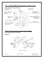
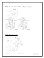
SUPPLEMENTARY / CENTRAL
WOODBURNING FURNACE MODEL 621
DAKA Corporation • 955 Industrial St NE • Pine City, Minnesota • 55063
Phone (320) 629-6737 • Fax (320) 629-3677 • www.dakacorp.com
INSTALLATION AND OPERATION INSTRUCTION MANUAL
NOTE:
This model has been tested and listed in accordance with Underwriters
Laboratories standard UL 391-2010 for Solid Fuel Central and
Supplementary Furnaces by Warnock Hersey International, Inc.
ICBO Report No. TL116; NER Qa219.
PRINCIPLE OF OPERATION:
This furnace model is designed for conventional up flow residential central forced air
heating systems, to be installed in either of the following ways:
1.
Supplementary "Add-On” Furnace Application (See FIG. 1)
As a supplementary furnace, this model is connected in parallel to a conventional
primary furnace system, using present ductwork to distribute wood-heated air
throughout the home. As long as the heat produced by the supplementary furnace
keeps the living area temperature above the setting on the primary furnace wall
thermostat, the primary furnace should not burn any gas, oil or use any electricity
beyond that required to run the primary distribution blower. Should the wood fire
fail to provide sufficient heat, however, the primary furnace will begin operating as
usual.
2.
Central Furnace Application (See FIG. 2)
This furnace also may be used as a freestanding central furnace, with its own
plenums and ductwork. The 550-cfm blower provided with this furnace is often
sufficient to provide air distribution for average size homes with relatively normal
size duct runs. NOTE: A second single No. 273 550-cfm blower can be added to
the back of the DAKA 621 to increase airflow or a No. 218 1580-cfm side mounted
blower may be required for larger homes with longer ductwork. Call 1-800-8843252 to order. As wood burning requires periodic attention, use of this unit as a
central furnace is somewhat inconvenient and requires a second heating system
(electric baseboard, vented gas room heaters, etc.) to act as a backup.
Page 1 of 15
DAKA Furnace Model 621
November 2009 Edition
Revision 1: June 2011
CAUTIONARY NOTES:
1. This furnace is designed for use only in conventional up flow systems and must
deliver heated air to a supply (warm air) plenum – never to ductwork. The warm
air supply from this furnace must never be connected to the cold-air return inlet of
a central primary furnace, as a possibility exists of components of the central
furnace overheating and causing the central furnace to operate other than as
intended.
2. Installation of this unit must be performed by a qualified installer familiar with
solid-fuel systems.
3. This furnace must be connected to a minimum 6" listed Type HT (high
temperature) appliance type chimney or a code-complying tile-lined
masonry chimney. Connection to a chimney flue serving another appliance
is prohibited.
4. A barometric regulator/damper may be used in the chimney connector (smoke
pipe leading to chimney flue) and must be set to maintain no more than .06"
water column updraft (DAKA barometric regulator #283 with adjustable settings
available at extra cost.)
5. Installation of this furnace in mobile homes or garages is prohibited.
6. This furnace must be installed on a non-combustible floor surface such as
concrete or 3/8" asbestos millboard. This surface must extend at least 16" in front
and 8" to side of DAKA furnace, under the chimney connector and at least 2" to
each side of connector. Clearances to combustible surfaces are:
To side wall:
To back wall:
To front wall:
18"
32½”
48"
Flue to back wall:
Flue to side wall:
23"
27"
See FIG. 3 for ductwork clearances and FIG. 4 for wall clearances. For more
information, including instructions for installations requiring reduced clearances,
please write for publication 211 from National Fire Protection Assn., Inc.,
Publications Dept., 1 Battery Park, Quincy MA 02169-7471 or visit their website
at www.nfpa.org.
7. Check local building and mechanical codes prior to installation to insure
conformance with all requirements. Review home insurance policy for coverage.
8. Chimney connector must be of minimum 24-ga. pipe with each section joined with
three sheet metal screws, with all fissures sealed with furnace cement. Do not
use galvanized pipe as the coating could melt and cause toxic fumes.
Page 2 of 15
DAKA Furnace Model 621
November 2009 Edition
Revision 1: June 2011
9. This furnace has been designed to operate with a maximum warm air duct
pressure of 0.2" water column and a maximum warm air duct temperature of
200°F. When used in a supplementary "add-on" mode, check the nameplate on
the primary furnace to determine compatibility.
10. When any supplementary furnace is connected in parallel to an existing primary
central furnace, a back-draft damper must be installed in the plenum of the
primary furnace below the warm air inlet from the supplementary furnace to
prevent the primary furnace from operating in an unintended manner. See FIG. 1
for an illustration of the position of this damper.
DANGER – RISK OF FIRE OR EXPLOSION! DO NOT BURN GARBAGE,
GASOLINE, DRAIN OIL OR OTHER FLAMMABLE LIQUIDS.
WARNING – RISK OF FIRE! DO NOT OPERATE WITH FLUE DRAFT EXCEEDING
.06" WATER COLUMN. DO NOT OPERATE WITH FUEL LOADING OR
ASH REMOVAL DOORS OPEN. DO NOT STORE FUEL OR OTHER
COMBUSTIBLE MATERIAL WITHIN MARKED INSTALLATION
CLEARANCES. INSPECT AND CLEAN FLUES AND CHIMNEY
REGULARLY.
CAUTION – HOT SURFACES! KEEP CHILDREN AWAY. DO NOT TOUCH DURING
OPERATION. MAXIMUM DRAFT MARKED ON NAMEPLATE.
Disposal of Ashes
Ashes should be placed in a metal container with a tight-fitting lid. The closed container
of ashes should be placed on a non-combustible floor or on the ground, well away from
all combustible materials, pending final disposal. If the ashes are disposed of by burial
in the soil or otherwise locally dispersed, they should be retained in the closed container
until all cinders have thoroughly cooled.
Creosote – Formation and Need for Removal
When wood is burned slowly, it produces tar and other organic vapors, which combine
with expelled moisture to form creosote. The creosote vapors condense in the relatively
cool chimney flue of a slow-burning fire. As a result, creosote residue accumulates on
the flue lining. When ignited this creosote makes an extremely hot fire.
The chimney connector and chimney should be inspected at least twice monthly during
the heating season to determine if a creosote buildup has occurred. If creosote has
accumulated it should be removed to reduce the risk of a chimney fire. Use of a smoke
vent thermometer to monitor stack temperature is recommended.
Page 3 of 15
DAKA Furnace Model 621
November 2009 Edition
Revision 1: June 2011
INSTALLATION INSTRUCTIONS:
I. UNPACKING
Remove all component parts from firebox for assembly; check piece count against
parts list on page 14 of this manual. NOTE: Remove firebrick from carton while
still within firebox. Do NOT attempt to lift full carton.)
Parts shortage:
If carton was sealed when purchased, call or write factory
immediately. Provide model number and serial number of
furnace, found on front mounted data plate, along with a
description and quantity of missing parts. Replacements will
be shipped. If carton was purchased unsealed, contact store
for missing parts.
Concealed Damage: If any components have been damaged in transit, advise the
dealer from whom the furnace was purchased of the nature
of the problem, so that a freight claim can be filed.
II. FURNACE ASSEMBLY (Refer to Parts List on page 14)
A. Attach fire door (1) to hinge bracket using hinge pin. IMPORTANT: Refer to
Instructions in Hinge Assembly Bolt Bag for proper installation. Note that door
features a double latch operation to limit initial swing of door to 1" on opening.
Continue turning handle clockwise beyond 3 o'clock position to permit full opening
of door. Close door with handle in same position; rotate counterclockwise to lock.
B. Insert thermal gasket (6) between ash door (5) and ash pan (7) front, and
assemble using two 1/4" bolts and nuts provided.
C. Insert Smoke Bypass Damper rod (8) through small hole above fire door, handle
pointing up, and run rod directly back onto smoke baffle plate inside firebox.
Reaching in through fire door opening, screw one large nut onto threaded rod all
the way to the end of the thread. Insert threaded rod end into the hole on the
upright plate on the Smoke Bypass Damper sliding plate, keeping the spring
handle upright. Screw on the 2nd large nut and tighten fully.
D. Remove cast-iron grate (10) from firebox. Proceed to install firebricks (15) along
sides and back of firebox, starting at the front, by slipping brick under retaining
angle iron and standing them upright on the grate support rails.
CAUTION: FIREBRICK MUST BE INSTALLED CORRECTLY OR
HEAT DAMAGE MAY OCCUR.
E. Reinstall cast-iron grate in firebox, reinforcing ribs down, resting on side rails.
Insert 3" x 13½" x ¼” steel grate spacer (11) at rear of grate.
F. Install 550-cfm blower (14) on back of furnace using four No. 12 x ½" screws
provided.
G. Furnace is shipped with air jacket already fitted and installed. If it has worked loose
during shipping or unpacking, do the following:
Page 4 of 15
DAKA Furnace Model 621
November 2009 Edition
Revision 1: June 2011
1. Remove air jacket top (15) by lifting up from front to back only, not side to side.
2. Ensure that bottom air jacket panel (16) is fully seated between lower bottom
support angles.
3. Ensure that channels welded on air jacket sides (17) engage the lower support
channels, and that the side panels are pressed tightly onto furnace around the
front and back corners.
4. Reinstall the air jacket top from back to front, making sure that all top edges of
each of the air jacket sides are inside of top.
5. Install Swing Plate (19) on hooks inside combustion chamber above Fire door
opening, with bent edge inward.
IV. WIRING INSTRUCTIONS – See FIG. 6 for Wiring Schematic
NOTE: For power supply connections, use No. 14 AWG or larger wires
acceptable for at least 105°C. Shut Off All Power While Installing.
A. Attach approved conduit carrying 3-wire 120V AC 15 amp service to any unused
knockout hole on J-box ring with conduit connector (not included for field wiring
connections).
B. Make all wiring connections per the schematic in FIG. 6, making all connections
shown with wire nuts provided. Check all wiring connections for tightness and
electrical safety.
C. Tuck all wires into J-Box Ring, install J-Box cover. Reinstall cover plate on blower
junction box.
V. CONNECTIONS TO DUCTWORK
A. For Use As A Supplementary "Add-on" Furnace – See FIG. 1
NOTE: SUPPLY PLENUM MUST BE METAL! A back draft damper must be
installed in the warm-air supply plenum of the primary furnace below the
point where the warm air ductwork connection from the DAKA furnace
enters the plenum. Actual design and installation procedure for such a
back draft damper is left to the installer, due to the large number of plenum
configurations involved. See FIG. 1 & FIG. 5 for illustration of placement.
1.
Mark and cut out two 8" round holes in the side of the supply (warm air) plenum
of the primary furnace.
IMPORTANT: Verify beforehand that sufficient clearance is available above
air conditioner coils, etc. If sufficient clearance is not available, air
conditioner coil may have to be moved to a second plenum with diversion
baffles for summer use.
Page 5 of 15
DAKA Furnace Model 621
November 2009 Edition
Revision 1: June 2011
2.
Attach each 90° sheet metal elbow to one end of straight 8" pipe. Insert elbow
into supply plenum of primary furnace with outlet pointing upward. Slip collar
over straight end of 8" pipe and push up tight against supply plenum for a good
air seal. See FIG. 1 & FIG. 5.
IMPORTANT: The 90° elbows within the supply plenum forms a venturi to
extract air from DAKA furnace when primary furnace blower comes on. An
absence of these elbows will cause backpressure down the warm air pipe to
the DAKA furnace, adversely affecting heat distribution, and possibly
damaging the DAKA furnace. If space prohibits installation of 90° elbow as
recommended, see FIG. 5 for alternate designs.
3.
Connect cold air return of primary furnace to DAKA filter box using a minimum 10”
diameter pipe.
NOTE: After attaching warm and cold air supply and return pipes to
primary furnace, check entire system to insure that static pressure remains
unaffected. Verify horizontal duct clearances (see FIG. 3).
B. For Use As A Central Furnace – See FIG. 2
1. Install a minimum 16" x 16" plenum (PLENUM MUST BE METAL) on air jacket
top with tin snips or sabre saw as needed, using starting collar to attach.
2. Install ductwork with proper clearances to combustibles in accordance with local
building codes.
3. Make sure to connect a cold air return line to the blower that was supplied with
your new DAKA Model 621.
VI. CONNECTING DAKA FURNACE TO CHIMNEY
Mount and secure 6" non-galvanized smoke pipe, 24-ga. or heavier, to rear
smoke outlet on DAKA furnace. Continue same gauge single-wall pipe to
chimney connection, with following safety rules in mind:
1. A barometric regulator should be installed in smoke pipe at least 18" from
furnace, to permit adjustment of chimney draft to a maximum of .06" water
column draft. Barometric Regulator No. 283 with adjustable draft setting is
available through DAKA for this purpose.
2. Smoke pipe should maintain a minimum 18" clearance to all combustibles
and should never pass through walls or ceilings. Use proper thimbles for
those passages.
3. Heat reclaimers, fins or the like should not be used on smoke pipe, as they tend
to cool flue gases and add to creosote formation on stoves and furnaces of
advanced airtight design.
4. All joints of chimney connector pipe should be secured with a minimum of three No.
7 sheet metal screws & further sealed with furnace cement to maintain good draft.
Page 6 of 15
DAKA Furnace Model 621
November 2009 Edition
Revision 1: June 2011
5. Smoke pipe should normally be installed with male ends leading from chimney to
furnace; should runny creosote be formed in chimney connector, it will then return
through pipe to furnace without dripping out of joints.
6. Maintain a minimum of 1/4" per foot of pipe rise to chimney connection; the
steeper the rise, the more easily draft will be maintained, generally.
7. Avoid the use of 90° elbows in any chimney connector, as they adversely
affect draft. If 90° elbows must be used, do not install more than two in any
chimney connector.
8. Adequate combustion air must be provided in furnace area to prevent poor firing
and smoking. Keep a window cracked open in furnace area or install dryer-type
4" vent to bring in fresh air.
VII. OPERATING CONTROLS
IMPORTANT: In a supplementary "Add-On" installation, the blower on the
DAKA furnace can be used as a circulation blower for heating the house.
The blower can be used in conjunction with your primary furnace blower to
boost air circulation in large ductwork systems. An optional fan control may
need to be located in supply plenum to turn primary blower on and off when
heat is received from the DAKA furnace. See FIG. 1 for fan control location.
IMPORTANT: Normal operation will produce flue gas temperatures in the
300°- 600°F range. If higher or lower operating temperatures are normally
obtained, increase or decrease the barometric draft control setting and room
thermostat setting to bring temperatures to within range. Too cool a flue gas
temperature can result in heavy creosote formation, while too hot a
temperature increases danger of chimney fire.
A. Smoke Bypass Damper
Due to the extra long smoke baffle in this model, designed to create the longest
possible flame path for maximum heat extraction, a sliding smoke bypass damper
plate, controlled by the damper rod over the fire door has been provided. Before
opening fire door for reloading or checking fire, pull the damper rod out fully to allow
the smoke to exit at rear of chamber, rather than rolling forward and possibly spilling
into the room. After closing fire door, push damper rod fully in to seal rear vent.
VIII. EMERGENCY OPERATION INSTRUCTIONS
A. Operation During Power Failure
1. Remove furnace filter(s) to prevent fire hazard.
2. Set automatic draft control to no higher than “EPF” (Electrical Power Failure).
3. Continue firing the fire with smaller loads, more frequently tended.
4. Use extreme care and vigilance during power failure to keep furnace from
Page 7 of 15
DAKA Furnace Model 621
November 2009 Edition
Revision 1: June 2011
overheating, which could cause severe warpage or breakage.
5. The air jacket top and side may be removed to provide more radiant heat to
help cool the firebox.
CAUTION: DO NOT expect the DAKA furnace to keep the house as warm
during a power failure as when power is on. Do no attempt to
increase heat output by opening ash door or fire door.
B. In Case of a Chimney Fire:
1. Call the fire department immediately.
2. Reduce room thermostat to lowest point to shut off auto dampler. Use
chimney fire extinguishing flares if you have them. (Available at your local
home store or fireplace and woodstove shops).
3. After chimney fire, do not attempt to use chimney again until a professional
inspection is made to determine safety.
Page 8 of 15
DAKA Furnace Model 621
November 2009 Edition
Revision 1: June 2011
IX. MAINTENANCE OF YOUR DAKA FURNACE
A. Fueling Procedure
Fill with cordwood (and/or coal, if applicable) to the top of the firebrick. Before
burning coal, you must have a coal burning grate and a fire door equipped with a
spin draft (available from dealer or direct from the factory).
B. Flue Pipe and Chimney
These must be checked frequently during heating season, and deposits of soot
and creosote over 1/8" thick removed using stiff-wired brushes designed for the
job. Professional cleaning by a chimney sweep at least once a season is highly
recommended.
C. DAKA Furnace Blower
The rear blower on your new DAKA Furnace Model 621 has permanently
lubricated bearings. Re-lubrication is NOT required. Vacuum away dust and dirt
on motor air inlets and also on blower impellers at least once each season.
CAUTION: TURN OFF ALL POWER TO UNIT BEFORE CLEANING AND
LUBRICATION.
D. Fire Chamber and Ash Pan
Check ash pan every few days and safely dispose of ashes. Keep ashes from
building up on grate and interfering with combustion airflow from below. At end of
heating season, clean out all residual ashes from furnace. The moisture they
contain could rust your furnace over the summer months, thereby shortening the
life of the unit.
X. TROUBLE SHOOTING
A. Problem: Smoke puff back when loading, poor burning, insufficient heat
Solutions:
1. Insufficient draft--debris or creosote could be blocking flue; inadequate chimney
height or design could be causing downdrafts; check chimney connector for air
leaks and seal with furnace cement; adjust barometric regulator to higher setting.
2. Insufficient make-up air-- the house could be so well insulated that infiltration air
is not getting in to replace air used in combustion; open a window slightly in
furnace room or install a vent to the outside in furnace area.
B. Problem: Poor heat throughout house while burning wood
Solutions:
1. Poor quality wood--burn only wood which has been air-dried for at least six
months, preferably a year or more. Use hardwoods such as hickory, oak, maple,
etc. for highest heat value per load.
2. Check to insure that all cold air return vents are open and not blocked with
furniture, etc.
3. Make sure that all duct joints are airtight, and apply duct tape to seal.
4. Check flue gas temperature--normal operating range is 300º-600ºF. Lower
temperature would indicate insufficient draft or inadequate combustion air.
5. Insure that primary furnace blower is turning on to distribute heat effectively.
Lower "FAN ON" setting on primary furnace fan control to start circulation earlier.
Page 9 of 15
DAKA Furnace Model 621
November 2009 Edition
Revision 1: June 2011
C. Problem: Paint Discoloration (whitish appearance)
Solution:
Paint is rated for 900°F surfaces, and overheating of furnace will cause a whitish
appearance on outside of combustion chamber surfaces; reduce chimney draft to
control overheating. NOTE: To cover discoloration, obtain a high-temperature flat
black spray paint from hardware or fireplace shop.
If problems persist, or help is needed in installation or operating of furnace,
contact:
Customer Service Department
DAKA Corporation
955 Industrial St. N.E.
Pine City, MN 55063
(320) 629-6737
Page 10 of 15
DAKA Furnace Model 621
November 2009 Edition
Revision 1: June 2011
FIG. 1 – Typical Installation As Supplementary “Add-On” Furnace
NOTE: Supply plenum must be metal.
Primary Furnace
Warm Air Plenum
EXAMPLE
6” Minimum Listed Type HT
Chimney serving DAKA
Furnace Only
Cold Air
Return
90° Elbows installed
inside plenum
(See FIG. 5 for alternatives)
Location of Fixed
Back Draft Damper to
be installed on
Primary Furnace
Twin 8” round
warm air outlet
pipes
Barometric Regulator
Primary Furnace
(natural gas, electric, oil)
Minimum 12” Round Cold
Air Return Pipe Connected
To Filter Box Inlet
FIG. 2 – Typical Independent Central Furnace Installation
NOTE: Supply plenum must be metal.
EXAMPLE
Page 11 of 15
DAKA Furnace Model 621
November 2009 Edition
Revision 1: June 2011
FIG. 3 – Clearances from Horizontal Warm Air Ducts
From Sides and Top of Warm Air Plenum – 6”
From Horizontal Ducts within 6 Ft. of Plenum – 6”
From Horizontal Ducts beyond 6 Ft. of Plenum – 0”
FIG. 4 – Clearances to Combustibles & Flooring
Wall Clearances to Combustibles:
Furnace to sidewall: 18”
Flue to sidewall: 27”
Furnace to back wall: 32 ½”
Flue to back wall: 23”
Furnace to front wall: 48”
FIG. 4A
FIG. 4B
Dimensions shown are minimum
distances to stay clear from
combustible walls.
Dimensions shown are minimum
clear distances for floor protector or
non-combustible floor.
621
621
Page 12 of 15
DAKA Furnace Model 621
November 2009 Edition
Revision 1: June 2011
FIG. 5 – Alternative Warm Air Plenum Pipe Insert Designs
FIG. 6 – Wiring Schematic
Page 13 of 15
DAKA Furnace Model 621
November 2009 Edition
Revision 1: June 2011
4
7
KEY
No. Part Description
1.
2.
3.
4.
5.
6.
7.
8.
9.
10.
11.
12.
13.
14.
15.
16.
17.
18.
19.
20.
21.
22.
23.
Fire Door Assembly
Fire Door Gasket
Junction Box Assembly - 4x4 (A)
Number not used
Snap Disc Fan Control (B)
Ash Door Assembly
Thermal Gasket - Ash Door (A)
Ash Pan Assembly
Bypass Damper Rod & Plate
Number not used
Cast Iron Grate
Grate Spacer (A)
Firebrick
Hinge Assembly (A)
Bolt Bag (B)
Blower - 550 cfm
Air Jacket - Top Panel
Air Jacket - Bottom Panel
Air Jacket - Side Panel
Number not used
Swing Plate (A)
Number not used
Number not used
Number not used
Auto Damper Assembly
Flexible Conduit w/wires (A)
Wire Set [inside conduit] (A)
Wire Nut (B)
Sheet Metal Screw #12 x ½” (B)
Crimp. Term. ¼” Female 14 ga. (B)
Conduit Connector – Straight (B)
Conduit Connector 90° (B)
Hex Bolt, ¼ x ¾ for ash pan door (B)
Hex Nut, ¼ for ash pan door
Part No.
Qty
34200
57610204
33100
-58640000
35100
57610202
35400
57590214
59650001
57660001
57600001
30720
36212
63610004
64590210
64590208
64590209
57590211
32200
62630407
60670006
62630802
61660208
62670205
62670201
62670202
H1434
HN14
1
1
1
1
1
1
1
1
1
15
1
1
1
1
2
1
1
2
1
4
14
2
2 (01)
or 1 ea
2
2
A = Large Parts Bag #36205
B = Small Parts Bag #36210
All other parts are separate components
Page 14 of 15
DAKA Furnace Model 621
November 2009 Edition
Revision 1: June 2011
LIMITED WARRANTY
DAKA Corporation warrants the combustion chambers of its supplementary
furnaces to be free of defects in material or workmanship for five years from date of
sale; all other components, including electronics, gaskets and grates are covered in
the same manner for a period of one year.
DAKA will repair or replace defective components, at our option, at no charge for
parts and labor, and will pay freight charge for one-way shipment for warranty
claims during first year. In second and subsequent years, only parts and labor will
be provided at no charge. DAKA is not responsible for installation or dismantling
costs.
Warranty void if unit is used in other than residential service connected to
conventional basement-type up flow central heating system, if non-approved fuels
are used in firing of units, or if unit is damaged due to accident, improper
installation or negligence.
For service under this warranty, contact selling dealer or DAKA Corporation,
Customer Service Dept., 955 Industrial St NE, Pine City MN 55063; Telephone
(320) 629-6737.
Implied Warranties including that of merchantability are expressly limited in
duration to the duration of this warranty. DAKA Corporation disclaims any
responsibility for consequential damages. Some states do not allow limitations on
how long an implied warranty lasts, or the exclusion or limitation of incidental or
consequential damages, so this limitation and exclusion may not apply to you.
This warranty gives you specific legal rights, and you may also have other rights
which vary from state to state.
This is our exclusive written warranty.
Page 15 of 15
DAKA Furnace Model 621
November 2009 Edition
Revision 1: June 2011