1
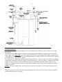
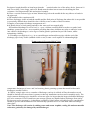
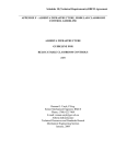
HEATWELL
Mains Pressure Hot Water Specialists
Installation & User
Instructions for
Combination Boiler
Models
215 DSS/12Kw
215DSS/15Kw
To be left with
The Householder beside
the boiler for future
reference
After Commissioning
System
Parts supplied: - 1 – Combination Boiler
1 – 18Ltr Expansion Vessel
1 - 8Ltr Expansion Vessel
+ Fixing Brackets
Central Heating Expansion, Charging Kit
2 Stainless Steel Braided Connectors
Installer Owners Instruction Manuel
2
Index
Page
Manufacturer and Installer Information
2
Site preparation and Requirements
3
Plumbing Layout and Installing
4
Special Instructions for Installing Tundish
5/6/7
Pressure Relief Valve
7
Electric Power supply Connections
8
Boiler Electric Control Panel
9
Commissioning - Filling Boiler
10
System Control and Economy Measures
11
Boiler Specification
12
Manufacturers Guarantee
13
User instructions
14
Fault Correction
15
Maintenance
15
Hydro Electric – Total Control Tariff
16
Boiler front view
17
-------------------------------------------
Manufacturer
Electric Central Heating Company Ltd
Emtex House, Benneworth Close,
Hucknall, Nottingham NG15 6EL Tel 0115 968 1273
-------------------------------------------
Installed by :-
Name_______________________________________________
Address_____________________________________________
Tel No______________________________________________
Completion Date______________________________________
WARRANTY CARD MUST BE RETURNED
3
INSTALLATION
INSTRUCTIONS
SITE PREPARATION
Site requirements
When an Installation is contemplated the application for supply should be made in good time to the
local Electricity Supply Company stating the boiler make and model as shown on the boiler specification
label to ensure that sufficient power is available from the mains.
All installations must comply with the relevant building and electricity regulations and water bye-laws.
These boilers being un-vented, must be installed by a “competent person” as defined by section G3 of the
current building regulations. The local authority must also be informed of the installation.
To ensure correct installation and economic trouble free operation, ensure that only an approved installer is
used who is in possession of the relevant pressure water certificate. Contact one of the Heatwell technical
help lines at :- Nottingham 0115 968 1273 or Glasgow 0141 944 0440
This electric combination boiler is designed to make use of all the wet electric tariffs currently available.
This in most cases will consist of interruptions or restriction of the boiler power supply which the boiler
has been designed to cope with. In return the cost of the electricity supply will be less expensive than the
domestic rate. Application must be made for an additional supply before any installation work is started.
As the boiler is un-vented, the mains water supply pressure and flow rate should be checked to ensure a
minimum supply pressure of 1.5Bar is available. If the water supply pressure can not be relied on, then a
vented system can be considered. Heatwell should be contacted for assistance with the planning of the
vented installation so that the maker's guarantee remains intact.
If the boiler is used in an area where the temporary hardness exceeds 200ppm, to comply with warranty, an
approved scale inhibitor must be fitted to the cold water supply of the boiler.
Location
The electric combination boiler should be located in a space where the surface is flat, level and capable of
supporting the weight of the boiler when full of water. (see page 12 for boiler weights)
The boiler should not be subjected to extremes in temperature (outbuildings) unless frost protection is
provided, or, (internal cupboards) No special ventilation need be provided, but the boiler should not be
covered with clothes or anything that would prevent the escape of heat from the front panel, or the
operation of safety valves.
Clearances are not critical except that the boiler should be positioned to allow access to the heating
elements and control box on the front of the boiler.
In addition, sufficient clearance should be allowed to enable access to the expansion vessels, valves and
circulating pump as may be required by an engineer servicing or replacing these items. The central heating
pressure Gauge and Tundish should be positioned so that they are easily visible and accessible.
Care should be taken to allow space for insulation of all pipe-work, including cold pipes which will
conduct heat within the boiler cupboard; this pipe insulation should be 25mm thick to prevent heat-loss
from the storage boiler. This is important to reduce running cost.
Plumbing Layout
4
Installing the Boiler
Keep the Boiler stored in its packaging in a dry area until ready to install. It can be easily moved with a
sack barrow
The Boiler is delivered with all valves and necessary piping fitted, all that is required is a 22mm mains
water supply with a stop valve, and a line strainer/filter fitted. A circulating pump should be supplied and
fitted to the C/H return pipe. A drain valve should be fitted to enable the boiler to be drained either through
a suitable hose or a fitted pipe to a drain.
The diagram above shows the plumbing connections to the boiler, which consist of the mains water supply
(22mm pipe), Domestic Hot Water supply from the Mixing valve (pre-set at 55deg C), balanced cold water
supply for mixer shower Central Heating flow and return pipes and expansion vessels as shown in the
diagram. All fittings must be checked for leak tightness along with the factory fitted controls. No special
tools are required.
NOTE The central heating flow & return pipes are turned downward to avoid a thermal siphon (gravity
feed).
The two expansion vessels (central heating and domestic hot water) need to be fitted, using the supplied
wall brackets (as shown on page 4).
5
Top of Boiler Showing Factory fitted Valves
The discharge pipe work from the tundish, shall fall continuously throughout its length. Pipe runs must
not exceed 9m in length or equivalent resistance with bends. A 15mm pipe from the tundish is made
available for connection to the C/H pressure relief valve (see page 7).A full description regarding the
regulations for installing the tundish is provided on page 6.
Draining System The boiler can be drained by the valve at the bottom of the tank, a sink hot tap should be
opened to allow air into the system.
WARNING
The outlets for the T&P relief valve and expansion relief valve must not be used for any other purpose. No
other valve may be fitted between the expansion valve or the temperature and pressure relief valve and the
storage boiler.
Take great care not to allow debris or jointing tape to get into the system as this could impair the operation
of the safety valves.
Tundish worked example
The example below is for a G1/2 temperature relief valve with a discharge pipe (D2) having 4No
elbows and a length of 7m from the tundish to the point of discharge Tundish
Special attention must be paid to the Tundish to comply with G3 regulations, a copy of which
is shown below.
Sizing of copper discharge pipe for common temperature relief valve outlet sizes table 1
6
Resistance
created by
each elbow or
bend
G 1/2
22mm
Up to 9m
0.8m
28mm
Up to 18m
1.0m
35mm
Up to 27m
1.4m
G 3/4
22mm
28mm
Up to 9m
1.0m
35mm
Up to18m
1.4m
42mm
Up to 27m
1.7m
G1
28mm
35mm
Up to 9m
1.4m
42mm
Up to 18m
1.7m
54mm
Up to 27m
2.3m
From table 1 Maximum resistance allowed for a straight length of 22mm copper discharge pipe (D2) from
a G1/2 temperature relief valve is :- 9.0m
Subtract the resistance for 4 No 22mm elbows at 0.8m each = 3.2m
Therefore the maximum permitted length equates to 5.8m
5.8 is less than the actual length of 7m therefore calculate the next largest size
Maximum resistance allowed for a straight length of 28mm pipe (D2) from a G1/2 temperature relief valve
equates to 13m
Subtract the resistance for 4 No 28mm elbows at 1m each = 4m
Therefore the maximum permitted length equates to 9m
i.e.. the actual length is 7m. A 28mm (D2) copper pipe will be satisfactory
Diagram 1. Typical discharge pipe arrangement
Valve
outlet size
Minimum
size of
discharge
pipe D1*
15mm
Minimum size of
discharge pipe D2*
from Tundish
Maximum resistance
allowed expressed as a length of
Straight pipe (no elbows or bends)
3.9 The discharge pipe (D1) from the vessel up to and including the tundish is generally supplied by the
manufacturer of the hot water storage system (see paragraph 3.5). Where otherwise, the installation should
include the discharge pipe(s) (D1) from the safety device(s) in either case the tundish should be vertical,
located in the same space as the invented hot water storage system and be fitted as close possible and
within 500mm of the safety device e.g.. the temperature relief valve.
The discharge pipe D2 from the tundish should terminate in a safe place where there is no risk to persons
in the vicinity of the discharge, be of metal and :a/ be at least one pipe size larger than the nominal outlet size of the safety device unless its total equivalent
hydraulic resistance exceeds that of a straight pipe 9m long i.e..discharge pipes between 9m and 18m
equivalent.
7
Resistance length should be at least larger than the
nominal outlet size of the safety device, between 18
and 27m at least 3 sizes larger, and so on. Bends must be taken into account in calculating the flow
resistance. See Diagram and Table and worked example.
b/ Have a vertical section of pipe at least 300mm long, below the tundish before any elbows or bends in
the pipework.
c/ Be installed with a continuous fall.
d/ Have discharges visible at both the tundish and the final point of discharge but where this is not possible
or practically difficult there should be clear visibility at one or other of these locations.
Examples of acceptance discharge arrangements are:d.1/ Ideally below a fixed grating and above the water seal in a trapped gully.
2/ Downward discharges at a low level i.e.. up to a 100mm external surfaces such as car parks, hard
standings, grassed areas etc., are acceptable providing that where children may play or otherwise come
into contact with discharges, a wire cage or similar guard is positioned to prevent contact, whilst
maintaining visibility.
3./ Discharges at a high level; e.g.. in to a metal hopper and metal down pipe with the end of the
discharge pipe clearly visible (tundish visible or not) or onto a roof capable of withstanding high
Temperature & Pressure Relief Valve
temperature discharges of water and 3m from any plastic guttering systems that would collect such
discharges (tundish visible).
4./ Where a single pipe serves a number of discharges, such as in a block of flats, the number served
should be limited to not more than 6 systems so that any installation can be traced reasonably easily. The
single common discharge pipe should be at least one pipe size larger than the largest individual discharge
pipe to be connected. If un-vented hot water storage systems are installed where discharges from safety
devices may not be apparent i.e. in dwellings occupied by blind, infirm or disabled people, consideration
should be given to the installation of an electronically operated device to warn them when a discharge
takes place.
Note: The discharge will consist of scalding water and steam. Asphalt, roofing felt and non-metallic
rainwater goods may be damaged by such discharges.
8
ELECTRICAL CONNECTIONS
The electrical installation must be carried out by a qualified electrician to the current IEE wiring
regulations (BS 7671)
Wiring consists of a switch fuse or magnetic circuit breaker of 63 amp rating adjacent to the supply
companies meter. 25mm2 colour coded tails should be provided to allow the electricity supplier to make
the connection to the meter.
The boiler supply cable should comply with the current IEE regulations with regard to length; load carried
and should be run from the switch fuse or MCB to an isolator with two pole disconnection and a minimum
contact separation of 3mm, adjacent to the boiler.
From the local isolator to the boiler a cable should be run in conduit, the same size as was used to bring the
supply from the switch fuse or MCB.
WARNING:- THIS APPLIANCE MUST BE EARTHED, & FITTED WITH AN EARTH
LEAKAGE CIRCUIT BREAKER.
Wiring of the circulating pump, programmer/room thermostat must be wired on the 24hr supply (no
connection to the boiler) and follows normal domestic practice. The relevant manufacturer instructions
should be adhered to.
Diagram 3 Schematic Diagram of Boiler Power Supply (Single Supply)
9
Boiler Control and Mains power Connections
Commissioning
Commissioning can only be carried out when the electrical and plumbing work is completed including the
electric metering.
10
Filling the Domestic Hot Water & Heating System
The Domestic Hot Water can be filled by opening one of the hot water taps in the house to allow the air in
the boiler to escape and then the mains valve opened to allow water into the boiler. The 3Bar boiler
pressure will be controlled by the pressure reduction valve. The central heating system should be filled by
connecting the filling loop to the water mains and the valves turned on. The heating system will fill and
when the system is bled at the radiators, the proper pressure should be set at 1.5Bar... After the initial
filling the boiler and the radiator system should be flushed and drained, The domestic hot water side can
be flushed by opening the drain valve at the bottom of the tank and letting the water flow until flushing is
complete. The central heating system can be flushed by connecting the filling loop and allowing water to
flow through the system until flushing is complete. Any leaks apparent should be attended to. A suitable
inhibitor should be added with the filling loop disconnected, by filling the required amount of inhibitor
through the 15mm pipe stub provided for the auto air vent on the flow side of the central heating system on
top of the boiler. The heating system can then be filled to its proper pressure of 1.5Bar, the pump should
be run for some time to expel all the air from the system including bleeding the radiators. Finally the
radiators should be balanced and the pump set to the lowest speed that will suffice in supplying full heat to
all the radiators. It will probably be necessary to return to the house and bleed and refill the system to its
proper pressure after the system has been running due to the automatic bleeder reducing the pressure as it
removes air from the system during the settling in period.
. The filling loop should always be disconnected and both valves closed after filling is complete. It is also
important to check the output temperature from the Domestic Hot Water valve. Output temperature is
normally factory set at 55Deg C but can be adjusted to the house holders requirement by removing the
locked blue plastic cap by the centre Allen screw and resetting the valve. The system pressure should be
checked after a settling period of approx one month.
11
System Control and Economy Measures
Important
It is very important that since the boiler stores heat to avoid using peak rate power, all pipes in the vicinity
of the boiler and outside the heated areas in the house (i.e. under the floors and in the attic), should be
insulated with good quality insulation, minimum thickness of 25mm to prevent standing heat loss.
Failure to insulate can lead to very high electricity bills.
In addition care must be taken to avoid gravity feeding, hot water travelling upwards and heating radiators
upstairs with the pump off. This draws heat from the boiler when it is not required.
System Control
It is important for reasons of economy that there is proper control over the heating system. For this reason
it is recommended that the Danfoss TP5000, or similar programmer is used. This programmer is battery
operated and as such does not require a power supply, which means it will retain the set program in the
event of a power failure. It serves as a room thermostat and time clock combined, thus removing the need
to provide a by-pass radiator. This type of programmer also serves as a frost stat, which will bring the
heating on if the temperature in the house drops below 5deg C. Provided of course the boiler is switched
on.
It is recommended that the programmer is set up in the sitting room, in a position where it is not influenced
by heat from the radiators or sunlight. If the sitting room contains a solid fuel fire or any other form of
additional heating, then an alternative site must be considered such as the hall.
The radiators throughout the house should be fitted with thermostatic valves, except in the room where the
programmer is sited.
This would mean that the rooms would be controlled by the thermostatic valves and because they are
usually smaller, or require a lower temperature, the required heat will be achieved before the sitting room.
When the sitting room reaches temperature the pump is switched off, this removes the need for a by-pass
radiator wasting heat from a pump circulating heat round a house which has achieved temperature.
It should also be considered that the amount of water in the system is kept to a minimum by the use of low
capacity radiators. When the system is switched on all the cold water in the radiators and pipes has to be
reheated by the boiler and that has to be paid for!
______________________________________
12
Heatwell Electric Combination Storage Boiler
Specification
Total Requirement 12Kw Tariff 2000
Scottish Hydro Electric – 12Kw
Economy Tariffs
63 Amp / 230 Volts / Single Phase
63 Amps Split 60% - 40%
ScottishPower / Economy 2000
Scottish Hydro Electric / Total Control
Heating Elements –Top
Heating Element - Middle
Heating Element - Bottom
21/4”BSP 3kw coil type
21/4” BSP 2x3kw straight
21/4” BSP 3kw coil type
Note;
Standard emersion heaters
Should not be used
Heating (Maximum House Heatloss)
Domestic Hot Water
Heatwell 12 9kw or 40940 BTU’s
3kw All Boilers
Dimensions & Performance
Total Height / Width inc TPR/ Depth inc cover
Heatwell 12 – 1660mm / 660mm / 655mm
Weight Empty / Full Heatwell 12
Heating System
Pressure Relief Valve Setting
Expansion Vessel Pre-charge
Pressure / System Cold Pressure
Domestic Hot Water Store
100% Heat up Time
70% Re-heat Time
T&PR Valve Opening Temperature &
Pressure Relief Valve Setting
Pressure Reduction Valve
Expansion Vessel Capacity – Central Heating
Expansion Vessel Capacity – Domestic Water
Maximum temperature setting
Over Temperature Shut Down / Manual Reset
Available Domestic Hot Water Capacity
55Deg C *Heatwell 12
66Kg – 290Kg
3Bar
1.5Bar
1.5Bar
Heatwell 12 – 215Ltrs
15Deg C to 80Deg C - 5Hrs 29Min
4Hrs 42Min #
95Deg Celsius
6Bar
3Bar
8Ltrs *
18Ltrs *
85Deg C
90+/- 3 Deg C
68 Gallons / 309Ltrs
* Depending on Heating Load
*Note If a secondary circulation is used, then an extra expansion vessel is to be fitted to accommodate the
extra volume.
#Note If power is switched on from a cold boiler, then 25Ltrs of hot water at 40Deg C will be available
after 10 Minutes.
13
GUARANTEE
We the Electric Central Heating Company guarantee that should this electric combination boiler prove
to be defective by reason of faulty workmanship or material within 24 months of the date of purchase, we
will replace the defective parts free of charge on condition that :1.
The boiler has been correctly installed and used only on the supply circuit or voltage stamped on
the rating plate.
2.
The boiler has been used and serviced in accordance with these instructions and has not been
tampered with or otherwise subject to misuse, neglect or accident.
3.
The appliance has not been taken apart, modified or repaired by a person other than authorized by –
Electric Central Heating Company (Heatwell)Ltd
4.
Evidence of the date of purchase and annual maintenance checks in the form of an invoice, receipt
(or hire purchase documents) is required if service under guarantee is required. Any service under
guarantee will not alter the original expiry date at the end of the 24 month period
5.
Warranty registration card must be completed and returned to register your guarantee.
Failure to do so may result in a delay should any fault arise.
6.
Scale will build up in hard water areas with a boiler operating at high temperature such as this one.
We there for strongly recommend that scale inhibitors are fitted to protect the boiler. The
manufacturers guarantee does not extend to cover this natural phenomenon
In the event of any difficulties please contact Technical Services
Head Office & Manufacturer England Phone 0115 968 1273
Scotland Glasgow Office
Phone 0141 944 0440
Electric Central Heating Company (Heatwell)
Emtex House
Unit 51
Benneworth Close
42 Dalsetter Avenue
Hucknall
Glasgow G15 8TE
Nottingham NG15 6EL
Tel 0141 944 0440
Tel 0115 968 1273
Fax 0115 968 0464
email. [email protected]
web. www.heatwell.co.uk
14
USER INSTRUCTIONS
HEATWELL STORAGE COMBINATION BOILER
PRODUCT
Electric Combination Boiler Models - Heatwell Electro 12Kw
DESCRIPTION
The unvented electric combination boiler is an efficient boiler unit designed to provide you with central
heating and hot water.
Your electricity supplier controls the electricity supply to the boiler, avoiding the peak supply periods.
This enables you to receive low cost electricity, which the boiler due to its storage capacity will continue
to supply heat and hot water during the interrupt periods. It is however, advisable to program the heating to
prevent the house becoming cold i.e. below 18Deg C and have the heating programmed to raise the
temperature to comfort level 21DegC at least 30mins before a switch off period. This will assist the boiler
store of hot water to bridge the two hour gap when the power is switched off.
OPERATION
Central Heating
The electric combination boiler is designed to connect to a conventional domestic central heating radiator
system. Control of the heating is by a standard heating programmer, room thermostats and thermostatic
radiator valves, common to all wet central heating systems. Reference should be made to the makers
instructions supplied with this equipment.
Hot Water
Hot water is supplied from the boiler, through a mixing valve, located on the boiler hot water outlet pipe.
This valve is factory pre-set at 55Deg C and should not normally require adjustment. In the event that
adjustment is required, your approved installer, to ensure that there is no danger of high water
temperatures, which could cause scolding, must carry this adjustment out.
The boiler should at all times be left switched on to take advantage of the tariff. And since the heat loss
from the boiler is very low, the cost will be minimal.
Holiday Periods
The cost of leaving the boiler in the "on" position when away for a short break or holiday is extremely
small due to the low boiler heat loss and has the advantage of providing hot water and heat when
demanded on your return. During extended periods it is recommended that the boiler be switched off,
except in winter when there is the danger of frost damage the boiler should be left switched "on" with the
room thermostat set to 5deg C at least to provide frost protection.
15
Fault Correction
Carry out the following before calling out the installer or service engineer:-
Inadequate or no heating
Ensure that the power to the boiler is switched "on" at the mains switch beside the meter, and the isolator
beside the boiler. The flashing light on the tele meter will indicate the power consumption, this light will
not show if it is a "power off period". A red light should be visible through the aperture on the boiler front
cover. If the boiler power is switched "off" then "on", after a short delay the relays can be heard to click in
on the control panel at the front of the boiler. If the power supply is on and no light is visible on the boiler,
it is likely that a fault has shut the boiler power off. The installer or a service engineer will have to be
called to rectify the fault and restore the power supply.
Hot Water but no heat at the radiators
Check that the circulating pump is running or the programmer/thermostat/timer is asking for heat.
Water Discharging from the Tundish
(Visible drain connection on the side of the Boiler)
Switch off the main switch (beside meter) or the isolator switch (beside boiler)
If water still flows through tundish, turn off water supply to boiler.
Call installer.
-------------------------------------Maintenance
It is recommended that all electric combination boilers are serviced annually by the installer or his
approved agent.
It is also recommended that the concentration of the central heating protector be checked to ensure that the
boiler and radiator system are protected against corrosion.
In addition the following checks must be made:1. The correct operation of the expansion pressure relief valves. (central heating and hot water
systems)
2. The correct operation of the temperature and pressure relief valve fitted to the side of the boiler.
3. The operating pressure of the pressure reducing valve (3 bar) on the cold water supply. (clean the
water strainer if fitted)
4. Check the pre-charge pressure on the heating system (pressure gauge on the small expansion
vessel) If the pressure is low the system can be recharged by connecting the braided flexible hose
to the system and opening the valve till the pressure gauge reads 1.5 Bar. .(The pressure on the
gauge will increase as the system heats up).
5. Check the pre-charge pressure in the expansion vessels. (heating and hot water)1.5 Bar for
heating and 3Bar for the domestic hot water
6. Check all the fuses, and all cable connections to ensure the fuses are intact and there is no
evidence of overheating at the connections.
7. Check the input current to the boiler by reducing the temperature by running off some domestic
hot water or running the heating system to ensure that the boiler is drawing full power. This is best
achieved by using a clamp meter on the mains cable.
_______________________________
16
Electrical connections for Total Control Tariff
The electrical installation must be carried out by a qualified electrician to the current IEE wiring
regulations (BS 7671)
Wiring consists of switch fuses or magnetic circuit breakers of the appropriate current rating, adjacent to
the supply companies meter. Colour coded tales should be provided to allow the supply company to make
their connection to the meter.
The boiler supply cables should comply with the current IEE regulations with regard to length and load
carried. They should be run from the switch fuse or MCB to an isolator, with two pole isolation in both
circuits of a minimum contact separation of 3mm, to a location in adjacent to the boiler.
If the boiler is situated in the same space as the supply companies’ meter, then this isolator will not be
required.
From the local isolator cables should be run in conduit, the same size as was used to bring the supply from
the switch fuse or MCB.
Mains Connections For Total Control Tariff
Other than having the split supply to comply with the Total Control Tariff, the boiler is the same as the one
operating on Scottish Power’s Economy 2000 Tariff
______________________________________________
17
Heatwell Stainless Steel Electric Combination Boiler
With front Cover Removed to show location of Electrical Components
Warning There are live electrical components
Under the front cover