1
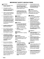
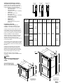
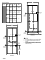
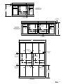
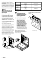
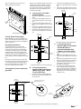
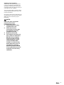
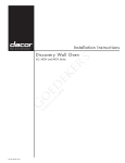
Installation Instructions Wall Oven read and save these instructions Tested in accordance with the latest edition of ANSI/UL 858 and can/csa-c22.2 no. 64 Standard for household electric cooking and liquid heating appliances. CONVENTIONS USED IN THESE INSTRUCTIONS WARNINGS: Must be followed carefully to avoid personal injury or damage. NOTES: Contain helpful hints and tips to facilitate the installation. IMPORTANT 1. 2. 3. 4. 5. Before beginning installation, please thoroughly read and become familiar with these instructions. Installation and service must be completed by a qualified installer or service agency. Installer: Please leave these Installation Instructions with the owner. Owner: Please keep these instructions for local electrical inspector’s use and for future reference. Read the accompanying Use & Care Manual prior to operating this appliance. TABLE OF CONTENTS STEP STEP STEP STEP STEP STEP STEP STEP STEP STEP STEP STEP 1 2 3 4 5 6 7 8 9 10 11 12 Package contents verification Installation planning Installing the support platform in the cabinet Electrical power supply requirements Removing the oven door(s) Turning of the power supply Electrical connection Mounting the oven Installing the exhaust deflector Re-installing the oven door(s) Installation check list Verifying oven operation Part No. 65433 Rev. C Page Page Page Page Page Page Page Page Page Page Page Page 2 2-4 5 5 5-6 6 6 7 7 7 7 8 IMPORTANT SAFETY INSTRUCTIONS WARNINGS: 1. Read all instructions before using the appliance. 2. This appliance must be grounded. Connect only to a properly grounded outlet. See “Grounding Instructions”. 3. Install or locate this appliance only in accordance with these installation instructions. 4. Use this appliance only for its intended use as described in this manual. Do not use corrosive chemicals or vapors in this appliance. This type of oven is specifically designed to heat and cook dry food. It is not designed for industrial or laboratory use. 5. As with any appliance, close supervision is necessary when used by children. 6.Do not install this appliance if it has a damaged electrical supply conduit, if it is not working properly, or if it has been damaged or dropped. 7. This appliance should be serviced only by qualified service personnel. Contact the nearest DACOR Authorized Servicer at (800) 772-7778, or at www.dacor.com for examination, repair or adjustment. 8.Do not cover or block any openings on the appliance. 9.Do not store or install this appliance outdoors. Do not use this product near water – for example, near a kitchen sink, in a wet basement or near a swimming pool, etc. • Some products, such as whole eggs, and sealed containers such as closed glass jars may explode and should not be heated in this oven. • To reduce the risk of fire in the oven cavity: Do not overcook food. Carefully attend the appliance if paper, plastic or other combustible materials are placed inside the oven. 3. Do not install a fuse in the neutral or ground circuit. A fuse in the neutral or ground circuit may result in an electrical shock hazard. • If materials inside the oven should ignite, keep the oven door closed and shut off the power at the fuse or the circuit breaker panel. Do not connect the green appliance wire to the neutral (white) junction box wire unless local building codes permit. WARNING: If the electrical service provided does not meet the product specifications, do not proceed with the installation. Call a licensed electrician to correct. WARNINGs: 1. Do not attempt to disengage the hinge catches with the door removed from the oven. The hinge springs could release, causing personal injury. 2. Do not lift or carry oven door by the door handle. WARNING: DO NOT use handle as a gripping point. WARNING: Failure to disconnect power during installation or service may result in electrical shock or fire hazard. WARNINGs: 1. This appliance must be connected to a grounded, metallic, permanent wiring system. Alternatively, a grounding conductor should be connected to the grounding terminal or lead on the appliance. Failure to do so may result in an electrical shock hazard. 2. Do not use an extension cord with this appliance. Such use may result in fire, electrical shock, or other personal injury. WARNING: Warnings: 1.Do not ground the appliance to a gas supply pipe or hot water pipe. 2.Do not turn on power to the appliance until the oven is permanently grounded. 3.Grounded cold water pipe must have metal continuity to electrical ground and must not be interrupted by insulating materials. Any insulating materials must be jumped with a length of No. 4 copper wire securely clamped to bare metal at both ends. WARNINGS: 1. Failure to install the mounting screws may result in movement or tipping of the oven during use and personal injury. 2.Do not block the oven air exhaust located at the bottom of the oven. Blocking the intake may cause cabinet damage and poor baking performance. WARNINGs: 1. Failure to fully rotate the hinge catches towards the oven will cause the door to fall off receptacles when closing the door. This may result in personal injury or damage. 2. Failure to fully rotate the hinge catches will cause them to bend when the door is closed. This will make closing the door impossible. Verifying the Package Contents Verify that all required components have been provided. If any item is missing or damaged, please contact your dealer immediately. Do not install a damaged or incomplete appliance. • Mounting Screws (six 1 1/4”, six 3/4”) • Use & Care Manual • Quick Start Guide • Oven Racks (2 w/Single, 5 w/Double) • GlideRack™ • Broiler Grill and Pan (one) • Meat Probe (one) • Rack Glides (1 w/Single, 1 w/Double) • Stainless Steel Cleaner (Stainless Models Only) • Light Pry Stick • EASE Form • Exhaust Deflector • Exhaust Plate Mounting Screws (three 1/2”) EO127 Installation Planning PO127 EPICURE TM MILLENNIA TM 3 11/16” (94mm) 3 5/16” (84mm) 1 1/4” (32mm) PREFERENCE TM 1 1/4” (32mm) 1 1/4” (32mm) Handle Dimensions Model Number A qualified installer must complete the installation of this built-in appliance. Proper installation is the customer’s responsibility. MOV127 Overall Width “K” Overall Height “L” MOV130 EO227 The specified minimum cabinet depth and width must be provided. The cabinet depth and width must completely enclose the recessed portion of the oven. PO230 PO227 MOV227 Recess Width “Q” Chassis Height “R” 26 3/16” (589mm) 23 3/8” (594mm) 2 5/16” (75mm) 7 3/8” (187mm) 6 3/8” (162mm) 27” (686mm) MOH227 51 3/32” (1298mm) EO230 MOV230 Recess Depth “P” 30” (762mm) MOH130 Plan the installation so that all minimum clearances are met or exceeded. Dimensions shown provide minimum clearances, unless otherwise noted. Be certain that proper clearance is provided for the oven door when it is in the open position. Recess Height ”N” 27 15/16” (710mm) EO130 PO130 Chassis Depth “M” 27” (686mm) MOH127 Carefully check the location where the oven is to be installed. The oven should be placed for convenient access. Make certain that electrical power can be provided in the selected location. 49 5/16” (1253mm) 30” (762mm) MOH230 Table 1: Wall Oven Overall Dimensions Cabinet cutout dimensions must be used as indicated. All contact surfaces between the appliance and the cabinet must be solid and level. The oven support platform must be flush with the bottom edge of the cabinet cutout. “M” “N” 1 1/4” (32mm) Make certain that you have everything necessary to ensure a proper installation before proceeding. “P” “Q” NOTE: All dimensional tolerances are + 1/8”, - 0” unless otherwise stated. Overall Dimensions (EO, PO, MOV, MOH) 2 5/16” (59mm) 1 1/4” (32mm) “M” “N” “L” “R” “P” 1 1/4” (32mm) “Q” “L” “R” 1 1/4” (32mm) 66” (1676mm) Flexible Conduit 66” (1676mm) Flexible Conduit “K” “K” Single Wall Oven, Overall Dimensions (Epicure Shown) Double Wall Oven, Overall Dimensions (Epicure Shown) Cabinet Preparation Model Number Cutout Height “A” “C” Cutout Width “B” Min. Cabinet Width “C” Min. Cabinet Width “D” 25 1/2” (648mm) 27” (686mm) 56 1/2” (1435mm) 28 1/2” (724mm) 30” (762mm) 62 1/2” (1588mm) EO127 PO127 MOV127 MOH127 EO130 27 3/8” (695mm) PO130 MOV130 Recommended Electrical Location MOH130 EO227 PO227 25 1/2” (648mm) MOV227 MOH227 EO230 PO230 MOV230 1“ (25mm) Clear to Top of Drawer for Heat Exhaust 27” (686mm) 50 9/16” (1284mm) N/A 28 1/2” (724mm) 30” (762mm) “B” MOH230 Table 2: Cutout Dimensions “A” “C” 3/4” (19mm) Support Platform 1“ (25mm) Clear to Top of Drawer for Heat Exhaust Double Wall Oven Cutout Dimensions Recommended Electrical Location 1“ (25mm) Min. Clear to Top of Door for Heat Exhaust NOTES: “A” “B” 3/4” (19mm) Support Platform Alternate Electrical Location 1“ (25mm) Min. Clear to Top of Door for Heat Exhaust 31 1/4” (794mm) Recommended (May be Altered) 4“ Typical Toe Kick (Shown) Single Wall Oven Cutout Dimensions 4“ Typical Toe Kick (Shown) 9 5/8” (244mm) Recommended (May be altered) 1. 24” (610mm) Minimum Interior Cabinet Depth. 2. 3/4” (19mm) Support Platform (Flush with Cutout). 3. For combination installations, please refer to the Dacor Planning Guide (available online at www.dacor.com). 1“ (25mm) Min. to Combustibles 1 1/2” (38mm) Typical Counter 36” (914mm) Single Wall Oven Installed Under-Counter Cutout Dimensions “A” “B” Recommended Electrical Location 3/4” (19mm) Support Platform 4“ Typical Toe Kick (Shown) 1“ (25mm) Min. to Combustible Floor 1 1/2” (38mm) Typical Counter Recommended Electrical Location 1“ (25mm) Min. to Combustibles 4“ (102mm) Min. Between Cutout Single Wall Oven Side by Side Installed Under-Counter Cutout Dimensions “A” “B” “B” 3/4” (19mm) Support Platform “A” 36” (914mm) Alternate Electrical Locations 3/4” (19mm) Support Platform 4“ Typical Toe Kick (Shown) 1” (25mm) Min. to Combustible Floor “D” Recommended Electrical Location 1“ (25mm) Min. Clear to Top of Door for Heat Exhaust Recommended Electrical Location 4“ (102mm) Min. Between Cutout “A” “A” “B” “B” 3/4” (19mm) Support Platform 1“ (25mm) Min. Clear to Top of Door for Heat Exhaust Alternate Electrical Location 3/4” (19mm) Support Platform Alternate Electrical Location 31 1/4” (794mm) Recommended (May be Altered) 4“ Typical Toe Kick (Shown) Single Wall Oven Side by Side Cutout Dimensions Installing the Support Platform in the Cabinet Provide a platform within the cabinet upon which the oven will be supported. The platform must be installed level and straight. The top edge of the platform must be flush with the cutout at the front of the cabinet. There are no provisions to level the oven after it has been installed. 3/4” (19mm) thick plywood is recommended. Models Dedicated Circuit Required Total Connected Load Single, 27” 240VAC, 4-wire, 60Hz, 30A 4.7kW (20A) 240VAC, 4-wire, 60Hz, 40A 8.6kW (37A) Single, 30” Double, 27” Double, 30” NOTE: An oven that is not level may provide poor or inconsistent baking results. Electrical Power Supply Requirements It is the owner’s responsibility to ensure that a qualified electrician performs the electrical connection of this appliance. The electrical installation, including minimum supply wire size, must comply with the National Electric Code ANSI/NFPA 70 (latest revision) and local codes and ordinances. *A copy of this standard may be obtained from: National Fire Protection Association 1 Batterymarch Park Quincy, Massachusetts 02269-9101 The correct voltage, frequency, and amperage must be supplied to the appliance from a separate, grounded, single phase circuit that is protected by a properly sized circuit breaker or time-delay fuse. If a time-delay fuse is utilized, fuse both sides of the line (L1 and L2). The required voltage, frequency and amperage ratings are listed on the product data plate and in Table 6. The product data plate is located inside the oven door, recessed in the slot between the left trim post and the left side of the (top) oven chamber. Press the tab on the top of the plate to rotate it out for reading. Table 6: Electrical Requirements NOTES: 1. Preheat times and cavity temperature recovery times will be increased slightly if operating on less than a 240VAC circuit. 2. Dedicated circuit required. 3. This appliance is provided with electrical connection leads in a flexible metal conduit. These leads may be a smaller gage than the standard household wiring of the dedicated supply circuit, but they are suitable for connection to these circuits under the jurisdiction of the National Electric Code, and/or the local inspection authority. Removing the Oven Door(s) Step 1: ·Open the oven door completely. Step 2: Pull the hinge locks forward on both hinges, until they stop. Tab Data Plate Data Plate Location Door Removal: Step 1 and 2 Step 3: Raise the door to a 60° angle. Hold the door with one hand on each side. Lift the door up and out. Door Removal: Step 3 Step 4: Lift and pull door off of oven. Use gripping points as shown below. With the oven positioned directly in front of the cabinet cutout, feed the appliance conduit to the electrical junction box. Then, depending upon local codes, utilize one of the following techniques to connect the appliance to the electrical power supply: 2. 3. Connect the black appliance wire to the black (L1) power supply wire in the junction box. Connect the red appliance wire to the red (L2) power supply wire in the junction box. Cable from power supply A. Connecting to a Four-Wire Electrical System 1. 2. Gripping Point 3. 4. 5. Gripping Point Door Removal: Step 4 Separate the green and white appliance wires. Connect the white appliance wire to the neutral (white) supply wire in the junction box. Connect the black appliance wire to the black (L1) power supply wire in the junction box. Connect the red appliance wire to the red (L2) power supply wire in the junction box. Connect the green appliance wire to the green house grounding wire in the junction box. WHITE WHITE BLACK BLACK Wire nut (3 places) Conduit from appliance Connecting the Appliance Ground to Neutral Supply Grounding Instructions RED C. Connecting the Green Appliance Wire to a Grounded Junction Box Wire or Grounded Cold Water Pipe – Where Local Codes Permit WHITE RED The appliance must be connected to the power supply with copper wire only. The use of aluminum wire may result in unsatisfactory connections. Flexible armored or non-metallic, sheathed copper cable (with grounding wire) should be used to connect the appliance to the junction box. A UL-listed connector must be used to directly connect the cable to the junction box. WHITE GREEN GREEN BLACK BLACK Wire nut (4 places) Conduit from appliance Connecting the Appliance to a Four-Wire Power Supply B. Connecting the Green Appliance Wire to the Neutral (White) Supply Wire – Where Local Codes Permit 1. Cable from power supply RED GREEN Junction box Before attempting to connect the appliance to power, turn off the electrical power supply. Also, always turn off electrical power to the appliance prior to servicing it. This appliance must be electrically grounded. RED Cable from power supply Turning Off the Power Supply Be certain to locate the junction box such that the electrical supply may be easily disconnected in the event that service becomes necessary. Also, provide extra slack in the cable to allow the oven to slide forward for servicing. Junction box 1. Separate the green and white appliance wires. 2. Connect the black appliance wire to the black (L1) power supply wire in the junction box. 3. Connect the red appliance wire to the red (L2) power supply wire in the junction box 4. Connect the green appliance wire to a grounded wire in the junction box or to a grounded cold water pipe. 5. If connecting to a grounded cold water pipe, a separate copper grounding wire (No. 10 minimum) must be connected to a grounded cold water pipe by means of a clamp and then to an external grounding connector screw. Connect the green and white appliance wires to the neutral (white) supply wire in the junction box. Separate No. 10 (minimum) copper grounding wire Junction box No. 4 copper wire Meter RED RED GREEN GREEN WHITE WHITE Clamp must be tight on pipe BLACK BLACK Wire nut (4 places) Conduit from appliance Metal water pipe Clamps Bare metal Connecting the Appliance Ground to a Grounded Junction Box Wire or Cold Water Pipe Mounting the Oven Lift the wall oven up to the cabinet cutout, using the upper edge of the cavity opening as gripping points. Use extreme caution when lifting the appliance as it is heavy. Be certain to take all necessary safety precautions. Resting the oven on the cabinet-mounting platform, slide the oven into the recessed area (approx. 9”). Support oven at all times. After handle removal, continue to slide oven until the back of the trimposts are flush with cabinets and the oven is centered within the cutout. Ensure that the electrical conduit slides through the opening in the cabinet platform or coils above the oven chassis as the oven is slid into place. The cable must be placed coiled above the oven chassis. Do not trap the appliance conduit between the oven case back and the rear wall. Secure oven with screws provided. Mounting holes are located on the front and side of trimposts. NOTE: Single Models have 4 mounting holes, 2 locations each. Double Models have 6 mounting holes, 2 locations each. Installation Check List Oven is leveled. Shims may be used for leveling of unit. Oven is secured into cabinet (see page 7). Exhaust deflector has been installed onto oven (see page 7). Doors have been re-installed onto oven 1. For installation into the cabinet, use the gripping points as shown below. 2. Support the oven at all times, until the oven is secured into cabinet. (see page 7). Verify all packaging materials or paper has been removed. Verify that power supplied to oven is correct (see page 6). Installing the Cabinet Mounting Screws Installing the Exhaust Deflector NOTE: Install the exhaust deflector before installing the oven door(s). Attach the exhaust deflector to front of the oven. It attaches to the oven just below the oven chamber in the door jam. On a double oven, the exhaust deflector is mounted below the bottom oven chamber. Line up the mounting holes on the exhaust deflector with the screw holes on the front of the oven. Install it using the three (3) screws provided. Oven Gripping Points Lower the door to the fully opened position, and then rotate the two hinge locks toward the oven. Open and close the door completely to ensure that it is properly installed. Remove any protective plastic from the front of the oven and any packaging from inside the oven. NOTES: Gripping Point Grasp the oven door on opposite sides and lift it until the door hinges are aligned with the openings in the oven frame. Holding the door at about a 60° angle from the horizontal, slide the hinges into the openings until the bottom hinge arms drop fully into the hinge receptacles. For stainless steel surfaces, peel off the protective layer of plastic. Locate the mounting holes found in the front and sides of the trimposts. Using a 1/16” drill, drill four (single models only) or six (double models only) pilot holes for the #6 x 3/4” screws provided in the instruction envelope. Install the screws through the front or side of the trimpost and into the cabinet to secure the oven. Do not over-tighten the screws. Gripping Point Reinstalling the Oven Doors Installing the Exhaust Deflector Breaker has been turned on. Verify wall oven is operating properly (see page 8). Verifying Oven Operation Slide the oven racks onto the support racks in the oven chamber(s) as instructed in the Operating Your Oven section of the Use and Care Manual. Place the broiler pan and tray on a rack within the oven, if desired. Turn on the power supply to the oven. Set the clock as instructed in the Clock section of the Use and Care Manual. Set the oven to bake mode as instructed in the quick start section of the use and care manual. Wait for the oven to heat to the “jump-in” temperature. noteS: If the oven does not operate properly, follow these troubleshooting steps: 1. Verify that power is being supplied to the oven. 2. Check the electrical connections to ensure that the installation has been completed correctly. 3. Repeat the above test. 4. If the appliance still does not work, contact an authorized DACOR service company. If you are unable to locate a DACOR Servicer, please contact DACOR at (800) 793-0093, or visit us on the web at www.dacor.com. Do not attempt to repair the appliance yourself. DACOR is not responsible for service required to correct a faulty installation. NOTES: NOTES: 10 Web Site: Phone: www.dacor.com (800) 793-0093