1
Notice
The information in this guide is subject to change without notice.
Compaq Computer Corporation shall not be liable for technical or editorial
errors or omissions contained herein; nor for incidental or consequential
damages resulting from the furnishing, performance, or use of this
material.
This guide contains information protected by copyright. No part of this
guide may be photocopied or reproduced in any form without prior written
consent from Compaq Computer Corporation.
Copyright 1996 Compaq Computer Corporation.
All rights reserved. Printed in the U.S.A.
Compaq, Deskpro, LTE, Contura, Presario, ProLinea, QuickLock, QuickBlank
Registered U. S. Patent and Trademark Office. Contura Registered in the
Philippines Patent Office.
Armada is a trademark of Compaq Computer Corporation
Microsoft, MS-DOS, and Windows are registered trademarks of Microsoft
Corporation.
The software described in this guide is furnished under a license
agreement or nondisclosure agreement. The software may be used or copied
only in accordance with the terms of the agreement.
Product names mentioned herein may be trademarks and/or registered
trademarks of their respective companies.
MAINTENANCE AND SERVICE GUIDE
COMPAQ ARMADA 1100 FAMILY OF PERSONAL COMPUTERS
First Edition (June 1996)
Spare Part Number 262489-001
Document Part Number 262471-001
Preface
This Maintenance and Service guide is a troubleshooting guide that can be
used for reference when servicing the Compaq Armada 1100 Family of
Personal Computers. Additional information is available in the SERVICE
QUICK REFERENCE GUIDE and in QUICKFIND.
Compaq Computer Corporation reserves the right to make changes to the
Compaq Armada 1100 Family of Personal Computers without notice.
Symbols
The following symbols and words mark special messages throughout this
guide:
>>>>>>>>>>>>>>>>>>>>>>>>>>>>>>>>> WARNING <<<<<<<<<<<<<<<<<<<<<<<<<<<<<<<<<
Text set off in this manner indicates that failure to follow directions in
the warning could result in bodily harm or loss of life.
>>>>>>>>>>>>>>>>>>>>>>>>>>>>>>>>>>>>><<<<<<<<<<<<<<<<<<<<<<<<<<<<<<<<<<<<<<
>>>>>>>>>>>>>>>>>>>>>>>>>>>>>>>>> CAUTION <<<<<<<<<<<<<<<<<<<<<<<<<<<<<<<<<
Text set off in this manner indicates that failure to follow directions
could result in damage to equipment or loss of data.
>>>>>>>>>>>>>>>>>>>>>>>>>>>>>>>>>>>>><<<<<<<<<<<<<<<<<<<<<<<<<<<<<<<<<<<<<<
IMPORTANT: Text set off in this manner presents clarifying information or
specific instructions.
NOTE: Text set off in this manner presents commentary, sidelights, or
other points of information.
Technician Notes
>>>>>>>>>>>>>>>>>>>>>>>>>>>>>>>>> WARNING <<<<<<<<<<<<<<<<<<<<<<<<<<<<<<<<<
Only authorized technicians trained by Compaq should attempt to repair
this equipment. All troubleshooting and repair procedures are detailed to
allow only subassembly/module level repair. Because of the complexity of
the individual boards and subassemblies, no one should attempt to make
repairs at the component level or to make modifications to any printed
wiring board. Improper repairs can create a safety hazard. Any indication
of component replacement or printed wiring board modifications may void
any warranty or exchange allowances.
>>>>>>>>>>>>>>>>>>>>>>>>>>>>>>>>>>>>><<<<<<<<<<<<<<<<<<<<<<<<<<<<<<<<<<<<<<
>>>>>>>>>>>>>>>>>>>>>>>>>>>>>>>>> CAUTION <<<<<<<<<<<<<<<<<<<<<<<<<<<<<<<<<
To properly ventilate your system, you must provide at least 3 inches
(7.62 cm) of clearance on the front and back of the computer.
>>>>>>>>>>>>>>>>>>>>>>>>>>>>>>>>>>>>><<<<<<<<<<<<<<<<<<<<<<<<<<<<<<<<<<<<<<
>>>>>>>>>>>>>>>>>>>>>>>>>>>>>>>>> WARNING <<<<<<<<<<<<<<<<<<<<<<<<<<<<<<<<<
The computer is designed to be electrically grounded. To ensure proper
operation, plug the AC power cord into a properly grounded electrical outlet only.
>>>>>>>>>>>>>>>>>>>>>>>>>>>>>>>>>>>>><<<<<<<<<<<<<<<<<<<<<<<<<<<<<<<<<<<<<<
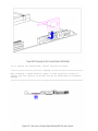
Serial Number
The serial number is displayed on the bottom of the CPU next to the memory
compartment cover.
Locating Additional Information
The following documentation is available to support these products:
o Quick Setup
o Reference Guide
o Introducing Microsoft Windows 95
o Compaq Service Quick Reference Guide
o Service Training Guides
o Compaq Service Advisories and Bulletins
o Compaq QuickFind
o Technical Reference Guide
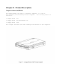
Chapter 1 - Product Description
Computer Features and Models
The Compaq Armada 1100 Family of Personal Computers is a line of
full-featured, Pentium-based portable computers. The following models are
available:
o Compaq Armada 1110
o Compaq Armada 1120 and Armada 1125
o Compaq Armada 1120T
This chapter describes the model offerings and features of the computers.
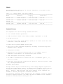
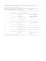
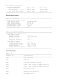
Models
The Compaq Armada 1100 Family of Personal Computers is available in the
models shown in Table 1-1.
Table 1-1. Compaq Armada 1100 Family Models
===========================================================================
Model
Processor
Display
Hard Drive
===========================================================================
Armada 1110
75-MHz Pentium
10.4-inch CSTN
810 MB
--------------------------------------------------------------------------Armada 1120
100-MHz Pentium
10.4-inch CSTN
810 MB
Armada 1125
--------------------------------------------------------------------------Armada 1120T
100-MHz Pentium
10.4-inch CTFT
810 MB
===========================================================================
Standard Features
The computers have the following standard features:
o 75 or 100-MHz Pentium processors
o 8 MB of dynamic random access memory (DRAM), expandable to 24 MB
o 810 MB hard drive
o 10.4-inch Color Super Twist Nematic (CSTN) or 10.4-inch Color Thin Film
Transistor (CTFT) VGA displays
o Nickel metal hydride (NiMH) battery pack
o Full-size 101-key compatible keyboard, including 12 function keys and
embedded numeric keypad
o Integrated trackball
o Operates from an internal battery pack or an AC adapter that is
compatible with domestic or international power sources
o Power management and security features
o Two PCMCIA standard device sockets that will accommodate Types I, II,
and III PC Cards
o Rear panel ports provide connectors for parallel and serial ports, video
out, and keyboard/mouse port
Software Fulfillment
Backup software may be ordered directly from Compaq Computer Corporation
through the Compaq Order Center. In Europe backup software may be ordered
using the Software Diskette Order Form which is included in the For
Help... booklet. Both the model and serial numbers of the computer are
needed to identify the specific software available.
For technical questions about software for the computer, contact a Compaq
Technical Support Engineer. The model and serial numbers of the computer
should be available before making the call.
Security Features
The computer has the following security features:
o Ability to secure the computer to an immovable object with an optional
cable lock.
o Ability to establish power-on and setup passwords.
o Ability to disable the following devices from the Security menu in
Computer Setup: serial port, parallel port, PC Card slots, diskette
drive, diskette drive boot ability.
Power Management
The computer supports three power management modes:
o Local Standby: The ability to send individual subsystems into reduced
power modes after predetermined periods of inactivity.
o Global Standby: The ability to place all subsystems in a reduced power
mode after a predetermined period of inactivity.
o Hibernation: The ability to save the system configuration and user data
to the hard disk, for restoration at a later time.
The OFF and ON states also involve power management. In the OFF state, the
computer appears to be consuming no power; however, as long as there is a
battery capable of supplying current, some components will be powered up,
performing housekeeping tasks and waiting to be awakened. In the ON state,
all systems are powered up and the unit is completely functional.
Computer Options
The options for the computer that are available from Compaq are described
in the following sections.
System Memory Options
The system memory options that are available from Compaq for the computers
are 8 and 16 MB memory expansion boards. The memory expansion boards are
70-ns Fast Page Mode DRAM SODIMMs, without parity. Maximum memory is 24 MB
of DRAM.
The expansion memory connector is a 144-pin SODIMM socket. Either parity
or non-parity SODIMMs may be used, but parity checking will not be enabled
by the memory controller.
Miscellaneous Options
The following options for the computer are also available from Compaq:
o AC Adapter
o Automobile Adapter
o Extended Life NiMH battery pack
o Slipcase
o AC power cords for international travelers
AC Adapter
The AC adapter supplies DC voltage to the system converter to operate
and/or charge the installed battery pack. The adapter provides sufficient
power to charge the battery pack in 1.5 hours or less with the system off,
or in 3.5 hours or less with the system on. The AC adapter power
specifications are presented in Chapter 7.
Automobile Adapter
The automobile adapter is used to charge the computer while traveling in
an automobile. The Auto Adapter power specifications are presented in
Chapter 7.
Nickel Metal Hydride Battery Pack
Nickel metal hydride battery packs are available for use with the Compaq
Armada 1100 Family of Personal Computers.
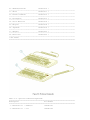
External Computer Components
The external computer components are shown and described in this section.
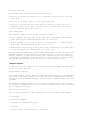
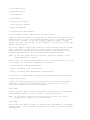
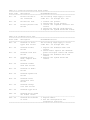
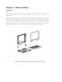
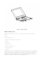
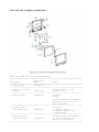
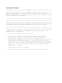
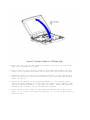
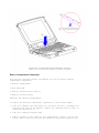
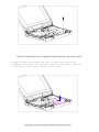
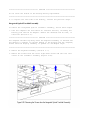
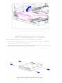
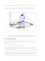
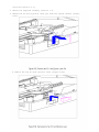
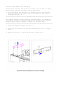
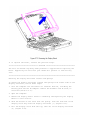
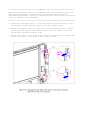
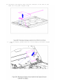
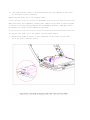
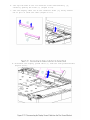
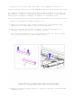
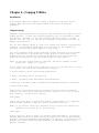
Front and Left Side Components
The front and left side external components are shown in the following
figure and described in this section:
[1] Handle bracket (2)
[2] Keyboard tilt feet
[3] Diskette drive
[4] PC Card slots
[5] Display latches (2)
[6] PC Card release levers
[7] Battery compartment button
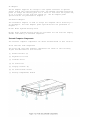
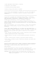
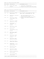
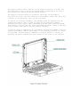
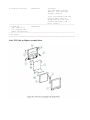
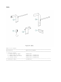
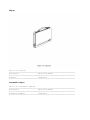
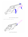
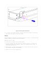
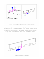
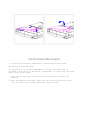
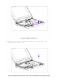
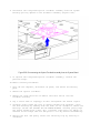
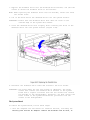
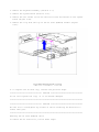
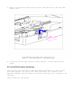
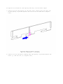
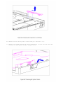
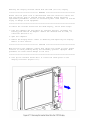
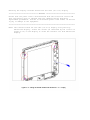
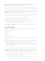
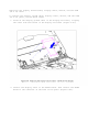
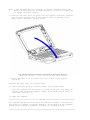
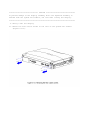
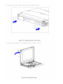
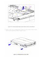
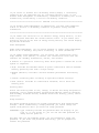
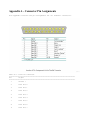
Rear Components
The rear components are shown in the following figure and identified in
this section:
[1] Power connector
[2] Parallel connector
[3] Serial connector
[4] Keyboard/mouse connector
[5] External monitor connector
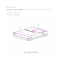
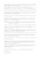
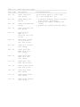
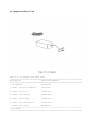
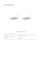
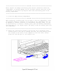
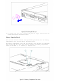
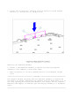
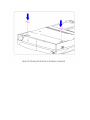
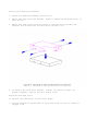
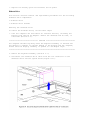
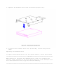
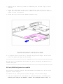
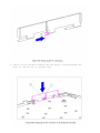
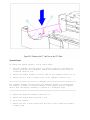
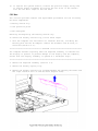
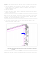
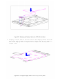
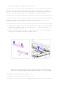
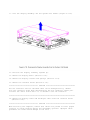
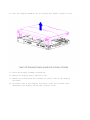
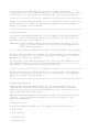
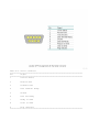
Bottom Components
The bottom external components are shown in the following figure and are
identified in this section:
[1] Battery compartment
[2] Memory compartment
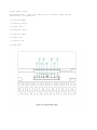
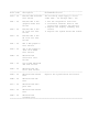
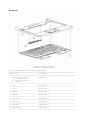
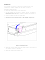
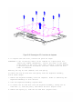
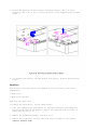
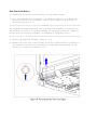
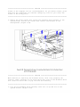
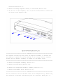
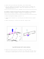
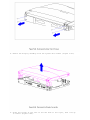
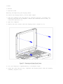
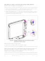
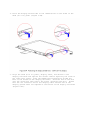
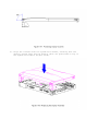
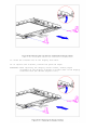
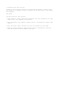
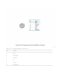
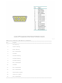
Status Panel Lights
The status panel lights are shown in the following figure and are
identified in this section:
[1] Power/standby
[2] Battery charge
[3] Hard drive
[4] Diskette drive
[5] Battery gauge
[6] Caps Lock
[7] Scroll Lock
[8] Num Lock
System Design
This section provides an overview of the system design.
System Board and Processor
The OPTi-designed Viper-N Chipset provides PCI bus, ISA bus, cache
controller, memory controller, and peripherals controller:
o OPTi 82C557M System Controller
o OPTi 82C556M Data Buffer Controller
o OPTi 82C558E Integrated Peripherals Controller
The computer supports a 75-MHz (P54C) CPU at 50-MHz bus speed, and a
100-MHz (P54LM) CPU at 66-MHz bus speed. Bus speed and processor core
voltage are configurable through resistor values at manufacturing. The
processor is soldered to the system board and is not removable.
System Memory Options
The main memory subsystem supports a standard 8 MB DRAM, expandable to a
maximum of 24 MB. The standard memory is soldered onto the system I/O
board. Expansion memory is available in 8 or 16 MB increments.
Diskette Drive
The computer uses a standard 3.5-inch, 1.44 MB diskette drive. The system
supports a single diskette drive in the computer.
Hard Drive
The computer supports an IDE hard drive. Cable select technology is
employed for device 0/device 1 selection. The hard drive mounts to the
system board with a hard drive bracket and connects directly to the system
board. A screw secures the hard drive bracket in place.
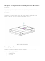
Computer Design Overview
This section presents a brief design overview of the computer. See Chapter
3 for an overview of the system unit and the display assembly from the
perspective of replacing components in the field. All replacement parts
are listed in Chapter 3, and removal and replacement procedures are
presented in Chapter 5.
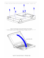
The computer is a traditional clam shell design with a display unit and a
system unit. The computer opens to reveal a backlighted LCD display and a
full-sized keyboard. The display is designed to open to 135o.
System Unit
The major components of the system unit are: the CPU cover, keyboard,
system board with processor, hard drive, diskette drive, memory expansion
board, battery pack and compartment, integrated trackball assembly,
Real-Time Clock battery, and PC Card (PCMCIA) ejector rails and
components.
Display Unit
The standard video subsystem consists of one of the following internal LCD
displays:
o 10.4-inch VGA CSTN display panel
o 10.4-inch VGA CTFT display panel
In addition, the video subsystem consists of:
o Cirrus Viking PCI Bus Graphics Accelerator with 1 MB EDO (two 70-ns
256kx 16) VRAM
o An inverter to supply AC power to the LCD backlight system
o A standard external VGA connector for use with CRTs and other VGA
compatible displays; also supported: external SVGA (maximum resolution
1024 x 768 x 256)
o A flex cable connecting the system board to the LCD display and the
inverter
o 48 KB of video ROM integrated into system ROM
Chapter 2 - Troubleshooting
Introduction
This chapter contains troubleshooting information for the computer. The
basic steps in troubleshooting include:
1. Completing the preliminary steps listed in Section 2.1.
2. Running the Power-On Self-Test (POST) as described in Section 2.4.
3. Running the Computer Checkup (TEST) as described in Section 2.5.
4. Performing the recommended actions described in the diagnostic tables
in Section 2.7 if you are unable to exercise POST or Computer Checkup
or if the problem persists after running POST and Computer Checkup.
Adhere to the following guidelines when troubleshooting:
o Complete the recommended actions in the order in which they are given.
o Repeat POST and Computer Checkup after each recommended action until the
problem is resolved and the error message does not return.
o Once the problem is resolved, do not complete the remaining recommended
actions.
o Refer to Chapter 5 for any removal and replacement procedures that are
recommended.
Preliminary Steps
IMPORTANT: Use the AC adapter when running POST, Computer Setup, or
Computer Checkup. A low battery condition could initiate
Standby and interrupt the test.
Before running POST and Computer Checkup, complete the following steps:
1. If a power-on password has been established, type the password and
press Enter.
NOTE: The key icon appears on the status display when the computer is
turned on to indicate that QuickLock/QuickBlank has been initiated.
Type the power-on password to exit QuickLock/QuickBlank. If the
password is unknown, it must be cleared (see Section 2.2).
2. Run Computer Setup (Section 2.3).
3. Use the Hotkeys to adjust the brightness (Fn+F9) and contrast (Fn+F10)
to the center of their ranges and leave the display open. On models
with color TFT displays, contrast is not adjustable.
4. Turn off the computer and all external devices.
5. Disconnect any external devices that you do not want to test. If you
want to use the printer to log error messages, leave it connected to
the computer.
NOTE: If a problem only occurs when an external device is connected to the
computer, the problem could be with the external device or its
cable. Isolate the problem by running POST with and without the
external device connected.
6. Use Advanced Diagnostics and loopback plugs in the serial and parallel
connectors if you plan to test these ports. To run Advanced
Diagnostics, complete the following steps:
a. Insert the Diagnostics diskette into the diskette drive and turn on
the computer.
b. At the Welcome Screen, enter Ctrl+A.
c. Press Enter to accept OK.
d. Select Computer Checkup (TEST).
e. Select Prompted Diagnostics after "Identifying System Hardware"
completes.
f. Select Interactive Testing and follow the displayed instructions.
7. Ensure that the battery pack is installed in the computer and the AC
adapter is connected to the computer and plugged into an AC power
source.
After completing the preliminary steps, run POST (Section 2.4) and
Computer Checkup (Section 2.5).
Running Computer Setup
The ROM-based Computer Setup displays the current system configuration and
allows you to set system and power management parameters. These parameters
are stored in CMOS, and a backup copy is saved in a parameter block in
system flash ROM.
You can access Computer Setup by pressing F10 when the prompt appears
after you turn on the computer. The following configuration parameters can
be changed in Computer Setup:
o Power conservation (when)
o Power conservation (level)
o Hibernation on/off
o Hibernation settings
o Warning beep
o Setup password
o Diskette drive disable
o Serial ports disable
o Parallel port disable
o PC Card slots disable
o Resume password on/off
o Boot memory test
o Keyboard numlock
o Boot sequence
o Boot display
o Serial port settings
o Parallel port settings
o Power-on password
o Diskette drive boot disable
To run Computer Setup, complete the following steps:
Computer Setup automatically recognizes and configures the system for new
Compaq devices. It does this without prompting you for information about
the devices. However, if you add a memory expansion board, a prompt
appears the next time you turn on the computer, notifying you of the new
memory configuration.
The first Computer Setup screen displays current settings for the system,
ports, and devices. The status bar at the bottom of the screen gives
instructions for navigating and choosing options. The status bar also
displays descriptions as you highlight menus and menu options.
NOTE: If the main system board is replaced, the serial number on this
screen changes to 0 (zero).
Select one of the menus from the menu bar at the top of the screen to view
or to change the following configuration settings:
o Initialization startup preferences
o Ports, including serial and parallel
o Power, including Power Management and Hibernation
o Security, including setup and power-on passwords and device disabling
Initialization Menu
Select the Initialization menu to change the initialization (startup)
settings for running the POST memory tests, numlock on or off, the
drive boot sequence, and the active display.
Ports Menu
Select the Ports menu to change the default input/output (I/O) addresses
and interrupt requests (IRQs) for serial and parallel ports.
NOTE: If you select conflicting settings for the ports, the system
automatically changes one of the settings.
Power Menu
Select the Power menu to enable or disable Power Management, low-battery
warning beeps, and an external energy-saving monitor. The factory default
settings are:
o Power Management Enabled While on Battery
o Conservation Level Medium
o Low-Battery Warning Beeps Enabled
o External Energy Saving Monitor Disabled
>>>>>>>>>>>>>>>>>>>>>>>>>>>>>>>>> CAUTION <<<<<<<<<<<<<<<<<<<<<<<<<<<<<<<<<
If you disable Power Management or Hibernation, you must take immediate
action to resolve a low-battery condition to prevent losing unsaved
information.
>>>>>>>>>>>>>>>>>>>>>>>>>>>>>>>>>>>>><<<<<<<<<<<<<<<<<<<<<<<<<<<<<<<<<<<<<<
If you elect to disable the low-battery warning beeps, a low-battery
condition is indicated only by a blinking battery light. If you disable
Power Management or Hibernation, information in memory is not
automatically saved during a critical low-battery condition.
If you enable the selection for an external energy-saving monitor, it
enters low-power mode when the screen timeout occurs. If you enable this
selection and do not have an energy-saving monitor, the screen display may
become distorted.
Under Power Management, you can select whether to enable Power Management
while on AC or battery power, only while on battery power, or never
(disabled).
If you enable Power Management, you can select from four conservation
levels: high, medium, none (drain), or custom. The conservation level sets
the timeouts for Standby, Hibernation, drives, and screens. A timeout is a
period of inactivity after which power is turned off to the system or
component.
o High: Provides the maximum amount of power conservation and the maximum
battery operating time from a single charge.
o Medium (default): Provides a balance between performance and battery
life.
o Custom: Conserves power according to specified timeout settings.
o None (Drain): Provides no power conservation features; the system runs
at full speed.
Security Menu
Select the Security menu to set, change, or delete the setup and power-on
passwords and to enable/disable QuickLock/QuickBlank, power-on password
from Standby, diskette drives, ports, and PC Card slots.
Setup Password
Use the Setup password to protect the system configuration from
unauthorized changes. After you establish the setup password, you cannot
change the system configuration until you enter the setup password.
IMPORTANT: Type carefully because the password does not display as you
type it. If you choose to, you can use the same password for
setup and for power-on.
The next time you press F10 (after POST) to run Computer Setup, a password
prompt appears on the screen. If you enter the password incorrectly, you
are prompted to reenter the password.
If you forget the setup password, you cannot change the system
configuration until the computer memory is cleared of the password. Refer
to Section 2.2 in this guide for procedures for clearing the password.
>>>>>>>>>>>>>>>>>>>>>>>>>>>>>>>>> CAUTION <<<<<<<<<<<<<<<<<<<<<<<<<<<<<<<<<
Record your setup password and put it in a safe place. If you forget your
setup password, you cannot reconfigure the computer until the computer
memory is cleared of the password.
>>>>>>>>>>>>>>>>>>>>>>>>>>>>>>>>>>>>><<<<<<<<<<<<<<<<<<<<<<<<<<<<<<<<<<<<<<
Power-On Password
The power-on password prevents use of the computer until the password is
entered. After you establish the power-on password, you must enter it
whenever you turn on the computer.
IMPORTANT: Type carefully because the password does not display as you
type it. If you choose to, you can use the same password for
setup and for power-on.
You can also select to require the power-on password when exiting Standby.
The next time you start the computer or exit Standby, a password prompt
appears. If you enter the password incorrectly, you are prompted to
reenter the password.
If you forget the power-on password, you cannot use the computer until the
computer memory is cleared of the password. Refer to Section 2.2 in this
guide for procedures for clearing the password.
>>>>>>>>>>>>>>>>>>>>>>>>>>>>>>>>> CAUTION <<<<<<<<<<<<<<<<<<<<<<<<<<<<<<<<<
Record the power-on password and put it in a safe place. If you forget
your power-on password, you cannot use the computer until the computer
memory is cleared of the password.
>>>>>>>>>>>>>>>>>>>>>>>>>>>>>>>>>>>>><<<<<<<<<<<<<<<<<<<<<<<<<<<<<<<<<<<<<<
QuickLock/QuickBlank
Enabling QuickLock/QuickBlank allows you to temporarily disable the
keyboard and clear the screen until the power-on password is entered.
After you have enabled QuickLock/QuickBlank, you can initiate it at any
time by pressing the Fn+F6 hotkey.
When QuickLock/QuickBlank is initiated, the key icon on the status panel
turns on. Type the power-on password on the blank screen to exit
QuickLock/QuickBlank.
Disabling Devices
The Security Menu provides a way to disable the following devices:
o Serial port
o Parallel port
o PC Card slots
o Diskette drive
Disabling these devices prevents the unauthorized transfer of data using
the devices. To reenable a device, deselect the Disable option and restart
the computer.
Exit Menu
The Exit menu has four options:
o Save and Exit: Saves configuration changes, but some changes do not take
effect until the computer is restarted.
o Exit (No Save): Exits and does not save the changes you have made.
o Restore Factory Defaults: Replaces the current configuration settings
with the original factory default settings.
POST Error Messages
This chapter contains typical error messages that you may encounter during
the power-on self-test (POST). POST is a series of tests that run every
time you turn on the computer. POST verifies that the system is configured
and functioning properly. A successful POST is followed by one or two
short beeps.
If you receive an error message listed on the following pages, follow the
recommended action. If you receive an error message that is not listed,
run Computer Checkup from the Diagnostics diskette. Information about
running Computer Checkup is presented later in this chapter.
If POST detects an error, one of the following events occurs:
o A message with the prefix "WARNING" appears informing you where the
error occurred. The system pauses until you press F1 to continue.
o A message with the prefix "FATAL" appears informing you where the error
occurred. After the message, the system emits a series of audible beeps.
The system then stops.
o The system emits a series of audible beeps. The system then stops.
Warning messages indicate a potential problem exists such as a system
configuration error. When F1 is pressed, the system should resume. You
should be able to correct problems that produce WARNING messages.
IMPORTANT: When a WARNING message includes the prompt to "RUN SCU," run
Computer Setup. (Computer Setup replaces the SCU utility.)
Fatal errors emit a beep and may display a FATAL message. Fatal errors
indicate severe problems, such as a hardware failure. Fatal errors do not
allow the system to resume. Some of the Fatal error beep codes are listed
at the end of this section.
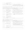
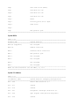
Table 2-1. Warning Messages
===========================================================================
Message
Description
===========================================================================
Clock not ticking correctly
The real time clock is not ticking.
--------------------------------------------------------------------------CMOS checksum invalid, run
CMOS RAM information has been corrupted and
SCU
needs to be reinitialized by running Computer
Setup.
--------------------------------------------------------------------------CMOS failure, run SCU
CMOS RAM has lost power and needs to be
reinitialized by running Computer Setup.
--------------------------------------------------------------------------Floppy controller failed
The diskette drive controller failed to
respond to the reset command. Power down the
system and check all appropriate connections.
If the diskette drive controller continues to
fail, you may need to replace the system
board.
--------------------------------------------------------------------------Floppy disk track 0 failed
The diskette drive cannot read track 0 of the
diskette in the drive. Try another diskette.
If the problem persists, you may need to
replace the diskette drive.
--------------------------------------------------------------------------Floppy information invalid,
The drive parameters stored in CMOS RAM do
run SCU
not match the diskette drives detected in the
system. Run Computer Setup
--------------------------------------------------------------------------Hard disk controller error
The hard drive controller failed to respond
to the reset command. Check the drive
parameters. Power down the system and check
all appropriate connections.
--------------------------------------------------------------------------Hardware information does
The video adapter type specified in CMOS RAM
not match video card, run
does not match the installed hardware. Run
SCU
Computer Setup
--------------------------------------------------------------------------Keyboard controller failure
The keyboard failed the self-test command.
--------------------------------------------------------------------------Keyboard failure
The keyboard failed to respond to the RESET
ID command.
--------------------------------------------------------------------------No interrupts from Timer 0
The periodic timer interrupt is not
occurring.
--------------------------------------------------------------------------RAM parity error at
A RAM parity error occurred at the specified
location xxxx
(hex) location.
--------------------------------------------------------------------------ROM at xxxx (LENGTH yyyy)
An illegal adapter ROM was located at the
with nonzero checksum (zz)
specified address. An external adapter (such
as a video card) may be causing the conflict.
--------------------------------------------------------------------------Time/Date corrupt - run SCU
The time and date stored in the real time
clock have been corrupted, possibly by a
power loss. Run Computer Setup.
--------------------------------------------------------------------------Unexpected amount of
The amount of memory detected by POST does
memory, run SCU
not match the amount specified in CMOS RAM.
Run Computer Setup.
--------------------------------------------------------------------------Hard disk xx failure
A failure or an error occurred when trying to
(or error)
access the hard drive.
===========================================================================
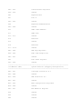
Table 2-2. Fatal Error Messages
===========================================================================
Message
Description
Beep Code
===========================================================================
CMOS RAM test failed
A walking bit test of CMOS RAM
location 0E (Hex) - 3F (Hex) failed.
3
--------------------------------------------------------------------------DMA controller faulty
A sequential read/write of the
transfer count and transfer address
registers within the primary and
secondary DMA controllers failed.
4
--------------------------------------------------------------------------Faulty DMA page
registers
A walking bit read/write of the 16 DMA
controller page registers starting at
location 80 Hex failed.
0
--------------------------------------------------------------------------Faulty refresh
circuits
A continuous read/write test of port
61h found that bit 4 (Refresh Detect)
failed to toggle within an allotted
amount of time.
1
--------------------------------------------------------------------------Interrupt controller
failed
A sequential read/write of various
Interrupt Controller registers failed.
5
--------------------------------------------------------------------------ROM checksum incorrect
A checksum of the ROM BIOS does not
match the byte value at F000:FFFF.
2
--------------------------------------------------------------------------RAM error at location
xxxx
RAM error occurred during memory test.
None
--------------------------------------------------------------------------Parity error at
unknown location
Parity error occurred.
None
===========================================================================
The following table lists some of the Fatal Error beep codes, along with
the beep sequence (short, long, pause) and the meaning of the beeps.
Table 2-3. Fatal Error Beep Codes
===========================================================================
Beep Code
Beep Sequence
Explanation
Remedy
===========================================================================
0
S-S-S-P-S-S-L-P
The DMA page
registers are faulty.
Replace system board.
1
S-S-S-P-S-L-S-P
The refresh circuitry
is faulty.
Replace system board.
2
S-S-S-P-S-L-L-P
The ROM checksum is
incorrect.
3
S-S-S-P-L-S-S-P
The CMOS RAM test
failed.
Replace system board.
The DMA controller is
faulty.
Replace system board.
The interrupt
controller failed.
Replace system board.
The keyboard
controller failed.
Replace system board.
Graphics adapter is
faulty.
Replace system board.
4
5
6
7
8
S-S-S-P-L-S-L-P
S-S-S-P-L-L-S-P
S-S-S-P-L-L-L-P
S-S-L-P-S-S-S-P
S-S-L-P-S-S-L-P
Internal RAM is
faulty.
1. Flash the ROM
2. Replace system
board.
Replace processor
board.
--------------------------------------------------------------------------S = Short, L = Long, P = Pause
===========================================================================
Compaq Diagnostics
Run the Compaq Diagnostics utilities diskette when you want to view or
test system information and installed or connected devices. The
Diagnostics menu includes the following utilities:
o Computer Checkup (TEST)
o View System Information (INSPECT)
o Prepare Computer for a Compaq Service Call (RemotePaq)
If you have a problem you cannot solve, run the Diagnostics utilities
before you call for support. Run Computer Checkup and select to save the
device list to a file and to print or to save the log of errors. Run the
View System Information (INSPECT) utility and select to print or to save
that information. Have the files or the printed information available when
you call for support.
Computer Checkup (TEST)
Computer Checkup (TEST) determines whether the various computer components
and devices are recognized by the system and are functioning properly. You
can display, print, or save the information generated by Computer Checkup.
Follow these steps to run Computer Checkup:
1. Plug the computer into an external power source. (A low battery
condition could interrupt the program.)
2. Turn on the external devices that you want to test. Connect the printer
if you want to print a log of error messages.
3. Insert the Compaq Diagnostics diskette in drive A.
4. Turn on or restart the computer. The computer starts from drive A, and
the Diagnostics Welcome screen appears.
5. Press Enter to continue. The Diagnostics menu appears.
6. Select Computer Checkup from the Diagnostics menu. A Test Option menu
appears.
7. Select "View the Device List" from the Test Option menu. A list of the
installed Compaq devices appears.
8. If the list of installed devices is correct, select OK. The Test Option
menu appears.
NOTE: If the list is incorrect, ensure that any new devices are
installed properly.
9. Select one of the following from the Test Option menu:
o Quick Check Diagnostics. Runs a quick, general test on each device
with a minimal number of prompts. If errors occur, they display when
the testing is complete. You cannot print or save the error
messages.
o Automatic Diagnostics. Runs unattended, maximum testing of each
device with minimal prompts. You can choose how many times to run the
tests, to stop on errors, or to print or save a log of errors.
o Prompted Diagnostics. Allows maximum control over testing the
devices. You can choose attended or unattended testing, decide to
stop on errors, or choose to print or save a log of errors.
10. Follow the instructions on the screen as the devices are tested. When
testing is complete, the Test Option menu appears.
11. Exit the Test Option menu.
12. Exit the Diagnostics menu.
View System Information (INSPECT)
The View System Information (INSPECT) utility provides information about
the computer and installed or connected devices. You can display, print,
or save the information.
Follow these steps to run INSPECT from the Compaq Diagnostics diskette:
1. Turn on the external devices that you want to test. Connect the printer
if you want to print the information.
2. Insert the Compaq Diagnostics diskette into drive A.
3. Turn on or restart the computer. The computer starts from drive A, and
the Diagnostics Welcome screen appears.
4. Press Enter to continue. The Diagnostics menu appears.
5. Select View System Information (INSPECT) from the Diagnostics menu.
6. Select the item you want to view from the following list:
===========================================================================
System
Memory
===========================================================================
ROM
Audio
Keyboard
Operating system
System ports
System files
System storage
Windows files
Graphics
===========================================================================
7. Follow the instructions on the screen to cycle through the screens, to
return to the list and choose another item, or to print the
information.
RemotePaq
This utility is only available in certain geographical areas and requires
a modem. It allows a Compaq reseller or service provider to automatically
run diagnostics on the computer.
To run RemotePaq, follow these steps:
1. Insert the Compaq Diagnostics diskette into drive A.
2. Turn on or restart the computer. The computer starts from drive A, and
the Diagnostics Welcome screen appears.
3. Press Enter to continue. The Diagnostics menu appears.
4. Select Prepare Computer for a Compaq Service Call (RemotePaq).
5. Follow the instructions on screen.
Diagnostic Error Codes
Diagnostic error codes occur if the system recognizes a problem while
running the Compaq Diagnostic program. These error codes help identify
possibly defective subassemblies.
Tables 2-4 through 2-13 list possible error codes, a description of the
error condition, and the action required to resolve the error condition.
IMPORTANT: Retest the system after completing each step. If the problem
has been resolved, do not proceed with the remaining steps.
For assistance in the removal and replacement of a particular subassembly,
see Chapter 5, "Computer Removal and Replacement Procedures."
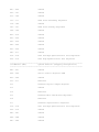
Table 2-4. Processor Test Error Codes
===========================================================================
Error Code
Description
Recommended Action
===========================================================================
101 - xx
CPU test failed
The following applies to error codes
101 - xx through 113 - xx:
103 - xx
DMA page registers
test failed
Replace the system board and retest.
104 - xx
Interrupt controller
master test failed
105 - xx
Port 61 error
106 - xx
Keyboard controller
self-test failed
107 - xx
CMOS RAM test
failed
108 - xx
CMOS interrupt test
failed
109 - xx
CMOS clock test
failed
110 - xx
Programmable timer
load data test
failed
113 - xx
Protected mode test
failed
--------------------------------------------------------------------------114 - 01
Speaker test failed
1. Check system configuration.
2. Verify cable connections to speaker.
3. Replace the system board and retest.
===========================================================================
Table 2-5. Memory Test Error Codes
===========================================================================
Error Code
Description
Recommended Action
===========================================================================
200 - xx
Memory machine ID
The following steps apply to error
test failed
codes 200 - xx and 202 - xx:
202 - xx
Memory system ROM
1. Flash the system ROM and retest.
checksum failed
2. Replace the system board and retest.
--------------------------------------------------------------------------203 - xx
Write/Read test
The following steps apply to error
failed
codes 203 - xx through 215 - xx:
204 - xx
Address test failed
211 - xx
Random pattern test
failed
214 - xx
Noise test failed
1. Remove the memory module and retest.
2. Install a new memory module and
retest.
215 - xx
Random address test
failed
===========================================================================
Table 2-6. Keyboard Test Error Codes
===========================================================================
Error Code
Description
Recommended Action
===========================================================================
300 - xx
Failed ID Test
The following steps apply to error
codes 300 - xx through 304 - xx:
301 - xx
Failed Self-test/
Interface Test
302 - xx
Failed Individual
Key Test
304 - xx
1. Check the keyboard connection. If
disconnected, turn off the computer
and connect the keyboard.
2. Replace the keyboard and retest.
3. Replace the system board and retest.
Failed Keyboard
Repeat Test
===========================================================================
Table 2-7. Parallel Printer Test Error Codes
===========================================================================
Error Code
Description
Recommended Action
===========================================================================
401 - xx
Printer failed or
The following steps apply to error
not connected
codes 401 - xx through 403 - xx:
402 - xx
Failed Port Test
1. Connect the printer.
2. Check power to the printer.
403 - xx
Printer pattern test
3. Install the loopback connector and
failed
retest.
4. Check port and IRQ configuration.
5. Replace the system board and retest.
===========================================================================
Table 2-8. Diskette Drive Test
===========================================================================
Error Code
Description
Recommended Action
===========================================================================
600 - xx
Diskette ID drive
The following steps apply to error
types test failed
codes 600 - xx through 698 - xx:
601 - xx
Diskette format
failed
602 - xx
Diskette read test
failed
603 - xx
Diskette write,
read, compare test
failed
604 - xx
Diskette random
read test failed
605 - xx
Diskette ID media
failed
606 - xx
Diskette speed test
failed
609 - xx
Diskette reset
controller test
failed
610 - xx
Diskette change
line test failed
697 - xx
Diskette type error
698 - xx
1. Replace the diskette media and
retest.
2. Check and/or replace the diskette
power and signal cables and retest.
3. Replace the diskette drive and
retest.
4. Replace the system board and
retest.
Diskette drive speed
not within limits
--------------------------------------------------------------------------699 - xx
Diskette drive/media
1. Replace media.
ID error
2. Run the Configuration and
Diagnostics Utilities.
===========================================================================
Table 2-9. Serial Test Error Codes
===========================================================================
Error Code
Description
Recommended Action
===========================================================================
1101 - xx
Serial port test
1. Check port configuration
failed
2. Replace the system board and retest.
===========================================================================
Table 2-10. Hard Drive Test Error Codes
===========================================================================
Error Code
Description
Recommended Action
===========================================================================
1701 - xx
Hard drive format
The following steps apply to error
test failed
codes 1701 - xx through 1736 - xx:
1702 - xx
Hard drive read test
failed
1703 - xx
Hard drive write/
read/compare test
failed
1704 - xx
Hard drive random
seek test failed
1705 - xx
Hard drive
controller test
failed
1706 - xx
Hard drive ready
test failed
1707 - xx
Hard drive
recalibration test
failed
1708 - xx
Hard drive format
bad track test
failed
1709 - xx
Hard drive reset
controller test
failed
1710 - xx
Hard drive park
head test failed
1715 - xx
Hard drive head
select test failed
1716 - xx
Hard drive
conditional format
test failed
1717 - xx
Hard drive ECC *
test failed
1719 - xx
Hard drive power
mode test failed
1724 - xx
Network preparation
test failed
1736 - xx
1. Run the Diagnostics Utilities
and verify drive type.
2. Replace the hard drive and retest.
3. Replace the system board and
retest.
Drive monitoring
test failed
--------------------------------------------------------------------------* ECC = Error Correction Code
===========================================================================
Table 2-11. Video Test Error Codes
===========================================================================
Error Code
Description
Recommended Action
===========================================================================
501 - xx
Video controller
The following apply to error codes
test failed
501 - xx through 516 - xx:
502 - xx
Video memory test
failed
503 - xx
Video attribute test
failed
504 - xx
Video character set
test failed
505 - xx
Video 80 x 25
mode 9 x 14
character cell test
failed
506 - xx
Video 80 x 25 mode
8 x 8 character
cell test failed
507 - xx
Video 40 x 25 mode
test failed
508 - xx
Video 320 x 200
mode color set 0
test failed
509 - xx
Video 320 x 200
mode color set 1
test failed
510 - xx
Video 640 x 200
mode test failed
511 - xx
Video screen memory
page test failed
512 - xx
Video gray scale
test failed
514 - xx
Video white screen
test failed
516 - xx
Video noise pattern
test failed
1. Disconnect external monitor and test
with internal LCD display.
2. Replace the display assembly and
retest.
3. Replace the system board and retest.
--------------------------------------------------------------------------Error Code
Description
Recommended Action
--------------------------------------------------------------------------2402 - xx
Video memory test
The following steps apply to error
failed
codes 2402 - xx through 2456 - xx:
2403 - xx
Video attribute test
failed
2404 - xx
Video character set
test failed
2405 - xx
Video 80 x 25 mode
9 x 14 character
cell test failed
2406 - xx
Video 80 x 25 mode
8 x 8 character
cell test failed
2408 - xx
2409 - xx
Video 320 x 200
mode color set 1
test failed
2410 - xx
Video 640 x 200
mode test failed
2411 - xx
Video screen
memory page test
failed
2412 - xx
Video gray scale
test failed
2414 - xx
Video white screen
test failed
2416 - xx
Video noise
pattern test
failed
2418 - xx
ECG/VGC memory
test failed
1. Run the Configuration and
Diagnostics Utilities.
2. Replace the display assembly and
retest.
3. Replace the system board and retest.
--------------------------------------------------------------------------Error Code
Description
Recommended Action
--------------------------------------------------------------------------2419 - xx
ECG/VGC ROM checksum
The following steps apply to error
test failed
codes 2402 - xx through 2456 - xx:
2421 - xx
ECG/VGC 640 x 200
graphics mode test
failed
2422 - xx
ECG/VGC 640 x 350
16 color set test
failed
2423 - xx
ECG/VGC 640 x 350
64 color set test
failed
2431 - xx
640 x 480 graphics
test failure
2432 - xx
320 x 200 graphics
(256 color mode)
test failure
2448 - xx
Advanced VGA
Controller test
failed
2451 - xx
132-column Advanced
VGA test failed
1. Run the Diagnostics Utilities.
2. Disconnect external monitor and
retest with internal LCD monitor.
3. Replace the display assembly and
retest.
4. Replace the system board and retest.
2456 - xx
Advanced VGA 256
Color test failed
--------------------------------------------------------------------------2458 - xx
Advanced VGA BitBLT
Replace the system board and retest.
test
2468 - xx
Advanced VGA DAC
test
2477 - xx
Advanced VGA data
path test
2478 - xx
Advanced VGA BitBLT
test
2480 - xx
Advanced VGA
Linedraw test
===========================================================================
Table 2-12. Audio Test Error Codes
===========================================================================
Error Code
Description
Recommended Action
===========================================================================
3206 - xx
Audio System
Replace the system board and retest.
Internal Error
===========================================================================
Table 2-13. Pointing Device Interface Test Error Codes
===========================================================================
Error Code
Description
Recommended Action
===========================================================================
8601 - xx
Mouse test failed
The following steps apply to 8601 - xx
and 8602 - xx:
8602 - xx
Interface test
failed
1. Replace the Pointing Device and
reset.
2. Replace the system board and retest.
===========================================================================
Troubleshooting without Diagnostics
This section provides information about how to identify and correct some
common hardware, memory, and software problems. It also explains several
types of common messages that may be displayed on the screen. The
following pages contain troubleshooting information on:
o Audio
o Memory
o Battery/Battery gauge
o PC Card
o Diskette/Diskette drive
o Power
o Hard drive
o Printer
o Hardware installation
o Screen (LCD and CRT)
o Keyboard (Numeric keypad)
o Software
o Pointing device
Solving Minor Problems
Some minor problems and possible solutions are outlined in the following
tables. If the problem appears related to a software application, check
the documentation provided with the software.
Solving Audio Problems
Some common audio problems and solutions are listed in the following
table.
Table 2-14. Solving Audio Problems
===========================================================================
Problem
Probable Cause
Solution(s)
===========================================================================
Computer beeps once
This is typical; it
No action is required.
after you turn it
indicates successful
on.
completion of the Power-On
Self-Test (POST).
--------------------------------------------------------------------------Computer does not
Speaker volume is off or
If the speaker icon is
beep after the
has been turned down.
not displayed on the
Power-On Self-Test
status panel, Press
(POST).
Fn+F5 to turn the
speaker on, then adjust
the volume.
Beeps have been turned
Run Computer Setup and
off.
turn on beeps.
===========================================================================
Solving Battery and Battery Gauge Problems
Some common causes and solutions for battery problems are listed in the
following table. The "Solving Power Problems" section in this chapter also
may be applicable.
Table 2-15. Solving Battery and Battery Gauge Problems
===========================================================================
Problem
Probable Cause
Solution(s)
===========================================================================
Computer won't turn
Battery is discharged.
Connect the computer to
on when battery pack
an external power
is inserted and
source and charge the
power cord is
battery pack.
unplugged.
Replace the battery pack
with a fully charged
battery pack.
Check the battery
connectors on the system
board to verify they are
evenly spaced and that
they are not bent or
broken.
--------------------------------------------------------------------------Computer is beeping
Battery charge is low.
Immediately save any open
and battery light
file(s). Then do any one
is blinking.
of the following:
o Connect the computer to
an external power
source to charge the
battery pack.
o Initiate Standby and
replace the battery
pack with a fully
charged battery pack.
o Turn the computer off
or initiate Hibernation
until you can find
another power source or
charge the battery
pack.
--------------------------------------------------------------------------Computer battery
Low battery beeps
Run Computer Setup to
light blinks to
were turned off.
turn on the low battery
indicate low battery
warning beeps.
condition, but
computer does not
beep.
Volume is turned off or
turned down too low.
Press Fn+F5 to turn the
speaker on and then
adjust the volume.
--------------------------------------------------------------------------Problem
Probable Cause
Solution(s)
--------------------------------------------------------------------------Battery light
Battery pack is already
No action is necessary.
doesn't light and
charged.
battery pack won't
fast charge.
Battery pack was exposed
to temperature extremes.
Allow time for the
battery pack to return to
room temperature.
Battery pack is at end
Replace battery pack.
of its life.
--------------------------------------------------------------------------You have to set the
Auxiliary battery charge
Provide power to the
date and time every
is low, or the auxiliary
computer (AC or battery).
time you turn on
battery is at end of its
the computer.
life.
Replace the RTC (lithium)
battery.
--------------------------------------------------------------------------Battery charge does
Battery is being exposed
Keep the battery pack
not last as long as
to high temperatures or
within the recommended
expected.
extremely cold
temperature ranges:
temperatures.
Operating: 50oF to 104oF
(10oC to 40oC)
Storage: -4oF to 86oF
(-20oC to 30oC).
Recharge the battery
pack.
Battery has partially
self-discharged.
Recharge the battery.
Discharge the battery
completely and then
recharge it.
Power management is
disabled.
Set a power management
level in Computer Setup.
An external device or
Turn off or disconnect
PC Card is draining the
external devices when not
battery.
using them.
--------------------------------------------------------------------------Battery pack is
Normal warming has
No action is required.
warm to the touch
occurred due to
after charging.
charging.
--------------------------------------------------------------------------Battery gauge is
The battery pack is new
Fully charge the battery
inaccurate.
or has not been used for
pack until the battery
a long period.
light on the computer
turns off.
Condition the battery
pack by fully charging,
then fully discharging,
and then fully
recharging. If condition
persists, replace the
battery. If the battery
gauge is still
inaccurate, replace the
system board.
--------------------------------------------------------------------------Battery pack
Power management is
Enable power management
operating time is
turned off or disabled.
in Computer Setup and in
far less than the
Windows Power Properties.
documented
The power management icon
average operating
should be visible on the
time.
status panel.
An external device or
PC Card is draining the
battery.
Turn off or disconnect
external devices when not
using them.
Battery pack has
partially selfdischarged.
Condition the battery
pack by fully charging,
fully discharging, then
fully recharging it.
To maintain the charge,
leave battery packs in
the computer when it is
connected to external
power.
If the computer is
disconnected from
external power for more
than two weeks, remove
battery packs from the
computer to reduce the
discharge rate.
--------------------------------------------------------------------------Problem
Probable Cause
Solution(s)
--------------------------------------------------------------------------Battery pack is being
Keep the battery pack
exposed to high
within the recommended
temperatures or
temperature ranges.
extremely cold
temperatures.
operating: 50oF to 104oF
(10oC to 40oC)
storage: -4oF to 86oF
(-20oC to 30oC ).
Recharge the battery
pack.
===========================================================================
Solving Diskette and Diskette Drive Problems
Some common causes and solutions for diskette and diskette drive problems
are listed in the following table.
Table 2-16. Solving Diskette and Diskette Drive Problems
===========================================================================
Problem
Probable Cause
Solution(s)
===========================================================================
Diskette drive icon
Diskette drive is not
Remove the diskette drive
does not turn on.
installed properly.
and install it properly.
--------------------------------------------------------------------------Diskette drive icon
Diskette is damaged.
Run SCANDISK on the
stays on.
diskette. At the system
prompt, enter SCANDISK A:
Diskette is incorrectly
inserted.
Remove diskette and
reinsert.
Software program is
Check the program
damaged.
diskettes.
--------------------------------------------------------------------------Diskette drive
Diskette is
Disable the diskette's
cannot write to a
write-protected.
write-protect feature or
diskette.
use a diskette that is
not write-protected.
Computer is writing to
the wrong drive.
Check the drive letter in
the path statement.
Not enough space is left
on the diskette.
Use another diskette.
Drive error has
occurred.
Run Computer Checkup
from the Compaq
Diagnostics diskette.
Diskette is not
formatted.
Format the diskette. At
the system prompt, enter
FORMAT A:
--------------------------------------------------------------------------Diskette drive
The wrong type of
Use the type of diskette
cannot read a
diskette is being used.
required by the drive.
diskette.
Diskette has a bad
sector.
Copy files to hard drive
or another diskette.
Reformat bad floppy.
Drive error has
occurred.
Run Computer Checkup
from the Compaq
Diagnostics diskette.
Diskette is not
formatted.
Format the diskette. At
the system prompt, enter
FORMAT A:
--------------------------------------------------------------------------Cannot boot from
Bootable diskette is not
Put the bootable diskette
diskette
in drive A
in drive A.
Diskette Boot is
Run Computer Setup and
disabled in Computer
enable Diskette Boot on
Setup.
the Initialization menu.
===========================================================================
Solving Hard Drive Problems
Some common causes and solutions for hard drive problems are listed in the
following table.
>>>>>>>>>>>>>>>>>>>>>>>>>>>>>>>>> CAUTION <<<<<<<<<<<<<<<<<<<<<<<<<<<<<<<<<
To prevent loss of information, always maintain an up-to- date backup of
your hard drive at all times, in case of errors or failures.
>>>>>>>>>>>>>>>>>>>>>>>>>>>>>>>>>>>>><<<<<<<<<<<<<<<<<<<<<<<<<<<<<<<<<<<<<<
Table 2-17. Solving Hard Drive Problems
===========================================================================
Problem
Probable Cause
Solution(s)
===========================================================================
Reading hard drive
System entered
Give the system time to
takes an unusually
Hibernation due to
restore the previously
long time after
low-battery condition
saved data to its exact
restarting the
and is now exiting from
state before Hibernation.
computer.
it.
--------------------------------------------------------------------------Hard drive error
Hard drive has bad
Run Computer Checkup from
occurs.
sectors or has failed.
the Compaq Diagnostics
diskette.
See POST error messages.
===========================================================================
Solving Hardware Installation Problems
Some common causes and solutions for hardware installation problems are
listed in the following table.
Table 2-18. Solving Hardware Installation Problems
===========================================================================
Problem
Probable Cause
Solution(s)
===========================================================================
A new device is not
Cable(s) of new external
Ensure that all cables
recognized as part
device are loose or
are properly and securely
of the computer
power cables are
connected.
system.
unplugged.
Power switch of new
external device is not
turned on.
Turn off the computer,
turn on the external
device, then turn on the
computer to integrate
the device with the
computer system.
Device is not seated
Turn off the computer
properly.
and reinsert the device.
===========================================================================
Solving Keyboard/Numeric Keypad Problems
Some common causes and solutions for keyboard/numeric keypad problems are
listed in the following table.
Table 2-19. Solving Keyboard/Numeric Keypad Problems
===========================================================================
Problem
Probable Cause
Solution(s)
===========================================================================
Embedded numeric
Num Lock function is not
Press the Fn+NumLk keys
keypad on computer
enabled.
to enable the Num Lock
keyboard is
function and embedded
disabled.
numeric keypad. The Num
Lock icon on the status
panel turns on.
--------------------------------------------------------------------------Embedded numeric
External numeric keypad
Disconnect the external
keypad is disabled
is connected to the
numeric keypad from the
and Num Lock
computer.
computer.
function is on.
--------------------------------------------------------------------------Keyboard is locked.
You initiated QuickLock.
Enter your password to
exit QuickLock.
===========================================================================
Solving Pointing Device Problems
Some common causes and solutions for trackball and mouse problems are
listed in the following table.
Table 2-20. Solving Pointing Device Problems
===========================================================================
Problem
Probable Cause
Solution(s)
===========================================================================
External pointing
The device driver is not
Install the device driver
device does not
installed in Windows.
in Windows.
work.
--------------------------------------------------------------------------Integrated pointing
An external pointing
Initiate Standby and
device does not
device is connected
disconnect the external
work.
and the system has
pointing device.
disabled the internal
pointing device.
===========================================================================
Solving Memory Problems
Some common causes and solutions for memory problems are listed in the
following table.
Table 2-21. Solving Memory Problems
===========================================================================
Problem
Probable Cause
Solution(s)
===========================================================================
Memory count during
Optional memory
Ensure that the optional
Power-On Self-Test
expansion card is
memory expansion card is
(POST) is incorrect.
installed incorrectly,
installed correctly.
is incompatible with the
computer, or is
defective.
--------------------------------------------------------------------------"Out of Memory"
System ran out of memory
Check the application
message is displayed
for the application.
documentation for
on the screen or
memory requirements.
insufficient memory
Install additional
error occurs during
memory.
operation.
Too many TSR (terminate
Remove from memory any
and stay resident)
TSR applications that
applications are
you do not need.
running.
===========================================================================
Solving PC Card Problems
Some common causes and solutions for PC Card problems are listed in the
following table.
Table 2-22. Solving PC Card Problems
===========================================================================
Problem
Probable Cause
Solution(s)
===========================================================================
PC Card error
The PC Card slot is
Run Computer Setup and
messages appear when
disabled.
enable the PC Card slots
the computer is
on the Security Menu.
turned on.
When turned on, the
computer does not
beep when a PC
Card is inserted.
Card is not inserted
properly.
Ensure the card is
inserted in the correct
orientation.
PC Card beeps are
disabled.
Double-click the PC Card
icon in the Control
Panel, click the Global
Settings tab, the enable
PC Card sound effects.
Speaker is turned off.
Press Fn+F5 to turn the
speaker on.
PC Card drivers are not
installed.
Double click the Add New
Hardware icon in the
Control Panel for
installation
instructions.
If PC Card or drivers are
not compatible with
Windows 95, install
drivers and use the PC
Card in MS-DOS mode.
The PC Card slots are
disabled.
Card or card driver is
not supported.
Run Computer Setup and
then select the Security
menu to enable PC Card
slots.
Contact your Compaq
authorized service
provider for a list of
PC Cards tested
successfully in Compaq
PC Card platforms.
--------------------------------------------------------------------------The PC Card drivers
The PC Card slot is
Run Computer Setup and
(Socket Services,
disabled.
select the Security menu
Card Services, Card
to enable PC Card slots.
ID) fail with error
messages when the
computer is turned
on.
--------------------------------------------------------------------------PC Card modem, fax,
Card is not fully
Ensure the card is
or network card
inserted into the slot
inserted in the correct
does not work.
or is not inserted
orientation.
properly.
Telephone cord is not
plugged in all the way.
Check and secure
telephone connection.
Necessary drivers are
Install drivers.
not installed (turned
on).
--------------------------------------------------------------------------PC Card modem or fax
You are trying to access
Right click My Computer
card does not work.
the card using the wrong
on the Windows desktop.
COM port.
Left click Properties,
then Device Manager,
and double-click Port
Settings to view the
COM port settings.
The card conflicts with
a serial device.
The card is not
Use supported cards
supported.
only.
--------------------------------------------------------------------------Modem network PC
Network driver is not
Install driver.
Card does not work.
installed or is not set
up properly.
Telephone cord is not
Verify telephone
properly connected.
connection.
--------------------------------------------------------------------------Memory or storage
SRAM and flash memory
Install driver.
card does not work.
cards require the memory
card driver to be loaded
(turned on).
Flash memory cards
require the Microsoft
FlashFile System to be
loaded.
Hard drives on flash
mass storage cards
require the PC Card ATA
driver to be loaded.
You are trying to
access the hard drive
card using the wrong
drive letter.
The card is not
supported.
Double-click My Computer
to verify the drive
letter assigned to the
card.
Check the list of PC
Cards tested successfully
in Compaq PC Card
platforms.
===========================================================================
Solving Power Problems
Also see "Solving Battery and Battery Gauge Problems" in this chapter.
Table 2-23. Solving Power Problems
===========================================================================
Problem
Probable Cause
Solution(s)
===========================================================================
Computer won't turn
Computer is not
Insert battery or connect
on and battery pack
connected to a power
an external power source.
is not inserted.
source.
Power cords to the
external power source
are unplugged.
Ensure that power cords
connecting the computer
and the external power
source are plugged in
properly.
System board is
defective.
1. See section
"Measuring Power
Signals" to check for
proper voltages.
2. Replace system board
and restart.
--------------------------------------------------------------------------Computer turned off
System initiated
Replace the battery pack
while it was left
Hibernation due to a
with a fully charged
unattended and the
critical low-battery
battery pack or connect
power icon is off.
condition.
the computer to an
external power source.
Then turn on the
computer.
System initiated
Turn on the computer.
Hibernation after a
preset timeout.
--------------------------------------------------------------------------Computer initiated
The unit temperature was
Computer is in an
Standby
exceeded.
exceedingly hot
automatically or
environment. Let the
turned off
computer cool down.
automatically.
===========================================================================
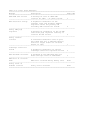
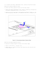
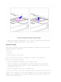
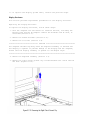
Measuring Power Signals
The following power signals can be measured on the top side of the PCA.
===========================================================================
VDD (+5V)
Across Tantalum CAPs C574, C573
--------------------------------------------------------------------------+3.3V
Across Tantalum CAPs C578, C575
--------------------------------------------------------------------------VCPU (3.3V on -001
and 2.9V on -002)
Across Tantalum CAPs C572, C571, C570, and C569
--------------------------------------------------------------------------VBAT
At Fuse F1
--------------------------------------------------------------------------+12V
Across CAP C522, near PCMCIA connector
===========================================================================
VCC1 can be measured at Pin 28 of U539.
Solving Printer Problems
If you experience problems printing, run a printer self-test. Refer to the
documentation provided with your printer for instructions. If the
self-test fails, it is a printer-specific problem. Also refer to the
printing section of your application documentation.
Table 2-24. Solving Printer Problems
===========================================================================
Problem
Probable Cause
Solution(s)
===========================================================================
Printer will not
The signal cable may not
Ensure that the signal
turn on.
be connected properly,
cable is properly
or the printer is
connected and that the
unplugged.
power cord is connected
to the electrical outlet.
--------------------------------------------------------------------------Printer will not
Printer is not turned on
Turn the printer on and
print.
or is off line.
set it to online.
The device drivers for
your application are not
installed.
Refer to the printer
documentation to Install
the correct printer
driver.
Printer that is set up
for a network is not
connected to the
network.
Connect the printer to
the network.
Printer cable is too
long, unshielded, or
defective.
Replace the cable.
Paper tray is empty.
Fill the paper tray with
paper and set the
printer to on line.
---------------------------------------------------------------------------
Printer prints
garbled
information.
Correct printer drivers
are not installed.
Refer to the printer
documentation to Install
the correct printer
driver.
Cable is not connected
properly.
Ensure that the printer
signal cable is properly
connected to the
computer.
Cable is defective.
Replace the printer
cable and retest.
===========================================================================
Solving Screen Problems
This section lists some common causes and solutions for computer display
and external monitor problems.
IMPORTANT: Verify that the display jumpers are set properly for the
display before proceeding with any troubleshooting.
You can perform a monitor self-test on an external VGA color or monochrome
monitor by disconnecting the monitor from the computer. To do so, complete
the following steps:
1. Turn off the monitor.
2. Turn off the computer.
3. Disconnect the monitor signal cable from the computer.
4. Turn on the monitor and allow it to warm up for one minute.
The screen should be white. A narrow black border may also appear on
the left and right sides of the display. Either of these displays
indicates that the monitor is working properly.
Table 2-25. Solving Screen Problems
===========================================================================
Problem
Probable Cause
Solution(s)
===========================================================================
Characters are dim.
The brightness or
Adjust the control(s) on
contrast (if applicable)
the right side of the
control is not set
computer display.
properly.
Computer screen is in
Tilt the display or move
direct light.
computer.
--------------------------------------------------------------------------Screen is blank.
You initiated QuickLock/
Enter the password to
QuickBlank.
exit QuickLock/
QuickBlank.
You may have another
screen blanking utility
installed.
Press any key and/or
enter your password.
Screen save was
initiated after the
Power Management timeout
period of inactivity
Press any key or click
the mouse.
If an STN screen is
used, brightness/
contrast needs
adjusting.
Use the control on the
display to adjust the
brightness/contrast.
Standby was initiated.
Press the standby button
to exit Standby.
--------------------------------------------------------------------------Computer screen is
Display was switched to
Press the Fn+F4 hotkey to
blank and the screen
the external monitor.
display information on
on an external
the computer screen.
monitor displays
information.
--------------------------------------------------------------------------Garbled characters
You are using 800 x 600
Restart your computer. If
on internal display
or higher resolution on
simultaneous display is
or flashing internal
external display and
desired, use 640 x 480
display when
have toggled back to
resolution.
connected to
internal display, which
external monitor.
only supports 640 x 480
resolution.
--------------------------------------------------------------------------The image on the
You are using an
This is typical; no
external monitor
external monitor and
action is required.
does not fill the
simultaneously
screen.
displaying an image on
the computer display.
--------------------------------------------------------------------------Small red, green, or
Small spots, called
This is typical; no
blue spots appear on
on-pixels, often appear
action is required.
the computer TFT
on TFT screens. Compaq
display.
limits the number of
these on-pixels to
0.003 percent of the
approximately 1 million
transistors that are on
a 10.4-inch display.
===========================================================================
Solving Software Application Problems
Most software application or installation problems occur as a result of
one or more of the following:
o The application was not installed correctly.
o The CONFIG.SYS file was not configured correctly.
o Memory was not allocated correctly.
o The AUTOEXEC.BAT file was not edited correctly.
o A conflict exists between applications.
Table 2-26. Solving Software Application Problems
===========================================================================
Problem
Probable Cause
Solution(s)
===========================================================================
Cannot use an
The application has not
Run the program with the
application.
been added to the PATH
full path name.
statement.
--------------------------------------------------------------------------Insufficient memory
System ran out of memory
Check the application
to run application.
for the application.
documentation for memory
requirements.
Install additional
memory.
Too many TSR (terminate
Remove from memory any
and stay resident)
TSR applications that you
applications are
do not need.
running.
===========================================================================
Chapter 3 - Illustrated Parts
Introduction
This chapter provides an illustrated parts breakdown and a reference for
spare part numbers for the Compaq Armada 1100 Family of Personal
Computers.
The computer combines a display assembly and system unit module. The
display and system unit module are joined together by clutches on either
side, which are secured by screws in the chassis and display enclosure,
and which allow the display to open and close. The system unit module is
secured to the CPU base by screw locks in the rear and screws in the
bottom of the system unit enclosure. The display assembly is secured by
screws installed in the front bezel of the display enclosure.
System Unit Module Overview
The system unit module (Figure 3-2) contains the following major
components:
o Hard drive - The hard drive mounts to the system chassis with a hard
drive bracket and connects directly to the system board with no
intervening cables. The hard drive bracket attaches to the hard drive
with four screws. The drive is protected by an insulator between the
system board and the drive.
o Memory expansion board - System memory can be upgraded with an optional
memory expansion board. An expansion board is added or replaced from the
bottom of the computer through the memory compartment cover. The memory
expansion board connects directly to the system board with one
connector.
o Battery pack - The nickel metal hydride battery pack is accessed through
the battery compartment.
o Integrated trackball assembly - The optical trackball is centrally
located at the bottom of the keyboard assembly. The assembly consists of
the trackball, retaining ring, and connector. The trackball assembly
connects directly to the system board and is secured by two screws.
o System board with processor - The system board is mounted directly to
the system chassis. All removable components connected to the system
board, except for the PC Card rails, EMI clip, and heatspreader must be
removed prior to removing the system board. The processor is soldered to
the system board and is not removable. It is covered by a heatspreader
designed to dissipate heat generated by the processor. There is a
bottom heatsink on the chassis, beneath the system board and the
processor. A spare parts kit containing a replacement system board comes
with the processor and heatspreader built on it. A chassis spare parts
kit includes the bottom heatsink.
o PC Card rails - The PC Card rails are replaceable and are secured by two
screws from the bottom of the system board and a clip on top of the
rails. The header attaches directly to the system board and cannot be
removed. The top and bottom PC Card ejection levers are replaceable.
o Real-Time Clock Battery - The battery is located in the left corner at
the rear of the computer.
o Diskette drive - The diskette drive attaches to the system board by a
bracket and three screws; the bracket also attaches to the heatspreader
with two screws. The drive is connected by a diskette drive cable and
LIF connector. The bracket attaches to the drive with four screws. The
drive is protected by an insulator between the system board and the
drive.
The memory expansion board and battery pack are accessed from the bottom
of the computer. To service the remaining system unit module components,
the keyboard assembly must be removed. A complete list of replaceable
parts is included in Table 3-1.
Display Assembly Overview
All display assemblies (Figure 3-3) include the following replaceable
parts:
o Bezel
o Enclosure latches
o Liquid crystal display (LCD) panel
o Shield
o Enclosure
o Display cable
o Display ground cable
o Inverter board
o Clutches
The display cable is a prefolded, flex cable that connects to the display
inverter board with a low insertion force (LIF) connector. The other end
of the display cable is exposed at the bottom of the display enclosure and
connects to the system board with a zero insertion force (ZIF) slide
connector. The cable connects to the display panel directly on the CTFT
model and through a crossover PCA on the CSTN models.
The display ground cable connects to the display shield on one end, and
the other end clips to the flex ground bracket located above the serial
port between the system board and system chassis.
The display inverter board is aligned to the right of the display
enclosure with pins. One end connects to the display cable; the other end
connects to the backlight cable of the LCD panel.
To replace the display assembly, the assembly must be removed from the
system unit module. This is done by removing the keyboard assembly,
disconnecting the display cable and display ground cable from the system
unit module, removing the tilt feet and handle brackets, removing the rear
clutch screws, and lifting off the display assembly.
To service display components, do not remove the display assembly from the
system unit module (unless replacement of the display enclosure or clutch
is required). Access display components (inverter board or latches) by
removing the bezel secured with four screws on the front of the display.
System Unit Module Parts
Table 3-1. System Unit Module
===========================================================================
Description
Spare Part Number
Notes
===========================================================================
1. Base enclosure
262492-001
Includes:
a. PC Card eject levers and
pin
b. bottom PC Card door and
spring
c. battery latch button and
spring
d. handle bracket, screws,
and washers
e. battery shield, insulator
f. tilt foot and screws
g. battery clip
h. battery warning label *
i. lock plate *
j. label - A2860E, Service *
k. label - AY2860F,
Service *
---------------------------------------------------------------------------
2. System board
- with 75 MHz
processor
Includes:
a. heatspreader plate
262406-001
b. diskette drive and hard
drive insulators *
- with 100 MHz
c. EMI gasket *
processor
262407-001
d. heatspreader clip *
e. heatspreader screws *
--------------------------------------------------------------------------3. Diskette drive
bracket
189240-001
--------------------------------------------------------------------------4. Diskette drive
147963-001
Includes:
a. label *
b. battery clip, spring,
spacer assembly *
c. sleeve, 4x4 floppy *
--------------------------------------------------------------------------5. Real-time clock
Includes Read this First
battery
117099-001
card *
--------------------------------------------------------------------------6. Optical trackball
189197-001
--------------------------------------------------------------------------7. PC Card ejection
Includes the following:
assembly
189242-001
a. rails
b. clip
c. screws *
--------------------------------------------------------------------------8. Chassis
262493-001
Includes:
a. bottom heatsink assembly
b. battery clip *
--------------------------------------------------------------------------9. Clutches
147858-001
Includes:
a. Left and right clutches
b. handle bracket screws and
washers
c. tilt foot screws
--------------------------------------------------------------------------10. Hard drive 810 MB
262468-001
--------------------------------------------------------------------------11. Hard drive bracket
147872-001
--------------------------------------------------------------------------12. Trough
189262-001
--------------------------------------------------------------------------13. Left and right
189262-001
See Table 3-11 for contents
clutch ground
(Miscellaneous
of Miscellaneous/hardware kit
clips
hardware kit)
--------------------------------------------------------------------------14. Memory expansion
board *
8 MB
220584-001
Includes Tamper Evident
16 MB
220585-001
labels *
--------------------------------------------------------------------------15. NiMH battery
Includes Battery
pack *
190626-001
Installation card *
--------------------------------------------------------------------------16. Screws kit *
(See Table 3-12
for contents and
where used
matrix.)
147885-001
--------------------------------------------------------------------------* Not Shown
===========================================================================
Color STN (10.4 in) Display Assembly Parts
Table 3-2. CSTN (10.4 in) Display Assembly
===========================================================================
Spare Part
Description
Number
Notes
===========================================================================
1. Display bezel
189246-001
--------------------------------------------------------------------------2. Backlight inverter
Includes Caution, High
board
189135-001
Voltage label
--------------------------------------------------------------------------3. Display panel
262466-001
Includes:
shield
display shipping box assembly,
Read This First card, and
cable depressor *
--------------------------------------------------------------------------4. Display cables
Includes:
with XOVER board
262494-001
a. display cable
b. display ground cable
c. XOVER board
--------------------------------------------------------------------------5. Display clutch
Includes screws and washers
(left and right)
147858-001
for handle bracket, and
screws for tilt feet *
---------------------------------------------------------------------------
6. Display enclosure
189245-001
Includes:
left and right latches,
springs, left and right
display clutches
logos (for Armada 1100 and
Contura 400), pad for
Sharp CSTN (for use with
Contura 400 CSTN), and
bezel screws *
--------------------------------------------------------------------------7. Screw kit *
147885-001
(See Table 3-12
for contents and
where used matrix.)
--------------------------------------------------------------------------* Not Shown
===========================================================================
Color TFT (10.4 in) Display Assembly Parts
Table 3-3. CTFT (10.4 in) Display Assembly
===========================================================================
Spare Part
Description
Number
Notes
===========================================================================
1. Display bezel
189244-001
--------------------------------------------------------------------------2. Backlight inverter
Includes Caution, High
board
189136-001
Voltage label *
--------------------------------------------------------------------------3. Display panel
189114-001
Includes:
shield
display shipping box assembly *
--------------------------------------------------------------------------4. Display cables
189247-001
Includes:
with XOVER board
a. display cable (CTFT)
b. display ground cable
c. display cable (CSTN)
d. XOVER board for CSTN *
--------------------------------------------------------------------------5. Display clutch
Includes screws and washers
(left and right)
147858-001
for handle bracket, and screws
for tilt feet *
--------------------------------------------------------------------------6. Display enclosure
189243-001
Includes:
left and right latches,
springs, left and right display
clutches
logos (for Armada 1100 and
Contura 400), and bezel
screws *
--------------------------------------------------------------------------7. Screw kit *
147885-001
(See Table 3-12
for contents and
where used matrix.)
--------------------------------------------------------------------------* Not Shown
===========================================================================
Keyboards
Table 3-4. Armada 1100 Notebook Keyboards
===========================================================================
Description
All Models
===========================================================================
1. CPU cover includes:
147860-001
a. PC Card door
b. light deflector
c. spring *
--------------------------------------------------------------------------2. U.S.
147875-001
--------------------------------------------------------------------------3. U.K.
147875-003 *
--------------------------------------------------------------------------4. German
147875-004 *
--------------------------------------------------------------------------5. French
147875-005 *
--------------------------------------------------------------------------6. Italian
147875-006 *
--------------------------------------------------------------------------7. Spanish
147875-007 *
--------------------------------------------------------------------------8. Danish
147875-008 *
--------------------------------------------------------------------------9. Norwegian
147875-009 *
---------------------------------------------------------------------------
10. Swedish/Finnish
147875-010 *
--------------------------------------------------------------------------11. Swiss
147875-011 *
--------------------------------------------------------------------------12. French Canadian
147875-012 *
--------------------------------------------------------------------------13. Portuguese
147875-013 *
--------------------------------------------------------------------------14. Latin American
147875-016 *
--------------------------------------------------------------------------15. Belgian
147875-018 *
--------------------------------------------------------------------------16. Japanese
147875-019 *
--------------------------------------------------------------------------17. Hangeul
147875-033 *
--------------------------------------------------------------------------18. Brazilian
147875-035 *
--------------------------------------------------------------------------* Not Shown
===========================================================================
Table 3-5. Optional Enhanced Keyboards
===========================================================================
Description
All Models
===========================================================================
1. Enhanced III - Domestic
140536-101
2. Enhanced III - U.K.
140536-103
3. Enhanced III - German
140536-104 *
4. Enhanced III - French
140536-105 *
5. Enhanced III - Italian
140536-106 *
6. Enhanced III - Spanish
140536-107 *
7. Enhanced III - Danish
140536-108 *
8. Enhanced III - Norwegian
140536-109 *
9. Enhanced III - Swedish/Finnish
140536-110 *
10. Enhanced III - Swiss
140536-111 *
11. Enhanced III - French Canadian
140536-112 *
12. Enhanced III - Portuguese
140536-113 *
13. Enhanced III - Turkish
140536-114 *
14. Enhanced III - Greek
140536-115 *
15. Enhanced III - Latin American
140536-116 *
16. Enhanced III - Arabic
140536-117 *
17. Enhanced III - Belgian
140536-118 *
18. Enhanced III - Japanese
140536-119 *
19. Enhanced III - BHCSY **
140536-120 *
20. Enhanced III - Hungarian
140536-121 *
21. Enhanced III - Polish
140536-122 *
22. Enhanced III - Slovakian
140536-123 *
23. Enhanced III - Russian
140536-124 *
24. Enhanced III - Czech
140536-129 *
25. Enhanced III - Thai
140536-130 *
26. Enhanced III - Beijing
140536-132 *
27. Enhanced III - Hangeul
140536-133 *
28. Enhanced III - Taipei
140536-134 *
29. Enhanced III - Brazil
140536-135 *
--------------------------------------------------------------------------* Not Shown
** Bosnia - Herzegovina, Croatia, Slovenia, and Yugoslavia
===========================================================================
Cables
Table 3-6. Cables
===========================================================================
Description
Spare Part Number
===========================================================================
1. Display cables
a. CTFT display cable
189247-001
b. CSTN display cable
189247-001, 262494-001
c. XOVER board for CSTN
189247-001, 262494-001
d. Ground cable
189247-001, 262494-001
--------------------------------------------------------------------------2. Diskette cable
147866-001
===========================================================================
AC Adapter and Power Cord
Table 3-7. AC Adapter and Power Cord
===========================================================================
Description
Spare Part Numbers
===========================================================================
1. AC adapter
147679-002
2. Power cord (U.S./Canada)
197230-001
3. Power cord (U.K.)
197232-001 *
4. Power cord (Europe)
197231-001 *
5. Power cord (Japan)
197233-001 *
6. Power cord (Australia)
197234-001 *
7. Power cord (Korea)
262488-001 *
--------------------------------------------------------------------------* Not shown
===========================================================================
Memory Expansion Boards
Table 3-8. Memory Boards
===========================================================================
Description
Spare Part Numbers
===========================================================================
Memory expansion boards
1. 8 MB
220584-001
2. 16 MB
220585-001
===========================================================================
Slipcase
Table 3-9. Slipcase
===========================================================================
Description
Spare Part Number
===========================================================================
Slipcase
194162-001
===========================================================================
Automobile Adapter
Table 3-10. Automobile Adapter
===========================================================================
Description
Spare Part Number
===========================================================================
Automobile Adapter
218079-001
===========================================================================
Miscellaneous CPU Kits
Table 3-11. Miscellaneous CPU Kits
===========================================================================
Description
Spare Part Number
===========================================================================
Miscellaneous/hardware
189262-001
Includes:
Tilt feet
Trough
Battery latch
PCMCIA door
Foot shoulder screws
Battery tray assembly
Extension spring (battery eject button,
display latches)
Lock plate
Flex ground bracket
Keyboard ground clips
Left and right clutch ground clips
Handle bracket
Memory assembly door
PC Card ejection levers and pin
--------------------------------------------------------------------------System clock battery
117099-001
--------------------------------------------------------------------------Handle
147678-001
--------------------------------------------------------------------------Keyboard warning labels
189288-001
--------------------------------------------------------------------------Logos
189292-001
--------------------------------------------------------------------------Memory door
169713-001
--------------------------------------------------------------------------Anti-skid feet
147859-001
--------------------------------------------------------------------------RomPaq upgrade
181088-001
--------------------------------------------------------------------------Trackball removal tool
147779-001
--------------------------------------------------------------------------Country kit - domestic retail
262538-001
--------------------------------------------------------------------------Miscellaneous screws kit (See Table 3-12
for contents and where used matrix.)
147885-001
--------------------------------------------------------------------------Shipping carton, (Quantity = 5)
262485-001
--------------------------------------------------------------------------Shipping carton with buns, (Quantity = 1)
262486-001
===========================================================================
Computer Miscellaneous Screws Kit
Table 3-12a. Computer Miscellaneous Screws Kit Contents and Use
===========================================================================
Description
Spare Part Number
===========================================================================
Screws and Fasteners Kit
147885-001
===========================================================================
Table 3-12b. Computer Miscellaneous Screws Kit Contents and Use
===========================================================================
Description:
M2.0
Type:
Fillister
Where Used:
PCMCIA header
Drive:
T8
Quantity Required:
2
--------------------------------------------------------------------------Description:
M2.0
Type:
Fillister
Where Used:
PCMCIA rails
Drive:
T8
Quantity Required:
2
--------------------------------------------------------------------------Description:
M3.0
Type:
Truss
Where Used:
Heatspreader to system board
Drive:
T8
Quantity Required:
3
--------------------------------------------------------------------------Description:
M2.5 x 5.0
Type:
Where Used:
Diskette drive bracket to system board
Drive:
SL/T8
Quantity Required:
3
--------------------------------------------------------------------------Description:
M2.5 x 5.0
Type:
Where Used:
PCA
Drive:
SL/T8
Quantity Required:
6
--------------------------------------------------------------------------Description:
M2.5 x 5.0
Type:
Where Used:
Display assembly - internal
Drive:
SL/T8
Quantity Required:
6
--------------------------------------------------------------------------Description:
M2.5 x 5.0
Type:
Where Used:
Bezel
Drive:
SL/T8
Quantity Required:
4
--------------------------------------------------------------------------Description:
M2.5 x 5.0
Type:
Where Used:
Lower clutch
Drive:
SL/T8
Quantity Required:
4
---------------------------------------------------------------------------
Description:
M2.5 x 5.0
Type:
Where Used:
Trackball assembly to base
Drive:
SL/T8
Quantity Required:
2
--------------------------------------------------------------------------Description:
M2.5 x 5.0
Type:
Where Used:
Hard drive bracket to system chassis
Drive:
T8
Quantity Required:
1
--------------------------------------------------------------------------Description:
M2.5 x 4.0
Type:
Where Used:
CPU cover to keyboard
Drive:
SL/T8
Quantity Required:
7
--------------------------------------------------------------------------Description:
M2.5 x 24.0
Type:
Where Used:
Bottom of unit
Drive:
SL/T8
Quantity Required:
7
--------------------------------------------------------------------------Description:
M2.5
Type:
Shoulder
Where Used:
Handle Bracket to clutch/through CPU base
Drive:
T8
Quantity Required:
2
--------------------------------------------------------------------------Description:
M3.0
Type:
Truss
Where Used:
Hard drive bracket to hard drive
Drive:
T8
Quantity Required:
4
--------------------------------------------------------------------------Description:
M3.0
Type:
Truss
Where Used:
Diskette drive bracket to diskette drive
Drive:
T8
Quantity Required:
2
--------------------------------------------------------------------------Description:
M2.6
Type:
Fillister
Where Used:
Diskette drive bracket to diskette drive
Drive:
T8
Quantity Required:
4
--------------------------------------------------------------------------Description:
Type:
Screw lock
Where Used:
Back of unit
Drive:
3/16" Hex
Quantity Required:
6
--------------------------------------------------------------------------Description:
M3.0
Type:
Truss
Where Used:
Panel Display
Drive:
T8
Quantity Required:
4
--------------------------------------------------------------------------Description:
M2.5 x 10.0
Type:
Truss
Where Used:
Heatspreader to chassis
Drive:
T8
Quantity Required:
1
===========================================================================
Documentation
Table 3-13. Documentation
===========================================================================
Description
Spare Part Numbers
===========================================================================
Maintenance and Service Guide
262489-001
Illustrated Parts Map
262490-001
Armada 1100 Family Reference Guide
and Quick Setup
262539-001 *
--------------------------------------------------------------------------* To order these documents in other languages, use the following
extensions: -041 German, -051 French, -061 Italian, -101 Swedish, -331
Dutch, -081 Danish, -351 Finnish, -091 Norwegian, -161 Latin American
Spanish, -201 Brazilian Portuguese, -191 Japanese, and -AD1 Hangeul.
===========================================================================
Chapter 4 - Removal and Replacement Preliminaries
Introduction
This chapter provides general service information for the Compaq Armada
1100 Family of Personal Computers.
Adherence to the procedures and precautions described in this chapter is
essential for proper service.
Electrostatic Discharge
A sudden discharge of static electricity from a finger or other conductor
can destroy static-sensitive devices or microcircuitry. Often the spark is
neither felt or heard, but damage occurs. An electronic device exposed to
electrostatic discharge (ESD) may not be affected at all and will work
perfectly throughout a normal cycle. Or it may function normally for a
while, then degrade in the internal layers, reducing its life expectancy.
Networks built into many integrated circuits provide some protection, but
in many cases, the discharge contains enough power to alter device
parameters or melt silicon junctions.
Generating Static
Table 4-1 shows how different activities generate static electricity and
at different electrostatic voltage levels.
Table 4-1. Typical Electrostatic Voltages
===========================================================================
-- Relative Humidity -Event
10%
40%
55%
===========================================================================
Walking across carpet
35,000 V
15,000 V
7,500 V
--------------------------------------------------------------------------Walking across vinyl floor
12,000 V
5,000 V
3,000 V
--------------------------------------------------------------------------Motions of bench worker
6,000 V
800 V
400 V
--------------------------------------------------------------------------Removing DIPS from plastic
tubes
2,000 V
700 V
400 V
--------------------------------------------------------------------------Removing DIPS from vinyl
trays
11,500 V
4,000 V
2,000 V
--------------------------------------------------------------------------Removing DIPS from Styrofoam
14,500 V
5,000 V
3,500 V
--------------------------------------------------------------------------Removing bubble pack from
PCBs
26,000 V
20,000 V
7,000 V
--------------------------------------------------------------------------Packing PCBs in foam-lined
box
21,000 V
11,000 V
5,000 V
--------------------------------------------------------------------------NOTE: 700 volts can degrade a product.
===========================================================================
Preventing Electrostatic Damage to Equipment
Many electronic components are sensitive to ESD. Circuitry design and
structure determine the degree of sensitivity. The following proper
packaging and grounding precautions are necessary to prevent damage:
o Protect all electrostatic parts and assemblies with conductive or
approved containers or packaging.
o Keep electrostatic-sensitive parts in their containers until they arrive
at static-free stations.
o Place items on a grounded surface before removing them from their
container.
o Always be properly grounded when touching a sensitive component or
assembly.
o Place reusable electronic-sensitive parts from assemblies in protective
packaging or conductive foam.
Use transporters and conveyors made of antistatic belts and metal roller
bushings. Mechanized equipment used for moving materials must be wired to
ground and proper materials selected to avoid static charging. When
grounding is not possible, use an ionizer to dissipate electric charges.
Removing Batteries
Compaq recommends that you remove all batteries from the computer before
beginning the disassembly procedures. Failure to do so could cause damage
to computer components.
Preventing Damage to Drives
To prevent static damage to hard drives, use the following precautions:
o Handle drives gently, using static-guarding techniques.
o Store drives in the original shipping containers.
o Avoid dropping drives from any height onto any surface.
o Handle drives on surfaces that have at least one inch of shock proof
foam.
o Always place drives with the PCB assembly side down on the foam.
Grounding Methods
The method for grounding must include a wrist strap or a foot strap at a
grounded workstation. When seated, wear a wrist strap connected to a
grounded system. When standing, use footstraps and a grounded floor mat.
Table 4-2. Static-Shielding Protection Levels
===========================================================================
Method
Voltages
===========================================================================
Antistatic Plastic
1,500
Carbon-Loaded Plastic
7,500
Metallized Laminate
15,000
===========================================================================
Grounding Workstations
To prevent static damage at the workstation, use the following
precautions:
o Cover the workstation with approved static-dissipative material. Provide
a wrist strap connected to the work surface and properly grounded tools
and equipment.
o Use static-dissipative mats, heel straps, or air ionizers to give added
protection.
o Handle electrostatic sensitive components, parts, and assemblies by the
case or PCB laminate. Handle them only at static-free workstations.
o Avoid contact with pins, leads, or circuitry.
o Turn off power and input signals before inserting and removing
connectors or test equipment.
o Use fixtures made of static-safe materials when fixtures must directly
contact dissipative surfaces.
o Keep work area free of non-conductive materials such as ordinary plastic
assembly aids and Styrofoam.
o Use field service tools, such as cutters, screwdrivers, vacuums, that
are conductive.
o Use a portable field service kit with a static dissipative vinyl pouch
that folds out of a work mat. Also use a wrist strap and a ground cord
for the work surface. Ground the cord to the chassis of the equipment
undergoing test or repair.
Grounding Equipment
Use the following equipment to prevent static electricity damage to the
equipment:
Wrist Straps are flexible straps with a minimum of 1 megohm +/- 10%
resistance to the ground cords. To provide proper ground, a strap must be
worn snug against the skin. On grounded mats without banana-plug
connectors, connect a wrist strap with alligator clips.
Heel straps/Toe straps/Bootstraps can be used at standing workstations and
are compatible with most types of boots and shoes. On conductive floors or
dissipative floor mats, use straps on both feet with a minimum of 1 megohm
resistance between operator and ground. To be effective, the conductive
strips must be worn in contact with the skin.
Recommended Materials and Equipment
Other materials and equipment that are recommended for use in preventing
static electricity include:
o Antistatic tape
o Antistatic smocks, aprons, or sleeve protectors
o Conductive bins and other assembly or soldering aids
o Conductive foam
o Conductive table-top workstations with ground cord of 1 megohm of
resistance
o Static dissipative table or floor mats with hard tie to ground
o Field service kits
o Static awareness labels
o Wrist straps and footwear straps providing 1 megohm +/- 10% resistance
o Material handling packages
o Conductive plastic bags
o Conductive plastic tubes
o Conductive tote boxes
o Metal tote boxes
o Opaque shielding bags
o Transparent metallized shielding bags
o Transparent shielding tubes
Service Considerations
Listed below are some of the considerations that should be kept in mind
during the disassembly and assembly of the computer.
Tool Requirements
o Torx T-8 screwdriver
o Flat-bladed screwdriver
o Tool kit, Compaq part number 100767-001 (includes case utility tool,
connector removal tool, and loopback plugs)
o 3/16-inch hex socket wrench
o Preloaded application diskettes (Compaq Order Center, 1-800-952-7689)
Cables and Connectors
Apply only the tension required to seat or unseat the cables during
insertion or removal from connectors. Handle cables by the connector or
pull tabs whenever possible. In all cases, avoid bending, twisting, or
tearing the cables, and ensure that cables are placed in such a way that
they cannot be caught or snagged by parts being removed or replaced.
>>>>>>>>>>>>>>>>>>>>>>>>>>>>>>>>> CAUTION <<<<<<<<<<<<<<<<<<<<<<<<<<<<<<<<<
When servicing these computers, ensure that cables are placed in their
proper location during the reassembly process. Improper cable placement
can cause severe damage to the unit.
>>>>>>>>>>>>>>>>>>>>>>>>>>>>>>>>>>>>><<<<<<<<<<<<<<<<<<<<<<<<<<<<<<<<<<<<<<
Serial Number
The computer serial numbers should be provided to Compaq whenever
requesting information or ordering spare parts. The serial number is
located on the bottom of the CPU next to the memory compartment cover.
Chapter 5 - Computer Removal and Replacement Procedures
Introduction
This chapter provides complete removal and replacement procedures for the
computer.
Serial Number
The computer serial number should be reported to Compaq when requesting
information or ordering spare parts. The serial number is displayed on the
bottom of the CPU, next to the memory compartment cover [1].
Disassembly Sequence Chart
Use the following chart to determine the section number and disassembly
sequence for removing components from the computer.
5.3
|-|
|
|
|
|
Preparing the Computer
|--AC Adapter
|--Diskette
|--Battery pack
|--PC Card
5.4
5.5
5.6
5.7
5.8
5.9
5.10
5.11
5.12
5.13
5.14
5.15
5.16
5.17
5.18
5.19
5.20
5.21
5.22
5.23
|-|
|-|
|-|
|-|
|
|
|
|-|
|
|
|
|-|
|-|
|-|
|-|
|
|
|-|
|-|
|-|
|-|
|-|
|
|-|
|
|
|
|-|
|
|
|
|-|
|
|
|
|
|-|
|
|
|
|
|-|
|--
Handle bracket
Tilt
Memory expansion board
Keyboard assembly
|-- Keyboard
|-- CPU cover
|-- Top PC Card (PCMCIA) door and spring
Battery compartment components
|-- Battery compartment
|-- Anti-skid pad
|-- Battery release spring and button
Hard drive
Real-time clock battery
Integrated optical trackball assembly
Diskette drive assembly
|-- Diskette drive
|-- Diskette drive bracket
System board
PC Card (PCMCIA) assembly
PC Card ejection levers and pin
PC Card doors and springs
System chassis
|-- Trough
CPU
|-|-|--
base
Battery shield clip
Lock provision plate
Anti-skid pads
Display assembly components
|-- Bezel
|-- Latches
|-- Inverter board
Color STN (10.4") display
|-- LCD panel
|-- Shield
|-- Display cable
|-- Display ground cable
Color TFT (10.4") display
|-- LCD panel
|-- Display cable
|-- Shield
|-- Display ground cable
Display enclosure
Clutches and ground clips
Preparing the Computer
>>>>>>>>>>>>>>>>>>>>>>>>>>>>>>>>> WARNING <<<<<<<<<<<<<<<<<<<<<<<<<<<<<<<<<
Ensure that the power cord is disconnected from the electrical outlet and
that the battery pack is removed from the computer before beginning
replacement procedures. Failure to disconnect power could result in serious
injury or damage to the equipment.
>>>>>>>>>>>>>>>>>>>>>>>>>>>>>>>>>>>>><<<<<<<<<<<<<<<<<<<<<<<<<<<<<<<<<<<<<<
>>>>>>>>>>>>>>>>>>>>>>>>>>>>>>>>> CAUTION <<<<<<<<<<<<<<<<<<<<<<<<<<<<<<<<<
Static electricity can damage electronic components. Before beginning these
procedures, make sure you are grounded (discharged of static electricity)
by briefly touching a grounded, unpainted, metal object or surface.
>>>>>>>>>>>>>>>>>>>>>>>>>>>>>>>>>>>>><<<<<<<<<<<<<<<<<<<<<<<<<<<<<<<<<<<<<<
Before beginning the removal and replacement procedures, follow these steps
to disconnect all power to the computer and remove the diskette or PC
(PCMCIA) Card, if installed:
1. Save all files and exit all applications.
2. Turn off the computer. To turn off the computer when in Windows
applications, click Shut Down from the Start menu. When the
power/standby indicator light goes off, the computer has been
successfully shut down. In case of a severe system lock- up, when the
mouse doesn't work and Ctrl+Alt+Del is not recognized by the unit,
press Ctrl+Alt + the power button to shut down the unit. This method
can also be used if you are in DOS mode (an option chosen from the Shut
Down menu). In this instance, Shut Down is not available because
Windows isn't running.
3. Disconnect all external equipment.
4. Disconnect the AC Adapter from the electrical outlet (Figure 5-2).
5. Disconnect the AC Adapter power cord from the computer (Figure 5-3).
6. Eject the diskette (Figure 5-3).
7. Open the battery compartment by lifting up the front of the computer
[1] and sliding the battery compartment release button to the right
[2]. The battery compartment opens slightly. Lower the compartment [3]
(Figure 5-4).
8. Remove the battery pack (Figure 5-5).
>>>>>>>>>>>>>>>>>>>>>>>>>>>>>>>>> CAUTION <<<<<<<<<<<<<<<<<<<<<<<<<<<<<<<<<
Metal objects can damage the battery pack and the connectors inside the
compartment. To prevent damage, do not let metal objects touch any of the
connectors. Do not place any objects other than the battery pack in the
battery compartment.
>>>>>>>>>>>>>>>>>>>>>>>>>>>>>>>>>>>>><<<<<<<<<<<<<<<<<<<<<<<<<<<<<<<<<<<<<<
9. Close the empty battery compartment.
>>>>>>>>>>>>>>>>>>>>>>>>>>>>>>>>> CAUTION <<<<<<<<<<<<<<<<<<<<<<<<<<<<<<<<<
When installing a battery pack, do not drop it into the compartment. There
are pressure sensitive contacts at the bottom of the compartment that can
be damaged or crushed, resulting in intermittent charging, power, or loss
of functionality. To install a battery pack, open the battery compartment,
hold the unit at a 45- degree angle, and gently slide the battery pack into
the compartment.
>>>>>>>>>>>>>>>>>>>>>>>>>>>>>>>>>>>>><<<<<<<<<<<<<<<<<<<<<<<<<<<<<<<<<<<<<<
10. Remove any installed PC Cards by pulling the top or bottom PC Card
release lever to the left to release the card. (PC Card release levers
are located on the front of the computer on the left side.) Gently
grasp the card and pull it out (Figure 5-6).
Handle Bracket
This procedure is necessary if replacing the handle bracket or if
separating the display assembly from the system unit module.
Removing the Handle Bracket
To remove the handle bracket, follow these steps:
1. Turn the computer off and remove all external devices, including the
battery pack and the AC Adapter. Remove the diskette and PC Card, if
installed (Section 5.3).
2. Close the computer and turn it topside down.
3. Move the tilt foot toward the front of the computer, exposing the
handle bracket screw on either side of the computer (Figure 5-7).
4. Remove the screw and washer from each handle bracket. These screws are
not reusable and must be discarded.
5. Remove the handle bracket (Figure 5-8).
6. To install the handle bracket, reverse the previous steps. Discard the
old screws and replace with new screws.
Tilt Feet
This procedure is necessary if replacing the tilt feet or if separating the
display assembly from the system unit module.
Removing the Tilt Feet
To remove the tilt feet, follow these steps:
1. Turn the computer off and remove all external devices, including the
battery pack and the AC Adapter. Remove the diskette and PC Card, if
installed (Section 5.3).
2. Remove the tilt foot screw (Figure 5-9). Screws from the tilt feet are
not reusable and must be discarded.
3. Remove the tilt foot (Figure 5-9).
4. To install the tilt foot, reverse the previous steps. Discard the old
screws and replace with new screws.
Memory Expansion Board
This section contains removal and replacement procedures for the memory
compartment cover and the memory expansion board.
The memory compartment cover and the bottom of the CPU base are embossed
with arrows and two icons that indicate whether the memory compartment
cover is unlocked [1] or locked [2] (Figure 5-10).
Removing and Replacing the Memory Compartment Cover
To remove the memory compartment cover, follow these steps:
1. Turn the computer off and remove all external devices, including the
battery pack and the AC Adapter. Remove the diskette and PC Card, if
installed (Section 5.3).
2. Close the computer and turn it topside down.
3. Slide the memory compartment cover toward the rear of the computer and
lift up (Figure 5-11).
IMPORTANT: Be sure to maintain the same orientation of the cover to the
computer when removing and replacing.
4. To replace the memory compartment cover, reverse the previous steps.
Removing the Memory Expansion Board
To remove the memory expansion board, follow these steps:
1. Remove the memory compartment cover. Refer to "Removing and Replacing
the Memory Compartment Cover" in this section.
2. Press in on one of the small tabs holding the board in place [1], let
the board pop up, then pull it slightly up and out [2] (Figure 5-12).
Replacing the Memory Expansion Board
To replace the memory expansion board, follow these steps:
1. Angle in the board [1] (Figure 5-13).
2. Press down [2], so that the small tabs snap into place and hold the
board (Figure 5-13).
3. Replace the memory compartment cover. Refer to "Removing and Replacing
the Memory Compartment Cover" in this section.
Keyboard Assembly
This section contains removal and replacement procedures for the following
keyboard assembly components:
o CPU cover
o Keyboard
o Top PC Card door and spring
NOTE: The bottom PC Card door and spring are part of the CPU base.
Removing the Keyboard Assembly
To remove the keyboard assembly, follow these steps:
1. Turn the computer off and remove all external devices, including the
battery pack and the AC Adapter. Remove the diskette and PC Card, if
installed (Section 5.3).
2. Close the computer and turn it topside down.
>>>>>>>>>>>>>>>>>>>>>>>>>>>>>>>>> CAUTION <<<<<<<<<<<<<<<<<<<<<<<<<<<<<<<<<
Screws in the computer are not interchangeable. As you remove screws, place
them with the components you removed. Damage may occur if you insert the
screws in the wrong place.
>>>>>>>>>>>>>>>>>>>>>>>>>>>>>>>>>>>>><<<<<<<<<<<<<<<<<<<<<<<<<<<<<<<<<<<<<<
3. Remove the seven screws from the bottom of the computer (Figure 5-14).
4. Carefully turn the computer topside up and open the display to its
fully opened position (135-degree angle) (Figure 5-15).
5. Using the case utility tool, lift up the outside rear corners of the
keyboard assembly to release the keyboard snaps [1], and tilt the
keyboard assembly toward you to release the keyboard connector [2]
(Figure 5-16).
IMPORTANT: When using the case utility tool, use care to keep it out of the
diskette drive area.
>>>>>>>>>>>>>>>>>>>>>>>>>>>>>>>>> CAUTION <<<<<<<<<<<<<<<<<<<<<<<<<<<<<<<<<
The computer becomes top-heavy when the keyboard assembly is removed and
the display is opened. To prevent damage to the display and the computer,
be sure to support the computer when opening the display.
>>>>>>>>>>>>>>>>>>>>>>>>>>>>>>>>>>>>><<<<<<<<<<<<<<<<<<<<<<<<<<<<<<<<<<<<<<
6
6. Remove the keyboard assembly by lifting it up [1] and off the front of
the computer [2] (Figure 5-17).
7. Position the display to a 90-degree angle (Figure 5-18).
Removing the CPU Cover
To remove the CPU cover for replacement, follow these steps.
1. Remove the keyboard assembly from the computer. Refer to "Removing the
Keyboard Assembly" in this section.
2. Turn the keyboard assembly topside down.
>>>>>>>>>>>>>>>>>>>>>>>>>>>>>>>>> CAUTION <<<<<<<<<<<<<<<<<<<<<<<<<<<<<<<<<
Note the position of the screws removed from the bottom of the keyboard
assembly. The remaining screws holes are for the screws that go through the
keyboard assembly to the CPU base.
>>>>>>>>>>>>>>>>>>>>>>>>>>>>>>>>>>>>><<<<<<<<<<<<<<<<<<<<<<<<<<<<<<<<<<<<<<
3. Remove the seven screws on the bottom of the keyboard assembly (Figure
5-19).
IMPORTANT: There is a light deflector located in the status panel. When
removing the CPU cover from the keyboard, the light deflector
will come loose. Be sure to replace it in the status panel when
replacing the CPU cover to the keyboard.
4. Separate the CPU cover from the keyboard (Figure 5-19).
5. To replace the CPU cover, reverse the previous steps.
IMPORTANT: A set of warning labels can be ordered as a spare parts kit
(spare part number 189288-001). Install the label in the upper
right-corner of the cover. This label contains a warning message
to prevent physical discomfort and harm. Installation of this
label is essential.
Removing the Top PC Card (PCMCIA) Door and Spring
To remove the top PC Card door and spring from the keyboard assembly,
follow these steps:
1. Remove the keyboard assembly from the computer. Refer to "Removing the
Keyboard Assembly" in this section.
2. Turn the keyboard assembly topside down.
3. To remove the PC Card door from the keyboard assembly, unsnap the PC
Card door [1] from the posts, and remove the door (Figure 5-20).
4. Remove the spring [2] from the PC Card door (Figure 5-20).
Replacing the Top PC Card (PCMCIA) Door and Spring
To replace the top PC Card door and spring to the keyboard assembly, follow
these steps:
1. Install the PC Card spring on the door post, ensuring that the bent arm
of the spring is placed against the rib on the PC Card door (Figure
5-21).
2. Install the PC Card door, ensuring that the spring is placed between
the post [1] and the rib [2] (Figure 5-22).
Replacing the Keyboard Assembly
To install a new keyboard assembly or replace the existing keyboard
assembly in the computer, follow these steps:
1. Open the display to its fully opened position of 135-degrees (Figure
5-23).
>>>>>>>>>>>>>>>>>>>>>>>>>>>>>>>>> CAUTION <<<<<<<<<<<<<<<<<<<<<<<<<<<<<<<<<
The computer becomes top-heavy when the keyboard assembly is removed and
the display is opened. Supporting the computer with the hands when it is in
the fully opened position prevents damage to the display and the computer.
Whenever hand support is removed, open the display assembly to a 90-degree
angle.
>>>>>>>>>>>>>>>>>>>>>>>>>>>>>>>>>>>>><<<<<<<<<<<<<<<<<<<<<<<<<<<<<<<<<<<<<<
2. Angle the front end of the keyboard assembly into place at the front
edge of the system unit module.
3. Ensure that the front plastic seams of the keyboard assembly and the
front of the system unit module are aligned and flush with each other.
4. Carefully lower the rear of the keyboard assembly to the system unit
module and press the outside rear corners until the keyboard assembly
snaps into place.
5. Verify the alignment of the keyboard assembly to the computer base.
Check the seams between the front and side edges of the computer base
and the keyboard assembly. If the seam is uneven, remove the keyboard
assembly and correctly align the tabs and recesses.
6. Press firmly in the center of the keyboard assembly below the status
panel [1] to connect the keyboard connector [2] to the system board [3]
(Figure 5-24).
Battery Compartment Components
This section contains removal procedures for the following battery
compartment components:
o Battery compartment
o Anti-skid pad
o Battery release button spring
o Battery release button
Removing the Battery Compartment
To remove the battery compartment components, follow these steps:
1. Turn the computer off and remove all external devices, including the
battery pack and the AC Adapter. Remove the diskette and PC Card, if
installed (Section 5.3).
2. Turn the computer topside down.
3. Gently squeeze in the sides of the compartment, rocking it back and
forth, then lifting it up from the bottom of the base (Figure 5-25).
4. To replace the battery compartment, reverse the previous steps.
Attaching the Anti-Skid Pads
If installing a new battery compartment, two anti-skid pads must be
attached to the bottom of the battery compartment. To attach the anti-skid
pads, follow these steps:
1. Peel off the top layer of one of the anti-skid pads to expose the
adhesive.
2. With the adhesive-side down, place the anti-skid pad into the raised
oval outline on the battery compartment (Figure 5-26).
Removing the Battery Release Spring and Button
To remove the battery release spring and button, follow these steps:
1. Turn the computer off and remove all external devices, including the
battery pack and the AC Adapter. Remove the diskette and PC Card, if
installed (Section 5.3).
>>>>>>>>>>>>>>>>>>>>>>>>>>>>>>>>> CAUTION <<<<<<<<<<<<<<<<<<<<<<<<<<<<<<<<<
The computer becomes top-heavy when the keyboard assembly is removed and
the display is opened. To prevent damage to the display and the computer,
ensure that the display assembly is opened to a 90-degree angle.
>>>>>>>>>>>>>>>>>>>>>>>>>>>>>>>>>>>>><<<<<<<<<<<<<<<<<<<<<<<<<<<<<<<<<<<<<<
2. Remove the keyboard assembly (Section 5.7).
3. From the battery enclosure, remove the battery release button spring by
unhooking the spring from the clip on the CPU base [1], then releasing
it from the hook on the battery release button [2] (Figure 5-27).
4. Rotate the battery release button counterclockwise, until it bows
slightly, and lift it up to clear the hook on the computer base (Figure
5-28).
5. To replace the battery release button and spring, reverse the previous
steps.
Hard Drive
This section contains removal procedures for the following hard drive
components:
o Hard drive
o Hard drive bracket
Removing the Hard Drive
To remove the hard drive, follow these steps:
1. Turn the computer off and remove all external devices, including the
battery pack and the AC Adapter. Remove the diskette and PC Card, if
installed (Section 5.3).
2. Remove the keyboard assembly (Section 5.7).
3. Remove the screw that secures the hard drive bracket to the system
chassis (Figure 5-29).
5 29)
4. Grasp the hard drive bracket and slide it toward the front of the
computer to disconnect the hard drive from the system board . Then lift
it up and out of the system chassis (Figure 5-30).
Removing the Hard Drive Bracket
1. Remove the keyboard assembly (Section 5.7).
2. Remove the hard drive and bracket. Refer to "Removing the Hard Drive" in
this section.
3. Remove the four screws from the sides of the hard drive bracket and
separate the bracket from the hard drive (Figure 5-31).
4. To replace the hard drive bracket, reverse the previous steps. For
proper alignment, replace the rear screws first.
Replacing the Hard Drive
To replace the hard drive, follow these steps:
1. Set the hard drive and bracket in place and slide it back to connector
5-32).
(Figure
g
2. Replace the screw that connects the hard drive and bracket to the
system chassis (Figure 5-33).
Real-Time Clock Battery
To remove the real-time clock battery, follow these steps:
1. Turn the computer off and remove all external devices, including the
battery pack and the AC Adapter. Remove the diskette and PC Card, if
installed (Section 5.3).
>>>>>>>>>>>>>>>>>>>>>>>>>>>>>>>>> CAUTION <<<<<<<<<<<<<<<<<<<<<<<<<<<<<<<<<
The computer becomes top-heavy when the keyboard assembly is removed and
the display is opened. To prevent damage to the display and the computer,
ensure that the display assembly is opened to a 90-degree angle.
>>>>>>>>>>>>>>>>>>>>>>>>>>>>>>>>>>>>><<<<<<<<<<<<<<<<<<<<<<<<<<<<<<<<<<<<<<
2. Remove the keyboard assembly (Section 5.7).
3. Remove the real-time clock battery from the system board by inserting a
non conductive probe into the battery holder and pushing back on the
battery to release it (Figure 5-34).
>>>>>>>>>>>>>>>>>>>>>>>>>>>>>>>>> CAUTION <<<<<<<<<<<<<<<<<<<<<<<<<<<<<<<<<
Do not touch the bottom of the battery during replacement.
>>>>>>>>>>>>>>>>>>>>>>>>>>>>>>>>>>>>><<<<<<<<<<<<<<<<<<<<<<<<<<<<<<<<<<<<<<
4. To replace the real-time clock battery, reverse the previous steps.
Integrated Optical Trackball Assembly
To remove the integrated optical trackball assembly, follow these steps:
1. Turn the computer off and remove all external devices, including the
battery pack and the AC Adapter. Remove the diskette and PC Card, if
installed (Section 5.3).
>>>>>>>>>>>>>>>>>>>>>>>>>>>>>>>>> CAUTION <<<<<<<<<<<<<<<<<<<<<<<<<<<<<<<<<
The computer becomes top-heavy when the keyboard assembly is removed and
the display is opened. To prevent damage to the display and the computer,
ensure that the display assembly is opened at a 90-degree angle.
>>>>>>>>>>>>>>>>>>>>>>>>>>>>>>>>>>>>><<<<<<<<<<<<<<<<<<<<<<<<<<<<<<<<<<<<<<
2. Remove the keyboard assembly (Section 5.7).
3. Remove the screws from the front right-hand corner and the left rear
corner of the trackball assembly (Figure 5-35).
4. Disconnect the integrated optical trackball assembly from the system
board by pulling upward on the trackball assembly (Figure 5-36).
5. To replace the integrated optical trackball assembly, reverse the
previous steps.
Trackball Cleaning Procedures
1. Turn off the computer, disconnect AC power, and remove the battery
pack.
2. Remove the optical trackball.
3. Remove any large particles of debris that have fallen into the
trackball housing.
4. Dip a cotton swab in isopropyl alcohol and squeeze off excess liquid.
5. Carefully wipe inside the cage to remove residue from surfaces. Clean
the ball bearings by rubbing with the swab. Do not attempt to remove the
bearings. DO NOT USE ALCOHOL ON THE SENSOR WINDOW. Instead, gently wipe
the sensor window with a soft, dry, lint-free cloth until all debris is
removed. Allow enough time for the parts to air dry before reassembling.
6. Replace the ball and gently secure the retaining ring by rotating it
clockwise.
7. Replace the battery pack and reconnect the AC power.
Diskette Drive
This section contains removal and replacement procedures for the following
diskette drive components:
o Diskette drive
o Diskette drive bracket
Removing the Diskette Drive
To remove the diskette drive, follow these steps:
1. Turn the computer off and remove all external devices, including the
battery pack and the AC Adapter. Remove the diskette and PC Card, if
installed (Section 5.3).
>>>>>>>>>>>>>>>>>>>>>>>>>>>>>>>>> CAUTION <<<<<<<<<<<<<<<<<<<<<<<<<<<<<<<<<
The computer becomes top-heavy when the keyboard assembly is removed and
the display is opened. To prevent damage to the display and the computer,
ensure that the display assembly is opened to a 90-degree angle.
>>>>>>>>>>>>>>>>>>>>>>>>>>>>>>>>>>>>><<<<<<<<<<<<<<<<<<<<<<<<<<<<<<<<<<<<<<
2. Remove the keyboard assembly (Section 5.7).
3. Disconnect the diskette drive cable from the LIF connectors on the
diskette drive and the system board (Figure 5-37).
>>>>>>>>>>>>>>>>>>>>>>>>>>>>>>>>> CAUTION <<<<<<<<<<<<<<<<<<<<<<<<<<<<<<<<<
Screws in the computer are not interchangeable. As you remove screws, place
them with the components you removed. Damage may occur if you insert the
screws in the wrong place.
>>>>>>>>>>>>>>>>>>>>>>>>>>>>>>>>>>>>><<<<<<<<<<<<<<<<<<<<<<<<<<<<<<<<<<<<<<
4. Remove the three screws that attach the diskette drive bracket to the
system board, and the two screws that connect the bracket to the
heatspreader (Figure 5-38).
>>>>>>>>>>>>>>>>>>>>>>>>>>>>>>>>> CAUTION <<<<<<<<<<<<<<<<<<<<<<<<<<<<<<<<<
When removing or replacing the diskette drive, hold it by grasping the
vertical sides. Pressure to the front drive door area of the diskette drive
will cause the drive door to pop out from the mounting.
>>>>>>>>>>>>>>>>>>>>>>>>>>>>>>>>>>>>><<<<<<<<<<<<<<<<<<<<<<<<<<<<<<<<<<<<<<
5. Tilt up the diskette drive bracket, then lift it up and out of the
system chassis (Figure 5-39).
Removing the Diskette Drive from the Diskette Drive Bracket
1. Remove the diskette drive from the system chassis. Refer to "Removing
the Diskette Drive" in this section.
2. Remove the diskette drive from the bracket by removing the four screws
from both sides of the bracket (Figure 5-40).
3. Separate the diskette drive from the bracket (Figure 5-41).
4. To replace the diskette drive into the bracket, reverse the previous
steps.
Replacing the Diskette Drive
To replace the diskette drive into the system chassis, follow these steps:
>>>>>>>>>>>>>>>>>>>>>>>>>>>>>>>>> CAUTION <<<<<<<<<<<<<<<<<<<<<<<<<<<<<<<<<
When removing or replacing the diskette drive, hold it by grasping the
vertical sides. Pressure to the front drive door area of the diskette drive
will cause the drive door to pop out from the mounting.
>>>>>>>>>>>>>>>>>>>>>>>>>>>>>>>>>>>>><<<<<<<<<<<<<<<<<<<<<<<<<<<<<<<<<<<<<<
1 Replace the diskette drive into the diskette drive bracket.
bracket Use the four
1.
screws to secure the diskette drive to the bracket.
NOTE: When replacing the diskette drive into the bracket, secure the front
two screws first.
2. Toe in the back end of the diskette drive into the system chassis.
IMPORTANT: Ensure that the diskette drive door does not catch on the
outside edge of the system unit module.
3. Close the diskette drive door slightly while lowering the front of the
diskette drive into the system chassis (Figure 5-42).
4. Reconnect the diskette drive cable and reinstall the five screws.
IMPORTANT: The screw order for the five screws is important. The three
screws that connect the diskette drive bracket to the system
board have a tighter tolerance than the two screws that connect
the bracket to the heatspreader; therefore, you must install the
three screws to the system board before you install the two
screws to the heatspreader.
The System Board
To remove the system board, follow these steps:
1. Turn the computer off and remove all external devices, including the
battery pack and the AC Adapter
Card if
Adapter. Remove the diskette and PC Card,
installed (Section 5.3).
2. Remove the memory expansion board, if installed (Section 5.6).
3. On the rear of the computer, use a 3/16 hex socket wrench to remove the
six screw locks (Figure 5-43).
>>>>>>>>>>>>>>>>>>>>>>>>>>>>>>>>> CAUTION <<<<<<<<<<<<<<<<<<<<<<<<<<<<<<<<<
The computer becomes top-heavy when the keyboard assembly is removed and
the display is opened. To prevent damage to the display and the computer,
ensure that the display assembly is opened at a 90-degree angle.
>>>>>>>>>>>>>>>>>>>>>>>>>>>>>>>>>>>>><<<<<<<<<<<<<<<<<<<<<<<<<<<<<<<<<<<<<<
4. Remove the keyboard assembly (Section 5.7).
5. Remove the hard drive (Section 5.9).
6. Remove the integrated trackball assembly (Section 5.11).
7. Remove the diskette drive (Section 5.12).
>>>>>>>>>>>>>>>>>>>>>>>>>>>>>>>>> CAUTION <<<<<<<<<<<<<<<<<<<<<<<<<<<<<<<<<
The ZIF connector and its attached cable can be damaged easily. Handle only
or
the connector slide when disconnecting
g the ZIF connector. Never pull
p
twist the cable itself while it is seated in the ZIF connector.
>>>>>>>>>>>>>>>>>>>>>>>>>>>>>>>>>>>>><<<<<<<<<<<<<<<<<<<<<<<<<<<<<<<<<<<<<<
8. Disconnect the display cable from the system board by pulling up both
ends of the ZIF connector slide simultaneously [1], carefully opening
the slide [2] (Figure 5-44).
9. Lift the display cable out of the connector slide [3], being careful
not to pull or twist the cable (Figure 5-44).
10. Disconnect the display ground cable [1] from the flex ground bracket
above the serial port connector (Figure 5-45).
11. Remove the two keyboard ground clips from the chassis (Figure 5-46).
12. Remove the left clutch ground clip from the system chassis (Figure
5-47).
13. Remove the five screws from the system board and the two screws from
the battery contact (Figure 5-48).
14. From the front of the computer, tilt the system board up, then lift
the system board out of the system chassis (Figure 5-49).
At this time, remove the PCMCIA rails from the system board if you have not
ordered or acquired a replacement set of rails for the new system board you
are about to install. If you need to remove the rail set, refer to
"Removing the PC Card (PCMCIA) Rails" in Section 5.14.
15. Remove the flex ground bracket from above the serial port connector
between the system board and the system chassis (Figure 5-50).
16. To replace the system board, reverse the previous steps.
>>>>>>>>>>>>>>>>>>>>>>>>>>>>>>>>> CAUTION <<<<<<<<<<<<<<<<<<<<<<<<<<<<<<<<<
When returning a system board for repair or when replacing a board, be
careful that the contacts on the EMI clip do not become bent or otherwise
damaged.
>>>>>>>>>>>>>>>>>>>>>>>>>>>>>>>>>>>>><<<<<<<<<<<<<<<<<<<<<<<<<<<<<<<<<<<<<<
IMPORTANT: When replacing the system board, the screws must be replaced as
follows:
1. Install screws [1] and [2] on the system board before replacing the
remaining system board and battery contact screws (Figure 5-52).
PC Card (PCMCIA) Assembly
The PC Card assembly consists of the PC Card clip and PC Card rails. To
remove the PC Card assembly or to remove part of the assembly, follow the
steps below.
Removing the PC Card Clip
To remove the PC Card clip, follow these steps:
1. Turn the computer off and remove all external devices, including the
battery pack and the AC Adapter. Remove the diskette and PC Card, if
installed (Section 5.3).
>>>>>>>>>>>>>>>>>>>>>>>>>>>>>>>>> CAUTION <<<<<<<<<<<<<<<<<<<<<<<<<<<<<<<<<
The computer becomes top-heavy when the keyboard assembly is removed and
the display is opened. To prevent damage to the display and the computer,
ensure that the display assembly is opened at a 90-degree angle.
>>>>>>>>>>>>>>>>>>>>>>>>>>>>>>>>>>>>><<<<<<<<<<<<<<<<<<<<<<<<<<<<<<<<<<<<<<
2. Remove the keyboard assembly (Section 5.7).
3. Remove the system board (Section 5.13).
4. Remove the two screws of the PC Card rails from the bottom of the system
board (Figure 5-53).
5. Remove the clip from the top of the PC Card (PCMCIA) header (Figure
5-53).
6. To replace the PC Card clip, reverse the previous steps.
>>>>>>>>>>>>>>>>>>>>>>>>>>>>>>>>> CAUTION <<<<<<<<<<<<<<<<<<<<<<<<<<<<<<<<<
Do not over tighten the clip, or it can become damaged.
>>>>>>>>>>>>>>>>>>>>>>>>>>>>>>>>>>>>><<<<<<<<<<<<<<<<<<<<<<<<<<<<<<<<<<<<<<
>>>>>>>>>>>>>>>>>>>>>>>>>>>>>>>>> CAUTION <<<<<<<<<<<<<<<<<<<<<<<<<<<<<<<<<
Be sure not to overtighten any screws or the PC Cards may be difficult to
insert and eject.
>>>>>>>>>>>>>>>>>>>>>>>>>>>>>>>>>>>>><<<<<<<<<<<<<<<<<<<<<<<<<<<<<<<<<<<<<<
Removing the PC Card (PCMCIA) Rails
To remove the PC Card rails, follow these steps.
1. Remove the PC Card clip. Refer to "Removing the PC Card Clip" in this
section.
2. Using the connector removal tool, compress the set of clips on the
right and left sides of the rails. This allows the rails to be shifted
right or left for removal.
3. Slide the rails out of the header (Figure 5-54).
4. To replace the PC Card rails, reverse the previous steps. The PC Card
rails go under the edge of the header.
>>>>>>>>>>>>>>>>>>>>>>>>>>>>>>>>> CAUTION <<<<<<<<<<<<<<<<<<<<<<<<<<<<<<<<<
Be sure not to overtighten any screws or the PC Cards may be difficult to
insert and eject.
>>>>>>>>>>>>>>>>>>>>>>>>>>>>>>>>>>>>><<<<<<<<<<<<<<<<<<<<<<<<<<<<<<<<<<<<<<
PC Card (PCMCIA) Ejection Levers and Pin
This section contains removal and replacement procedures for the PC Card
ejection levers and pin.
To remove the PC Card ejection levers and pin, follow these steps:
1. Turn the computer off and remove all external devices, including the
Adapter Remove the diskette and PC Card,
Card if
battery pack and the AC Adapter.
installed (Section 5.3).
2. Remove the keyboard assembly (Section 5.7).
3. Remove the PC Card ejection lever pin from the system chassis (Figure
5-55).
4. Remove the top PC Card ejection lever (Figure 5-56).
5. Remove the bottom PC Card ejection lever from the boss on the CPU base
Figure 5-57).
6. To replace the PC Card ejection levers and pin, reverse the previous
steps.
PC Card (PCMCIA) Doors and Springs
This section contains removal and replacement procedures for the PC Card
doors and springs. The top PC Card door and spring are located on the
keyboard assembly and the bottom PC Card door and spring are located on the
CPU base.
Top PC Card Door and Spring
To remove the top PC Card door and spring, follow these steps:
1. Turn the computer off and remove all external devices, including the
battery pack and the AC Adapter. Remove the diskette and PC Card, if
installed (Section 5.3).
>>>>>>>>>>>>>>>>>>>>>>>>>>>>>>>>> CAUTION <<<<<<<<<<<<<<<<<<<<<<<<<<<<<<<<<
The computer becomes top-heavy when the keyboard assembly is removed and
the display is opened. To prevent damage to the display and the computer,
ensure that the display assembly is opened at a 90-degree angle.
>>>>>>>>>>>>>>>>>>>>>>>>>>>>>>>>>>>>><<<<<<<<<<<<<<<<<<<<<<<<<<<<<<<<<<<<<<
2. Remove the keyboard assembly (Section 5.7).
3. Unsnap the PC Card door [1] from the post and remove the door (Figure
5-58).
4. Remove the spring [2] from the PC Card door (Figure 5-58).
To replace the top PC Card door and spring, follow these steps:
1. Install the PC Card spring on the door rib, making sure the bent arm of
the spring is placed against the rib on the PC Card door (Figure 5-59).
2. Install the PC Card door, making sure the spring is placed between the
notch [1] and the rib [2] (Figure 5-60).
Bottom PC Card (PCMCIA) Door and Spring
The bottom PC Card door and spring are located on the CPU base. To remove
the bottom PC Card door and spring, follow these steps:
1. Turn the computer off and remove all external devices, including the
battery pack and the AC Adapter. Remove the diskette and PC Card, if
installed (Section 5.3).
>>>>>>>>>>>>>>>>>>>>>>>>>>>>>>>>> CAUTION <<<<<<<<<<<<<<<<<<<<<<<<<<<<<<<<<
The computer becomes top-heavy when the keyboard assembly is removed and
the display is opened. To prevent damage to the display and the computer,
ensure that the display assembly is opened at a 90-degree angle.
>>>>>>>>>>>>>>>>>>>>>>>>>>>>>>>>>>>>><<<<<<<<<<<<<<<<<<<<<<<<<<<<<<<<<<<<<<
2. Remove the keyboard assembly (Section 5.7).
3. Unsnap the PC Card door from the post and remove the door [1] (Figure
5-61).
4. Remove the spring [2] from the PC Card door (Figure 5-61).
To replace the bottom PC Card spring and door, follow these steps:
1. Install the PC Card spring on the door post, making sure the bent arm
of the spring is placed against the rib on the PC Card door (Figure
5-62).
2. Install the PC Card door, making sure the spring is placed between the
notch [1] and the rib [2] (Figure 5-63).
System Chassis
To remove the system chassis, follow these steps:
1. Turn the computer off and remove all external devices, including the
battery pack and the AC Adapter. Remove the diskette and PC Card, if
installed (Section 5.3).
2. Remove the handle bracket on either side of the computer (Section 5.4).
3. Remove the tilt feet on either side of the computer (Section 5.5).
>>>>>>>>>>>>>>>>>>>>>>>>>>>>>>>>> CAUTION <<<<<<<<<<<<<<<<<<<<<<<<<<<<<<<<<
The computer becomes top-heavy when the keyboard assembly is removed and
the display is opened. To prevent damage to the display and the computer,
ensure that the display assembly is opened at a 90-degree angle.
>>>>>>>>>>>>>>>>>>>>>>>>>>>>>>>>>>>>><<<<<<<<<<<<<<<<<<<<<<<<<<<<<<<<<<<<<<
4. Remove the keyboard assembly (Section 5.7).
5. Remove the system board (Section 5.13).
6. Close the display.
7. Remove the four clutch screws from the rear of the system unit module
(Figure 5-64).
8. Remove the display assembly from the system unit module (Figure 5-65).
9. Slide the trough at the rear of the CPU base to the right, then lift up
to remove (Figure 5-66).
10. Remove the PC Card ejection levers and pin (Section 5.15).
11. Remove the system chassis by gently separating it from the CPU base and
lifting out the system chassis (Figure 5-67).
12. To replace the system chassis, reverse the previous steps, being sure
to achieve proper alignment by fitting the two slots in the chassis
over the two small steps on the CPU base.
CPU Base
This section provides removal and replacement procedures for the following
CPU base components:
o Battery shield clip
o Lock provision plate
o Anti-skid pads
Removing and Replacing the Battery Shield Clip
To remove the battery shield clip, follow these steps:
1. Turn the computer off and remove all external devices, including the
battery pack and the AC Adapter. Remove the diskette and PC Card, if
installed (Section 5.3).
>>>>>>>>>>>>>>>>>>>>>>>>>>>>>>>>> CAUTION <<<<<<<<<<<<<<<<<<<<<<<<<<<<<<<<<
The computer becomes top-heavy when the keyboard assembly is removed and
the display is opened. To prevent damage to the display and the computer,
ensure that the display assembly is opened at a 90-degree angle.
>>>>>>>>>>>>>>>>>>>>>>>>>>>>>>>>>>>>><<<<<<<<<<<<<<<<<<<<<<<<<<<<<<<<<<<<<<
2. Remove the keyboard assembly (Section 5.7).
3. Remove the battery spring clip.
4. Remove the battery shield clip located between the battery enclosure and
the right interior wall of the CPU base (Figure 5-68).
5. To replace the battery shield clip, reverse the previous steps.
Removing and Replacing the Lock Provision Plate
To remove the lock provision plate, follow these steps:
1. Turn the computer off and remove all external devices, including the
battery pack and the AC Adapter. Remove the diskette and PC Card, if
installed (Section 5.3).
>>>>>>>>>>>>>>>>>>>>>>>>>>>>>>>>> CAUTION <<<<<<<<<<<<<<<<<<<<<<<<<<<<<<<<<
The computer becomes top-heavy when the keyboard assembly is removed and
the display is opened. To prevent damage to the display and the computer,
ensure that the display assembly is opened at a 90-degree angle.
>>>>>>>>>>>>>>>>>>>>>>>>>>>>>>>>>>>>><<<<<<<<<<<<<<<<<<<<<<<<<<<<<<<<<<<<<<
2. Remove the keyboard assembly (Section 5.7).
3. Remove the lock provision plate located between the battery enclosure
and the right interior wall of the CPU base (Figure 5-69).
4. To replace the lock provision plate, reverse the previous steps.
Attaching the Anti-Skid Pads
If replacing the CPU base, two anti-skid pads for the battery tray and the
two for the CPU base must be attached to the bottom of the base. To attach
the anti-skid pads, follow these steps:
1. Peel off the top layer of one of the anti-skid pads to expose the
adhesive.
2. With the adhesive side down, place the anti-skid pad into the raised
oval outline on the CPU base and the battery tray (Figure 5-70).
Display Assembly Components
This section contains removal and replacement procedures for the following
display assembly components:
o Bezel
o Latches
o Inverter board
Removing and Replacing the Display Bezel
To remove the display bezel, follow these steps:
1. Turn the computer off and remove all external devices, including the
battery pack and the AC Adapter. Remove the diskette and PC Card, if
installed (Section 5.3).
2. Open the computer.
3. Remove the four screws from the display bezel (Figure 5-71).
4. Tilt the display to approximately a 110-degree angle.
5. Using the case utility tool, separate the display bezel from the display
assembly (Figure 5-72).
6. To replace the bezel, reverse the previous steps.
>>>>>>>>>>>>>>>>>>>>>>>>>>>>>>>>> CAUTION <<<<<<<<<<<<<<<<<<<<<<<<<<<<<<<<<
The unit can become top-heavy when pressure is applied while replacing the
bezel. Supporting the unit with your hands will prevent it from falling
over.
>>>>>>>>>>>>>>>>>>>>>>>>>>>>>>>>>>>>><<<<<<<<<<<<<<<<<<<<<<<<<<<<<<<<<<<<<<
Removing the Display Enclosure Latches and Springs
To remove the display enclosure latches and springs from either side of the
display enclosure, follow these steps:
1. Turn the computer off and remove all external devices, including the
battery pack and the AC Adapter. Remove the diskette and PC Card, if
installed (Section 5.3).
2. Open the computer.
3. Remove the display bezel. Refer to "Removing and Replacing the Display
Bezel" in this section.
4. Hold the bottom of the latch near the spring. Flex the hook end of the
display latch away from the display enclosure [1] (Figure 5-73).
5. Pull the display latch from the top, then out of the display enclosure
[2] (Figure 5-73).
6. Remove the display latch spring from the latch (Figure 5-74).
Replacing the Display Enclosure Springs and Latches
To replace the display springs and latches, follow these steps:
1. Hook the display latch spring on to the display latch [1] and place the
display latch spring over the post in the display enclosure [2] (Figure
5-75).
2. Slide the display latch into place on either side of the display
enclosure (Figure 5-76).
Removing the Display Inverter Board from the CSTN (10.4 in) Display
>>>>>>>>>>>>>>>>>>>>>>>>>>>>>>>>> WARNING <<<<<<<<<<<<<<<<<<<<<<<<<<<<<<<<<
Ensure that the power cord is disconnected from the electrical outlet and
that the battery pack is removed from the computer before beginning
replacement procedures. Failure to disconnect power could result in serious
injury or damage to the equipment.
>>>>>>>>>>>>>>>>>>>>>>>>>>>>>>>>>>>>><<<<<<<<<<<<<<<<<<<<<<<<<<<<<<<<<<<<<<
To remove the inverter board from the CSTN display, follow these steps:
1. Turn the computer off and remove all external devices, including the
battery pack and the AC Adapter. Remove the diskette and PC Card, if
installed (Section 5.3).
2. Open the computer.
3. Remove the display bezel. Refer to "Removing and Replacing the Display
Bezel" in this section.
>>>>>>>>>>>>>>>>>>>>>>>>>>>>>>>>> CAUTION <<<<<<<<<<<<<<<<<<<<<<<<<<<<<<<<<
When servicing the computer, ensure that cables are placed in their proper
location to avoid pinching during the reassembly process. Improper cable
placement can cause severe damage to the unit.
>>>>>>>>>>>>>>>>>>>>>>>>>>>>>>>>>>>>><<<<<<<<<<<<<<<<<<<<<<<<<<<<<<<<<<<<<<
4. Lift up the inverter board until it clears the three posts on the
display enclosure (Figure 5-77).
>>>>>>>>>>>>>>>>>>>>>>>>>>>>>>>>> WARNING <<<<<<<<<<<<<<<<<<<<<<<<<<<<<<<<<
Ensure that the power cord is disconnected from the electrical outlet and
that the battery pack is removed from the computer before beginning
replacement procedures. Failure to disconnect power could result in serious
injury or damage to the equipment.
>>>>>>>>>>>>>>>>>>>>>>>>>>>>>>>>>>>>><<<<<<<<<<<<<<<<<<<<<<<<<<<<<<<<<<<<<<
5. Unplug the backlight cable [1] from the display inverter board to free
the inverter board from the display enclosure (Figure 5-78).
6. Remove the display cable [2] from the inverter board by gently lifting
up the inverter board and disconnecting it from the display cable and
the display enclosure (Figure 5-78).
7. Remove the screw in the lower-right corner of the display to release the
ground wire which is attached to the inverter board.
Removing the Display Inverter Board from the CTFT (10.4 in) Display
>>>>>>>>>>>>>>>>>>>>>>>>>>>>>>>>> WARNING <<<<<<<<<<<<<<<<<<<<<<<<<<<<<<<<<
Ensure that the power cord is disconnected from the electrical outlet and
that the battery pack is removed from the computer before beginning
replacement procedures. Failure to disconnect power could result in serious
injury or damage to the equipment.
>>>>>>>>>>>>>>>>>>>>>>>>>>>>>>>>>>>>><<<<<<<<<<<<<<<<<<<<<<<<<<<<<<<<<<<<<<
NOTE: The inverter board for the CTFT (10.4 in) display fits partially
behind the display. Loosen the screws (as indicated by the circles in
Figure 5-79) on the display to slide the inverter out from behind the
display.
To remove the inverter board for the CTFT (10.4 in) Display, follow these
steps:
1. Turn the computer off and remove all external devices, including the
battery pack and the AC Adapter. Remove the diskette and PC Card, if
installed (Section 5.3).
2. Open the computer.
3. Remove the display bezel. Refer to "Removing and Replacing the Display
Bezel" in this section.
>>>>>>>>>>>>>>>>>>>>>>>>>>>>>>>>> CAUTION <<<<<<<<<<<<<<<<<<<<<<<<<<<<<<<<<
When servicing the computer, ensure that cables are placed in their proper
location to avoid pinching during the reassembly process. Improper cable
placement can cause severe damage to the unit.
>>>>>>>>>>>>>>>>>>>>>>>>>>>>>>>>>>>>><<<<<<<<<<<<<<<<<<<<<<<<<<<<<<<<<<<<<<
4. Lift up the inverter board until it clears the three posts on the
display enclosure (Figure 5-80).
>>>>>>>>>>>>>>>>>>>>>>>>>>>>>>>>> WARNING <<<<<<<<<<<<<<<<<<<<<<<<<<<<<<<<<
Ensure that the power cord is disconnected from the electrical outlet and
h
h b
k i
d f
h computer b
f
b
i i
that
the
battery pack
is removed
from the
before
beginning
replacement procedures. Failure to disconnect power could result in
serious injury or damage to the equipment.
>>>>>>>>>>>>>>>>>>>>>>>>>>>>>>>>>>>>><<<<<<<<<<<<<<<<<<<<<<<<<<<<<<<<<<<<<<
5. Unplug the backlight cable [1] from the display inverter board to free
the inverter board from the display enclosure (Figure 5-81).
6. Remove the display cable [2] from the inverter board by gently lifting
up the inverter board and disconnecting it from the display cable and
the display enclosure (Figure 5-81).
Replacing the Display Inverter Board
To replace the inverter board, follow these steps:
>>>>>>>>>>>>>>>>>>>>>>>>>>>>>>>>> WARNING <<<<<<<<<<<<<<<<<<<<<<<<<<<<<<<<<
Ensure that the power cord is disconnected from the electrical outlet and
that the battery pack is removed from the computer before beginning
replacement procedures. Failure to disconnect power could result in
serious injury or damage to the equipment.
>>>>>>>>>>>>>>>>>>>>>>>>>>>>>>>>>>>>><<<<<<<<<<<<<<<<<<<<<<<<<<<<<<<<<<<<<<
>>>>>>>>>>>>>>>>>>>>>>>>>>>>>>>>> CAUTION <<<<<<<<<<<<<<<<<<<<<<<<<<<<<<<<<
h
b
f ll
d
h
l
i
i
h
These steps must be followed whenever replacing any component in the
display assembly because of high susceptibility to electrostatic
discharge, which will damage the LCD panel.
>>>>>>>>>>>>>>>>>>>>>>>>>>>>>>>>>>>>><<<<<<<<<<<<<<<<<<<<<<<<<<<<<<<<<<<<<<
>>>>>>>>>>>>>>>>>>>>>>>>>>>>>>>>> CAUTION <<<<<<<<<<<<<<<<<<<<<<<<<<<<<<<<<
When servicing the computer, ensure that cables are placed in their proper
location to avoid pinching during the reassembly process. Improper cable
placement can cause severe damage to the unit.
>>>>>>>>>>>>>>>>>>>>>>>>>>>>>>>>>>>>><<<<<<<<<<<<<<<<<<<<<<<<<<<<<<<<<<<<<<
1. Insert the inverter board LIF connector into the display cable.
2. Plug in the backlight cable to the inverter board.
3. Mount the inverter board into the display enclosure, aligning the
inverter board with the three mounting posts.
4. For the CSTN (10.4 in) display, reconnect the inverter ground wire to
the lower right corner of the display.
5. For the CTFT (10.4 in) display, the inverter board slides partially
underneath the display.
Color STN (10.4 in) Display
This section contains removal and replacement procedures for the following
CSTN (10.4 in) display components:
o Display panel
o Shield
o Display cable
o Display ground cable
Removing the CSTN (10.4 in) Panel, Shield, Display Cable, and the Display
Ground Cable
To remove the liquid crystal display CSTN (10.4 in) panel, shield, display
cable, and the display ground cable, follow these steps:
1. Turn the computer off and remove all external devices, including the
battery pack and the AC Adapter. Remove the diskette and PC Card, if
installed (Section 5.3).
2. Open the computer.
>>>>>>>>>>>>>>>>>>>>>>>>>>>>>>>>> CAUTION <<<<<<<<<<<<<<<<<<<<<<<<<<<<<<<<<
The computer becomes top-heavy when the keyboard assembly is removed and
the display is opened. To prevent damage to the display and the computer,
ensure that the display assembly is opened at a 90-degree angle.
>>>>>>>>>>>>>>>>>>>>>>>>>>>>>>>>>>>>><<<<<<<<<<<<<<<<<<<<<<<<<<<<<<<<<<<<<<
3. Remove the keyboard assembly (Section 5.7).
>>>>>>>>>>>>>>>>>>>>>>>>>>>>>>>>> CAUTION <<<<<<<<<<<<<<<<<<<<<<<<<<<<<<<<<
The ZIF connector and its attached cable can be damaged easily. Handle
only the connector slide when disconnecting the ZIF connector. Never pull
or twist the cable itself while it is seated in the ZIF connector.
>>>>>>>>>>>>>>>>>>>>>>>>>>>>>>>>>>>>><<<<<<<<<<<<<<<<<<<<<<<<<<<<<<<<<<<<<<
4. Remove the display cable from the system board by pulling up both ends
of the ZIF connector slide simultaneously [1], carefully opening the
slide [2] (Figure 5-82).
5. Lift the display cable out of the connector slide [3], being careful
not to pull or twist the cable (Figure 5-82).
6. Disconnect the display ground cable [1] from the flex ground bracket
above the serial port connector (Figure 5-83).
>>>>>>>>>>>>>>>>>>>>>>>>>>>>>>>>> CAUTION <<<<<<<<<<<<<<<<<<<<<<<<<<<<<<<<<
To prevent damage to the trough, ensure that the trough does not tilt
forward into the CPU base when the bezel is removed.
>>>>>>>>>>>>>>>>>>>>>>>>>>>>>>>>>>>>><<<<<<<<<<<<<<<<<<<<<<<<<<<<<<<<<<<<<<
7. Remove the display bezel (Section 5.19).
8. Remove the inverter board (Section 5.19).
9. Remove the display cable and backlight cable from the inverter board
(Section 5.19).
>>>>>>>>>>>>>>>>>>>>>>>>>>>>>>>>> CAUTION <<<<<<<<<<<<<<<<<<<<<<<<<<<<<<<<<
The computer becomes top-heavy when the keyboard assembly is removed and
the display is opened. To prevent damage to the display and the computer,
be sure to support the display assembly when it is fully opened at
approximately a 135-degree angle.
>>>>>>>>>>>>>>>>>>>>>>>>>>>>>>>>>>>>><<<<<<<<<<<<<<<<<<<<<<<<<<<<<<<<<<<<<<
10. Open the display to its fully open position of approximately
135-degrees (Figure 5-84).
>>>>>>>>>>>>>>>>>>>>>>>>>>>>>>>>> CAUTION <<<<<<<<<<<<<<<<<<<<<<<<<<<<<<<<<
When servicing the computer, ensure that cables are placed in their proper
location to avoid pinching during the reassembly process. Improper cable
placement can cause severe damage to the unit.
>>>>>>>>>>>>>>>>>>>>>>>>>>>>>>>>>>>>><<<<<<<<<<<<<<<<<<<<<<<<<<<<<<<<<<<<<<
11. Remove the screws that secure the CSTN (10.4 in) panel and shield to
the display enclosure (Figure 5-85).
12. Carefully remove the CSTN (10.4 in) panel, display cable, and shield
from the display enclosure (Figure 5-86).
>>>>>>>>>>>>>>>>>>>>>>>>>>>>>>>>> CAUTION <<<<<<<<<<<<<<<<<<<<<<<<<<<<<<<<<
Excess flexing and bending of the shield tabs and fingers can damage the
shield.
>>>>>>>>>>>>>>>>>>>>>>>>>>>>>>>>>>>>><<<<<<<<<<<<<<<<<<<<<<<<<<<<<<<<<<<<<<
13. On the right side of the display shield, slide the two shield tabs
from the face of the CSTN (10.4 in) panel to the back (Figure 5-87).
14. Lay the CSTN (10.4 in) panel face down on a clean surface.
15. Slide the display shield off the panel (Figure 5-88).
16. Disconnect the display cable from the connector on the back of the
CSTN (10.4 in) panel (Figure 5-89).
17. Lift the display ground cable out of the display enclosure (Figure
5-90).
Replacing the Display Ground Cable, Display Cable, Shield, and the CSTN
(10.4 in) Panel
To replace the display ground cable, display cable, shield, and the CSTN
(10.4 in) panel, follow these steps:
1. Position the display ground cable in the display enclosure, aligning
the cable with the bosses in the display enclosure (Figure 5-91).
2. Connect the display cable to the XOVER Board. Then connect the XOVER
Board to the connector on the back of the panel (Figure 5-92).
3. Slightly lift the tabs on the left side of the display shield and slide
the shield onto the CSTN (10.4 in) panel. Ensure that the LIF connector
end of the display cable is exposed on the right side of the panel
(Figure 5-93).
4. Place the display shield tabs in the indentations on the sides of the
CSTN (10.4 in) panel (Figure 5-94).
5. Align the CSTN (10.4 in) panel, display cable, and shield in the
display enclosure and replace the screws. Before replacing the screw in
the lower-left corner, route the XOVER board ground wire around the
boss at the bottom of the display enclosure. Hold the end of the wire
over the screw hole and install the screw, attaching the wire. Ensure
that the ZIF connector end of the display cable and the end of the
display ground cable are exposed at the bottom of the display enclosure
(Figure 5-95).
6. Connect the display cable and the backlight cable to the inverter board
(Section 5.19).
7. Replace the inverter board (Section 5.19).
8. Replace the bezel (Section 5.19).
9. Connect the display ground cable [1] to the flex ground bracket above
the serial port connector (Figure 5-96).
10. Carefully insert the end of the display ground cable into the ZIF
connector slide on the system board.
IMPORTANT: Ensure that the ZIF connector slide is in its fully upward
position and that it remains so while you are inserting the
cable into it. Before closing the slide, ensure that the cable
is fully seated (to the white insertion line) in the ZIF
connector.
11. While holding the end of the display cable inside the ZIF connector
slide, press down both ends of the slide simultaneously to secure the
cable in the ZIF connector (Figure 5-97).
12. Ensure that the cable has been seated evenly and that the white line
on the cable is level.
13. Replace the keyboard assembly (Section 5.7).
Color TFT (10.4 in) Display
This section contains removal and replacement procedures for the following
CTFT (10.4 in) display components:
o Display panel
o Display cable
o Shield
o Display ground cable
Removing the CTFT (10.4 in) Display Panel
To remove the CTFT (10.4 in) panel, follow these steps:
1. Turn the computer off and remove all external devices, including the
battery pack and the AC Adapter. Remove the diskette and PC Card, if
installed (Section 5.3).
2. Open the computer.
>>>>>>>>>>>>>>>>>>>>>>>>>>>>>>>>> CAUTION <<<<<<<<<<<<<<<<<<<<<<<<<<<<<<<<<
To prevent damage to the trough, ensure that the trough does not tilt
forward into the CPU base when the bezel is removed.
>>>>>>>>>>>>>>>>>>>>>>>>>>>>>>>>>>>>><<<<<<<<<<<<<<<<<<<<<<<<<<<<<<<<<<<<<<
3. Remove the display bezel (Section 5.19).
>>>>>>>>>>>>>>>>>>>>>>>>>>>>>>>>> CAUTION <<<<<<<<<<<<<<<<<<<<<<<<<<<<<<<<<
The computer becomes top-heavy when the keyboard assembly is removed and
the display is opened. To prevent damage to the display and the computer,
be sure to support the display assembly when it is fully opened at
approximately a 135-degree angle.
>>>>>>>>>>>>>>>>>>>>>>>>>>>>>>>>>>>>><<<<<<<<<<<<<<<<<<<<<<<<<<<<<<<<<<<<<<
4. Open the display to its fully open position of approximately 135
degrees (Figure 5-98).
NOTE: The inverter board of the CTFT (10.4 in) display fits partially
behind the display. Loosen the screws on the display to slide the
inverter out from behind the display.
5. Remove the inverter board (Section 5.19).
6. Remove the display cable and backlight cable from the inverter board
(Section 5.19).
7. Remove the four screws that secure the panel to the display enclosure
(Figure 5-99).
8. Carefully rotate the CTFT (10.4 in) panel down and out of the display
panel g
gently
assembly
(Figure
enclosure,
, laying
y g the p
y on the keyboard
y
y (
g
5-100).
9. Remove the display cable from the connector on the back of the panel
by pulling upward on the tabs on the back of the connector (Figure
5-101).
10. The CTFT display cable is disconnected by pulling upward on the tabs
on the back of the connector.
Replacing the CTFT (10.4 in) Display Panel
>>>>>>>>>>>>>>>>>>>>>>>>>>>>>>>>> CAUTION <<<<<<<<<<<<<<<<<<<<<<<<<<<<<<<<<
When servicing the computer, ensure that cables are placed in their proper
location to avoid pinching during the reassembly process. Improper cable
placement can cause severe damage to the unit.
>>>>>>>>>>>>>>>>>>>>>>>>>>>>>>>>>>>>><<<<<<<<<<<<<<<<<<<<<<<<<<<<<<<<<<<<<<
To replace the CTFT (10.4 in) panel, follow these steps:
1. Connect the display cable to the connector on the back of the CTFT
(10.4 in) panel (Figure 5-102).
NOTE: A replacement panel has a diaper, or shield, preinstalled on the
back. The panel may be installed optionally on either a Contura 400
or Armada 1100 CTFT display.
2. Position the CTFT (10.4 in) panel into the display enclosure, ensuring
that the ZIF connector end of the display cable is exposed on the
right side of the panel (Figure 5-103).
3. Secure the CTFT (10.4 in) panel with four screws to the display
enclosure.
Removing the CTFT (10.4 in) Display Cable
To remove the CTFT (10.4 in) display cable, follow these steps:
1. Turn the computer off and remove all external devices, including the
battery pack and the AC Adapter. Remove the diskette and PC Card, if
installed (Section 5.3).
2. Open the computer.
>>>>>>>>>>>>>>>>>>>>>>>>>>>>>>>>> CAUTION <<<<<<<<<<<<<<<<<<<<<<<<<<<<<<<<<
The computer becomes top-heavy when the keyboard assembly is removed and
the display is opened. To prevent damage to the display and the computer,
ensure that the display assembly is opened at a 90-degree angle.
>>>>>>>>>>>>>>>>>>>>>>>>>>>>>>>>>>>>><<<<<<<<<<<<<<<<<<<<<<<<<<<<<<<<<<<<<<
3. Remove the keyboard assembly (Section 5.7).
>>>>>>>>>>>>>>>>>>>>>>>>>>>>>>>>> CAUTION <<<<<<<<<<<<<<<<<<<<<<<<<<<<<<<<<
The ZIF connector and its attached cable can be damaged easily. Handle
only the connector slide when disconnecting the ZIF connector. Never pull
or twist the cable itself while it is seated in the ZIF connector.
>>>>>>>>>>>>>>>>>>>>>>>>>>>>>>>>>>>>><<<<<<<<<<<<<<<<<<<<<<<<<<<<<<<<<<<<<<
>>>>>>>>>>>>>>>>>>>>>>>>>>>>>>>>> CAUTION <<<<<<<<<<<<<<<<<<<<<<<<<<<<<<<<<
To prevent damage to the trough, ensure that the trough does not tilt
forward into the CPU base when the bezel is removed
>>>>>>>>>>>>>>>>>>>>>>>>>>>>>>>>>>>>><<<<<<<<<<<<<<<<<<<<<<<<<<<<<<<<<<<<<<
4. Remove the display cable from the system board by pulling up both ends
of the ZIF connector slide simultaneously [1], carefully opening the
slide [2] (Figure 5-104).
5. Lift the display cable out of the connector slide [3], being careful
not to pull or twist the cable (Figure 5-104).
6. Remove the display bezel (Section 5.19).
7. Remove the inverter board (Section 5.19).
>>>>>>>>>>>>>>>>>>>>>>>>>>>>>>>>> CAUTION <<<<<<<<<<<<<<<<<<<<<<<<<<<<<<<<<
The ZIF connector and its attached cable can be damaged easily. Handle
only the connector slide when disconnecting the ZIF connector. Never pull
or twist the cable itself while it is seated in the ZIF connector.
>>>>>>>>>>>>>>>>>>>>>>>>>>>>>>>>>>>>><<<<<<<<<<<<<<<<<<<<<<<<<<<<<<<<<<<<<<
8. Remove the display cable and backlight cable from the inverter board
(Section 5.19).
>>>>>>>>>>>>>>>>>>>>>>>>>>>>>>>>> CAUTION <<<<<<<<<<<<<<<<<<<<<<<<<<<<<<<<<
When servicing the computer, ensure that cables are placed in their proper
location to avoid pinching during the reassembly process. Improper cable
placement can cause severe damage to the unit.
>>>>>>>>>>>>>>>>>>>>>>>>>>>>>>>>>>>>><<<<<<<<<<<<<<<<<<<<<<<<<<<<<<<<<<<<<<
9. Remove the display panel. Refer to "Removing the CTFT (10.4 in)
Display Panel" in this section.
10. Disconnect the display cable. Refer to "Removing the CTFT (10.4 in)
Display Panel" in this section.
Replacing the CTFT Display Cable
To replace the CTFT (10.4 in) display cable, follow these steps:
1. Connect the display cable to the (10.4 in) panel. Refer to "Replacing
the CTFT (10.4 in) Display Panel" in this section.
2. Connect the display cable and the backlight cable to the inverter board
(Section 5.19).
3. Replace the inverter board (Section 5.19).
4. Replace the bezel (Section 5.19).
5. Carefully insert the end of the display cable into the ZIF connector
slide on the system board.
IMPORTANT: Ensure that the ZIF connector slide is in its fully upward
position and that it remains so while you are inserting the
cable into it. Before closing the slide, ensure that the cable
is fully seated (to the white insertion line) in the ZIF
connector.
6. While holding the end of the display cable inside the ZIF connector
slide, press down both ends of the slide simultaneously to secure the
cable in the ZIF connector (Figure 5-105).
7. Ensure that the cable has been seated evenly and that the white line on
the cable is level.
8. Replace the keyboard assembly (Section 5.7).
Removing and Replacing the CTFT (10.4 in) Display Shield
To remove the CTFT (10.4 in) display shield, follow these steps:
1. Turn the computer off and remove all external devices, including the
battery pack and the AC Adapter. Remove the diskette and PC Card, if
installed (Section 5.3).
2. Open the computer.
>>>>>>>>>>>>>>>>>>>>>>>>>>>>>>>>> CAUTION <<<<<<<<<<<<<<<<<<<<<<<<<<<<<<<<<
To prevent damage to the trough, ensure that the trough does not tilt
forward into the CPU base when the bezel is removed.
>>>>>>>>>>>>>>>>>>>>>>>>>>>>>>>>>>>>><<<<<<<<<<<<<<<<<<<<<<<<<<<<<<<<<<<<<<
3. Remove the display bezel (Section 5.19).
4. Remove the inverter board (Section 5.19).
5. Remove the display cable and backlight cable from the inverter board
(Section 5.19).
>>>>>>>>>>>>>>>>>>>>>>>>>>>>>>>>> CAUTION <<<<<<<<<<<<<<<<<<<<<<<<<<<<<<<<<
When servicing the computer, ensure that cables are placed in their proper
location to avoid pinching during the reassembly process. Improper cable
placement can cause severe damage to the unit.
>>>>>>>>>>>>>>>>>>>>>>>>>>>>>>>>>>>>><<<<<<<<<<<<<<<<<<<<<<<<<<<<<<<<<<<<<<
6. Remove the panel from the display enclosure. Refer to "Removing the
CTFT (10.4 in) Display Panel" in this section.
7. Remove the remaining screws from the display shield (Figure 5-106).
8. Lift the display shield up and away from the display enclosure (Figure
5-107).
9. To replace the display shield, reverse the previous steps.
Removing and Replacing the Display Ground Cable
To remove the display ground cable, follow these steps:
1. Turn the computer off and remove all external devices, including the
battery pack and the AC Adapter. Remove the diskette and PC Card, if
installed (Section 5.3).
2. Open the computer.
>>>>>>>>>>>>>>>>>>>>>>>>>>>>>>>>> CAUTION <<<<<<<<<<<<<<<<<<<<<<<<<<<<<<<<<
To prevent damage to the trough, ensure that the trough does not tilt
forward into the CPU base when the bezel is removed.
>>>>>>>>>>>>>>>>>>>>>>>>>>>>>>>>>>>>><<<<<<<<<<<<<<<<<<<<<<<<<<<<<<<<<<<<<<
3. Remove the display bezel (Section 5.19).
4. Remove the inverter board (Section 5.19).
5. Remove the display cable and backlight cable from the inverter board
(Section 5.19).
>>>>>>>>>>>>>>>>>>>>>>>>>>>>>>>>> CAUTION <<<<<<<<<<<<<<<<<<<<<<<<<<<<<<<<<
When servicing the computer, ensure that cables are placed in their proper
location to avoid pinching during the reassembly process. Improper cable
placement can cause severe damage to the unit.
>>>>>>>>>>>>>>>>>>>>>>>>>>>>>>>>>>>>><<<<<<<<<<<<<<<<<<<<<<<<<<<<<<<<<<<<<<
6. Remove the panel from the display enclosure. Refer to "Removing the
CTFT (10.4 in) Display Panel" in this section.
7. Remove the display cable. Refer to "Removing the CTFT (10.4 in) Display
Cable" in this section.
8. Remove the display shield. Refer to "Removing and Replacing the CTFT
(10.4 in) Display Shield" in this section.
9. Disconnect the display ground cable [1] from the flex ground bracket
above the serial port connector on the system unit module (Figure
5-108).
10. Lift the display ground cable out of the display enclosure (Figure
5-109).
11. To replace the display ground cable, reverse the previous steps.
Display Enclosure
This section provides replacement procedures for the display enclosure.
Replacing the Display Enclosure
To replace the display enclosure, follow these steps:
1. Turn the computer off and remove all external devices, including the
battery pack and the AC Adapter. Remove the diskette and PC Card, if
installed (Section 5.3).
2. Remove the handle brackets (Section 5.4).
3. Remove the tilt feet (Section 5.5).
>>>>>>>>>>>>>>>>>>>>>>>>>>>>>>>>> CAUTION <<<<<<<<<<<<<<<<<<<<<<<<<<<<<<<<<
The computer becomes top-heavy when the keyboard assembly is removed and
the display is opened. To prevent damage to the display and the computer,
ensure that the display assembly is opened at a 90-degree angle.
>>>>>>>>>>>>>>>>>>>>>>>>>>>>>>>>>>>>><<<<<<<<<<<<<<<<<<<<<<<<<<<<<<<<<<<<<<
4. Remove the keyboard assembly (Section 5.7).
5. Remove the right clutch ground clip located between the clutch and the
CPU base (Figure 5-110).
6. Lift up both ends of the ZIF connector slide simultaneously [1],
carefully opening the slide [2] (Figure 5-111).
7. Lift the display cable out of the connector slide [3], being careful
not to pull or twist the cable (Figure 5-111).
8. Disconnect the display ground cable [1] from the flex ground bracket
(Figure 5-112).
>>>>>>>>>>>>>>>>>>>>>>>>>>>>>>>>> CAUTION <<<<<<<<<<<<<<<<<<<<<<<<<<<<<<<<<
To prevent damage to the display assembly while the keyboard assembly is
removed from the system unit module, use care when closing the display.
>>>>>>>>>>>>>>>>>>>>>>>>>>>>>>>>>>>>><<<<<<<<<<<<<<<<<<<<<<<<<<<<<<<<<<<<<<
9. Gently lower the display.
10. Remove the four clutch screws on the rear of the system unit module
(Figure 5-113).
11. Lift the display assembly off the system unit module (Figure 5-114).
12. Position the display assembly topside up.
13. Remove the display bezel (Section 5.19).
14. Remove the display latches and springs (Section 5.19).
15. Remove the inverter board (Section 5.19).
>>>>>>>>>>>>>>>>>>>>>>>>>>>>>>>>> CAUTION <<<<<<<<<<<<<<<<<<<<<<<<<<<<<<<<<
The ZIF connector and its attached cable can be damaged easily. Handle
only the connector slide when disconnecting the ZIF connector. Never pull
or twist the cable itself while it is seated in the ZIF connector.
>>>>>>>>>>>>>>>>>>>>>>>>>>>>>>>>>>>>><<<<<<<<<<<<<<<<<<<<<<<<<<<<<<<<<<<<<<
16. Remove the display cable and backlight cable from the inverter board
(Section 5.19).
>>>>>>>>>>>>>>>>>>>>>>>>>>>>>>>>> CAUTION <<<<<<<<<<<<<<<<<<<<<<<<<<<<<<<<<
When servicing the computer, ensure that cables are placed in their proper
location to avoid pinching during the reassembly process. Improper cable
placement can cause severe damage to the unit.
>>>>>>>>>>>>>>>>>>>>>>>>>>>>>>>>>>>>><<<<<<<<<<<<<<<<<<<<<<<<<<<<<<<<<<<<<<
17. Remove the LCD panel, the display cable, the shield, and the display
ground cable from the display enclosure as follows:
o If removing a CSTN (10.4 in) panel and shield, refer to Section
5.20.
o If removing a CTFT (10.4 in) panel and shield, refer to Section
5.21.
18. Remove the display clutches from the display enclosure (Figure 5-115).
19. Place the new display enclosure topside up.
20. Replace the display clutches on either side of the display enclosure
(Figure 5-116).
21. Replace the display ground cable, the LCD panel, the shield, and the
display cable into the display enclosure as follows:
o If replacing a CSTN (10.4 in) panel and shield, refer to Section
5.20.
o If replacing a CTFT (10.4 in) panel and shield, refer to Section
5.21.
22. Connect the display cable and backlight cable to the inverter board
(Section 5.19).
23. Replace the inverter board (Section 5.19).
24. Replace the display latches and springs (Section 5.19).
25. Replace the bezel (Section 5.19).
26. Position the display clutches at a 90-degree angle (Figure 5-117).
27. Align the clutches with the system unit module, ensuring that the
display ground cable and the display cable are positioned on top of
the system unit module (Figure 5-118).
28. Replace the four rear clutch screws (Figure 5-119).
29. Open the display to a 90-degree angle (Figure 5-120).
30. Connect the display ground cable [1] to the flex ground bracket above
the serial port connector between the system board and the system
chassis (Figure 5-121).
31. Carefully insert the end of the cable into the ZIF connector slide on
the system unit.
IMPORTANT: Ensure that the ZIF connector slide is in its fully upward
position and that it remains so while you are inserting the
cable into it. Before closing the slide, ensure that the cable
is fully seated (to the white insertion line) in the ZIF
connector.
32. While holding the end of the display cable inside the ZIF connector
slide, press down both ends of the slide simultaneously to secure the
cable in the ZIF connector (Figure 5-122).
33. Ensure that the cable has been seated evenly and that the white line
on the cable is level.
34. Replace the right clutch ground clip located between the clutch and
the CPU base (Figure 5-123).
35. Replace the keyboard assembly (Section 5.7).
36. Replace the tilt feet (Section 5.5).
37. Replace the handle bracket (Section 5.4).
Clutches and Ground Clips
This section contains removal and replacement procedures for the clutch
ground clips located between the system chassis and CPU base, and for the
clutches that join the system unit module and the display enclosure.
Removing and Replacing the Clutch Ground Clips
To remove the left and right clutch ground clips, follow these steps:
1. Turn the computer off and remove all external devices, including the
battery pack and the AC Adapter. Remove the diskette and PC Card, if
installed (Section 5.3).
2. Remove the keyboard assembly (Section 5.7).
3. Remove the left clutch ground clip from the system chassis (Figure
5-124).
4. Remove the right clutch ground clip located between the clutch and the
CPU base (Figure 5-125).
5. To replace the clutch ground clips, reverse the previous steps.
Removing and Replacing the Clutches
To remove the clutches, follow these steps:
1. Turn the computer off and remove all external devices, including the
battery pack and the AC Adapter. Remove the diskette and PC Card, if
installed (Section 5.3).
2. Remove the handle brackets from each side of the computer (Section
5.4).
3
5 5)
3. Remove the tilt feet from each side of the computer (Section 5.5).
>>>>>>>>>>>>>>>>>>>>>>>>>>>>>>>>> CAUTION <<<<<<<<<<<<<<<<<<<<<<<<<<<<<<<<<
The computer becomes top-heavy when the keyboard assembly is removed and
the display is opened. To prevent damage to the display and the computer,
ensure that the display assembly is opened at a 90-degree angle.
>>>>>>>>>>>>>>>>>>>>>>>>>>>>>>>>>>>>><<<<<<<<<<<<<<<<<<<<<<<<<<<<<<<<<<<<<<
4. Remove the keyboard assembly (Section 5.7).
5. Remove the left and right clutch ground clips (see "Removing and
Replacing the Clutch Ground Clips" in this section).
6. Pull up both ends of the ZIF connector slide simultaneously [1],
carefully opening the slide [2] (Figure 5-126).
7. Lift the display cable out of the connector slide [3], being careful
not to pull or twist the cable (Figure 5-126).
8. Remove the display ground cable [1] away from the flex ground bracket
(Figure 5-127).
9. Using a Torx T8 or slotted driver, remove the four clutch screws on the
rear of the system unit module (Figure 5-128).
10. Lift the display assembly off the system unit module (Figure 5-129).
11. Place the display assembly topside up.
12. Remove the display bezel (Section 5.19).
13. Remove the screws from the clutches on either side of the display
enclosure.
14. On either side of the display enclosure, slide the clutches from
underneath the display shield tabs (Figure 5-130).
15. Slide the clutches out of the display enclosure.
16. To replace the clutches, reverse the previous steps.
IMPORTANT: When replacing the display clutch screws, ensure proper
alignment of the display clutches on either side of the display
enclosure with the shield (Figure 5-131).
Chapter 6 - Compaq Utilities
Introduction
This chapter describes Computer Setup, a Compaq utility that can be
helpful when servicing the Compaq Armada 1100 Family of Personal
Computers.
Computer Setup
Computer Setup automatically recognizes and configures the system for new
Compaq devices. It does this without prompting you for information about
the devices. However, if you add a memory expansion board, a prompt
appears the next time you turn on the computer, notifying you of the new
memory configuration.
You can run Computer Setup to view or to change the current configuration
settings. Run Computer Setup when you first turn on the computer by
pressing F10 when the prompt appears on the screen.
The first Computer Setup screen displays current settings for the system,
ports, and devices. The status bar at the bottom of the screen gives
instructions for navigating and choosing options. The status bar also
displays descriptions as you highlight menus and menu options.
NOTE: If the main system board is replaced, the serial number on this
screen will change to 0 (zero).
Select one of the menus from the menu bar at the top of the screen to view
or to change the following configuration settings:
o Initialization, which sets startup preferences
o Ports, including serial and parallel
o Power, including power management and Hibernation
o Security, including setup and power-on passwords and device disabling
Initialization Menu
Select the Initialization menu to change the initialization (startup)
settings for running the POST memory tests, numlock on or off, the drive
boot sequence, and the active display.
Ports Menu
Select the Ports menu to change the default input/output (I/O) addresses
and interrupt requests (IRQs) for serial and parallel ports.
NOTE: If you select conflicting settings for the ports, the system will
automatically change one of the settings.
Power Menu
Select the Power menu to enable or disable Power Management, low-battery
warning beeps, and an external energy saving monitor. The factory default
settings are Power Management Enabled While on Battery, Conservation Level
Medium, Low-Battery Warning Beeps Enabled, and External Energy Saving
Monitor Disabled.
If you select to disable the low-battery warning beeps, a low-battery
condition will be indicated only by a blinking battery light. If you
disable Power Management or Hibernation, information in memory will not be
automatically saved during a critical low-battery condition.
>>>>>>>>>>>>>>>>>>>>>>>>>>>>>>>>> CAUTION <<<<<<<<<<<<<<<<<<<<<<<<<<<<<<<<<
If you disable Power Management or Hibernation, you must take immediate
action to resolve a low-battery condition to prevent losing unsaved
information.
>>>>>>>>>>>>>>>>>>>>>>>>>>>>>>>>>>>>><<<<<<<<<<<<<<<<<<<<<<<<<<<<<<<<<<<<<<
If you enable the selection for an external energy saving monitor, it will
enter low-power mode when the screen timeout occurs. If you enable this
selection and you do not have an energy saving monitor, the screen display
may become distorted.
Power Management
Under Power Management, you can select whether to enable Power Management
while on AC or battery, only while on battery, or never (disabled).
If you enable Power Management, you can select the conservation level:
high, medium, none (drain), or custom. The conservation level sets the
timeouts for Standby, Hibernation, drives, and screens.
A timeout is a period of inactivity after which power is turned off to the
system or component.
o High: Provides the maximum amount of power conservation and the maximum
battery operating time from a single charge.
o Medium (default): Provides a balance between performance and battery
life.
o Custom: Conserves power according to specified timeout settings.
o None (Drain): Provides no conservation features; use to drain the
battery pack.
Security Menu
Select the Security menu to set, change, or delete the setup and power-on
passwords, and to enable/disable QuickLock/QuickBlank, power-on password
from Standby, diskette drives, diskette drive boot ability, ports, and PC
Card slots.
Setup Password
The Setup password protects the system configuration from unauthorized
changes. After establishing a setup password, you cannot change the
system configuration until you enter the setup password.
IMPORTANT: Type carefully because the password does not display as you
type it. If you choose to, you can use the same password for
setup and for power-on.
The next time you run Computer Setup, you are prompted to enter the
password. If you enter the password incorrectly, you are prompted to
reenter the password.
If you forget the setup password, you cannot change the system
configuration until the computer memory is cleared of the password. Refer
to Section 2.2 in this guide for procedures for clearing the password.
>>>>>>>>>>>>>>>>>>>>>>>>>>>>>>>>> CAUTION <<<<<<<<<<<<<<<<<<<<<<<<<<<<<<<<<
Record your setup password and put it in a safe place. If you forget your
setup password, you cannot reconfigure the computer until the computer
memory is cleared of the password.
>>>>>>>>>>>>>>>>>>>>>>>>>>>>>>>>>>>>><<<<<<<<<<<<<<<<<<<<<<<<<<<<<<<<<<<<<<
Power-On Password
The power-on password prevents use of the computer until the password is
entered. After you establish the power-on password, you must enter it
whenever you turn on the computer.
IMPORTANT: Type carefully because the password does not display as you
type it. If you choose to, you can use the same password for
setup and for power-on.
You can also select to require the power-on password when exiting Standby.
The next time you start the computer (or exit Standby), you are prompted
to enter the password. If you enter the password incorrectly, you are
prompted to reenter the password.
If you forget your power-on password, you cannot use the computer until
the computer memory is cleared of the password. Refer to Section 2.2 in
this guide for procedures for clearing the password.
>>>>>>>>>>>>>>>>>>>>>>>>>>>>>>>>> CAUTION <<<<<<<<<<<<<<<<<<<<<<<<<<<<<<<<<
Record your power-on password and put it in a safe place. If you forget
your power-on password, you cannot use the computer until the computer
memory is cleared of the password.
>>>>>>>>>>>>>>>>>>>>>>>>>>>>>>>>>>>>><<<<<<<<<<<<<<<<<<<<<<<<<<<<<<<<<<<<<<
QuickLock/QuickBlank
Enabling QuickLock/QuickBlank allows you to temporarily disable the
keyboard and blank the screen until the power-on password is entered.
After you have enabled QuickLock/QuickBlank, you can initiate it at any
time by pressing the hotkey Fn+F6.
When QuickLock/QuickBlank is initiated, the key icon on the status panel
turns on. Type your power-on password on the blank screen to exit
QuickLock/QuickBlank.
Disabling Devices
The Security Menu provides a way to disable the following devices:
o Serial port
o Parallel port
o PC Card slots
o Diskette drive
o Diskette drive boot ability
Disabling these devices prevents the unauthorized transfer of data using
the devices. To reenable a device, deselect the Disable option and restart
the computer.
Exit Menu
The Exit menu has four options:
o Save and Exit: Saves configuration changes, but some changes do not take
effect until the computer is restarted.
o Save and Reboot: The computer reboots and all configuration changes take
effect.
o Exit (No Save): Exits and does not save the changes you have made.
o Restore Factory Defaults: Replaces the current configuration settings
with the original factory default settings.
Chapter 7 - Specifications
Introduction
This chapter provides physical and performance specifications for the
following:
o Computer
o Display
o Hard drives
o Diskette drive
o Battery pack
o External power sources
The chapter also includes:
o System interrupts
o System DMA
o System I/O address
o System memory map
Computer
Table 7-1. Computer Specifications
===========================================================================
U.S.
Metric
===========================================================================
Dimensions:
10.4" Color STN
8.9" x 11.9" x 2.25"
22.61cm x 30.23 x 5.72cm
10.4" Color TFT
8.9" x 11.9" x 2.25"
22.61cm x 30.23 x 5.72cm
--------------------------------------------------------------------------Weight
(w/o battery):
10.4" Color STN
5.0 lbs
2.25 kg
10.4" Color TFT
5.0 lbs
2.25 kg
--------------------------------------------------------------------------Weight (w/battery):
10.4" Color STN
6.1 lbs
2.75 kg
10.4" Color TFT
6.1 lbs
2.75 kg
--------------------------------------------------------------------------Stand-Alone (Battery)
Power Requirements:
Nominal Operating
Voltage
10.8 V
Nominal Operating
12.0 W
Peak Operating
15.0 W
--------------------------------------------------------------------------Environmental Requirements:
Temperatures
Operating
50oF to 95oF
10oC to 35oC
Nonoperating
-4oF to 140oF
-20oC to 60oC
--------------------------------------------------------------------------Environmental Requirements:
Relative Humidity
Operating
10% to 90%
10% to 90%
Nonoperating
5% to 95%
5% to 95%
===========================================================================
Displays
Table 7-2. Color STN (10.4 in) VGA Display
===========================================================================
U.S.
Metric
===========================================================================
Dimensions
(display size):
Height
6.3 in
16.0 cm
Width
8.4 in
21.3 cm
--------------------------------------------------------------------------Number of Colors
256
--------------------------------------------------------------------------Color Palette
256 K
--------------------------------------------------------------------------Contrast Ratio
20:1
--------------------------------------------------------------------------Brightness
90 NIT
--------------------------------------------------------------------------Refresh Rate
60 Hz
--------------------------------------------------------------------------Pixel Resolution
Pitch
0.33 x 0.33 mm
Format
640 x 480
Configuration
RGB Stripe
--------------------------------------------------------------------------Backlight
CCFT Edge-Lit at the Top
--------------------------------------------------------------------------Inverter
Input voltage
+5Vdc, 10 - 18 Vdc
Ouput voltage
500Vac
Max input power
3.2W
Max output power
2.6W
--------------------------------------------------------------------------Character Display
80 x 25
--------------------------------------------------------------------------Total Power
Consumption
4 W (Maximum)
===========================================================================
Table 7-3. Color TFT (10.4 in) VGA Display
===========================================================================
U.S.
Metric
===========================================================================
Dimensions
(display size)
Height
6.3 in
16.0 cm
Width
8.4 in
21.3 cm
--------------------------------------------------------------------------Number of Colors
256
--------------------------------------------------------------------------Color Palette
256 K
--------------------------------------------------------------------------Contrast Ratio
100:1
--------------------------------------------------------------------------Brightness
90 NIT
--------------------------------------------------------------------------Refresh Rate
60 Hz
--------------------------------------------------------------------------Pixel Resolution
Pitch
0.33 x 0.33 mm
Format
640 x 480
Configuration
RGB Stripe
--------------------------------------------------------------------------Backlight
CCFT Edge-Lit at the Top
80 x 25
+5Vdc, 10 - 18 Vdc
500Vac
3.2W
2.6W
--------------------------------------------------------------------------Total Power
Consumption
4 W (Maximum)
===========================================================================
Hard Drive
Table 7-4. Hard Drive Specifications
===========================================================================
Model Standard Configurations 810 MB
===========================================================================
Formatted Capacity per Drive (MB):
Physical
815.9
Logical
814.9
--------------------------------------------------------------------------Drive Type
65
--------------------------------------------------------------------------Drive Size:
Inches
4.0 x 2.5 x .5
Millimeters
102 x 70 x 12.7
--------------------------------------------------------------------------Transfer Rate:
Media (Mb/s)
27.4 to 54
Interface (MB/s)
Up to 16.7
--------------------------------------------------------------------------Sector Interleave
1:1
--------------------------------------------------------------------------Typical Seek Time
(including settling):
Single Track (ms)
4
Average (ms)
15
Full Stroke (ms)
24
--------------------------------------------------------------------------Disk Rotational Speed
(RPM)
3634
--------------------------------------------------------------------------Physical Configuration:
Cylinders
3915
Data Heads
3
Sectors/Track
90-180
Bytes/Sector
512
--------------------------------------------------------------------------Logical Configuration:
Cylinders
1579
Data Heads
16
Sectors/Track
63
Bytes/Sector
512
--------------------------------------------------------------------------Buffer Size (KB)
128
===========================================================================
Diskette Drive
Table 7-5. Diskette Drive Specifications
===========================================================================
Diskettes:
Size
3.5 in (8.9 cm)
High Density (MB)
1.44
Low Density (KB)
720
--------------------------------------------------------------------------Light
Green
--------------------------------------------------------------------------Height
One-third
--------------------------------------------------------------------------Bytes per Sector
512
--------------------------------------------------------------------------Sectors per Track:
High Density
18
Low Density
9
--------------------------------------------------------------------------Tracks per Side:
High Density
80
Low Density
80
--------------------------------------------------------------------------Read/Write Heads
2
--------------------------------------------------------------------------Average Access Time (ms):
Track-to-Track (high/low)
3/3
Average (high/low)
94/94
Settling Time (ms)
15
Latency Average (ms)
100
===========================================================================
Battery Pack
Table 7-6. Nickel Metal Hydride Battery Pack
===========================================================================
U.S.
Metric
===========================================================================
Dimensions:
Height
0.724 in
1.84 cm
Length
8.07 in
20.5 cm
Width
2.04 in
5.18 cm
--------------------------------------------------------------------------Weight
1.09 lb
0.495 Kg
--------------------------------------------------------------------------Energy:
Nominal Open Circuit Voltage
10.8 V dc
Rated Capacity
2400 mAh
Standard Recharge Rate
27 W Maximum
7 W Minimum
---------------------------------------------------------------------------
Environmental Requirements:
Operating temperatures
50oF to 104oF
10oC to 40oC
Storage temperatures
No time limit
-4oF to 86oF
-20oC to 30oC
Not longer than 3 months
-4oF to 104oF
-20oC to 40oC
Not longer than 1 month
-4oF to 122oF
-20oC to 50oC
===========================================================================
External Power Sources
Table 7-7. AC Adapter
===========================================================================
AC Adapter Power Supply Ratings
Rated Voltage Range
100-120/220-240 V
Rated Input Current
0.8/0.4 Amp
Rated Input Frequency
50 - 60 Hz
Maximum Output Voltage
16.5 V dc
Maximum Output Current
2.6 Amp
Maximum Output Power
27 W
===========================================================================
Table 7-8. Automobile Adapter
===========================================================================
Auto Adapter Power Supply Ratings
Power Supply (Input)
Nominal Voltage
13.8 VDC
Operating Voltage
10.5 - 14.8 VDC
Maximum Voltage
16.0 VDC
Input Fuse Protection
8.0 A
Power Supply (Output)
Nominal Voltage
120 VAC
Load Regulated Voltage
108 - 125 VAC
Line Regulated Voltage
105 to 125 VAC
Output Frequency
60 Hz +/- 3 Hz
Output Overload Protection
150W @ 2 sec.
===========================================================================
System Interrupts
Table 7-9
===========================================================================
Hardware IRQ
System Function
===========================================================================
IRQ0
Timer interrupt
IRQ1
Keyboard
IRQ2
Interrupt controller cascade
IRQ3
COM 2 - used by MSIO or PCMCIA controller
IRQ4
COM 1 - used by MSIO or PCMCIA controller
IRQ5
Available for use
IRQ6
Diskette Drive controller
IRQ7
Available for use
IRQ8
Real-Time Clock (MSIO)
IRQ9
Available for use
IRQ10
Available for use
IRQ11
Available for use
IRQ12
Mouse
IRQ13
Floating point error input
IRQ14
Hard Drive
IRQ15
IRQA
EPP parallel port
===========================================================================
System DMA
Table 7-10
===========================================================================
Hardware DMA
System Function
===========================================================================
DMA 0/A (mappable)
Not assigned
DMA 1/B
PCMCIA controller
DMA 2
Diskette drive controller
DMA 3
EPP parallel port
DMA 4
Not assigned
DMA 5
Not assigned
DMA 6
Not assigned
DMA 7
Not assigned
--------------------------------------------------------------------------NOTE: PC Card controller can use DMA 1, 2, or 5.
===========================================================================
System I/O Address
Table 7-11
===========================================================================
I/O Address (Hex)
System Function (Shipping Configuration)
===========================================================================
000 - 00F
Master DMA Controller # 1
010 - 011
Unused
012 - 01F
Unused
020 - 021
Peripheral Interrupt Controller # 1
022 - 024
Opti Chipset Configuration Registers
025 - 03F
Unused
040 - 043
Counter/Timer Registers
044 - 05F
Unused
060
Keyboard Data
061
Port B
062 - 063
Unused
064
Keyboard Command/Status
065 - 06F
Unused
070
CMOS Index Address
071
CMOS Data
072 - 073
Unused
074
Reserved
075
Unused
076
Reserved
077 - 077F
Unused
080 - 08F
DMA Page Registers
084 - 085
POST Code Output Port
090 - 091
Unused
092
Fast Reset Register
093 - 09F
Unused
--------------------------------------------------------------------------I/O Address (Hex)
System Function (Shipping Configuration)
--------------------------------------------------------------------------0A0 - 0A1
Interrupt Controller # 2
0A2 - 0BF
Unused
0C0 - 0DF
DMA Controller # 2
0E0 - 0E1
Unused
0E2 - 0E3
MSIO Configuration Registers
0E4 - 0EF
Unused
0F0 - 0F1
NCP Numerics Register
0F9
Unused
0FA
Unused
0FB
Unused
0FC - 0FF
Unused
100 - 101
Unused
103 - 16F
Unused
170 - 177
Hard Drive Secondary Registers
178 - 1EF
Unused
1F0 - 1F7
Hard Drive Primary Registers
1F8 - 1FF
Unused
200 - 21F
Unused
220 - 22F
Unused
230 - 23F
Unused
240 - 24F
Unused
250 - 25F
Unused
260 - 277
Unused
278 - 27A
LPT2 and High Speed Parallel Port Registers
27B - 27F
LPT2 High Speed Printer Port Registers
--------------------------------------------------------------------------I/O Address (Hex)
System Function (Shipping Configuration)
--------------------------------------------------------------------------280 - 2F7
Unused
2F8 - 2FF
Serial Control Register COM2
300 - 36F
Unused
370 - 371
Reserved
372
Diskette Digital Output Register
373
Unused
374
Reserved
375
Diskette Main Status/Data Registers
376
Reserved
377
Diskette Input/Control Registers
378 - 37A
LPT1 and High Speed Parallel Port Registers
37B - 37F
Unused
380 - 387
Unused
388 - 38B
Unused
38C - 3AF
Unused
3B0 - 3BB
Cirrus Logic Video Controller
3BC - 3BE
LPT3 and High Speed Parallel Port Registers
3BF
LPT1 High Speed Parallel Port Registers
3C0 - 3CD
Cirrus Logic Video Controller
3D0 - 3DF
Cirrus Logic Video Controller
3F0 - 3F7
Diskette Drive Controller Primary Registers
3F8 - 3FF
COM1 Serial Controller Registers
400 - 4CF
Unused
480 - 48F
Extended DMS Registers
4D0 - CF6
Unused
CF7
Configuration/NVM Data Register
CF8 - CFB
PCI Configuration Index Register
CFC - CFF
PCI Configuration Data Register
D00 - FFF
Unused
===========================================================================
System Memory Map
Table 7-12
===========================================================================
Size
Memory Address
System Function
===========================================================================
640 K
00000000 - 0009FFFF
Base Memory
128 K
000A0000 - 000BFFFF
Video Memory
48 K
000C0000 - 000CBFFF
Video BIOS
160 K
000C8000 - 000E7FFF
Unused
64 K
000E8000 - 000FFFFF
System BIOS
15 M
00100000 - 00FFFFFF
Extended Memory
58 M
01000000 - 047FFFFF
Super Extended Memory
58 M
04800000 - 07FFFFFF
Unused
2 M
08000000 - 080FFFFF
Video Memory (Direct Access)
4 G
08200000 - FFFEFFFF
Unused
64 K
FFFF0000 - FFFFFFFF
System BIOS ("SHADOW")
===========================================================================
Appendix A - Connector Pin Assignments
This appendix contains the pin assignments for all external connectors.
Table A-1. Parallel Connector
===========================================================================
Pin
Signal
===========================================================================
1
Strobe *
2
Data Bit 0
3
Data Bit 1
4
Data Bit 2
5
Data Bit 3
6
Data Bit 4
7
Data Bit 5
8
Data Bit 6
9
Data Bit 7
10
Acknowledge *
11
Busy
12
Paper Out
13
Select
14
Auto Linefeed *
15
Error *
16
Initialize Printer *
17
Select In *
18
Ground
19
Ground
20
Ground
21
Ground
22
Ground
23
Ground
24
Ground
25
Ground
--------------------------------------------------------------------------* = Active low
===========================================================================
Table A-2. Serial Connector
===========================================================================
Pin
Signal
===========================================================================
1
Carrier Detect
2
Receive Data
3
Transmit Data
4
Data Terminal Ready
5
Ground
6
Data Set Ready
7
Ready to Send
8
Clear to Send
9
Ring Indicator
===========================================================================
Table A-3. Keyboard/Mouse Connector
===========================================================================
Pin
Signal
===========================================================================
1
Data
2
Reserved
3
Ground
4
+5V
5
Clock
6
Reserved
===========================================================================
Table A-4. External VGA Monitor Connector
===========================================================================
Pin
Signal
===========================================================================
1
Red Analog
2
Green Analog
3
Blue Analog
4
Not Connected
5
Ground
6
Ground Analog
7
Ground Analog
8
Ground Analog
9
Not Connected
10
Ground
11
Not Connected
12
Not Connected
13
Horizontal Synch
14
Vertical Synch
15
Not Connected
===========================================================================
Table A-5. PC Card (PCMCIA) Connector
===========================================================================
Pin
Signal
===========================================================================
1
Ground
2
Data bit 3
3
Data bit 4
4
Data bit 5
5
Data bit 6
6
Data bit 7
7
Card enable 1
8
Address bit 10
9
Output enable
10
Address bit 11
11
Address bit 9
12
Address bit 8
13
Address bit 13
14
Address bit 14
15
Program/Write enable
16
Ready or busy/Interrupt request
17
Power
18
Programming and
19
Address bit 16
20
Address bit 15
21
Address bit 12
22
Address bit 7
23
Address bit 6
24
Address bit 5
25
Address bit 4
Peripheral supply 1
--------------------------------------------------------------------------Pin
Signal
--------------------------------------------------------------------------26
Address bit 3
27
Address bit 2
28
Address bit 1
29
Address bit 0
30
Data bit 0
31
Data bit 1
32
Data bit 2
33
Write protect/IO Port is 16-bit
34
Ground
35
Ground
36
Card detect 1
37
Data bit 11
38
Data bit 12
39
Data bit 13
40
Data bit 14
41
Data bit 15
42
Card enable 2
43
Refresh
44
IO Read
45
IO Write
46
Address bit 17
47
Address bit 18
48
Address bit 19
--------------------------------------------------------------------------Pin
Signal
--------------------------------------------------------------------------49
Address bit 20
50
Address bit 21
51
Power
52
Programming and peripheral supply 2
53
Address bit 22
54
Address bit 23
55
Address bit 24
56
Address bit 25
57
Reserved
58
Card reset
59
Extend bus cycle
60
Input port acknowledge
61
Register select and IO enable
62
Battery voltage detect 2/Audio digital waveform
63
Battery voltage detect 1/Card status changed
64
Data bit 8
65
Data bit 9
66
Data bit 10
67
Card detect 2
68
Ground
===========================================================================
Appendix B - Power Cord Set Requirements
2-Conductor Power Cord Set
The wide-range input feature of your computer permits it to operate from
any line voltage between 100 to 240 volts AC.
The power plug or power cord set (appliance coupler, flexible cord, and
wall plug) you received with your computer meets the requirements for use
in the country where you purchased your computer.
Power cord sets for use in other countries must meet the requirements of
the country where you use the computer. For more information on power cord
set requirements, contact your Compaq authorized dealer.
General Requirements
The requirements listed below are applicable to all countries:
1. The length of the power cord set must be at least 6.00 feet (1.8 m) and
a maximum of 9.75 feet (3.0 m). The measurements only apply to the
power cord set. The length of a surge suppresser, if one is used, is
not taken into account in these length requirements.
2. All power cord sets must be approved by an acceptable accredited agency
responsible for evaluation in the country where the power cord set will
be used.
3. The power cord set must have a minimum current capacity of 2.5A and a
nominal voltage rating of 125 or 250 volts AC, as required by each
country's power system.
4. The appliance coupler must meet the mechanical configuration of an EN
60 320/IEC 320 Standard Sheet C7 connector, for mating with appliance
inlet on the AC Adapter.
Country-Specific Requirements
===========================================================================
-- 2-Conductor Power Cord Set Requirements - By Country -Accredited
Applicable
Country
Agency
Note Numbers
===========================================================================
Australia
EANSW
1
Austria
OVE
1
Belgium
CEBC
1
Canada
CSA
2
Denmark
DEMKO
1
Finland
FIMKO
1
France
UTE
1
Germany
VDE
1
Italy
IMQ
1
Japan
JIS
3
The Netherlands
KEMA
1
Norway
NEMKO
1
Sweden
SEMKO
1
Switzerland
SEV
1
United Kingdom
BSI
1
United States
UL
2
--------------------------------------------------------------------------NOTES: 1. Flexible cord must be Type HO3VV-F, 2-conductor, 0.75 mm2
conductor size. Power cord set fittings (appliance coupler and
wall plug) must bear the certification mark of the agency
responsible for evaluation in the country where it will be used.
2. Flexible cord must be Type SPT-2 or equivalent, No. 18 AWG,
2-conductor. Wall plug must be a two-pole type with a NEMA 1-15P
(15A, 125V) configuration.
===========================================================================