1
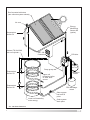
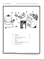
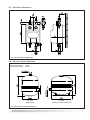
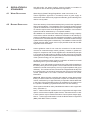
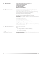
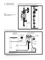
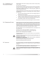
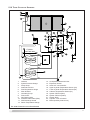
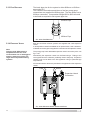
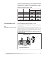
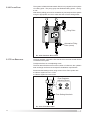
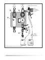
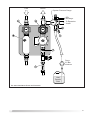
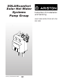
SOLARcomfort
Solar Hot Water
Systems
Pump Group
Instructions for Installation
and Servicing
LEAVE THESE INSTRUCTIONS WITH THE
END USER
Country of Destination GB/IE
TABLE OF CONTENTS
1.
1.1
1.2
1.3
1.4
1.5
1.6
GENERAL INFORMATION ................ 2
GUARANTEE .......................................... 2
SYSTEM CONTENTS ................................ 2
SYSTEM INSTRUCTION BOOKS ................... 2
SOLARCOMFORT .................................. 3
LIFESTYLE ............................................. 3
HOW THE SYSTEM WORKS ....................... 3
2.
SAFETY ............................................. 6
3.
3.1
3.2
3.3
3.4
TECHNICAL DATA ............................. 7
TEMPERATURE/PRESSURE ........................ 7
COMPONENT LIST ................................... 8
PUMP GROUP DIMENSIONS ...................... 9
EXPANSION VESSEL DIMENSIONS ............... 9
4.
4.1
4.2
4.3
4.4
4.5
4.6
4.7
4.8
4.9
4.10
REGULATIONS & STANDARDS...... 10
WATER REGULATIONS ........................... 10
BUILDING REGULATIONS ......................... 10
GENERAL GUIDANCE ............................. 10
BRITISH & EUROPEAN STANDARDS .......... 11
UK REGULATIONS (WATER HEATING) ...... 11
UK REGULATIONS (CONSTRUCTION) ........ 11
EU DIRECTIVES ................................... 12
OTHER PUBLICATIONS ........................... 12
ELECTRICAL CONNECTION ...................... 12
THERMAL INSULATION ............................ 12
5.
5.1
5.2
5.3
INSTALLATION ................................ 13
FITTING FLOW LIMITER .......................... 13
POSITIONING PUMP GROUP .................... 13
CONSIDERATIONS FOR POSITIONING PUMP
GROUP ............................................... 14
PIPEWORK AND FITTINGS ....................... 14
INSULATION .......................................... 14
SIZING OF PIPES .................................. 15
PIPEWORK ........................................... 15
ELECTRICAL CONNECTIONS .................... 15
TWO COLLECTOR SCHEMATIC ................. 17
THREE COLLECTOR SCHEMATIC .............. 17
WALL MOUNTING MODULES ................... 18
CONNECTING PIPEWORK ........................ 19
PIPE REDUCERS .................................. 20
EXPANSION VESSEL .............................. 20
PRESSURE RELIEF VALVE ...................... 21
FILLING POINT ..................................... 22
FLOW REGULATOR ................................ 22
5.4
5.5
5.6
5.7
5.8
5.9
5.10
5.11
5.12
5.13
5.14
5.15
5.16
5.17
6.
COMMISSIONING SYSTEM ........... 23
6.1 PRE-FILL CHECK .................................. 23
6.2 FLUSHING AND FILLING THE SYSTEM USING
GLYCOL .............................................. 24
6.3 FLUSHING THE SYSTEM USING WATER ...... 26
6.4 FILLING AND TOPPING UP THE SYSTEM WITH
GLYCOL .............................................. 28
6.5 SYSTEM PRESSURE .............................. 30
6.6 COMMISSIONING SHEET ......................... 31
7.
MAINTENANCE SCHEDULE .......... 32
1
this will be page 1
1.
GENERAL
INFORMATION
This manual is an integral and essential part of the product. It should be
kept with the product.
Please read carefully the instructions and notes about SOLARcomfort
contained in this manual as they provide important information regarding
the safe installation of the Pump Group.
IMPORTANT
Failure to follow these instructions correctly may invalidate the
guarantee.
IMPORTANT
Solar domestic hot water heating systems must be installed to
comply with the current Building Regulations, British Standards
and any applicable local regulations.
1.1 GUARANTEE
The SOLARcomfort Pump Group is guaranteed for 2 years against
munufacturing defect - see terms and conditions of guarantee on back
page.
1.2 SYSTEM CONTENTS
The complete SOLARcomfort solar water heating system is supplied in
the following consignments:1. Ref. 800201
Collector
2. Ref. 3107024/5 Roof Fittings Kit
3. 3820011/2
System Components
4. 3820001
1.3 SYSTEM INSTRUCTION BOOKS
2
1 per box
1 cardboard tube
1 box
Tyfocor anti freeze heat transfer fluid
1 x 20l container
The following instruction booklets are supplied with a complete
SOLARcomfort solar water heating system:1.
SOLARcomfort Solar Hot Water Systems Collectors 2 & 3 Collector
Set.
Covers collector installation and plumbing connection.
Supplied in System Components box.
2.
SOLARcomfort Solar Hot Water Systems Pump Group 40/60.
Covers installation, plumbing connection, system filling, flushing and
commissioning.
Supplied in System Components box.
3.
Solar Controller AST100
Covers installation, wiring connection and User Instructions.
Supplied in System Components box.
1.4 SOLARCOMFORT
SOLARcomfort systems are highly efficient and provide cost savings on
the energy used for heating hot water wherever they are used in the UK.
However, the savings made will depend on local climate, installation
characteristics and the households use of hot water.
It is important that the SOLARcomfort system is correctly sized for the
local climate condition and the household’s domestic hot water
requirements.
1.5 LIFESTYLE
After installation of the SOLARcomfort system, changes to the
householders use of hot water will be beneficial. Simple changes such as
bathing in the evening instead of the morning, and putting automatic
washing machines on when free hot water is available by solar energy.
In addition, the timing of the dwelling’s boiler controls must be modified to
ensure the ‘hot water ON’ time is set so that the water temperature in the
cylinder is at a minimum by the start of the ‘solar day’.
1.6 HOW THE SYSTEM WORKS
See fig. 1.6A
The solar collectors are heated by the sun’s rays. The heat generated is
stored in a hot water storage cylinder e.g. an Ariston Primo twin coil stainless
steel cylinder. The AST 100 Solar Controller continually compares the
temperature of the water within the cylinder with the temperature of the
solar collectors.
Whenever the solar collectors are hotter than the water within the cylinder,
the controller switches on the system’s circulating pump. The temperature
differential between the collectors and the cylinder is set via the AST100
Solar Controller. The heat transfer fluid within the solar system is then
circulated through the collectors and the cylinder’s heat exchanger, heating
the cylinder in just the same way as a central heating boiler.
The cylinder typically has two coils (heat exchangers), the lower coil is
heated by the solar system, therefore solar is the primary heat source.
The upper cylinder is heated by an auxiliary heat source, typically a central
heating boiler, which is used to heat water when there is insufficient heat
generated by the solar system. The Ariston Primo twin cylinder also has
two immersion heaters making it suitable for electric only heating systems.
The SOLARcomfort system is a forced circulation sealed system and
therefore requires an expansion vessel and a pressure relief valve (PRV),
both supplied with SOLARcomfort.
The air separator with an integral air vent together with an automatic air
vent positioned at the highest point on the system ensures that the sealed
system remains free of air.
3
Roof mounted collectors
(two collector system shown)
Air vent
Energy
Monitoring
Sensor S4
(option)
Temperature
Sensor S1
Ariston ITSI 210/300
twin coil cylinder
AST 100
Controller
PR Valve
Pump group
Temperature
Sensor S3
Expansion
vessel
Upper coil
heated by boiler
or other heat
source
Temperature
Sensor S2
PRV discharge
vessel
Solar system
low level fill
point
Lower coil heated by
solar energy
FIG. 1.6A BASIC PRINCIPLES
4
Solar system
drain point
Flow
1.
2.
3.
4.
Insulated Cover
Flow from Solar Collectors
Flow Temperature Gauge
Flow Shut Off Valve
c/w non return valve -red Knob
5.
6.
7.
8.
9.
Air Separator
Manual Air Vent
Return to Solar Collectors
Return Temperature Gauge
Return Shut Off Valve
c/w non return valve -blue Knob
Return
10.
11.
12.
13.
14.
15.
16.
17.
18.
19.
20.
Circulating Pump
System Fill and Drain Point
Fill and Drain Shut Off Valve
Flow Limiter
Flow Limiter Adjustment Screw
Non-return Valve
Non-return Valve Shut Off
Expansion Vessel Connection
Pressure Relief Valve (PRV)
PRV Outlet
System Pressure Guage
FIG. 1.6B PUMP GROUP COMPONENTS
5
2.
SAFETY
WARNING
The pump group must be correctly fitted to the wall using the bracket
supplied. It should not be supported by the connecting pipework
alone.
WARNING
During operation and commissioning the temperature of the heat
transfer fluid within the system and collectors can reach temperatures
high enough to present a risk of scalding. Never loosen fittings or
open vents when the system is hot.
WARNING
TYFOCOR LS Heat Transfer Fluid.
Although non-toxic it should not be swallowed.
Refer to label on its container for storage and safety information.
A detailed technical specification is available from Ariston on request.
Caution
SOLARcomfort should be installed and commissioned by approved
contractors. Failure to do so may invalidate the warranty.
Caution
The pump group should be positioned so that it is inaccessible to children
and cannot be tampered with.
6
3.
TECHNICAL DATA
PUMP MODULE
Pipe connection
22mm
Reducers supplied
15mm
Pump type
15/40
Maximum operating pressure
Electrical Cable
0.6MPa
1.0mm² 3 core heat resistant flex 3093Y to 85°C
Cover
Moulded polystyrene
AIR SEPARATOR MODULE
Pipe connection
22mm
Reducers supplied
15mm
Maximum operating pressure
Cover
0.6MPa
Moulded polystyrene
EXPANSION VESSEL
2 & 3 collector systems
25l
Optional size (code 12002737)
35l
Maximum pressure
10 bar
Pre-charge pressure
2.5 bar
PRESSURE RELIEF VALVE
Setting
6 bar
Discharge
½” BSP - Ø15 pipe
HEAT TRANSFER FLUID
Type
Tyfocor LS
Use undiluted
3.1 TEMPERATURE / PRESSURE
100%
Weight
1.04kg/l
Frost protection
to -28°C
Operating pressure and
temperature must be within
the limits depicted by the
hatched area
Operating temperatures above
100°C as depicted by the
shaded area must be avoided
for continuous operation
FIG. 3.1A TEMPERATURE PRESSURE DIAGRAM
7
3.2 COMPONENT LIST
Listed below are all the components required to fit the pump group.
Item
Description
1
Pump Group
2
Flow Limiter Components (see 5.1)
3
Wall Mounting Bracket
1
4
Screw
1
5
Wall Plug
1
6
Expansion Vessel 25l standard (35l option)
1
7
Expansion Vessel Fixings
1
8
Flexible Connector
1
FIG. 3.2A PUMP GROUP COMPONENT LIST
8
Qty
1
1 set
3.3 PUMP GROUP DIMENSIONS
FIG. 3.3A PUMP GROUP DIMENSIONS
3.4 EXPANSION VESSEL DIMENSIONS
Maximum pressure
Pre-charge pressure
10 bar
2.5 bar
25 Litre
(standard)
35 Litre
(optional: code 12002737)
FIG. 3.4A EXPANSION VESSEL DIMENSIONS
9
4.
REGULATIONS &
STANDARDS
SOLARcomfort hot water heating systems should be installed in
compliance with the following standards and regulations.
4.1 WATER REGULATIONS
Water Supply (Water Fittings) Regulations 1999 / www.wras.co.uk
These regulations (bye-laws in Scotland) ensure a good supply of
wholesome water and that only approved materials, pipes and fittings are
used to convey water.
4.2 BUILDING REGULATIONS
These are statutory documents and take priority over all other regulations
and recommendations. The installation of an unvented hot water storage
cylinder is classified as a “Controlled Service” and Regulation G3 applies.
To meet the requirements of the Regulations, installation of an unvented
system should be undertaken by a “competent installer”.
All installations of unvented hot water storage systems having a capacity
of more than 15 litres should be notified to the relevant Local Authority by
means of a building notice or by the submission of full plans. It is important
to note that it is a criminal offence to install an unvented hot water storage
system without notifying the Local Authority. The installation of the unvented
cylinder and hot water system must comply with BS 6700 and the HSE
Legionella Code of Practice.
4.3 GENERAL GUIDANCE
Current guidance notes do not cover the connection of a solar thermal
circuit to an unvented storage vessel (cylinder). However, if guidance is
sought for compliance with current regulations the fundamental principle
is to provide a fail-safe means of shutting off the solar input to the heat
exchanger if the cylinder temperature should rise above the set temperature
of the cylinder’s energy cut out. (See Note 1).
As with all unvented hot water systems, notification of intention to install
should be given to your local building control.
Option A. A non self-resetting mechanical shut-off should be installed on
the solar primary flow to the cylinder. The mechanical shut-off should be
suitable for use with a solar primary circuit (i.e. high temperature and glycol
resistant). The mechanical shut-off should be integrated electrically with
the cylinder energy cut out/s and if necessary the solar circuit temperature
control, please refer to the solar controller manufacturer for further
information.
Option B. Where the solar controller and hydraulic system demonstrate
that by no lesser means the requirement in Option A is satisfied by other
means; certification by an approvals body is required to demonstrate that
in the event of the stored water going over temperature, the heat input to
the cylinder is isolated by physical means and is non self-resetting.
These systems should be clearly identified with reference to the approvals
body. (See Note 2).
Note 1 : Whilst most solar cylinders use a coil type heat exchanger other
options such as external plate to plate devices, external annulars or ‘tank
in tank’ systems may be used but the same control options always apply.
Note 2 : Current approved bodies include the British Board of Agrèment
(BBA), WRc-NSF Limited, or KIWA.
10
4.4 BRITISH & EUROPEAN
STANDARDS
Connection of thermal solar heating systems
EN 12976: Thermal solar heating systems and their components
(prefabricated systems).
ENV 12977: Thermal solar heating system and their components (bespoke
systems).
BS5918: Latest version: Solar heating systems for domestic hot water.
Installation and equipment of DHW cylinders
BS5546: 2000 Specification for installation of hot water supplies for domestic
purposes, using gas-fired appliances of rated input not exceeding 70 kW.
BS6700: 1997 Specification for design, installation, testing and
maintenance, of servicing, supplying water for domestic use within buildings
and their curtilages.
The local water company by-laws.
Electrical connection
Current IEE wiring regulations.
Health and Safety document No 635 (Electricity at Work Regulations)
4.5 UK REGULATIONS
PARTICULARLY RELEVANT FOR
WATER HEATING EQUIPMENT
4.6 UK REGULATIONS
PARTICULARLY RELEVANT FOR
CONSTRUCTION
The Pressure Equipment Regulations (PED) 1999 - www.eurodyn.com
The Building Regulations (L1 A&B) 2006 and Domestic Heating Compliance
Guide - www.communities.gov.uk
The Building Regulations (P) 2005 - www.communities.gov.uk
Control of Substances Hazardous to Health Regulations (COSHH) 1994 www.hse.gov.uk
Further details available from: www.hse.gov.uk
Health & Safety At Work Act (HSW) 1974
Work at Height Regulations 2005.
Reporting of Injuries, Diseases and Dangerous Occurrences Regulations
(RIDDOR) 1995.
Management Health & Safety at Work Regulations (MHSWR) 1999.
Noise at Work Regulations 1989.
Construction (Health, Safety & Welfare) Regulations (CHSWA) 1996.
Electricity at Work Regulations 1989.
Construction Regulations (Head Protection) 1989.
Control of Substances Hazardous to Health Regulations (COSHH) 1994.
Construction (Design and Management) Regulations (CDM) 1994.
Personal Protective Equipment at Work Regulations 1992.
Lifting Operations and Lifting Equipment Regulations (LOLER) 1998.
Confined Spaces Regulations 1997.
Manual Handling Operations Regulations 1992.
The Workplace (Health, Safety and Welfare) Regulations 1992 (WHSWA).
Provision and Use of Work Equipment Regulations (PUWER) 1998.
Health and Safety (First Aid) Regulations 1981.
LZC - Low or zero carbon energy sources: strategic guide.
11
4.7 EU DIRECTIVES
Further details available from: www.europa.eu.int
Construction Directive: 89/106/EEC
Electromagnetic: 89/336/EEC
Low voltage: 73/23/EEC
Machinery Directive: 98/37/EC
4.8 OTHER
Preventing hot water scalding in bathrooms: using TMVs (IP 14/03).
DTI testing of solar systems (SP300275 1-3).
Review of issues related to active solar heating systems (SP300246).
Active solar performance and data review (SP300270).
Solar heating systems for hot water (BS 5918).
Hard water scale in hot water storage cylinders (IP13/93).
Heating systems in buildings – design for water-based heating systems
(PrEN 12828).
Building log books (GPG 348).
Solar heating (CIBSE DBSP WGG).
Sun in Action II (ESTIF – Sun in Action II).
Minimising the risk of legionnaires’ disease (TM 13).
BRE Digest 489.
Energy Saving Trust - www.est.org.uk
CE131 Solar Water Heating Systems - Guidance for professionals,
conventional indirect models.
PUBLICATIONS
4.9 ELECTRICAL CONNECTION
BS7671 2001 Amended 2004
APD P:
P1 - Design, Installation, Inspection and Testing
P2 - Provision of information
4.10 THERMAL INSULATION
Thermal Insulation Standard TIMSA (Thermal Insulation Manufacturers
and Suppliers Association).
12
5.
INSTALLATION
5.1 FITTING FLOW LIMITER
A flow limiter set is supplied separately, this must be fitted to the pump
group on the suction side of the pump as shown in fig. 5.1a.
Note:
The flow limiter is supplied with
fittings for 15Ø pipe.
15Ø
FIG. 5.1A FITTING FLOW LIMITER
5.2 POSITIONING PUMP GROUP
To Collector
Temperature
Sensor S1
From Collectors
To Collectors
AST 100
Controller
Expansion
Vessel
Cylinder
S3
Fill point
Pump
Group
S2
PRV
discharge
vessel
FIG. 5.2A SUGGESTED LOCATION
13
5.3 CONSIDERATIONS FOR
POSITIONING PUMP GROUP
The pump group and should normally be wall mounted in close proximity
to the cylinder.
Fig. 5.2A gives a typical layout.
The AST100 Solar Controller should be positioned so that the householder
has easy access with good visibility of the display. Also, consideration has
to be given to routing for connection to the pump group, cylinder and
collector temperature sensors.
Cables supplied with the sensors and control unit are nominal length and
Consideration should be given to the following when selecting a position
for pump group:1.
The pump group should be placed close to the storage cylinder to
keep pipe runs to a minimum.
2.
The pump group and pipework should have easy access with good
visibility for changing settings and all necessary maintenance work.
3.
The pump group and controller should be positioned so that they are
inaccessible to children and cannot be tampered with.
may require terminal boxes and extra cable lengths to make connections.
5.4 PIPEWORK AND FITTINGS
Taking into account the heat transfer fluid within the system may reach
high temperatures, the primary circuit should be copper, stainless steel
(rigid and flexible) or carbon steel braided high temperature hose. Pipe
joints and connections with other system components should also be able
to withstand the working temperatures and pressures. Thought should be
given to preventing corrosion due to dissimilar metals in contact.
All copper pipework must be Kite Marked BS EN1057 1996 Table X half
hard copper tube.
All fittings must be quality brass BS864-2 compression type.
Brass olives are recommended as they produce a better seal.
Brazed or silver soldered joints are acceptable.
The use of joint compounds such as ‘Fernox White’ is recommended for
compression joints.
Owing to the high temperatures of the solar system, plastic pipe and
fittings must not be used.
All fittings and components fitted must be able to withstand
temperatures in excess of 150°.
Soldered and push fit fittings should not be used.
Galvanised steel pipe should not be used.
5.5 INSULATION
All external pipework, connections and fittings must be insulated with
suitable high temperature, vermin resistant and UV resistant insulating
materials.
All internal pipework (excluding pipework to the expansion vessel) must
be insulated with suitable high temperature insulating materials.
Insulation of the pipework must only be undertaken after tightening
of the compression fittings and completion of a pressure test - see
section 6.
14
5.6 SIZING OF PIPES
The flow rate in the circuit is between 0.5 and 1.5 litres/min for each collector.
The flow velocity in the circuit should not exceed 1.5m/sec otherwise the
the system may be noisy during operation.
As a guide only: systems with total pipework of less than 50 metres, 15mm
diameter pipe should allow flow conditions to be met for systems with up
to four collectors.
When the total pipework is over 50 metres, then 22mm pipe should be
used.
An assessment of the specific installation requirements must be
undertaken.
5.7 PIPEWORK
5.8 ELECTRICAL CONNECTIONS
The installation of pipework must be made in accordance with good
plumbing practice, the following points should be considered when installing
pipework.
1.
Pipe runs should be chosen to give the shortest most direct route to
the storage cylinder, with minimum bends. Tight bends should be
avoided.
2.
The falls of pipes should be arranged to allow the system to be drained
and vented.
Low points, when unavoidable, should be fitted with a drain.
High points, when unavoidable, should be fitted with a vent.
3.
Where possible, all pipe runs should have a continuous slight incline
up to the highest point in the system to allow for natural venting of air
from the system.
4.
The automatic air vent supplied with the system should be fitted to
the highest point i.e. near the flow connection of the collectors.
5.
Adequate support and fixing should be provided for all pipework to
ensure that inclines are maintained and sagging is prevented.
6.
Owing to the high temperature differentials within the solar circuit
consideration should be given to the expansion of the pipework, expect
up to 12mm on a 5 metre run. Pipes should be fitted with brackets
and devices that allow for expansion and contraction, rigid fixings
should be avoided.
7.
A drain point must be fitted at the lowest point of the solar circuit. It
must be positioned at the down side of the non-return valve to ensure
the system can be fully drained.
All electrical connections must comply with current IEE Regulations.
The Pump is the only electrical connection for the Pump Group. This is
connected to the AST100 Controller’s R1 terminals via the cylinder manual
reset thermostat (thermal overload), refer to wiring diagram in the AST100
Solar Controller instructions.
1.
2.
3.
4.
5.
6.
The pump must be connected using 1.0mm² 3 core heat resistant 3
core flex 3093Y marked at least to tolerate 85°.
All cable sheath clamps must be correctly fitted.
The conductor sheath must be continuous into joint enclosures.
Conductors must be correctly fastened to terminals.
Conductor insulation to be within 2mm of terminals
All cable conductors external to joint enclosures must be insulated
and sheathed.
15
5.9 TWO COLLECTOR SCHEMATIC
Cylinder
1.
2.
3.
4.
5.
6.
7.
8.
9.
10.
11.
12.
Collector
System Pressure Guage
Pump Group
Automatic Air Vent
Flow Temperature Gauge
Shut Off Valve
Circulating Pump
Flow Limiter
Non-Return Valve
Pressure Relief Valve (PRV)
PRV Discharge Vessel
Return Temperature Gauge
FIG. 5.9A TWO COLLECTOR FLOW DIAGRAM
16
13.
14.
15.
16.
17.
18.
19.
20.
21.
22.
23.
Air Separator with Manual Air Vent
Expansion Vessel
Solar AST 100 Controller
Upper Cylinder Temperature Sensor (S3)
Lower Cylinder Temperature Sensor (S2)
Collector Temperature Sensor (S1)
System Fill Point (flow)
System Fill Point (return)
System Drain
Cylinder - twin coil shown
Boiler (auxiliary heat source)
5.10 THREE COLLECTOR SCHEMATIC
Cylinder
1.
2.
3.
4.
5.
6.
7.
8.
9.
10.
11.
12.
Collector
System Pressure Guage
Pump Group
Automatic Air Vent
Flow Temperature Gauge
Shut Off Valve
Circulating Pump
Flow Limiter
Non-Return Valve
Pressure Relief Valve (PRV)
PRV Discharge Vessel
Return Temperature Gauge
13.
14.
15.
16.
17.
18.
19.
20.
21.
22.
23.
Air Separator Manual Air Vent
Expansion Vessel
Solar AST 100 Controller
Upper Cylinder Temperature Sensor (S3)
Lower Cylinder Temperature Sensor (S2)
Collector Temperature Sensor (S1)
System Fill Point (flow)
System Fill Point (return)
System Drain
Cylinder - twin coil shown
Boiler (auxiliary heat source)
FIG. 5.10A THREE COLLECTOR FLOW DIAGRAM
17
5.11 WALL MOUNTING MODULES
See fig. 5.11A
The pump module is supplied with a wall bracket. The pump group must
be correctly fitted to the wall using the bracket supplied. It should not be
supported by the connecting pipework alone.
FITTING PROCEDURE
1.
Determine the best location for the pump group, take into consideration
the following:i Access for fill and drain.
ii Position of the expansion vessel.
iii Position of the PR Valve.
iv Provision has to be made for the discharge of the PR Valve
to be collected in a suitable container.
v Ease of plumbing to cylinder and collectors.
2.
Mark position for mounting bracket.
3.
Drill one holes for wall plug (if used).
4.
Screw on bracket to wall and level.
5.
Mount pump group onto bracket as shown in fig. 5.11a.
6.
Tighten Locknuts
Wall Plug
Bracket
Lock Nut
Lock Nut
Bracket
FIG. 5.11A MOUNTING PUMP GROUP
18
5.12 CONNECTING PIPEWORK
Automatic Air Vent
Shut Off
valve
Pipes Ø15mm or Ø22mm
see 5.%
C
PR Valve
A
Expansion Vessel
D
B
PR Valve relief
plumbed to low level
Ø15mm
PRV discharge
vessel
Flow
C
Return
A
System Drain
D
FIG. 5.12A CONNECTING PIPEWORK
B
19
5.13 PIPE REDUCERS
The basic pipe size for the system is either Ø22mm or Ø15mm see section 5.5.
The collectors connections and three of the four pump group
connections are supplied for Ø22mm pipe. The flow limiter has a
Ø15mm connection. Compression fittings Ø22 to Ø15 will need
to be fitted as required to suit system pipe size.
Ø15mm Pipe
Ø22mm Pipe
FIG. 5.13A PIPE REDUCERS
5.14 EXPANSION VESSEL
Note:
Owing to high differentials in
temperature within the solar
circuit and the use of water/glycol
mixture, expansion vessels are
larger than comparable heating
systems.
Both two and three collector systems are supplied with a 25l expansion
vessel.
A 35l expansion vessel is available as an optional extra, code: 12002737.
A flexible connection pipe is supplied for connection of the expansion vessel.
The pump group has a dedicated expansion vessel connection point -see
fig. 5.14A.
Alternatively the expansion vessel can be fitted using a T fitting to the
return pipework to the collectors, preferably close to the pump. Expansion
vessels must not be fitted to the flow pipework owing to potential high
temperatures.
No manual isolation valves are permitted in the pipework to the expansion
vessel.
Flow
Return
Expansion Vessel
Connection
FIG. 5.14A EXPANSION VESSEL CONNECTION POINTS
20
The chart below gives the initial pressure charge that the expansion vessel
will require for a given system height (static system head).
The expansion vessel should be charged to this pressure prior to filling
the system.
The factory set pressure of vessels is 2.5 bar.
System height
5.15 PRESSURE RELIEF VALVE
(metres)
System filling
pressure
(metres)
3 to 1 0
Pre-pressure of Expansion Vessel
2 5 l Ve s s e l
3 5 l Ve s s e l
1 .5
1 .3
1 .4
11
1 .6
1 .4
1 .5
12
1 .7
1 .5
1 .6
13
1 .8
1 .6
1 .6
14
1 .9
1 .7
1 .7
15
2 .0
1 .8
1 .8
s ta n da r d
o ptio n a l
A Pressure Relief Valve (PRV) is supplied with the system.
The pump group has a dedicated PRV connection point -see fig. 5.15A.
Note:
The PR valve is factory set at 6bar.
Alternatively the PRV can be fitted to any part of the system using an
appropriate T fitting.
The PRV discharge should be plumbed to a low level and terminated inside
a suitable container to collect any discharged heat transfer fluid. The
discharge and container should be inside the dwelling normally under the
pump group - see figs. 5.1A and 5.15A.
No manual isolation valves are permitted in the pipework to the PRV or in
the PRV discharge pipe.
Pressure Relief Valve
PRV
Discharge
FIG. 5.15A PRESSURE RELIEF VALVE
21
5.16 FILLING POINT
The system is filled with heat transfer fluid, this is pumped into the system
via a filling point. The pump group has dedicated filling points - see fig.
5.16A.
Alternatively a filling point can be created at any low level part of the system
using an appropriate non return valve and shut-off valve arrangement.
Filling Point
Alternative Filling
Point (return)
FIG. 5.16A PRESSURE RELIEF VALVE
5.17 FLOW REGULATOR
The flow regulator controls the flow rate at which the heat transfer fluid is
circulated in the system.
To adjust the flow, turn the adjusting screw.
The flow rate should be set to suit the number of collectors, the cylnder’s
heat exchanger surface area and specific installation requirements.
Recommended settings when using Ariston Primo Twin cylinder are:2 Collector system 0.5 to 1.7 l/min
3 Collector system 0.5 to 2.6 l/min
Flow Regulator
Adjusting Screw
Flow Setting Litres/min
FIG. 5.17A FLOW ADJUSTMENT
22
6.
COMMISSIONING
SYSTEM
6.1 PRE-FILL
CHECK
IMPORTANT
All fittings used must be suitable
for temperatures in excess of
150°C.
Flushing and commissioning should only be carried out when:1. No sun is shining on the collectors e.g. early in the morning,
evening or when the collectors are covered.
2. Temperatures are not near freezing or there no is risk of frost.
Before filling the system carry out the following pre-fill check.
1. Check collectors have been fitted correctly.
2. Check all roof tiles are replaced and secure.
3. Check weatherproofing of roof access pipework.
4. Check all pipework connections are correct and fully tightened.
5. Check all pipework is fully supported.
6. Check all manual air vents are closed.
7. Check automatic air vents are open.
8. Check isolation valve to automatic air vent is open.
9. Check expansion vessel connection and that the pipework to it is
free from any valve or restriction.
10. Check pressure relief valve is correctly fitted.
11. Check PRV discharge is fitted correctly and that a suitable collecting
vessel is in place.
12. Check that the indirect cylinder has been filled.
13. Check that there are no valves or restrictions in the PRV discharge.
14. Check connections to the cylinder.
15. Check that an automatic air vent is fitted at the highest point in the
system, this will normally be adjacent to the collector flow.
16. Check that any high points/potential air traps in the pipework are
fitted with a suitable automatic air vent.
17. Check drain points are closed.
18. Open all isolating valves within the circuit.
19. Check the pre-pressure of the expansion vessel - see 5.12.
20. Check equipotential bonding is fitted where required.
21. The pump is correctly wired and earthed.
22. Check all wiring is to current IEE regulations and BS7671.
23
6.2 FLUSHING AND FILLING THE
SYSTEM USING GLYCOL
To remove any contaminants, the solar system has to be flushed with heat
transfer fluid or water prior to final filling, for water flush see 6:3.
Flushing and filling with glycol is done using a suitable electric pump or
hand pump which should be able to provide pressure up to 3.5 bar.
Flushing Procedure using glycol - refer fig. 6.2A
IMPORTANT
The indirect cylinder MUST be fully
filled before filling the solar circuit.
Failure to do so may result in
irreparable damage to the cylinder.
1.
2.
3.
4.
5.
6.
7.
8.
IMPORTANT
Tyfocor LS heat transfer fluid is premixed and must not be further
diluted.
9.
10.
11.
12.
13.
14.
15.
16.
17.
18.
19.
20.
21.
22.
23.
24.
24
Carry out the pre-fill check - see 6.1.
Remove pump group cover.
Connect fluid flow pipe to fill connection A.
Connect return flushing pipe to connection B.
Open valves C then D.
Open non-return valve shut off E.
Check the flow shut off valve with integral temperature guage F is
open, the red housing should be vertical (90°CW) as shown.
Check the return shut off valve with integral temperature guage G is
open, the blue housing should be vertical (90°CW) as shown.
Set Flow Rate to maximum H (slot vertical) - see 5.16.
Close air bleed valve J.
Open the air vent(s) at the system high point(s).
Start pumping fluid through the system. As the pumped fluid will
take the route of less resistance it will flow through the pump and
then return to the container.
After a short period close the ball valve G by turning the blue
thermometer housing (CCW). This will divert the flow in the normal
direction of the system.
When flushing is complete close valve C (flush return). The system
will now start to fill. Fill the system slowly to encourage air to escape.
Raise the system pressure to 3.5 Bar to improve air removal and to
check all connections are sound.
Switch off filling pump, close valve D and remove filling pipe.
Check air bleed valve J for air.
Check system for leaks.
Return system pressure to the required ‘system fill pressure’ as
shown on chart 6.5.
Ensure the non-return valves, flow limiter, all ball valves and other
shut off devices are returned to their correct position.
When all air has been evacuated from the system close the automatic
air vent and associated isolation valves.
Set Flow Rate at H to 1l/min - see 5.16.
Refit pump group cover.
Replace all thermal insulation and ensure all external and internal
pipework and fittings are suitably insulated - see 5.4.
Flow
Return
System Pressure Gauge
PRV
Discharge
To Expansion
Vessel
Pump
3.5 Bar
minimum
Heat
Transfer
Fluid
FIG. 6.2A PUMP GROUP FLUSHING (GLYCOL) AND FILLING
25
6.3 FLUSHING THE SYSTEM USING
WATER
IMPORTANT
The indirect cylinder MUST be fully
filled before filling the solar circuit.
Failure to do so may result in
irreparable damage to the cylinder.
To remove any contaminants, the solar system has to be flushed with heat
transfer fluid or water prior to final filling, for glycol flushing and filling see
6:2.
Flushing and filling with water can be done using a conventional filling loop
from the mains supply. The mains pressure must be capable of pressurising
the system to 3.5 bar.
If 3.5 Bar is not achievable from a filling loop a suitable electric pump or
hand pump which should be used.
Flushing Procedure using water - refer fig. 6.3A
IMPORTANT
After the system has been flushed
with water it must be completely
drained of water before filling with
glycol to ensure the glycol fill is of
the correct concentration.
1.
2.
3.
4.
5.
6.
7.
8.
9.
10.
11.
12.
13.
14.
15.
16.
17.
18.
19.
20.
21.
22.
23.
24.
26
Carry out the pre-fill check - see 6.1.
Remove pump group cover.
Connect one end of the water flow pipe to fill connection A, the other
end is either connected to a mains filling point, or to a pump
arrangement.
Connect return flushing pipe to connection B, the other end either
goes to a drain or suitable collector.
Open valves C then D.
Open non-return valve shut off E.
Check the flow shut off valve with integral temperature guage F is
open, the red housing should be vertical (90°CW) as shown.
Check the return shut off valve with integral temperature guage G is
open, the blue housing should be vertical (90°CW) as shown.
Set Flow Rate to maximum H (slot vertical) - see 5.16.
Close air bleed valve J.
Open the air vent(s) at the system high point(s).
Open filling loop or start pumping water through the system. As the
pumped water will take the route of less resistance it will flow through
the pump and then return to the drain or container.
After a short period close the ball valve G by turning the blue
thermometer housing (CCW). This will divert the flow in the normal
direction of the system.
When flushing is complete close valve C (flush return). The system
will now start to fill. Fill the system slowly to encourage air to escape.
Raise the system pressure to 3.5 Bar to improve air removal and to
check all connections are sound.
Stop pump or shut off filling loop (as applicable).
Check air bleed valve J for air.
Check system for leaks.
Return system pressure to the required ‘system fill pressure’ as shown
on chart 6.5.
Shut off valve D, then disconnect filling pipe.
Allow as much water as possible to drain from the system through
valve C, then shut off valve C and disconnect drain pipe.
Drain ALL the remaining water out of the system by opening the
system drain point/s at the lowest part of the system.
When ALL water has been drained close drain points.
Fill system with glycol - see 6.4.
Flow
Return
System Pressure Gauge
PRV
Discharge
To Expansion
Vessel
Filling loop
Mains
3.5 Bar
minimum
Pump
3.5 Bar
minimum
Water
FIG. 6.3A PUMP GROUP FLUSHING (WATER) AND FILLING
27
6.4 FILLING AND TOPPING UP THE
SYSTEM WITH GLYCOL
To remove any contaminants the solar system must be flushed with heat
transfer fluid (glycol) or water prior to final filling. For glycol flushing and
filling see 6:2, for water flushing see 6.3.
Filling with glycol is done using a suitable electric pump or hand pump
which should be able to provide pressure up to 3.5 bar.
IMPORTANT
The indirect cylinder MUST be fully
filled before filling the solar circuit.
Failure to do so may result in
irreparable damage to the cylinder.
IMPORTANT
After the system has been flushed
with water it must be completely
drained of water before filling with
glycol to ensure the glycol fill is of
the correct concentration.
Filling and Topping Up Procedure - refer fig. 6.4A
1.
2.
3.
4.
5.
6.
7.
8.
9.
10.
11.
IMPORTANT
Tyfocor LS heat transfer fluid is premixed and must not be further
diluted.
12.
13.
14.
15.
16.
17.
18.
19.
20.
28
Connect fluid flow pipe to fill connection A.
Remove pump group cover.
Open valve B.
Check non-return valve shut off is open C.
Check the flow shut off valve with integral temperature guage D is
open, the red housing should be vertical (90°CW) as shown.
Check the return shut off valve with integral temperature guage is
open, the blue housing E should be vertical (90°CW) as shown.
Set Flow Rate to maximum F (slot vertical)- see 5.16.
Close air bleed valve G.
Open the air vent(s) at the system high point(s).
Start pumping fluid into system, fill the system slowly to encourage
air to escape.
Raise the system pressure to 3.5 Bar to improve air removal and to
check all connections are sound.
Switch off filling pump, close valve B and remove filling pipe.
Check air bleed valve G for air.
Check system for leaks.
Return system pressure to the required ‘system fill pressure’ as shown
on chart 6.5.
Ensure the non-return valves, flow limiter, all ball valves and other
shut off devices are returned to their correct position.
When all air has been evacuated from the system close the automatic
air vent and associated isolation valves.
Set Flow Rate at F - see 5.16.
Refit pump group cover.
Replace all thermal insulation and ensure all external and internal
pipework and fittings are suitably insulated - see 5.4.
Flow
Return
System Pressure Gauge
PRV
Discharge
To Expansion
Vessel
Pump
3.5 Bar
minimum
Heat
Transfer
Fluid
FIG. 6.4A PUMP GROUP FILLING AND TOPPING UP
29
6.5 SYSTEM PRESSURE
System
geodetic
30
2 Collector
3 Collector
2 5 l Vessel
3 5 l Vessel
height
System
filling
pressure
metres
Bar
Bar
Bar
3 to 1 0
1 .5
1 .3
1 .4
11
1 .6
1 .4
1 .5
12
1 .7
1 .5
1 .6
13
1 .8
1 .6
1 .6
14
1 .9
1 .7
1 .7
15
2 .0
1 .8
1 .8
Pre-pressure of Expansion Vessel
✓
6.6 SOLARCOMFORT - COMMISSIONING SHEET
Pre-filling checks completed
Flushing and system filling checks completed
Electrical controls operating correctly
All safety devices operate correctly
All temperature sensors operate correctly
Anti-scald prevention in place
Debris removed and site left clean
User instructions explained and handed over
Installation and maintenance instructions left on site
System schematic handed over
De-commissioning details handed over
Collector 1 Serial Number
✎
Collector 2 Serial Number
Collector 3 Serial Number
System Volume
litres
Heat transfer fluid type
Heat transfer fluid mix
%
System pressure when cold
Bar
Differential temperature ‘ON’ temperature
°C
Differential temperature ‘OFF’ temperature
°C
Expansion vessel pressure
Bar
Flow rate
l/min
Commissioned by:
Accepted by:
Signed:
Signed:
On behalf of:
Date:
Date:
31
7. MAINTENANCE
SCHEDULE
SOLARCOMFORT - ANNUAL MAINTENANCE SCHEDULE
✓
1.
Check the system pressure when cold against commissioned tolerances.
2.
Check the expansion vessel pressure against commissioned tolerances.
3.
Check the pH level of the heat transfer liquid. Tyfocor LS must be in the range 9 -10.5
4.
Check the refraction index. Tyfocor LS must be in the range 1.380 – 1.384
5.
Check using refractometer that heat transfer fluid is of sufficient concentration for -28°C
6.
Check Collector glazing is undamaged.
7.
Check Collector glazing is reasonably clean.
8.
Check, where visible, absorber paintwork or coating is sound.
9.
Check the roof fixings are firm and the roof covering satisfactory by visual inspection.
10.
Check electrical controls and temperature sensors are operating sensibly.
11.
Check the circulating pump is operating without due noise.
12.
Check pipework insulation is firmly in place.
13.
Check there are no condensation or damp spots, particularly around the pipework and fixings in
the roof space.
14.
Check all safety and information labels are in place.
15.
The antifreeze should be tested at least every five years (depending on the type chosen).
16.
Regular de-scaling may be required for the heat exchanger surfaces.
17.
If there is a significant drop in primary pressure or fluid level, suspect one or more of the following:1. Overheating - fluid displacement via safety discharge
2. Leak on system or poor design.
3. Expansion vessel requires priming
N.B. For detailed fault finding see AST 100 Solar Controller Manual
32
TERMS AND CONDITIONS OF GUARANTEE
The SOLARcomfort Pump Group is guaranteed for 2 years.
Please read these terms and conditions which are in addition to any terms and
conditions detailed in this book or any registration card supplied with your
appliance.
SOLARcomfort solar thermal systems must only be installed and
commissioned by Ariston trained and approved installers. Failure to comply
with this requirement will invalidate the warranty.
A charge will be made to the owner of the appliance if:1.
The reason for any service visit is as a direct result of a failure to install the
appliance in accordance with the manufacturer’s instructions.
2.
Your installer does not complete the necessary commissioning process
and procedure as detailed in the Installation and Operating Instruction manuals.
3.
Your appliance is not serviced on or before the 12 month anniversary of
installation.
4.
Our service engineer calls as requested and the failure is a nonmanufacturing defect.
Failure to pay an invoice for any such occurrence will be assumed by MTS that
you accept that your appliance has not been installed correctly and understand
that any manufacturer’s guarantee has been withdrawn.
On the 12 month anniversary of the appliance installation, you must have it serviced
to continue any guarantee offered into the following year. Failure to do so will
invalidate your guarantee and should an MTS engineer be required to attend and
no proof of service documentation is made available, then MTS will charge.
If you have a problem with commissioning on installation, please contact our
Technical Department on 0870 241 8180.
Tel.:- 01494 755600
Fax:- 01494 759775
www.mtsgroup.com/uk
email: [email protected]
Technical Service Hot Line 0870 241 8180
Customer Service Help Desk 0870 600 9888
Solar Hot Water Systems
Pump Group Manual 06/02/2007
MTS (GB) Limited
MTS Building
Hughenden Avenue
High Wycombe
Bucks HP13 5FT