1
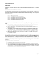
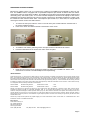
Fitness Entertainment Solutions
900 MHz Analog Receiver
Manual and User Guide
ARG-OM-012 Rev B
Audio Resource Group, Inc. • 405 Main Ave W, Unit 4G • West Fargo, ND 58078 • ©2013 Audio Resource Group, Inc. • All Rights Reserved •
www.argaudio.com
CONTROL FUNCTIONS:
The buttons on the receiver perform the functions as detailed below:
1.
2.
3.
4.
5.
CHANNEL UP Button
CHANNEL DOWN Button
VOLUME UP Button
VOLUME DOWN Button
MUTE Button
6.
7.
8.
9.
10.
SET Button
SCAN Button
MEMO Button
C-SAFE Port
Auto Power ON/OFF and
3.5 mm Stereo Audio Jack
MOUNTING INSTRUCTIONS:
The ARG 900MHz receiver is a universal unit designed to be compatible with most makes and models of cardio
equipment. To mount the Receiver:
1.
2.
3.
4.
Determine the appropriate location to mount the receiver to the cardio equipment. Take note the
range of motion of the components of machine and make sure the placement of the receiver and its
cabling will not interfere with operation of the machine or any safety features.
Slide the cable ties through the appropriate holes in the mounting cleat on the underside of the
receiver. (Top to bottom if you are mounting it to a horizontal bar or side to side if you are mounting
to a vertical bar.)
Wrap and thread the cable ties around the bar on the cardio machine at the predetermined
location. Pull the ties tightly around the bar so the receiver does not move or rotate. Be careful not
to over-tighten the ties to avoid cracking the mounting cleat or case of the receiver. Trim off the
excess ends of the cable ties.
Connect the power cable to the receiver. The receiver can be powered by either a CSAFE power
outlet on the cardio machine or an A/C power converter that can be plugged into the wall/floor.
(Power adapters and cables are not included and must be ordered separately.) If you are using a
C-SAFE connection: connect one end of the Cat-5 cable to the C-SAFE port on the cardio
machine. (Check with the equipment manufacturer to make sure the machine has this feature and
for location of the outlet.) The other end of the cable connects to the RJ45 receptacle on the back
of the receiver. If you are using an A/C power supply: locate a standard 110V outlet and plug the
12V A/C adapter side into the outlet and the RJ45 plug into the receptacle on the back of the
receiver. Make sure to route the cord for either option appropriately to avoid interference with any
of the functions or safety features of the cardio machine!
Page 2
OPERATING INSTRUCTIONS:
POWER ON/OFF:
The receiver is powered on and off by inserting the headphone plug into the headphone jack. When you plug the
headphones in, the receiver will turn on. When you unplug the headphones, the receiver will turn off after a few
seconds.
SETTING UP AND PROGRAMMING THE CHANNELS:
The receiver has six “groups” of frequencies that are pre-programmed to channel numbers that correspond to the
frequency/channel pairs used by the various entertainment/fitness equipment manufacturers. These “groups” allow
you to directly interface with transmitters and receivers from other manufacturers. The “groups” match up to the
manufacturers as follows:
Group 1 – ARG’s Custom Channels
Group 2 – User programmable w/auto-scanning feature
Group 3 – Compatible with Cardio Theater (XTV-9T) products
Group 4 – Compatible with Cardio Theater (XTV-9TM) products
Group 5 – Compatible with MYE/Fantaay/True products
Group 6 – Compatible with BVe/Broadcast Vision products
The receiver comes preset to Group 1, the ARG custom channel grouping. If you need to change the
group/frequencies to be compatible with other manufacturer’s equipment, you can change the group number as
follows:
1.
2.
3.
4.
Press and hold the “VOLUME UP” and “MEMO” buttons at the same time for about four seconds until
the lock icon disappears and the small group number shows in the center of the display.
Using the “MUTE” button, choose the group number of the frequency/channel pairs you wish to use
based on the list above.
The “CHANNEL UP” and “CHANNEL DOWN” buttons allow you to view the channels available in that
specific group. Choose the channels you are using by pressing the “MEMO” button to enable/disable
the channels in the group. The channels with the word “MEMORY” showing in the display are enabled
and vice versa. For example: if you have three TV’s each one with its own transmitter, you would
enable channels 1, 2, and 3.
Return to normal “user” mode by pressing and holding the “VOLUME UP” and “MEMO” buttons together
for four seconds once again.
If you are going to select your own frequencies/channel pairs, you can do so by first using the previous process to set
the receiver to “group 2”. Leave the receiver in the programming mode to set-up your own frequency/channel pairs
that correspond to the frequencies you have set your transmitters to broadcast on. At this point you MUST have the
receiver perform an “auto-scan” to determine what frequencies are being used by the devices in your facility. The
receiver has to scan through all of the frequencies in the 900MHz bandwidth to “find” the frequencies that are in use
at your location. Before going through the “auto-scan” procedure, make sure that ALL of the transmitters in your
facility are: a) powered on, b) connected to a signal source, c) set to and broadcasting on your desired broadcast
frequencies.
Now, perform the “auto-scan” function as follows:
1.
2.
3.
Double check to make sure the receiver is in the “user” mode
Press and hold the MUTE and SCAN buttons for five seconds. This will put the receiver into “setting mode”
Start the auto-scan” process by pressing the “SCAN” button once. The receiver will now scan ALL the
frequencies in the 900MHz bandwidth. (902MHZ to 928MHz) Every time the receiver detects a signal, it will
store that frequency to a list of used frequencies that you will pair with channel numbers later. It takes about
two minutes for the receiver to complete the auto-scan process.
Page 3
When the auto-scan is complete, you are ready to assign preset channel numbers to the transmitter frequencies
being broadcast. This process is similar to and done for the same reason you pre-set car radio stations as it allows
for quick access to the channels you use without having to scan through the ones you don’t. The large number on the
left side of the display is the channel number. The smaller numbers on the right side of the display is the frequency
the receiver is tuned to.
1.
2.
3.
4.
To pair a frequency to a channel number, choose the channel number by pressing the “CHANNEL UP” or
“CHANNEL DOWN” button.
Scroll through the list of frequencies the receiver found in the auto-scan by pressing the “VOLUME UP” or
“VOLUME DOWN” button until you see the frequency you want associated with that channel number.
When you have the desired channel number/frequency pair showing together in the display, press and hold
the “MEMO” button until the word “Memory” flashes once on the screen. That channel number/frequency
pair is now stored as a “preset” in the memory of the receiver.
Repeat this process as needed so all of the frequencies being used by the transmitters in your facility are
assigned to a channel number and therefore are retained in the memory of the receiver.
For example, you have three TVs in your facility equipped with 900MHz transmitters; set to following frequencies:
902.250, 904.650, and 908.100.
1.
2.
3.
4.
To set the first channel number and frequency, select the channel number “01” with the “CHANNEL UP” or
“CHANNEL DOWN” buttons.
Scroll through the list of found frequencies with the “VOLUME UP” or “VOLUME DOWN” buttons until you
see “902.250”.
With “01” and “902.250” showing on the display, press and hold the “MEMO” button until “Memory” flashes
once on the screen. Channel number “01” is now paired to frequency “902.250” in the memory of the
receiver. Now select channel number “02” and frequency “904.650” as above and press and hold the
“MEMO” button until “Memory” flashes in the display.
Repeat the process for channel number “03” and Frequency “908.100”.
When you have entered all of the frequencies being used at your facility, press and hold the “SCAN” and “MUTE”
buttons together for 5 seconds to exit the setting mode. The “lock” icon will reappear and your receiver will now be in
the normal operating mode.
Note: The receiver will only save up to 64 frequencies in the memory and will stop auto-scanning when it collects the
64th frequency in the found list. If the receiver does not find all of the frequencies your transmitters are broadcasting
or if you are in an area with excessive noise or interference; you can adjust the scanning sensitivity of the receiver.
To adjust the sensitivity, press the “SET” button while in the setting mode. Each time you press the button the
sensitivity setting will advance by 1 class (16 total classes, 0 to F). The higher the number or letter, the less sensitive
the scan will be. The factory setting is 4. After you change the sensitivity setting, re-scan the frequencies so the
receiver can find those missed the first time. Reset the sensitivity and re-scan as necessary so the setting allows the
receiver to find all of the frequencies your transmitters are using.
SQUELCH SETTING:
The squelch setting adjusts the threshold at which audio signals will pass-through to the headphones. If there is
excessive low level noise (hiss or static) bleeding through into one of the channels, adjust the squelch control to block
the audio signal that passes through the circuit to the headphones. The higher the number, the more noise the
receiver will block. If the setting is too high, the receiver will start to block the desired portions of the audio signal as
well. The ideal setting is to adjust the level so all of the desired audio is heard but with as little background noise as
possible. To adjust the squelch setting: make sure the receiver is in the normal mode. Press and hold the “SET”
button for 3 seconds. (The channel number will change to the squelch setting, ranging from 0 to 9; the factory default
level is 3.) Press the “CHANNEL UP” or “CHANNEL DOWN” buttons to adjust. Press and hold the “SET” button again
to return to the normal mode.
RESETTING THE RECEIVER:
The receiver is equipped with built-in, self-protection circuitry that will activate when receiving a variety of electrical or
environmental circumstances. This may cause the unit to lock-up or behave in an undesirable fashion. If this occurs,
you can reset the receiver by disconnecting it from its power source for one minute. This will restart the software and
should return the unit to normal operation. If problems persist, please contact your dealer or ARG for further
assistance.
Page 4
HEADPHONE JACK REPLACEMENT:
Because it is subject to heavy use, it is normal for the contacts in the headphone jack assembly to wear out over
time. The 900MHz receiver is equipped with a replaceable headphone jack module to address this wear without
replacing the entire unit. Under ideal conditions, the headphone jack is rated to last roughly 6,000 plug insertions and
removals (cycles). After 6,000 cycles, an icon that looks like headphones will flash in the display to alert that the
headphone jack should be replaced. Every time the receiver is powered-up, the display will flash the number cycles
the module has used under the letters “UHF”. The headphone jack module can, in most cases, be changed without
removing the receiver unit from the cardio machine.
2.
To remove the worn jack, locate the “arrow” on the tab of the jack module located on the back side of
the receiver toward the bottom.
Press on the “arrow” and slide the module in the direction of the “arrow”.
3.
4.
To install the new module, guide the grooves of the jack module into the tabs of the receiver.
Push the module back into the receiver unit until it “clicks” into place.
5.
Reset the cycle count to zero by pressing and holding the “SET” and “CHANNEL UP” buttons at the
same time for 3 seconds or until the headphone icon stops flashing.
1.
LIMITED WARRANTY
Audio Resource Group, Inc. warrants all new ARG products to be free from defects in materials and manufacture for the warranty periods set forth
below. The warranty periods commence on the invoice dates of the original purchase. This warranty applies only against defects discovered within
the warranty period and notification to ARG must be given within 30 days after the date of discover of any nonconformity. Parts repaired or replaced
under the terms of this warranty will be warranted for the remainder of the original warranty period only. Product that fails after the warranty period will
be repaired or replaced at the current part and labor pricing after inspection by ARG and authorization from the customer. Audio Resource Group,
Inc.’s obligations under this warranty are limited as set forth below:
ARG-CV-900AR
ARG-CV-900AR
900 MHz Analog Receiver
900 MHz Analog Receiver
Purchased Prior to 2014
Purchased after 1/1/2014
1 Year
2 Years
Warranty only applies to the original buyer. Warranty is void if products have been damaged due to accident, misuse, abuse, improper service,
mechanical or electrical non-ARG, Inc. authorized modification. ARG, Inc. is not liable, without limitation to any person or entity, for any direct,
incidental, consequential damages or medical expenses caused by any use, defect, failure or malfunction of the product. This warranty does not cover
cosmetic damage of the product or if the serial number or model number affixed to the product has been removed, defaced, changed, altered or
tampered with. This warranty does not cover installation or signal reception problems. The terms of the warranty are governed by the laws of the state
of North Dakota, USA.
ARG will only accept returned products with prepaid shipping and a return authorization number. Contact ARG, Inc. at 888-468-4552 for a return
authorization number or for additional information.
Mail or Ship To:
Audio Resource Group, Inc.
Attn: Repair Department
405 Main Ave W Unit 4G
West Fargo, ND 58078
Phone: (888) 468-4552
Fax: (888) 373-4819
Email: [email protected]
Page 5