1
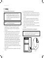
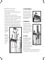
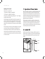
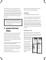
Plug & Play®
Aquarium
Red Sea MAX® C-Series
Complete Coral Reef Systems
Installation and Operation Manual
Red Sea MAX® C-Series
Complete Coral Reef Systems
Installation and Operation Manual
MAX C Installation & Operation Manual
Safety......................................................................2
Location...................................................................3
Unpacking the MAX® C system.................................4
Components............................................................5
Assembly.................................................................6
Installation of sump components..................................8
Installation of optional chiller................................13
Installation of lighting hood...........................................14
Operation of power center.....................................16
Initial fill..................................................................16
Operation of the protein skimmer..........................17
General aquarium maintenance.............................18
Trouble shooting.....................................................20
Warranty..................................................................22
用户手册
Congratulations on your purchase of the
Red Sea MAX® C-Series complete reef
system.
Red Sea developed the MAX® to provide a complete reef spec system
so that from the beginning, you can focus on the aquarium's inhabitants
rather than the hardware.
The Red Sea MAX® approach to the coral reef experience is to create
an environment that is specifically attuned to the needs of coral and
all reef inhabitants on an artificial reef. In the ocean coral reefs flourish
only where specific physical conditions prevail, such as sufficient light,
adequate current, stable temperature and water quality.
The Red Sea MAX® system provides the conditions that enable you to keep
a thriving, healthy reef in your own home.
This manual contains the installation and operational instructions for all of
the MAX® C-Series aquariums.
We hope that you enjoy your MAX® and wish you happy reefing.
To benefit from product update information and exclusive special offers to
registered MAX® owners, please register your MAX® on-line at redseafish.com
1
Red Sea MAX C-Series
1 Safety
Please read and follow all safety instructions.
DANGER: To avoid possible electric shock, special care should be
taken when handling a wet aquarium. For each of the
following situations, do not attempt repairs yourself; return
the appliance to an authorized service facility for service or
discard the appliance.
WARNING: To guard against injury, basic safety precautions should be
observed, including the following:
e. Always unplug an appliance from an outlet when not in use, before
putting on or taking off parts, and before cleaning. Never pull the cord
itself to remove the plug from the outlet. Grasp the plug and pull to
disconnect.
f. Do not use an appliance for anything other than its intended use.
The use of attachments not recommended or sold by the appliance
manufacturer may cause an unsafe condition.
g. Do not install or store the appliance where it will be exposed to the
weather or to temperatures below freezing point.
a. Do not operate any appliance if it has a damaged cord or plug, if it is
malfunctioning, or if it is dropped or damaged in any manner.
If the external cable is damaged, it shall only be replaced by the
manufacturer.
h. Make sure an appliance mounted on a tank is securely installed before
operating it.
b. To avoid the possibility of the appliance plug or receptacle getting
wet, position the aquarium stand and tank to one side of a wall
mounted receptacle to prevent water from dripping onto the
receptacle or plug. You should create a "drip loop" (Figure 1) for each
cord connecting an aquarium appliance to a receptacle. The "drip
loop" is that part of the cord below the level of the receptacle, or
the connector. Use an extension cord, if necessary, to prevent water
traveling along the cord and coming into contact with the receptacle.
If the plug or receptacle does get wet, DO NOT unplug the cord.
Disconnect the fuse or circuit breaker that supplies power to the
appliance. Then unplug the device and examine for presence of water
in the receptacle.
NOTE: A cord rated for less amperes or watts than the appliance rating
may overheat. Care should be taken to arrange the cord so that
it cannot be tripped over or pulled accidentally.
c. Close supervision is necessary when any appliance is used by or near
children.
2
d. To avoid injury, do not contact moving parts.
Read and observe all the important notices on the appliance.
Drip Loop
figure 1
用户手册
2 Location
The first step in setting up the MAX® C is to choose a suitable location.
Accessibility
Electric Supply
• Back: Ensure that there is at least 10cm (4") of clearance behind the
MAX® to allow for sufficient air circulation for a chiller and general ease
of operation.
Ensure that the electric power supply outlet used for the MAX® C is
correctly rated for the system (C-130 325W / C-250 500W), plus
whatever additional equipment (such as a chiller) you plan on
adding. The power supply outlet must be grounded and connected to
a circuit protected by a RCD/RCCB (residual current device or residual
current circuit breaker) also known as a GFI/GFCI (ground fault circuit
interrupter).
• Sides (Rear): Ensure that there is sufficient room (approximately
60cm/24”) between both sides of the aquarium and any adjacent walls
or furniture for access to the rear of the tank. This is required for the
regular maintenance of the surface skimmer, protein skimmer, flow
pumps and filter media as well as installing/removing cables to power
center.
Floor
• Sides (Front): Ensure that there is approximately the length of the
tank free on at least one of the sides. This is to enable the installation/
replacement of the color trim on the tank.
The floor directly below the legs must be level and rated for a static
loading of at least 30kg/cm2 (425 lbs/square inch).
Room temperature
Site selection is important for correct temperature maintenance.
We recommend that you keep the ambient room temperature a
comfortable and stable 22°C / 72°F. Avoid placing the tank in front of
an air conditioner, heating vents or direct sunlight. A well ventilated
room with moderate light is the best place to position the aquarium.
General considerations
Ensure that the area surrounding the aquarium is waterproof and
consider moving away anything that water might damage or which may
be corroded by salt.
3
Red Sea MAX C-Series
3 Unpacking the MAX® C System
Please read this section carefully before proceeding.
1. Remove the protective packaging from around the hood.
2. Remove the hinge pins from either side of the central opening in the
hood and set aside for later assembly.
3. Placing one hand under the hood from the center opening at the rear,
carefully lift the hood out of the box and place on a flat surface.
4. Remove the light tubes, components and any packaging materials
that are packed inside the aquarium.
5. Open the accessory box and remove all of the parts for later
assembly.
Removing the aquarium
CAUTION: The aquarium has a bare glass bottom. Before removing the
aquarium from the box prepare a smooth, soft, clean flat
surface that can hold its weight.
With one person positioned at either side of the box, grasp the upper
rim of the aquarium and gently lift it out and place on the designated
surface.
Remove the Cabinet top board from the bottom of the aquarium.
Approximate weights of Aquarium (empty)
4
Model
Metric (kg)
Imperial (lb)
C-130
25
55
C-250
40
90
NOTE: Every precaution has been taken to ensure the safe arrival of the
MAX® C aquarium system, however before installing a new glass
aquarium it is advisable to inspect it for damage or leaks.
Place the aquarium in a suitable location and fill the tank and
rear sump to approximately 2.5cm (1”) below the top of the
glass. Leave the water standing for 15 minutes and inspect for
leaks.
Syphon all of the water out before moving.
用户手册
4 Components
MAX® C system main components
C-130
C-250
130L
250L
Self-assembly
Self-assembly
Cabinet Unit
Cabinet Unit
2 x 55W
6 x 39W
Color trim pack for aquarium
Type-C
Type-C
MSK Protein Skimmer
MSK600
MSK900
1 x 1550lph
2 x 2150lph
Heater
150W
150W
Media Rack
4 shelf
4 shelf
Filter sponges
1
2
Carbon media
1 bag
2 bags
Dual Fan
Dual Fan
Type-C
Type-C
MAX® C
type glass aquarium with integral rear sump
MAX® C
Cabinet
Power Center
MAX® C T5 closed top lighting hood with timer
Circulation pumps
Water Cooling Fan
Accessory/Chiller Kit.
5
Red Sea MAX C-Series
5 Assembly
Perform the assembly and installation of all of the components in the
order described below before adding the water to the system.
NOTE: Left and Right designations in this manual are when looking
from the front of the Aquarium.
5.1 Cabinet assembly
WARNING: If you are not experienced in the construction of self
assembly furniture, seek suitably qualified assistance.
Detailed instructions for the assembly of the MAX® C cabinet can be found
in the accompanying graphic manual.
The assembly of the cabinet requires the use of a regular crosshead
screwdriver. Do not use an electric screwdriver.
Hardware for the assembly of the cabinet may be found in the Accessory
Parts box packed inside the aquarium.
Adjustment of the Push-To-Open (PTO)
door opening unit.
Pressing the end of the PTO unit by 1.5mm (1/16”) will spring the shaft
forward by 5cm (2”) to the open position.
Pushing the PTO shaft back inside the cabinet will lock it in the closed
position.
After assembling the cabinet door, make sure that the PTO is in the
closed position and allow the soft close hinges to fully close the door.
With the door in the closed position press the door in the region of the
6
PTO. The door should spring open. If the door does not spring open
adjust the position of the PTO by rotating the front end of the shaft
anticlockwise half a turn. Repeat this adjustment until pressing the door
causes the PTO to operate.
After assembly, place the cabinet in the desired location.
5.2 Cabinet mounted Power Center
Remove the Splash Cover from the Power Center by sliding it towards the
front.
Align the mounting holes on the base of the Power Center with the
threaded plastic inserts on the internal wall of the cabinet.
Use the 4 long M4 screws and 1 short M4 screw as indicated to attach the
Power Center to the wall. Do not over-tighten the screws.
Pass the main cable through the hole in the rear of the cabinet and check
that it is able to reach the electric wall outlet. Do not plug the power
center into the wall outlet until instructed at the appropriate time in the
assembly process. Check that
all of the switches are in the
“off” position.
Stick the socket identification
label (showing the connection
between sockets and switches)
inside the cabinet, above the
power center
Cabinet mounted Power Center
用户手册
5.3 Cable Channels
5.5 Color Trim
Attach the 2 cable channels to the rear wall
of the aquarium.
The color trim pack contains a set of plastic parts for the upper and lower
rim of the aquarium that are painted to the designated color.
5.4 Placing Aquarium
The color trim for the upper and lower trim are fitted by sliding them on
to their corresponding black rim that is located along top and bottom
edges of the aquarium.
Lifting the glass aquarium onto the cabinet
will require at least 2 people. The top of the
Cable Channels
cabinet is approximately 85cm (33”) from
the floor. Ensure that anyone lifting the aquarium is physically suitable
for such an operation and has been instructed in the correct methods of
lifting heavy objects.
1
2
3
4
Aquarium must be lifted from the bottom.
Take care not to damage the plastic rim on the front and sides at the
top and bottom of the glass. Slight damage to the rim will not affect the
assembling of the external color trim.
Before lifting aquarium, place the assembled cabinet in the final
operating position (see location above) and set the glass aquarium in
position on top.
The back of the glass should be flush with the rear edge of the cabinet
top board. The front and sides of the glass should protrude slightly
beyond the edges of the cabinet board such that the protrusion is
approximately even on both sides. Incorrect positioning of the aquarium
on the cabinet will interfere with the assembly of the color trim.
First assemble the top and bottom sides by sliding in from the front and
initially push them until they protrude about 75mm (3”) out the back
side of the aquarium. Note that the corner connector on the side sections
should be facing the front.
Slide the top and bottom front sections and assemble the corners on the
corner connectors. Adjust the trim so that the small gap between the trim
and the corner is even on both sides.
Slide the side sections forward into the correct position.
Insert the rear trim covers into the back of the side sections.
Once the aquarium is correctly aligned with the cabinet, check that the
cabinet has not moved. If necessary readjust the position of the cabinet.
7
Red Sea MAX C-Series
6 Installation of Sump Components
The MAX® C-Series aquariums are divided into 2 parts, Aquarium and the Rear Sump that houses all of the filtration and circulation systems.
1. Detachable Surface Skimmer
2. Protein Skimmer
9
10
3. Media Rack
4. Carbon
1
5. Circulation Pump
6. Pump Outlet Nozzle
7. Filter Sponge
6
8. Heater
9. Water Cooling Fan
10.Accessory Pipe Unit
11.Chiller Pump (not supplied)
8
2
3
7
11
4
5
C-130 sump component assembly diagram
shows position of optional chiller pump and piping
8
用户手册
10
9
1
6
8
6
2
3
7
4
7
4
11
5
5
C-250 sump component assembly diagram
shows position of optional chiller pump and piping
9
Red Sea MAX C-Series
Overview of the MAX® C rear sump filtration and
circulation system
The water flows from the aquarium to the rear sump via a detachable
surface skimmer located across the top of the dividing glass wall that
directs the organics laden water from the upper surface of the tank into
the sump. The circulation pumps located at the bottom of the sump
return the filtered water back to the tank through multidirectional outlet
nozzles.
The MAX® C-Series sumps contain multistage filtration consisting of a
reef-spec protein skimmer, activated carbon and mechanical filtration
materials. The sump has dedicated space available for additional
chemical filter media as well as the addition of an optional chiller pump.
Water circulation is set at 10 to 15 times the entire water volume per
hour with forced flow through the mechanical and chemical filter media
while the protein skimmer treats the water at the SPS spec of at least 3
times per hour.
The performance of the filtration system is directly related to the water
level inside the aquarium and the rear sump however the MAX® C-Series
sump and skimmer design allows for the fluctuations in water height due
to the daily evaporation of water from the system.
When all pumps are running, the water in the aquarium will be
maintained just below the bracing bars but above the external trim so
the water line in the aquarium will never be visible from the outside.
The water level in the rear should be maintained at least 40mm (1½”)
below the water level in the aquarium to ensure a positive surface
skimming action at all times.
Water loss due to evaporation will cause a drop in the water level of the
rear sump which can be monitored through the viewing slot at the top
of the side panels on both sides. In order to achieve the optimal filtration
performances, the water level inside the filtration chamber should be
kept at the optimum levels.
NOTE: Before connecting any components to the Power Center ensure
that all of the power switches are in the “off” position
6.1 Protein Skimmer:
The MSK protein skimmers consist of
three parts: skimmer body, collection
cup and skimmer pump.
Familiarize yourself with the
skimmer pump by disassembling and
reassembling all of the component
parts. Ensure that the impeller
chamber cover is correctly positioned
and properly secured by the bayonet
ring. Before use check that the pump
and power cable are not damaged.
a
Diagram key:
b
a. skim adjuster
b. venturi inlet
c. air pipe
d. small air pipe
MSK 600 skimmer
10
用户手册
Assemble the skimmer as shown in the diagram.
6.2 Surface Skimmer:
1. Set the skim adjuster to its lowest position.
2. Connect the air pipe from the venturi inlet of the skimmer pump to
the outlet of the silencer.
3. Connect the small air pipe on the inlet of the silencer.
4. An optional air valve is provided for use with the skimmer. Initially do
not attach the air valve; it is only to be used if required as described
in the operation instructions (chapter 11; page 17).
The comb sections of the surface
skimmer are easily removed for
regular cleaning. Put your hand over
the surface skimmer. Hold the comb
(not the frame) between thumb and
fingers and pull upwards.
5. Slide the skimmer into the skimmer compartment. Note the position
of the skimmer guides located on the inner wall of the rear sump.
6.3 Media Rack:
6. Feed the power cable out of the opening in the right hinge bracket
above the rear wall, thread the cable through the cable channel and
plug the power
cable into the
d
designated socket
The media rack is supplied preassembled and placed in its normal
operating position within the media
compartment of the rear sump.
Familiarize yourself with the media
rack by removing and reinserting it to
the media compartment.
on the power
center.
7. Remove the
collection cup
from the skimmer
body until after
assembling the
hood on the
aquarium.
Surface Skimmer / comb
c
6.4 Carbon:
Wash the carbon filter material
under running water several times
to remove residual dust. It is
recommended to soak it in water for
24-72 hr. before usage otherwise
during the first 3 days after set-up the
carbon may float and release micro air
bubbles from inside its pores.
Media Rack
Place the washed carbon onto the designated shelves on the media rack.
Ensure that the bag does not protrude outside the frame of the rack.
11
Red Sea MAX C-Series
6.5 Circulation Pumps:
Familiarize yourself with the multidirectional
outlet by disassembling and reassembling it a
few times.
When dry the nozzle does not rotate freely in
the socket. Once assembled in the aquarium it
will move as required and will remain in the
desired position.
Familiarize yourself with the circulation pump
by disassembling and reassembling all of the
component parts. Ensure that the impeller
chamber cover is correctly positioned and
properly secured by the bayonet ring. Screw
the hose barb provided into the outlet of the
pump.
1. Before use, check that the pump and power cable are not damaged.
2. Assemble the flexible pipe to
the pump so that the threaded
connector for the outlet nozzle
is perpendicular to the pump as
shown in the drawing.
3. Ensure that the rubber washer
is in place on the connector,
lower the complete assembly
into the pump chamber so that
the threaded connector goes
through the hole provided in
the glass wall.
12
4. Screw the outlet onto the threaded connector and tighten against the
glass. Initially adjust the nozzle to the downward position.
5. Feed the power cable out
of the opening in the hinge
bracket above the rear wall,
thread the cable through
the cable channel and plug
the power cable into the
designated socket on the
power center.
6. With the circulation pump
secured in position, push
the black filter sponge into
the pump chamber so that
the slit in the sponge is in
line with the flexible pipe,
as shown in the complete
sump assembly diagram.
6.6 Heater:
Inspect the heater for damage or cracks.
Set the thermostat to 26°C (78.8°F), insert the heater into the rear sump
in the position shown in the diagrams above and attach securely to the
wall using the suction cup provided.
Place the heater cord over the back wall of the sump, thread through the
cable channel and plug the power cable into the designated socket on
the power center.
用户手册
6.7 Water Cooling Fan Unit:
The water cooling fan will be most effective to maintain the correct
temperature for a reef aquarium by evaporative cooling if the ambient
temperature around the aquarium is between 23-25°C / 73-77°F.
Place the water cooling fan unit on the rear wall of the sump close to the
right hinge bracket and tighten the screw so that the fan unit is secured
in position, do not over tighten. The 12Vdc power cable (part of the
MAX® C lighting hood) should be connected to the socket on the back side
of the fan unit. Once connected the water cooling can be turned on and
off as required by a switch located in the timer compartment of the hood.
NOTE: Evaporative water cooling by the use of fans such as the unit
provided with the MAX® C will increase the rate of evaporation.
When using the water cooling fan monitor the water
temperature and the water level in the rear sump.
7 Installation of optional Chiller
(not provided):
For the long-term safety and vitality of reef inhabitants Red Sea
recommends the use of chillers with all reef aquariums. Both the
aquarium and cabinet of the MAX® C systems are provided “Chiller Ready”.
The MAX® C cabinet has air ventilation openings both at the front and
rear to providing the free convection cooling necessary for the efficient
operation of aquarium chillers.
Use the Accessory/chiller kit to connect a pump and return pipes to a
chiller.
1. Attach approximately 30cm (4”) of 17mm (3/4”) flexible pipe to
the outlet of a submersible pump (the MAX® C circulation pumps are
suitable for this application) and attach one of the hose barbs to the
free end of the pipe such that the hose barb is perpendicular to the
pump.
2. Lower the pump and tube assembly into the sump so that the hose
barb is facing the rear of the sump. Feed the power cable out of
the opening in the hinge bracket above the rear wall, thread the
cable through the cable channel and plug the power cable into the
designated socket on the power center.
3. Connect the required length of 17mm (¾”) flexible tubing to connect
the inlet and outlet ports of the chiller to the hose barbs on the back
of the accessory pipe unit. Lock the tubes to the hose barbs with the
lock nuts.
13
Red Sea MAX C-Series
4. Insert the accessory pipe unit into the window in the hinge bracket
and clicking into position. Make sure that pump cables are positioned
in the recess provided on the sides of the pipe unit.
5. Push the hose barb of the pump into one of the connectors and screw
the lock nut to hold it in position.
6. Connect the required length of 17mm (¾”) flexible pipe to the other
hose barb. Insert the free end of this pipe into the sump as shown
and connect the bayonet to the other connector on the pipe unit.
8 Installation of Lighting Hood
Using the protective packaging from the top of the box as a cushion,
place the hood upside down on a level surface.
1. Remove the plastic screws from the transparent lens and open the
light tube compartment.
2. Insert all of the light tubes, rotating them through 90 degrees until
they are seated correctly in the lamp holders.
7. When first operating the chiller pump, check that the water is
circulating through the chiller without leaks at any of the connections
in the piping.
3. Replace the lens, ensuring that the gasket around its inner edge is
properly positioned and secure in place with the plastic lens screws.
Remove the protective film from the lens.
8. If connecting the chiller to an operating system pay attention to the
drop in water level and refill the tank with freshly mixed salt water at
the same salinity, pH and temp.
4. The hood is now ready to be placed on the aquarium.
NOTE: After initial assembly, replacing the light tubes can be performed
with the hood attached to the aquarium
5. Check that the hood support is set in position as shown in the
diagram.
6. Feed both the hood power cable and the fan cable out of the opening
in the right hinge bracket and place
the hood on top of the aquarium.
Hood supports
14
Skimmer - flap open
用户手册
7. Make sure that the hood fits securely around the rim of the tank; it
may be necessary to adjust the position of the hood support to do
this.
8. Place the timer cover onto the hood.
9. Hold the skimmer cover in the "open" position over the skimmer
chamber, lining up its hinge holes with those of the hood.
10.Insert the hood pins (that were removed for unpacking), attaching
both the skimmer panel, timer panel and hood to the hinge brackets.
Both panels should open and close easily with the pins securing the
hinge.
11.Thread the hood power cable through the cable channel and plug the
power cable into the designated socket on the power center.
12.Plug the fan cable into the receptacle on the water cooling fan.
13.Raise the skimmer panel to the upright position and reassemble the
skimmer collection cup on the skimmer body.
Securing the hood and switching between the 3
opening positions
a
b
c
supports together and position the hole at the top of the upper arm
in the recess provided in the hood. Insert the upper support pin to
connect the support to the hood. If you experience difficulty, check
the alignment of the pins with the hole and try again.
4. Lower the hood until the lower support arm is resting on the glass.
This intermediate position provides good access to most of the
aquarium with the light mainly directed across the water surface.
5. To obtain full access to the aquarium raise the hood to the full extent
of the hood support arms. Push the lower join of the arms towards
the hood and gently lower the hood until it is supported in an almost
upright position (figure c). It is advisable to make sure that the lights
are switched off before raising the hood to the full open position.
6. To close the hood first lower the hood to the intermediate position,
then unlock the middle and upper support arms and gently lower the
hood to rest on the color trim.
NOTE: To disassemble the hood from the aquarium, raise the hood to
the intermediate position remove the upper hood support pin by
inserting the end of a small flathead screwdriver into the small
recess in the head of the pin. Thereafter, remove the hood pins
from the hood hinges at the back.
DO NOT attempt to remove the hood support by prizing open the
support joint.
1. Make sure you have the upper hood support pin at the ready and fold
back the front section of the hood so that it lays on the main body
(figure a).
2. With one hand, raise the hood approximately to a 30° angle and hold
it open in this position (figure b).
When removing the hood from the aquarium make sure that the
power cable or fan cable do not fall in the water.
3. With your free hand, snap the upper and middle arms of the hood
15
Red Sea MAX C-Series
Lighting and Fan control
The timer has a 3-position switch:
“I” (ON position) – daylights on, moonlights off
“O” (OFF position – daylights off, moonlights on
Clock symbol – automatically changes between the “I” and “O” settings
according to the timer setting.
Each black segment switch around the face of the timer represents ¼ of
an hour (15 minutes). Move the segment switches to the outer position
for the time period you want the daylights to be on. Move the segment
switches to the outer position for the time period you want the daylights
to be off.
Rear switch (next to the timer) turns off the moonlights in the event that
you do not want them on automatically when the daylights are off.
Front switch (next to the timer) on/off for the water cooling fan unit.
Set the actual time by rotating the dial until the arrow is pointing to the
current time. This should only be done after the hood has been switched
on at the Power Center.
9 Operation of Power Center
With all of the electrical components now installed and plugged into the
Power Center, slide the Splash cover along the length of the sockets,
allowing the recess in the bottom of the cover to collect the cables and
moving them towards the back of the cabinet. With the splash cover in
position, ensure that the individual switches are in the off position and
plug the Power Center to the wall outlet.
The Power Center is protected by a resettable circuit breaker which
will switch off the power to the complete power center in the event of
a short circuit in one of the components. In the event that the circuit
breaker is activated, locate the faulty item, disconnect it from the power
center and depress the circuit breaker reset switch.
10 Initial Fill
Follow the mixing instructions for mixing your artificial sea water. It is
advisable to place any substrate or live rocks in the tank before adding
the water as this will significantly affect the overall volume of water
required.
Maximum
Optimum
Minimum
16
用户手册
Add the seawater to the main tank, rear sump and directly into the
skimmer (to prevent it floating instead of filling with water) until the
water is at the level of the circulation pump outlet nozzles. Turn on the
skimmer pump, circulation pump/s and chiller pump if installed and add
more water to the system until the water level in the rear sump is at the
optimum water level as indicated by the bar across the viewing slot in
the side panel.
NOTE: If you have mixed your saltwater for the initial fill inside the
aquarium wait until the salt is fully dissolved and that the water
has reached the desired salinity and temperature before trying
to set the final water level.
11 Operation of the Protein
Skimmer
Adjustment of the skimmer will be necessary from time to time due to
the constant changes in density and organic material in the water.
The function of the skimmer will not be affected by the normal
fluctuation of the water level in the rear sump (due to evaporation)
however the water level must be maintained between the maximum
and minimum levels shown.
The consistency of the foam produced by the MSK protein skimmers is
controlled by raising and lowering the Skim Adjuster.
The foam will be formed in the upper part of the skimmer body and
will build and climb up the neck of the collection cup. Set the position
of the Skim Adjuster so that the water level in the skimmer body is
approximately at the base of the neck.
If the foam is too dry or it starts to accumulate lower in the neck,
gradually raise the Skim Adjuster until the desired foam consistency is
achieved. If the foam is too wet, lower the Skim Adjuster.
Over-Skimming
An uncontrollable flow of aerated water into the collection cup.
In the event of over-skimming the excess water will flow back into the
sump from the overflow slot located at the top of the collection cup.
To control the over-skimming make sure that the Skim Adjuster is set in
its lowest position, add the air valve to the top of the air inlet pipe and
reduce the air intake until the foam stabilizes. Continue controlling the
skimmer by adjusting the air intake. When the skimmer is stable with the
air valve fully open, remove the valve and control the skimmer with the
Skim Adjuster.
New Skimmers or Set-ups
Skimmers only produce foam if the water contains the proteins that
bind to the surface of the air bubbles and give the bubbles the structural
rigidity they need to ascend the neck of the skimmer and settle in the
collection cup. In a new aquarium
set-up the bio-load is low and the
amount of proteins is negligible.
New skimmers sometimes need
a short break-in period of a
few days before they begin to
function efficiently. Over-skimming
is common while harmless
chemical residues that affect the
surface tension of the water are
neutralized.
17
Red Sea MAX C-Series
Feeding and Supplementing
Skimmers are very susceptible to the effect of surface active compounds
such as foods and supplements that are added regularly to the aquarium.
Such materials can significantly affect the foam production and in some
cases cause over-skimming. Before adding such materials switch the
skimmer off for 30 minutes or however long it takes until the skimmer
will return to its normal foaming action without repositioning the Skim
Adjuster.
Collection Cup
Monitor the amount of skimmate that accumulates in the collection cup
and empty the cup on a regular basis. When emptying the cup, clean the
inside of the neck by rinsing it with water, as the build-up of skimmate in
the neck will adversely affect the skimmer performance. If you wash the
cup with detergent make sure to rinse it thoroughly before returning it to
the skimmer.
12 General Aquarium
Maintenance
The long-term success and health of the inhabitants of your MAX®
aquarium depends on you. Proper planning makes reef care easier to
manage and quicker to perform. This will leave you more time for the
real goal: enjoying your aquarium. Care of the tank should follow a
regular, logical pattern. Divide the tasks into daily, weekly and monthly
procedures, including equipment checks, feeding, water parameter
testing and adjustments.
You may find it helpful to make a systematic checklist of care activities
and keep a log of the activities performed. Your log does not need to be
complicated; you will need to track the following:
• The tank’s parameters – pH, salinity, temperature, etc.
• The general appearance of the tank and individual species.
• Equipment changes – when you changed light tubes or replaced
heaters, etc.
• Replacement of carbon or other filter media.
• Information specific to each animal – when they were added, moved
or removed, their approximate size, any signs of stress or ill health etc.
Water levels
Check the water level in the rear chamber on a daily basis and add fresh
water as required to compensate for any evaporation. Do not allow the
water level in the sump to remain outside of the min/max water levels.
If the water in the aquarium is too high check that the combs of the
surface skimmer are not blocked.
18
用户手册
Surface Skimmer
To clean the pumps:
Remove and clean the combs of the surface skimmer at least once a
week to allow proper water flow and stable water level differentiation
between the aquarium and the rear sump. Periodically soak the combs
in a weak acidic solution (vinegar, citric acid) until any calcium carbonate
deposits have dissolved.
• Unplug the power cord of the pump from the electric supply and
remove it from the aquarium.
• Remove the impeller housing and take out the impeller.
Protein skimmer
• Clean all of the parts, impeller housing, impeller and the impeller
chamber of the motor by wiping with a soft cloth or brush. To remove
calcium carbonate deposits soak the parts in a weak acidic solution
(vinegar, citric acid) until deposits have dissolved.
Check the foam production in the collection cup and reposition the Skim
Adjuster or air flow as required to maintain a stable dry foam. Empty and
clean the neck of the collection cup as required.
• Rinse all parts thoroughly, reassemble the pump, ensuring that all
pipes are connected securely and return to the aquarium before
reconnecting the power cable to the electric supply.
Pumps
Checking that the circulation pumps are working well and are pointed in
the right directions. If you notice any regression in currents, check each
pump and the outlet nozzles for any obstructions (snails, crabs, carbon
chips, etc.).
To ensure proper function of skimmer and circulation pumps they should
be cleaned on a regular basis.
NOTE: Aquariums with higher levels of Calcium and Alkalinity will
require more frequent maintenance.
NOTE: If the pump makes mechanical noise after cleaning, replace
the impeller. The impeller is a wear item and may need to be
replaced periodically.
Water temperature control
For optimum conditions a reef aquarium should be maintained at a stable
water temperature in the range of 24-28°C / 76-82°F (the stability of
the temperature being more important than the exact value). Slightly
higher temperatures can be tolerated for short periods of time as long
as the change in temperature is steady and not sudden. Monitor the
temperature at least twice a day, looking for dramatic fluctuations.
Avoid temperature differences of more than 2°C / 7°F during the day.
During season changes and when heating or cooling the house, monitor
the tank temperature more frequently, adjusting the heater/chiller as
necessary.
19
Red Sea MAX C-Series
Change the carbon filter
13 Trouble shooting
Replace the active carbon filter every two months.
Lighting tube replacement
Over 6-12 months, the intensity of the fluorescent tubes will decrease as
much as 50% and the spectrum will narrow towards the red end, which
can promote algae bloom.
Refer to the installation instructions (chapter 8; page 14) for inserting
replacement tubes. Always switch off the complete lighting controller at
the Power Center before doing any maintenance work on the lights.
Lighting Compartment Lens
Wipe the lens regularly with a soft cloth.
Hood Fans
Ensure that the air vents on either side of the hood are clean and free
from dust. The cooling fans inside the hood are a wear item and may
need replacing from time to time. Mechanical noise from the fans is an
indication that they need replacing.
20
Q. My set up is new and the skimmer doesn’t seem to be skimming.
A. Check that the salinity of the water is within the correct range for
reef aquariums. If the setup is new or if you have just cleaned your
skimmer, rinse thoroughly with water and return to the sump. The
skimmer should start foaming within a few days. Skimmers react to
changes in water density and other harmless chemical residue from
the production process. While this is safe for your aquarium, it will
impede the skimmer’s efficiency for a couple of days. Remember that
your skimmer will work only if the water contains proteins, as these
proteins bind to the surface of the air bubbles and give the bubbles
the structural rigidity they need to ascend the neck of the skimmer
and settle in the collection cup.
Q. My skimmer is new and is producing a lot of weak, watery foam
(over-skimming).
A. Production of an excessive amount of weak, watery foam – also
referred to as over-skimming indicates the presence of chemical
substances that need to be removed by the skimmer. Lower the
position of the Skim Adjuster as necessary to reduce the water level in
the skimmer neck and if necessary reduce the air flow by adding the
air valve to the air inlet and restrict the air flow until you get a stable
foam production. It may take a few days for the skimmer to remove
all of the chemicals.
用户手册
Q. My set up is not new and skimmer isn’t producing foam or it is too
dry and builds on the neck.
A. During a new set-up the bio-load is low and the amount of organics
is negligible. If your MAX® is fully stocked, increase the height of the
skimmer shutter as necessary and open the air valve. Check the water
level in the rear filtration chamber and raise it to the optimal line. If
you still get light foam production inspect for blockage in the airline or
skimmer inlet.
Q. My skimmer is not new and is over-skimming after feeding and/or
supplementing.
A. See Feeding and Supplementing in chapter 12 (page 18).
Q. The water level in the aquarium is too high.
A. Check the surface skimmer comb for restrictions such as algae or snails
and clean the comb as instructed above.
super-saturating the water with air, i.e. dissolving more gas into
the water than is normal for the given temperature and pressure.
Once the super-saturated water leaves the skimmer, it “relaxes”
and releases the extra gas in the form of micro-bubbles. In the
MAX® C-Series the pumps are located near the bottom of the
sump and are pre-filtered by a sponge that should prevent any
air bubbles from reaching the pump inlet. There may be a buildup
of air trapped inside the sponge. Remove the sponge, rinse and
return it to the sump. You might be getting micro-bubbles if you
are using tap water with water conditioners or natural seawater.
Many conditioners, some synthetic salt formulae and impurities
found in natural seawater increase the surface tension of the water
and cause a small proportion of the bubbles to escape out of the
skimmer chamber and flow out through the pumps. We strongly
recommend NOT using tap water. If you are using tap water DO NOT
add conditioners or de-chlorinators.
Allow the water to settle for 24 hours to let the chlorine evaporate
naturally before introducing to the aquarium.
Q. A pumps has stopped working or is making mechanical noise.
A. Disassemble and clean the pump as instructed above.
Q. The circulation pumps are injecting micro-bubbles into the
aquarium.
A. Make sure that you have added freshwater to compensate for
evaporation and that the water level in all compartments of the
rear sump is correct and that there are no blockages in the surface
skimmer or in filter media preventing the pumps from being fully
submerged. A low level of micro-bubbles in marine aquariums is
normal and should be expected. Intense skimming is the secret of
great water quality, as it both removes organic waste before it can
break down AND maintains a high redox level. This is achieved by
21
Red Sea MAX C-Series
15 Warranty
Red Sea Aquarium Products Limited Warranty.
The limited warranty sets forth all Red Sea Aquatics (HK) Ltd (Red Sea)
responsibilities regarding this product. There are no other express or
implied warranties from Red Sea.
USA
Some states do not allow the exclusion or limitation of incidental or
consequential damages, or limitations on how long an implied warranty
lasts, so the above exclusion or limitations may not apply.
Red Sea warrants your product against defects in materials and
workmanship for a period of 12 months, valid from the date of original
purchase and will repair this product free of charge (not including
shipping costs) with new/rebuilt parts. Damage to the aquarium glass or
to the florescent tubes is not included. The precondition for the warranty
is that the stipulated set-up routine is observed. In the event that a
problem develops with this product during or after the warranty period,
contact your local dealer or Red Sea (at the company address indicated)
for details of your nearest authorized service center.
The warranty is extended only to the original purchaser. Proof of date of
purchase will be required before warranty performance is rendered. This
warranty only covers failures due to defects in materials or workmanship
which occur during normal use. It does not cover damage which occurs
in shipment or failures which result from misuse, abuse, neglect,
improper installation, operation, mishandling, misapplication, alteration,
modification or service by anyone other than an authorized Red Sea
service center. Red Sea shall not be liable for incidental or consequential
damages resulting from the use of this product, or arising out of any
breach of this warranty. All express and implied warranties, including the
warranties of saleability and fitness for particular purpose, are limited to
the applicable warranty period set forth above.
These statements do not affect the statutory rights of the consumer.
22
To benefit from product update information and exclusive special offers to
registered MAX® owners, please register your MAX® on-line at redseafish.com
#4191 - MAX® C-Series Manual ENG V13A
U.S.A
UK & Ireland
Europe
Germany & Austria
Hong Kong
Red Sea U.S.A
18125 Ammi Trail
Houston, TX 77060
Tél. : +1-888-RED-SEA9
[email protected]
Red Sea Aquatics (UK) Ltd
PO Box 1237
Cheddar, BS279AG
Tél. : +44 (0) 203 3711437
Fax : +44 (0) 800 0073169
[email protected]
Red Sea Europe
ZA de la St-Denis
F-27130 Verneuil s/Avre,
France
Tel: (33) 2 32 37 71 37
[email protected]
Red Sea Deutschland
Büro Deutschland
Prinzenallee 7 (Prinzenpark)
40549 Düsseldorf
Tel: 0211-52391 481
[email protected]
Red Sea Aquatics Ltd
2310 Dominion Centre
43-59 Queen’s Road East
Hong Kong
[email protected]