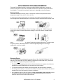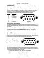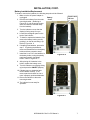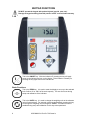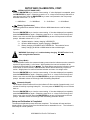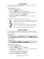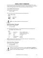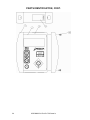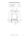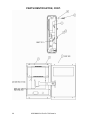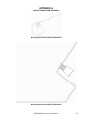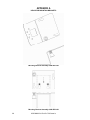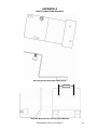
1
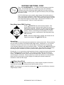
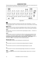
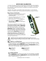
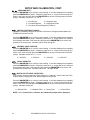
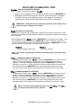
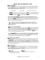
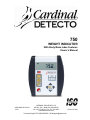
750 WEIGHT INDICATOR With Body Mass Index Features Owner’s Manual 8555-M483-O1 Rev B 10/13 CARDINAL SCALE MFG. CO. PO Box 151 Webb City, MO 64870 Ph: 417-673-4631 Fax: 417-673-5001 www.detectoscale.com Technical Support: Ph: 866-254-8261 8555-M483-O1 Rev B [email protected] 750 Owner’s Printed in USA 1 2 8555-M483-O1 Rev B 750 Owner’s TABLE OF CONTENTS INTRODUCTION . . . . . . . . . . . . . . . . . . . . . . . . . . . . . . . . . . . . . . . . . . . . . . . . . . SPECIFICATIONS . . . . . . . . . . . . . . . . . . . . . . . . . . . . . . . . . . . . . . . . . . . . . . . . . Standard Features . . . . . . . . . . . . . . . . . . . . . . . . . . . . . . . . . . . . . . . . . . . . . . . Optional Features . . . . . . . . . . . . . . . . . . . . . . . . . . . . . . . . . . . . . . . . . . . . . . . SITE PREPARATION REQUIREMENTS. . . . . . . . . . . . . . . . . . . . . . . . . . . . . . . . INSTALLATION . . . . . . . . . . . . . . . . . . . . . . . . . . . . . . . . . . . . . . . . . . . . . . . . . . Unpacking . . . . . . . . . . . . . . . . . . . . . . . . . . . . . . . . . . . . . . . . . . . . . . . . . . . . . Mounting . . . . . . . . . . . . . . . . . . . . . . . . . . . . . . . . . . . . . . . . . . . . . . . . . . . . . . Interconnections . . . . . . . . . . . . . . . . . . . . . . . . . . . . . . . . . . . . . . . . . . . . . . . . Load Cell Connection . . . . . . . . . . . . . . . . . . . . . . . . . . . . . . . . . . . . . . . . . . . . Serial Interface Specifications . . . . . . . . . . . . . . . . . . . . . . . . . . . . . . . . . . . . . . Serial I/O Port . . . . . . . . . . . . . . . . . . . . . . . . . . . . . . . . . . . . . . . . . . . . . . . . . . Optional AC Power Adapter . . . . . . . . . . . . . . . . . . . . . . . . . . . . . . . . . . . . . . . Batteries . . . . . . . . . . . . . . . . . . . . . . . . . . . . . . . . . . . . . . . . . . . . . . . . . . . . . . Battery Status . . . . . . . . . . . . . . . . . . . . . . . . . . . . . . . . . . . . . . . . . . . . . . . . . . Battery Charging . . . . . . . . . . . . . . . . . . . . . . . . . . . . . . . . . . . . . . . . . . . . . . . . Battery Installation/Replacement . . . . . . . . . . . . . . . . . . . . . . . . . . . . . . . . . . . . KEYPAD FUNCTIONS . . . . . . . . . . . . . . . . . . . . . . . . . . . . . . . . . . . . . . . . . . . . . Basic Functions . . . . . . . . . . . . . . . . . . . . . . . . . . . . . . . . . . . . . . . . . . . . . . . . . Body Mass Index Functions . . . . . . . . . . . . . . . . . . . . . . . . . . . . . . . . . . . . . . . ANNUNCIATORS . . . . . . . . . . . . . . . . . . . . . . . . . . . . . . . . . . . . . . . . . . . . . . . . . OPERATION . . . . . . . . . . . . . . . . . . . . . . . . . . . . . . . . . . . . . . . . . . . . . . . . . . . . . Basic Weighing Operation . . . . . . . . . . . . . . . . . . . . . . . . . . . . . . . . . . . . . . . . . Body Mass Index (BMI) Operation . . . . . . . . . . . . . . . . . . . . . . . . . . . . . . . . . . Weight Recall . . . . . . . . . . . . . . . . . . . . . . . . . . . . . . . . . . . . . . . . . . . . . . . . . . Serial ID Storage . . . . . . . . . . . . . . . . . . . . . . . . . . . . . . . . . . . . . . . . . . . . . . . . SETUP AND CALIBRATION . . . . . . . . . . . . . . . . . . . . . . . . . . . . . . . . . . . . . . . . SETUP REVIEW . . . . . . . . . . . . . . . . . . . . . . . . . . . . . . . . . . . . . . . . . . . . . . . . . . EVENT COUNTER . . . . . . . . . . . . . . . . . . . . . . . . . . . . . . . . . . . . . . . . . . . . . . . . WEIGHT ON DEMAND FORMATS . . . . . . . . . . . . . . . . . . . . . . . . . . . . . . . . . . . SERIAL PRINT COMMANDS . . . . . . . . . . . . . . . . . . . . . . . . . . . . . . . . . . . . . . . . ERROR AND STATUS DISPLAYS . . . . . . . . . . . . . . . . . . . . . . . . . . . . . . . . . . . . BEFORE YOU CALL SERVICE . . . . . . . . . . . . . . . . . . . . . . . . . . . . . . . . . . . . . . PARTS IDENTIFICATION . . . . . . . . . . . . . . . . . . . . . . . . . . . . . . . . . . . . . . . . . . . APPENDIX A – INDICATOR MOUNTING BRACKETS . . . . . . . . . . . . . . . . . . . . Serial Number ______________________ Date of Purchase ___________________ Purchased From ____________________ Page 1 Page 1 Page 1 Page 1 Page 3 Page 4 Page 4 Page 4 Page 4 Page 5 Page 5 Page 5 Page 6 Page 6 Page 6 Page 6 Page 7 Page 8 Page 8 Page 9 Page 10 Page 11 Page 11 Page 11 Page 12 Page 12 Page 13 Page 19 Page 19 Page 20 Page 21 Page 22 Page 22 Page 23 Page 27 PRECAUTIONS Before using this indicator, read this manual and pay special attention to all "NOTIFICATION" symbols: ___________________________________ ___________________________________ ___________________________________ IMPORTANT RETAIN THIS INFORMATION FOR FUTURE USE 8555-M483-O1 Rev B 750 Owner’s ELECTRICAL WARNING I1 FCC COMPLIANCE STATEMENT This equipment generates uses and can radiate radio frequency and if not installed and used in accordance with the instruction manual, may cause interference to radio communications. It has been tested and found to comply with the limits for a Class A computing device pursuant to Subpart J of Part 15 of FCC rules, which are designed to provide reasonable protection against such interference when operated in a commercial environment. Operation of this equipment in a residential area may cause interference in which case the user will be responsible to take whatever measures necessary to correct the interference. You may find the booklet “How to Identify and Resolve Radio TV Interference Problems” prepared by the Federal Communications Commission helpful. It is available from the U.S. Government Printing Office, Washington, D.C. 20402. Request stock No. 001-000-00315-4. PROPER DISPOSAL When this device reaches the end of its useful life, it must be properly disposed of. It must not be disposed of as unsorted municipal waste. Within the European Union, this device should be returned to the distributor from where it was purchased for proper disposal. This is in accordance with EU Directive 2002/96/EC. Within North America, the device should be disposed of in accordance with the local laws regarding the disposal of waste electrical and electronic equipment. It is everyone’s responsibility to help maintain the environment and to reduce the effects of hazardous substances contained in electrical and electronic equipment on human health. Please do your part by making certain that this device is properly disposed of. The symbol shown to the right indicates that this device must not be disposed of in unsorted municipal waste programs. COPYRIGHT All rights reserved. Reproduction or use, without expressed written permission, of editorial or pictorial content, in any manner, is prohibited. No patent liability is assumed with respect to the use of the information contained herein. DISCLAIMER While every precaution has been taken in the preparation of this manual, the Seller assumes no responsibility for errors or omissions. Neither is any liability assumed for damages resulting from use of the information contained herein. All instructions and diagrams have been checked for accuracy and ease of application; however, success and safety in working with tools depend to a great extent upon the individual accuracy, skill and caution. For this reason the Seller is not able to guarantee the result of any procedure contained herein. Nor can they assume responsibility for any damage to property or injury to persons occasioned from the procedures. Persons engaging the procedures do so entirely at their own risk. CAUTION CAUTION: RISK OF EXPLOSION IF BATTERY IS REPLACED BY AN INCORRECT TYPE. DISPOSE OF USED BATTERIES ACCORDING TO THE INSTRUCTIONS. ATTENTION: RISQUE D'EXPLOSION SI LA BATTERIES EST REMPLACE'E PAR UN TYPE INCORRECT. REJETEZ LES BATTERIES UTILISE'ES SELON LES INSTRUCTIONS. 2II 8555-M483-O1 Rev B 750 Owner’s INTRODUCTION Thank you for purchasing our Model 750 Weight Indicator. It has been manufactured with quality and reliability at our factory in Webb City, MO USA. This Indicator has been tested before leaving our factory to insure accuracy and dependability for years to come. This manual is provided to guide you through installation, operation and maintenance of your indicator. Please read it thoroughly before attempting to install or operate your 750 and keep it handy for future reference. SPECIFICATIONS Power Requirements . . . . . . . . 6 “AA” Alkaline, Ni-Cad or NiMH batteries (not included) OR an optional 100 to 240 VAC 50/60Hz 12 VDC 1A wall plugin UL/CSA listed AC power adapter (Cardinal part number 6800-1045). Operating Temperature . . . . . . 14 to 104 ºF (-10 to +40 ºC) Display . . . . . . . . . . . . . . . . . . . Six digit, seven segment, 0.7 inch high LCD Sensitivity . . . . . . . . . . . . . . . . . 0 to 2.4 mV/V Signal Input Range . . . . . . . . . 0 to 12mV max. Transducer Excitation . . . . . . . 5.0 VDC Resolution . . . . . . . . . . . . . . . . 2,500 divisions Capacities . . . . . . . . . . . . . . . . up to 10,000 divisions noncommercial Division Value . . . . . . . . . . . . . 1, 2, or 5 Sample Rate . . . . . . . . . . . . . . 1 to 16 samples per second Auto Zero Range . . . . . . . . . . . 0.5 or 1 through 9 divisions Weighing Units . . . . . . . . . . . . . Pounds, kilograms, pounds/kilograms and kilograms/pounds Keyboard . . . . . . . . . . . . . . . . . Membrane type with 5 keys and 4 directional arrows Enclosure Size . . . . . . . . . . . . . 6.125" W x 6.75" H x 1.75" D (16 cm x 17 cm x 4 cm) Construction . . . . . . . . . . . . . . . Painted Steel Standard Features: Metric Conversion Auto Shut-Off Feature Serial I/O (Input/Output) Selectable Sleep-Mode Selectable Filtering Optional Features: Optional 12VDC AC Power Adapter 8555-M483-O1 Rev B 750 Owner’s 1 This page intentionally left blank. 2 8555-M483-O1 Rev B 750 Owner’s SITE PREPARATION REQUIREMENTS The Model 750 Weight Indicator is a precision weight indicating instrument. As with any precision instrument, it requires an acceptable environment to operate at peak performance and reliability. This section is provided to assist you in obtaining such an environment. Environmental The Model 750 Weight Indicator meets or exceeds all certification requirements within a temperature range of 14 to 104 °F (-10 to +40 °C). In order to keep cooling requirements to a minimum, the indicator should be placed out of direct sunlight and to provide adequate air circulation, keep the area around the indicator clear. Do not place the indicator directly in front of a heating or cooling vent. Such a location will subject the indicator to sudden temperature changes, which may result in unstable weight readings. Insure that the indicator has good, clean AC power and is properly grounded. In areas subject to lightning strikes, additional protection to minimize lightning damage, such as surge suppressors, should be installed. Electrical Power The 750 indicator has been designed to operate from a 100 to 240 VAC 50/60Hz 12 VDC 1A wall plug-in UL/CSA listed AC power adapter (Cardinal part number 6800-1045). Note that a special order is not required for operation at 230 VAC. The socket-outlet supplying power to the indicator should be on a separate circuit from the distribution panel and dedicated to the exclusive use of the indicator. The socket-outlet shall be installed near the equipment and shall be easily accessible. The wiring should conform to national and local electrical codes and ordinances and should be approved by the local inspector to assure compliance. On installations requiring 230 VAC power, it is the responsibility of the customer to have a qualified electrician install the proper power adapter plug that conforms to national electrical codes and local codes and ordinances. 8555-M483-O1 Rev B 750 Owner’s 3 INSTALLATION Unpacking Carefully remove indicator from shipping carton and inspect it for any damage that may have taken place during shipment. Keep carton and packing material for return shipment if it should become necessary. The purchaser is responsible for filing all claims for any damages or loss incurred during transit. Should your indicator come already installed on a scale, the following installation information does not apply to you. Mounting To install the indicator on the bracket, place the screw heads on the back of the indicator into the large end of the slotted holes in the bracket. Pull down to secure the indicator. The spring plunger will lock the indicator to the bracket. See Figures No. 1, 2 and 3. Spring Plunger Serial I/O Connector Load Cell Connector AC Power Adapter Figure No. 1 Figure No. 2 Spring Plunger Release NOTE: The mounting bracket on your scale may be different than the one shown in Figures No. 2 and 3. Refer to Appendix A for other bracket types. Figure No. 3 Interconnections The load cell input and power connections are made at the bottom rear panel of the indicator. Refer to Figure No. 1 for the rear panel layout. 4 8555-M483-O1 Rev B 750 Owner’s INSTALLATION, CONT. Interconnections All input, output and power connections are made at the bottom rear panel of the indicator. Refer to Figure No. 1 for the rear panel layout. Load Cell Connection The load cell cable connects to the 750 via a 9-pin "D" connector on the rear panel of the indicator. Figure No. 4 shows the pin identification for the load cell connector. Make certain that the pins are correctly identified before soldering a wire to them. Use the connector retaining screws to hold the load cell cable connector securely to the rear panel. PIN NO. 1 2 3 4 5 6 7 8 9 FUNCTION +EXCITATION -SIGNAL no connection no connection SHIELD -EXCITATION +SIGNAL no connection no connection 5 4 3 9 2 8 1 7 6 Figure No. 4 Serial Interface Specifications The 750 Serial interface can be configured during the setup and calibration procedure or during the setup review operation. Using either method, it is possible to select the operation of the interface. The serial interface may be connected to a computer for transmission of weight and associated data to a PC-based EMR (electronic medical record) software program. The data can be transmitted on demand by pressing the Down Arrow/Print (/) key or on receipt of a command from the computer. Note that the serial interface can also be connected to a printer to record weight and associated data. Serial I/O Port The 750 RS-232 serial I/O port is a 9-pin "D" connector on the rear panel of the indicator. Figure No. 5 shows the Serial I/0 connector along with the identity of the pins used. Make certain that the pins are correctly identified before soldering a wire to them. Use the connector retaining screws to hold the serial cable connector securely to the rear panel. PIN NO. 2 3 5 FUNCTION DATA INPUT (RXD) DATA OUTPUT (TXD) SIGNAL GROUND (GND) 1 2 6 3 7 4 8 5 9 Figure No. 5 Note that pins 1, 4 and 6 through 9 are not used. The 750 RS-232 serial interface can be configured during the setup and calibration procedure or during the setup review operation. Using either method, it is possible to select the operation of the serial interface as well as select the baud rate. The baud rates supported are: 4800, 9600, 19.2K and 38.4K baud. The data format is fixed at 8 bits, No parity, and 1 stop bit. The indicator is shipped from the factory with the baud rate set to 9600 baud. 8555-M483-O1 Rev B 750 Owner’s 5 INSTALLATION, CONT. Optional AC Power Adapter To power the 750 using the optional 12 VDC wall plug-in AC power adapter, connect the plug from the adapter into the power jack on the back of the indicator and then plug the power adapter into the proper electrical outlet. Refer to Figure 1. On models requiring 230 VAC, it is the customer’s responsibility to obtain the correct power adapter plug. Batteries The 750 indicator can use 6 "AA" size Alkaline, Ni-Cad or NiMH batteries (not included). You must first obtain and install batteries before operations can begin. Batteries are contained in a battery holder inside the indicator. Access is via a removable panel on the back of the indicator. CAUTION! The 750 can be operated from Alkaline, Ni-Cad or NiMH batteries. All six (6) batteries must be of the same type. They must all be Alkaline, all Ni-Cad or all NiMH. DO NOT mix Alkaline and Ni-Cad or NiMH batteries. WARNING! The AC power adapter is also used to recharge the batteries, when the 750 is operated from Ni-Cad or NiMH batteries. DO NOT connect the AC power adapter to the 750 if using Alkaline batteries. Also, when using Alkaline batteries, make sure the niCAd setup option is disabled (set to 0). Refer to Setup and Calibration or Setup Review. Battery Status The 750 indicator will operate for up to 250 hours on new Alkaline batteries or for up to 100 hours on fully charged Ni-Cad or NiMH batteries depending on the condition of the batteries (from new to about 500 recharges). The battery bar graph on the display indicates the battery capacity in 4 steps: 4 segments - the full battery capacity is available, 3 segments - the battery is at 75% of capacity, 2 segments - the battery is at 50% of capacity, 1 segment: - the battery is at 25% capacity. When the battery voltage drops too low for accurate weighing, the indicator will show LoBAt and then shut off. You will be unable to turn the indicator back on until the Alkaline batteries have been replaced or if using Ni-Cad or NiMH batteries, the AC power adapter is connected to the display to operate it and recharge the batteries. Battery Charging To recharge the Ni-Cad or NiMH batteries, the AC power adapter must be connected to a power outlet and plugged into the indicator. It will take approximately 8 to 10 hours to fully recharge the batteries in the display. Charging the batteries for more than 10 hours will not damage them. NOTE: The indicator may be operated while the batteries are charging. 6 8555-M483-O1 Rev B 750 Owner’s INSTALLATION, CONT. Battery Installation/Replacement To install or remove the batteries, the following steps should be followed: 1. Make sure the AC power adapter is unplugged. Battery 2. Remove the indicator from the scale mounting bracket. (Referring to Figure No. 3, pull the spring plunger down and slide the indicator away from the bracket). Push in and lift here Cover 3. Turn the indicator over so that the display is facing away from you. 4. Locate the rectangular panel on the back of the indicator. 5. To install or replace the batteries, first remove the battery holder cover by pushing in on the tab and lifting it up. Refer to Figure No. 6. 6. If installing new batteries, proceed to step 7. If replacing the batteries, remove all 6 batteries from the battery holder and then proceed to step 7. 7. Install the 6 new “AA” size batteries in the battery holder, noting the polarity markings located in the battery holder. Refer to Figure No. 7. Figure No. 6 8. After placing all 6 batteries in the holder, replace the battery cover. 9. Turn the indicator over (display facing up) and press the ON/OFF (I/O) key. 10. If display turns on, batteries have been installed correctly. If not, remove panel and check for one or more improperly positioned batteries. 11. Return the indicator to the scale mounting bracket. + - + + - + 12. The indicator is now ready for operation. + - - + Figure No. 7 8555-M483-O1 Rev B 750 Owner’s 7 KEYPAD FUNCTIONS DO NOT operate the keypad with pointed objects (pencils, pens, etc). Damage to keypad resulting from this practice is NOT covered under warranty. This is the ON/OFF key. With the indicator off, pressing this key will apply power to the indicator and turn on the display. If the indicator is already on, pressing the key again will turn the indicator off. Basic Functions This is the ZERO key. It is used to reset the display to zero up to the selected limit of either 4% or 100% of the scale capacity. The zero limit is set during setup and calibration of the indicator. This is the UNITS key. It is used to change the weighing units to the alternate units of measurement. For example, with pounds displayed, pressing this key will change the weighting units to kilograms. NOTE: This feature must be enabled during setup and calibration for this key to be operational. 8 8555-M483-O1 Rev B 750 Owner’s KEYPAD FUNCTIONS, CONT. This is the LOCK/RELEASE key. It is used to lock and release (unlock) the display. If the HOLD feature was enabled during setup and calibration, pressing this key (after obtaining a stable weight) will cause the indicator to lock onto the weight. Pressing this key again will release (unlock) the display and return it to zero. If AUTO LOCK feature was enabled, weight display will lock after placing a load on the scale and obtaining a stable weight. Pressing this key will release (unlock) the display and return it to zero, or if another load is applied, lock onto new weight after obtaining a stable weight. Note that the lock feature is for non-commercial (NOT "Legal for Trade") applications. Body Mass Index (BMI) Functions The H / (BMI/ENTER) key serves several purposes. First, during setup parameters, pressing it will display the current setting of the parameter. Second, it is used to signal completion of the data entry and causes the indicator to process the data entered. Third, it is used during normal operation to enter the height (feet and inches or centimeters) for the Body Mass Index (BMI) calculation. NOTE: Unless the weight display is stable, the indicator will not respond to pressing the H / (BMI/ENTER) key. Arrow Keys The arrow keys are used during setup and calibration to select setup values. During operation, they are used to increase or decrease the BMI height values. Pressing the or keys will increment or decrement the value of the selected digit. Pressing the or will move the cursor (blinking character) to the next character position. Pressing the H / (BMI/ENTER) key will save the value entered and advance to the next prompt. Note, that when moving through the setup prompts, the default or previously selected value appears first on the display. Pressing the or keys during normal operation will enter a weight recall option allowing the last 10 weights recorded to be reviewed. The weight is recorded each time the weight is locked. The ZERO key can be used to clear the recorded values. Use the or keys to scroll through the 10 records. Press any other key to return the indicator to normal operation. Note that while reviewing the recorded weights, the display will alternate between the transaction number and the weight. / (Down Arrow/Print) During operation, the / (Down Arrow/Print) key is used to signal completion of the data entry, process the data entered and print the data if a printer is used. NOTE: The indicator will not respond to pressing the / (Down Arrow/Print) key unless the weight display is stable. 8555-M483-O1 Rev B 750 Owner’s 9 ANNUNCIATORS The annunciators are turned on to indicate that the display is in the mode corresponding to the annunciator label or that the status indicated by the label is active. Figure No. 9 The low battery annunciator is located in the upper left corner of the display. It is used to indicate the battery status. Refer to Power Connection section of this manual for more details. (STABLE) This annunciator is turned on when the weight display is stable. When off, it means that the change in successive weight samples is greater than the motion limits selected during setup. ZERO This annunciator is turned on to indicate that the weight displayed is within +/- 1/4 division of the center of zero. LOCK This annunciator is turned on to show that the indicator is locked onto the displayed weight. In operation, after obtaining a stable weight, pressing the LOCK/RELEASE key will cause the indicator to lock onto the weight and turn on the annunciator. Pressing the key again (or dropping below the Auto Lock reset value) will unlock the display and turn off the annunciator. NOTE: The lock feature must be enabled during setup. BMI (Body Mass Index) This annunciator is turned on when displaying the calculated body fat. kg This annunciator is turned on to indicate that the displayed weight is in kilograms. lb This annunciator is turned on to indicate that the displayed weight is in pounds. cm This annunciator is turned on when the displayed height measurement is in centimeters. FEET INCHES These annunciators are turned on when the displayed height measurement is in feet and inches. 10 8555-M483-O1 Rev B 750 Owner’s OPERATION Basic Weighing Operation To Weigh 1. Press ON/OFF key to turn on indicator. 2. Press ZERO key to zero weight display. The ZERO and lb or kg annunciator will turn on to show that scale is ready for use. 3. Place patient on scale and read weight display. 4. Remove patient from scale. Zero Weight Display 1. If the indicator is not showing zero weight on the display, press ZERO key. 2. Weight display will return to zero. ZERO, STABLE and lb or kg annunciators will turn on to show a stable, center-of-zero weight condition. Metric Conversion Press UNITS key to toggle between pounds and kilograms. Note that lb or kg annunciator will turn on to show which weighing unit is active. Zero Weight Display with Item on Scale 1. Place item (wheelchair, walker, etc…) on scale. 2. Display will show weight of item on scale. 3. Press ZERO key. 4. Weight display will return to zero. ZERO, STABLE and lb or kg annunciators will turn on. The item's weight has been "zeroed off". 5. Proceed with weighing operation. Body Mass Index (BMI) Operation To Weigh and Calculate BMI 1. Press ON/OFF key to turn on indicator. 2. Press ZERO key to zero weight display. The ZERO and lb or kg annunciator will turn on to show that scale is ready for use. 3. Place patient on scale and read weight display. 4. Press BMI/ENTER key. 5. If pounds is the active weighing unit, display will change to show 5 FEET, 6 INCHES with the 6 blinking. (The blinking character is the position to be changed). a. Press or keys until desired height in inches is displayed and then press or key to move the blinking character to FEET. b. Press or keys until desired height in feet is displayed. c. Proceed to Step 7. 6. If kilograms is the active weighing unit, display will change to show 170 cm.with the 0 of 170 blinking. (The blinking character is the position to be changed)... a. Press or keys until the desired number is displayed. b. Press or key to move to next character to change. c. Repeat steps A and B until the desired height in centimeters is displayed. d. Proceed to Step 7. 7. Press BMI/ENTER key. 8. Read BMI on display. 9. Remove patient from scale. 10. Press BMI/ENTER key to return to weighing operation. NOTE: The BMI/ENTER key can be used to toggle between the calculated BMI value and the weight until the scale goes below 10% of capacity (40 lbs). At that point, a new height input is required. 8555-M483-O1 Rev B 750 Owner’s 11 OPERATION, CONT. Weight Recall Pressing the or keys during normal operation will enter a weight recall option allowing the last 10 weights recorded to be reviewed. The weight is recorded each time the weight is locked. The ZERO key can be used to clear the recorded values. Use the or keys to scroll through the 10 records. Press any other key to return the indicator to normal operation. NOTE: While reviewing the recorded weights, the display will alternate between the transaction number and the weight. In addition, the 10 recorded weights can only be viewed. They can not be printed. Serial ID Storage The 750 has been equipped with Serial ID storage for 200 records. Each ID stores the ID index, Weight, Height, BMI and Unit of measure. When the BMI/ENTER key is pressed, the indicator will assign the current values to a new ID and store the ID in memory. Next, the indicator will print the ticket in the mode selected during setup and calibration. Once the first print is finished, the indicator will allow more tickets to be printed, however it will not store the values again until the weight goes below 1/10 of the scale capacity. This prevents ID overlap until the next person steps on the scale. NOTE: Serial ID storage can only be printed, not viewed through the display. 12 8555-M483-O1 Rev B 750 Owner’s SETUP AND CALIBRATION Your Model 750 indicator has been thoroughly tested and calibrated before being shipped to you. If you received the indicator with a scale, calibration is not necessary. If the indicator is being connected to a scale for the first time or recalibration is necessary for other reasons, proceed as indicated. Calibration of the indicator is accomplished entirely by the keypad. To enter setup and calibration, the calibration switch must be pushed in and held while turning on the indicator. Begin Setup and Calibration: 1. With power off, remove the 2 screws from the left end cap (as viewed from indicator front) and remove the end cap. 2. Locate the calibration switch on the circuit board and push it in. See Figure No. 10. Calibration Switch 3. With the switch held in, press the ON/OFF key. 4. When display shows SETUP, release the calibration switch. The indicator is now ready for setup and calibration. During setup and calibration it is necessary to enter values using the indicator's keypad. When a prompt is displayed on the indicator, press the BMI/ENTER key to view the current setting. To retain the current setting and proceed to the next prompt, press the BMI/ENTER key again. To change a setting, press the or keys (up or down arrow) to scroll through and select a new value. After a new value has been selected, press the BMI/ENTER key to save it and advance to the next prompt. Note that some setup prompts have values with 2 or more digits. The blinking character is the position to be changed and can be advanced to the next position by pressing the or (left or right arrow) key. Figure No. 10 DO NOT operate the keypad with pointed objects (pencils, pens, etc). Damage to keypad resulting from this practice is NOT covered under warranty. USA= (DOMESTIC or INTERNATIONAL) This is the prompt to select whether the indicator is used in the USA (domestic) or outside the USA (international). Press the BMI/ENTER key to view the current setting. If the value displayed is acceptable, press the BMI/ENTER key again. Otherwise, press the or keys to scroll through and select a new value and then press the BMI/ENTER key to save it and proceed to the next prompt. Allowable values are: 0 or 1. USA=1 (Domestic) No Zero Limit CAP +4% to OC USA=0 (International) +/- 4% Zero Limit CAP +9 grads to OC int= (INTERVAL SETTING) Press the BMI/ENTER key to view the current setting. If the value displayed is acceptable, press the BMI/ENTER key again. Otherwise, press the or keys to scroll through and select a new value and then press the BMI/ENTER key to save it and proceed to the next prompt. Allowable values are: 1, 2 or 5. 8555-M483-O1 Rev B 750 Owner’s 13 SETUP AND CALIBRATION, CONT. Unit= (WEIGHING UNIT) Press the BMI/ENTER key to view the current setting. If the value displayed is acceptable, press the BMI/ENTER key again. Otherwise, press the or keys to scroll through and select a new value and then press the BMI/ENTER key to save it and proceed to the next prompt. Allowable values are: 1, 2, 3 or 4. 1 = Pounds Only 2 = Kilograms Only 3 = Pounds/Kilograms 4 = Kilograms/Pounds 5 = Pounds & Ounces/Kilograms (if USA=1) UnS= (MOTION (UNSTABLE) RANGE) The Motion (Unstable) Range is the number of divisions of change permitted before the STABLE annunciator turns off. Press the BMI/ENTER key to view the current setting. If the value displayed is acceptable, press the BMI/ENTER key again. Otherwise, press the or keys and the or keys to scroll through and select a new value and then press the BMI/ENTER key to save it and proceed to the next prompt. Allowable values are 0 through 99. dPP= (DECIMAL POINT POSITION) Press the BMI/ENTER key to view the current setting. If the value displayed is acceptable, press the BMI/ENTER key again. Otherwise, press the or keys to scroll through and select a new value and then press the BMI/ENTER key to save it and proceed to the next prompt. Allowable values are: 0, 1, 2, or 3. 0 = XXXXXX 1= XXXXX.X 2 = XXXX.XX 3 = XXX.XXX CAP= (SCALE CAPACITY) Press the BMI/ENTER key to view the current setting. If the value displayed is acceptable, press the BMI/ENTER key again. Otherwise, press the or keys and the or keys to scroll through and select a new value and then press the BMI/ENTER key to save it and proceed to the next prompt. Allowable values are: 1 through 99,999. FLT= (DIGITAL FILTER LEVEL SELECTION) Your indicator will arrive with factory filter settings of 1 = Minimal. Please check with Tech Support before changing filter level, break range and sample rate. Press the BMI/ENTER key to view the current setting. If the value displayed is acceptable, press the BMI/ENTER key again. Otherwise, press the or keys to scroll through and select a new value and then press the BMI/ENTER key to save it and proceed to the next prompt. Allowable values are: 0 = Minimal Filter 1 = Moderate Filter 2 = Heavy Filter 3 = Custom Filter NOTE: If 3 = Custom Filter is selected, two additional prompts will be displayed. 14 8555-M483-O1 Rev B 750 Owner’s SETUP AND CALIBRATION, CONT. F= (FILTER LEVEL) Press the BMI/ENTER key to view the current setting. If the value displayed is acceptable, press the BMI/ENTER key again. Otherwise, press the or keys to scroll through and select a new value and then press the BMI/ENTER key to save it and proceed to the next prompt. Allowable values are 1 (least amount of filtering) to 99 (greatest amount of filtering). BR= (BREAK RANGE) Press the BMI/ENTER key to view the current setting. If the value displayed is acceptable, press the BMI/ENTER key again. Otherwise, press the or keys to scroll through and select a new value and then press the BMI/ENTER key to save it and proceed to the next prompt. Allowable values are 1 to 99 which correspond to the number of division changes to break out of filtering. SR= (SAMPLE RATE) Press the BMI/ENTER key to view the current setting. If the value displayed is acceptable, press the BMI/ENTER key again. Otherwise, press the or keys to scroll through and select a new value and then press the BMI/ENTER key to save it and proceed to the next prompt. Allowable values are a minimum of 1 sample per second to a maximum of 16 samples per second in one sample per second intervals. CAL= (CALIBRATION) With the display showing CAL=, press the BMI/ENTER key. The display will change to show the current setting 0 (0=NO). If the scale has been previously calibrated and you wish to skip calibration and proceed to the HOLD= (Hold Mode) prompt, press the BMI/ENTER key and the previous calibration will be retained. To begin calibration, press the key to select 1 (yes) and then press the BMI/ENTER key. After pressing the BMI/ENTER key, the display will change to LOAd=. LoAd= (LOAD CALIBRATION WEIGHT) With the display showing LoAd= perform the following steps: 1. Make certain the scale platform is empty and free of debris. 2. Place the desired amount of calibrated test weights on the scale platform. A minimum of 50% of scale's capacity is required. However 70% to 100% is recommended. 3. Press the BMI/ENTER key. 4. If the value displayed is acceptable, press the BMI/ENTER key again. Otherwise, determine the exact amount of test weight placed on the scale platform and then using the or keys and the or keys scroll through and select the test weight amount. 5. Verify that the numbers selected are the same as the amount of the test weight and then press the BMI/ENTER key. 6. Starting at the left and preceding right, a series of dashes will appear on the display. The dashes will stay on the display momentarily, then disappear, after which the display will proceed to the next prompt. 8555-M483-O1 Rev B 750 Owner’s 15 SETUP AND CALIBRATION, CONT. UnLoAd= (UNLOAD CALIBRATION WEIGHT) After a moment, the display will change to UnLoad. 1. Remove the test weights from the scale platform and then press the BMI/ENTER key. 2. Starting at the left and preceding right, a series of dashes will appear on the display. The dashes will stay on the display momentarily, then disappear, after which the calibration factor will be saved and the display will proceed to the next prompt. IMPORTANT: During the time the dashes are appearing on the display, insure that the loaded (or empty) scale is stable. SEtGC (SET GRAVITY CONSTANT) This indicator is equipped with an acceleration of gravity function which means that it can be calibrated in one location and then adjusted to match the acceleration of gravity at the location where it will used. With the display showing setGC press the BMI/ENTER key to view the current setting. If the value displayed is acceptable, press the BMI/ENTER key again. Otherwise, press the or keys to scroll through and select a new value and then press the BMI/ENTER key to save it and proceed to the next prompt. Allowable values are: 0 or 1. SEtGC=0 Gravity Constant is NOT used SEtGC=1 Set Gravity Constant NOTE: If you select 1 (Set Gravity Constant) the following additional prompts will be displayed: CALGC= (CALIBRATED GRAVITY CONSTANT) The display will change to show CALGC=. Press the BMI/ENTER key to show the current setting. This is the acceleration of gravity value of the location where the scale was calibrated. If the value displayed is acceptable, press the BMI/ENTER key to save it. Otherwise, press the or keys and the or keys to scroll through and select a new value and then press the BMI/ENTER key to save it and proceed to the next prompt. Consult the factory Tech Support for the Acceleration of Gravity value for your location. OPGC= (OPERATING GRAVITY CONSTANT) The display will change to show oPGC=. Press the BMI/ENTER key to show the current setting. This is the acceleration of gravity value for the location where the scale will be operated. If the value displayed is acceptable, press the BMI/ENTER key to save it. Otherwise, press the or keys and the or keys to scroll through and select a new value and then press the BMI/ENTER key to save it and proceed to the next prompt. Consult the factory Tech Support for the Acceleration of Gravity value for your location. NOTE: Once the Gravity Constant has been set, both CALGC= and oPGC= must be set to the same value to disable it. 16 8555-M483-O1 Rev B 750 Owner’s SETUP AND CALIBRATION, CONT. HoLd= (HOLD MODE) Press the BMI/ENTER key to view the current setting. If the value displayed is acceptable, press the BMI/ENTER key again. Otherwise, press the or keys to scroll through and select a new value and then press the BMI/ENTER key to save it and proceed to the next prompt. Allowable values are: 0, 1, or 2. 0 = NO (disable) 1 = YES (enable) 2 = AUTO (Automatic Hold) If HoLd=0 or1 (NO or YES) is selected, proceed to tra= (Zero Tracking Range) prompt. If HoLd=2 (AUTO) is selected, an additional prompt bAnd= (Auto Lock Reset Band) will be displayed. Proceed to bAnd= prompt to continue setup. With Hold feature enabled (HoLd=1), the indicator will lock the displayed weight on the display when LOCK/RELEASE key is pressed. Pressing the key again will unlock display. If automatic hold (HoLd=2) is selected, the indicator will automatically lock the weight on the display after obtaining a stable weight value that exceeds the Auto Lock Reset Band value. Refer to Auto Lock Reset Band setup below. NOTE: The HOLD mode of operation is only used in non-commercial applications and must be DISABLED (set to 0 = NO) for "Legal for Trade" applications. bAnd= (AUTO LOCK RESET BAND) If Auto Lock is selected, the display will change to show the bAnd= (Auto Lock Reset Band) prompt. This is the number of division changes needed to reset the auto lock. For the Auto Lock to function, the load on the scale must rise above the bAnd= value (and remain stable). To release Auto Lock, the load on the scale must fall below the bAnd= value. At that point, the next weighing operation can begin. Press the BMI/ENTER key to view the current setting. If the value displayed is acceptable, press the BMI/ENTER key again. Otherwise, press the or keys and the or keys to scroll through and select a new value and then press the BMI/ENTER key to save it and proceed to the next prompt. Allowable values are: 0 through 99. trA= (ZERO TRACKING RANGE) Zero tracking range is a value in scale divisions that will be automatically zeroed off. Press the BMI/ENTER key to view the current setting. If the value displayed is acceptable, press the BMI/ENTER key again. Otherwise, press the or keys and the or keys to scroll through and select a new value and then press the BMI/ENTER key to save it and proceed to the next prompt. Allowable values are 1 through 18 (1 to 9 divisions by 0.5 divisions). Select 0 (zero) to disable zero tracking. PUO= (Power Up Zero) Press the BMI/ENTER key to view the current setting. If the value displayed is acceptable, press the BMI/ENTER key again. Otherwise, press the or keys to scroll through and select a new value and then press the BMI/ENTER key to save it and proceed to the next prompt. Allowable values are: 0 or 1. PUO=1 (YES) Weight display will be reset to zero automatically on power up PUO=0 (NO) weight display will not be reset to zero 8555-M483-O1 Rev B 750 Owner’s 17 SETUP AND CALIBRATION, CONT. BAUD= (SERIAL OUTPUT BAUD RATE) Press the BMI/ENTER key to view the current setting. If value displayed is acceptable, press the BMI/ENTER key again. Otherwise, press the or keys to scroll through and select a new value and then press the BMI/ENTER key to save it and proceed to the next prompt. Allowable values are: 1, 2, 3 or 4. 1 = 4800 Baud 2 = 9600 Baud 3 = 19.2k Baud 4 = 38.4k Baud niCAd (Battery Type Selection) This setting determines whether Alkaline, NiCad or NiMH batteries are used for battery operation. Press the BMI/ENTER key to view the current setting. If the value displayed is acceptable, press the BMI/ENTER key again. Otherwise, press the or keys to scroll through and select a new value and then press the BMI/ENTER key to save it and proceed to the next prompt. Allowable values are: 0, 1, or 2. 0= 1= 2= Alkaline batteries - battery charging is DISABLED NiCad or NiMH batteries - battery charging is ENABLED Battery charging is ENABLED and FORCED ON. This selection forces battery charging for NiCad or NiMH batteries that are discharged. WARNING! Selecting 1 or 2, enables battery charging. DO NOT select 1 or 2, when using Alkaline batteries. SLeeP= (Sleep Mode) The Sleep Mode feature also conserves battery power when the indicator remains unused for a period of approximately 1 to 9 minutes. When enabled, the load cell excitation will be reduced and the display will show SLEEP. The Sleep feature requires the indicator to remain at the center of zero to activate, unlike Automatic Shutoff feature which only requires no motion. Weight placed on scale will activate indicator and return it to weight mode. Press the BMI/ENTER key to view the current setting. If the value displayed is acceptable, press the BMI/ENTER key again. Otherwise, press the or keys to scroll through and select a new value and then press the BMI/ENTER key to save it and proceed to the next prompt. Allowable values are 0 through 9 with 0 disabling Sleep Mode ASH= (Automatic Shutoff) The Automatic Shutoff feature will turn the indicator off after a period of approximately 1 to 9 minutes of inactivity to prolong battery life. You must press the ON/OFF key to turn indicator back on. Press the BMI/ENTER key to view the current setting. If the value displayed is acceptable, press the BMI/ENTER key again. Otherwise, press the or keys to scroll through and select a new value and then press the BMI/ENTER key to save it and proceed to the next prompt. Allowable values are 0 through 9 with 0 disabling Automatic Shutoff. Setup and Calibration Is Completed The setup and calibration process has been completed. The indicator will reset and then display weight. Remove power from the indicator and re-assemble for use. The indicator is now ready for normal operation. 18 8555-M483-O1 Rev B 750 Owner’s SETUP REVIEW The 750 indicator allows several operational parameters to be reviewed and changed as necessary without having to enter the setup mode. To Enter Setup Review: 1. If indicator is on, press ON/OFF key. 2. Display will show oFF and indicator will turn off. 3. Press and hold BMI/ENTER key and then press ON/OFF key. 4. Indicator will perform a lamp test (turn on all segments of display), display model number and software revision and then display tra= prompt. 5. With display showing tra=, release BMI/ENTER key. 6. Refer to instructions listed in Setup and Calibration section for information on how to change parameters. Parameters in Setup Review will be processed in the following sequence: tra Select the number of scale divisions automatically zeroed on power up PUO Enable or Disable automatic reset of weight display to zero on power up baud= Select baud rate for serial output niCAd Select to use Ni-Cad, NiMH or Alkaline batteries and type of charging SLeeP Disable or select number of minutes of inactivity at zero for sleep mode ASH Disable or select number of minutes for automatic shutoff timer EVENT COUNTER The Model 750 Weight Indicator has been designed with an Event Counter type of security seal. When selected, the 750 will display two 3-digit numbers representing the Calibration and Configuration counters. Calibration Counter The calibration counter is incremented when a value in the calibration part of setup is changed (USA, int, Unit, UnS, dPP, CAP, FLt, F, br, Sr, CAL, SetGC, CALGC, OPGC). The counter is only incremented 1 time even if more than one parameter is changed each time through setup. Configuration Counter The configuration counter is incremented when a value in the configuration part of setup is changed (Hold, bAnd, trA, PUO, BaUd, niCAd, SLEEP, ASH). The counter is only incremented 1 time even if more than one parameter is changed each time through setup. To Review the Event Counter: 1. If indicator is on, press ON/OFF key. 2. Display will show oFF and indicator will turn off. 3. Press and hold the UNITS key and then press ON/OFF key. 4. The display will then show CAL CH (Calibration Check) for two (2) seconds followed by two 3-digit numbers. The left number represents the setup Configuration counter. The right number represents the Calibration counter. 5. To return to the normal operation, press the UNITS key. 6. Otherwise press the ON/OFF key to turn off the indicator. 8555-M483-O1 Rev B 750 Owner’s 19 WEIGHT ON DEMAND FORMATS Weight On Demand If the indicator is connected to a computer for transmission of weight data to a PC-based EMR (electronic medical record) software program, it will transmit a single set of weight data each time the computer sends an weight request “ENQ” (hex 05). This is known as Weight-OnDemand. The host device (computer) sends: ENQ (hex 05) The 750 will respond: Weight, BMI, Height Where: Weight: BMI: Height: xxx.xuu G xx.x x' xx.x” NOTE: The “ENQ” command will only work when the Unit= parameter is set to 1 (Pounds Only), 2 (Kilograms Only), 3 (Pounds/Kilograms) or 4 (Kilograms/Pounds). 20 8555-M483-O1 Rev B 750 Owner’s SERIAL PRINT COMMANDS The Serial port on the 750 is a bi-directional port and can receive and transmit data. It can output to a printer as well as communicate to a computer. Using the serial port, it is possible to control the printing operation of the 750 by transmitting commands to the indicator. Journal Mode Print Command The host device (computer) sends: <LF> P <CR> The ticket will be printed (or data transmitted) in the following format: Weight, BMI, Height Where: Weight: BMI: Height: xxx.xuu G xx.x x' xx.x” NOTE: If ID or BMI are disabled, the field will be left out. Recall Data Queue Command The host device (computer) sends: <LF> XS <CR> The 750 will Recall the Data Queue. The data will be transmitted in the following format: ID, Weight, Units, Mode<cr><lf> Where: ID = Weight = Units = m= cr = lf = xxxxxxxxxxx xxxxxx.x uu Mode Carriage Return Line Feed Up to 11 digit ID number Six digits with decimal point None, lb, kg, oz, g, st G = Gross (hex 0D) (hex 0A) NOTE: Recalling the data queue does not delete the current data. The separate delete command must be sent to clear the queue. Delete Data Queue Command The host device (computer) sends: <LF> XD <CR> The 750 will Delete the Data Queue. Serial Print commands operate the same as pressing Down Arrow ()/PRINT key. They allow multiple printings, but will only store the values once until the weight goes below the 1/10 of scale capacity threshold. 8555-M483-O1 Rev B 750 Owner’s 21 ERROR AND STATUS DISPLAYS Display Meaning -Err- General error, invalid keypad entry was attempted. -ouF- Attempting to display a negative number greater than –99,999 or a positive number greater than 999,999 -trL- Indicates an attempt to zero a weight outside scale zero range. (See Four Percent Zero Tracking Range Limit). -UnS- Motion is present when indicator is attempting to perform one of the following operations: Power Up Zero or Zero Weight Display CALib Indicates calibration is necessary. AdErr ErrAL Consult your scale service representative. ErrAH OCAP OFF Scale weight exceeds scale capacity Displayed to indicate indicator is turning off. BEFORE YOU CALL FOR SERVICE PROBLEM Display does not turn on POSSIBLE SOLUTIONS AC Operation: Is AC power adapter fully inserted into wall receptacle? Check wall receptacle for proper AC power. Try another electrical appliance in same receptacle, does it work? Check circuit breaker. Has there been power failure? Battery operation: Check if batteries are installed and correctly. Are batteries discharged? If Alkaline, remove old batteries and replace with new ones. If NI-CAD or NiMH, connect the 12 VDC AC power adapter's connector into the jack on the back of the indicator and then plug the power adapter into the proper electrical outlet to operate the indicator and recharge the batteries. Incorrect weight displayed Insure that scale platform isn't touching an adjacent object. Have proper operation procedures been followed? Indicator will not display weight Refer to Error and Status Displays section. 22 8555-M483-O1 Rev B 750 Owner’s PARTS IDENTIFICATION Item Qty Part Number Description 1 1 8555-D264-08 KEYPAD 2 1 8555-D478-0A PCB ASS’Y 750 CONTROLLER (SMT) 3 1 8555-C473-08 REAR PANEL, 750DS 4 1 8555-C253-08 FRONT PANEL 5 2 8555-C213-08 END CAP 6 1 8555-B257-0A BATTERY HOLDER 7 2 8555-B254-08 MOUNTING SPACER 8 4 6680-0004 WASHER, #6 LOCK INT. TOOTH 9 2 6610-2000 JACK SOCKET 10 4 6021-6008 SCREW, #6 X .375 TH SHEET METAL (BLACK) 11 4 6021-2069 SCREW, #6X.50 TH SHEET METAL 12 2 6021-0687 SCREW, #6-32X.312 THMS W/THD-LOCK PATCH 13 1 593GR986 SERIAL TAG 14 2 6680-0052 WASHER, #4 LOCK HELICAL 15 1 8555-B263-08 LABEL: POWER 16 AR 6560-0021 LOCTITE #222 17 1 5930-B126-08 LABEL: ETL FOR 180/200/204/750/758C 1 6800-1045 OPTIONAL AC ADAPTER 100-240VAC/12VDC @ 1 AMP NOT SHOWN 8555-M483-O1 Rev B 750 Owner’s 23 PARTS IDENTIFICATION, CONT. 24 8555-M483-O1 Rev B 750 Owner’s PARTS IDENTIFICATION, CONT. 8555-M483-O1 Rev B 750 Owner’s 25 PARTS IDENTIFICATION, CONT. 26 8555-M483-O1 Rev B 750 Owner’s APPENDIX A INDICATOR MOUNTING BRACKETS Mounting Bracket Assembly 0033-B438-0A Mounting Bracket Assembly 0033-B439-0A 8555-M483-O1 Rev B 750 Owner’s 27 APPENDIX A INDICATOR MOUNTING BRACKETS Mounting Bracket Assembly 0044-B315-0A Mounting Bracket Assembly 0046-B516-0A 28 8555-M483-O1 Rev B 750 Owner’s APPENDIX A INDICATOR MOUNTING BRACKETS Mounting Bracket Assembly 0049-C039-0A 2.00 Inches Desk/Wall Mount Bracket Assembly 0033-B440-0A 8555-M483-O1 Rev B 750 Owner’s 29 STATEMENT OF LIMITED WARRANTY Detecto Scale warrants its equipment to be free from defects in material and workmanship as follows: Detecto warrants to the original purchaser only that it will repair or replace any part of equipment which is defective in material or workmanship for a period of one (1) year from date of shipment. Detecto shall be the sole judge of what constitutes a defect. During the first ninety (90) days Detecto may choose to supply all necessary replacement parts and service during normal weekday working hours at no charge to the buyer. After the first ninety (90) days Detecto will supply parts and service at the job site provided the owner agrees to pay the Dealer for all travel time, including mileage and test equipment, as well as any expenses incurred over the direct labor of the technician at the job site. This limited warranty honors only labor performed by Detecto authorized dealers. This warranty does not apply to peripheral equipment not manufactured by Detecto; this equipment will be covered by certain manufacturer’s warranty only. This warranty does not include replacement of expendable or consumable parts. This does not apply to any item which has deteriorated or damaged due to wear, accident, misuse, abuse, improper line voltage, overloading, theft, lightning, fire, water or acts of God, or due to extended storage or exposure while in purchaser’s possession. This warranty does not apply to maintenance service. Purchased parts will have a ninety (90) day repair or replacement warranty only. Detecto may require components be returned to the factory; they must be properly packed and shipping charges prepaid. A return authorization number must be obtained for all returns and marked on the outside of all returned packages. Detecto accepts no responsibility for loss or damage in transit. 30 8555-M483-O1 Rev B 750 Owner’s STATEMENT OF LIMITED WARRANTY Conditions Which Void Limited Warranty This warranty shall not apply to equipment which: A.) Has been tampered with, defaced, mishandled or have had repairs and modifications not authorized by Detecto. B.) Has had serial number altered, defaced, or removed. C.) Has not been grounded according to Detecto’s recommended procedure. Freight Carrier Damage Claims for equipment damaged in transit must be referred to the freight carrier in accordance with freight carrier regulations. This warranty sets forth the extent of our liability for breach of any warranty or deficiency in connection with the sale or use of the product. Detecto will not be liable for consequential damages of any nature, including but not limited to, loss of profit, delays or expenses, whether based on tort or contract. Detecto reserves the right to incorporate improvements in material and design without notice and is not obligated to incorporate improvements in equipment previously manufactured. The foregoing is in lieu of all other warranties, express or implied including any warranty that extends beyond the description of the product including any warranty of merchantability or fitness for a particular purpose. This warranty covers only those Detecto products installed in the forty-eight (48) contiguous continental United States. Ph. (800) 641-2008 E-mail: [email protected] 203 E. Daugherty Webb City, MO 64870 8555-M483-O1 Rev B 750 Owner’s 02/06 Printed in USA D268-WARRANTY-DET 31 32 8555-M483-O1 Rev B 750 Owner’s